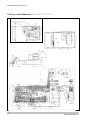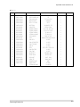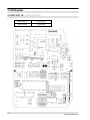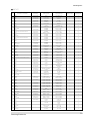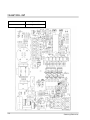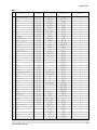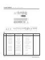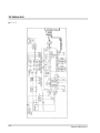
1
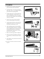
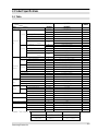
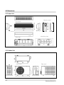
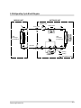
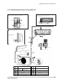
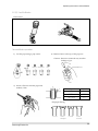
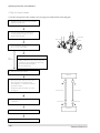
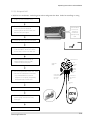
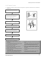
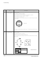
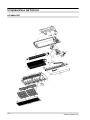
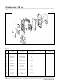
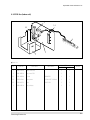
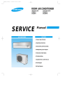
ROOM AIR CONDITIONER
INDOOR UNIT
AQV12F2VE
SERVICE
OUTDOOR UNIT
UQV12A0TE
Manual
AIR CONDITIONER
CONTENTS
1. Precautions
2. Product Specifications
3. Operating Instructions and
Installation
4. Disassembly and Reassembly
5. Troubleshooting
6. Exploded Views and Parts List
7. PCB Diagrams
8. Wiring Diagrams
1. Precautions
1. Warning: Prior to repair, disconnect the
power cord from the circuit breaker.
2. Use proper parts: Use only exact replacement parts. (Also, we recommend replacing
parts rather than repairing them.)
3. Use the proper tools: Use the proper tools
and test equipment, and know how to use
them. Using defective tools or test equipment may cause problems later-intermittent
contact, for example.
Fig. 1-1 Avoid Dangerous Contact
4. Power Cord: Prior to repair, check the
power cord and replace it if necessary.
5. Avoid using an extension cord, and avoid
tapping into a power cord. This practice
may result in malfunction or fire.
6. After completing repairs and reassembly,
check the insulation resistance. Procedure:
Prior to applying power, measure the resistance between the power cord and the
ground terminal. The resistance must be
greater than 30 megohms.
Fig. 1-2 No Tapping and No Extension Cords
7. Make sure that the grounds are adequate.
8. Make sure that the installation conditions
are satisfactory. Relocate the unit if necessary.
9. Keep children away from the unit while it is
being repaired.
10. Be sure to clean the unit and its surrounding area.
Fig. 1-3 No Kids Nearby!
Fig. 1-4 Clean the Unit
Samsung Electronics
1-1
2. Product Specifications
2-1 Table
Model (Indoor)
(Outdoor)
ø-V-Hz
Capacity
W
Btu/h
Cooling
Energy efficiency ratio
Btu/wh
Air flow
m2/min
Moisture removal
L/h
Noise level Indoor
Performan
dBA
Outdoor
ce
Capacity
W
Btu/h
Heating
Energy efficiency ratio
Btu/wh
Air flow
m3/min
Noise level Indoor
dBA
Outdoor
Available voltage range
V
Running amperes
A
Cooling
Power input
W
Power factor
%
Running amperes
A
Electrical
Heating
Power input
W
Rating
Power factor
%
Starting current
A
Fuse capacity
AXV
Power cord
AXV
Cable-connector
mm2 X C
Type
Compre
Model name
ssor
Safety devices
Indoor
Model name
Fan
Running capacitor
µF X VAC
Outdoor
Model name
motor
Running capacitor
µF X VAC
Refrigerant tube
Narrow tube : Liquid
mm X MT
Wide tube : Gas
mm X MT
Capillary tube
Cooling
mm
Heating
mm
Refrigerant to charge (R22)
gr
Dimension
Indoor unit : W x H x D
Outdoor unit : W x H x D
Weight
Indoor unit
Outdoor unit
AQV12F2VE
UQV12A0TE
1-220/240-50
3,500 (2,580~4,100)
12,000 (8,800~14,000)
9.4 (11.3~8.4)
8.4
1.9
36~40
51
3,800 (2580~4830)
13,000 (8800~16500)
9.8 (11.9~8.2)
8.8
34~38
52
187~264
5.6 (3.7~7.1), (MAX 12A↓)
1,280 (780~1,650)
95.0 (90.0~97.0)
5.7 (3.3~8.5), (MAX 12A↓)
1,330 (740~1,980)
98.0(94.0~97.0)
12 ↓
3.15X250 / 20X250
12 X 250
1.5 X 4
Single Rotary
48V135RV1E4
204CT
AMPFS-040WTVB
1.5 X 450
AMASS-020WTVB
1.5 X 450
OD6.35 X 5
OD12.7 X 5
ID1.7 X 800
ID1.7 X 600
1,000
815x298x193
762x532x280
9.2
44.0
Item
Power Source
Remark : Text condition
Samsung Electronics
Indoor room
Outdoor room
Cooling test
DB27˚C / WB19˚C
DB35˚C / WB24˚C
Heating test
DB20˚C /
DB 7˚C / WB 6˚C
-
Remark
2-1
2-2 Dimensions
2-2-1 Indoor Unit
(Remote control)
(Front view)
Air
in
Air out
(Rear view)
Installation plate
2-2-1 Outdoor Unit
(Front view)
2-2
(Rear view)
Samsung Electronics
2-3 Refrigerating Cycle Block Diagram
INDOOR UNIT
OUTDOOR UNIT
Capillary tube
T
2-way valve
Check valve
Liquid side
Capillary tube
Heat
exchanger
(Evaporator)
Heat
exchanger
(Condenser)
T
Gas side
3-way valve
4-way valve
Cooling
Compressor
Heating
Gas leak check point
Samsung Electronics
2-3
3. Operating Instructions and Installation
3-1 Operating Instructions
3-1-1 Name & Function of Key in remote controller
NO
FUNCTION OF KEY
NAMED OF KEY
On/Off Button. Use this button to start and stop air conditioner.
1
2
(UP)
Temp up button. If the button is pressed once,
the setting temperature is increased by 1°C
(DOWN)
Temp down button. If the button is pressed once,
the setting temperature is decreased by 1°C
Each time you press this button,
MODE is changed in the following order.
3
MODE
: Auto Mode
: Fan Only Mode
: Cool Mode
: Heat Mode
: Dry Mode
4
TURBO
Use this button to provide heavy duty cooling & Heating for 30 minutes.
5
OFF
Set up the reserve or cancel the timer on and timer off quickly
6
Use this button for sleep operation.
(The SLEEP mode can be selected at COOL and HEAT mode.)
7
Adjusts air flow vertically.
Each time you press this button,
FAN SPEED is changed in the following order.
8
9
10
11
12
13
C
O
V
E
R
T
I
M
E
R
ON TIMER
Set up the time that operation start.
OFF TIMER
Set up the time that operation stop.
SET
Use this button to reserve the timer on.
CANCEL
Use this button to reserve or cancel the timer on and timer off.
(UP)
If the
button is pressed once, the time increase by one minute
during the time set mode, and ten minutes during the timer set mode.
(DOWN)
If the
button is pressed once, the time decrease by one minute
during the time set mode, and ten minutes during the timer set mode.
14
15
TIME
Samsung Electronics
Without regard to ON/OFF condition in remote controller,
use this button to set current time.
Adjust the current time using
button.
(Data can be transmitted after setting up the time)
3-1
Operating Instructions and Installation
3-1-2 Name & Function of Key in remote controller
1. AUTO MODE : In this mode, operation
mode(COOL, HEAT) is selected automatically by the room temperature of initial
operation.
Room Temp
Operation Type
Tr≥ 21°C+∆T
Cool Operation (Set Temp:24°C+∆T)
21°C +∆T>Tr
Heat Operation (Set Temp : 22°C+∆T)
∆T= -2°, -1°C, 0°C+1°C+2°C
∆T is controlled by setting temperature
up(
)/down(
) key of remote
controller
2. COOL MODE : The unit operates according
to the difference between the setting and
room temperature. (18°C~30°C)
3. HEAT MODE : The unit operates according
to the difference between the setting and
room temperature.(16°C~30°C)
*Prevention against cold wind : For about
3~5 minutes after initial operation, thermo
control or “defrost”, the indoor fan will
either not operate or operate very slowly,
then switch to the selected fan speed. This
period is to allow the indoor unit's heatexchanger to prewarm before emitting
warm air.
*High temperature release function : The
outdoor unit for and compressor ON/OFF
control for safety operation, when the overheat is heat exchanger of indoor unit.
*Defrost : Deicing operation is controlled
by outdoor unit's heat exchanger temperature and outdoor temperature and accumulating time of compressor's operation.
De-ice end by sensing of the processing
time by de-ice Condition.
3-2
4. DRY MODE :
The unit operates in DRY mode.
*Protective function : Low temperature
release. (Prevention against freeze)
5. TURBO MODE : This mode is available in
AUTO, COOL, HEAT, DRY, FAN, SLEEP
Mode.
When this button is pressed at first, the air
conditioner is operated “powerful” state for
30 minutes regardless of the set temperature, room temperature.
When this button is pressed again, or when
the operating time is 30 minutes, turbo
operation mode is canceled and returned to
the previous mode.
*But, if you press the TURBO button in DRY
or FAN mode that is changed with AUTO
mode automatically.
6. SLEEP MODE : Sleep mode is available
only in COOL or HEAT mode.
The operation will stop after 6 hours.
*In COOL mode : The setting temperature
is automatically raised by 1°C each 1hour
When the temperature has been raised by
total of 2°C, that temperature is maintained.
*In HEAT mode : The setting temperature
is automatically droped by 1°C each 1hour.
When the temperature has been droped by
total of 2°C, that temperature is maintained.
7. FAN SPEED : Manual / Auto
Fan speed automatically varies depending
on both the difference between setting and
the room temperature.
Samsung Electronics
Operating Instructions and Installation
8. COMPULSORY OPERATION :
For operating the air conditioner without
the remote controller.
*AUTO : The operating is the same function that AUTO MODE in the remote controller.
9.
SWING : BLADE-H is rotated vertically by
the stepping motor.
*Swing Set / Auto : Press the
button
under the remote control is displayed on
LCD the
, and the blades move up and
down, about 43°. If the one more time press
the
button, blatles location is stop.
10. Quick OFF TIMER: OFF timer (quick timer)
allows reservation or cancel the timer on
and timer off quickly
When OFF timer button is pressed at operating state, LCD displays the polling state
sequentially.
The LCD also displays the time remaining.
11. 24-Hour ON/OFF Real Setting Timer. : The
air conditioner is turned ON at a specified
time using ON TIMER .
OFF TIMER : The air Conditioner is turned
OFF at a specified time using OFF TIMER .
*ON TIMER : Only timer LED lights on.
*OFF TIMER : Both timer and operation
LED lights on.
12. BUZZER SOUND : Whenever the ON/OFF
button is pressed or whenever change
occurs to the condition which is set up or
select, the compulsory operation mode,
buzzer is sounded "beep"
13. SELF Diagnosis
The indoor unit observes operation of the
air-conditioner, and displays the results of
self diagnosis on display pannel.
Samsung Electronics
Error mode
Opera- Defrost Reserva- Power
tion
tion
monitor
X
X
X
Fan Turbo
X
X
X
X
X
Operation off
X
X
X
X
X
Power reset
X
X
X
X
Trouble of indoor temperature
sensor (open/short)
X
X
X
X
Temperature sensor trouble of
the indoor heat exchanger
(open/short)
X
Stuck of the indoor fan motor
(trouble of rotation)
X
Trouble of outdoor unit temperature sensor
- Discharge temperature sensor
- OLP temperature sensor of
COMP top
- Defrost temperature sensor
- Outdoor temperature sensor
X
Communication trouble between
the indoor and outdoor units
(Misconnection or circuit trouble
of the indoor and outdoor units)
X
X
X
X
X
X
X
X
X
X
X
X
X
X
X
X
X
X
X
Abnormal increase of the operation current
X
X
Occurring of the inverter circuit
instantaneous over current.
X
Abnormal increase of the COMP.
Top and discharge gas temperature.
LAMP
ON
Refrigerant Refill operation (test
operation)
(Lamp status)
: Lamp flickering
X: Lamp off
14. AUTO RESTART : The air conditioner starts
immediately without control of remote
controller when plugged.
It’s the case that the Auto-restart fanction
works.
* Auto restart function is the convenient
function where the operation state is memorized in the Memory IC during the blackout and the operation restarts when the
power comes back.
3-3
3-2 Installation
(Fix the unit firmly if it is mounted in a
high place.)
3-2-1 Selecting Area for Installation
Select an area for installation that is suitable
to the customer's needs.
3-2-1(a) Indoor Unit
1. Make sure that you install the indoor unit in
an area providing good ventilation. It must
not be blocked by an obstacle affecting the
airflow near the air inlet and the air outlet.
2. Make sure that you install the indoor unit in
an area allowing good air handling and
endurance of vibration of the indoor unit.
3. Make sure that you install the indoor unit in
an area where there is no source of heat or
vapor nearby.
4. Make sure that you install the indoor unit in
an area from which hot or cool air is spread
evenly in a room.
3. Make sure that you install the outdoor unit
in area providing good ventilation and
which is not dusty. It must not be blocked
by any obstacle affecting the airflow near
the air inlet and the air outlet.
4. Make sure that you install the outdoor unit
in area free from animals or plants.
5. Make sure that you install the outdoor unit
in area not blocking the traffic.
6. Make sure that you install the outdoor unit
in area easy to drain condensed water from
the indoor unit.
7. Make sure that you install the outdoor unit
in area which provides easy connection
within the maximum allowable length of a
coolant pipe(10 meters).
Note
1. Add 10 grams of refrigerant (R-22) for
every 1 meter if the pipe length exceeds
the standard pipe length of 5 meters.
2. Maintain a height between the indoor and
outdoor units of less than 3 meters.
5. Make sure that you install the indoor unit in
an area away from TVs, audio units, cordless phones, fluorescent lighting fixtures
and other electrical appliances (at least 1
meter).
6. Make sure that you install the indoor unit in
an area which provides easy pipe connection with the outdoor unit, and easy
drainage for condensed water.
8. Make sure that you install the outdoor unit
in an area which is large enough to accommodate the measurements
shown in figure on the next page.
7. Make sure that you install the indoor unit in
an area which is large enough to accomodate the measurements shown in figure on
the next page.
3-2-1(c) Remote Control Unit
3-2-1(b) Outdoor Unit
1. Make sure that you install the outdoor unit
in area not exposed to the rain or direct sun
light.
(Install a separate sunblind if exposed to
direct sun light.)
2. Make sure that you install the outdoor unit
in area allowing good air moment, not
amplifying noise or vibration, especially to
avoid disturbing neighbours.
1.
Make sure that you install the remote control unit in an area free from obstacles such
as curtains etc, which may block signals
from the remote control unit.
2. Make sure that you install the remote control unit in an area not exposed to
direct sunlight, and where there is no source
of heat.
3. Make sure that you install the remote control unit in an area away from TVs, audio
units, cordless phones, fluorescent lighting
fixtures and other electrical appliances (at
least 1 meter).
Caution :
It is harmful to the air conditioner if it is used in the following environments: greasy areas (including areas near machines),
salty areas such as coast areas, areas where sulfuric gas is present such as hot spring areas. Contact your dealer for advice.
3-4
Samsung Electronics
Operating Instructions and Installation
3-2-2 Installation diagram of indoor unit and outdoor unit
A Indoor unit gas leak test check point
Piping may be laid to the rear, left,
right or down .
3
Indoor unit
Left
Right
2
Rear
Piping
Down
Rear
Tape vinyl
1
B Drain hose installation
100mm or more
160mm
or more
Cut the piping hole
sloped slightly
7 8 9
5
6
Remote control
Remote control holder
4
10
1
2
3
4
5
Samsung Electronics
9K BTU
12K BTU
Piping (Liquid) 1/4"
6
Clamper tube
Piping(Gas)3/8”
Piping(Gas)1/2”
7
Installation plate
8
Pipe-connection
Screw
Drain hose
Installation tube
Vinyl tape
Putty
9
10
3-5
Operating Instructions and Installation
3-2-2(a) Fixing the Installation Plate
1. Determine the position of the pipe and drain hose hole
using the right figure and drill the hole with an inner
diameter of 65mm so that it slants slightly downwards.
Installation plate
2. If you are fixing the indoor unit to a… Then follow Steps…
Pipe hole
(ø65mm)
Wall
3.
Window frame
4 to 6.
3. Fix the installation plate to the wall in a manner appropriate to the weight of the indoor unit.
(Unit : mm)
If you are mounting the plate on a concrete wall with
anchor bolts, the anchor bolts must not project by more
than 20mm.
280
(Unit : mm)
340
4. Determine the positions of the wooden uprights to be
attached to the window frame.
5. Attach the wooden uprights to the window frame in a
manner appropriate to the weight of the indoor unit.
6. Using tapped screws, attach the installation plate to the
wooden uprights, as illustrated in the last figure opposite.
3-2-2(b) Purging the Unit
On delivery, the indoor unit is loaded with an inert gas.
All this gas must therefore be purged before connecting the
assembly piping. To purge the inert gas, proceed as fol lows.
Unscrew the caps at the end of each pipe.
Result : All inert gas escapes from the indoor unit.
•
3-6
To prevent dirt or foreign objects from getting into
the pipes during installation, do NOT remove the
caps completely until you are ready to connect the
piping.
Samsung Electronics
Operating Instructions and Installation
3-2-2(c) Connecting the Assembly Cable.
The outdoor unit is powered from the indoor unit via the assembly
cable. If the outdoor unit is more than five metres away from the
indoor unit, the cable must first be extended to a maximum of ten
metres.
1. Extend the assembly cable if necessary.
Indoor unit
2. Open the front grille by pulling on the tabs on the lower right and
left sides of the indoor unit.
3. Remove the screw securing the connector cover.
Earth
terminal
4. Pass the assembly cable through the rear of the indoor unit and
connect the assembly cable to terminals C, N, L, E.
• Each wire is labelled with the corresponding terminal number.
Earth
terminal
Outdoor unit
L : Brown
N : Sky blue
C : Black
E : Yellow/ Green
5. Firmly fix the ass’y cable with clamp wire holder.
6. Pass the other end of the cable through the 65mm hole in the wall.
7. Replace the connector cover, carefully tightening the screw.
8. Close the front grille.
3-2-2(d) Installing and Connecting the Indoor Unit Drain Hose
Care must be taken when installing the drain hose for the indoor unit to ensure that any condensa tion water is correctly drained outside.l When passing the drain hose through the 65mm hole drilled
in the wall, check that none of the following situations occur.
The hose must
NOT slope upw
ards.
The end of the drain
hose must NOT be
placed in water.
Do NOT bend the
hose in different
directions.
Keep a clearance of at
least 5cm between the
end of the hose and the
ground.
Do NOT place the end
of the drain hose in a
hollow.
To install the drain hose, proceed as follows.
1. If necessary, connect the 2-metre extension to the drain hose.
2. If you are using the extension, insulate the inside part of the extension drain hose with a shield.
3. Pass the drain hose under the refrigerant piping, taking care to keep the drain hose tight.
4. Pass the drain hose through the hole in the wall, making sure that it is sloping downwards, as
shown in the illustrations above.
Shield
Drain hose
Samsung Electronics
Extension drain hose
3-7
Operating Instructions and
3-2-2(e) Outdoor unit installation
Wiring connection
1.
2.
3.
4.
5.
Remove the Handle-Cabi RH.
Firmly connect the cable connector in the terminal block.
Fasten the terminal to the hole marked
Firmly fix the ass'y cable with clamp wire holder.
Assemble the Handle-Cabi RH.
Installing and Connecting the Outdoor Unit Drain Hose
Drain hole
3-8
When using the air conditioner in the heating mode, ice may accumu late. During de-icing, the condensed water must be drained off safely.
Consequently, you must install a drain hose on the outdoor unit, fol lowing the instructions below.
1
Insert the drain plug into the drain hole on the underside of the
outdoor unit.
2
Connect the drain hose to the drain plug.
3
Ensure that the drained water runs off correctly and safely.
Samsung Electronics
Operating Instructions and Installation
3-2-2(f) Flare Modification
• Tools used
Flare modification procedure
1) Cut the pipe using a pipe cutter.
2) Remove burrs at the tip of the pipe cut.
Caution : Burrs not removed may result in
leakage of gas.
Pipe
Oblique Raughness
3) Insert a flare nut into the pipe and
modifty flare.
Reamer
Burr
D
Outer diameter
ø6.35mm
ø9.52mm
ø12.7mm
A
A(mm)
1.3
1.8
2.0
* Unproper flaring
Inclined
Samsung Electronics
Surface
damaged
Cracked
Uneven
thickness
3-9
Operating Instructions and Installation
3-2-2(g) Air-Purge Procedure
• Use the refrigerant of the outdoor unit to purge air inside indoor unit and pipe.
1. Remove the caps from the 2-way valve(B)
and the 3-way valve(A).
2. Turn the 2-way valve cock approx. 45°
counterclockwise to open it. Close it
about 10 seconds later.
Valve stem
Valve stem
Stopper
3. Check refrigerant leakage of each joint parts
(A, B, C & D in right figure)
not
leaking
Leaking
If leaking, tighten the flare nut one more time.
If continues to leak, although the pipe fixing
area has been tightened again,
repair the leaking area.
4. Open the 2-way valve again.
Indoor Unit
5. Open the service valve cap of the 3-way
valve and press the needle valve to
discharge gas for 3 seconds and leave it
for about 1 minute.
Repeat the above procedure for 3 times
to purge air.
6. Open the 2-way valve and 3-way valve
completely
Liquid pipe side
Gas pipe side
2-way valve
3-way valve
Outdoor Unit
7. Close the cap of each valve.
8. Check each valve for leakage.
3-10
Samsung Electronics
Operating Instructions and Installation
3-2-2(h) Refrigerant Refill
• Refill an air-conditioner with refrigerant when refrigerant has been leaked at installing or using
1. Purge air(for new installation only).
2. Turn the 3-way valve clockwise to close,
connect the pressure gauge(low
pressure side) to the service valve, and
open the 3-way valve again.
Press this ON/OFF
Switch for 5sec.
And then the
Aircondationer
operating on rating
speed.
3. Connect the tank to refill with Refrigerant
ON/OFF
4. Set the unit to Low pressure checking mode.
* Press the ON/OFF switch for 5 second.
*All the lamp is blink on the indoor unit.
5. Check the pressure indicated by the
pressure gauge(low pressure side).
* Refer to Low pressure graph.
Suspension hook
High
pressure
gauge
Compound
gauge
Hand
wheel
6. Open the refrigerant tank and fill with refrigerant until the rated pressure is reached.
* It is recommended not to pour the
refrigerant in too quickly, but gradually
while operating a pressure valve.
Finger tight
fittings
For mounting
other and of
hose when
not in use
Connected to
high pressure
side
Charging
line
7. Stop operation of the air conditioner.
8. Close the 3-way valve, disconnect the
pressure gauge, and open the 3-way
valve again.
9. Close the cap of each valve.
Samsung Electronics
3-11
Operating Instructions and Installation
6.5
32.4
6
30.6
5.5
28.8
27.0
5
24.0
4.5
21.5
4
3.5
20
25
30
35
40
45
Outdoor inlet air DB temp.(˚C)
3-2-2(i) Refrigerant Adjustment
Class
Connection
Pipe Length
5m Max.
At installation
At service
Air-Purge
Method
Refrigerant
Adjustment
Air-Purge
Method
Refer to the
detailed Air-Purge
Procedure
Unnecessary
Add 10g of refrigerant
(R-22) for every 1m.
5~10m
Purge air using a
vaccum pump
or an additional
refrigerant cylinder.
Refrigerant
Quantity
refer to
specification sheet
Add 10g of refrigerant
(R-22) for every 1m.
3-2-2(j) Flare unt fixing torque
Outter diameter
3-12
Torque (kg-cm)
Fixing Torque
Final Torque
ø 6.35 (9000Btu, 12000Btu)
(Liquid Side)
160
200
ø 9.52 (9000Btu)
(Gas Side)
300
350
ø 12.7 (12000Btu)
(Gas Side)
500
550
Samsung Electronics
Operating Instructions and Installation
3-2-2(k) "Pump down" Procedure
•
Pump down' shall be carried out when an evaporator is replaced or when the unit is relocated in
another area.
1. Remove the caps from the 2-way valve
and the 3-way valve.
2. Turn the 3-way valve clockwise to close
and connect a pressure gauge(low
pressure side) to the service valve, and
open the 3-way valve again.
(liquid)
(gas)
3. Set the unit to cool operation mode.
(Check if the compressor is operating.)
Valve stem
4. Turn the 2-way valve clockwise to close.
Stem cap
3-Way Valve
2-Way Valve
5. When the pressure gauge indicates "0"
turn the 3-way valve clockwise to close.
6. Stop operation of the air conditioner.
7. Close the cap of each valve.
Relocation of the air conditioner
• Refer to this procedure when the unit is
relocated.
1. Carry out the pump down procedure (r efer
to the details of 'pump down').
2. Remove the power cord.
3. Disconnect the assembly cable from the
indoor and outdoor units.
4. Remove the flare nut connecting the indoor
unit and the pipe.
At this time, cover the pipe of the indoor
unit and the other pipe using a cap or vinyl
plug to avoid foreign material entering.
Samsung Electronics
5. Disconnect the pipe connected to the outdoor
unit.
At this time, cover the valve of the outdoor
unit and the other pipe using a cap or vinyl
plug to avoid foreign material entering.
6. Make sure you do not bend the connection
pipes in the middle and store together with
the cables.
7. Move the indoor and outdoor units to a new
locatioon.
8. Remove the mounting plate for the indoor
unit and move it to a new location.
3-13
4. Disassembly and Reassembly
Stop operation of the air conditioner and remove the power cord before repairing the unit.
4-1 Indoor Unit
No
Parts
1
Front Grille
Procedure
Remark
1) Stop the air conditioner operation and block
the main power.
2) Separate tape of front panel upper.
3) Contract the second finger to the left, and
right handle and pull to open the inlet grille.
4) Take the left and right filter out.
* Take the Deadorizing and Electrostatic filter out.
(ONLY “1” and “5” Series models)
5) Loosen one of the right fixing screw and
separate the terminal cover.
6) Loosen three fixing screws of front grille.
7) Pull the upper left and right of discharge
softly for the outside cover to be pulled out.
8) Pull softly the lower part of discharge and
push it up.
Caution;
Assemble the front panel and fix the
hooks of left and right.
Samsung Electronics
4-1
Disassembly and Reassembly
No
Parts
2
Ass’y Tray Drain.
3
Electrical Parts
(Main PCB)
Procedure
Remark
1) Do “1”, above.
Separate the drain hose from the extension
drain hose.
2) Take the display PCB out.
(Center of indoor unit)
3) Loosen three fixing screws of left and right
4)Pull tray drain out from the back body.
1) Do “1”, “2”, above
2) Take all the connector of PCB upper side out.
(Inclusion Power cord)
3) Separate the outdoor unit connection wire
from the terminal block.
4) If pulling the Main PCB up. it will be taken
out.
(Separate the TRANS hook. it before).
4
Heat Exchanger
1) Do “1” and “2”, “3”, above
2) Loosen two fixing earth screws of right side.
3) Separate the connection pipe.
4) Separate the bush body at the upper side and
holder at the rearside.
5) Loosen the two fixing screws of left side.
6) Lifting the heat exchanger up a little to push
the up side for separation from the indoor
unit.
4-2
Samsung Electronics
Disassembly and Reassembly
No
Parts
5
Fan Motor and
Cross Fan
Procedure
Remark
1) Do “1” “2” ”3” “4”, above.
2) Loosen the fixing three screws and separate
the motor holder.
3) Loosen the fixing screw of fan motor.
(By use of M3 wrench)
4) Separate the fan motor from the fan.
5)Separate the fan from the left holder bearing.
Samsung Electronics
4-3
4-2 Outdoor Unit
Take care of the electrical shock by contact on the charging parts before the discharge
after power off. (If takes approximately 2minutes to discharge.)
No
Parts
1
Common Work &
Ass’y-control Out
Procedure
Remark
1) Loosen the fixing screw and separate the
Handle-Cabi RH.
2) Separate the Cable-Connector Wire from the
Terminal-Block.
3) Loosen six fixing screws and separate the
Cabi-Upper.
4) Loosen four fixing screws from the
Ass’y-Control Out.
5) Separate the Terminal-Housing from the
Ass’y-Control Out.
6) Separate the Ass’y-Control Out from the
outdoor unit.
7) Loosen five fixing screws and separate the
Cabi-Side.
4-4
Samsung Electronics
Disassembly and Reassembly
No
Parts
2
Fan-Motor
Procedure
Remark
1) Loosen fixing screw of the Guard-Fan.
2) Turn the Guard-Fan to separate from the
Cabi-Front.
4) Remove the nut flange (Turn to the right to
remove, as it is a left hand screw)
5) Separate the fan.
6) Loosen four fixing screws to separate the
motor.
3
Heat Exchanger
Samsung Electronics
1) Do “1”, above.
2) Loosen four fixing screws of Ass’y-Frame and
Partition.
3) Disassemble the inlet and outlet pipe by
welding.
4) Separate the heat exchanger.
4-5
Disassembly and Reassembly
No
Parts
Procedure
4
Compressor
1) Do “1”, above.
2) Open the terminal cover of compressor and
unscrew the connection terminal.
3) Disassemble the inlet and outlet pipe of compressor by welding.
4) Disassemble the inlet and outlet pipe of condenser by welding
Remark
5) Loosen the three bolts of the lower part.
6) separate the compressor.
4-6
Samsung Electronics
5. Troubleshooting
Since the inverter air conditioner is equipped with Electrical control circuits at both Indoor &
outdoor unit, the trouble shooting shall be performed according to the error mode.
Inside the controller of the outdoor unit (inverter), the large capacity of electrolytic condenser so
that it takes the time to discharge after the power off since the electrical charge remains
(the charging voltage DC 340V).
Take care of the electrical shock by contact on the charging part before the discharge after the
power off. (It takes approximately 2 minutes to discharge).
5-1 Basic items for trouble shooting
1) Is the power source proper?
The power source shall be in the range of the rated voltage ±10%. If it is out of this range, it may
cause the abnormal operation.
2) Is the connection made between the indoor and outdoor unit?
The connection between indoor and outdoor unit shall be performed with 4 wire. (connection
cable of indoor and outdoor unit + ground wire).
3) The phenomena as follows are not out of order.
NO
Phenomena
1 The operation is not done.
Cause and reason
Is the power off or the power unplugged?
Does it stop because it is the completion time?
• Unplug and plug again the power source for 2 minutes.
•
•
2 The wind comes out but the
heating/cooling is not
performed.
Is the filter clogged with dust or dirty?
Is there any direct light on the outdoor unit or any obstacle against it?
• Is the selected temperature too high? Lower the selected temperature lower than the current one (during cooling).
• Is the selected temperature too low? Raise the desired temperature than the current one?
• Is the “Fan only Mode” operation?
3 The remote controller does
not operate.
•
4 The wind volume is not
adjusted.
•
5 The reservation does not
operate.
6 The temperature is not set.
7 The operation lamp continues
to be flickering.
•
•
Is the battery run out?
Is the battery inserted in the wrong way(+, -)?
• Is the detection part of the indoor unit blocked?
• Does it interfered with the radio of neon sign?
•
Is the operation selected among one of Auto / Dry / Turbo / Sleeping?
The temperature setting is not required since the wind volume set automatically.
• Check again at the state of Cooling / Fan only / Heating.
•
•
•
Is the current time input? The reservation can be made only when the current time is input.
Is it on the stop condition? The reservation can not be made at the stop state. Press the
Operation / Stop button to make the reservation.
Is the operation selected among the Dry / Turbo / Sleeping / Fan only Mode.
Since the temperature is automatically set, the temperature setting is not required.
• Check again at the cooling/heating state.
• The standard temperature ±2˚C during the automatic operation.
•
•
•
Push the Operation / Stop button.
Unplug and plug the power source.
8 The immediate operation starts • It is the case that the auto restart function works.
without control of remote
# Auto restart function is the convenient function where the operation state is memorized in
controller when plugged
the Memory IC during the blackout and the operation restarts when the power comes back.
Samsung Electronics
5-1
5-2 The first determination method of troubled part
5-2-1 Error mode display of indoor unit
Operation
Defrost
Reservation
X
X
X
X
X
X
X
Error mode
Fan
Turbo
X
X
X
Operation off
X
X
X
Power reset
X
X
X
X
Trouble of indoor temperature sensor (open/short)
X
X
X
X
Temperature sensor trouble of the indoor heat exchanger
(open/short)
X
Stuck of the indoor fan motor (trouble of rotation)
X
X
Trouble of outdoor unit temperature sensor
- Discharge temperature sensor
- OLP temperature sensor of COMP top
- Defrost temperature sensor
- Outdoor temperature sensor
X
X
Communication trouble between the indoor and outdoor units
(Misconnection or circuit trouble of the indoor and outdoor
units)
X
X
X
X
X
X
X
X
X
X
X
X
X
X
Power monitor
X
X
X
Abnormal increase of the operation current
X
X
Occurring of the inverter circuit instantaneous over current.
X
LAMP
ON
Abnormal increase of the COMP. Top and discharge gas temperature.
Refrigerant Refill operation (test operation)
(Lamp status)
: Lamp flickering
5-2
X: Lamp off
Samsung Electronics
Troubleshooting
5-2-2 Error mode display of outdoor unit board
ERROR MODE
RED
GREEN
X
X
YELLOW
X
Operation off
X
Indoor-outdoor unit normal communication and operation
X
X
Abnormal communication between the indoor and outdoor unit
(miconnection or trouble of circuit between the indoor and outdor
unit)
X
X
X
Trouble of the control power of the outdoor(+12V)
X
X
Instantaneous over current of inverter circuit
X
Abnormal increase of the discharge temperature
Abnormal increase of operation current
X
Abnormal increase of comp top temperature.
X
Trouble of outdoor temperature sensor (open/short)
Trouble of the OLP temperature sensor (open/short)
Trouble of outdoor Heat exchanger temperature sensor (defrost temperature sensor) (open/short)
(LAMP
)
: LAMP ON
: LAMP FLICKERING
X : LAMP OFF
Samsung Electronics
5-3
5-3 Sequence of trouble shooting for inverter aircon
OPERTION START
. The indoor unit does not work
even though the power is plugged.
. There is no sound “ting”
. The lamp is not on the display.
Check the indoor unit control board. (A)
The indoor unit does not work when
operated by the remocon.
Checking the Remocon. (B)
Check the control board and the display
board of indoor unit.(C)
The lamp of the indoor display lamp is
flickering and the indoor unit stops several minutes after the indoor unit starts.
Check the error mode by confirming the
lamp flickering of indoor unit display.(D~N)
Reservation lamp( ) flickering
-> Check of the indoor temperature sensor (D)
Operation( ), Reservation( ) lamp flickering -> Check of the indoor heat exchanger (E)
Fan( ) lamp flickering
-> Check of indoor unit fan motor (F)
Reservation(
Operation(
Turbo lamp(
), Fan(
), Fan (
) lamp flickering
) lamp flickering -> Check of the outdoor unit temperature sensor
: Discharge temperature sensor (H)
: Comp top OLP temperature sensor (I)
: Defrost temperature sensor (J)
: Outdoor temperature sensor (K)
) flickering
Reservation(
), Turbo(
) lamp
flickering
Fan(
), Turbo lamp(
) flickering
5-4
-> Check the lines of the indoor and outdoor
communication (G)
Check the indoor unit
Check of the
Communication line
Check of the Outdoor unit
-> Check of the abnormal increase protection
of the operation Current (L)
-> Check of the instantaneous over-current protection
mode of inverter circuit (M)
-> Check the abnormal increase of the comp top and
discharge gas temperature protection mode.(N)
Samsung Electronics
Troubleshooting
5-3-1 (A) Check of indoor unit control board
Unplug the power cord and plug it after 5 seconds.
Open the grille of indoor unit and press the on/off switch located inside to operate the air conditioner.
•If the air conditioner operates, check the remocon and indoor unit display board.
•If the air conditioner does not operate, check according to the sequence of the followings:
Check sequence of indoor unit control board
Step 1 : Check whether two wires of power cord (Sky-blue, brown) are connected correctly to the
control board.
•Sky -blue : connected to TB71
•Brown : connected to #4 terminal of RY71.
(If it is connected to #3 of RY71, the power is not supplied) Take care.
Step 2: Check whether the wire connected to the terminal block is connected correctly to the
control board.
•Sky -blue : connected to TB72
•Brown : connected to #3 terminal of RY71.
•Black : Connected to CN75
Step 3 : Check whether the fuse (F701) on the control board is normal. (3.15 [A]/250[V])
• If the fuse is broken, replace it with the new one.
Step 4 : check the output of transformer on the control board (TN71).
• Input power AC 240V, 50 Hz—-IC 01 output: DC 12V
IC 02 output : DC 5V
5-3-2 (B)(C) Display board and remocon check of indoor unit
Check whether the connection wire of Display board is correctly connected to CN92 connector.
Check the voltage of remocon battery. - the voltage of one battery shall be higher than about 1.4
V, and then the remocon operates normally.
Check whether the neon sign is on and the 3 wave long fluorescent lamp is on around the
indoor unit. - After putting all the lamps of the indoor out and then operates it by remocon. If it
operates with the remocon, it is the abnormality due to the interference from the lights of lamps.
(Aircon unit is normal).
5-3-3 (D)(E) Check the indoor temperature sensor and indoor heat exchanger temperature sensor.
Take out the thermistor connected to the connector (CN41) of control board of indoor unit and
measure the resistance between two wires and if it is same as follows: it is normal but if not,
replace it.
Ambient temperature
(°C)
15°C
20°C
25°C
30°C
35°C
40°C
Resistance of
thermistor [KΩ]
14.68
12.09
10
8.31
6.94
5.83
Samsung Electronics
The error of data of
within 1%.
5-5
Troubleshooting
5-3-4 (F) Check of indoor unit fan motor
Check whether the wire of fan motor is connected to the connector of control board (CN43,
CN73) of indoor unit.
Check whether the error mode displays after the strong revolution for approximately 15 seconds
since aircon is on.
-> In case the error mode displays after the fan motor is rotating for 15 seconds → Defect of
HALL IC of fan motor and Control board
-> In case that the error mode displays without running of fan motor after 15 seconds. →
Operate with the pin of SSR(SS71) short of indoor unit control board and then if the fan
motor does not run, it is the fan motor defect.
If it rotates, it is the defect of control board (SS71, IC07, IC04).
5-3-5 (G) Check of communication line between the indoor unit and outdoor unit
(Communication error mode)
1) Check of connection
Check whether the cable wire connecting the indoor unit with outdoor unit is correctly connected to the C, N, R terminal. (If the wire is connected reversely, the communication error occurs)
If the cable connecting the indoor unit and outdoor unit is longer than 20 M, error mode occurs
(shorten the cable length).
(Check of indoor unit)
Check whether the connection wire of the terminal block and control of indoor unit board is correct.
♦Sky -blue : connected to TB72
♦Brown : connected to #3 terminal of RY71.
♦Black : Connected to CN75
(Check of outdoor unit)
Check whether the connection wire of the terminal block and control board of outdoor unit is
correct.
♦Sky -blue : connected to TB1
♦Brown : Fuse terminal - connected to TB72
♦Black : Connected to CN71(Connected to the R701 line)
2) Check of power supply to the outdoor unit
After operation of aircon, select the turbo mode and approximately 3minutes later, check whether
the red color lamp of control board (to be seen if the top cover of outdoor unit) is on.
-> If the red lamp (LED 3) is not on, check the power part of control board of outdoor unit.
♦Check the connection of reactor, polarity of C-ELEC (2200µF/400V) and connection of two diode
- bridge.
-> If the red lamp (LED3) is on and green lamp is flickering, it is normal.
5-6
Samsung Electronics
Troubleshooting
5-3-6 (H)(I) Check of discharge temperature sensor and comp top OLP temperature sensor.
Connector of outdoor unit control board
(PIN#3,4 of CN41 - discharge temperature sensor)
Pin1, 2 - Take out the thermistor connected to comp top OLP temperature sensor and measure
the resistance between two wires and if it is same as follows, it is normal but if not, replace.
Ambient temperature
(°C)
0°C
Resistance of thermistor [KΩ]
553
10°C
362
20°C
30°C
242
166
40°C
165
50°C
The error of data of
within 5%.
82
5-3-7 (J)(K) Check the defrost temperature sensor and outdoor temperature sensor
Connector of outdoor unit control board
(PIN#1,2 of CN41 - outdoor temperature sensor)
Pin3, 4 - Take out the thermistor connected to defrost temperature sensor and measure the resistance between two wires and if it is same as follows, it is normal but if not, replace it.
Ambient temperature
(°C)
15°C
20°C
25°C
30°C
35°C
40°C
Resistance of thermistor [KΩ]
14.68
12.09
10
8.31
6.94
5.83
The error of data of
within 1%.
5-3-8 (L) Check of operation current abnormal rise mode
The operation abnormal current mode is the protection control for the safe operation by detecting the operation current of inverter aircon by the current sensor on the control board.
If the operation current abnormal rise occurs,
♦The ventilation is not good because the outdoor unit is installed wrong (the ambient temperature is higher than 50 °C)
-> Reinstall the outdoor unit so that the good ventilation can be made.
♦If the Refrigerant is overcharged.
-> Check the amount of Refrigerant.
♦If the comp is locked.
-> Replace the comp.
♦If the comp is operating without the revolution of fan motor.
-> Check the fan motor connector, replace the fan motor.
♦If the protection cover is operating with bending to the outdoor.
-> Take out the protection cover.
♦If two outdoor units are operating face to face. (the bad ventilation is made)
-> Reinstall the outdoor unit for the good ventilation.
♦The air circulation is bad due to the attachment of falling leaves
-> Take away the leaves for the good ventilation.
Check the elements of current sensor block of the outdoor control board.
♦R801 — 1 KΩ
♦R802 — 1.5 KΩ
♦R803 — 15 KΩ
Samsung Electronics
5-7
Troubleshooting
5-3-9 (M) Check of instantaneous over-current protection of inverter circuit.
Inverter instantaneous over-current protection mode is the mode to be actuated in order to
prevent the damage of elements from the peak current of inverter circuit elements.
In case that the inverter circuit instantaneous over-current protection mode actuates.
(condition of installation)
♦The ventilation is not good because the outdoor unit is installed wrong (the ambient temperature is higher than 50 (°C) )
-> Reinstall the outdoor unit so that the good ventilation can be made.
♦In case that the operation is made with the cover bent of the outdoor unit.
-> Take out the cover.
♦If two outdoor units are operating face to face, (the bad ventilation is made)
-> Reinstall the outdoor unit for the good ventilation.
♦The air circulation is bad due to the attachment of falling leaves.
-> Take away the leaves for the good ventilation.
♦If the Refrigerant is overcharged.
-> Check the amount of Refrigerant.
(Unit defect)
♦If the comp is locked.
-> Replace the comp.
♦If the comp is operating without the revolution of fan motor.
-> Check the fan motor connector and replace the fan motor.
♦In case the parts of the control board is damaged.
-> Replace simultaneously the inverter control board and the power TR.
If only the inverter control board is replaced with the state the power TR. is damaged, the control board is damaged again.
(Same as for the vice versa of the above.)
5-3-10 (N) Check of the comp Top OLP and discharge gas temperature abnormal rise.
If the comp top temperature and the discharge gas temperature rises higher than a certain level,
it protects the circuit.
If the comp top OLP temperature and the discharge gas temperature rises abnormally,
(Condition of installation)
♦The ventilation is not good because the outdoor unit is installed wrong (the ambient temperature is higher than 50 (°C) )
-> Reinstall the outdoor unit so that the good ventilation can be made.
♦In case that the operation is made with the cover bent of the outdoor unit.
-> Take out the cover.
♦If two outdoor units are operating face to face, (the bad ventilation is made)
-> Reinstall the outdoor unit for the good ventilation.
♦The air circulation is bad due to the attachment of falling leaves
-> Take away the leaves for the good ventilation.
♦If the refrigerant is insufficient.
-> Fill up the amount of refrigerant.
5-8
Samsung Electronics
Troubleshooting
(Unit defect)
♦If the comp is locked.
-> Replace the comp.
♦If the comp is operating without the revolution of fan motor
-> Take out the protection cover.(cooling mode)
-> Check the fan motor connector and replace the fan motor.
5-4 Check method of major parts
NO
Parts
Check method
1
Inverter controller
(outdoor unit controller)
1. Open the top cover of outdoor unit.
2. Separate the connector (3P) connecting the comp from the outdoor unit controller. (wire
to wire connector).
3. Operate the aircon in the turbo mode. (operate the outdoor 3 minutes after)
4. Measure the voltage across the terminals of comp connector (3p) from the power TR
module if the outdoor fan is running.
( If normal)
AC voltage of each terminal is similar.
•Phase U-V : AC voltage is measured (80V- 190V)
•Phase V-W : AC voltage is measured (80V- 190V)
•Phase W-U : AC voltage is measured (80V- 190V) (at AC220V)
(If abnormal)
•The AC voltage is not measured from any one(or two) of Phase U-V, V-W or W-U.
- Check the power TR module.
- Check the other parts
MEASURING METHOD of INVERTER CONTROLLER
Samsung Electronics
5-9
Troubleshooting
NO
Parts
Check method
2
Electrolytic condenser
(film condenser)
1. Put off the power.
2. Discharge all of condenser completely.
3. Take the lead out of (±) side completely.
4. Check whether any part of the safety hole is damaged from condenser.
5. Check whether the container is expand or damaged.
6. Check whether the analytical is out.
7. Check whether the normal discharge characteristics are obtained during the energized
check of tester.
+
2200µF/400V
-
If it is good, the needle rises but falls down slowly. The needle comes back after the polarity reversed.
3
Bridge Diode block
1. Put off the power.
2. Discharge all of condenser completely.
3. Remove 4 terminals connected to the diode block.
4. Check whether the normal discharge characteristics are obtained during the energized
check of tester.
~
~
~
~
Tester rod
(-)
(+)
~
+
~
~
~
5-10
If it is good one,
the resistance
•When the tester rod is
reversed : 10-20 ohm.
∞
Samsung Electronics
Troubleshooting
NO
Parts
4
Power TR module
Check method
1. Put the power off completely.
2. Discharge all of condenser completely.
3. Separate the transistor module from the inverter body.
4. Check the leak current between C and E and B by tester for 6 transistors
-
+
BX
BU
Tester rod
U
BY
V
(+)
BV
-
EV
BW
BZ
EC
EU
W
EW
Collector(C)
Base(B)
U
V
W
BU
BV
BW
BX
BY
BX
(-)
+
U
V
W
If it is good one
resistance
10KΩ ~ 500KΩ
+
EU
EV
EW
400Ω ~ 500Ω
EC
Emitter(E)
5
PC 922
(IC3~IC8)
5. If the power transistor module is defective, check the parts of (PC3~PC8) of control board
out of inverter controller.
1
8
2
7
3
6
4
5
Tester rod
(+)
(-)
7
6
6
7
If it is good one
resistance
∞
If the resistance between the 6 and 7 is a couple of Kohm, it is defective.
Samsung Electronics
5-11
6. Exploded Views and Parts List
6-1 Indoor Unit
6-1
Samsung Electronics
Exploded Views and Parts List
■ Parts List
No
1
2
3
4
5
6
7
7-1
7-2
8
9
10
10-1
11
12
13
14
15
16
17
18
19
20
21
CODE NO
Description
Specification
DB64-10179A
DB63-30131A
DB74-10091A
DB63-10427B
DB92-00012A
DB93-00021A
DB94-10088K
DB95-20138A
DB66-30153A
DB96-00017A
DB67-30058C
DB61-00023A
DB65-00008A
DB31-10078H
DB94-30141A
DB94-40017A
DB93-10593A
DB32-10008D
DB39-10062Y
DB61-10136A
DB61-60093A
DB94-20030D
DB61-40247A
DB70-10618A
GRILLE AIR INLET
GUARD-AIR FILTER
ASS’Y-FILTER
COVER-TERMINAL
ASS’Y-FRONT PANEL
ASS’Y-FRONT PANEL
ASS’Y-Display
ASS’Y-TRAY DRAIN
MOTOR-STEPPING
BLADE-H
ASS’Y-EVAPORATOR
SPACER-EVAP
ASS’Y-HOLDER MOTOR
TERMIANL-BLOCK
MOTOR-FAN IN
ASS’Y-C-F-FAN
ASS’Y-BEARING
ASS’Y-MAIN PCB
ASS’Y-MAIN PCB
ASS’Y-THERMISTOR
ASS’Y-POWER CORD
CASE-CONTROL
BUSH-BODY
ASS’Y-BACK BODY
HOLDER-PIPE
PLATE-HANGER
ABS
PP
CLEANER/CARBON
HIPS
ABS
ABS
ASS’Y
ASS’Y
DC12V, 600gr
HIPS
ASS’Y
PVC
ASS’Y
25A, 300V
AMPFS-040WTVB
ø95 x 619mm
ASS’Y
ASS’Y
ASS’Y
ASS’Y
12A, 250V
ABS
HIPS
HIPS
HIPS
SGCC-M
Samsung Electronics
Q’TY
Remark
AQV12F2VE
AQV09F2VE
1
2
(1)
1
1
1
1
1
1
1
1
1
1
1
1
1
1
1
1
1
1
1
1
1
1
2
(1)
1
1
1
1
1
1
1
1
1
1
1
1
1
1
1
1
1
1
1
1
1
OPTION
!
!
!
!
!
!
6-2
6-2 Outdoor Unit
6-3
24
25
26
27
Samsung Electronics
Exploded Views and Parts List
■ Parts List
No
1
2
3
4
5
6
6-1
7
8
8-1
8-2
8-3
9
10
11
12
13
14
15
16
17
18
19
20
21
21-1
22
22-1
23
24
25
26
27
CODE NO
Description
Specification
DB63-30137A
DB60-30004A
DB67-50063A
DB31-10058E
DB90-50132C
DB94-00001A
DB27-10037A
DB64-60137B
DB93-00022A
DB93-10604B
DB93-10604A
DB61-10186A
DB61-10181A
DB72-50574B
DB72-50571A
DB72-50567A
DB95-10248A
DB73-10004A
DB60-30029A
DB63-20003A
DB63-10034A
DB32-10043B
DB60-30018A
DB99-10144A
DB99-10156A
DB75-30104A
DB32-10019C
DB64-60136B
DB72-00032A
DB67-90025A
DB39-00031A
DB99-90033C
DB99-90033D
DB67-20008A
DB73-20026B
GUARD-FAN
NUT-FLANGE
PROPELLER-FAN
MOTOR-FAN OUT
ASS’Y-FRAME
ASS’Y-FRAME
ASS’Y-PARTITION
REACTOR
CABI-UPPER
ASS’Y-CONTROL OUT
ASS’Y-MAIN PCB-OUT
ASS’Y-MAIN PCB-OUT
CASE-CONTROL UP
CASE-CONTROL OUT
CLOTH-COMP BOTTOM
CLOTH-COMP SIDE
CLOTH-COMP SIDE
CLOTH-COMP UPPER
COMPRESSOR
COMPRESSOR
GROMMET-ISOLATOR
NUT-WASHER
GASKET
COVER-TERMINAL
THERMISTOR-OLP
NUT-FLANGE
ASS’Y-4WAY VALVE
ASS’Y-4WAY VALVE
ASS’Y-CHECK VALVE
ASS’Y-CHECK VALVE
ASS’Y-CONDENSER
ASS’Y-CONDENSER
THERMISTOR-OUT
CABI-SIDE
INSUL-CABI SIDE
HANDLE-CABI RH
CABLE-CONNECTOR WIRE
ASS’Y-FLARE NUT
ASS’Y-FLARE NUT
DRAIN-PLUG
RUBBER-LEG
PC/ABS
2C SM20C M6 NTR
AS+G/F, Ø405
AMASS-020WTVB
ASS’Y
ASS’Y
ASS’Y
12A, 21mH
SECC-P
ASS’Y
ASS’Y
ASS’Y
PP
PP
FELT
FELT
FELT
FELT
48V135RV1E4
Samsung Electronics
EPDM
HEX 2C MB ZPC
EPDM
NORYL
204CT
M5, SM20C
25Kg/cm2G
25Kg/cm2G
ASS’Y
ASS’Y
ASS’Y
ASS’Y
ASS’Y
SECC-P
EVA+PO-PE
ABS
12A, 4C
1/4” + 2/1”
1/4” + 3/8”
PE
NBR
Q’TY
Remark
UQV12A0TE
UQV09A0TE
1
1
1
1
1
1
1
1
1
1
1
1
1
1
1
1
3
3
1
1
1
1
1
1
1
1
1
1
1
1
1
1
4
1
1
1
1
1
1
1
1
1
1
1
1
1
1
1
3
3
1
1
1
1
1
1
1
1
1
1
1
1
1
1
4
!
!
!
!
!
6-4
6-3 Remote Control & PCB Box
6-3-1 Remote Control (DB93-30071H)
■
Parts List
No
CODE NO
Description
Specification
Q’TY
1
2
3
4
5
6
7
8
9
10
11
12
13
14
15
16
17
DB61-10144A
DB61-10145A
DB64-20054A
DB63-10477A
DB74-10084A
DB73-20110C
DB64-40167A
DB64-40166B
DB68-10789B
DB68-10790A
PH-M2
DB67-60061A
DB67-60062A
DB67-60063A
90 X 250
DB93-40179C
DB61-40243A
CASE UP
CASE LOW
DOOR REMOCON
COVER BATTERY
FILTER REMOCON
RUBBER REMOCON
INLAY LCD
INLAY REMOCON
LABEL REMOCON
LABEL DOOR
SCREW TAP
SPRING BATTERY
SPRING BATTERY
SPRING BATTERY
PE BAG
ASS’Y PCB REMOCON
HOLDER REMOCON
ABS
ABS
ABS
ABS
PC
SILICON
PC
PC
ART 90
ART 90
PH-M2
SUS 304
SUS 304
SUS 304
90 x 250
1
1
1
1
1
1
1
1
1
1
6
1
1
1
1
1
1
6-5
ABS
Remark
Samsung Electronics
Exploded Views and Parts List
6-3-2 PCB Box (Indoor unit)
3
2-1
2-2
3
2
1
■
Parts List
No
CODE NO
Description
1
DB61-10136A
CASE-CONTROL
2
DB93-10593A
Ass'y main PCB
2-1
DB09-10188A
Micom
2-2
DE26-20154A
2-3
3
Specification
Q’TY
AQV12F2VE AQV09F2VE
1
1
1
-
MB89635R
1
1
Trans-power
AC230V DC17V 300mA
1
1
DE32-10037A
Fuse
250V 3.15A
1
1
DB93-00021A
Ass'y-display
1
1
Samsung Electronics
-
-
Remark
6-6
Exploded Views and Parts List
6-3-3 Ass’y control (Outdoor unit) ( DB93-00022A : UQV12A0TE)
6-7
Samsung Electronics
Exploded Views and Parts List
■
Parts List
No
CODE NO
Description
1
2
3
4
5
6
7
8
9
10
11
12
13
14
15
16
17
19
20
21
22
23
24
25
26
27
28
DB61-10181A
DB61-10186A
DB65-00003A
DB61-40249A
DB93-10604B
DB62-50015A
2401-003430
6002-001047
6002-000527
6002-000286
6001-000044
DB61-40239A
3601-001159
DB39-20545A
DB39-20544A
DB39-20543A
DB39-20542A
3601-000438
DB39-00010A
DB39-00009A
DB47-90069A
DB47-90066A
2006-001013
DB65-10088B
DB73-20126B
DB68-10700A
-
CASE-CONTROL OUT
CASE-CONTROL UP
TEMINAL-BLOCK
WIRE-HOLDER
ASS’Y-P.C.B. OUT
HEAT-SINK
CAPACITOR
SCREW-TAPPING
SCREW-TAPPING
SCREW-TAPPING
SCREW-MACHINE
FUSE-HOLDER
FUSE
C/W ASS’Y
C/W OUTDOOR TB
C/W PTR DRIVE
C/W AC
FUSE
C/W REACTOR
C/W COMP
DIODE-RECT
PTR MODULE
R-CEMENT
CABLE-TIE
RUBBER-CLAMP
LABEL-EARTH
SCREW-MACHINE
Samsung Electronics
Specification
Q’TY
PP
PP
3P, 34.4 X 35.6
ABC(BLK)
ASS’Y
AL(A60635), T25
2200uF / 400V
PH, +, M4, L25, TAP
2S, 4 X 12, FE-FZY
PH, M4 X 12
TH, M4 X 16
FB-66, A TYPE
326020, 250V 20A(SLO-BLO)
UL1015
UL1015
UL1015
UL1015
65TS-150-H, 250V, 15A
UL1015
UL1015
S25VB60, 600V
6DI 20C-050
20mΩ, 20W
140mm, WHT
NBR
TETRON
TH, M4X20
1
Remark
1
1
1
1
1
1
1
4
2
7
2
1
1
1
1
1
1
1
1
1
2
1
2
1
1
2
6-8
7. PCB Diagrams
7-1 ASS’Y PCB - IN AQV12F2VE, AQV09F2VE
7-1
DB93-10593A
AQV12F2VE
DB93-10594A
AQV09F2VE
Samsung Electronics
PCB Diagrams
■ PART LIST
No
1
2
3
4
5
6
7
8
9
10
11
12
13
14
15
16
17
18
19
20
21
22
23
24
25
26
27
28
29
30
31
32
33
34
35
36
37
38
39
40
41
42
43
44
45
46
47
48
49
50
51
52
53
54
55
56
57
58
59
60
61
DESIGN LOCATION
F701
F701
IC01
IC01
IC01
IC02
CR71
FT71
R901~R904
R203
R202,409,501~509,513,518~521,601,604,606,902
R522
R523
R405,407
R201,204,405,401,402,404,603,606
R607
R602
R403
R910,912,913
R406,408
D101~105
SS71
BZ61
TN71
TN71
C202,402
C301,401
C102,104,201,203,302,403,404,501,502,901
C103
C105
C101
C601
IC04
IC03
X501
IC05,IC06
Q201,401,601,602
Q603
Q301, Q302
SW91
CN73
CN43
CN41
CN61
CN62
CN92
TB71,72
RY71
J1~J35
HR01~HR04
LR01~LR04
SW02
SW01
OP01~OP04
IC07
C701
C702
C704
R701,706
R702
R704,705
Samsung Electronics
CODE NO
Description
Specification
AQV12F2VE
AQV09F2VE
DE32-10037A
DE47-40024A
DE13-20008A
DE62-30032A
DE60-10100A
DE13-10016A
2306-000294
DE29-90004A
FUSE
HOLDER-FUSE
IC-VOLT REGU
HEAT-SINK
SCREW-PH
IC-VOLT REGU
C-FILM
FILTER NOISE
R-CARBON
R-CARBON
R-CARBON
WIRE SO COPER
R-CARBON
R-CARBON
R-CARBON
R-CARBON
R-CARBON
R-CARBON
R-CARBON
R-METAL FILM
DIODE-RECT
THYRISTOR
BUZZER
TRANS L.V
PIN EYELET
C-CERAMIC
C-CERAMIC
C-CERAMIC
C-ELEC
C-ELEC
C-ELEC
C-ELEC
IC-MCU
IC
RSONATOR-CERAMIC
IC-DRIVE
TR-GENERAL
TRANSISTOR
TRANSISTOR
SWITCH-TACT
CONNECTOR WAFER
CONNECTOR WAFER
CONNECTOR WAFER
CONNECTOR WAFER
CONNECTOR WAFER
CONNECTOR WAFER
CONNECTOR-TERMINAL
RELAY
WIRE SO COPER
WIRE SO COPER
WIRE SO COPER
WIRE SO COPER
WIRE SO COPER
WIRE SO COPER
IC-DRIVE
C-ELEC
C-MYLAR
FST 250V 3.15A
FH-51H 7.5A
KA7812A
AL H25
M3*6 FeFzY
KA7805A
CQS 450V 1.5
MD250V 1.6A 6mH
RD 1/2 T(S) 470-J
RD 1/4 TP 332-J
RD 1/4 TP 103-J
P10.6 SN T 52MM
RD 1/4 TP 103-J
RD 1/4 TP 331-J
RD 1/4 TP 102-J
RD 1/4 TP 560-J
RD 1/2 TP 102-J
RD 1/4 TP 682-J
RD 1/8 TP 332-J
RD 1/4 TP 682-F
1N4007
G3MB-202PL
CBE 2220BA STICK
230V DC17V 300mA
OD2.5 L3.0
CA OA 50V 103Z
CA OA 50V 102Z
CA OA 50V 104Z
CE04 25V 222-M
CE 04 25V 471-M
CE 04 35V 102-M
47/50V
MB89635R-466
KA7533Z
10MHz
KID65003AP
KSC945Y
A708Y
R1002
KPT-1115V
YW396-05AV WHT
SMW250-03 BLU
SMW250-04WHT
SMW250-05 WHT
SMW250-05BLU
SMW250-09 WHT
250TAP, 1PIN
DI1U DC12V
PI0.6 SN T 52MM
PI0.6 SN T 52MM
PI0.6 SN T 52MM
PI0.6 SN T 52MM
PI0.6 SN T 52MM
PI0.6 SN T 52MM
UDN6118A
220µF/50V
472-2A
103-2J
100K-J/2W
100K-J1/4W
10K-J/2W
1
1
1
1
1
1
1
1
4
1
21
1
1
2
8
1
1
1
3
2
5
1
1
1
5
2
2
9
1
1
1
1
1
1
1
3
4
1
2
1
1
1
1
1
1
1
2
1
35
*
*
1
0
*
1
1
1
1
2
1
2
1
1
1
1
1
1
1
1
4
1
21
1
1
2
8
1
1
1
3
2
5
1
1
1
5
2
2
9
1
1
1
1
1
1
1
3
4
1
2
1
1
1
1
1
1
1
2
1
35
*
*
0
1
*
1
1
1
1
2
1
2
2001-000588
2001-000065
DE39-60001A
2001-000065
2001-000036
2001-000042
2001-000855
2001-001088
2001-000890
A1000-0244
2004-001137
0402-000137
B4190-0016
DE30-20016A
DE26-20154A
DE60-60012A
2202-000783
2202-000796
2202-000780
2401-000710
2401-001397
2401-000180
2401-001573
DE09-10149A
DE13-20009A
2802-000103
DE13-20024A
A4050-0168
0501-000292
3404-001013
3711-000262
3711-000879
3711-000999
3711-000997
3711-001154
DE59-30001A
3501-001058
DE39-60001A
DE39-60001A
DE39-60001A
DE39-60001A
DE39-60001A
DE39-60001A
DB47-90064A
-
R-METAL OXIDE
R-CABON
R-CABON
7-2
7-2 ASS’Y PCB - OUT
DB93-10604A
-
7-3
UQV12A0TE
UQV09A0TE
Samsung Electronics
PCB Diagrams
■ PART LIST
No
1
2
3
4
5
6
7
8
9
10
11
12
13
14
15
16
17
18
19
20
21
22
23
24
25
26
27
28
29
30
31
32
33
34
35
36
37
38
39
40
41
42
43
44
45
46
47
48
49
50
51
52
53
54
55
56
57
58
59
60
61
62
63
64
65
66
67
68
69
70
71
72
73
74
75
76
77
78
79
80
81
82
83
84
85
86
87
88
89
90
91
92
DESIGN LOCATION
PTC1
VA91,VA92,VA93,VA94,VA95,VA96
C103
C101
C901,902
MF-C
RY1
RY2
Q101
DS901
IC5
IC4
IC3
TN1
CT1
NF901
F101
F101
TB1,TB2,TB3,TB4
D805, D806, D114
D201~D208,D701,D801~D804
ZD1
ZD2, ZD3
Q502, Q501, Q102, Q201, Q202
LED2
LED3
R105, R405~R407
R106
R110~R112
R702
R107~R108, R113, R502
R207~R212, R501, R503, R117
R102
R308
R307
R103
R101
R104
R701
R301, R302
R901
R802
R306
R803
R401
R402, R403
R801
R305
R201~R206
C105
C102,C401~403,C502~504,C111,C121,C124,C117
C109,C301,C302,C305,C306
C501
C701
C801,C120
C303
C104, C112~C115, C118
C108
C802
C201~C204
X101
CN42
CN41
CN22
CN71
CN91
CN11
CN21
R303, R304
C106, C107
D101,D102,D110,D111
D103~D109,D112,113
LED1
PC3~PC8
PC1, PC2, PC9
IC1
IC2
J01~J43
R109
C304,110,116,307,125,209
C903
C904,C905
IGBT
NF902
NF903
CN12
IC7
IC6
R217~R222
C123
C119
R118
Samsung Electronics
CODE NO
Description
Specification
1404-001034
1405-000147
2201-000318
2305-000397
THERMISTOR-PTC
VARISTOR
C-CERAMIC, DISK
C-FILM, MPEF
C-FILM, MPEF
C-FILM, MPPF
REALY-MINIATURE
RELAY-POWER
TR-SWITCHING
DISCHARGER
IC-MCU
IC-VOLT REGU
IC
TRANS-SWITCHING
TRANS-CURRENT
COIL-FILTER
FUSE
FUSE-HOLDER
TERMINAL
DIODE-SWITCHING
DIODE-RECTIFIER
DIODE-ZENER
DIODE-ZENER
TR-DIGITAL
LED
LED
R-CARBON
R-CARBON
R-CARBON
R-CARBON
R-CARBON
R-CARBON
R-METAL OXIDE(S)
R-METAL OXIDE
“
R-METAL OXIDE(S)
“
“
“
“
“
R-METAL FILM
“
“
“
“
“
“
R-WIRE
C-CERAMIC, DISC
C-CERAMIC, MLC-AXIAL
C-CERAMIC, MLC-AXIAL
C-CERAMIC, MLC-AXIAL
C-FILM, PEF
C-AL
C-AL
C-AL
C-AL
C-AL
C-AL
RESONATOR-CERAMIC
CONNECTOR WAFER
“
“
“
“
“
“
R-MATAL FILM
C-ELEC
DIODE-FR
DIODE-RECT
LED-LAMP
PHOTO-COUPLER
PHOTO-COUPLER
IC-DRIVE, INVERT
IC-LINEAR
WIRE-SO COPPER
R-CARBON
C-CERAMIC, DISC
C-FILM, MPEF
C-CERAMIC, DISC
COIL-FILTER
COIL-FILTER
CONNETOR WAFER
IC-VOLT REGU
IC-DRIVE IC
R-CEMENT
C-AL
C-AL
R-METAL OXIDE
400hm, 25%
INR14D471K
CKB3A222K1OBS
470NF, 10% 630V
275V, 684K
1.5µF, 450VAC
JQ1A-12V
G4A-1A-P-DC12
2SC3657
MP302MA
MB89855R
KA7805A
KA7533Z
DN-613
1.5KV 60HZ
CF-15-500HJ
250V 3.15A
FH-51H 7.5A
250TAB 1PIN
1N4148
1N4007
UZP308, 30V
UZ6.2B, 6.2V
KSR1002, NPN
ROUND, GRN 5mm
ROUND, RED 5mm
RD 1/4T 331-J
RD 1/4T 102-J
RD 1/4T 222-J
RD 1/4T 472-J
RD 1/4T 103-J
RD 1/4T 561-J
RS 2TP 750-J
RS 1TP 304-J
RS 2TP 271-J
RS 2TP 104-J
RS 2TP 154-J
RS 1TP 010-J
RS 2TP 562-J
RS 2TP 513-J
RS 2TP 105-J
RM 1/4T 152-F
RM 1/4T 1012-F
RM 1/4T 153-F
RM 1/4T 183-F
RM 1/4T 243-F
RM 1/4T 681-F
RM 1/4T 822-F
RW 2TP 140-F
CKB 103-K
CK 50V 104-Z
CK 50V 103-Z
CK 50V 102-Z
2A 472-J
100µF/25V
1µF/50V
220µF/16V
22µF/25V
4.7µF/50V
47µF/50V
CST10MTW-TF01
SMW250-04(WHT)
SMW250-04 RED
YW396-04AV WHT
YW396-03AV BLU
YW396-05AV WHT
YW396-05AV BLU
YW396-836AV BLK
RM 1/4 TP 44.9K-F
CE 04 D25V T 101-M
1R5NH45
ERB44-02
LTL-4253 YEL T PI5.0
PC922
PC817ST
KID65003
LM393/A DIP
PI0.6 SN T
RD 1/4 332-J
CKB222
275V,224K
102K
SGH80N60UFD
220VAC 13A
LSA10024
MG640598
KA7815A
HCPL-3150
2.6KΩ-J,5W
220µF/25V
220µF/50V
RS 5.1Ω-2W
2306-000294
3501-000399
3501-001002
DB47-90083A
DB47-00004A
DB09-10154A
DE13-20016A
DE13-20009A
DE26-90017A
DE26-90041A
DE32-10037A
DE47-40024A
DE59-30001A
0401-000005
0402-000137
0403-000389
0403-000637
0504-000201
0601-000166
0601-000261
2001-000036
2001-000042
2001-000047
2001-000055
2001-000065
2001-000855
2003-000003
2003-000260
2003-000236
2003-000448
2003-000497
2003-000542
2003-000719
2003-002036
2003-002038
2004-000150
2004-000344
2004-000412
2004-000616
2004-001187
2004-001254
2005-001016
2201-000176
2202-000780
2202-000127
2202-000796
2301-000256
2401-000305
2401-000598
2401-000798
2401-000941
2401-001268
2401-001452
2802-000103
3711-000939
3711-000240
3711-003404
3711-000262
3711-000260
3711-003249
2004-004066
DB47-90067A
DB47-90068A
DB07-10020A
DB47-90070A
DB47-90071A
DE13-20017A
DE13-20025A
DE39-60001A
2001-000591
2201-000318
DB29-90021A
0604-001117
-
UQV12A20TE
1
6
1
1
1
1
1
1
1
1
1
1
1
1
1
1
1
1
4
3
13
1
2
5
1
1
4
1
3
1
4
9
1
1
1
1
1
1
1
2
1
1
1
1
1
2
1
1
6
1
11
5
1
1
3
2
6
1
1
4
1
1
1
1
1
1
1
1
2
2
4
9
1
6
3
1
1
43
1
6
1
2
1
1
1
1
1
1
6
1
1
1
7-4
7-3 ASS’Y DISPLAY
DB93-00021A : AQV12F2VE, AQV09F2VE
■ PART UST
No
CODE-NO
Description
1
DB41-00002A
0601-000102
PCB-DISPLAY
2
3
Specification
Q’TY
FR-Q T1.6 W2D L182
ROUND, 3mm, GRN
1
8
SY5511 (YEL)
1
0601-001059
LED-LAMP
LED-LAMP
4
0601-001060
LED-LAMP
SM5511 (GRN)
4
5
0601-001196
LED-LAMP
SO5511 (ORG)
2
6
DB62-500278A
2202-000780
MODULE REMOCON
PNA4612MOO X D
CA OA 50V 104Z
1
1
RD 1/8TP 221-J
2
YWLA200-11P
1
CA OA 50V 102Z
1
1N4148
UL1007 AWG#26/11
1
1
PC, BLUE
1
ABS, BLK
1
7
8
2001-000515
C-CERAMIC
R-CARBON
9
-
CONNECTOR WAFER
10
2201-000283
C-CERAMIC
11
0401-000005
DB39-20587A
DIODE SWITCHING
12
13
14
DB61-10205A
C/W DIS & MODULE
CASE-CENTER PCB UP
DB63-10494A
CASE-CENTER PCB LOW
15
16
17
7-5
1
DB72-10220F
SEAL CASE DISPLAY
JUMP-WIRE
30FOAM-PE
6mm
1
6
Samsung Electronics
8. Wiring Diagrams
8-1 Indoor Unit
Samsung Electronics
8-1
8-2 Outdoor Unit
■
UQV12A0TE
8-2
Samsung Electronics
UPDA TE LOG SHEET
Application date
Page
Part#
Note(Cause & Solution)
S/Bulletin#
Use this page to keep any special servicing information. (Service Bulletin, etc.)
If only parts number changes, Just change parts number directly on parts list.
And if you need more information, please see the service bulletin
Copyright
Trademarks
®œ 1995 by Samsung Electronics Co., Ltd.
All rights reserved.
This manual may not, in whole or in part, be
copied, photocopied, reproduced, translated, or
converted to any electronic or machine readable
from without prior written permission of
Samsung Electronics Co., Ltd.
Samsung is a registered trademark and
SyncMaster 17GLi/CMG7387L and MacMaster
Cable Adapter are trademark of Samsung
Electronics Co., Ltd.
SyncMaster 17GLi/CMG7387L Service Manual
First edition June 1995.
Printed in Korea.
Macintosh, Centris, Quadra, Duo Dock, and
Power Macintosh are trademark of Apple
computer, Inc.
All other trademarks are the property of their
respective owners.