1
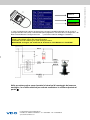
APPN 01/10
Istruzioni di montaggio
Sumlog® Viewline: adattamento al trasmettitore
analogico N01-140-302
it.vdo.com
Trasmettitore analogico N01-140-302
Cavi di prolunga: N05-801-846 (10mt)
N05-801-852 (20mt)
Connettore RJ45
VERDE
MARRONE
In caso di collegamento a sensori analogici (N01-140-302) è possibile utilizzare uno dei 2 cavi di
prolunga N05-801-846 (10mt) o N05-801-852 (20mt) tagliando il connettore RJ45 e collegando i 3 fili
Bianco-Verde-Marrone nel seguente modo:
(I colori sono riferiti al cablaggio IT-0054CA)
BIANCO: al filo GIALLO (pos.4) del Sumlog® Viewline
VERDE: al filo VERDE (pos.5) del Sumlog® Viewline
MARRONE: al filo BLU-NERO (pos.3) del Sumlog® Viewline
IMPORTANTE: Collegare una resistenza da 22 Kohm tra il filo BIANCO e il filo VERDE
Nelle prossime pagine sono riportate le istruzioni di montaggio del sensore
analogico, lo schema elettrico precedente sostituisce lo schema riportato al
punto \
Continental Automotive Trading Italia Srl
Via Vialba, 50 - 20026 Novate Milanese - Tel. +39 02356801 - Fax +39 0235680325
[email protected]
VDO è un marchio del Gruppo Contine ntal Automotive
BIANCO
INSTALLATION INSTRUCTIONS: Viewline 85 mm
Sumlog Sensor
TU00-0752-7307102
Safety information
• The product was developed, manufactured and inspected
according to the basic safety requirements of
EC Guidelines and state-of-the-art technology.
• The unit is designed for use in grounded vehicles and machines
as well as in nautical sports, including non-classified commercial
shipping.
• Use our product only as intended. Use of the product for reasons
other than its intended use may lead to personal injury, property
damage or environmental damage. Before installation, check the
vehicle documentation for vehicle type and any possible special
features!
• Use the assembly plan to learn the location of the fuel/hydraulic/
compressed air and electrical lines!
02/09
GB
1-4
No Smoking! No open fire or lights!
• The electrical indicator outputs and cables connected to them must
be protected from direct contact and damage. The cables in use
must have sufficient insulation and electric strength and the contact
points must be safe from touch.
• Use appropriate measures to also protect the electrically conductive
parts on the connected consumer from direct contact. Laying metallic, uninsulated cables and contacts is prohibited.
Safety after installation:
• Connect the ground cable tightly to the negative terminal of the
battery.
• Note possible modification to the vehicle, which must be considered
during installation!
• Reenter/reprogram the volatile electronic memory values.
• To prevent personal injury, property damage or environmental
damage, basic knowledge of motor vehicle/shipbuilding electronics
and mechanics is required.
• Use only clean water to clean the components. Note the Ingress
Protection (IP) ratings (IEC 60529).
• Make sure that the engine cannot start unintentionally during
installation!
• Modifications or manipulations to the VDO product can affect safety.
Consequently, you may not modify or manipulate
the product!
• When removing/installing seats, covers, etc., ensure that lines are
not damaged and plug-in connections are not loosened!
• Note all data from other installed units with volatile electronic
Safety during installation:
• During installation, ensure that the product’s components do not
affect or limit vehicle functions. Avoid damaging these components!
• Only install undamaged parts in a vehicle!
• During installation, ensure that the product does not impair the field
of vision and that it cannot impact the driver’s or passenger’s head!
• A specialized technician should install the product. If you install the
product yourself, wear appropriate work clothing. Do not wear loose
clothing, as it may get caught in moving parts. Protect long hair with
a hair net.
• When working on the on-board electronics, do not wear metallic or
conductive jewelry such as necklaces, bracelets, rings, etc.
• If work on a running engine is required, exercise extreme caution.
Wear only appropriate work clothing as you are at risk of personal
injury, resulting from being crushed or burned.
• Check all functions.
Electrical connection:
• Note cable cross-sectional area!
• Reducing the cable cross-sectional area leads to higher current
density, which can cause the cable cross-sectional area in question
to heat up!
• When installing electrical cable, use the provided cable ducts and
harnesses, however, do not run cables parallel to ignition cables or
to cables that lead to large electricity consumers.
• Fasten cables with cable ties or adhesive tape. Do not run cables
over moving parts. Do not attach cables to the steering column!
• Ensure that cables are not subject to tensile, compressive or
shearing forces.
• If cables are run through drill holes, protect them using rubber
sleeves or the like.
• Use only one cable stripper to strip the cable. Adjust the stripper
so that stranded wires are not damaged or separated.
• Only use a soft soldering process or commercially available crimp
connector to solder new cable connections!
• Only make crimp connections with cable crimping pliers. Follow the
safety instructions of the tool manufacturer.
• Insulate exposed stranded wires to prevent short circuits.
• Caution: Risk of short circuit if junctions are faulty or cables are
damaged.
• Before taking any action, disconnect the negative terminal on the
battery, otherwise you risk a short circuit. If the vehicle is supplied by
auxiliary batteries, you must also disconnect the negative terminals
on these batteries! Short circuits can cause fires, battery explosions
and damages to other electronic systems. Please note that when
you disconnect the battery, all volatile electronic memories lose their
input values and must be reprogrammed.
• Short circuits in the vehicle network can cause fires, battery explosions and damages to other electronic systems. Consequently,
all power supply cable connections must be provided with weldable
connectors and be sufficiently insulated.
• If working on gasoline boat motors, let the motor compartment fan
run before beginning work.
• If operating the instrument on power supply units, note that the
power supply unit must be stabilized and it must comply with the
following standard: DIN EN 61000, Parts 6-1 to 6-4.
• Pay attention to how lines and cable harnesses are laid so that you
do not drill or saw through them!
• Ensure ground connections are sound.
• Faulty connections can cause short circuits. Only connect cables
according to the electrical wiring diagram.
• Do not choose to install the product in the mechanical and electrical
airbag area!
• Do not drill holes or ports in load-bearing or stabilizing stays or tie
bars!
• When working underneath the vehicle, secure it according to the
specifications from the vehicle manufacturer.
TU00-0752-7307102
• Note the necessary clearance behind the drill hole or port at the
installation location. Required mounting depth: 65 mm.
• Drill small ports; enlarge and complete them, if necessary using
taper milling tools, saber saw, keyhole saw or file. Debur edges.
Follow the safety instructions of the tool manufacturer.
• Use only insulated tools, if work is necessary on live parts.
• Use only the multimeter or diode test lamps provided, to measure
voltages and currents in the vehicle/machine or ship. Use of conventional test lamps can cause damage to control units or other electronic systems.
Technische Änderungen vorbehalten - Technical details subject to change
1
INSTALLATION INSTRUCTIONS: Viewline 85 mm
Sumlog Sensor
1
TU00-0752-7307102
02/09
GB
1-4
2
Installation of the sending unit
The sending unit must be installed in a turbulence-free zone in the hull. If an echo sounder is installed, the Sumlog sending unit should be installed at the same height and to the side of, or laterally offset to the echosounder. Check for sufficient distance to stanchions, stringers, bulkheads, etc. when drilling the hull.
Do not install the sending unit close to external valves, anodes, etc. to avoid influences by turbulence.
2
Installation on sailing boats:
On sailing boats the sending unit should
always be installed in front of the keel, as
close to the longitudinal ship axis as possible.
On boats with a long keel the installation
should be at the end of the first third of the
hull, but not at the widest location of the hull.
Log sending unit
On powerboats the sending unit should be
installed at about the first third of the hull and
never towards the stern in a zone of strong
turbulence or up front, where strong disturbances by air induction must be expected.
An ideal installation is near the longitudinal
axis of the ship and in the zone of the first
stringer, directly in front of the engine compartment if possible. At higher speeds this is
the only location where a disturbancefree
operation can be expected..
Installation on powerboats:
First stringer
30 mm
Log sending unit
dia 39 mm
Make a hole 39 mm dia., at a suitable location. The wall thickness can
be up to 30 mm. Camber the hole out at 45 degrees for good sealant
distribution during the assembly. To install the hull sleeve and the sending unit proceed as follows:
1.
2.
3.
4.
Install flooding valve and sending unit:
5.
Put salt-water resistant sealant on the hull sleeve flange and introduce the sleeve from the outside into the hole.
From the inside, install the black sealing ring on the hull sleeve,
then the white one, and screw the fixation nut down.
Lightly hand-tighten the fixation nut at first. After letting the sealant
harden, tighten the nut another ¼ turn by hand and check the hull
feedthrough for leaks.
Put the loop of the control rope around the hull sleeve and knot the
loose end of the rope to the blind plug.
Screw the flood valve to the hull sleeve until an audible click indicates secure seating, is heard.
Insert the sending unit from the top and secure it with the nut.
5
Buw
TU00-0752-7307102
4
Note the correct direction when inserting the sending
unit. The pointed side of the sending unit loop must be
directed towards the bow as soon as the sending unit
has been inserted.
3
Technische Änderungen vorbehalten - Technical details subject to change
INSTALLATION INSTRUCTIONS: Viewline 85 mm
Sumlog Sensor
3
TU00-0752-7307102
02/09
GB
1-4
3
Removal of the sending unit
Loosen the union nut and pull the sending unit from the sleeve by rotating it slightly. Immediately insert the blind plug.
Never pull on the cable to remove the sending unit. Always use the loop.
Always insert the blind plug when the sending unit has been removed
4
Replacement of the paddle wheel
The paddle wheel of the sending unit is rotated
by the flow of water. The rotational speed of the paddle
wheel is measured without contacts, and transmitted to
the indicating instrument.
Use a screwdriver to replace the paddle wheel and its
shaft.
Carefully lift the paddle wheel shaft upwards to remove it
from the sending unit.
Insert the new shaft into the new paddle wheel and install
shaft and wheel, again using the screwdriver.
Bug
S
Check the correct installation direction when replacing
the paddle wheel. The spoon-shaped leading surface of
the wheel (A) must be directed towards the pointed side
of the loop (S).
The pointed side of the loop must be directed to the bow
when the sending unit is inserted in the hull sleeve.
A
Paddle wheel for indicating range
12 (kn, km/h, mph)
A
Paddle wheel for indicating range
30 and 50 (kn, km/h, mph)
A
TU00-0752-7307102
Technische Änderungen vorbehalten - Technical details subject to change
INSTALLATION INSTRUCTIONS: Viewline 85 mm
Sumlog Sensor
Connection to Viewline Sumlog
✄
5
TU00-0752-7307102
white
green
brown
02/09
GB
1-4
4
+12V
Sensor
minus
Remove the plug
Strip the individual lead
5
Calibration
After installation of the system your Viewline Sumlog must be calibrated to obtain speed and distance measurements with
the maximum accuracy.
On the Viewline Sumlog display, select the
setting for the die
function.
On the Viewline display, depending on the impeller being used, set the
value to one of the following pulse
numbers:
12 kn: 54737 Imp/nm
50 kn: 41748 Imp/nm
60 mph: 41748 Imp/nm
Mark two distinct points on the map. The distance between these two points defines the measuring length. During the trip
from one point to the other, the Viewline Sumlog measures the covered distance. In flowing waters it is necessary to make
the measuring run in both directions to compensate for the influence of the current.
2
(3 ,0
,7 nm
km
)
Measuring length:
Make a measuring run at a cruising speed, which remains as constant as possible.
Check that the trip distance counter is set to zero.
The following example refers to a measuring run in water without a current
with a measuring length of 2 nautical miles (nm).
Approach starting point A of the measuring length.
Set the trip distance counter to zero when passing starting point A.
Follow the measuring length on a straight line and note the indicated value
(1.7 nm in this example) when passing end point B.
Calculate the calibration factor C with the following formula:
Effectively covered distance (A-B)
2,0 nm
C= ------------------------------------------------------------ = ------------ = 1,18
Indication of the display (A-B)
1,7 nm
TU00-0752-7307102
Multiply the calculated value C by the pulse number set on the Viewline display and set the calculated result as the new
pulse number.
In the case of a measuring run in flowing water repeat the same distance measuring steps in the opposite direction (measuring length C-D).
The calibration factor is calculated with the following formula:
Effectively covered distance (A-B) + (C-D)
C= ----------------------------------------------------------------Indication of the display (A-B) + (C-D)
Do not use the GPS navigator as a reference for Viewline Sumlog calibration. The GPS Navigator indicates speed
over ground (SOG), but the Viewline Sumlog measures speed through water.
Technische Änderungen vorbehalten - Technical details subject to change