1
PowerGrid 9020
User Manual
Version A2.0, November 22, 2011
261072-017
Introduction
This user manual provides practical information for the installation, operation and
application of the device. It is suitable for those with little or no networking
experience, although some advanced topics are also covered.
A glossary of acronyms is included in Appendix A for reference.
Protect Our Environment
This symbol indicates that when the equipment has reached the end of
its useful life, it must be taken to a recycling centre and processed
separate from domestic waste.
The cardboard box, the plastic contained in the packaging, and the parts that
make up this router can be recycled in accordance with regionally established
regulations. Never dispose of this electronic equipment along with your
household waste. You may be subject to penalties or sanctions under the law.
Instead, ask for disposal instructions from your municipal government.
Copyright
Copyright© 2011 Comtrend Corporation. All rights reserved. The information
contained herein is proprietary to Comtrend Corporation. No part of this
document may be translated, transcribed, or reproduced in any form or by any
means without prior written permission of Comtrend Corporation.
NOTE:
This document is subject to change without notice.
1
Table of Contents
CHAPTER 1 - INTRODUCTION ........................................................................................................ 3
CHAPTER 2 - BASICS .......................................................................................................................... 4
2.1 VISUAL OVERVIEW .......................................................................................................................... 4
2.2 FRONT PANEL .................................................................................................................................. 5
2.3 DEFAULT SETTINGS ......................................................................................................................... 6
CHAPTER 3 - QUICK SETUP ............................................................................................................. 7
3.1 INTERNET CONNECTION .................................................................................................................. 7
3.2 DEVICE CONNECTION ...................................................................................................................... 8
3.3 POWER SAVING ................................................................................................................................ 8
CHAPTER 4 - NETWORK PERFORMANCE ................................................................................... 9
4.1 POINT-TO-POINT NETWORK ........................................................................................................... 10
4.2 POINT TO MULTIPOINT NETWORK .................................................................................................. 11
4.3 NEIGHBORING NETWORKS ............................................................................................................ 12
CHAPTER 5 - WEB USER INTERFACE ......................................................................................... 13
5.1 IP CONFIGURATION ........................................................................................................................ 13
5.1.1
Fixed IP .......................................................................................................................... 13
5.1.2
Isolation .......................................................................................................................... 16
5.2 LOGIN SCREEN .............................................................................................................................. 17
5.3 WUI HOMEPAGE ............................................................................................................................ 18
5.4 FURTHER INFORMATION ................................................................................................................ 20
5.5 CHANGE CONFIGURATION ............................................................................................................. 27
CHAPTER 6 - HELP ........................................................................................................................... 38
6.1 TROUBLESHOOTING ....................................................................................................................... 38
6.2 FAQ .............................................................................................................................................. 39
APPENDIX A - ACRONYMS ............................................................................................................. 40
2
Chapter 1 - Introduction
This user manual provides details concerning the installation, configuration and
application of COMTREND Corporation’s PowerGrid 9020 Powerline adapter.
The PowerGrid 9020 extends Ethernet (10/100M) networks over internal power
lines. It incorporates a power socket with AC filter, which allows for Powerline
networking without depriving the user of a single power outlet.
The front panel of the PowerGrid 9020 has one button and three LEDs that allow
the user to configure a secure network without the use of a computer. The Status
LED shows the amount of bandwidth (data transmission) available to applications.
A master PG9020 device cannot command more than 15 slave PG9020
connections in a network; therefore, 16 units of PG9020 is the maximum quantity
in a network.
If several IHAV networks are coexisting, there is a network isolation
protocol (Network ID) that ensures that no data from one network is received by
another network. In addition to the data isolation protocol, encryption can be
applied to protect data between networks.
SPECIAL FEATURES
One Button Security Setup - Automatic generation of an Encryption
Key and Network Identifier by pressing a single button!
Data Transmission Indicator – The tri-color Status LED shows the
amount of bandwidth (data transmission) available to applications.
Power Socket with AC Filter - Plug the PowerGrid 9020 into a power
outlet without losing use of the outlet for other applications.
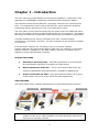
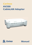
APPLICATIONS
The figure below shows example applications of Comtrend PowerGrid products.
NOTE:
PowerGrid 9020 units are fully compatible with all current and previous
models as well as any UPA-compliant (Universal Powerline Association)
device from 3rd party vendors
3
Chapter 2 - Basics
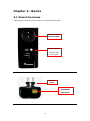
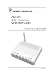
2.1 Visual Overview
These figures show the physical layout of the PowerGrid 9020.
Power Socket
with AC Filter
FRONT PANEL
1 Button and
3 LED lights
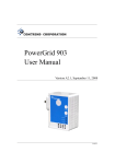
FIGURE 1 – FRONT VIEW
POWER
PLUG
ETHERNET
LAN PORT
FIGURE 2 – BOTTOM VIEW
4
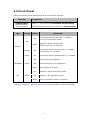
2.2 Front Panel
These two tables provide descriptions of the front panel interface.
BUTTON
FUNCTION
CONFIG/RESET
(Security Setup /
Factory Reset)
LED
COLOR
Press 1 ~ 10 seconds for One Button Security Setup.
Press 10 seconds (or more) to perform a Factory Reset.
MODE
On
FUNCTION
Connection speed is less than (<) 4 Mbps.
(or no PLC connection exists)
Red
Blink
STATUS
ETHERNET
Orange
On
Connection speed is greater than (>) 4 Mbps
and less than (<) 10 Mbps.
Green
On
Connection speed is greater than (>) 10 Mbps.
On
LAN connection established.
Off
LAN connection is not established.
Green
Blink
AP
Green
LAN connection is active.
On
Adapter in AP (Access Point) mode.
Off
Adapter in EP (End Point) mode
Blink
Adapter in power saving mode
(blinks twice every 5 seconds)
Secure connection setup in progress.
Refer to Chapter 4 - Network Performance for more about connection speeds.
5
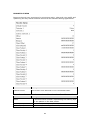
2.3 Default Settings
The factory default settings are presented below.
•
Authentication password = paterna
•
Factory Reset password = betera
•
Factory Reset time = 10 seconds
•
IP Configuration = FIXED
•
FIXED IP address = 192.168.1.100
•
FIXED IP subnet mask = 255.255.255.0
•
Default Gateway IP address = 192.168.1.105
•
DNS Server IP address = 192.168.10.252
•
Network Identifier = Serial Number of AP Unit
•
Encryption Key = This field is empty
•
Encryption Type = 3DES (168-bit)
•
Automatic Multicast = Disabled
•
IGMP Aware Multicast = Disabled
•
MLD Aware Multicast Syndication = Disabled
•
Video Optimization = Automatic
•
Priority (QoS) Configuration = UDP Priority 5, TCP Priority 0 (Default=4)
•
VLAN Configuration = Disabled
•
PHY – Notches = Enabled
•
PHY – Power Control = Enabled
•
Power Saving = Enabled (300 second delay)
•
Link Layer Topology Discovery (LLTD) = Enabled
NOTE:
These configuration settings can be customized using a web browser.
For further instructions, see Chapter 5 - Web User Interface. To return
the adapter to factory default settings, follow the FACTORY RESET
procedure in the Troubleshooting section of this manual.
6
Chapter 3 - Quick Setup
This section is subdivided into three parts:
•
•
Sections 3.1 and 3.2 contain the setup procedures.
Section 3.3 provides a description of the power saving feature.
NOTE:
A single PowerGrid 9020 unit and Ethernet cable are required for each
device (e.g. PC, modem/router) you wish to connect to the network.
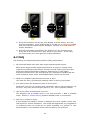
3.1 Internet Connection
These steps show how to connect a PowerGrid 9020 unit to a modem or router.
1. Turn on your modem or router.
2. Plug a PowerGrid
9020 unit into the
power socket closest
to the modem/
router. The STATUS
LED on the front
panel of the
PowerGrid 9020
should light up RED.
3. If the AP LED is GREEN continue to step 4. If not,
go back to step 2 and try the other PowerGrid 9020
unit.
4. Connect the PowerGrid 9020 unit to the LAN port of
the modem/router with an Ethernet (RJ-45) cable.
The Ethernet LED on the unit should light up
GREEN.
7
3.2 Device Connection
These steps show how to connect a PowerGrid 9020 to any network device.
In this case, we use the example of a personal computer (PC).
1. Turn on your PC (or other device).
2. Plug a PowerGrid 9020 unit into the power socket closest to the PC.
The Status LED on the PowerGrid 9020 should light up.
3. Connect the PowerGrid 9020 to the computer with an Ethernet cable.
The Ethernet LED on the PowerGrid 9020 should light up GREEN.
4. The STATUS LED on the PowerGrid 9020 should now be GREEN or ORANGE.
If it is not, please consult Chapter 6 - HELP.
3.3 Power Saving
These units have a smart power saving mode for energy conservation. They will
enter power saving mode if there is no Ethernet link detected within a 5 minute
period, and assuming that the unit is not required for Powerline routing.
For greater power savings, you can also unplug PowerGrid 9020 units. You may
consider doing so, if you are going on holiday or a business trip for an extended
period. These units keep their network security settings even after losing power,
so that you do not need to worry about losing network settings. This feature is
especially useful when moving networked devices or after a power outage.
8
Chapter 4 - Network Performance
The Status LED shows an estimate of available throughput in the application layer.
There are three levels of throughput indicated by three different LED colors. A
particular adapter shows, with one color, the throughput level with reference to
the adapter sending the most data to it. In the case of a network consisting of
two adapters, they always show the level of throughput with reference to the
other.
However, in the case of a network of three or more adapters, each one internally
measures the amount of bytes received from the other adapters in the network
and only shows the level of throughput with reference to the one that is sending
the most data. A throughput estimator also keeps track of the number of
neighboring networks since available bandwidth will be divided between them
when sharing the channel. The thresholds for these levels of throughput are
preconfigured in the system.
The STATUS LED behavior is summarized in the table below.
LED
STATUS
RED
Estimated Throughput < Low Threshold (4 Mbps)
ORANGE
Low Threshold (4 Mbps) <
Estimated Throughput
< High Threshold (10 Mbps)
GREEN
Estimated Throughput >
High Threshold (10 Mbps)
9
4.1 Point-to-Point Network
•
CASE 1: Estimated throughput is less than 4 Mbps. The PLC channel is not
able to transmit an SDTV channel. The STATUS LED will be RED as shown
in the following figure:
•
CASE 2: Estimated throughput is greater than 4 Mbps but less than 10
Mbps. The PLC channel is able to transmit an SDTV channel, but not two
SDTV channels simultaneously or one HDTV channel. The STATUS LED will
be ORANGE as shown in the following figure:
•
CASE 3: Estimated throughput is greater than 10 Mbps. The PLC channel
is able to play at least two SDTV channels or 1 HDTV. The STATUS LED will
be GREEN as shown here:
10
4.2 Point to Multipoint Network
In the case where the PLC network is composed of three or more adapters,
similar situations could arise as with a point-to-point network. These are
illustrated in the following figures:
The STATUS LED in each adapter will show the estimated level of the PLC link
from which it is receiving the most amount of traffic at any given time. The status
LED in PLC adapter 3, for example, could be showing a level of throughput
available from PLC adapter 2 for a period of time as illustrated in the figure above.
However, traffic flow could change through user intervention and then the status
LED in PLC adapter 3 could show the level with reference to the PLC adapter 1
link, as shown in the following figure.
11
4.3 Neighboring Networks
The Status LED also takes into account the possibility of having neighboring
networks. In such a case, the throughput evaluator will divide the available
bandwidth in two when there is visibility between any two networks since the PLC
channel must be shared on a time basis. In the following figure, an example of an
isolated network is first shown.
In the next figure, the previous network (network 1) sees a new neighboring
network (network 2), and a new evaluation of throughput is made to show the
user that channel conditions have changed and available bandwidth has
decreased:
12
Chapter 5 - Web User Interface
The web-based user interface (WUI) provides access to information about your
PowerGrid 9020 units and can also be used to configure or reset device settings.
The WUI is accessed using a web browser, such as Microsoft Internet Explorer.
The following instructions assume that the PowerGrid network has been
configured correctly (i.e. according to the instructions in Chapter 3) and that the
host computer is running Windows XP.
NOTE:
The process described in the following sections will work for any
operating system (OS), but the specific steps will need to be adjusted to
match your particular computing environment.
5.1 IP Configuration
Before using the WUI, you first need to adjust the IP configuration of the host PC.
This is a two-step process addressed in subsections 5.1.1 and 5.1.2.
FYI:
The IP configuration defines the location of your computer within the
network using Internet Protocol (IP) addressing. Your computer needs
an IP address so it can receive and send information on the network.
In Fixed IP mode you assign this IP address yourself; while in DHCP
mode it is assigned automatically by a DHCP server.
5.1.1 Fixed IP
The following instructions describe how to change the IP configuration of your
computer to FIXED IP mode, so that you can access the WUI.
STEP 1: Turn on your computer (and login, if necessary).
13
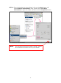
STEP 2: From the desktop (as shown below), click on the Start button and
select Network Connections. Next, double-click Local Area
Connections to open its window and then click the Properties button.
NOTE:
You may also access this window by double-clicking
the Local Area Connection icon on your taskbar.
14
STEP 3: Select Internet Protocol (TCP/IP) and click the Properties button.
STEP 4: Check the settings in the Internet Protocol (TCP/IP) Properties
dialog box (shown on the far right in the figure above). Make sure to
record all the settings you see here, as you may need to reset them.
STEP 5: If the “Obtain an IP address automatically” radio button is selected,
then your PC is configured in DHCP mode. You should select the “Use
the following IP address” radio button to enter FIXED IP mode.
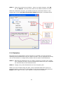
STEP 6: Change the IP address, Subnet Mask and Default Gateway to
match those values shown in the figure below and click the OK button.
Click OK
15
STEP 7: Close the previous two windows. Since you made changes, click OK,
but not Cancel! You then must wait for the LAN connection to reset.
After the connection recovers, you should check the connection status on the
support tab of the Local Area Connection Status dialog box, as shown below.
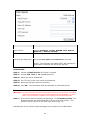
5.1.2 Isolation
Now that the IP configuration of the computer is complete, we will proceed by
isolating the PowerGrid 9020 unit you wish to access. This is required since every
unit on the network is configured by default with the same Fixed IP address.
STEP 1: Relocate the PowerGrid unit you wish to access to a power jack nearby
your computer and then connect the Ethernet cable from your computer
(or network hub) to this PowerGrid unit.
STEP 2: Unplug every other PowerGrid unit from its power jack.
When you have finished using the WUI, return the PowerGrid 9020 unit to its
previous location, reset the IP configuration of the host computer, and press the
Repair button again to return your system to its previous condition.
16
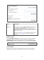
5.2 Login Screen
Perform the following steps to login to the WUI:
STEP 1:
Start the Internet browser and enter the IP address as a HTTP link
in the URL address field and press Enter. For the default IP
address of 192.168.1.100, you must input http://192.168.1.100,
as shown below.
STEP 2: The login screen should appear, as shown below. Enter the login
password in the top section and click OK to continue. To perform a
factory reset on the device you must enter the factory reset password
in the bottom section and click OK. The WUI login password and other
default settings can be found in section 2.3.
NOTE:
You can change this password in the WUI (see Security in section 5.5).
17
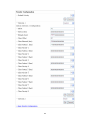
5.3 WUI homepage
If login is successful, you will arrive at the WUI homepage. This screen provides
summary information concerning the PowerGrid 9020 and its connections. It also
provides access to the Further Information and Change Configuration screens
discussed in sections 5.4 and 5.5.
See the table below for details.
18
Available Connections
PLC Connections
The total number of PowerGrid units in the network.
PLC PORT
The PLC data connection port for each connection.
MAC Address
This is a code that identifies all remote devices
connected to this unit. On PowerGrid units, it is printed
on the back label under the barcode.
Phy Tx/Rx Throughput
Physical Transmission / Reception Throughput is a
measure of network bandwidth. Available data
transmission capacity is roughly half this value.
Bridge State
Enabled indicates there is a data connection.
Disabled indicates no data connection.
Network Id
Network ID is used for network security. If present, it
means the remote device is on the same network.
External Interfaces
Interface
EXTA = Ethernet
Phy Throughput
Physical Throughput = Data Transmission Capacity
Bridge State
Forwarding = Active
General Information
MAC Type
The MAC Address shown above is an In-Home AV type.
MAC Address
This code identifies the PowerGrid unit that is currently
being managed with the WUI. The MAC Address is
printed on the back label of the unit, under the barcode.
IP Address
The IP Address defines the location of the PowerGrid
unit on the local area network.
Node Type
This will show as Fixed AP, EP or AP.
Number of Boots
The number of times this PowerGrid unit has been
rebooted since the last Factory Reset.
NOTE: The remaining fields are advanced settings used for technical support.
19
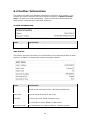
5.4 Further Information
This screen provides more detailed information concerning your network. It is
divided into various sections with each section divided by a “Return to main
page” link back to the WUI homepage. These sections are shown below and
each section is followed by a table that explains it.
SYSTEM INFORMATION
Field
Description
Uptime
This shows the length of time the PowerGrid unit has been on.
Firmware Version
This shows the PowerGrid installed firmware version.
MAC STATUS
This section provides information for identification of the PowerGrid 9020 by MAC
Address, in addition to PowerGrid network encryption details.
Field
Description
MAC Address
This is a code that identifies each PowerGrid unit. It can be
found on the back label of the unit below the barcode.
MAC Type
In-Home AV is the only option at this time.
Node Type
This will show as Fixed AP, EP or AP.
Network
Identifier
This field is used to identify the network.
It can be up to 20 ASCII characters long.
Encryption Key
This key is used to encrypt the network.
It is encoded in either ASCII or HEX format.
Encryption Type
The possibilities are 168 bit 3DES or 128/256 bit AES.
20
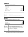
NETWORK STATUS
This section shows the current IP configuration.
Field
Description
IP Configuration
Either DHCP (Automated) or Fixed (Manual)
IP Address /
Subnet Mask
These values define the location of the PowerGrid unit on the
local area network.
Default Gateway
IP Address
The IP address of the router that forwards traffic to a
destination that is out of reach of the PowerGrid unit.
DNS server
IP Address
The IP address of the server that provides Domain Name
System (DNS) services such as hostname IP lookup.
PHY STATUS
This section summarizes the physical parameters of the network.
Field
Description
Notches
Radio-frequency (RF) interference reduction.
Power Control
This function minimizes the transmission power of each
PowerGrid unit while maintaining data throughput performance.
*Dynamic PSD
Control
The modem’s Ethernet port monitors the incoming traffic rate
and subsequently calculates the transmission power required
that permits this rate of transmission.
The higher the incoming traffic rate, the greater the phy rate
and transmission power required. The lower the rate, the lesser
the phy rate and transmission power required.
*
This feature has been developed to reduce the transmission power so as to
cut the power consumption of the device and minimize the interference to
other electronic devices in the vicinity.
21
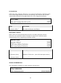
LLTD STATUS
LLTD (Link Layer Topology Discovery) is a protocol supported by Windows Vista.
LLTD enables applications to discover the topology of a network and includes
optional QoS Extensions that applications can use to diagnose problems.
Field
Description
Link Layer Topology
Discovery (LLTD)
When enabled, multicasting is limited to either IGMP or
MLD Aware Multicast Syndication.
MULTICAST STATUS
IGMP (Internet Group Membership Protocol) and MLD (Multicast Listener
Discovery) are protocols used by IP hosts to report their multicast group
memberships to any neighboring multicast routers.
Field
Description
Automatic Multicast
Auto-configures the local network for multicasting.
IGMP Aware Multicast
Syndication (IPv4)
Multicasting for IPv4 networks. Enabled in EP mode.
Disabled in AP mode. (See LLTD description above)
MLD Aware Multicast
Syndication (IPv6)
Multicasting for IPv6 networks.
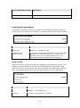
VIDEO OPTIMIZATION
The optimization strategy for video streams is shown here.
22
Video Optimization Mode
Description
Automatic Optimization
Optimization based on video traffic type (TCP or UDP).
Optimized for Media Player
Improved transmission of TCP video.
Optimized for IPTV Service
Improved transmission of UDP video.
POWERSAVING MECHANISM
This function activates a low power mode when the PowerGrid 9020 is inactive,
unless that unit is assigned as a master or repeater within the Powerline network.
Field
Description
PowerSaving
mechanism
Enabled = PowerSaving On
Disabled = PowerSaving Off
Hysteresis time
(Ethernet Link)
PowerSaving mode becomes active when it is Enabled
and there is no Ethernet Link for {x} number of
seconds, where {x} is the Hysteresis time. It is
inactivated when an Ethernet Link is detected.
VLAN STATUS
With this function an 802.1Q VLAN Tag is added to the data packet header. This
enables a physical LAN to be divided into several discrete virtual LANs. Data
packets are given priority based upon their VLAN Tag and VLAN Priority settings.
Note, the PowerGrid 9020 does not filter data packets; it merely tags them.
Field
Description
VLAN Configuration
Enabled = VLAN tagging on
Disabled = VLAN tagging off
VLAN Tag
A number in the range of 2 to 4094.
VLAN Priority
A number between 0 and 7 (highest priority).
23
PRIORITY STATUS
Improve the end-user experience by prioritizing audio, video and voice traffic and
optimizing the way shared network resources are allocated among applications.
Field
Description
Default Priority
The priority level assigned to non-prioritized traffic.
Criteria (1 & 2)
None, Custom, 8021p, TOS, ARP, TCP_8021p, or TCP_TOS
Custom Criterion 1:
Description
Offset
A decimal ordinal number representing the starting byte
for the pattern in the data packet.
Pattern (hex)
Defines the pattern (8-byte size).
Bitmask (hex)
A bitwise operation applied to the pattern.
24
Class Offset
A decimal ordinal number representing the starting byte
for the class pattern in the data packet.
Class Bitmask(hex)
A bitwise operation applied to Class Patterns 1-8.
Class Pattern 1-8 (hex)
Defines a class pattern (8-byte size).
Class Priority 1-8
This value ranges from 0 to 7, with 0 being the lowest
priority and 7 the highest priority.
25
SECURITY STATUS
This section shows the current login password requirement status.
Field
Description
Status
Password is currently installed / No password installed
26
5.5 Change Configuration
This screen provides various configuration options with each section divided by a
“Return to main page” link back to the WUI homepage. These sections are
shown below and each section is followed by a table that explains it.
MAC CONFIGURATION
This section provides options to configure the PowerGrid 9020 MAC characteristics
and network encryption mode.
Field
Description
MAC Type
In-Home AV is the only option at this time.
Node Type
Choose Fixed AP or EP.
Network
Identifier
This field is used to identify the network.
It can be up to 20 ASCII characters long.
Encryption Key
This key is used to encrypt the network.
It is encoded in either ASCII or HEX format.
Encryption Type
The possibilities are 168 bit 3DES or 128/256 bit AES.
AES Key Length
AES encryption can be set as 128 or 256 bit strength.
NOTES:
In 3DES mode, the Encryption Key can be up to 24 ASCII characters or 42
hexadecimal numbers. In AES mode, it can be up to 36 ASCII characters or 64
hexadecimal numbers (256 bit mode). Hexadecimal encryption is stronger.
27
NETWORK CONFIGURATION
The section provides options to configure the IP configuration.
Field
Description
IP Configuration
Either DHCP (Automated) or FIXED IP (Manual).
NOTE: In FIXED mode the IP Address, Subnet Mask and Default Gateway IP
Address can be set manually, while in DHCP mode they are assigned by a server.
Changes do not become effective until after a reboot of the PowerGrid unit.
IP Address /
Subnet Mask
These values define the location of the PowerGrid unit on the
local area network.
Default Gateway
IP Address
The IP address of the router that forwards traffic to a
destination that is out of reach of the PowerGrid unit.
DNS server
IP Address
The IP address of the server that provides Domain Name
System (DNS) services such as hostname IP lookup.
PHY CONFIGURATION
This section provides options to configure the physical parameters of the network.
28
Field
Description
Notches
RF interference reduction is disabled by default.
Power Control
This function minimizes the transmission power of each
PowerGrid unit while maintaining data throughput performance.
*Dynamic
PSD Control
The modem’s Ethernet port monitors the incoming traffic rate
and subsequently calculates the transmission power required that
permits this rate of transmission.
The higher the incoming traffic rate, the greater the phy rate and
transmission power required. The lower the rate, the lesser the
phy rate and transmission power required.
*
This feature has been developed to reduce the transmission power so as to
cut the power consumption of the device and minimize the interference to
other electronic devices in the vicinity.
LLTD CONFIGURATION
LLTD (Link Layer Topology Discovery) is a protocol supported by Windows Vista.
LLTD enables applications to discover the topology of a network and includes
optional QoS Extensions that applications can use to diagnose problems.
Field
Description
Link Layer Topology
Discovery (LLTD)
When enabled, multicasting is limited to either IGMP or
MLD Aware Multicast Syndication.
MULTICAST CONFIGURATION
IGMP (Internet Group Membership Protocol) and MLD (Multicast Listener
Discovery) are protocols used by IP hosts to report their multicast group
memberships to any neighboring multicast routers.
29
Field
Description
Automatic Multicast
Auto-configures the local network for multicasting.
IGMP Aware Multicast
Syndication (IPv4)
Multicasting for IPv4 networks. Enabled in EP mode.
Disabled in AP mode. (See LLTD description above)
MLD Aware Multicast
Syndication (IPv6)
Multicasting for IPv6 networks.
VIDEO OPTIMIZATION
Select an optimization strategy for video streams.
Video Optimization Mode
Description
Automatic Optimization
Optimization based on video traffic type (TCP or UDP).
Optimized for Media Player
Improved transmission of TCP video.
Optimized for IPTV Service
Improved transmission of UDP video.
POWERSAVING MECHANISM
This function activates a low power mode when the PowerGrid 9020 is inactive,
unless that unit is assigned as a master or repeater within the Powerline network.
Field
Description
PowerSaving
mechanism
Enabled = PowerSaving On
Disabled = PowerSaving Off
Hysteresis time
(Ethernet Link)
PowerSaving mode becomes active when it is Enabled
and there is no Ethernet Link for {x} number of
seconds, where {x} is the Hysteresis time. It is
inactivated when an Ethernet Link is detected.
30
VLAN STATUS
With this function an 802.1Q VLAN Tag is added to the data packet header. This
enables a physical LAN to be divided into several discrete virtual LANs. Data
packets are given priority based upon their VLAN Tag and VLAN Priority settings.
Note, the PowerGrid 9020 does not filter data packets; it merely tags them.
Field
Description
VLAN Configuration
Enabled = VLAN tagging on
Disabled = VLAN tagging off
VLAN Tag
Choose a number in the range of 2 to 4094.
VLAN Priority
Choose a number between 0 and 7 (highest priority).
PRIORITY STATUS
Improve the end-user experience by prioritizing audio, video and voice traffic and
optimizing the way shared network resources are allocated among applications.
31
32
The table below provides details about the section shown in figure above.
Field
Description
Default Priority
The priority level assigned to non-prioritized traffic.
Criteria (1 & 2)
None, Custom, 8021p, TOS, ARP, TCP_8021p, or TCP_TOS
The QoS criteria are applied as follows:
a) Criterion 1 is processed first (and Criterion 2 second)
b) If Criterion 1 is met, Criterion 2 will NOT be applied
Thus, Criterion 2 should be more general than Criterion 1. There are also certain
incompatibilities that arise between these criteria, as outlined in the table below.
If Criterion 1 Protocol is …
Then Criterion 2 can be …
Origin IP / Destination IP
None of these protocols.
TCP with port
UDP Protocol, Origin and destination IP
address for UDP packets
UDP with port
TCP Protocol, Origin and destination IP
address for TCP packets
Custom Criterion Configuration
Offset
A decimal ordinal number representing the starting
byte for the pattern in the data packet.
Pattern (hex)
Defines the pattern (8-byte size).
Bitmask (hex)
A bitwise operation applied to the pattern.
Class Offset
A decimal ordinal number representing the starting
byte for the class pattern in the data packet.
Class Bitmask (hex)
A bitwise operation applied to Class Patterns 1-8.
Class Pattern 1-8 (hex)
Defines a class pattern (8-byte size).
Class Priority 1-8
This value ranges from 0 to 7, with 0 being the
lowest priority and 7 the highest priority.
SECURITY STATUS
This section allows you to change (or remove) the configuration password, used
to access the WUI, and perform a factory reset to recover default settings.
33
Field
Description
Status
Password is currently installed / No password installed
Set Configuration
Password
To change the configuration password, notice that you must
enter it twice; first in the New password field and again in
the Confirm new password field. The configuration
password can be up to 20 characters in length. To remove
the configuration password, leave these fields empty. Click
OK to make a change.
Factory Reset
To reset the device to factory settings, enter the factory reset
password (see section 2.3) and click OK. Use this function
with caution, as it will erase the current configuration
settings.
HARDWARE RESET
Press the Hardware Reset button to reboot the device. It will not erase the
configuration settings. It performs the same function as holding down the
CONFIG/RESET button for 10 seconds or more. You must perform a hardware
reset of the device to change some settings, such as IP mode (DHCP/FIXED).
FLASH UPGRADE
Flash memory is divided into six separate sections which can be upgraded
independent of each other using FTP, TFTP or L2 (Layer 2) server protocols.
34
Field
Description
Status
Reports the current status of the flash upgrade.
Flash section
Choose Firmware, Loader, NVRAM, DSP, Analog
Symbols or Factory settings.
Upgrade Protocol
Choose FTP, TFTP or L2 protocol.
Server IP Address
Input the IP address of the FTP or TFTP server.
FTP User and Password
Input the user name and password if required
Filename
This is the filename of the flash upgrade on the
server. The firmware and loader have .bin extensions,
while factory settings are stored as .cfg files.
PROCEDURE:
STEP 1: Choose a Flash Section (File Type) to upload.
STEP 2: Choose FTP, TFTP or L2 upgrade protocol.
STEP 3: Enter the Server IP Address.
STEP 4: For FTP only, enter User name and Password.
STEP 5: Enter the Filename with file extension
STEP 6: Click OK. The PowerGrid 9020 will attempt to download the file.
Warning! Do not interrupt the download progress once it has started! The flash
memory will become corrupt and the device will be disabled. In this
case, you will need to contact your supplier for technical support.
STEP 7: Once the file has successfully downloaded. Click Hardware Reset. The
PowerGrid 9020 will reboot and then load the new flash section. The
browser should refresh to the WUI login screen (pg. 17).
Explanations of the various status messages are provided in the table below.
35
Flash Upgrade Status Failed
This status message means the upgrade was not successful.
Click the back button on your browser and check settings before trying again.
If the file upload fails, we recommend the following:
(1) Once you have decided on the file you want to upload (firmware or factory
setting), make sure the name is correct and there are no typing errors.
Also, ensure that the file (name) and the required flash section match.
(2) Make sure that the TFTP or FTP server is ready for upgrade. If the user
runs TFTP server, select TFTP (from the dropdown menu) for the upgrade
protocol. If the user runs FTP server, select FTP (from the dropdown
menu) for the upgrade protocol.
(3) Be sure that the server IP address that you input is the IP address of the
TFTP or FTP “server” not your PG-9020’s IP address. Also, check that the
IP configuration of the PG-9020 is on the same network segment as the
server (see IP Configuration for details).
(4) The file required for upgrade needs to be placed in a folder/directory that
the TFTP/FTP server can access.
(5) For FTP Server: Make sure that the correct User Name and Password are
inputted.
36
DOWNLOADING
This status message indicates that the file has been successfully located on the
server. You can watch the Download Progress at the bottom of this section. The
browser will automatically refresh every 30 seconds; but to check the download
progress more frequently, you can manually refresh the browser at any time.
UPGRADE SUCCESSFUL
If the upgrade was successful the status message will display as shown below.
37
Chapter 6 - HELP
The PowerGrid 9020 has been designed to be a reliable and easy-to-use home
networking device. However, should you experience any problems, please refer to
the troubleshooting and FAQ sections below to resolve your issue.
6.1 Troubleshooting
Please consult the following procedures to resolve your current issue. The first
two sections (steps A-C) provide general procedures that are used in later steps.
FACTORY RESET
A. To reset a unit to factory default settings, press the CONFIG/RESET button
for 10 seconds or more. The PowerGrid 9020 will then reset its configuration
to factory default settings and auto-reboot.
The PowerGrid 9020 is set as an EP after the factory reset. (When you will do
the reset on AP, this configuration disappears and unit will be back us the EP.)
When you will plug PowerGrid 9020 back into the network, you have to do the
“pairing”. Description in QSG, Part C. Adding a Third PowerGrid 9020.
i.
Please press the CONFIG/RESET button on the unit already in network, AP
LED starts blinking, and then release it. You now have thirty (30) seconds
to complete the EP set up.
ii. Before the unit AP LED stops blinking, press the CONFIG/RESET button on
the EP unit. Wait for its AP LED to start blinking and then release the
button. After a few seconds, the AP LED (on 3rd PowerGrid 9020) should
flash quickly and then turn OFF.
iii. After adding the EP unit to the PowerGrid network, check that the AP LED
on the AP unit has stopped blinking and remains ON.
ISSUE #1: POOR NETWORK PERFORMANCE
B. If the network is performing slowly or not at all, do the following.
i.
Confirm that your networked devices are turned ON and working correctly.
ii. Check the ETHERNET LED on every PowerGrid 9020. The ETHERNET LED
on every unit should be GREEN. If the ETHERNET LED on any unit is OFF,
check that the ETHERNET cable is connected securely.
iii. Check the STATUS LED of every unit. The STATUS LED color should be
ORANGE or GREEN. Perform a FACTORY RESET (see step A) on any
units with a RED STATUS LED.
ISSUE #2: HOME WIRING
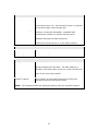
C. If the previous steps were unsuccessful, your home wiring may be at fault. To
test this possibility, repeat the following steps on the EP unit.
i.
Unplug the EP unit from the power outlet, detach the Ethernet cable, and
relocate the EP unit close to the AP unit (i.e. within the same room).
ii. Perform a FACTORY RESET (see step A) on the EP unit.
38
iii. If the LED indicators on the two units display as shown above, then the
test was successful. If the STATUS LED on the EP unit is ORANGE or RED
then the PowerGrid 9020 may be damaged. Contact your local agent for
further assistance.
iv. If the EP unit tested successfully, the problem you are experiencing is
likely due to RF interference or poor wiring in your home. In this case,
you can contact your local agent for further assistance.
6.2 FAQ
The following are frequently asked questions (FAQ) and answers.
1. Do PowerGrid 9020 units work with surge protected power strips?
Basic power strips provide simple protection for a surges in voltage. More
expensive models have this feature, but also include a filter which provides
protection against EMI (Electro-Magnetic Interference) or RFI (Radio
Frequency Interference). Our test lab and user experience indicates that the
more expensive strips, those with EMI/RFI filters, should not be used.
2. What if my neighbor has Powerline devices as well?
You need not worry as PowerGrid network traffic is securely encrypted.
3. Is it safe to leave the PowerGrid units on all the time?
PowerGrid units are CE certified and completely safe to leave plugged in all
the time. They may become slightly warm in use - this is perfectly normal.
3. How much power do PowerGrid units use?
The Adapters use 4.4 Watts when in use and less than 1 Watt in standby
mode. Section 3.3 Power Saving explains standby mode in more detail.
4. Who can I contact for help?
If this chapter has failed to resolve or address your issue, please consult your
local agent for further assistance. We would also appreciate any suggestions
or comments that you would like to share regarding our product or user
documentation. Your feedback will be used to improve our products.
39
Appendix A - Acronyms
The following list of acronyms is provided for your reference.
ACRONYM
EXPANDED
3DES
Triple DES
AES
Advanced Encryption Standard
AP
Access Point
DES
Data Encryption Standard
EP
End Point
HDTV
High Definition TV
ISP
Internet Service Provider
PC
Personal Computer
PowerGrid
Comtrend brand name
SDTV
Standard Definition TV
STB
Set Top Box
WUI
Web User Interface
40