1
DC-150
Counting Scale
When Accuracy Counts
Operation Manual
73346
GENERAL SPECIFICATIONS
1.1 MODE FLOW CHART
1.2 SPECIFICATION
1.3 OVERALL VIEW
1.4 LABEL FORMAT AND LABEL SET UP
1.5 GENERAL EXPLANATION
opermode.doc 9/4/98
1
SECTION 1.
1.0
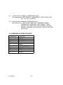
OPERATION MODE − TABLE OF CONTENTS
PAGE
GENERAL
3
DESCRIPTION
3
1.1
MODE FLOW CHART
4
1.2
SPECIFICATION
5-7
1.3.1
OVERALL VIEW
8&9
1.3.2
DISPLAY & KEYS
10
1.3.3
KEY FUNCTION IN OPERATION MODE
11-13
1.4
LABEL FORMAT AND LABEL SET UP
14 - 15
1.5
GENERAL EXPLANATION OF SHELF LOCATION & SET POINT
16 - 17
1.5.3
UNLOCKING PROCEDURE
18
1.5.3
SOFTWARE VERSION RECALL
19
1.5.7
UNIT WEIGHT ENTRY BY SAMPLING
20
1.5.8
UNIT WEIGHT ENTRY BY NUMERIC KEYS
21
TARE WEIGHT ENTRY
22
1.6.1
ONE TOUCH TARE ENTRY
22
1.6.2
TARE ENTRY BY NUMERIC KEYS
22
1.7
PART NO. ENTRY
23
1.8
PART NAME
23
1.9
LOT NO. ENTRY
24
PRINTER TURN OFF/ON
24
1.10
SEQUENCE NO. ENTRY
25
1.11
ID CODE ENTRY
25
1.12
PARTS COUNTING OPERATION
26
1.12.1
SINGLE TRANSACTION
26
1.12.2
MULTIPLE TRANSACTION
27
1.13
BATCH LABEL PRINT
28
1.14
SELECTING LABEL FORMAT
29
ADDRESS DATA ENTRY
29
1.15
GROSS WEIGHT DISPLAY
30
1.16
AUTO JOB OPERATION MODE
31 - 31
1.0.1
1.6
1.9.2
1.14.1
2
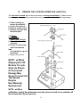
1.0. GENERAL
1.0.1
DESCRIPTION
The DC-150 counting scale offers a practical solution to a full range
of precision counting applications. There are a variety of models
available ranging from a weight capability of 0.5 lb. through 100 lb.
utilizing an internally mounted load cell and a full range from 0.5 to
50,000 lb. on an external second or third channel. A console model
is also available with 1 or 2 external platforms in any of the above
mentioned capacities in any combination.
This instruction manual will provide the user with all the information
necessary to understand, set-up and operate the DC-150 scale.
Included in this manual are descriptions, specifications, drawings,
and operating instructions.
3
1. MODE FLOW CHART
OPERATION MODE
Receiving Operation (Manual / Auto Job Operation)
Shipping Operation (Manual / Auto Job Operation)
Checking Operation (Manual / Auto Job Operation)
PROGRAM MODE
ID Code Programming
Date & Time Setting
Set Point Setting
Field Titles Programming (No.1 ~ No.16 titles)
Pre-printing Name Programming
Format Copy (No.1 ~ No.7 Formats)
Free Format Programming ( 2 Formats)
Shelf Location Label Programming
Shelf Location Limit - Range Setting
Address Label Programming
CHECK MODE
Check Memory Files - Free Addresses
Check Inventory Data - Print Reports
Shelf Location Label - Print Labels
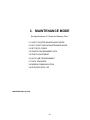
MAINTENANCE MODE
Set SPEC Codes - Capacity, Operation, Printing
Memory Deletion - Inventory, formats
Print Adjustment - Contract, Feed
Auto Job Operation Pattern Setting
Data Transfer - Spec Codes, Formats, Inventory
Modem Communication
Printing SPEC List
Attaching Other Devices
4
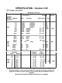
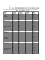
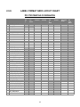
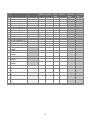
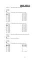
SPECIFICATION - Version 2.00
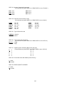
1.1
MODEL CAPACITIES
All Weight in Pounds
Resolutions
Optional
MODEL Capacity
Apparatus
0.5
1.0
2.5
5.0
10.0
25.0
50.0
100.0
151L
Platform
Wgt.
Counting
Dimensions
0.0001
0.0001
0.0002
0.0005
0.001
0.002
0.005
0.01
0.000001
0.000002
0.000005
0.00001
0.00002
0.00005
0.0001
0.0002
Remote
Scale
6” x 8”
6” x 8”
7” x 10”
12” x 14”
12” x 14”
NO
12” x 14”
12” x 14”
12” x 14”
YES
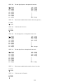
REMOTE PLATFORMS
152L
YES
&
153L
250.0
500.0
1000.0
2500.0
5000.0
10000.
25000.
50000.
Capacity
Scale 1 Scale 2
0.5
1.0
1.0
1.0
1.0
2.5
2.5
2.5
0.02
0.05
0.1
0.5
1.0
2.0
5.0
0.0005
0.001
0.002
0.2
0.005
0.01
0.02
0.05
0.1
17” x 21”
17” x 21”
24” x 28”
36” x 36”
YES
48” x 48”
60” x 60”
48” x 72”
60” x 84”
Sample
Platform
Bulk
Platform
5.0
4” x 6”
9” x 12”
5.0
4” x 6”
9” x 12”
152D
10.0
4” x 6”
9” x 12”
&
25.0
4” x 6”
9” x 12”
NO
YES
153D
50.0
4” x 6”
9” x 12”
10.0
4” x 6”
9” x 12”
25.0
4” x 6”
9” x 12”
50.0
4” x 6”
9” x 12”
DC-153C console only has all remote platforms, any capacity.
Remote platforms can be any dimension OR capacity necessary to satisfy the
application. Ramps, bumper guards, meter stands and pit installation kits are
available.
Stainless Steel and Aluminum construction are available.
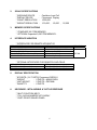
5
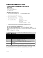
2.
SCALE SPECIFICATIONS
* WEIGHING DEVICE
* DISPLAY DEVICE
* COUNT RESOLUTION
* WEIGHT RESOLUTION
3.
:
:
:
:
Cantilever Load Cell
Fluorescent Display
1/500,000
1/10,000 , 1/5,000 , 1/2,500
MEMORY SPECIFICATIONS
* STANDARD 385 ITEM MEMORY.
* OPTIONAL Expanded 3,080 ITEM MEMORY.
4.
INTERFACE VARIATION
* INTERFACES FOR REMOTE APPARATUS
TYPE OF PORT
RS-232C-1(8PIN) - DIN
RS-232C-2 (8PIN) - DIN
RS-232C-3 (8PIN) - DIN
TTL OUTPUT (8PIN) or RS-422 (8PIN)
KEY BOARD I/F
USES
MODEM/DATA RECORDER
BAR CODE LASER SCANNERS
EXTERNAL PRINTER
SET POINT OUTPUT
KEY BOARD (IBM-AT)
* OPTIONAL INTERFACES FOR REMOTE LOAD CELLS
TYPE OF PORT
REMOTE LOAD CELL -1 15 Pin Amphenol
REMOTE LOAD CELL -2 15 Pin Amphenol
5.
USES
FOR REMOTE CELL PLATFORM
FOR REMOTE CELL PLATFORM
DISPLAY SPECIFICATION
* 20 DIGITS ( 5 X 7 DOTS) Fluorescent DISPLAY
* WEIGHT
: 5 DIGITS + MINUS SIGN
* UNIT WEIGHT
: 5 DIGITS + DECIMAL
* QUANTITY
: 6 DIGITS
6.
KEYBOARD - WITH AUDIBLE & TACTILE RESPONSE
* MULTI-FUNCTION KEYS
* FULL ALPHA-NUMERIC KEY ARRAY
* DUST PROOF SEALED PANEL
6
REMARKS
STANDARD
OPTION
7.
PRINTER
THERMAL DIRECT PRINT
* 0.135 mm x 0.135 mm SQUARE DOT HEAD
* 66 mm WIDE HEAD = (2.5”)
* 448 DOTS/LINE IN/PER/MIN SPEED
* AUTO ALIGNING LABEL
* LABEL PEEL BAR
* TAKE-UP REEL
* CASSETTE LOADING
* PAPER CUTTER
* LABELS OR PAPER STOCK
8.
ELECTRICAL REQUIREMENT
* OPERATION VOLTAGE
* OPERATING FREQUENCY
* POWER CONSUMPTION
* CABLE LENGTH
9.
STANDARD
:
:
:
:
117
60 Hz
15 W
6 FOOT
OPTIONAL
220, 230, 240 Vac
50 Hz
ENVIRONMENTAL REQUIREMENT
* OPERATING TEMPERATURE :
* OPERATING HUMIDITY
:
0 ~ 40C ( -4F ~ 104F)
15% TO 85% RH
10. DIMENSION
* OVERALL - WIDTH x DEPTH
x HEIGHT
16.14(W) x 16.06 (D) x 6.2 (H) inches
410(W) x 498 (D) x 158 (H) mm
* TOTAL WEIGHT :
11.2kg (24.lb.)
7
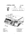
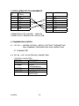
2.
3.
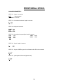
OVERALL VIEW
SIDE VIEW
NAME
OF
EACH
PART
1. MAIN SWITCH
2. SCALE 1
3. SCALE 2
4. DISPLAY WINDOW
5. OPERATION KEYS
6. PRINTER
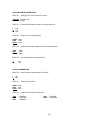
7. CONNECTOR PANEL
A.
B.
C.
D.
E.
F.
G.
8
REMOTE LOAD CELL -1 or 3
REMOTE LOAD CELL-2
PC COMMS / MODEM
SET POINT OUTPUT
SECONDARY RS-232
IBM KEY BOARD
PEN/LASER SCANNER
9
4. DISPLAY and KEYBOARD
INDICATORS
ZERO
STABLE
NET
KG
SCALE 1~3
INSUFF
RECOMP.
MEMORY
IN
OUT
JOB MODULE1~8
(9~16)
MEANINGS
Weight is zero
Weight is stable
Presence of a tare weight
Scale weighing in kg mode.( Default is lb. mode.)
Scale Platform that is in use
Sample size is too small to calculate Unit Weight
Unit weight may be recalculated by pressing PIECES key.
An accumulated total is in memory
Quantities being added to inventory and movement data
Quantities being removed to inventory and movement data
Auto job pattern operation
9~16 will flash when in process of auto job operation.
10
1.3.3 FUNCTION OF KEYS
0
~
9
NUMERIC KEYS
Key numerical values into the system.
•
I N/OUT
DECIMAL POINT
Enter decimal point when entering data
Toggle between in, out, non add operation together with [SHIFT DOWN] key in
operation mode.
CLEAR
CLEAR
Æ
Clear keyed-in data from display.
Delete the data in memory file.
FEED
Feed paper
MODE
MODE
Toggles between FOUR modes. Operation, Program, Check, Maintenance.
Exits modes without saving data.
AUTO / MANUAL
AUTO
MANUAL
LOT
NO.
REZERO
Toggles between Auto Job Operation and Manual Operation in OPR. mode.
Back to the precious screen in programming data.
LOT NUMBER
Enter the key-in data to LOT No. in OPR mode.
RE-ZERO
Eliminates weight from the weight dispaly with no tare and causes it to show a true
zero. Re-Zero “V” shows software version any mode.
TARE
TARE
←
Enter a tare value into the system.
Toggles the data files to program or access
Move the triangle cursor to Left.
11
UNIT WEIGHT
UNIT
WEIGHT
→
Enter weight per 1000 count of pieces or is pressed after enter a weight value.
Toggles the data files to program or access
Move the triangle cursor to Right.
SCALE
SCALE
Toggles between the scales, if the system is with pural scales.
PLUS
+
Weight data addition and print out
In Maintenance mode, advances to the next choice, when the triangle cursor is
blinking.
MINUS
_
Weight data subtraction and print out
In Maintenance mode, moves back to the previous choice, when the triangle
cursour is blinking.
PIECES
Sample entry in counting mode to calculate UNIT WEIGHT. Automatic 10 pieces or
key enter any other sample quantity placed on platter
PIECES
CODE
CODE
Calls ITEM data from memory file.
Reprints the same label without saving inventory total in OPR. Mode. ( SD / code)
Prints TEST LABEL (TOTAL LABEL) in programming FREE FORMAT.
RETRY
ENTER
Print total accumulation in OPR. mode.
Enters set up choices and advances to next choice. Then, at the end of
choices,store the data into memory files.
ENTER
A
+
~
,
−
Z
,
ALPHABET / PLUS / PLUS / MINUS / SLASH
Key alphabetical data into the system.
Assign the data to ITEM FILES together with [SHIFT DOWN] key.
/
NOTE
* "[Y] key is used for executing the deletion in the deletion screen.
* "[N] key is used for escaping the deletion screen.
* "[M] key is used for test printing (gross label) in free format setting.
12
SPACE
lb / kg
SHIFT
DOWN
SPACE
Enters SPACE in alphabetical data entry.
Toggles the display between pound (lb) and kilogram (kg). This function is
available in LB version.
Prints TEST LABEL (ITEM LABEL) in programming FREE FORMAT
SHIFT DOWN + DESIGNATED KEY
Change the key functions to the lower line of Alphabet keys.
1. A = ENTER TEMPORARY PART NUMBER
2. B = ENTER TEMPORARY PART NAME
3. C = SEE SHELF LOCATION
4. D = SEE INVENTORY BALANCE
5. E = SEE THRESHOLD ORDER POINT
6. F = SEE SET POINT QTY & PRECENTAGE
7. G = SEE SCALE PLATFORM
8. H = AUTO JOB PATTERN FOR RECEIVING “IN”
9. I = AUTO JOB PATTERN FOR SHIPPING “OUT”
10. J = AUTO JOB PATTERN FOR NON-ADD
11. K = SEE DAY QTY IN
12. L = SEE DAY QTY OUT
13. M = SWITCH NET / GROSS WEIGHT
[1-10 / SD / N / * ]
14. N = SELECT ADDRESS/ MEMO TO PRINT
15. O = SELECT FORMAT TO PRINT 1-7
[ 1- 7 / SD / O / CLEAR / * ]
16. P = PRINTER TURNED ON or OFF
[ NO INDICATOR LAMP ]
17. Q = BATCH PRINT LABELS TO 999 EACH [ QTY / SD / Q / CLEAR / * ]
18. R = RESET SEQUENCE NUMBER
[ NO / SD / R =CONTINUOUS ]
19. V = VERSION NUMBER
[REZERO V IN ANY MODE , VER.2.00 AND ABOVE]
20. SPACE = TOGGLE “LB / KG “ CONVERT MODE
21. CODE = RETRY - PRINT ADDITIONAL LABEL
= TOGGLE INVENTORY ACTIVITY “IN / OUT / NON-ADD “
22. “ .”
23.
= STOP PRINTING AFTER FIELD COMPLETE
24. LOT NO=PRESS TWICE TO DELETE LOT NUMBER
SHIFT
UP
SHIFT UP
Change the key functions to enter special characters from the upper line on
Alphabet keysheet. Punctuation in any A/N field.
13
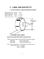
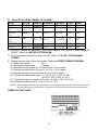
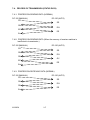
5. LABEL SIZE AND SET UP
6. SPECIFICATION OF LABELS AND RECEIPT PAPER
Outer diameter of rolls
Inner diameter of rolls
Width of receipt rolls
Width of label rolls
Width of label Stock
: 105 mm
: 40 mm
: 66 mm
: 66 mm
: 64 mm
= 4-1/4”
= 1- /8”
= 2-11/16”
= 2-11/16”
= 2-9/16”
width of roll
Outer diameter
105 mm
Inner diameter
40 mm
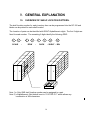
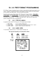
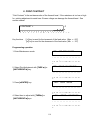
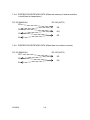
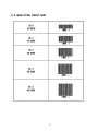
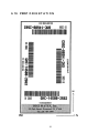
7. STANDARD LABEL FORMAT
DC-150 has 7 standard label formats and 2 free label formats.
Select the label format in PRINT SPEC in maintenance mode.
THREE TYPES OF LABELS CAN BE PRINTED IN OPERATION MODE.
ITEM LABEL
TOTAL LABEL
GROSS LABEL
...... Issued in single operation
...... Issued in multiple operation
...... Issued in gross weight operation
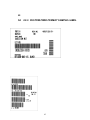
NOTE: Refer to APPENDIX I to see the samples of standard formats.
Label Quantity: 55mm = 500 labels
77mm = 350 labels
120mm = 250 labels
14
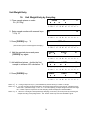
8.
LABEL & PAPER ROLL SET UP
1. Remove front panel of printer.
2. Release thermal head block by pulling down the plastic lock.
3. Open the right side door of printer block by pushing in panel & releasing.
4. Pull out label cassette from the main unit.
5. Twist the roll holder s 45 degree clockwise and pull it out to remove.
6. Take out the empty roll core and replace with a new roll.
7. In case of label, take the end of the label stock and run it above the guides o and through
dispenser p and lock backing paper on take up reel q with paper clampr.
8. Replace by pushing roll holder sinto set reeln as drawing, until it stops.
9. Set label and paper switch on the inside of label cassette.
[LEFT (label) ↔ RIGHT(paper)]
10.Slide cassette into the main unit, align the metal dispenser p shaft under the thermal
head.
11.Close the thermal head block by pushing the top of the plastic lock.
12.Close the side panel and replace the front panel of printer.
13. Align & adjust tension of the label roll by pressing [→
→] (feed) Key
14. In the case of paper, install paper roll the same as label stock
15. Fold the end of the paper and hold the fold on dispenser p .
16. Replace the cassette into the main unit and close the thermal head block the same as
label stock.
17. Align the paper by pressing [→
→] (feed) key
15
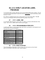
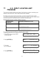
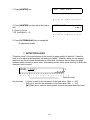
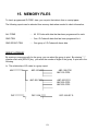
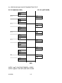
9. GENERAL EXPLANATION
10.
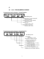
OVERVIEW OF SHELF LOCATION PATTERN.
The shelf location number for each inventory item can be programmed into the DC-150 and
labels can be printed for each shelf location.
The Location of parts can be identified with EIGHT AlphaNumeric digits. The first 2 digits are
fixed for scale number. The remaining 6 digits identify the following GRID:
0
1
-
SCALE
-
1
0
2
ROW
-
0
2
-
RACK
4
-
E
- SHELF - BIN
2
3
d
a
e
4
b
c
f
Note 1)" Only ONE shelf location number can be assigned to a part.
Note 2) "AlphaNumeric Grid default is set to “01-ZZ-ZZ-Z-Z “ which allows any
combination of A/N characters.
16
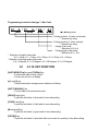
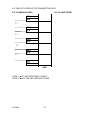
11.
OVERVIEW OF SET POINT OUTPUT
Two target values can be programmed for each ID CODE in Memory. A beep sounds to
indicate when the target value is reached. (SET1/SET2.)
The combination of SET1 and SET2 can be selected as follows in Maintenance mode.
COMBINATION
QUANTITY & PERCENTAGE
QUANTITY & PERCENTAGE ( TO STOP
WEIGHT & PERCENTAGE
UPPER LIMIT & LOWER LIMIT OF WEIGHT
UPPER LIMIT & LOWER LIMIT OF QUANTITY
SET POINT 1
QUANTITY
QUANTITY
WEIGHT(g)
UPPER LIMIT
UPPER LIMIT
SET POINT 2
% OF SET POINT 1
% OF SET POINT 1
% OF SET POINT 1
LOWER LIMIT
LOWER LIMIT
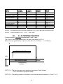
I.E.: COMBINATION = QUANTITY (25,000 PCS.) & 80 %
INTERMITTENT
SET POINT 2
0 - - - - - - - - - - - - - - - - - - - - - - - - - - - - - - 80 %
20,000 PCS
CONTINUOUS
SET POINT 1
25,000 PCS
TOTAL
* When the weight value is a equal to (or over) the target SET1, intermittent buzzer
sounds. When the weight value is a equal to (or over) the target SET2, buzzer change
to continuous.
17
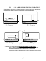
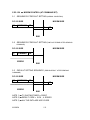
12.
REMOVE THE LOCKING SCREW FOR LOAD CELL
The load cell is locked with socket screw and nut during transportation. Please remove
the locking screw, nut and the metal plate during set up as shown in the following drawing.
1.1. When setting up,
release the load cell
a. Loosen the lock nut.
b. Remove socket screw.
c. Remove 4 screws and
the metal plate.
1.2. Before
transportation,
mount load cell lock.
a. Set metal plate with
4 screws.
b. Set the socket screw
until it touches the
load
cell and tighten up one
revolution.
c. Tighten the lock nut.
NOTE : " When
Shipping DC-150
Be Sure To Lock
Scale As Shown
Or Permanent
Damage May
Occur To Load Cell
That Would
Require
Non-Warranty
Replacement.
NOTE : " When
calibration cannot be performed correctly, please check to see whether all
the screws have been removed.
18
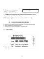
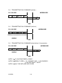
13.
SOFTWARE VERSION RECALL (Ver. 2.00 and above)
Software Version recall may be used on any DC-150 with software version 2.00 and above.
1. Press [MODE] key.
OPERATION MODE
Any Mode may be displayed.
2. Press [REZERO] & [V] key at the same time.
the version number will be displayed for several
seconds then return to whichever mode was
previously displayed.
Ver. D2.00
OPERATION MODE
14.
STOP PRINTING ENTRY
Any time when printing reports or spec list you wish to stop printing
Press and the [→
→] (feed)key in until printing stops then release.
15.
TOGGLE INVENTORY ( IN / OUT / NON-ADD )
TO TOGGLE BETWEEN IN / OUT / NON-ADD
Press [SHIFT DOWN] key followed by the [••] within 3 seconds.
NOTE: "An indicator light will show ‘IN’ AND ‘OUT’. No light will light for ‘NON-ADD’.
19
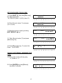
Unit Weight Entry
16.
Unit Weight Entry by Sampling
1. Place sample pieces on scale.
Ex.) 0.015kg
0.0150
∇
∇
0.
∇
0
∇
. . . . . . . . . . . . . . . . . . . .
Z S N K 1
2. Enter sample number with numeric keys.
*1 Ex) 15
2 3 I R M I O 1 2 3 4 5 6 7
(2)
8
15
. . . . . . . . . . . . . . . . . . . .
Z S N K 1
3. Press [PIECES] key. *2
2 3 I R M I O 1 2 3 4 5 6 7
8
---------------- ADD 12 ------------------
(The number of pieces needed appears in display.)
. . . . . . . . . . . . . . . . . . . .
Z S N K 1
4. Add the required pieces and press
[PIECES] key again.
0.0270
∇
2 3 I R M I O 1 2 3 4 5 6 7
0.9970
∇
8
27
∇
. . . . . . . . . . . . . . . . . . . .
Z S N K 1
5. Add additional pieces - double the first
sample to enhance UW calculation. *3
2 3 I R M I O 1 2 3 4 5 6 7
0.0835
∇
0.9970
∇
∇
8
84
∇
. . . . . . . . . . . . . . . . . . . .
Z S N K 1
6. Press [PIECES] key.
0.0835
∇
2 3 I R M I O 1 2 3 4 5 6 7
0.9917
∇
8
84
∇
. . . . . . . . . . . . . . . . . . . .
Z S N K 1
NOTE: *1)
NOTE: *2)
"
"
2 3 I R M I O 1 2 3 4 5 6 7
8
If using a sample of 10 pcs., press PIECES key without entering a number of sample.
To have accurate unit weight calculation, the sample weight must be more than the insufficient range
of the scale. (Insufficient range = 0.0% ~ 0.7 % of scale capacity) If sample weight is less than the range,
the number of pieces required for accurate sampling would be displayed in PROCEDURE 3.
NOTE: *3) " When the unit weight is developed though sampling, the accuracy can be improved by increasing the
sample size using recomputing feature. This function works only when the “RECOMP” sign lit.
20
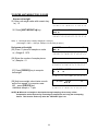
17. Unit Weight Entry by Numeric Keys
1. Stand-by Status
0.0000
∇∇
∇
0.
∇
0
∇
. . . . . . . . . . . . . . . . . . . .
Z S N K 1
2. Enter Unit Weight Value with numeric keys
Ex.) 3.756kg / 1000 pcs.
2 3 I R M I O 1 2 3 4 5 6 7
(5)
8
3.756
. . . . . . . . . . . . . . . . . . . .
Z S N K 1
3. Press [UNIT WEIGHT→
→] key. *1
2 3 I R M I O 1 2 3 4 5 6 7
0.0000
∇∇
∇
3.7560
8
0
∇
. . . . . . . . . . . . . . . . . . . .
Z S N K 1
2 3 I R M I O 1 2 3 4 5 6 7
Note: *1) "The unit weight value should be Unit Weight/1,000.
Note: 2) " To clear unit weight, press [0] and [UNIT WEIGHT] key.
21
8
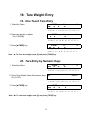
18. Tare Weight Entry
19. One Touch Tare Entry
1. Stand-by Status
0.0000
∇∇
∇
0.
∇
0
∇
. . . . . . . . . . . . . . . . . . . .
Z S N K 1
2. Place tare weight on platter
Ex.) 0.0335kg
2 3 I R M I O 1 2 3 4 5 6 7
0.0335
∇
0.
∇
8
0
∇
. . . . . . . . . . . . . . . . . . . .
Z S N K 1
3. Press [←
←TARE] key.
2 3 I R M I O 1 2 3 4 5 6 7
0.0000
∇∇
8
0.
∇
∇
0
∇
. . . . . . . . . . . . . . . . . . . .
ZS N K 1
2 3 I R M I O 1 2 3 4 5 6 7
8
Note : " To clear tare weight, enter [0] and press [TARE] key.
20. Tare Entry by Numeric Keys
1. Stand-by Status
0.0000
∇∇
∇
0.
∇
0
∇
. . . . . . . . . . . . . . . . . . . .
Z S N K 1
2. Enter Tare Weight Value with numeric keys
Ex.) 0.0275
2 3 I R M I O 1 2 3 4 5 6 7
(6)
8
0.0275
. . . . . . . . . . . . . . . . . . . .
Z S N K 1
3. Press [←
←TARE] key.
2 3 I R M I O 1 2 3 4 5 6 7
-0.0275
∇∇
∇
0.
∇
8
0
∇
. . . . . . . . . . . . . . . . . . . .
Z S N K 1
2 3 I R M I O 1 2 3 4 5 6 7
Note : " To clear tare weight, enter [0] and press [TARE] key.
22
8
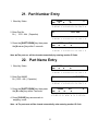
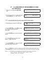
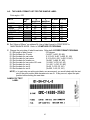
21. Part Number Entry
1. Stand-by Status
0.0000
∇∇
∇
0.
∇
0
∇
. . . . . . . . . . . . . . . . . . . .
Z S N K 1
2. Enter Part No.
Ex.) 1233 - 44k (Capacitor)
2 3 I R M I O 1 2 3 4 5 6 7
(8)
8
1233 - 44k
. . . . . . . . . . . . . . . . . . . .
Z S N K 1
3. Press the [SHIFT DOWN] key then press
the [A PARTNO.] key within 3 seconds.
2 3 I R M I O 1 2 3 4 5 6 7
0.0000
∇∇
∇
0.0
∇
8
0
∇
. . . . . . . . . . . . . . . . . . . .
Z S N K 1
2 3 I R M I O 1 2 3 4 5 6 7
8
Note :" The parts no. will be cleared automatically by entering another ID Code.
22. Part Name Entry
1. Stand-by Status
0.0000
∇∇
∇
0.
∇
0
∇
. . . . . . . . . . . . . . . . . . . .
Z S N K 1
2. Enter Part NAME
Ex.) 1233 - 44k ( Capacitor)
2 3 I R M I O 1 2 3 4 5 6 7
(9)
8
CAPACITOR
. . . . . . . . . . . . . . . . . . . .
Z S N K 1
3. Press the [SHIFT DOWN] key then press
the [B P NAME] key within 3 seconds.
2 3 I R M I O 1 2 3 4 5 6 7
0.0000
∇∇
∇
0.0
∇
8
0
∇
. . . . . . .. . . . . . . . . . . . .
Z
S N K 1 2 3 I R M I
O 1 2 3 4 5 6 7 8
4. Press [CLEAR] key returns scale to
weighing mode
Note : " The part name will be cleared automatically when entering another ID Code.
23
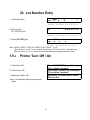
23. Lot Number Entry
1. Stand-by Status
0.0000
∇∇
∇
0.
∇
0
∇
. . . . . . . . . . . . . . . . . . . .
Z S N K 1
2. Enter Lot No.
Ex.) CWN-CO124
2 3 I R M I O 1 2 3 4 5 6 7
(9)
8
C W N- C 0 1 2 4
. . . . . . . . . . . . . . . . . . . .
Z S N K 1
3. Press [LOT NO.] key.
2 3 I R M I O 1 2 3 4 5 6 7
0.0000
∇∇
∇
0.0
∇
8
0
∇
. . . . . . . . . . . . . . . . . . . .
Z S N K 1
2 3 I R M I O 1 2 3 4 5 6 7
8
Note: "MISC. SPECS : SPEC 02 KEEP LOT NO. Select - Y or N
(Spec 02 set to Y or N) Lot no. cleared by pressing LOT NO. key twice, then the Y key.
(Spec 02 set to N) Lot no. will be cleared automatically by entering another ID Code
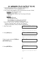
1.9.2
Printer Turn Off / On
1. Turn Printer Off
Press [SHIFT DOWN] key followed by
[P] key within 3 seconds
Press [SHIFT DOWN] key followed by
[P] key within 3 seconds
When main AC power switch turned
OFF then ON
2. Turn Printer ON
3. Automatic Printer ON
Note: "No indicator light to show printer
status.
24
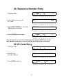
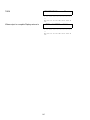
24. Sequence Number Entry
1. Stand-by Status
0.0000
∇∇
∇
0.
∇
0
∇
. . . . . . . . . . . . . . . . . . . .
Z S N K 1
2. Enter Starting Sequence No.
Ex.) 1200
2 3 I R M I O 1 2 3 4 5 6 7
(4)
8
1200
. . . . . . . . . . . . . . . . . . . .
Z S N K 1
3. Press [SHIFT DOWN] key, then press
[R] key within 3 seconds.
2 3 I R M I O 1 2 3 4 5 6 7
SEQ. NO.
8
1200
. . . . . . . . . . . . . . . . . . . .
Z S N K 1
4. Press [CLEAR] key to escape.
2 3 I R M I O 1 2 3 4 5 6 7
0.0000
∇∇
∇
0.0
∇
8
0
∇
. . . . . . . . . . . . . . . . . . . .
Z S N K 1
2 3 I R M I O 1 2 3 4 5 6 7
8
Note ) " Sequence no. increases automatically when pressing ENTER key to print.
Note ) " When sequence no. is set to 0, NO Seq. No. will be printer or increased.
25. ID Code Entry
1. Stand-by Status
0.0000
∇∇
∇
0.
∇
0
∇
. . . . . . . . . . . . . . . . . . . .
Z S N K 1
2. Enter ID code.
Ex) ABC-100#125
2 3 I R M I O 1 2 3 4 5 6 7
(11)
8
ABC-100#125
. . . . . . . . . . . . . . . . . . . .
Z S N K 1
3. Press [CODE RETRY] key.
*
2 3 I R M I O 1 2 3 4 5 6 7
0.0000
∇∇
∇
0.1230
8
0
∇
. . . . . . . . . . . . . . . . . . . .
Z S N K 1
25
2 3 I R M I O 1 2 3 4 5 6 7
8
26. Parts Counting Operation
27. Single Transaction
1. After entering unit weight by any method.
0.0000
∇∇
0.1233
∇
0
∇
. . . . . . . . . . . . . . . . . . . .
Z S N K 1
2. Change task ( IN / OUT / NON-ADD ) by
pressing [SHIFT DOWN] then [••]
key within 3 seconds. *1
2 3 I R M I O 1 2 3 4 5 6 7
0.0000
∇∇
∇
0.1233
8
0
∇
. . . . . . . . . . . . . . . . . . . .
Z S N K 1
3. Place parts on platter.
2 3 I R M I O 1 2 3 4 5 6 7
0.3195
∇
∇
0.1233
8
2590
∇
. . . . . . . . . . . . . . . . . . . .
Z S N K 1
4. Print label by pressing [∗
∗ ENTER] key.
2 3 I R M I O 1 2 3 4 5 6 7
0.3195
∇
∇
0.1233
8
2590
∇
. . . . . . . . . . . . . . . . . . . .
Z S N K 1
2 3 I R M I O 1 2 3 4 5 6 7
8
Note 1: " Quantities received IN or shipped OUT of inventory are recorded for each ID code.
To count an item in the Inventory file, change the task in step 2.
Note 2: " When both IN and OUT lamps are off, the quantities do not affect Inventory level.
Note 3: " To print a label without counting, enter quantity of parts and press ENTER key.
26
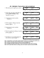
28. Multiple Transaction (Accumulation)
1. After entering unit weight by any method.
0.0000
∇∇
0.1233
∇
0
∇
. . . . . . . . . . . . . . . . . . . .
Z S N K 1
2. Change task ( IN / OUT / NON-ADD ) by
pressing [SHIFT DOWN] then [••]
key within 3 seconds. *1
2 3 I R M I O 1 2 3 4 5 6 7
0.0000
∇∇
∇
0.1233
8
0
∇
. . . . . . . . . . . . . . . . . . . .
Z S N K 1
3. 1st placement of parts on platter.
(Quantity 1)
2 3 I R M I O 1 2 3 4 5 6 7
0.3195
∇
∇
0.1233
8
2590
∇
. . . . . . . . . . . . . . . . . . . .
Z S N K 1
4. Add the quantity to Memory & print by
*2
pressing [+] key.
2 3 I R M I O 1 2 3 4 5 6 7
0.3195
∇
∇
0.1233
8
2590
∇∇
. . . . . . . . . . . . . . . . . . . .
Z S N K 1
5. 2nd placement of parts on platter.
(Quantity 2)
2 3 I R M I O 1 2 3 4 5 6 7
0.0240
∇
∇
0.1233
8
194
∇∇
. . . . . . . . . . . . . . . . . . . .
Z S N K 1
6. Delete the quantity from Memory & print by
pressing [−
−] key. *2
2 3 I R M I O 1 2 3 4 5 6 7
0.0240
∇
∇
0.1233
8
194
∇∇
. . . . . . . . . . . . . . . . . . . .
Z S N K 1
7. Print Balance of accumulated parts and
clear memory by pressing [∗
∗]. *3
2 3 I R M I O 1 2 3 4 5 6 7
0.0240
∇
∇
0.1233
8
2590
∇
. . . . . . . . . . . . . . . . . . . .
Z S N K 1
2 3 I R M I O 1 2 3 4 5 6 7
8
Note 1: " Quantities received IN or shipped OUT of inventory are recorded for each ID code.
Note 2: " Each transaction label will be printed by pressing [+] and [-] keys.
Note 3: " Grand total label will be printed by pressing [ENTER] key.
Note 4: " When both IN and OUT lamps are off, the quantities do not affect Inventory.
Note 5: " To print label without counting, enter the number of parts and press ENTER
27
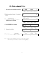
29. Batch Label Print
1. After entering unit weight by any method.
0.0000
∇∇
0.1233
∇
0
∇
. . . . . . . . . . . . . . . . . . . .
Z S N K 1
2. Enter the number of labels to be printed.
Ex) 30
2 3 I R M I O 1 2 3 4 5 6 7
(1)
8
30
. . . . . . . . . . . . . . . . . . . .
Z S N K 1
3. Press [SHIFT DOWN] key then press
[Q] key within 3 seconds.
2 3 I R M I O 1 2 3 4 5 6 7
BATCH PRINT
=
8
30
. . . . . . . . . . . . . . . . . . . .
Z S N K 1
4. Press [CLEAR] key to escape.
2 3 I R M I O 1 2 3 4 5 6 7
0.0000
∇∇
∇
0.1233
8
0
∇
. . . . . . . . . . . . . . . . . . . .
Z S N K 1
5. Place parts on platter.
2 3 I R M I O 1 2 3 4 5 6 7
0.3195
∇
∇
0.1233
8
2590
∇
. . . . . . . . . . . . . . . . . . . .
Z S N K 1
6. Print labels by pressing [∗
∗ ENTER] key. *1
2 3 I R M I O 1 2 3 4 5 6 7
0.3195
∇
∇
0.1233
8
2590
∇
. . . . . . . . . . . . . . . . . . . .
Z S N K 1
2 3 I R M I O 1 2 3 4 5 6 7
Note 1: " The number of labels entered in procedure 2 are printed.
Enter “1” in procedure 2, to return to one label printing.
28
8
1.14 Selecting Label Format
This procedure may be done in operation mode as a temporary change.
Refer to Print Specs no. 33 for permanent setting (standard specs only)
1. Stand-by Status
0.0000
0.
∇∇
∇
∇
0
∇
. . . . . . . . . . . . . . . . . . . .
Z S N K 1
2 3 I R M I O 1 2 3 4 5 6 7
8
2. Enter Format No. by numeric keys.
Ex.) 3 [Standard 1-7]
3
. . . . . . . . . . . . . . . . . . . .
Z S N K 1
2 3 I R M I O 1 2 3 4 5 6 7
8
PRINT FORMAT =
3. Press [SHIFT DOWN] key then press the
[O] key within 3 seconds.
3
. . . . . . . . . . . . . . . . . . . .
ZS N K 1
4. Press [CLEAR] key to activate format
selected
2 3 I R M I O 1 2 3 4 5 6 7
0.0000
∇∇
8
0.
∇
0
∇
. . . . . . . . . . . . . . . . . . . .
ZS N K 1
2 3 I R M I O 1 2 3 4 5 6 7
8
30. .1 Address Data Entry
1. Stand-by Status
0.0000
∇∇
∇
0.
∇
0
∇
. . . . . . . . . . . . . . . . . . . .
Z S N K 1
2 3 I R M I O 1 2 3 4 5 6 7
8
2. Enter Address No. by numeric keys.
Ex.) 6
6
. . . . . . . . . . . . . . . . . . . .
Z S N K 1
3. Press [SHIFT DOWN] key then press the
[N ADDRSS] key within 3 seconds.
2 3 I R M I O 1 2 3 4 5 6 7
0.0000
∇∇
∇
0.
∇
8
0
∇
. . . . . . . . . . . . . . . . . . . .
ZS N K 1
2 3 I R M I O 1 2 3 4 5 6 7
Note 1: " A maximum of 10 files with 5 lines can be stored in Address file. When label
format has allocated address print area the selected address would be printed on that
label.
29
8
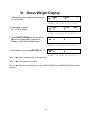
31. Gross Weight Display
1. After entering unit weight and tare weight
by any method.
0.0000
∇∇
0.1233
∇
0
∇
. . . . . . . . . . . . . . . . . . . .
Z S N K 1
4. Place parts on platter.
Ex) 0.3315 weight
2 3 I R M I O 1 2 3 4 5 6 7
0.3315
∇∇
∇
0.1233
8
2690
∇
. . . . . . . . . . . . . . . . . . . .
Z S N K 1
5. Press [SHIFT DOWN] key then press the
[M NET/GROSS] key within 3 seconds to
display or print Gross Weight Mode. *1
2 3 I R M I O 1 2 3 4 5 6 7
8
3.650
∇∇
∇
∇
. . . . . . . . . . . . . . . . . . . .
Z S N K 1
6. Print labels by pressing [∗
∗ ENTER] key. *2
2 3 I R M I O 1 2 3 4 5 6 7
8
3.650
∇∇
∇
∇
. . . . . . . . . . . . . . . . . . . .
Note *1) " Display changes to Gross Weight Mode.
Z S N K 1
2 3 I R M I O 1 2 3 4 5 6 7
8
Note *2) " Gross label will be printed.
Note *3) " To return to counting screen, press [SHIFT DOWN] then [M NET/GROSS] key within 3
seconds.
30
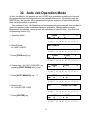
32. Auto Job Operation Mode
In Auto Job Module, the operator can be GUIDED by a systematic prompting for his work
flow pattern that has been selected from the available function list. By pressing only the
[ENTER] key the operator will be advanced through the sequence of operations that has
been set in the pattern of operation.
Five patterns of Auto Job Operation can be programmed and preserved, then recalled to
guide the operator in that established operation procedure. Different patterns can be
programmed for shipping, receiving, non-add operations of each ID code. (See Auto Job
Programming Section 3.6)
1. Stand-by Status
0.0000
∇∇
∇
0.
∇
0
∇
. . . . . . . . . . . . . . . . . . . .
Z S N K 1
2. Enter ID code.
Ex.) ABC-100#125
2 3 I R M I O 1 2 3 4 5 6 7
8
ABC-100#125
. . . . . . . . . . . . . . . . . . . .
Z S N K 1
3. Press [CODE RETRY] key.
*
2 3 I R M I O 1 2 3 4 5 6 7
0.0000
∇∇
0.1230
∇
8
0
∇
. . . . . . . . . . . . . . . . . . . .
Z S N K 1
4. Change task ( IN / OUT / NON-ADD ) by
pressing [SHIFT DOWN] then [•] key
2 3 I R M I O 1 2 3 4 5 6 7
0.0000
∇∇
∇
0.1230
8
0
∇
. . . . . . . . . . . . . . . . . . . .
Z S N K 1
5. Press [AUTO/ MANUAL] key. *1
2 3 I R M I O 1 2 3 4 5 6 7
0.0000
∇∇
∇
0.1230
∇
8
0
∇
. . . . . . . . . . . . . . . . . . . .
Z S N K 1
6. Enter Lot No.
Ex.) CAPACITOR 118E5
2 3 I R M I O 1 2 3 4 5 6 7
(15)
8
CAPACITOR 118E5
. . . . . . . . . . . . . . . . . . . .
Z S N K 1
7. Press [∗
∗ ENTER] key.
2 3 I R M I O 1 2 3 4 5 6 7
0.0000
∇∇
∇
0.1230
∇
8
0
∇
. . . . . . . . . . . . . . . . . . . .
Z S N K 1
31
2 3 I R M I O 1 2 3 4 5 6 7
8
1.16 Auto Job Operation Mode (continued)
8. Place parts on platter.
*
0.0240
∇
0.1230
∇
193
∇
. . . . . . . . . . . . . . . . . . . .
Z S N K 1
9. Press [∗
∗ ENTER] key.
*
2 3 I R M I O 1 2 3 4 5 6 7
0.0240
∇
0.1230
∇
8
193
∇
. . . . . . . . . . . . . . . . . . . .
Z S N K 1
10. Press [∗
∗ ENTER] key to print.
*
2 3 I R M I O 1 2 3 4 5 6 7
0.0240
∇
0.1230
∇
8
193
∇
. . . . . . . . . . . . . . . . . . . .
Z S N K 1
11. Press [∗
∗ ENTER] key.
*
2 3 I R M I O 1 2 3 4 5 6 7
0.0240
∇
∇
0.1230
8
193
∇
. . . . . . . . . . . . . . . . . . . .
Z S N K 1
2 3 I R M I O 1 2 3 4 5 6 7
8
I.e. " The programmed procedure; Lot No. Entry → Counting → Print Label → Operation End.
Alternative Spec setting [ MISC SPECS: spec 13 =y; Omit steps 2 & 3, follow scale prompts.
32
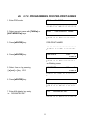
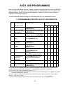
2. PROGRAM MODE
How To Enter The Data Into Memory.
2.1.
HOW TO ENTER PROGRAM MODE
2.2.
KEY OPERATION IN PROGRAM MODE
2.3.
I.D. CODE PROGRAMMING
2.4
DATE & TIME PROGRAMMING
2.5
SET POINT PROGRAM
2.6
FIELD TITLES PROGRAMMING
2.7
PRE-PRINTING PROGRAMMING
2.8
COPY FORMAT PROGRAMMING
2.9
FREE FORMAT PROGRAMMING
2.10 SHELF LOCATION LABEL PROGRAMMING
2.11 SHELF LOCATION RANGE PROGRAMMING
2.12 ADDRESS LABEL PROGRAMMING
progmode.doc 10/15/98
33
SELECTION 2
PROGRAM MODE TABLE OF CONTENTS
2.1
HOW TO ENTER PROGRAM MODE
2.2
KEY FUNCTION IN PROGRAM MODE
2.3
ID PROGRAMMING
2.3.1. ID CODE DATA STORAGE IN MEMORY
2.3.2. PROGRAMMING ID CODE ITEM DATA
2.3.3. DELETION OF PROGRAMMED ID CODE AND ITEM DATA
2.4
2.5
2.6
DATE AND TIME PROGRAMMING
SETPOINT OUTPUT PROGRAMMING
FIELD TITLES PROGRAMMING
2.6.1. LABEL GRID
2.6.2. PROGRAMMING FIELD TITLES
2.6.3. DELETION OF PROGRAMMED FIELD TITLES
PAGE
33
34
35
36
37-43
44
45
46
47
48
49
50
2.7
PRE - PRINT PROGRAMMING OF VENDOR NAME
51
2.7.1.
2.7.2.
2.7.3.
2.7.4.
2.7.4.1.
2.7.4.2.
2.7.4.3.
2.7.4.4.
PRE-PRINTED PROGRAM FIELD
PROGRAMMING FOR PRE - PRINT NAMES
DELETION OF PRE - PRINTCONTENTS
PRINT POSITION AND CHAR. SIZE OF PRE-PRINT NAME
PRINT POSITION
CHARACTER SIZE AND MAGNIFICATION
DISPLAY AND PROGRAMMING SCREEN
PROGRAMMING FOR PRE - PRINT COORDINATE
51
52-53
54
55
55
55
56
56-57
2.8
2.9
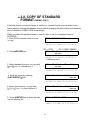
COPY OF STANDARD FORMAT (FORMAT - COPY)
FREE FORMAT PROGRAMMING
58
59
TYPE OF LABELS
LABEL SIZE
CUSTOM FREE FORMAT SAMPLE LABEL
PROGRAMMING DATA FOR EACH LABEL
PRINTING POSITION
LABEL ANGLE AND BAR-CODE ANGLE
DATA TYPE
LABEL FORMAT GRID LAYOUT CHART
PROGRAMMING SCREEN
KEY FUNCTION
PROGRAMMING OPERATION
PROGRAMMING PROCEDURE (USING COPY FUNCTION)
59
59
60-61
62
63
64
65
66-67
68-69
69
70-74
75-76
2.9.1
2.92.
2.9.3.
2.9.4.
2.9.5.
2.9.6.
2.9.7.
2.9.8.
2.9.9.
2.9.10.
2.9.11.
2.9.13.
2.10
2.10.1.
2.10.2.
2.10.3.
2.10.4.
2.10.5.
2.10.6.
2.10.7.
2.10.8.
2.10.9.
2.11
2.12
SHELF LOCATION LABEL PROGRAM
77
LABEL SIZE
PROGRAMMABLE ITEM DATA
PRINT POSITION
LABELANGLE AND BAR-CODE ANGLE
CHARACTER SIZE AND MANIFICATIONS
DATA TYPE
PROGRAMMING SCREEN
PROGRAMMING PROCEDURE
PROGRAM PROCEDURE
77
77
77
78
78
78
78-79
79
818
SHELF LOCATION LIMIT PROGRAM
ADDRESS CONTENTS PROGAM
82
82-83
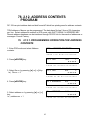
2.12.1. PROGRAMMING OPERATION FOR ADDRESS CONTENTS
2.12.2. DC-150 ADDRESS DATA BASE
2.12.3. DELETION OF PROGRAMMED DATA
34
82-83
83-84
84
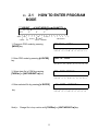
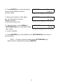
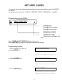
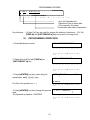
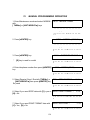
2.1 HOW TO ENTER PROGRAM
MODE
33.
WEIGHT
UNIT WEIGHT
0 . 0 0
QUANTITY
0 .
0
∇∇
∇
∇
∇
• • • • • • • • • • • • • • • • • • • •
ZERO
NET
STABLE
1
2
3
REIN OUT 1
(SCALE)
COMP
KG
INSUFF MEMORY
1. Change to PRG mode by pressing
[MODE] key.
2
3
4 5 6
7
JOB MODULE
PROGRAM
8
MODE
. . . . . . . . . . . . . . . . . . . .
Z S N K 1 2 3 I R M I O 1 2 3 4 5 6 7 8
2. Enter PRG mode by pressing [∗
∗/ ENTER]
key.
PRG: ID CODE
. . . . . . . . . . . . . . . . . . . .
Z S N K 1 2 3 I R M I O 1 2 3 4 5 6 7 8
3. Select data file in PGM by pressing
[TARE/←
←] or [UNIT WEIGHT/→
→] key.
PRG: FREE FORMAT
. . . . . . . . . . . . . . . . . . . .
Z S N K 1 2 3 I R M I O 1 2 3 4 5 6 7 8
4. Enter selected file by pressing [∗
∗/ ENTER]
key.
F.F= FREE
FORMAT 1
. . . . . . . . . . . . . . . . . . . .
Z S N K 1 2 3 I R M I O 1 2 3 4 5 6 78
Note)" Change file in loop routine with [TARE/←] or [UNIT WEIGHT/→] key.
35
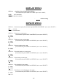
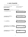
2.2 KEY FUNCTION IN
PROGRAM MODE
34.
[MODE] Key :
To return to the initial screen of each mode without saving programed data.
[AUTO/MANUAL] Key :
To return to the previous screen in programming.
[∗
∗/ENTER] Key :
To enter the next screen in each file.
To enter the programmed data into memory file.
[CLEAR] Key :
To clear mis-set data.
To enter the deletion screen of programmed data.
(LEFT) [TARE/←
←] and (RIGHT) [UNIT WEIGHT /→
→] Key :
To select the headings in loop routines.
To move the cursor to left/right when there are plural cursors in a display.
[+] and [−] Key :
To select the data, when cursor of triangle indicator is blinking.
CURSORS
In Programming mode there are two kinds of cursors used:
1.) Lighted cursor ..... The data above lighted cursor should be programmed
by the key entry.
2.) Blinking cursor .... The data above blinking cursor should be selected from
a list of choices.
The selection is to be made by pressing plus or minus keys.
36
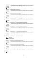
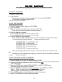
35.
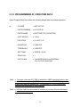
2.3
ID CODE PROGRAMMING
All the following programmable Data Items are linked to ID CODE.
1. ID CODE
--- Max. 16 digit Alpha-Numeric data.
2. UNIT WEIGHT --- Max. 5 digit Numeric data and decimal point.
Unit weight can be entered by using sample counting or direct key
entry when unit weight is known. PRESS [UNIT WEIGHT/→
→] key.
3. TARE WEIGHT --- Max. 5 digit Numeric data and decimal point. Tare weight can
entered by one touch tare entry or direct key entry when tare
PRESS [TARE/←
←] key.
weight is known.
4. PART NO.
--- Max. 32 digit Alpha-Numeric data. Enter Part number
PRESS [SHIFT ↓ ] key, then [A/ PART NO. ] key.
5. PART NAME
--- Max. 32 digit Alpha-Numeric data. Part name can be changed
in operation mode temporarily, then printed in OPN Mode
without changing memory file.
PRESS [SHIFT ↓ ] key, then [B /PART NAME ] key.
6. LOCATION
--- Max. 8 digit Alpha-Numeric data defined by limits.
PRESS [SHIFT ↓ ] key, then [C /LOCATION ] key.
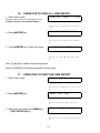
7. INVENTORY
--- Max. 8 digit Numeric data and minus. After you enter the
initial quantity of stock, it is adjusted with receiving IN or
shipping OUT transactions.
PRESS [SHIFT ↓ ] key, then [D/INVENTORY ] key.
8 THRESHOLD
--- Max. 8 digit Numeric data. Threshold is minimum quantity
maintained and point when reordered for stock.
PRESS [SHIFT ↓ ] key, then [E /THRESHOLD]key.
9. SET POINT
--- According to SPEC setting in maintenance mode.
(Quantity = 7 digit, percentage = 2 digit + decimal)
10. SCALE
--- 1 digit 1~3. Select the scale platform that can accommodate
the parts to be counted, 1 - 2 - 3.
PRESS [SHIFT ↓ ] key, then [G /SCALE]key.
11. In /Out / Non-add ---1 digit 1~5. Auto Job Pattern number can be selected for
receiving/shipping/ checking operation for each ID CODE
independently.
37
ID CODE - DATA STORAGE IN
36. 2.3.1
MEMORY
ID Code allows you to store information in memory through program mode. The following information may
be programmed in each ID Code data storage address. The field length will vary with each line of data
from one digit to 32 digits.
Inventory Data Storage Fields
Field Length
1. ID Code
2. Part Number
3. Part Name
4. Unit Weight
5. Stock Location
6 Inventory Balance
7. Threshold Reorder Point
8. Tare Weight
9. Set Point Quantity/Wgt .
10. Scale to Use.
1
2
0
1
3
4
5
6
7
8
Z
Z
9
10
11
12
13
14
15
16
32
NOTE: Fill in blank spaces with data. From 1 to 32 digits. When entering multiple data items, use IBM
AT keyboard, or duplicate this chart before manually entering data into memory for each Code Number.
TASK
PROCEDURE
Program Item Data
PRG: ID CODE
1. Enter A/N ID Code
Press Mode Key to Program, Press ENTER key
Press ENTER ID = Enter ID Code
Press A/N Keys to enter the specific ID Code, Press CODE Key
*"1
All other lines of data can be entered at random, To Exit, Press ENTER Key
A/N Keys, SHIFT DN, then PART NO. (A) key
*"2
A/N Keys, SHIFT DN, then PART NAME (B) key
*"2
Sample New UW or Keyboard enter known UW, Press U/ W key
Enter all eight digits, Press SHIFT DN then LOCATION (C) key
*"2
Enter Starting Quantity, Press SHIFT DN then INVENT (D) key
Enter Re-Order point Quantity, Press SHIFT DN then Th’Hold (E) key
*"2
Enter known tare weight from keyboard, Press TARE key or Place tare weight
on scale, then Press TARE key. Tare weight must be less than scale capacity.
Press SHIFT DN, SETPOINT (F) key, then Enter Quantity, Press SETPOINT
(F) key, Press RIGHT-> key, then Enter %, Press SETPOINT (F) key twice.
To view data Press SHIFT DN, SETPOINT (F) again.
Enter Scale Number 1,2, or 3 , then Press SHIFT DN SCALE (G) key,
2. Enter Part Number
3
4.
5.
6.
7.
8.
Enter Part Name
Enter Unit Weight
Enter Location
Enter Inventory Balance
Enter Threshold
Enter Tare Weight
9. Enter Set Point
10.Select Scale
NOTE *"1) Always enter ID Code FIRST: i.e. Enter “ABC-123” Up to 16 A/N characters in Length.
*"2) Recall entry, Press SHIFT DN then item data key,
Press CLEAR to Delete, respond with ( Y = Yes or N = No )
*"3) AUTO/Manual Key Undo last action.
38
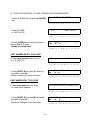
2.3.2 PROGRAMMING ID CODE ITEM DATA
Select Program Mode then enter the following sample data for practice operation.
Ie:
ID CODE
= ABC-100 125
PARTS NUMBER
= H1-1357E-01
PARTS NAME
= ELECTROLYTIC CAPACITOR
UNIT WEIGHT
= 1.5 lbs
LOCATION
= 01-15-07-1-E
INVENTORY
= 5,000 PCS
THRESHOLD
= 3,000 PCS
SET POINT
= 300PCS / 80.0%
SCALE NO.
=1
AUTO JOB #
= 1 for RECEIVING/ 2 for SHIPPING/
3 for CYCLE COUNTING
Note: " You must first enter ID CODE to establish a NEW item data location, then
enter fields of data, press [ENTER] key as last step of ID CODE programming
to save item data into memory file. 385 standard ID CODE locations are
available with expansion to 3080 locations.
Note: " All other fields can be entered at random or omit any of these data items,
if they are not necessary.
39
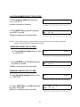
Ie: PRACTICE ENTERING ID CODE ITEM DATA IN PROGRAM MODE.
1. Select ID CODE file and press [∗
∗/ ENTER]
key.
ID=
ENTER
ID CODE
. . . . . . . . . . . . . . . . . . . .
Z S N K 1 2 3 I R M I O 1 2 3 4 5
2. Enter ID CODE.
i.e.) ABC-100125
ID=
6 7 8
ABC-100125
. . . . . . . . . . . . . . . . . . . .
Z S N K 1 2 3 I R M I O 1 2 3 4 5 6 7 8
3. Press [CODE] key to enter the screen to
set the data for ID code.
(Ready for setting data)
*
0.00
∇∇
∇
0.
0
∇
. . . . . . . . . . . . . . . . . . . .
Z S N K 1 2 3
I R M I O 1 2 3 4 5 6 7 8
PART NUMBER ENTRY TO ID CODE
(13)
4. Enter parts number with key entry.
i.e.) H1-1357E-01
H1-1357-E-01
. . . . .. . . . . . . . . . . . . . . .
Z S N K1 2 3 I R I M I O 1 2 3 4 5 6 7 8
5. Press [SHIFT ↓ ] key then [A / PART NO.]
key within 3 seconds.
(Ready for setting the other item data)
*
0.00
∇∇
∇
0.
0
∇
. . . . .. . . . . . . . . . . . . . . .
Z S N K 1 2 3 I R I M I O 1 2 3 4 5 6 78
PART NAME ENTRY TO ID CODE
(2 3) ELECTROLYTIC CAPACITOR
6. Enter parts name with key entry.
i.e.) Electrolytic capacitor
. . . . .. . . . . . . . . . . . . . . .
Z S N K 1 2 3 I R I M IO 1 2 3 4 5 6 7 8
*
7. Press [SHIFT ↓ ] key then [B /PART NAME]
key within 3 seconds.
(Ready for setting the other item data)
∇∇
0.00
∇
0.
0
∇
. . . . .. . . . . . . . . . . . . . . .
Z S N K 1 2 3 I R I M I O 1 2 3 4 5 6 7 8
40
LOCATION NUMBER ENTRY FOR ID CODE
(8)
8. Enter location number with key entry.
i.e.) 01-15-07-1-E
0115071E
. . . . .. . . . . . . . . . . . . . . .
NO DASHES - AUTOMATICALLY INSERTED
Z S NK 1 2 3 I R I M I O 1 2 3 4 5 6 7 8
9. Press [SHIFT ↓ ] key then [C /LOCATION]
key within 3 seconds.
(Ready for setting the other item data)
*
0.00
∇∇
∇
0.
0
∇
. . . . .. . . . . . . . . . . . . . . .
Z S NK 1 2 3 I R
I M IO 1 2 3 4 5 6 7 8
NOTE) *" If you cannot assign a location number, the entry may be out of the range of shelf limits .
Refer to “program the limit of shelf location number.”
INVENTORY ENTRY FOR ID CODE
10. Enter inventory quantity with key entry.
i.e.) 5000 PCS.
(4)
5000
. . . . .. . . . . . . . . . . . . . . .
Z S N K 1 2 3 I R I M I O 1 2 3 4 5 6 7 8
11. Press [SHIFT↓
↓ ] key then [D /INVENTORY]
key within 3 seconds.
(Ready for setting the other item data)
*
∇∇
0.00
∇
0.
0
∇
.. . . .. . . . . . . . . . . . . . . .
Z S N K 1 2 3 I R I M I O 1 2 3 4 5 6 7 8
THRESHOLD ENTRY FOR ID CODE
12. Enter threshold quantity with key entry.
i.e.) 3000 PCS.
(4)
3000
. . . . .. . . . . . . . . . . . . . . .
Z S N K 1 2 3 I R I M I O 1 2 3 4 5 6 7 8
13. Press [SHIFT↓
↓] key then [E/ THRESHOLD]
key within 3 seconds.
(Ready for setting the other item data)
41
*
∇∇
0.00
∇
0.
0
∇
. . . . .. . . . . . . . . . . . . . . .
Z S N K 1 2 3 I R I M I O 1 2 3 4 5 6 7 8
SET POINTS ENTRY FOR ID CODE
14. Press [SHIFT ↓ ] key then [F/SET POINT]
key within 3 seconds.
i.e.) 300PCS (Value *1)/ 80% (Value *2)
S.P=
0/
0
∇∇ ∇ ∇ ∇ ∇ ∇
. . . . .. . . . . . . . . . . . . . . .
Z S NK 1 2 3 I R I M I O 1 2 3 4 5 6 7 8
15. Enter Set point value (*1) and press
[F/set point] key.
S.P=
300/
0
∇∇∇∇∇∇∇∇
. . . . .. . . . . . . . . . . . . . . .
Z S N K 1 2 3 I R I M I O 1 2 3 4 5 6 7 8
16. Move the cursor to right by pressing
[UNIT WEIGHT/ →] key.
S.P=
3 0 0/
0
∇ ∇ ∇∇ ∇∇∇ ∇
. . . . .. . . . . . . . . . . . . . . .
Z S NK 1 2 3 I R I M I O 1 2 3 4 5 6 7 8
17. Enter Set point value (*2) and press
[F/SET POINT] key
S.P=
3 0 0/
8 0 .0
∇ ∇ ∇∇ ∇∇∇ ∇
. . . . .. . . . . . . . . . . . . . . .
Z S NK 1 2 3 I R I M I O 1 2 3 4 5 6 7 8
*
18. Press [F/SET POINT] key. To lock-in Set
Points for ID CODE
0.00
∇∇
∇
0.
0
∇
. . . . .. . . . . . . . . . . . . . . .
Z S N K 1 2 3 I R I M I O 1 2 3 4 5 6 7 8
SCALE PLATFORM NO. ASSIGNED TO ID
CODE
19. Enter scale number with key entry.
i.e.) Scale no. = 1
(1)
1
. . . . .. . . . . . . . . . . . . . . .
Z S N K 1 2 3 I R I M I O 1 2 3 4 5 6 7 8
*
20. Press [SHIFT↓
↓] key then [G/SCALE]
key within 3 seconds.
0.00
∇∇
0.
∇
0
∇
. . . . .. . . . . . . . . . . . . . . .
Z S N K1 2 3 I R I M I O 1 2 3 4 5 6 7 8
42
IN / OUT / NON-ADD ENTRY TO ID CODE
21. Enter Auto job pattern number.
i.e.) Auto job number in. ( 1 )
receiving operation
1
. . . . .. . . . . . . . . . . . . . . .
Z S NK 1 2 3 I R I M I O 1 2 3 4 5 6 7 8
22. Press [ SHIFT ↓] key then [H / IN]
key within 3 seconds.
(Ready for setting the other item data)
*
0.00
∇∇
∇
0.
0
∇
. . . . .. . . . . . . . . . . . . . . .
Z S N K 1 2 3 I R I M I O 1 2 3 4 5 6 7 8
NOTE) * " Auto job no. can be selected from 5 patterns which are programmed in Maintenance mode.
* " You can select Auto Job no. for shipping to check operations with the same pattern as the
above except using [ I/ OUT] or [ J /NON-ADD] key instead of [ H/IN ] key.
* " If auto job number is not assigned for ID code, auto jobs are according to address 4,5,6 of
“MISC SPEC.”
TO ENTER TARE VALUE TO ID CODE TWO
WAYS
Un-known tare weight
23. Place tare weight on the platter
(i.e. 0.500)
*
0.5
∇
0.
0
∇
. . . . .. . . . . . . . . . . . . . . .
Z S N K1 2 3 I R I M I O 1 2 3 4 5 6 7 8
24. Press [TARE/←
← ] key.
*
0.00
∇∇
OR
∇
0.
0
∇
. . . . .. . . . . . . . . . . . . . . .
Z S N K1 2 3 I R I M I O 1 2 3 4 5 6 7 8
Known tare weight
(23) Enter tare weight value with numeric key.
(i.e. 0.50)
(3)
0.50
. . . . .. . . . . . . . . . . . . . . .
Z S
-
(24) Press [TARE /←
← ] key.
∇∇∇
N K 1 2 3 I R I M I O 1 2 3 4 5 6 7 8
0.50
0.0
0
∇
. . . . .. . . . . . . . . . . . . . . .
Z S T K1 2 3 I R I M I O 1 2 3 4 5 6 7 8
.
Note) " To clear tare weight, press [0] and [TARE ] key.
43
TO ENTER UNIT WEIGHT FOR ID CODE
Known unit weight
25. Enter unit weight value with numeric key.
I.e.) 1.5
(3)
1.5
. . . . . . . . . . . . . . . . . . . .
Z S N K 1 2 3 I R M I O 1 2 3 4 5 6 7 8
26. Press [UNIT WEIGHT→
→] key.
-
0.5
∇∇∇
∇
1.5
0
. . . . .. . . . . . . . . . . . . . . .
Z S NK 1 2 3 I R I M I O 1 2 3 4 5 6 7 8
Note) " Unit weight entry is always weight per 1,000 pcs.
(Unit weight 1.5 lbs = 1.5 lbs per 1000pcs or 0.0015 lbs per piece.)
* 0.1575
Un-known unit weight
(25) Place 11 pieces of sample on scale.
i.e.) Weight 0. 1575
∇ ∇
0.
0
∇
. . . . . . . . . . . . . . . . . . . .
Z S N K1 2 3 I R M I O 1 2 3 4 5 6 7 8
(26) Enter the number of sample pieces.
i.e.) Sample =11
(2)
11
. . . . . . . . . . . . . . . . . . . .
Z S NK 1 2 3 I R M I O 1 2 3 4 5 6 7 8
*
(27) Press [PIECES] key to compute
unit weight.
∇
0.1575
∇
14.320
11
∇
. . . . . . . . . . . . . . . . . . . .
Z S N K 1 2 3 I R I MO 1 2 3 4 5 6 7 8
(28) Add more weight, about twice a much
as the first sample to compute a new
UW , press [PIECES] key.
Additional sample = 11 pcs
*
0.3150
14.306
∇ ∇
22
∇
. . . . . . . . . . . . . . . . . . . .
Z S N K 1 2 3
I R M I O 1 2 3 4 5 6 7 8
NOTE) " When the unit weight is developed thorough sampling, the accuracy of that
Computation can be improved by increasing the sample size and using the recomputing
feature. This function works only when the “RECOMP” light is on
44
NOTE 1)
" If the sample quantity is 10 pcs for computing unit weight, press the [PIECES] key
without the necessity of entering the digits “1 & 0” characters as in the first sample.
NOTE 2)
" To clear unit weight value, enter [ 0 ] and press [ UNIT WEIGHHT ] key.
NOTE 3)
" To have accurate unit weight calculation, the sample weight must be more than the
insufficient range of the scale. (Insufficient range is 0.0% ~ 0.7 % of scale capacity)
The factory default is set at 0.1%
NOTE 4)
" If sample weight is less than 0.1%, the display shows the following massage. In this
example case, the sample weight is insufficient to calculate a reliable unit weight.
Place the additional sample pieces on the scale, for accurate sample and
press [PIECES ] key again.
- - - ADD
.
XX
...................
Z S T K 1 2 3 I R I M O 1 2 3 4 5 6 7 8
After you set all the item data in ID code file, press [ENTER] key
to save the data into MEMORY FILE.
The display goes back to the initial screen of “ID=ENTER ID CODE”.
45
37. 2.3.3 DELETION OF PROGRAMMED ID CODE
and ITEM DATA
ID=
1. Select ID code and press [∗
∗ ENTER]
key.
ENTER
ID CODE
. . . . . . . . . . . . . . . . . . . .
Z S N K 1 2
2. Enter ID code which is in memory file and
press [CODE] key. i.e.) ABC-100125
3 I R M I O 1 2 3 4 5 6 7 8
DEL
ABC-100125
. . . . . . . . . . . . . . . . . . . .
Z S N K 1 2 3 I R M I O 1 2 3 4 5 6 7 8
NOTE)
" If the entered ID code exists in memory files, the choice to delete all data or
not must be made by pressing [Y] key to delete entire file or [N] key to advance.
- 0.50
3. Press [ N ] key to enter ID CODE fields.
87.100
∇∇∇
0
∇
. . . . . . . . . . . . . . . . . . . .
ZS
N K 1 2 3 I R M I O 1 2 3 4 5 6 7 8
P.NA=E L E C T R O L I T I C C A P
4. Press [ SHIFT↓
↓] key, then [B/PART NAME]
key to recall programmed data of
parts name.
. . . . . . . . . . . . . . . . . . . .
Z S N K 1 2 3 I R M I O 1 2 3 4 5 6 7 8
5. Press [CLEAR] key to enter the deletion
screen.
DEL ITEM-NO. H 1 - 1357E-01
. . . . . . . . . . . . . . . . . . . .
Z S N K 1 2 3 I R M I O 1 2 3 4 5 6 7 8
6. To delete programmed data, press
[Y] key, or [N] to keep data.
- 0.50
∇∇∇
87.100
0
∇
. . . . . . . . . . . . . . . . . . . .
Z S N K 1 2 3 I R M I O 1 2 3 4 5 6 7 8
7. Press [∗
∗ ENTER] key to select ID CODE,
then revise data in memory file.
ID = ENTER ID CODE
. . . . . . . . . . . . . . . . . . . .
Z S N K 1 2 3 I R M I O 1 2 3 4 5 6 7 8
Note 1) " [TARE←] key is used for scrolling UP the display of the programmed data to the left edge
[UNIT WEIGHT→] key is used for scrolling DOWN the display of the programmed data to the right edge.
Note 2)
" You can delete any of the following item data with the same operation as the above
(Part no. , Part name , Shelf location number , Inventory , Set point ,
Threshold , Scale no., and Auto job no.)
46
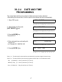
38. 2.4 DATE AND TIME
PROGRAMMING
The current date and time are printed on labels and reports when selected.
After setting the current time, a built-in quartz clock renews the times automatically.
1. Enter PRG mode.
PRG: ID CODE
. . . . . . . . . . . . . . . . . . . .
Z S N K 1 2 3 I R M I O 1 2
2. Select Date and Time with
[UNIT WEIGHT →] key.
3 4 5 6 7 8
PRG: DATE / TIME
. . . . . . . . . . . . . . . . . . . .
Z S N K 1 2
3 I R M I O 1 2 3 4 5
6 7 8
D/T = 06 - 0 1 - 9 4 / 1 3 : 4 5
3. Press [∗
∗ ENTER] key.
Previous D & T
. . . . . . . . . . . . . . . . . . . .
Z S N K 1 2 3
4. Enter date and time continually with
numeric key.
i.e.) February 20, 1995 PM 3:00
D/T
I R M I O 1 2 3 4 5 6 7 8
0220951500
. . . . . . . . . . . . . . . . . . . .
Z S N K 1 2
PRG:
5. Press [∗
∗ ENTER ] key.
3 I R M I O 1 2 3 4 5 6 7
DATE / TIME
. . . . . . . . . . . . . . . . . . . .
Z S N K 1 2 3 I R M I O 1 2 3 4 5 6 7 8
Note 1) " The data entry for date and time are made with 10 continuous digits of numeric entry.
Note 2) " The data format can be chosen by 3 patterns in Misc Spec 12 in maintenance mode.
Day
(2) / Month(2) / Year (2) and Hour (2) / Time (2)
Month (2) / Day
(2) / Year (2) and Hour (2) / Time (2)
Year (2) / Month (2) / Day (2) and Hour (2) / Time (2)
47
8
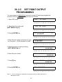
39. 2.5 SET POINT OUTPUT
PROGRAMMING
You can program an INDIVIDUAL set point for each ID Code being weighed and
counted or set the GENERAL set point value for all items.
1. Enter PRG mode
PRG:
ID CODE
. . . . . . . . . . . . . . . . . . . .
Z S N K 1 2
2. Select Set Point value with
[UNIT WEIGHT →] key.
3 I R M IO1
2 3 4 5
6 7 8
PRG: SET POINT
. . . . . . . . . . . . . . . . . . . .
Z S N K 1 2
3 I R M I O 1 2 3 4 5
S.P=
3. Press [∗
∗ ENTER] key.
0/
6 7 8
0
∇ ∇∇ ∇∇∇ ∇
. . . . .. . . . . . . . . . . . . . . .
Z S N K 1 2 3 I R I M I O 1 2 3 4 5 6 78
4. Enter Set point value 1 and press [ F ] key.
I.e.) Set point 1 = 5,000 Set point 2=3,000
S.P=
5 0 0/
0
∇ ∇∇ ∇∇∇ ∇∇
. . . . .. . . . . . . . . . . . . . . .
Z S N K 1 2 3 I R I M I O 1 2 3 4 5 6 7 8
5. Move the cursor to right by pressing
[UNIT WEIGHT→
→] key.
S.P=
5 0 0 0/
0
∇ ∇ ∇∇ ∇∇∇ ∇
. . . . .. . . . . . . . . . . . . . . .
Z S NK 1 2 3 I R I M I O 1 2 3 4 5 6 7 8
6. Enter Set point value 2.
S.P=
5 0 0 0/
3000
∇ ∇∇ ∇∇ ∇ ∇
. . . . .. . . . . . . . . . . . . . . .
Z S
N K1 2 3 I R I M I O 1 2 3 4 5 6 78
S.P=
7. Press [F] key.
5 0 0 0/
3000
∇ ∇∇ ∇∇ ∇ ∇
. . . . .. . . . . . . . . . . . . . . .
Z S N K 1 2 3 I R I M I O 1 2 3 4 5 6 7 8
PRG: SET POINT
8. Press [∗
∗ ENTER] key.
. . . . . . . . . . . . . . . . . . . .
Z S N K 1 2 3 I R M I O 1 2 3 4 5
Note) " You can change the combination of set points functions in Misc Spec 00-01 in
Maintenance mode.
48
6 7 8
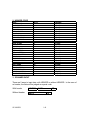
40.
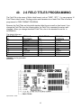
2.6 FIELD TITLES PROGRAMMING
The Field Title is the name of field in label format, such as “TARE”, “QTY”. You can program 16
Field Titles in label format. Printing position and character size of each Field Title in format is
programmed in FREE FORMAT PROGRAM.
Because the Field Titles are linked with standard label format as well as free format, if you
change the Field Title from the following table, the Field Title in standard format are also
changed. When you change the default Field Title, refer to the standard format list in
APPENDEX I.
The default titles are:
FIELD TITLES
NO.
T1
T2
T3
T4
T5
T6
T7
T8
Contexts
DEFAULT
CONTENTS
GROSS
NET
TARE
P.NAME
P.NO.
ID CODE
LOT NO.
QTY
FIELD TITLES
NO.
T9
T 10
T 11
T 12
T 13
T 14
T 15
T 16
are for gross label.
Opn2150b.Doc 8/1/96
49
DEFAULT
CONTENTS
W/1000
SEQ NO.
UW/
QTY
TARE
GROSS
NET
TARE
2.6.1.
50
41. 2.6.2. PROGRAMMING FIELD TITLE NAMES
1. Enter PRG mode.
PRG :
ID CODE
. . . .. . .. . . . . . . . . . . .. .
Z S N K 1 2 3 I R I M I 0 1 2 3 4 5 6 78
PRG : FIELD
2. Select FIELD TITLE with [TARE←
←] or
[UNIT WEIGHT→
→] key.
TITLES
. .. . . . .. . . . . . . . . . . . ..
Z S N K1 2 3 I R I M I 0 1 2 3 4 5 6 7 8
FIELD TITLE
NO.
1
♦♦♦♦♦
. . . . . . . . . . . . . .. . . . . .
3. Press [∗
∗/ENTER] key.
=
Z S N K 1 2 3 I R M I 0 1 2 3 4 5 6 7 8
♦= Blinking cursor
4. Select FIELD TITLE no. by pressing
[ + ]and [ − ] key (Title Loop 1 → 16 choices)
FIELD TITLE
=
NO.
4
♦♦♦♦♦
. . . . . . . . . . . . . . . . . . . .
Z S N K 1 2 3 I R M I 0 1 2 3 4 5 6 7 8
T4=
5. Press [∗
∗/ENTER] key.
P. NAME
. . . . . . . . . . . . . . . . . . . .
Z S N K 1 2 3 I R M I 0 1 2 3 4 5 6 7 8
6. Enter data by key entry.
I.E.) ITEM NAME
T4=
ITEM NAME
. . . . . . . . . . . . . . . . . . . .
Z S N K 1 2 3 I R M I 0 1 2 3 4 5 6 7 8
FIELD TITLE
NO.
4
♦♦♦♦♦
. . . . . . . . . . . . . . . . . . . .
7. Press [∗
∗/ENTER] key to enter the data into
the memory file.
=
Z S N K 1 2 3 I RM I 0 1 2 3 4 5 6 7 8
51
42.
43. 2.6.3. DELETION OF PROGRAMMED FIELD NAMES
1. Select FIELD TITLE no. by pressing
[ + ] and [ − ] key
FIELD TITLE
=
NO.
4
♦♦♦♦♦
. . . . . . . . . . . . . . . . . . . .
Z S N K 1 2 3 I R M I 0 1 2 3 4 5 6 7 8
T4=
2. Press [∗
∗/ENTER] key.
P. NAME
. . . . . . . . . . . . . . . . . . . .
Z S N K 1 2 3 I R M I 0 1 2 3 4 5 6 7 8
3. Press [CLEAR] key to enter the deletion
screen.
DEL
P. NAME
. . . . . . . . . . . . . . . . . . . .
Z S N K 1 2 3 I R M
I 0 1 2 3 4 5 6 7 8
T4=
3. Press [ Y ] key to execute the deletion.
“MEMORY DELETED”
. . . . . . . . . . . . . . . . . . . .
Z S N K 1 2 3 I R M
I 0 1 2 3 4 5 6 7 8
NOTE) " To escape from the deletion screen, press [N] key.
The display returns to the previous screen.
52
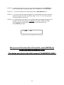
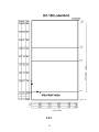
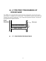
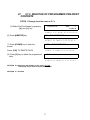
44. 2.7 PRE-PRINT PROGRAMMING OF
VENDOR NAME
The LABEL end is reserved [10mm area] for fixed (pre-printing) data, such as vendor name,
plant location, or company motto, can be printed. To print data the contents, print position and
character size must be programmed. Up to 3 lines can be printed in this area. One line can
be programmed 32 digits at maximum.
Print
Direction
Back paper
PRE-PRINTING AREA
10mm
END - 64 mm
45.
2.7.1. PRE-PRINTED PROGRAM FIELDS
53
THERMAL
PRINT
HEAD
54
46. 2.7.2. PROGRAMMING FOR PRE-PRINT NAMES
1. Enter PRG mode.
PRG :
ID CODE
. . . . . . . . . . . . . . . . . . . .
Z S N K 1 2 3 I RM I 0 1 2 3 4 5 6 7 8
PRG :
2. Select pre-print name with [TARE←
←] or
[UNIT WEIGHT→
→] keys.
PRE-PRINTED NAME
. . . . . . . . . . . . . . . . . . . .
Z S N K 1 2 3 I R M I 0 1 2 3 4 5 6 7
8
PRE-PRINT NAMES
3. Press [∗
∗/ENTER] key.
. . . . . . . . . . . . . . . . . . . .
Z S R K 1 2 3 I RM I
0 1 2 3 4 5 6 7
8
CONTENTS
=NO.
1
♦♦♦♦♦
. . . . . . . . . . . . . . . . . . . .
4. Press [∗
∗/ENTER] key.
Z S N K 1 2 3 I R M I
8
0 1 2 3 4 5 6 7
♦= Blinking cursor
5. Select line no. by pressing
[ + ]and [ − ] key 1/2/3
CONTENTS
= NO.
2
♦♦♦♦♦
. . . . . . . . . . . . . . . . . . . .
Z S N K 1 2 3 I RM I 0 1 2 3 4 5
8
6 7
C1=
6. Press [∗
∗/ENTER] key.
. . . . . . . . . . . . . . . . . . . .
Z S N K 1 2 3 I RM I 0 1
8
7. Enter A/N data by key entry.
ie. DIGI MATEX INC.
C1=
2 3 4 5 6 7
DIGI MATEX INC.
. . . . . . . . . . . . . . . . . . . .
Z S N K 1 2 3 I R M I 0 1 2 3 4 5 6 7 8
55
CONTENTS
=NO.
2
♦♦♦♦♦
. . . . . . . . . . . . . . . . . . . .
8. Press [∗
∗/ENTER] key to enter the data into
memory. Press A/M key to return to
previous screen
Z S N K 1 2 3 I RM I 0 1 2 3 4 5 6 7 8
CONTENTS
=NO. 3
♦♦♦♦♦
. . . . . . . . . . . . . . . . . . . .
9. Select next Contents no. With [+
+ ] or
[−
−] key. Enter data for next line,
Repeat for last line
ie. 80 Oak St. Norwood, NJ
Z S N K 1 2 3 I RM I 0 1 2
3 4 5 6 7 8
CONTENTS
=NO.
3
♦♦♦♦♦
. . . . . . . . . . . . . . . . . . . .
10. Select Contents no. with [TARE←
←] or
[UNIT WEIGHT→
→] keys to enter data to other
lines, if need.
Z S N K 1 2 3 I RM I 0 1 2
3 4 5 6 7 8
ie. Tel 201-784-3400
11. Press [∗
∗/ENTER] key to save in Memory, then [AUTO/MANUAL] key to return to
previous screen.
NOTE: " To return to previous diaplay press [AUTO/MANUAL] key.
Enter entire line of data before pressing [∗/ENTER].
56
47.
2.7.3. DELETION OF PROGRAMMED PRE-PRINT
CONTENTS
STEPS 1 Through 4 are the same as 2.7.2
(5) Select Pre-Print Names by pressing
[ + ] and [ − ] key
CONTENTS
=NO.
1
♦♦♦♦♦
. . . . . . . . . . . . . . . . . . . . .
Z S N K 1 2
(6) Press [∗
∗/ENTER] key.
3 I R I M I 0 1 2 3 4 5 6 7 8
C1 = DIGI MATEX INC.
. . . . . . . . . . . . . . . . . . . .
Z S N K 1 2 3 I R M I 0 1 2 3 4 5 6 7 8
DEL= DIGI MATEX INC.
(7) Press [CLEAR] key to clear the
screen.
. . . . . . . . . . . . . . . . . . . .
Press [Y/N] TO DELETE DATA
Z S N K 1 2 3 I RM I 0 1 2 3 4 5 6 7 8
C 1=
(8) Press [Y] key to delete the programmed
data.
. . . . . . . . . . . . . . . . . . . .
Z S N K1 2 3 I R M I 0 1 2 3 4 5 6 7 8
NOTE) " To escape from the deletion screen, press [ N ] key.
The display will go back to the previous screen.
NOTE) " C = Contents
57
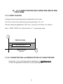
48. 2.7.4. PRINT POSITION AND CHARACTER SIZE OF PREPRINT NAME.
2.7.4.1 PRINT POSITION
Printing position of pre-printing name is decided with X and Y value.
The X and Y value is the interval from the start point where X=0, Y=0.
The both values are graduated by “DOT” size. (one dot is X=0.135mm, Y=0.135mm)
Note: " PRINT SPECS No. 24 must be set to “Y” to print vendor name.
Y
ITEM DATA AREA
PRE-PRINT DATA
x
y
0,0
X
⇓ label printing
direction
2.7.4.2. CHARACTER SIZE and MAGNIFICATIONS OF CHARACTER SIZE
Please refer to size of character and the magnification on APPENDIX II & III
to select the appropriate combination for your preprinting data.
58
2.7.4.3. DISPLAY OF PROGRAMMING SCREEN SAMPLE
C1= X.
∇∇∇
0. / Y
0. / S . 0 / M . 0
∇∇∇∇
♦♦♦
♦♦♦
Printing position (X value, horizontal)
* Numeric key entry
Printing position (Y value, vertical)
* Numeric key entry
Character size
* Selection (S.0 ~ S.5) with [+],[-] keys
Magnification of character
* Selection (M.0 ~ M.2) with [+],[-] keys
Note) Disable printing of data, set the printing position with “ 0 “ value for X and Y.
2.7.4.4. PROGRAMMING PRE-PRINTED COORDINATES
1. Enter PRG mode and select pre-print
name. Press [TARE←
←] or [UNIT WEIGHT→
→]
key
PRG :
PRE-PRINTED
NAME
. . . . . . . . . . . . . . . . . . . .
Z S N K 1 2 3 I R M I 0 1 2 3 4 5 6 7 8
PRE-PRINT NAMES
2. Press [∗
∗/ENTER] key.
. . . . . . . . . . . . . . . . . . . .
3. Press [TARE←
←] or [UNIT WEIGHT→
→] key
to enter “PRINT COORDINATE” screen.
Z S N K 1 2 3
I RM I 0 1 2 3 4 5 6 7 8
PRE-PRINT
COORDINATE
. . . . . . . . . . . . . . . . . . . .
Z S N K 1 2 3 I R M I 0 1 2 3 4 5 6 7 8
COORDINATE
= NO.
1
♦♦♦♦♦
. . . . . . . . . . . . . . . . . . . .
4. Press [∗
∗/ENTER] key.
(NOTE: LOOP THRU 1-2-3 LINES)
with + / - key
Z S N K 1 2 3 I R M I 0 1 2 3 4 5 6 7 8
♦= Blinking cursor
59
C1 = X 120 / Y 40 / S2 / M1
∇∇∇∇∇
. . . . . . . . . . . . . . . . . . . .
5. Press [∗
∗/ENTER] to view coordinates
Z S N K 1 2 3 I RM I 0 1 2 3 4 5 6 7 8
6. Select field coordinates X/Y/S/M by pressing
[UNIT WEIGHT→
→] key to move cursor right
under
field - reverse direction with [TARE←
←]
C1 = X 120 / Y 40 / S2 / M1
∇∇∇∇∇
7. Enter X value & press [UNIT WEIGHT→
→]
key to move the cursor to right.
i.e.) X value =120
C2= X 120 / Y 20 / S 0 / M0
∇∇∇∇∇
. . . . . . . . . . . . . . . . . . . .
. . . . . . . . . . . . . . . . . . . .
Z S N K 1 2 3 I RM I 0 1 2 3 4 5 6 7 8
Z S N K 1 2 3 I
M I 0 1 2 3 4 5 6 7 8
C2= X. 120 / Y
20 / S 0 / M0
♦♦
. . . . . . . . . . . . . . . . . . . .
8. Enter Y value & press [UNIT WEIGHT→
→]
key to move the cursor to right.
i.e.) Y value = 20
Z S N K 1 2 3 I RM I 0 1 2 3 4 5 6 7
9. Select character size by pressing [+
+] or [−
−] key
& press [UNIT WEIGHT→ ] key to move cursor.
i.e.) Character size = S0
8
C2= X. 120 /Y.
20 / S.0 / M0
♦♦
. . . . . . . . . . . . . . . . . . . .
Z S N K 1 2 3 I R M
I 0 1 2 3 4 5 6 7 8
C2= X. 120 /Y.
20 / S.0 / M1
♦♦
. . . . . . . . . . . . . . . . . . . .
10. Select magnification by pressing [+
+] or [−
−]
key.
i.e.) Character size = M1
Z S N K 1 2 3 I R M I 0 1 2 3 4 5 6 7 8
11. Press [∗
∗/ENTER] key to enter the data into
the memory file.
i.e.) SAMPLE 10mm Area
FIELD TITLE
=
NO. 3
♦♦♦♦♦
. . . . . . . . . . . . . . . . . . . .
Z S N K 1 2 3 I RM I 0 1 2 3 4 5 6 7 8
DIGI MATEX, INC.
- C1 = X 120 / Y 40 / S.2 / M1
- C2 = X 80 / Y 20 / S.0 / M1
- C3 = X 130 / Y 1 / S.0 / M1
80 Oak Street, Norwood, NJ 07648
Tel: 201-784-3400
VENDOR NAME WITHIN COORDINATES
60
49.
2.8. COPY OF STANDARD
FORMAT(FORMAT-COPY)
If the label format you need to design is similar to a standard format, you can make a new
format easily by copying the standard format then re-arranging the print position and character
size of the data in a NEW FREE format design.
When you select the standard format to copy to, refer to the list of standard format in
APPENDIX I.
1. Enter PRG mode and select a format
PRG : FORMAT - COPY
to copy
. . . . . . . . . . . . . . . . . . . .
Z S N K 1 2 3
2. Press [∗
∗/ENTER] key.
I R M I 0 1 2
3 4 5 6 7 8
(ST = STD.)
(FR = FREE FORMAT)
CPY = ST NO. 1 → FR
NO. 1
♦♦♦♦♦
. . . . . . . . . . . . . . . . . . . .
Z S N K 1 2 3 I R M I 0 1
2 3 4 5
6 7 8
◊= Blinking cursor
3. Select standard format no. to copy with
[+
+] or [−
−] key. i.e.) standard no. 3
CPY = ST NO. 3 → FR
NO. 1
♦♦♦♦♦
. . . . . . . . . . . . . . . . . . . .
Z S N K 1 2 3
4. Move the cursor by pressing
[UNIT WEIGHT→
→] key.
I R M I 0 1 2 3 4 5 6 7 8
CPY = ST NO. 3 → FR NO.
1
♦♦♦♦♦
. . . . . . . . . . . . . . . . . . . .
Z S N K 1 2 3 I R M I 0 1 2 3 4 5 6 7 8
5. Select free format no. to copy with
[ + ] or [ − ] key. i.e.) free format no.2
CPY = ST NO. 3 → FR NO.
2
♦♦♦♦♦
. . . . . . . . . . . . . . . . . . . .
Z S N K 1 2 3 I R M I 0 1 2 3 4 5 6 7 8
PRG : FORMAT - COPY
6. Press [∗
∗/ENTER] key to enter the data
into the memory file.
. . . . . . . . . . . . . . . . . . . .
Z SN K 1 2 3 I RM I 0 1 2 3 4 5 6 7 8
61
50. 2.9. FREE FORMAT PROGRAMMING
DC-150 has 7 types of standard formats, so that you can select the label format suited to your
needs. However, in the case that none of the standard formats is suited to the user's needs,
you can make a new label format. Two free formats are possible.
According to the usage of the machine, DC-150 can print 3 types of labels: ITEM LABEL,
TOTAL LABEL AND GROSS LABEL. The data base of one label format has all 3 types of
labels. When you make a new label format, the format data for Item, Total and Gross labels
are saved as one data base. To make a new label format: label size, print angle, print
position, character size must be programmed.
51.
2.9.1. TYPE OF LABELS
In operation mode, the DC-150 can print all 3 standard types of labels.
1. ITEM LABEL
... Issued in SINGLE OPERATION
2. TOTAL LABEL ... Issued in MULTIPLE TRANSACTION with + and - keys in
3. GROSS LABEL ... Issued in GROSS WEIGHT OPERATION
52.
2.9.2. LABEL SIZES
You can select a label size from 11 sizes listed in Print Spec 34.
The standard frequently used label width is 64mm.
P/N
L-52
L-53
L-54
mm
64 x 55
64 x 77
64 x 120
Inches
(2-1/2” x 2-1/4”)
(2-1/2” x 3-00”)
(2-1/2” x 4-1/2”)
Example:
L - 52
62
53.
54. 2.9.3. CUSTOM FREE FORMAT SAMPLE LABEL
63
55.
2.9.3. CUSTOM FREE FORMAT SAMPLE
LABEL(CONTINUED)
64
56.
57. 2.9.4. PROGRAMMABLE DATA FOR EACH LABEL
This chart shows which data fields are printed on the three (3) standard types of labels.
KEY: O = Available, X = N/A
ITEM
DATA
ITEM
LABEL
TOTAL
LABEL
GROSS
LABEL
DATA
TYPE
ID CODE
|
|
|
|
|
|
|
|
|
|
|
|
|
|
|
X
X
|
|
|
|
|
|
|
|
|
|
|
|
|
|
|
X
|
|
|
|
|
|
|
X
X
X
X
X
X
|
|
|
|
|
|
|
X
X
X
X
X
X
|
|
|
|
|
X
X
X
X
X
|
|
|
|
|
|
|
X
X
X
X
X
X
X
X
|
|
X
X
X
X
X
X
X
X
X
X
|
|
|
X
|
X
|
|
|
|
X
|
TYPE 1
TYPE 2
TYPE 2
TYPE 2
TYPE 1
TYPE 1
TYPE 1
TYPE 1
TYPE 1
TYPE 1
TYPE 1
TYPE 1
TYPE 1
TYPE 1
TYPE 1
TYPE 1
TYPE 1
TYPE 1
TYPE 1
TYPE 1
TYPE 1
TYPE 1
TYPE 1
TYPE 1
TYPE 3
TYPE 3
TYPE 3
TYPE 3
TYPE 3
TYPE 3
TYPE 3
TYPE 3
TYPE 1
TYPE 1
TYPE 1
TYPE 1
PART NO.
PARTS NAME
LOT NO.
WEIGHT
WEIGHT UNIT (g/ LB)
“/” MARK FOR WEIGHT
RIGHT
RIGHT UNIT (g/ lb)
“-” MARK FOR QTY
QUANTITY
QUANTITY UNIT (symbol)
DATE
TIME
TASK CONTENTS (in/out/n.a.)
SUM TOTALING
SUM COUNT
GROSS WEIGHT
GROSS UNIT (g/lb)
NET WEIGHT
NET UNIT (g/lb)
TARE WEIGHT
TARE UNIT (g/lb)
SEQUENCE NO. DATA
BAR-CODE (ID)
BAR-CODE (PART NO)
BAR-CODE (LOT NO.)
BAR-CODE (QTY)
BAR-CODE (TARE)
BAR-CODE (RIGHT)
BAR-CODE (GROSS WEIGHT)
BAR-CODE (NET WEIGHT)
FIELD TITLE #1 ~ 3
FIELD TITLE #4 ~ 7
FIELD TITLE #8
FIELD TITLE #9 ~11
65
ITEM
DATA
ITEM
LABEL
TOTAL
LABEL
GROSS
LABEL
DATA
TYPE
FIELD TITLE #12
|
|
X
X
X
X
X
X
X
|
|
|
X
X
X
X
X
X
X
|
X
|
|
|
|
|
|
|
|
|
TYPE 1
TYPE 1
TYPE 1
TYPE 1
TYPE 1
TYPE 1
TYPE 1
TYPE 1
TYPE 1
TYPE 1
FIELD TITLE #13 ~16
GROSS WEIGHT (GROSS)
GROSS UNIT (GROSS)
RIGHT (GROSS)
NET WEIGHT (GROSS)
NET UNIT (GROSS)
TARE WEIGHT (GROSS)
TARE UNIT (GROSS)
ADDRESS CONTENTS #1~ 5
NOTE 1)
" In multiple transaction, item label is printed with [+] or [-] keys. Minus mark is printed on label .
NOTE 2) " TASK CONTENTS is "IN " , " OUT " , " NON - ADD ".
58.
2.9.5. PRINTING POSITION
Printing position of item data is decided with X and Y value.
The X and Y value is the interval from the start point where X=0, Y=0.
Both values are graduated by a dot size. (One dot is X = 0.135mm , Y = 0.135mm)
Y
x
ITEM DATA FIELDS
y
(0,0)
X
Reserved
10mm
PRE-PRINTED AREA
⇓ label printing
direction
START
POINT
NOTE 1) " The item data can not be printed on the bottom 10mm of label.
This is reserved for pre-printed name.
NOTE 2) " The printing position of item data is set from the start point where X = O and Y = O.
66
59.
2.9.6. LABEL ANGLE AND BAR-CODE ANGLE
All item data can be printed in 4 different directions by changing label angle. Bar-code data
printing direction can be programmed independently in each label data base.
y
y
x
ITEM DATA
(0,0) y
DIGI MATEX, INC. (PRE-PRINT)
x
DIGI MATEX, INC. (PREPRINT)
A1 = 0 degree
y
(0,0
A2 = 90 degree
y
y
x
x
x
y
y
(0,0)
DIGI MATEX INC. (PRE-PRINT)
DIGI MATEX INC. (PREPRINT)
A-3 = 180 degree
x
A4 = 270 degree
(0,0)
CHARACTER SIZE and MAGNIFICATIONS (HEIGHT OF BAR-CODE)
Refer to the list of character sizes in APPENDEX II, III & IV to select the
combination of character size and magnification for printing data.
Height of Bar-Code can be selected from: 10mm, 15mm, 20mm, 25mm, 30mm.
67
60.
2.9.7. DATA TYPE
every field can have different characteristics, therefore, data can vary from lable format to label
format.
Three types of data can vary; “human readables”, “Field Titles” and “Bar Codes”.
KEY: O = Available X = N/A
DATA TYPE
X position
Y position
Character size
Magnification of character
Line number
Max. digits in the selected line
Height of bar-code
Print angle of bar-code
HUMAN
READABLE
TYPE 1
TITLES
TYPE 2
BAR
CODE
TYPE 3
|
|
|
|
X
|
X
X
|
|
|
|
|
|
X
X
|
|
X
X
X
|
|
|
Line No. and Digit are selectable for Lot NO, Part Name, Part No.
Bar Code Printing Spec’s are selectable.
68
2.9.8.
LABEL FORMAT GRID LAYOUT CHART
DC-150 PRINTING COORDINATES
DATA FIELD
#
1
2
3
4
5
6
7
8
9
10
11
12
13
14
15
16
17
18
19
20
21
22
23
24
25
26
27
28
29
30
31
32
33
34
35
36
37
38
39
40
41
42
L
D
X
Y
S
M
LINE
NO.
# OF
DIGITS
POSITION
POSITION
SIZE
OF
CHAR.
MAGNIFY
PRINT ANGLE
°
ID CODE
PART NO.
“
“
“
“
“
“
PARTS NAME
“
“
“
“
“
“
LOT NO.
“
“
“
“
“
“
WEIGHT
WEIGHT UNIT
“/”MARK FOR WT
UNIT WEIGHT
UNIT WT. UNIT
“-”MARK FOR QUAN
QUANTITY
QUANTITY UNITS
DATE
TIME
TASK CONTENTS
SUM TOTAL
SUM COUNT
GROSS WEIGHT
GROSS WT.UNITS
NET WEIGHT
NET WEIGHT UNITS
TARE WEIGHT
TARE WT. UNITS
SEQUENCE NO.
ID BARCODE
PART NO. BARCODE
LOT NO. BARCODE
QUAN. BARCODE
TARE WT.BARCODE
UNIT WT.BARCODE
GROSS
WT.BARCODE
NET WT. BARCODE
69
H
BAR CODE
HEIGHT
A
BAR
CODE
ANGLE
#
43
44
45
46
47
48
49
50
51
52
53
54
55
56
57
58
59
60
61
62
63
64
65
66
67
68
69
DATA FIELD
CONTENTS
X
Y
S
M
H
A
POSITION
POSITION
SIZE OF
CHAR.
MAGNIFY
BAR CODE
HEIGHT
BAR CODE
ANGLE
TITLE CONTENTS 1
TITLE CONTENTS 2
TITLE CONTENTS 3
TITLE CONTENTS 4
TITLE CONTENTS 5
TITLE CONTENTS 6
TITLE CONTENTS 7
TITLE CONTENTS 8
TITLE CONTENTS 9
TITLE CONTENTS 10
TITLE CONTENTS 11
TITLE CONTENTS 12
TITLE CONTENTS 13
TITLE CONTENTS 14
TITLE CONTENTS 15
TITLE CONTENTS 16
GRS. WT(GRS
LABEL)
GRS UN(GRS LABEL)
NET WT. (GRS
LABEL)
NET UN(GRS LABEL)
TARE WT(GRS
LABEL)
TARE UN(GRS
LABEL)
ADDRESS CONTENT
1
ADDRESS CONTENT
2
ADDRESS CONTENT
3
ADDRESS CONTENT
4
ADDRESS CONTENT
5
70
61.
62. 2.9.9. PROGRAMMING SCREEN
Programming screen for data type 1 - Human Readables.
X.=
0. / Y=
∇∇∇
0. / S . 0 / M . 0
∇∇∇∇
♦♦♦
♦♦♦
♦ = Blinking cursor
Printing position (X value, horizontal)
∗ Numeric key entry
Printing position (Y value, vertical)
∗ Numeric key entry
Character size
∗ Selection (S.0 ~ S.5)
Magnification of character
∗ Selection (M.0 ~ M.2)
Programming screen for data type 2 - Human Readables
L.4 / D. 0 8 / X. 4 6 7
♦ ♦
∇∇∇
♦
∇∇∇
M.0
♦♦♦
♦ = Blinking cursor
Line number
∗ Selection (L.1 ~ L.4)
The number of digits in the line
∗ Numeric key entry (0~ 32)
Horizontal/vertical selection
∗ Selection (X , Y)
Printing position (X value or Y value)
∗ Numeric key entry
Character size/ Magnification selection
* Selection (S. or M.)
Character size or Magnification size
* Selection (S.=S.0~S.5/M.= M.0~M.2)
71
Programming screen for data type 3 - Bar Code
X.=
0. / Y=
∇∇∇
0. / H.4 /
∇∇∇∇
♦♦♦
A.3
♦♦♦
♦ = Blinking cursor
Printing position (X value, horizontal)
* Numeric key entry
Printing position (Y value, vertical)
* Numeric key entry
Height of bar-code
* Selection (H.0~H.4)
Printing angle of bar-code
* Selection (A.0 ~ A.3)
* Selection of height of bar-code
H.0 = 10mm, H.1 = 15mm, H.2 = 20mm, H.3 = 25mm, H.4 = 30mm)
* Selection of printing angle of bar-code
A.0 = 0 degree, A.1 = 90 degree, A-2 =180 degree, A.3 = 270 degree
63.
2.9.10. KEY FUNCTION
[UNIT WEIGHT/→
→] key and [TARE←
←] key
To select item data in loop routine
To move the cursor in a display
[+
+ ] and [−
−] key
To select data when triangle cursor indicator is blinking
[AUTO /MANUAL] key
To move back to the previous screen.
[SPACE / kg/lb.] key
To print the test label of item label in item data setting
[CODE / RETRY] key
To print the test label of total label in item data setting.
[M NET/GROSS] key
To print the test label of gross label in item data setting.
[PIECES] key
To print the test label of item label with minus mark for quantity in item data setting
72
64.
2.9.11. PROGRAMMING OPERATION
1. Enter PRG mode and select free format.
PRG :
FREE FORMAT
. . . . . . . . . . . . . . . . . . . .
Z S R K 1 2 3 I R I M I 0 1 2
F. F =
2. Press [∗
∗/ENTER] key.
FREE
3 4 5 6 7 8
FORMAT 1
. . . . . . . . . . . . . . . . . . . . .
Z S R K 1 2 3 I R I M I 0 1 2 3 4 5 6 7 8
3. Select FREE FORMAT # by pressing
[UNIT WEIGHT→
→] or [TARE←
←] key.
F.F =
FREE
FORMAT 2
. . . . . . . . . . . . . . . . . . . . .
Z S R K 1 2 3 I R I M I 0 1
4. Press [∗
∗/ENTER] key.
FM2 = PRINT ANGLE
5. Press [∗
∗/ENTER] key.
FM2 = ANGLE (°)
2 3 4 5 6 7 8
0
♦♦♦
. . . . . . . . . . . . . . . . . . . . .
Z S R K 1 2 3 I R I M
.6. Select label angle by pressing
[ + ] or [ − ] key.
I 0 1 2 3 4 5 6 7 8
FM2 = ANGLE (°)
180
♦♦♦
. . . . . . . . . . . . . . . . . . . . .
Z S R K 1 2 3 I R I M I 0 1 2 3 4 5 6 7 8
FM2 = ID CODE
7. Press [∗
∗/ENTER] key.
(Ready for setting the print positions for
item data)
. . . . . . . . . . . . . . . . . . . . .
Z S R K 1 2 3 I R I M I 0 1 2 3 4 5 6 7 8
8. Select item data by pressing
[UNIT WEIGHT→
→] or [TARE←
←] key.
FM2 = PART NAME
. . . . . . . . . . . . . . . . . . . . .
Z S R K 1 2 3 I R I M I 0 1 2 3 4 5 6 7 8
Note) " It is possible to omit any factors, if not necessary.
73
Start for A. Programming operation for item data ( data type 1)
9. Select programming factor.
Ex) ID CODE
FM2 = ID CODE
. . . . . . . . . . . . . . . . . . . . .
Z S R K 1 2 3 I R I M I 0 1 2 3 4 5 6 7 8
ID= X. 0 /Y.=
0. / S.0 / M0
∇ ∇ ∇
. . . . . . . . . . . . . . . . . . . . .
10. Press [∗
∗/ENTER] key.
Z S R K 1 2 3 I R I M I 0 1 2 3 4 5 6 7 8
11. Enter X value and press [UNIT WEIGHT→
→]
key to move the cursor to right.
i.e.) X value = 52
ID= X. 5 2 /Y.=
0. / S.0 / M0
∇∇∇∇
. . . . . . . . . . . . . . . . . . . . .
Z S R K 1 2 3 I R I M I 0 1 2 3 4 5 6 7 8
12. Enter Y value and press [UNIT WEIGHT→
→]
key to move the cursor to right.
i.e.) Y value = 15
ID= X. 5 2 /Y.=
1 5. / S.0 / M0
♦♦♦
. . . . . . . . . . . . . . . . . . . . .
Z S R K 1 2 3 I R I M I 0 1 2 3 4 5 6 7 8
13. Select character size by pressing [ + ] or
[ − ] key & press [UNIT WEIGHT→
→] key to
move Cursor.
i.e.) Character size = S2
ID= X. 5 2 /Y.=
15 / S.2 / M0
♦♦♦
. . . . . . . . . . . . . . . . . . . . .
14. Select magnification by pressing [ + ] or [ − ]
key.
i.e.) Character size = M2
ID= X. 5 2 /Y.=
Z S R K 1 2 3 I R I M I 0 1 2 3 4 5 6 78
15 / S.2 / M 2
♦♦♦
. . . . . . . . . . . . . . . . . . . . .
Z S R K 1 2 3 I R I M I 0 1 2 3 4 5 6 7 8
ID= X. 5 2 /Y.=
15 / S.2 / M 2
♦♦♦
. . . . . . . . . . . . . . . . . . . . .
15. Press [M], [SPACE] and [CODE] keys to
check print position with test label
i.e.) Character size = M2
Z S R K 1 2 3 I R I M I 0 1 2 3 4 5 6 7 8
16. Press [∗
∗/ENTER] key to enter the data into
the memory file.
Ready for setting the next item data
FM2 = PART NO.
. . . . . . . . . . . . . . . . . . . . .
Z S R K 1 2 3 I R I M I 0 1 2 3 4 5 6 7 8
74
Repeat for
B.
Programming operation for item data (data type 2)
9. Select programming factor.
I.e.) PART NO.
FM2 = PART NO.
. . . . . . . . . . . . . . . . . . . . .
Z S R K 1 2 3 I R I M I 0 1 2 3 4 5 6 7 8
P.N.O.= L.1 / D. 0 / X.
0 / S .0
♦♦
. . . . . . . . . . . . . . . . . . . . .
10. Press [∗
∗/ENTER] key.
Z S R K 1 2 3 I R I M
11. Select line no. by pressing [ + ] or [ − ] key
and press [UNIT WEIGHT→
→] key to move cur.
i.e.) Line no. = 1
I 0 1 2 3 4 5
6 7 8
N.O.= L.1 / D. 0 / X.
0 / S .0
∇∇∇
. . . . . . . . . . . . . . . . . . . . .
Z S R K 1 2 3 I R I M
I 0 1 2 3 4 5
6 7 8
12. Enter the number of digits for the selected
line and press [UNIT WEIGHT→
→] key to move
Cursur to value entry.
i.e.) The number of digits = 8
P.N.O.= L.1 / D. 8 / X.
0 / S .0
∇∇∇∇
. . . . . . . . . . . . . . . . . . . . .
13. Enter X value and press [TARE←
←] key to
move the cursor back to X/Y selection.
i.e.) X= 64
P.N.O.= L.1 / D. 8 / X. 64 / S .0
♦
. . . . . . . . . . . . . . . . . . . . .
Z S R K 1 2 3 I R I M
Z S R K 1 2 3 I R I M
14. Press [ + ] or [ − ] key to enter Y value &
press [UNIT WEIGHT→
→] key to move cursor to
right.
4 5
6 7 8
I 0 1 2 3 4 5 6 7
8
P.N.O.= L.1 / D. 8 / Y.
0 / S .0
∇∇∇∇
. . . . . . . . . . . . . . . . . . . . .
Z S R K 1 2 3 I R I M
15. Enter Y value and press [UNIT WEIGHT→
→]
key to move the cursor to character size entry.
i.e.) Y = 123
I 0 1 2 3
I 0 1 2 3 4 5
6 7 8
P.N.O.= L.1 / D. 8 / Y. 1 2 3 / S .0
♦
. . . . . . . . . . . . . . . . . . . . .
Z S R K 1 2 3 I R I M
I 0 1 2 3
4 5 6 7 8
P.N.O. = L.1 / D. 8 / Y. 1 2 3 / S . 1
♦
. . . . . . . . . . . . . . . . . . . . .
16. Select character size and press [TARE←
←]
key to move cursor back to S./M. selection.
i.e.) Character size = S.1
Z S R K 1 2 3
75
I R I M I 0 1 2 3 4 5 6 7 8
CONTINUE
17. Press [ + ] or [ − ] key to enter M. value &
press [UNIT WEIGHT→
→] key to move
Cursor to right.
P.N.O.= L.1 / D. 8 / Y. 1 2 3 / M . 0
♦
. . . . . . . . . . . . . . . . . . . . .
Z S R K 1 2 3 I R I M I 0 1 2 3 4 5 6 7 8
18. Select Magnification value.
I.e.) M. =2
P.N.O.= L.1 / D. 8 / Y. 1 2 3 / M. 2
♦
. . . . . . . . . . . . . . . . . . . . .
Z S R K 1 2 3 I R I M
I 0 1 2 3 4 5 6 7 8
P.N.O. =
L.1 /D. 8/ Y.123 / M. 2
♦
. . . . . . . . . . . . . . . . . . . . .
20. Press [M], [SPACE] and [CODE] keys to
check print position with test label
Z S R K 1 2 3 I R I M I 01 2 3 4 5 6 7 8
21. If you need to set the data for line 2 ~ 4,
press [TARE←
←] key to move cursor to line no.
selection and set the data as the same
program procedure.
P.N.O.= L.2 / D. 0 / X.
0 / S .0
♦♦
. . . . . . . . . . . . . . . . . . . . .
Z S R K 1 2 3 I R I M
22. Press [∗
∗/ENTER] key to enter the data into
the memory file.
(Ready for setting the next item data)
I 0 1 2 3 4 5 6 7 8
FM2 = PART NAME
. . . . . . . . . . . . . . . . . . . . .
Z S R K 1 2 3 I R I M I 0 1 2 3 4 5 6 7 8
76
Repeat for C.
Programming operation for item data ( data base type 3)
9. Select programming factor.
I.e.) BAR-CODE (ID)
FM2 = BARCODE (ID)
. . . . . . . . . . . . . . . . . . . . .
Z S R K 1 2 3 I R I M I 0 1 2 3 4 5 6 7 8
B.ID= X. 0 /Y.
0. / H.0 / A.0
∇ ∇ ∇
. . . . . . . . . . . . . . . . . . . . .
10. Press [∗
∗/ENTER] key.
Z S R K 1 2 3 I R I M
11. Enter X value and press [UNIT WEIGHT→
→]
key to move the cursor to right.
i.e.) X value = 85
B.ID= X. 8 5 /Y.
0. / H.0 / A.0
∇ ∇ ∇ ∇
. . . . . . . . . . . . . . . . . . . . .
Z S R K 1 2 3 I R I M
12. Enter Y value and press [UNIT WEIGHT→
→]
key to move the cursor to right.
i.e.) Y value = 236
I 0 1 2 3 4 5 6 7 8
I 0 1 2 3 4 5 6 7 8
B.ID= X. 8 5 /Y.
2 3 6/ H.0 / A.0
♦♦
. . . . . . . . . . . . . . . . . . . . .
Z S R K 1 2 3 I R I M I 0 1 2 3 4 5 6 7 8
13. Select height of barcode by pressing [ + ] or
[ − ] key and press [RIGHT→] key to move
cursor.
i.e.) Height of bar-code = 25mm (2)
14. Select angle of barcode by pressing [ + ] or
[ − ] key i.e.) Angle of bar-code = 0 degree (0)
B.ID= X. 8 5 /Y.
2 3 6/ H.2 / A.0
♦♦
. . . . . . . . . . . . . . . . . . . . .
Z S R K 1 2 3 I R I M
I 0 1 2 3 4 5 6 7 8
B.ID= X. 8 5 /Y.
2 3 6 / H.2/ A.0
♦♦
. . . . . . . . . . . . . . . . . . . . .
Z S R K 1 2 3 I R I M I 0 1 2 3 4 5 6 7 8
B.ID= X. 85 /Y.
2 3 6 / H.2 / A.0
♦♦
. . . . . . . . . . . . . . . . . . . . .
15. Press [MNET/GROSS], [SPACE] and
[CODERETRY] keys to check print position with
test label.
Z S R K 1 2 3 I R I M
16. Press [∗
∗/ENTER] key to enter the data into
the memory file.
I 01 2 3 4 5 6 7 8
FM2 = PART NO.
. . . . . . . . . . . . . . . . . . . . .
Z S R K 1 2 3 I R I M
77
I 0 1 2 3 4 5 6 7 8
65. 2.9.12. PROGRAMMING PROCEDURE (USING COPY
FUNCTION)
A. After designing the label format, select the most similar format from the standard formats in
appendix I.
B. List up the print data to change from the standard format. (deletion, addition, change of
position and character size)
C. Set up the label size in maintenance mode.
D. Copy the standard format in FORMAT-COPY in program mode.
E. Change the format in FREE FORMAT in program mode.
Standard format #3
Standard format #6
78
B.
THE LIST OF LABEL FORMAT TO CHANGE
DATA
ID CODE
P. NO.
(L1)
LOT NO.
(L1)
PART NAME
(L1)
(L2)
BARCODE(ID)
TEXT 6
ACTION
DELETE
DELETE
Digits no. X position
0⇒ 0
32
0⇒ 0
Y position
162 ⇒ 0
210 ⇒ 0
S size
S1
S1
M size
M2
M1
DELETE
32
0⇒ 0
134 ⇒ 0
S1
M1
CHANGE
ADD
32 ⇒ 16
0 ⇒ 16
0⇒ 0
0⇒ 0
238 ⇒ 275
0 ⇒ 230
S1
S1
M1
M1
0 ⇒ 150
0 ⇒ 150
H0
S1
A0
M1
ADD
ADD
0 ⇒ 100
0⇒ 0
C. Set “64mm x55mm” on address 34 (size of label format) in PRINT SPEC in MAINTENANCE
MODE. Refer to 3-3 METHOD OF PROGRAM.
D. Copy the standard format #2 to free format #1. Refer to 2-8 COPY OF STANDARD
FORMAT.
E. Change the print data of label format data. Refer to 2-9 FREE FORMAT PROGRAM.
E-1 Select free format ............... No.1.
E-2 Set angle of label format ...... 0 degree
E-3 Change the print position for ID code at (X=0, Y=0) to delete.
E-4 Change the print position for part no. at ( X=0, Y=0) to delete.
E-5 Change the print position for lot no at ( X=0,Y=0) to delete.
E-6 Change the data for part name. (L1/ D=16, X=0, Y=275, S1, M1)
(L2/ D=16, X=0, Y=230, S1, M1)
E-7 Change the data for barcode of ID code. ( X=100, Y=150, H=0, A=0)
E-8 Change the data for text 6. (X=0, Y=150, S1, M1)
NOTE)" After changing each print data, we recommend, you would check with the test print if the print position
and character size are fit for the layout. If they are not, adjust the print position in programming step.
SAMPLE OF TEST LABEL
79
66. 2.10. SHELF LOCATION LABEL
PROGRAM
To know the location of stock, each item code can be assigned shelf location number. DC-150
can print the shelf location label for each item code in Check Mode to put on the shelves where
the stock is stored.
DC-150 has no standard format, use one free format for this shelf location label. The label
format is to be developed with the same programming steps as free format.
67.
2.10.1. LABEL SIZE
You can select label size from 11 size in Spec. 34, which is in common with label size of free
format. (Ref. to 2.9.2. LABEL SIZE in Free Format Program)
68.
2.10.2. PROGRAMMABLE ITEM DATA
In shelf location label, you can program angle, print factors, print position, and character size of
selected factors from the following list.
PRINTING FACTORS
ID CODE
PARTS NO.
PARTS NAME
UNIT WEIGHT
LOCATION NO.
THRESHOLD
DATE
TIME
BAR-CODE (ID)
BAR-CODE (PARTS NO.)
FIELD TITLE NO.1 ~ 16
69.
DATA TYPE
TYPE 1
TYPE 2
TYPE 2
TYPE 1
TYPE 1
TYPE 1
TYPE 1
TYPE 1
TYPE 3
TYPE 3
TYPE 1
2.10.3. PRINT POSITION
The printing position of item data on shelf location label is the same as on free format.
(Ref. to 2.9.4 PRINT POSITION in Free Format Program)
80
70.
71. 2.10.4. LABEL ANGLE and BAR-CODE ANGLE
Shelf location label and bar-code can be printed in 4 different angles in the same as free
format.
(Ref. to 2.9.5 Label Angle and Bar-code Angle in Free Format Program.)
72. 2.10.5. CHARACTER SIZE and MAGNIFICATIONS
Character size and magnification value in shelf location label is the same as in free format.
(Refer to 2.9.6 Character size and magnifications in Free Format Program)
73. 2.10.6. DATA TYPE
The data type of item data on shelf location label is the same as free format.
(Refer to 2.9.7 Data type in Free Format Program)
74. 2.10.7. PROGRAMMING SCREEN
The programming screens for item data are the same as free format.
(Refer to 2.9.8 Programming screen in Free Format Program)
75. 2.10.8. PROGRAMMING PROCEDURE
1. Enter PRG mode and select SHELF
LOCATION label heading.
PRG :
SHELF LOC. LABEL
. . . . . . . . . . . . . . . . . . . . .
Z S R K 1 2 3 I R I M I 0 1 2 3 4 5 6 7 8
S.L =
2. Press [∗
∗/ENTER] key.
PRINT ANGLE
. . . . . . . . . . . . . . . . . . . . .
Z S R K 1 2 3 I R I M
3. Press [∗
∗/ENTER] key.
I 0 1 2 3 4 5 6 7 8
S.L = ANGLE (°)
0
♦♦♦
. . . . . . . . . . . . . . . . . . . . .
Z S R K 1 2 3 I R I M
4. Select printing angle of label by pressing
[ + ] or [ −] key.
I 0 1 2 3 4 5 6 7 8
S.L = ANGLE (°)
180
♦♦♦
. . . . . . . . . . . . . . . . . . . . .
Z S R K 1 2 3 I R I M
I 0 1 2 3 4 5 6 7 8
S. L = ID CODE
5. Press [∗
∗/ENTER] key.
. . . . . . . . . . . . . . . . . . . . .
Z S R K 1 2 3 I R I M
81
I 0 1 2 3 4 5 6 7 8
6. Select printing factors by pressing
S.L = PART NAME
[TARE←
←] or [UNIT WEIGHT→
→] key.
. . . . . . . . . . . . . . . . . . . . .
Z S R K 1 2 3 I R I M I 0 1 2 3 4 5 6 78
7. Program each item data with the same operation as free format setting. Refer to
“Programming operation” in Free Format Program.
NOTE)" [Space kg/lb.] key is used for test printing of shelf location label.
76. 2.10.9. PROGRAM PROCEDURE
A. Make list of data required for shelf location label. Then layout the label roughly.
B. Set up the label size in maintenance mode.
C. Set the format in “Free Format Program” in program mode.
A-1
LABEL FORMAT
Sample of shelf
location label
82
A-2. THE LABEL FORMAT LIST FOR THE SAMPLE LABEL
Print angle = 270
DATA
ID CODE
P. NO.
(L1)
P NAME
(L1)
LOCATION NO.
BARCODE (ID)
TEXT 4
TEXT 5
TEXT 6
Digits
no.
32
32
X
Y
position position
200
50
100
380
280
100
50
200
545
650
650
686
750
750
750
50
S size
S2
S1
S1
S1
H0
S1
S1
S1
M size
M2
M1
M1
M2
A3
M2
M1
M2
B. Set “64mm x120mm” on address 34 (size of label format) in PRINT SPEC in
MAINTENANCE MODE. Refer to 3-3 METHOD OF PROGRAM.
C. Change the print data of label format data. Refer to 2-10 FREE FORMAT PROGRAM.
E-1 Set angle of label format ......
270 degree
E-2 Set the data for ID code.
(X=200, Y=600, S2, M2)
E-3 Set the data for part code.
(L1/ D=32, X=50, Y=600, S1, M1)
E-4 Set the data for part name.
(L1/ D=32,X=100, Y=600, S1,M1)
E-5 Set the data for location no.
(X=380, Y=686, S1, M2)
E-6 Set the data for bar-code of ID code
( X=280, Y=750, H0, A3)
E-7 Set the data for text 4.
( X=100, Y=750, S1, M2)
E-8 Set the data for text 5.
(X=50, Y=750, S1, M1)
E-9 Set the data for text 6.
(X=200, Y=50, S1, M1)
NOTE) " In each step on setting print data, we recommend, you would check with the test
print if the print position and character size are fit. If they are not, adjust the print
position before setting the next data.
SAMPLE OF TEST
LABEL
83
77.
2.11. SHELF LOCATION LIMIT
PROGRAM
The maximum available alpha/numeric digits of shelf location can be set, according to your
definition of the stock room. Rows, Racks, Shelves, Bins, available
By setting up the maximum limit for each digit, you compose the shelf location number.
If you enter shelf location data which does not exist in your definition, the error buzzer notices
the miss-entry and the invalid data cannot be entered in the memory file.
Programmable character and the available characters
Programmable
characters
available characters for a set
0
1
0
0, 1
9
A
0, 1, 2, 3, 4, 5 , 6, 7, 8, 9
0, 1, 2, 3, 4, 5, 6, 7, 8 , 9, A
Z
0, 1, 2, 3, 4, 5, 6, 7, 8 , 9, A ~ Z
Programming procedure for Range of Shelf location number
1. Enter PRG mode and select SHELF
LOCATION LIMIT.
PRG : SHELF LOC.
LIMIT
. . . . . . . . . . . . . . . . . . . . .
Z S R K 1 2 3 I R I M I 0 1 2 3 4 5 6 7 8
LIMIT =
2. Press [∗
∗/ENTER] key.
00 - 00 - 00 - 0 - 0
. . . . . .. . . . . . . . . . . . . . .
Z S R K 1 2 3 I R I M
I 0 1 2 3 4 5 6 7
8
3. Enter data.
I.e.) 01-15-09-A-Z
LIMIT =
011509AZ
. . . . . . . . . . . . . . . . ..
Z S R K 1 2 3 I R I M I 0 1 2 3 4 5 6 7 8
PRG: SHELF LOC. LIMIT
4. Press [∗
∗/ENTER] key
. . . . . . . . . . . . . . .. . . . . .
Z S R K 1 2 3 I R I M I 0 1 2 3 4 5 6 7 8
84
78. 2.12. ADDRESS CONTENTS
PROGRAM
DC-150 can print address data on label format #7 which has printing area for address contents.
TEN Address or Memos can be programmed. The data base file has 5 lines of 32 characters
per line. Select address file number in OPR mode, with SHIFT DOWN / N /ADDRESS KEY.
Remote address database can be interfaced through RS-232 link for thousands of addresses or
messages. Consult Factory.
79. 2.12.1. PROGRAMMING OPERATION FOR ADDRESS
CONTENTS
1. Enter PRG mode and select Address
contents.
PRG : ADDRESS CONTENTS
. . . . . . . . . . . . . . . .. . . . .
Z S R K 1 2 3 I R I M I 0 1 2 3 4 5 6 7 8
A.C = FILE
N O.
1
♦♦♦♦♦
. . . .. . . . . . . . . . . . . . . . .
2. Press [∗
∗/ENTER] key.
Z S R K 1 2 3 I R I M I 0 1 2 3 4 5 6 7 8
A.C = FILE
NO.
3
♦♦♦♦♦
. . . . . .. . . . . . . . . . . . . . .
3. Select file no. by pressing [ + ] or [ − ] Key.
I.e.) File no. = 3
Z S R K1 2 3 I R I M
I 0 1 2 3 4 5 6 7 8
F3 = ADDRESS
NO.
1
♦♦♦♦♦
. . . . . . . . . . . . . . . . . . . . .
4. Press [∗
∗/ENTER] key.
Z S R K 1 2 3 I R I M
I 0 1 2 3 4 5 6 7 8
F3 = ADDRESS
NO.
1
♦♦♦♦♦
. . . . . . . . . .. . . . . . . . . . .
5. Select address no. by pressing [ + ] or [ − ]
key.
I.e.) address no. = 1
Z S R K 1 2 3 I R I M
85
I 0 1 2 3 4 5 6 7 8
3.1 =
6. Press [∗
∗/ENTER] key.
. . . . . . . . . .. . . . . . . . . . .
Z S R K 1 2 3 I R I M I 0 1 2 3 4 5 6 7 8
7. Enter the data.
I.e.) 80 Oak St, Norwood, NJ
( 32 )
. . . . . . . . . . . . . . . . . . . .
Z S R K 1 2 3 I R I M
I 0 1 2 3 4 5 6 7 8
F3 = ADDRESS
NO.
1
♦♦♦♦♦
. . . . . . . . . . . . . . . . . . . . .
8. Press [∗
∗/ENTER] key.
Z S R K 1 2 3 I R I M I 0 1 2 3 4 5 6 7 8
F3 = ADDRESS
NO.
2
♦♦♦♦♦
. . . . . . . . . . . . . . . . . . . . .
9. Select other lines (address) with [ + ] or [ − ]
key,
if you need to program other line.
I.e.) address no. =2
Z S R K 1 2 3 I R I M
I 0 1 2 3 4 5 6 7 8
10. Program address data with the same operation as programming operation in address
no.1.
2.12.2. DC-150 ADDRESS DATABASE
Address # 10 in the DC-150, withsoftware version2.00 & higher (only) is now used to
receive data from Address Software, (requires dedicated computer and connected to RS-232
port) or with a bar code using the following line header.
Line 1 ZA
Line 2 ZB
Line 3 ZC
Line 4 ZD
Line5 ZE
SET-UP
ON LAPTOP
Select Program
Select Function
86
ON SCALE
NOTE 1:" Print Spec #31 FREE FORMAT = N (If set to Y than only FREE
FORMAT labels will be produced)
NOTE 2: " Address locations # 1-9 are available internal programable memory.
Address location # 10 is now used as a temporary location for address
IMS. (See Below)
1. Select print format #7.
2., Select #11 to a maximum of 9999 to access the Address Data Base.
3. Press Print Key.
ON SCALE USING SCANNER
NOTE: SAME AS ABOVE
1. Select print format #7.
2. Select address # 10 ONLY.
3. Scan each line of information, which contain the proper headers listed above.
4. Print a label.
80. 2.12.3. DELETION OF PROGRAMMED DATA
( 32 )
(6) Select address no. and press [∗
∗/ENTER] key
to call the programmed address data.
. . . . . . . . . . . . . . . . . . . . .
Z S R K 1 2 3 I R I M
I 0 1 2 3 4 5 6 7 8
Note) " [TARE←
←] and [UNIT WEIGHT→
→] keys are used for scrolling the display of
programmed data to left or right sides to check the data.
DEL,
2. Press [CLEAR] key to enter the deletion
screen.
. . . . . . . . . . . . . . . . . . . . .
Z S R K 1 2 3 I R I M
3. Press [Y] key to execute the deletion of the data.
The display is back to the address no. heading.
Press [N] key to escape the deletion screen.
The display is back to the previous screen.
87
I 0 1 2 3 4 5 6 7 8
3. MAINTENANCE MODE
Set Specifications Of Scale And Memory Files.
3.1 HOW TO ENTER MAINTENANCE MODE
3.2 KEY FUNCTIONS IN MAINTENANCE MODE
3.3 SET SPEC CODES
3.4 DELETE PROGRAMMED DATA
3.5 PRINT ADJUSTMENT
3.6 AUTO JOB PROGRAMMING
3.7 DATA TRANSFER
3.8 MODEM COMMUNICATION
3.9 PRINTING SPEC LIST
MAINTMODE.Doc 9/27/00
88
SECTION 3
MAINTENANCE MODE TABLE OF CONTENTS
PAGE
3.1
HOW TO ENTER MAINTENANCE MODE
87
3.2
KEY FUNCTONS IN MAINTENANCE MODE
88
3.3
SET SPEC CODES
89-108
3.4
MEMORY DELETE
109-110
3.5
PRINT ADJUSTMENT
111
3.5.1. FEED VALUE
111-112
3.5.2. DETECTION LEVEL
112-113
3.5.3. PRINT CONTRAST
113-114
3.6
AUTO JOB PROGRAMMING
115
3.6.1. PROGRAMMABLE PROCESS IN AUTO JOB OPERATION
115
3.6.2. PROGRAMMING SCREEN
116
3.6.3. PROGRAMMING OPERATION
116
3.7
DATA TRANSFER
117-119
3.8
MODEM COMMUNICATION
120
3.8.1. PROGRAMMING OPERATON AT AUTO SIDE
120
3.8.2. MANUAL PROGRAMMING OPERATON
121-122
3.9
PRINTING OPERATION
123-124
89
2. HOW TO ENTER MAINTENANCE
MODE
When the operator turns on the main switch, this
standard operation mode screen will be displayed.
WEIGHT
UNIT WEIGHT
0 . 0 0
QUANTITY
0 .
0
∇∇
∇
∇
• • • • • • • • • • • • • • • • • • • •
ZERO
TARE
STABLE
1
KG
2
3
RECO
IN OUT 1
(SCALE)
INSUFF MEMORY
2
3 4 5
6
JOB MODULE
7
8
1. Change to Maintenance mode by
MAINTENANCE
pressing [MODE] key.
. . . . . . . . . . . . . . . . . .
. .
Z S T K 1 2 3
7 8
2. Enter Maintenance mode by
pressing [ENTER] key.
MODE
I R M I O 1 2 3 4 5 6
SET SPEC CODES
. . . . . . . . . . . . . . . . . . .
.
Z S T K 1 2
7 8
3. Select programming data by
pressing [LEFT ←] or [RIGHT→] key.
3 I R M I O 1 2 3 4 5 6
MTN: MEMORY DELETE
. . . . . . . . . . . . . . . . . . .
.
Z S T K 1 2 3 I R M I O 1 2 3 4 5 6
7 8
4. Enter programming data by
pressing [ENTER] key.
DEL = ALL ITEM MEMORY
. . . . . . . . . . . . . . . . . . .
.
Z S T K 1 2
7 8
90
3 I R M I O 1 2 3 4 5 6
3.
KEY FUNCTIONS IN MAINTENANCE MODE
[MODE] Key
To return to the first screen of each mode without saving programmed data.
[AUTO/MANUAL] key
To return to the previous screen in programming without saving programmed data.
[∗
∗/ENTER] key
To enter the next screen in each heading.
To enter the programmed data into memory file.
To execute the data transaction.
To print SPEC report.
[ TARE ←] and [UNIT WEIGHT →] key
To select the headings in loop routines.
To move the cursor to left/right when there are multiple cursors in a display.
[+
+] and [−
−] key
To select the data, when cursor (triangle indicator) is blinking.
CURSORS
In Programming mode, cursors indicate the programmable item. There are two kinds of
cursors
which are used to classify the programable data.
1.) Solid light cursor ..... The data above a solid light cursor can be programmed by
key entry.
2.) Blinking cursor .... The data above a blinking cursor can only be selected from
some pre-determined values. The selection can be made by pressing
[+
+] and [−
−] keys.
91
SET SPEC CODES
You can set the way the scale operates by selecting various specification codes. The SPECS
are divided
into groups by their functions: DISPLAY, REPORTS, PRINT, PERIPHERAL, and MISC.
Programming screen for SPECs
00 : ITEM / PART NO. =
♦♦
Y
♦
ADDRESS NO.
Press [+
+] key to go ahead.
Press [−
−] key to go back.
DEFINITION OF SPEC
SELECTION ITEM
Make selection with [+
+] or [−
−]
keys.
Note) [ TARE ←] ]UNIT WEIGHT→
→ ] keys move cursor.
Note) [∗
∗/ENTER] key works for entering the data into the memory.
Programming operation
1. Select maintenance mode by
pressing [MODE] key.
MAINTENANCE MODE
. . . . . . . . . . . . . . . . . . .
.
Z S T K 1 2
7 8
3 I R M I O 1 2 3 4 5
6
MTN: SET SPEC CODES
2. Press [∗
∗/ENTER] key.
. . . . .. . . . . . . . . . . . . .
. .
Z S T K 1 2 3 I R I M I O 1 2 3 4 5 6 7
8
DISPLAY SPECS
3. Press [∗
∗/ENTER] key.
. . . . .. . . . . . . . . . . . . .
. .
Z S T K 1 2 3 I R I M I O 1 2 3 4 5 6 7
8
92
4. Select the group of the SPECs by pressing
[TARE ←] or [UNIT WEIGHT→
→] keys.
REPORT SPECS
. . . . .. . . . . . . . . . . . . .
. .
Z S T K 1 2 3 I R I M I O 1 2 3 4 5 6 7
8
00 : ITM/ CONTENT =
ALL
♦♦
. . . . .. . . . . . . . . . . . . .
. .
5. Press [∗
∗/ENTER] key.
Z S T K 1 2 3 I R I M I O 1 2 3 4 5 6 7
8
06 : ITM /THRESHOLD =
Y
♦♦
. . . . .. . . . . . . . . . . . . .
. .
6. Press [+] key.
(6times)
Z S T K 1 2 3 I R I M I O 1 2 3 4 5 6 7
8
06 : ITM /THRESHOLD =
7. Press [UNIT WEIGHT→
→] key.
Y
♦
. . . . .. . . . . . . . . . . . . .
. .
Z S T K 1 2 3 I R I M I O 1 2 3 4 5 6
7 8
06 : ITM /THRESHOLD =
8. Press [+] key.
N
♦
. . . . .. . . . . . . . . . . . . .
. .
Z S T K 1 2 3 I R I M I O1 2 3 4 5 6 7
8
07 : ITM /OUT (TODAY) = N
9. Press [∗
∗/ENTER] key to enter the data to
memory. (Ready for entering the next spec)
♦
. . . . .. . . . . . . . . . . . . .
. .
Z S T K 1 2 3 I R I M I O 1 2 3 4 5 6 7
8
Note) * After you have changed SPECs, press the [AUTO/MANUAL] key to escape
from programming screen of SPECs.
Note) * PERIPHERAL SPECs are divided into SCANNER, FORCE BALANCE,
RS-232C, MODEM and MISC. You can select each SPEC group with the [UNIT
WEIGHT→
→] and [TARE ←] keys.
.Note) * If you wnat to jump to a different SPEC, enter the SPEC number and press
the [∗
∗/ENTER] key to advance.
93
DISPLAY SPECS
SPEC 00:
CANCELLATION OF SUB TOTAL DISPLAY
(This activates only when SPEC 22 of PRINT spec is set to “NON” )
Auto cancellation
AUTO :
MANUAL : Manual cancellation
*
= Default setting
REPORT SPECS
SPEC 00 ;
Print items in report (This activates only when SPEC 00 of REPORT spec is set to “SELECT” )
ALL
: All items
SELECT : Selected items
SPEC 01 ;
Print part no. on item report
(This activates only when SPEC 00 of REPORT spec is set to “SELECT” )
Y : Allow
N : Inhibit
SPEC 02 ;
Printing part name on item report
(This activates only when SPEC 00 of REPORT spec is set to “SELECT” )
Y : Allow
N : Inhibit
SPEC 03 ;
Print unit weight on item report
(This activates only when SPEC 00 of REPORT spec is set to “SELECT” )
Y : Allow
N : Inhibit
SPEC 04 ;
Print shelf location no. on item report
(This activates only when SPEC 00 of REPORT spec is set to “SELECT” )
Y : Allow
N : Inhibit
SPEC 05 ;
Print inventory on item report
(This activates only when SPEC 00 of REPORT spec is set to “SELECT” )
Y : Allow
N : Inhibit
SPEC 06 ;
Print threshold on item report
(This activates only when SPEC 00 of REPORT spec is set to “SELECT” )
Y : Allow
N : Inhibit
SPEC 07 ;
Print daily out-count (shipping) on item report
(This activates only when SPEC 00 of REPORT spec is set to “SELECT” )
Y : Allow
N : Inhibit
94
SPEC 08 ;
Print in-count (receiving) on item report
(This activates only when SPEC 00 of REPORT spec is set to “SELECT” )
Y : Allow
N : Inhibit
SPEC 09 ;
Print tare weight on item report
(This activates only when SPEC 00 of REPORT spec is set to “SELECT” )
Y : Allow
N : Inhibit
SPEC 10 ;
Print set point value on item report
(This activates only when SPEC 00 of REPORT spec is set to “SELECT” )
Y : Allow
N : Inhibit
SPEC 11 ;
Print selected scale no. on item report
(This activates only when SPEC 00 of REPORT spec is set to “SELECT” )
Y : Allow
N : Inhibit
SPEC 12 ;
Print auto job no. for shipping operation on item report
(This activates only when SPEC 00 of REPORT spec is set to “SELECT” )
Y : Allow
N : Inhibit
SPEC 13 ;
Print auto job no. for receiving operation on item report
(This activates only when SPEC 00 of REPORT spec is set to “SELECT” )
Y : Allow
N : Inhibit
SPEC 14 ;
Print auto job no. for counting operation on item report
(This activates only when SPEC 00 of REPORT spec is set to “SELECT” )
Y : Allow
N : Inhibit
SPEC 15 ;
PRINT TODAY’S MOVEMENT REPORT
: All items
ALL
SELECT : Selected items
SPEC 16 ;
Print part no. on today’s movement report
(This activates only when SPEC 15 of REPORT spec is set to “SELECT” )
Y : Allow
N : Inhibit
SPEC 17 ;
Print part name on today’s movement report
(This activates only when SPEC 15 of REPORT spec is set to “SELECT”)
Y : Allow
N : Inhibit
SPEC 18 ;
Print unit weight on today’s movement report
(This activates only when SPEC 15 of REPORT spec is set to “SELECT”)
Y : Allow
N : Inhibit
95
SPEC 19 ;
Print shelf location no. on today’s movement report
(This activates only when SPEC 15 of REPORT spec is set to “SELECT”)
Y : Allow
N : Inhibit
SPEC 20 ;
Print inventory on today’s movement report
(This activates only when SPEC 15 of REPORT spec is set to “SELECT”)
Y : Allow
N : Inhibit
SPEC 21 ;
Print threshold on today’s movement report
(This activates only when SPEC 15 of REPORT spec is set to “SELECT”)
Y : Allow
N : Inhibit
SPEC 22 ;
Print daily out-count (shipping) on today’s movement report
(This activates only when SPEC 15 of REPORT spec is set to “SELECT”)
Y : Allow
N : Inhibit
SPEC 23 ;
Print in-count (receiving) on today’s movement report
(This activates only when SPEC 15 of REPORT spec is set to “SELECT”)
Y : Allow
N : Inhibit
SPEC 24 ;
Print tare value on today’s movement report
(This activates only when SPEC 15 of REPORT spec is set to “SELECT”)
Y : Allow
N : Inhibit
SPEC 25 ;
Print set point value on today’s movement report
(This activates only when SPEC 15 of REPORT spec is set to “SELECT”)
Y : Allow
N : Inhibit
SPEC 26 ;
Print selected scale no. on today’s movement report
(This activates only when SPEC 15 of REPORT spec is set to “SELECT”)
Y : Allow
N : Inhibit
SPEC 27 ;
Print auto job no. for shipping operation on today’s movement report
(This activates only when SPEC 15 of REPORT spec is set to “SELECT”)
Y : Allow
N : Inhibit
SPEC 28 ;
Print auto job no. for receiving operation on today’s movement report
(This activates only when SPEC 15 of REPORT spec is set to “SELECT”)
Y : Allow
N : Inhibit
SPEC 29 ;
Print auto job no. for counting operation on today’s movement report
(This activates only when SPEC 15 of REPORT spec is set to “SELECT”)
Y : Allow
N : Inhibit
96
SPEC 30 ;
PRINT THRESHOLD REPORT
: All items
ALL
SELECT : Selected items
SPEC 31 ;
Print part no. on threshold report
(This activates only when SPEC 30 of REPORT spec is set to “SELECT”)
Y : Allow
N : Inhibit
SPEC 32 ;
Print part name on threshold report
(This activates only when SPEC 30 of REPORT spec is set to “SELECT”)
Y : Allow
N : Inhibit
SPEC 33 ;
Print unit weight on threshold report
(This activates only when SPEC 30 of REPORT spec is set to “SELECT”)
Y : Allow
N : Inhibit
SPEC 34 ;
Print shelf location no. on threshold report
(This activates only when SPEC 30 of REPORT spec is set to “SELECT”)
Y : Allow
N : Inhibit
SPEC 35 ;
Print inventory on threshold report
(This activates only when SPEC 30 of REPORT spec is set to “SELECT”)
Y : Allow
N : Inhibit
SPEC 36 ;
Print threshold on threshold report
(This activates only when SPEC 30 of REPORT spec is set to “SELECT”)
Y : Allow
N : Inhibit
SPEC 37 ;
Print daily out-count (shipping) on threshold report
(This activates only when SPEC 30 of REPORT spec is set to “SELECT”)
Y : Allow
N : Inhibit
SPEC 38 ;
Print in-count (receiving) on threshold report
(This activates only when SPEC 30 of REPORT spec is set to “SELECT”)
Y : Allow
N : Inhibit
SPEC 39 ;
Print tare value on threshold report
(This activates only when SPEC 30 of REPORT spec is set to “SELECT”)
Y : Allow
N : Inhibit
SPEC 40 ;
Print set point value on threshold report
(This activates only when SPEC 30 of REPORT spec is set to “SELECT”)
Y : Allow
N : Inhibit
97
SPEC 41 ;
Print selected scale no. on threshold report
(This activates only when SPEC 30 of REPORT spec is set to “SELECT”)
Y : Allow
N : Inhibit
SPEC 42 ;
Print auto job no. for shipping operation on threshold report
(This activates only when SPEC 30 of REPORT spec is set to “SELECT”)
Y : Allow
N : Inhibit
SPEC 43 ;
Print auto job no. for receiving operation on threshold report
(This activates only when SPEC 30 of REPORT spec is set to “SELECT”)
Y : Allow
N : Inhibit
SPEC 44 ;
Print auto job no. for counting operation on threshold report
(This activates only when SPEC 30 of REPORT spec is set to “SELECT”)
Y : Allow
N : Inhibit
98
PRINT SPECS
SPEC 00 :
PRINT BAR-CODE FOR ID CODE
Y : Allow
N : Inhibit
SPEC 01 :
The first digit of ID code data printed in bar-code
0 L : 0 digit
1 L : 1 digit
2 L : 2 digit
3 L : 3 digit
4 L : 4 digit
5 L : 5 digit
6 L : 6 digit
7 L : 7 digit
8 L : 8 digit
SPEC 02 :
9 L : 9 digit
10 L : 10 digit
11 L : 11 digit
12 L : 12 digit
13 L : 13 digit
14 L : 14 digit
15 L : 15 digit
16 L : 16 digit
The last digit of ID code data printed in bar-code
0 L : 0 digit
1 L : 1 digit
2 L : 2 digit
3 L : 3 digit
4 L : 4 digit
5 L : 5 digit
6 L : 6 digit
7 L : 7 digit
8 L : 8 digit
SPEC 03 :
9 L : 9 digit
10 L : 10 digit
11 L : 11 digit
12 L : 12 digit
13 L : 13 digit
14 L : 14 digit
15 L : 15 digit
16 L : 16 digit
Print human readable value under the bar-code (ID code)
Y : allow
N : Inhibit
SPEC 04 :
Print bar-code for part no.
Y : Allow
N : Inhibit
SPEC 05 : The first digit of part no. data printed in bar-code
0 L : 0 digit
9 L : 9 digit
1 L : 1 digit
10 L : 10 digit
2 L : 2 digit
11 L : 11 digit
3 L : 3 digit
12 L : 12 digit
4 L : 4 digit
5 L : 5 digit
6 L : 6 digit
7 L : 7 digit
8 L : 8 digit
32 L : 32 digit
99
SPEC 06 :
The last digit of part no. data printed in bar-code
0 L : 0 digit
1 L : 1 digit
2 L : 2 digit
3 L : 3 digit
4 L : 4 digit
5 L : 5 digit
6 L : 6 digit
7 L : 7 digit
8 L : 8 digit
SPEC 07 :
9 L : 9 digit
10 L : 10 digit
11 L : 11 digit
12 L : 12 digit
32 L : 32 digit
Print human readable value under the bar-code ( part no. )
Y : allow
N : Inhibit
SPEC 08 :
Print bar-code for Lot no.
Y : Allow
N : Inhibit
SPEC 09 :
The first digit of lot no. data printed in bar-code
0 L : 0 digit
1 L : 1 digit
2 L : 2 digit
3 L : 3 digit
4 L : 4 digit
5 L : 5 digit
6 L : 6 digit
7 L : 7 digit
8 L : 8 digit
SPEC 10 :
9 L : 9 digit
10 L : 10 digit
11 L : 11 digit
12 L : 12 digit
32 L : 32 digit
The last digit of lot no. data printed in bar-code
0 L : 0 digit
1 L : 1 digit
2 L : 2 digit
3 L : 3 digit
4 L : 4 digit
5 L : 5 digit
6 L : 6 digit
7 L : 7 digit
8 L : 8 digit
SPEC 11 :
9 L : 9 digit
10 L : 10 digit
11 L : 11 digit
12 L : 12 digit
32 L : 32 digit
Print human readable value under the Lot no. bar-code
Y : Allow
N : Inhibit
SPEC 12 :
Print bar-code for Quantity
Y : Allow
N : Inhibi
100
SPEC 13 :
Print human readable value under the bar-code (Quantity)
Y : Allow
N : Inhibit
SPEC 14 :
Print bar-code for unit weight
Y : Allow
N : Inhibit
SPEC 15 :
Print human readable value under the unit weight bar-code
Y : Allow
N : Inhibit
SPEC 16 :
Print bar-code for tare weight
Y : Allow
N : Inhibit
SPEC 17 :
Print human readable value under the tare weight bar-code
Y : Allow
N : Inhibit
SPEC 18 :
Print bar-code for gross weight
Y : Allow
N : Inhibit
SPEC 19 :
Print human readable value under the gross weight bar-code
Y : Allow
N : Inhibit
SPEC 20 :
Print bar-code for net weight
Y : Allow
N : Inhibit
SPEC 21 :
Print human readable value under the net weight bar-code
Y : Allow
N : Inhibit
SPEC 22 :
Print label
ALL : All tasks
OUT : In shipping operation
IN : In receiving operation
N/A : Non -add (counting operation)
I&O : In shipping and receiving operation
NON : No print
101
SPEC 23 :
Print title of task
Y : Allow
N : Inhibit
SPEC 24 : Print pre-print name
Y : Allow
N : Inhibit
SPEC 25 : Print quantity units
PCS : Pcs
M :m
CM
: cm
NONE : No print
SPEC 26 : Print “/” for weight when weight is 0 value
Y : Allow
N : Inhibit
SPEC 27 : Width of receipt paper
66MM : 66mm
40MM : 40mm
SPEC 28 : Type of sum total receipt issued in multiple transactions
LONG : Long type
SHORT : Short type
SPEC 29 : Print the current time
Y : Allow
N : Prohibit
SPEC 30 : Print date
Y : Allow
N : Prohibit
SPEC 31 : Print using free format
Y : Allow
N : Prohibit
SPEC 32 : Number of free format used
(This activates only when SPEC 31 of PRINT SPEC is set to “Allow”.)
NO.1 : No.1
NO.2 : No.2
102
SPEC 33 : Number of standard format used
(This activates only when SPEC 31 of PRINT SPEC is set to “Prohibit”.)
NO.1 : No.1
NO.2 : No.2
NO.3 : No.3
NO.4 : No.4
NO.5 : No.5
NO.6 : No.6
NO.7 : No.7
SPEC 34 : Label size of free format (in mm)
(This activates only when SPEC 31 of PRINT SPEC is set to “Allow”.)
64X40
64X55
64X77.5
64X92
64X120
40X23
:
:
:
:
:
:
64 x 40
64 x 55
64 x 77.5
64 x 92
64 x 120
40 x 23
40X28 :
40X46 :
64X62.5 :
40X77.5 :
40X92 :
40 x 28
40 x 46
64 x 62.5
40 x 77.5
40 x 92
SPEC 35 : Type of Bar-code used
CODE 39 : Code 39
UPC-A : UPC-A
SPEC 36 : Type of UPC bar-code (PLU)
(This activates only when SPEC 35 of PRINT SPEC is set to “UPC-A”)
PLU 13 : 13 digit
PLU 8 : 8 digit
SPEC 37 : Number system character (NS) of UPC bar-code
(This activates only when SPEC 35 of PRINT SPEC is set to “UPC-A”)
5 : 5
0 : 0
1 : 1
6 : 6
2 : 2
7 : 7
3 : 3
8 : 8
4 : 4
9 : 9
SPEC 38: Print all bar codes with headers (Code 39 only)
Y : Allow
N : Prohibit
SPEC 39 : PRINT QUANTITY HEADER
Y : Allow
N : Prohibit
103
PERIPHERAL SPECS
SCANNER PARAMETERS
SPEC 00 : Scanner connection
: Not connected
NOT
CONNECT : Connected
SPEC 01 : Communication data bit length for scanner
7 : 7 bit
8 : 8 bit
SPEC 02 : Parity bit for scanner
NONE : None
ODD : Odd
EVEN : Even
SPEC 03 : Communication speed (baud rate) for scanner
1200 : 1200
9600 : 9600
2400 : 2400
19200 : 19200
4800 : 4800
SPEC 04 : Stop bit length for scanner
1
2
:
:
1 bit
2 bit
SPEC 05 : Require CODE key press for confirmation after ID Code is scanned.
Y : Yes
N : No
SPEC 06 : Ignore spaces in bar-code (space data)
Y : Yes
N : No
104
FORCE BALANCE PARAMETERS
SPEC 00 :
Data type from force balance (not used)
I.COUNT : Internal count
WEIGHT : weight
SPEC 01 : Communication data bit length for secondary RS-232
6 : 6 bit
7 : 7 bit
8 : 8 bit
SPEC 02 : Parity bit for secondary RS-232
NONE : None
ODD : Odd
EVEN : Even
SPEC 03 : Communication speed (baud rate) for secondary RS-232
2400 :
4800 :
9600 :
2400
4800
9600
SPEC 04 : Stop bit length for secondary RS-232
1
2
:
:
1 bit
2 bit
RS-232C PARAMETERS
SPEC 00 : Communication data bit length for RS-232C
7 : 7bit
8 : 8bit
SPEC 01 :
Parity bit for RS-232C
NONE : None
ODD : Odd
EVEN : Even
SPEC 02 : Communication speed for RS-232C
4800 :
2400 :
9600 :
4800 BPS
2400 BPS
9600 BPS
1200 : 1200 BPS
19200 : 19200 BPS
105
SPEC 03 : Stop Bit for RS-232C
1
2
:
:
1
2
SPEC 04 : Timing of RS-232C output
NOT
CA.
[*]
C/*
: No output
: On calculation
: On pressing enter key
: On calculation and pressing enter key
SPEC 05 : RS-232C input
Y : Allow
N : Prohibit
SPEC 06 : RS-232C input field delimiter
CR : Carraige Feed
LF : Line Feed
SPEC 07 : DIGI-NET Connection
Y : Yes
N : No
SPEC 08 : DIG ADDR Connection
Y : Yes
N : No
MODEM PARAMETERS
SPEC 00 : MODEM Connection
NOT
: Not connected
CONNECT : connected
SPEC 01 : Dial type of telephone circuit
PULSE : Pulse dial
TONE : Tone dial
MISC PARAMETERS
SPEC 00 : Read bar code header data.
Y : Allow
N : Prohibit
SPEC 01 : IBM Key board connection
: Not connected
NOT
CONNECT : Connected
106
MISC SPECS
SPEC 00 : Set point function
ALL
: Allowed for all item (Items with ID code and pre-programmed set points will take priority)
NONE : Prohibit
E-CODE : Allowed for items which have ID code.
N-CODE : Allowed for items which do not have ID code.
SPEC 01 : Type of set point value
RESULT %
: Quantity and %
RES.MIN&MAX
: Quantities of minimum value and maximum value
WEIGHT%
: Weight value and %
WT..MIN&MAX
: Minimum weight value and Maximum weight value
RECOMP.COU% : Quantity and % on re-computing
SPEC 02 : Hold last Lot no.
Y : Allow
N : Prohibit
SPEC 03 : Deduct items from inventory with non-add (counting) operation
RENEW : Allow
KEEP : Prohibit
SPEC 04 : Auto job operation no. for out (shipping ) operation
( This activates only for items which do not have an auto job operation no. in ID code)
PAT1 : Pattern 1
PAT4 : Pattern 4
PAT2 : Pattern 2
PAT5 : Pattern 5
PAT3 : Pattern 3
SPEC 05 : Auto job operation no. for in (receiving) operation
( This activates only for items which do not have an auto job operation no. in ID code)
PAT4 : Pattern 4
PAT1 : Pattern 1
PAT2 : Pattern 2
PAT5 : Pattern 5
PAT3 : Pattern 3
SPEC 06 : Auto job operation no. for non-add (counting ) operation
( This activates only for items which do not have an auto job operation no. in ID code)
PAT1 : Pattern 1
PAT4 : Pattern 4
PAT2 : Pattern 2
PAT5 : Pattern 5
PAT3 : Pattern 3
107
SPEC 07 : Power save function
Y : Allow
N : Prohibit
SPEC 08 : Entry to CHECK mode
Y : Allow
N : Prohibit
SPEC 09 : Entry to PROGRAM mode
Y : Allow
N : Prohibit
SPEC 10 : Entry to MAINTENANCE mode
Y : Allow
N : Prohibit
SPEC 11 : Request confirmation if operation will result in an inventory less than threshold level.
Y : Yes
N : No
SPEC 12 : Date format
D/M/Y : DD/MM/YY
M/D/Y : MM/DD/YY
Y/M/D : YY/MM/DD
SPEC 13 : Calling ID code in auto job operation
Y : Allow
N : Prohibit
Address 14 : Prohibition of non-programming part code in operation mode
Y : Allow
N : Prohibit
SPEC 15 : Memory size
385 : 385 items
1540 : 1540 items
3080 : 3080 items
108
DC-150 DATA SHEET
DEALER DEMO - Y / N
END USER:
Serial Number
Sales Order No.
OPTIONS
Customer
SCANNER S/N:
Technician
PRINTER
Date
S/N:
PRINT MOD.
CUSTOM FORMAT
FUNCTIONAL TEST
STANDARD
SET
FUNCTIONAL TEST
STANDARD
1
KEYBOARD ENTRY
16
SET POINT ITEM
2
DIGITAL TARE
17
SET POINT GEN.
3
TARE
18
AUTO/JOB DEFAULT PAT 1
4
INSUFFICIENT SAMPLE
19
LABEL FEED VALUE
5
NEGATIVE COUNT
20
LABEL DETECTION
6
RECOMPUTE
21
LABEL CONTRAST
7
MEMORY STORAGE
22
APPEARANCE
8
BATTERY ON
23
BAR CODE READER
9
DATA TRANSFER
24
BAR CODE JUMPERS
SCANNER
10
DATE SETTING
25
RECEIPT SIZE, 66 /40
66
11
SHELF (01-ZZ-ZZ-ZZ)
26
MEMORY FILLED
12
RS-232 PORT
27
MEMORY CLEANED
13
SOFTWARE VERSION
28
SPEC SWITCH SETTING
Off
14
MEMORY SIZE
29
MAIN BOARD S/N T.H.A.
#
15
LABEL SIZE
30
A/D NO. #
LOT NO #
31
RTH =
PLATFORM / SCALE 1
S/N
Model
APPLIED
ohm
0
Q.C. LIST -
1/4
INSTRUCTION MANUAL
Capacity
1/2
SPIDER
Grads
3/4
PLATTER no . 1
Zero count
Full
SPIDER
✓
no . 1
no . 2
PLATTER no . 2
PLATFORM / SCALE 2
S/N
APPLIED
DISPLA
LABEL CASSETTE
LABELS
0
Model
1/4
PAPER
Capacity
1/2
RS-232 CABLE
3/4
HEAD CLEANING PEN
Grads
Zero count
Full
CHECKED BY
PLATFORM / SCALE 3
S/N
APPLIED
PACKED BY
0
Model
1/4
Capacity
1/2
Grads
3/4
Zero count
DISPLA
Full
109
ABCDFKHJ
VTH =
DISPLA
____
SET
PEN
NO
00
SPECIFICATION
CODE
DISPLAY SPECS
SUM TOTAL
AUTO , MAN.
NO
00
REPORT SPECS
ITM/CONT.
ALL , SUM
00
01
02
03
01
02
03
04
05
06
07
08
09
10
11
12
13
14
15
16
17
18
19
20
21
22
23
24
25
26
27
28
29
30
ITM/PART #
ITM/PART NAM
ITM/UN..WT.
ITM/S.LOC.
ITM/INV.
ITM/THRSHLD
ITM/OUT,TDY
ITM/IN,TDY
ITM/TARE
ITM/SET PT.
ITM/SCALE
ITM/OUT ,AU#
ITM/IN ,AUT#
ITM/N.A.,AU#
I.O./CONT.
I.O./PART#
I.O./PRT NAM
I.O./UNT.WT
I.O./S.LOC.
I.O./INVTRY
I.O./TRSHLD
I.O./OUT,TDY
I.O./IN, TDY
I.O./TARE
I.O./SET PT.
I.O./SCALE
I.O./OUT, AU#
I.O./IN,AUTO#
I.O./N.A.,AU#
THR/CONT.
NO , YES
NO , YES
NO , YES
NO , YES
NO , YES
NO , YES
NO , YES
NO , YES
NO , YES
NO , YES
NO , YES
NO , YES
NO , YES
NO , YES
ALL , SUM
NO , YES
NO , YES
NO , YES
NO , YES
NO , YES
NO , YES
NO , YES
NO , YES
NO , YES
NO , YES
NO , YES
NO , YES
NO , YES
NO , YES
ALL , SUM
04
05
06
07
08
09
10
11
12
13
14
15
16
17
18
19
20
21
22
23
24
25
26
27
28
29
30
31
32
33
31
32
THR/PART#
THR/PRT NAM
NO , YES
NO , YES
33
34
35
36
37
38
39
40
THR/UNT.WT
THR/S.LOC.
THR/INVTRY
THR/TRSHLD
THR/OUT,TDY
THR/IN, TDY
THR/TARE
THR/SET PT.
NO , YES
NO , YES
NO , YES
NO , YES
NO , YES
NO , YES
NO , YES
NO , YES
41
42
43
44
NO
THR/SCALE
NO , YES
THR/OUT, AU#
NO , YES
THR/IN,AUTO#
NO , YES
THR/N.A.,AU#
NO , YES
SPECIFICATION
CODE
MISC. SPECS.
SET POINT
AL,NO,E-,NS.P. TYPE
Q ,W ,%,↑↓
HOLD LOT #
NO , YES
00
01
02
SPECIFICATION
CODE
PRINT SPECS
BAR / ID CODE NO , YES
ID CO/START
0-16L
ID CODE/ END
0-16L
H.R. ID CODE
NO , YES
BAR / PART #
NO , YES
PRT# / START
0-32L
PRT # /END
0-32L
H.R.PRT #
NO , YES
BAR / LOT #
NO , YES
LOT # / START
0-32L
LOT # / END
0-32L
H.R./ LOT #
NO , YES
BAR QTY RESL
NO , YES
H.R. / QTYRESL NO , YES
BAR / UNT.WT.
NO , YES
H.R. / UNT.WT.
NO , YES
BAR / TARE
NO , YES
H.R. / TARE
NO , YES
BAR / GRS .WT.
NO , YES
H.R./GRS.WT.
NO , YES
BAR / NET WT.
NO , YES
H.R./NET WT.
NO , YES
OP.MODETASK
ALL , SUM
TASK TITLE
NO , YES
PRE PRINT
NO , YES
QTY.PCS. PCS,M,CM,NO
PRT”/” AT 0
NO , YES
RCPT PAPER 40 MM, 66 MM
PRT TYPE
LONG,SHORT
TI(OP MODE)
NO , YES
DT(OPMODE)
NO , YES
FREE FORMAT
NO , YES
FREE FORMAT
FF #1 , FF# 2
S.
S.F.#1,2,3,4,5,7
FORMAT
34 F.FRMT 64M Mx 55 , 77 120
40 ,92 /
23,28,46,62,77,92
40MMx
35 BAR TYPE
CODE39,UPCA
36 UPC PLU
13 , 8
37 UPC BARCODE
0-9
38 WRT HEADER
NO , YES
39 PRT QTY HEAD
NO , YES
NO
03
04
05
06
SPECIFICATION
CODE
PERIPHERAL SPC.
SCANNER PARAMETERS
SCANNER
CONN , NOT
SCN /DATA LGTH
7,8
SCN /
NON, ODD, EVEN
PARITY
SCN /SPEED 12, 24, 48, 96, 192
SCN / STOP BIT
1,2
REF. ID CODE
NO , YES
BAR DEL. SPACE
NO , YES
00
01
02
03
04
FORCE BALANCE PARAMETERS
F. B. /DATA
ICOUNT , WEIGHT
F.B. /DATALGTH
6, 7,8
F.B. / PARITY
NON, ODD, EVEN
F.B. / SPEED
24, 48, 96, 192
F.B. /STOP BIT
1,2
00
01
02
03
04
05
06
07
RS-232 PARAMETES
RS /DATA LGTH
7,8
RS / PARITY
NON, ODD, EVEN
RS / SPEED
12, 24, 48, 96, 192
RS / STOP BIT
1,2
RS OUT (PC IN) NOT, CA, [∗], C/∗
RS IN (PC OUT)
NO , YES
RS IN END CODE
CR , LF
DIGI NET CONN
NO , YES
00
01
02
MODEM PARAMETERS
00
01
SPECIFICATION
CODE
A/D#1
0-1-2-3
A/D#2
0-1-2-3
A/D#3
0-1-2-3
FORCE BAL.
0-1-2-3
110
CONN , NOT
PULSE , TONE
01
MISC. PARAMETERS
READ HEAD
NO , YES
DATA
KEYBOARD
CONN , NOT
NO
CUSTOM LABELFORMAT
D X
Y
S
M
H
00
NO
31
32
33
34
MODEM CONN.
DIAL TYPE
20
21
22
A
03
04
05
06
07
08
09
10
11
12
13
14
15
INV. UPDATE
OUT / AU
JOB
IN / AU JOB
N.A. / AU JOB
RENEW, KEP
P1 -2 - 3 - 4 - 5
35
36
VIBRATION S1
VIBRATION S2
NR,MN,MD,MX
NR,MN,MD,MX
23
24
P1 -2 - 3 - 4 - 5
P1 -2 - 3 - 4 5
POWER SAVE
YES , NO
CHECK MODE
YES , NO
PROG MODE
YES , NO
MAINT. MODE
NO , YES
WARN QTY.
NO , YES
MDY,DMY,YMD
DATE
ORDER
CALLI.D. / A.J.
NO , YES
NON PRO, I.D.
NO , YES
MEM. ITEM
385, 1540, 3080
37
VIBRATION S3
NR,MN,MD,MX
25
26
W & M SPECS.
MIN DISPL. S1
DEC. PT. S1
MIN.DISPL. S2
DEC.PT.
S2
04
MIN. DISPL. S3
05
DEC.PT.
S3
06
DISLP. RES.
00
01
02
03
07
08
09
10
11
12
13
14
15
16
17
18
19
20
21
22
23
24
25
26
27
28
29
30
REZERO,142
1 - 2 - 5 - 10
0 1 2 3 4 5
1 - 2 - 5 - 10
0 1 2 3 4 5
1 - 2 - 5 - 10
0 1 2 3 4 5
25..,5000,1000
0
WT. TYPE
LB , KG
ZERO SIGN
GROSS , NET
MANUAL STRT
NO , YES
START RANGE
NO , + 2%
MINUS
MINUS , MAS
DISP.
MIN. MASK
GRASS , NET
G.DISP.PROH.
NO , YES
RENEW U.W.
YES , NO
DISPL. ACCUR.
NO , YES
CALL T. MEM.
NO , YES
TRE RDU.PROH YES , NO
T. INC. PROH.
YES , NO
T.ZERO REST.
YES , NO
D.TARE PROH.
YES , NO
PROCESS D.T.
ENT.
DISPL
TARE LIMIT
5 - 50 - 100
%
AUTO
NO , YES
RECOMP.
RECOMP LITE AFTR , BEFR
MINUS WT.
NO , YES
RECOMPUTING NO , YES
INSUF .PT. 0. 0,1,2,3,4,5,6,7
%
KG / LB SIGN
YES , NO
U.W. / CAL
NORM , FAST
T.ZRO.TRP.
YES , NO
27
28
29
30
31
32
33
34
35
36
37
38
39
40
41
CUSTOMER VENDOR NAME
VENDOR NAME COORDINATES
X
Y
S
M
C-1
C-2
C-3
42
43
44
CUSTOM LABEL FMT. PRT. ANGLE
D
X
Y
S M
H
NO
A
45
46
47
48
49
1
2
3
4
5
6
7
8
9
10
50
51
52
53
54
55
56
57
58
59
11
60
12
61
13
14
15
16
62
63
64
65
17
18
19
66
67
111
4. MEMORY DELETE - CAUTION
You can select all or a parts of memory file to delete from the following table.
INDEX
ALL MEMORY FILE
ITEM MEMORY FILE
PART NO.
PART NAME
UNIT WEIGHT
SHELF LOCATION NO.
INVENTORY
THRESHOLD
DAILY OUT-COUNT
DAILY IN-COUNT
PRINT FORMAT FILE
VALUE
SET POINT VALUE
SELECTED SCALE NO.
AUTO JOB NO. FOR
SHIPPING OPERATION
AUTO JOB NO. FOR
RECEIVING
OPERATION
AUTO JOB NO. FOR
COUNTING
OPERATION
PRINT FORMAT
SEQ NO.
MEMORY FILES TO DELETE
ITEM & FORMAT FILES
Part no. data of all part items
Part name data of all part items
Unit weight of all part items
Shelf location no. of all part items
Inventory data of all part items
Threshold data of all part items
Today’s shipping record of all
items
Today’s receiving record of all
items
Tare values of all part items
Set point values of all part items
Selected scale no. of all part items
Auto job no for shipping operation
of all part items
Auto job no. for receiving
operation of all part items
Auto job no. for counting operation
of all part items
Free format, pre-print, S. location
label , Title contents
SEQ NO.
- CAUTION ______________________
112
Programming operation
1. Enter Maintenance mode.
MTN : SET SPEC CODES
...................
.
Z S T K 1 2 3 I R M I O 1 2 3 4 5 6 7
8
MTN : DELETE MEMORY
2. Select memory delete with [TARE ←] or
[UNIT WEIGHT→
→] keys.
..................
..
Z S T K 1 2 3 I R M I O 1 2 3 4 5 6 7
8
DEL = ALL ITEM MEMORY
3. Press [∗
∗/ENTER] key.
...................
.
Z S T K 1 2 3 I R M I O 1 2 3 4 5 6 7
8
4. Select memory file to delete with [TARE ←] or
[UNIT WEIGHT→
→] key
EX = Item memory file
DEL = ITEM MEMORY
...................
.
Z S T K 1 2 3 I R M I O 1 2 3 4 5 6 7
8
ITEM = PART NO. DEL
5. Press [∗
∗/ENTER] key.
...................
.
Z S T K 1 2 3 I R M I O 1 2 3 4 5 6 7
8
6. Select item data to delete with [ TARE←
←] or
[UNIT WEIGHT→
→] key.
ITEM = SHELF LOC. DEL
..................
..
Z S T K 1 2 3 I R M I O 1 2 3 4 5 6
7 8
113
7. Select item data to delete with [TARE ←] or
[UNIT WEIGHT→
→] key.
SHELF LOC. DEL ?
Y/N
..................
..
Z S T K 1 2 3 I R M I O 1 2 3 4 5 6 7
8
8. Press [Y] key to execute the deletion of data.
(* [N] key works for escaping the deletion
screen.)
DEL = ITEM MEMORY
..................
..
S T K 1 2 3 I R M I O 1 2 3 4 5 6 7
8
Note) You can delete the other memory data with the same operation as the above.
114
PRINT ADJUSTMENT
5.
You can adjust the performance of printer block. You can adjust the performance of printer
with FEED VALUE, LEVEL OF DETECTION, and PRINT CONTRAST.
6. FEED VALUE
“Feed Value” is the feed value after printing the former label.
Feed value is to be set at 0 value, if the correct label size are set with the correct print format.
However, if you are unable to get the correct position, you can adjust the feed length by
adjusting FEED VALUE.
FEED
VALUE=
0
♦ ♦ ♦ ♦
• • • • • • • • • • • • • • • • • • • •
Z
S
T
Key functions
K
1
2
3
I
R
M
I
O
1
2
3
4
5
6
7
8
[ + ] key is used for the increment of the feed value. (Max. = +127)
[ − ] key is used for the decrement of the feed value. (Min. = -127)
[→
→ ](feed ) key is used for feeding label to check the proper feed value.
Programming operation
1. Enter Maintenance mode.
MTN : SET SPEC CODES
...................
.
Z S T K 1 2 3 I R M I O 1 2 3 4 5 6 7
8
MTN : PRINT ADJUSTMTNT
2. Select Print Adjustment with [TARE←
← ] or
[UNIT WEIGHT→
→.] keys.
...................
.
Z S T K 1 2 3 I R M I O 1 2 3 4 5 6 7
8
115
ADJ : FEED VALUE
3. Press [∗
∗/ENTER] key.
...................
.
Z S T K 1 2 3 I R M I O 1 2 3 4 5 6 7
8
FEED VALUE
4. Press [∗
∗/ENTER] key then adjust feed value
with
[ + ] and [ − ] keys.
Ex) feed value = +12
=
12
♦♦♦♦
• • •
• • • • • • • • • • • • • • •
• •
Z S T K 1 2 3 I R M I O 1 2 3 4 5 6 7
8
5. Press [AUTO/MANUAL] key to escape the
programming screen.
7. DETECTION LEVEL
“Detection Level” is the performance of the sensor for paper quality of label roll. Detection
level is to be adjusted automatically on feeding out labels. However, when you use special
label such as mirror-coated thermal label or color label, the sensor cannot detect the gaps
between labels correctly in some case. After setting certain value, press feed key to check the
detection level is correct.
LEVEL ( 2 8) =
0
♦ ♦ ♦ ♦
• • • • • • • • • • • • • • • • • • • •
Z
S
T
K
1
2
3
I
R
M
I
O
1
2
3
4
5
6
7
8
Detection level
Key functions
[ + ] key is used for the increment of the feed value. (Max. = +127)
[ − ] key is used for the decrement of the feed value. (Min. = -127)
[→
→ ] (feed )key is used for feeding label to check the proper detection level.
116
Programming operation
1. Enter Maintenance mode.
MTN : SET SPEC CODES
...................
.
Z S T K 1 2 3 I R M I O 1 2 3 4 5 6 7
8
MTN : PRINT ADJUSTMTNT
2. Select Print Adjustment with [TARE ←] or
[UNIT WEIGHT→
→] key.
...................
.
Z S T K 1 2 3 I R M I O 1 2 3 4 5 6 7
8
ADJ : FEED VALUE
3. Press [∗
∗/ENTER] key.
...................
.
Z S T K 1 2 3 I R M I O 1 2 3 4 5 6 7
8
ADJ =
4. Select item to adjust with [ TARE←
←] or
[UNIT WEIGHT→
→]Key.
DETECTION OF LEV
...................
.
Z S T K 1 2 3 I R M I O 1 2 3 4 5 6 7
8
LEVEL (28)
5. Press [∗
∗/ENTER] key then adjust detection
level with [ + ] and [ − ] keys.
Ex) Detection level = +12
• • •
=
12
♦♦♦♦
• • • • • • • • • • • • • • •
• •
Z S T K 1 2 3 I R M I O 1 2 3 4 5 6 7
8
6. Press [AUTO/MANUAL] key to escape the programming screen.
117
8. PRINT CONTRAST
“Print Contrast” is the resistance value of the thermal head. If the resistance is too low or high
for printing adjustment is made here. Excess voltage can damage the thermal head. See
service manual.
CONTRAST =
0
♦ ♦ ♦ ♦
• • • • • • • • • • • • • • • • • • • •
Z
S
Key functions
T
K
1
2
3
I
R
M
I
O
1
2
3
4
5
6
7
8
[ + ] key is used for the increment of the feed value. (Max. = +127)
[ − ] key is used for the decrement of the feed value. (Min. = -127)
Programming operation
1. Enter Maintenance mode.
MTN : SET SPEC CODES
...................
.
Z S T K 1 2 3 I R M I O 1 2 3 4 5 6 7
8
MTN : PRINT ADJUSTMTNT
2. Select Print Adjustment with [TARE ←] or
[UNIT WEIGHT→
→] key.
...................
.
Z S T K 1 2 3 I R M I O 1 2 3 4 5 6 7
8
ADJ : FEED VALUE
3. Press [∗
∗/ENTER] key.
...................
.
Z S T K 1 2 3 I R M I O 1 2 3 4 5 6 7
8
ADJ = PRINT
4. Select item to adjust with [ TARE←
←] or
[UNIT WEIGHT→
→]keys.
CONTRAST
...................
.
Z S T K 1 2 3 I R M I O 1 2 3 4 5 6 7
8
118
CONTRAST
12
5. Press [∗
∗/ENTER] key then adjust print
contrast with [ + ] and [ − ] keys.
♦♦♦♦
Ex) print contrast = +12
• • •
=
• • • • • • • • • • • • • • •
• •
Z S T K 1 2 3 I R M I O 1 2 3 4 5 6 7
8
5. Press [AUTO/MANUAL] key to escape the programming screen.
119
AUTO JOB PROGRAMMING
Auto Job Operation allows the user to select a pattern of operation that uses only the [ENTER]
key to advance to the next step. The establishment of a standardized routine is organized in 5
different patterns. Each ID code can be assigned to a pattern to match a users receiving,
shipping, or counting proceedure.
You can change the default setting in the following table for your standardized routine.
9. PROGRAMMABLE PROCESS IN AUTO JOB OPERATION
OP.
#
OPERATIONS
KEY ACTION
DEFAULT SETTING
ENTER ID CODE
A
B
C
D
E
F
Lot. No. entry
Parts No. entry
(temporary)
Tare Weight entry
Sample Quantity
entry
Unit Weight entry
manually
Place parts on
scale
key or scanner entry then press
[∗
∗/ENTER] key
key or scanner entry then press
[∗
∗/ENTER] key
key or one touch tare or
scanner entry then [∗
∗/ENTER]
put 10 pieces on platter then
press [∗
∗/ENTER] key
*
key or scanner entry then press
[∗
∗/ENTER] key
Place parts on scale then press
[∗
∗/ENTER] key
#1
#2
#3
{
{
{
{
{
{
{
{
{
#4
#5
{
{
{
{
{
NOTE[5]
G
Enter Manual
count
Manually enter quantity then
press [∗
∗/ENTER] key
{
{
{
NOTE[4]
H
I
J
K
Print Label
Cancellation of
Auto Job
Operation
End of Operation
Part Name entry
press [∗
∗/ENTER] key to print
label and renew the memory
press [∗
∗/ENTER] key to be
back to normal operation
{
press [∗
∗/ENTER] key to end the
{
operation
key or scanner entry then press
[∗
∗/ENTER] key
{
{
{
{
{
{
{
{
Note 1) Operations are indicated with letters in the left of the programming display. Enter the sequence of
operation in the way you want them performed. ie. Default auto job operation # 1 is ABCDFHJ
Note 2) The last step of each operations should be “I” or “J”
Note 3) If you do not assign Auto Job Operation no. for ID code, Auto Job Operation is to be applied from Address
04, 05 06 in MISC. SPEC. Page 84.
Note 4) G - used to manually enter and print a label with NO calculation / NO weight printed - Quantity ONLY.
Note 5) F - Place Parts on scale.
* or place a different number of pieces on the scale, key in that number, then press [∗
∗/ENTER] key
120
PROGRAMMING SCREEN
1. OV = A B C D F H J
• • • • • • • • • • • • • • • • • • • •
Z
S
T
K
1
2
3
I
R
M
I
O
1
2
3
4
5
6
7
8
Auto Job Operation No.
Selection of how to enter data
(OV=overwrite, IN=insert)
Combination and order of operations
Key functions
[ + ] and [ − ] key are used for change the method of data entry. (OV / IN)
[TARE ←] and [UNIT WEIGHT→
→] keys are sued for moving cursor
10.
PROGRAMMING OPERATION
1. Enter Maintenance mode.
MTN : SET SPEC CODES
...................
.
Z S T K 1 2 3 I R M I O 1 2 3 4 5 6
7 8
MTN : SET AUTO JOB
2. Select Auto Job Set with [TARE ←] or
[UNIT WEIGHT →] key.
...................
.
Z S T K 1 2 3 I R M I O 1 2 3 4 5 6
7 8
SET AUTO JOB
1
3. Press [∗
∗/ENTER] key then select auto job
operationno. with [ + ] or [ − ] key.
= NO.
♦♦♦♦♦
Ex) Auto Job operation no. = 1
• • • • • •• • • • • • •• • • • • • •
Z S T K 1 2 3 I R M I O 1 2 3 4 5 6
7 8
4. Press [∗
∗/ENTER] key then change the process
data.
Ex) Operation procedure = ABCDFHI
1. OV =
ABCDFHI
∇
• • • • • •• • • • • • •• • • • • •
•
Z S T K 1 2 3 I R M I O 1 2 3 4 5 6
7 8
121
SET AUTO JOB
1
5. Press [∗
∗/ENTER] key to store the data into
memory.
= NO.
♦♦♦♦♦
• • • • • •• • • • • • •• • • • • • •
Z S T K 1 2 3 I R M I O 1 2 3 4 5 6
7 8
♦ = Blinking Cursor
122
11. DATA TRANSFER
. DC-150 can load / save/ verify the following data file with P/C.
y Method Program (SPEC) data
y Print Format data
y Address Contents data
y Auto Job Operation data
y All data of part item
Operation procedure
1. After connecting with DATA BASE, turn on the main switch.
2. Enter Maintenance mode.
MTN : SET SPEC CODES
...................
.
Z S T K 1 2 3 I R M I O 1 2 3 4 5 6
7 8
MTN : DATA TRANSFER
3. Select DATA with [TARE ←] or
[UNIT WEIGHT→
→] key
..................
..
Z S T K 1 2 3 I R M I O 1 2 3 4 5 6
7 8
DATA = SPEC CODES
4. Press [∗
∗/ENTER] key.
...................
.
Z S T K 1 2 3 I R M I O 1 2 3 4 5 6
7 8
5. Select the data to send with [TARE ←] or
[UNIT WEIGHT→
→]keys, then press [∗
∗/ENTER]
key.
SPEC CODES
=
READ
♦♦♦♦
• • • • • •• • • • • • •• • • • • •
•
Z S T K 1 2 3 I R M I O 1 2 3 4 5 6
7 8
SPEC CODES
WRITE
6. Select load/save/verify with [TARE←
←] or
[UNIT WEIGHT→
→] keys.
=
♦♦♦
♦
• • • • • •• • • • • • •• • • • • • •
Z S T K 1 2 3 I R M I O 1 2 3 4 5 6
7 8
123
7. Press [∗
∗/ENTER] key to start the data transfer.
WRITING ...
• • • • • • • • • • • • • • • • • • •
•
Z S T K 1 2 3 I R M I O 1 2 3 4 5 6
7 8
124
DCDC-150 BACKBACK-UP
Data Transfer Program Provided by Manufacturer
TO INSTALL PROGRAM:
1. Switch to A: or B: drive
2. Type INSTALL
The program will make a directory under the C: drive called DC150BAK
with it’s own sub-directory called FILES.
3. Baud rate default ,4800 Baid
TO USE THE PROGRAM:
1. At the C:\ prompt, change directory to DC150BAK
2. Type DC150BAK
3. Enter the serial port you will use to connect to the DC-150.
(The 9 pin port on most computers is usually number 1).
4. Enter the direction of transfer.
F is for taking data (F)rom the scale to the computer
T is for taking data from the computer (T)o the scale.
5. Enter the filename to be transferred.
Any 8 characters DOS compliant filename will do, followed by 3 character extension.
It is recommended that the following
naming procedure be used:
XXXXXXXX.SPC - for specification data
XXXXXXXX.FMT - for format data
XXXXXXXX.JOB - for auto job file data
XXXXXXXX.ITM - for inventory data
XXXXXXXX.ADD - for address label data
When transferring a file from the computer to the scale, data in the scale will not be
lost.
New data for an ID code already in memory in the scale will be overwritten by the data
coming
from the computer.
TO SET THE SCALE FOR DATA TRANSFER:
1. Press the MODE key to get to the MAINTENANCE MODE.
2. Press the ENTER key and then the RIGHT ARROW key four times until the display reads:
DATA TRANSFER.
3. Press the ENTER and, using the RIGHT ARROW and LEFT ARROW keys,
select the type of data you wish to transfer.
4. Press the ENTER key and then use the + or - keys to select READ or WRITE.
Select READ to send data from the computer into the scale.
Select WRITE to send data from the scale to the computer.
5. Press ENTER and the scale will display the operation in progress.
6. Press AUTO/MANUAL to return to previous screen.
125
UPDATE FOR VERSION D2.00
Choice of Baud Rate for Data Transfer.
Requires: DC-150 BAK2.Exe (selection 4800, 9600, 19200)
Note: Changing baud rate requires spec change in DC-150 RS-23 parameters
loading specs with data transfer will set parameters to 4800 Baud.
To set baud rate:
On PC:
Run DC150BAK.EXE program
Select Port to use
Select Baud Rate to use (by number)
Select direction of transfer
Type file name
Press ENTER key
On Scale
Go to Maintenance Mode
Press ENTER key twice
Press UNIT WEIGHT key three times (display = peripheral specs)
Press ENTER
Press UNIT WEIGHT key twice (display = RS-232 parameters)
Press ENTER
Press + key twice (display =RS/C speed)
Press UNIT WEIGHT key
Select baud rate with + key
Press ENTER key
Press MODE key until display reads Maintenance Mode
Press ENTER key
Select Data Transfer by pressing
Press UNIT WEIGHT key 4 times (display = MTN Data Transfer)
Press ENTER key
Select FILE with UNIT WEIGHT key
Press ENTER key
Select READ or WRITE and press ENTER key
126
MODEM COMMUNICATION
DC-150 can load / save the following data between two machines through modem
communication. If you need to change the data of DC-150 in the long distance from your
service station, you can send the data through modem communication.
DC-150
modem
(CUSTOMER SIDE)
modem
DC-150
(SERVICE STATION)
Available data for transfer
ySPEC data
yPrint Format data
12.
y Auto Job Operation data
y All data of part item
PROGRAMMING OPERATION AT AUTO SIDE
1. Enter Maintenance mode and select MODEM
with [TARE←
←] or [UNIT WEIGHT→
→] keys
MTN : MODEM COMM.
...................
.
Z S T K 1 2 3 I R M I O 1 2 3 4 5 6 7
8
MDM = MODEM (MANUAL)
2. Press [∗
∗/ENTER] key.
...................
.
Z S T K 1 2 3 I R M I O 1 2 3 4 5 6 7
8
MDM = MODEM (AUTO)
3. Select Auto with [TARE ←] or
[UNIT WEIGHT→
→] keys
• • • • • • • • • • • • • • • • • • • •
Z S T K 1 2 3 I R M I O 1 2 3 4 5 6 7
8
4. Press [∗
∗/ENTER] key then watch and wait for
data transfer.
PLEASE WAIT
...................
.
Z S T K 1 2 3 I R M I O 1 2 3 4 5 6 7
8
NOTE) On the completion of data transfer, press [∗
∗/ENTER] key to be back to the initial
screen of modem communication.
127
13.
MANUAL PROGRAMMING OPERATION
1. Enter Maintenance mode and select MODEM
with
[ TARE←
←] or [UNIT WEIGHT→
→] keys
MTN : MODEM COMM.
..................
..
Z S T K 1 2 3 I R M I O 1 2 3 4 5 6
7 8
MDM = MODEM (MANUAL)
2. Press [∗
∗/ENTER] key
..................
..
Z S T K 1 2 3 I R M I O 1 2 3 4 5 6 7
8
MAN : ENTER TELEPHONE #
3. Press [∗
∗/ENTER] key.
*
• • • • • •• • • • • • •• • • • • • •
[R] key is used for re-dial
Z S T K 1 2 3 I R M I O 1 2 3 4 5 6 7
8
4. Enter telephone number then press [∗
∗/ENTER]
key.
MAN : MODEM (SEND)
• • • • • •• • • • • • •• • • • • • •
Z S T K 1 2 3 I R M I O 1 2 3 4 5 6 7
8
5. Select Receive/ Send / End with [TARE←
←] or
[UNIT WEIGHT→
→] then press [∗
∗/ENTER] key
Ex) send
SEN = SPEC CODES ?
6. Select if you send SPEC data with [Y] = yes or
[N] = No
SEN = PRINT FORMAT ?
Y/N
• • • • • •• • • • • • •• • • • • • •
Z S T K 1 2 3 I R M I O 1 2 3 4 5 6 7
8
Y/N
• • • • • •• • • • • • •• • • • • • •
Z S T K 1 2 3 I R M I O 1 2 3 4 5 6 7
8
7. Select if you send PRINT FORMAT data with
[Y]= Yes, [N] = No
SEN = AUTO JOB ?
Y/N
• • • • • •• • • • • • •• • • • • • •
Z S T K 1 2 3 I R M I O 1 2 3 4 5 6 7
8
128
SEN = ALL ITEM?
N
8. Select if you send Auto Job data with [Y]=
Yes, [N] =No.
Y/
• • • • • •• • • • • • •• • • • • • •
Z S T K 1 2 3 I R M I O 1 2 3 4 5 6 7
8
9. Select if you send item data with [Y]= Yes,
[N] =No.
SEN = START
Y/N
• • • • • •• • • • • • •• • • • • •
•
Z S T K 1 2 3 I R M I O 1 2 3 4 5 6 7
8
10. Set if you send item data with [Y]= Yes,.
SEN= START
Y/N
• • • • • •• • • • • • •• • • • • • •
Z S T K 1 2 3 I R M I O 1 2 3 4 5 6 7
8
11. Press [Y] key to start the data transfer.
XXXXXX
SENDING
• • • • • • • • • • • • • • • • • • •
•
Z S T K 1 2 3 I R M I O 1 2 3 4 5 6
7 8
NOTE) The existing data on addressee side will be overwritten . Before you transfer
item data, check if memory capacity is sufficient to accept new input data.
NOTE) In short hold screen, key operation is not available. After the short hold screen,
the display changes to the next screen automatically.
NOTE) To escape from modem communication screen, press [MODE] or
[AUTO/MANUAL] key.
129
PRINTING SPEC
LIST
14.
You can print the list of programmed SPECS on receipt
paper.
The procedure to print the list is as shown below.
Procedure
1. Enter
Maintenance mode.
MTN : SET SPEC CODE
..................
..
Z S TK 1 2 3 I RM I O12 345 67
8
2. Select SPEC
LIST
with [ TARE←
←] or
[UNIT WEIGHT→
→]
keys.
MTN : SPEC LIST
..................
..
Z S TK 1 2 3 I RM I O12 345 67
8
3. Press [∗
∗/ENTER]
key to print the list
PRINTING
..................
..
Z S TK 1 2 3 I RM I O12 345 67
8
Note) Load receipt paper in the label cassette
130
131
4. CHECK MODE
Printing Various Reports From Memory Files.
4-1. MEMORY FILES
4-2. INVENTORY REPORTS
4-3. SHELF LOCATION LABEL
4-4. MEMORY FILE OUTPUT TO PC
CHECKMODE.Doc 10/2098
132
SECTION 4
4.1
CHECK MODE TABLE OF CONTENTS
MEMORY FILES
PAGE
126
4.1.1. OPERATION TO PRINT ALL ITEMS REPORT
127
4.1.2. OPERATION TO PRINT ONE ITEMS REPORT
127-128
4.31.3. OPERATION TO PRINT GROUP ITEM REPORT
128
4.2
129
MOVEMENT & THRESHOLD REPORT
4.2.1. OPERATON TO PRINT TODAY’S MOVEMENT REPORT
129
4.2.2. OPERATON TO PRINT THRESHOLD REPORT
130
4.3
SHELF LOCATION LABEL PRINT
131
4.4
MEMORY FILE OUTPUT TO PC
132
133
15. MEMORY FILES
To check programmed ID CODE data, you can print that data in lists on receipt paper.
The following reports can be selected from memory data when needed to check information.
ALL ITEMS
..... All ID Codes with data that has been programmed for each.
ONE ITEM
..... One ID Code with data that has been programed for it.
ONE GROUP ITEM
..... One group of ID Codes with items data.
GROUP CATEGORY
By entering a common prefix for the group, you can select the group to print. By entering “ ? “
question mark with [SPACE] key, you select the number of digits of the group to print as in the
following.
Ie. The relationship of ID codes in a group report.
ABC-????????
ABC-100-????
ABC-100-CP01
ABC-100-CP02
ABC-200-????
DEF-????????
ABC-200-CP01
ABC-200-CP03
ABC-200-CP25
DEF-1200-????
DEF-1200-EF13
134
16.
OPERATION TO PRINT ALL ITEM REPORT
ITEM
1. Enter Check mode.
[OPENING SCREEN SHOWS AVAILABLE MEMORY SPACE
STANDARD 385 ITEMS TO 3050 EXPANDED MEMORY ]
XX
FREE =
XXX
. . . . . . . . . . . . . . . . . . .
.
Z S T K 1 2
7 8
3 I R M I O 1 2 3 4 5
6
CHK : M E M O R Y F I L E S
2. Press [∗
∗/ENTER] key.
. . . . .. . . . . . . . . . . . . .
. .
Z S T K 1 2 3 I R I M I O 1 2 3 4 5 6 7
8
MEM =
3. Press [∗
∗/ENTER] key to print item report.
ALL ITEM
. . . . .. . . . . . . . . . . . . .
. .
Z S T K 1 2 3 I R I M I O 1 2 3 4 5 6 7
8
Note 1) [ → ] Key is used to stop printing reports
Note 2) APPENDIX III shows the sample of all item report.
17.
OPERATION TO PRINT ONE ITEM REPORT
1. Enter Check mode.
ITEM X X FREE =
XXX
. . . . . . . . . . . . . . . . . . .
.
Z S T K 1 2 3 I R M I O 1 2 3 4 5
8
MEM =
2. Press [∗
∗/ENTER] key.
6 7
ALL ITEM
. . . . .. . . . . . . . . . . . . .
. .
Z S T K 12 3 I R I M I O 1 2 3 4 5 6 7
8
3. Select one item report with [TARE←
←] or.
[UNIT WEIGHT→
→] key
MEM =
1 ITEM
(ENTER ID)
. . . . .. . . . . . . . . . . . . .
. .
Z S T K 1 2 3 I R I M I O 1 2 3 4 5 6 7
8
135
4. Enter ID code of part item to print then Press
1IT =
ABC100CP02
[∗
∗/ENTER] key.
ie. ABC-100CP02
. . . . .. . . . . . . . . . . . . .
. .
Z S T K 1 2 3 I R I M I O 1 2 3 4 5 6
7 8
5. Last Screen awaits another ID Code
MEM= 1 ITEM
Press [AUTO/MANUAL] to escape
(ENTER ID)
. . . . .. . . . . . . . . . . . . .
. .
Z S T K 1 2 3 I R I M I O 1 2 3 4 5 6
7 8
Note 1) Switch to receipt paper to print data.
Note 2) [ → ] Key is used to stop printing reports.
Note 3) APPENDIX III shows the sample of one item report.
18.
OPERATION TO PRINT GROUP ITEM REPORT
1. Enter Check mode
ITEM X X F R E E = X X X
. . . . .. . . . . . . . . . . . . .
. .
Z S T K 1 2 3 I R I M I O 1 2 3 4 5 6 7
8
MEM =
2. Press [∗
∗/ENTER] key.
ALL ITEM
. . . . .. . . . . . . . . . . . . .
. .
Z S T K 1 2 3 I R I M I O 1 2 3 4 5 6 7
8
3. Select group report with [TARE←
←] or
[UNIT WEIGHT→
→] key
MEM = ACCORDING GROUP
. . . . .. . . . . . . . . . . . . .
. .
Z S T K 1 2 3 I R I M I O 1 2 3 4 5 6 7
8
4. Enter GROUP CODE of items to print then
Press [∗
∗/ENTER] key.
GRP =
??
ABC-100 ? ?
ie. ABC-100????
. . . . .. . . . . . . . . . . . . .
. .
Z S T K 1 2 3 I R I M I O 1 2 3 4 5 6 7
8
136
Note 1) Press [AUTO/MANUAL] to escape and return to previous screen.
Note 2) You can select data to print in the reports with Spec Codes 01 ~ 14 in
maintenance
mode.
Note 3) [SPACE / lb/kg ] (?) key is used to enter exact number of characters of data
in selecting group data.
Note 4) [ → ] Key is used to stop printing reports
137
19.
MOVEMENT & THRESHOLD REPORT
Print the today’s inventory movement report and threshold reorder report.
TODAY’S MOVEMENT REPORT
All item data which had receiving or shipping transactions today are printed with quantity of total
received and shipped. After printing the report, you may clear or hold the daily transactions.
THRESHOLD REPORT
By entering the percentage of minus or positive stock level to the threshold, all items within that
target are printed.
20.
OPERATION TO PRINT TODAY’S MOVEMENT REPORT
1. Enter Check mode
ITEM
X X FREE = X X X
. . . . .. . . . . . . . . . . . . .
. .
Z S T K 1 2 3 I R I M I O 1 2 3 4 5 6 7
8
CHK: MEMORY FILES
2. Press [∗
∗/Enter] Key
. . . . .. . . . . . . . . . . . . .
. .
Z S T K 1 2 3 I R I M I O 1 2 3 4 5 6 7
8
CHK =
2. Select Inventory with [TARE←
←] or
[UNIT WEIGHT→
→] key.
INVENTORY
. . . . .. . . . . . . . . . . . . .
. .
Z S T K 1 2 3 I R I M I O 1 2 3 4 5 6 7
8
3. Press [∗
∗/ENTER] key.
PRINT MOVE :
REPORT
SEARCHING . . .
MOVE : PRINTING
. . . . .. . . . . . . . . . . . . .
. .
Z S T K 1 2 3 I R I M I O 1 2 3 4 5 6 7
8
IN/OUT DATA DEL ?
4. Press [∗
∗/ENTER] key to print the report.
Y/N
. . . . .. . . . . . . . . . . . . .
. .
Z S T K 1 2 3 I R I M I O 1 2 3 4 5 6 7
8
5. Select if you delete the movement data with
[Y] or [N] key.
CHK : INVENTORY
. . . . .. . . . . . . . . . . . . .
. .
Z S T K 1 2 3 I R I M I O 1 2 3 4 5 6 7
8
138
NOTE 1) You can select item data to print in movement report in SPECs 15 ~ 29
(REPORT SPEC) in maintenance mode.
NOTE 2) [ → ] key is used to stop printing the report.
139
21.
OPERATION TO PRINT THRESHOLD REPORT
1. Enter Check mode
ITEM
X X FREE = X X X
. . . . .. . . . . . . . . . . . . .
. .
Z S T K 1 2 3 I R I M I O 1 2 3 4 5 6
7 8
2. Press [∗
∗/Enter] Key
CHK =
MEMORY FILES
. . . . .. . . . . . . . . . . . . .
. .
Z S T K 1 2 3 I R I M I O 1 2 3 4 5 6
7 8
3. Select Inventory with [TARE←
←] or
[UNIT WEIGHT→
→] key.
CHK =
INVENTORY
. . . . .. . . . . . . . . . . . . .
. .
Z S T K 1 2 3 I R I M I O 1 2 3 4 5 6
7 8
4. Press [∗
∗/ENTER] key.
PRINT MOVE : REPORT
. . . . .. . . . . . . . . . . . . .
. .
Z S T K 1 2 3 I R I M I O 1 2 3 4 5 6
7 8
5. Select Threshold with. [TARE←
←] or
[UNIT WEIGHT→
→] key
INV = THRESHOLD (%)
. . . . .. . . . . . . . . . . . . .
. .
Z S T K 1 2 3 I R I M I O 1 2 3 4 5 6
7 8
6. Enter the percentage.
THRESHOLD (%) =
12
. . . . .. . . . . . . . . . . . . .
. .
Z S T K 1 2 3 I R I M I O 1 2 3 4 5 6
7 8
7. Select MINUS OR PLUS % to print report
with
[ − ] and [ + ] keys
press [AUTO/MANUAL] to escape
INV= THRESHOLD (%)
. . . . .. . . . . . . . . . . . . .
. .
Z S T K 1 2 3 I R I M I O 1 2 3 4 5 6
7 8
140
NOTE 1) You can select item data to print in threshold report in SPECs 30 ~ 44
(REPORT
SPEC) in maintenance mode.
NOTE 2) [ → ] key is used to stop printing the report.
NOTE 3) APPENDIX IV shows the sample of threshold report.
141
22. SHELF LOCATION LABEL PRINT
By putting shelf location label on the shelf where the stock is short, the collation of part item in
picking and stocking works become reliability.
You have to program label format of shelf location label in program mode before printing label.
Operation to print shelf location label
1. Enter Check mode
ITEM
X X FREE = X X X
. . . . .. . . . . . . . . . . . . .
. .
Z S T K 1 2 3 I R I M I O 1 2 3 4 5 6
7 8
CHK =
2. Press [∗
∗/Enter] Key
MEMORY FILES
. . . . .. . . . . . . . . . . . . .
. .
Z S T K 1 2 3 I R I M I O 1 2 3 4 5 6
7 8
3 Select Location Label with
[TARE←
←] or [UNIT WEIGHT→
→] key.
CHK = LOCATION LABEL
. . . . .. . . . . . . . . . . . . .
. .
Z S T K 1 2 3 I R I M I O 1 2 3 4 5 6
7 8
S.L = LABEL
4. Press [∗
∗/ENTER] key.
. . . . .. . . . . . . . . . . . . .
. .
Z S T K 1 2 3 I R I M I O 1 2 3 4 5 6
7 8
5. Enter ID code.
LAB=ABC-100#125
. . . . .. . . . . . . . . . . . . .
. .
Z S T K 1 2 3 I R I M I O 1 2 3 4 5 6
7 8
ID = ABC-100#125
6. Press [∗
∗/ENTER] key.
. . . . .. . . . . . . . . . . . . .
. .
Z S T K 1 2 3 I R I M I O 1 2 3 4 5 6
7 8
142
7. Press [∗
∗/ENTER] key to print
ID = ABC-100#125
“ SHELF LOCATION LABEL”
. . . . .. . . . . . . . . . . . . .
. .
Z S T K 1 2 3 I R I M I O 1 2 3 4 5 6
7 8
143
23. MEMORY FILE OUTPUT TO PC
1. RS-232 text output of memory. (Download to spreadsheet)
(Comma delimited file for use in spreadsheet, etc.)
2. Use Transfer cable plugged into RS-232 DIN (closest to the rear of scale)
On laptop, select Terminal program
Select File, and 150.trm
Select Transfers, Receive Text File, and type a file name.
Press OK
On Scale,
Go to CHECK mode
Press ENTER key twice
Press TARE key once Display will read PC:CK
Press ENTER key, display will show progress
Format: ID Code, Part No., Part Name, Unit Weight, Location,
Inventory, Threshold, Day-In, Day-Out, Tare, Setpoint1,
Setpoint2, Scale Select, In-Auto, Out-Auto, Non-Add-Auto,
1. Enter Check mode
ITEM
X X FREE = X X X
. . . . .. . . . . . . . . . . . . .
. .
Z S T K 1 2 3 I R I M I O 1 2 3 4 5 6
7 8
CHK =
2. Press [∗
∗/Enter] Key
MEMORY FILES
. . . . .. . . . . . . . . . . . . .
. .
Z S T K 1 2 3 I R I M I O 1 2 3 4 5 6
7 8
3 Select Location Label with [TARE←
←] or
[UNIT WEIGHT→
→] key.
CHK = PC
. . . . .. . . . . . . . . . . . . .
. .
Z S T K 1 2 3 I R I M I O 1 2 3 4 5 6
7 8
4. Press [∗
∗/ENTER] key.
SEARCHING ......
. . . . .. . . . . . . . . . . . . .
. .
Z S T K 1 2 3 I R I M I O 1 2 3 4 5 6
7 8
144
THEN
ITEM PRINTING =
01
. . . . .. . . . . . . . . . . . . .
. .
Z S T K 1 2 3 I R I M I O 1 2 3 4 5 6
7 8
When output is complete Display returns to
ITEM
X X FREE = X X X
. . . . .. . . . . . . . . . . . . .
. .
Z S T K 1 2 3 I R I M I O 1 2 3 4 5 6
7 8
145
5.0 SPECIFICATION LIST
5.1 PC/AT ALPHANUMERIC KEYBOARD
page
136
5.2 BARCODE SCANNER SETUP
page
137 - 139
5.3 RS - 232 COMMUNICATIONS
page
140 - 143
5.4 SET - POINT OUTPUT
page
144 - 145
5.5 MODEM COMMUNICATIONS
page
146 - 157
PERIPHERAL SPECIFICATIONS
146
5.1 PC/AT ALPHANUMERIC KEYBOARD
1. Key Board type
IBM-PC/AT IKEYBOARD (101 KEYBOARD)
2. CONNECTOR SPECIFICATION
2-1. CONNECTOR 5PIN DIN (FEMALE)
2-2. CONNECTOR SIGNAL CHART
PIN NO.
SIGNAL
1
CLOCK
2
DATA
3
4
GROUND (SD)
5
5VDC
GROUND (FG)
3. COMPARISON LIST OF KEY FUNCTIONS
DC-150
ALPHABET KEY
NUMERIC KEY
MODE
PART.NO.
P.NAME
LOCATION
INVENT
TH’HOLD
SETPOINT
SCALE
IN
OUT
NON-ADD
DAY-IN
DAY-OUT
NET/GROSS
ADDRESS
IBM KEY
BOARD
ALPHABET KEY
NUMERIC KEY
ESC
F1
F2
F3
F4
F5
F6
F7
F8
F9
F10
F11
F12
PRINT SCREEN
PAUSE
DC-150
IBM KEY BOARD
SCALE
+
PIECES
CODE
* (ENTER)
SHIFT UP
CLEAR
RETRY
TARE
U.WEIGHT
IN/OUT
LOT NO.
LB/KG
NUM LOCK
/ (10 KEY)
* (10KEY)
- (10KEY)
+ (10KEY)
ENTER
SHIFT
BACK SPACE
↑
←
→
HOME
PAGE UP
PAGE DOWN
INSERT
AUTO/MANUAL
* " When you use [SHIFT UP] key in IBM keyboard, enter the data with depressing
[SHIFT UP] key.
KEY BOARD
147
5.2 BARCODE SCANNER SETUP
1. GENERAL SPECIFICATIONS
1-1. TRANSMISSION SPEED
4800 BPS (DEFAULT SETTING AT DC-150)
1200 BPS
2400 BPS
9600 BPS
19200 BPS
1-2. DATA LENGTH
7 BIT (DEFAULT)
8 BIT
1-3. PARITY
NONE
ODD
EVEN (DEFAULT)
1-4 STOP BIT
1 BIT
2 BIT
1-5. COMMUNICATION LEVEL
TTL
RS-232C (DEFAULT)
SCANNER
148
2. HEADER CODE
DATA
NET WEIGHT
UNIT WEIGHT
QUANTITY
ID CODE
TARE WEIGHT
IN JOB NO.
OUT JOB NO.
NON-ADD JOB NO.
GROSS WEIGHT
STATUS
DATE & TIME
MACHINE NO.
LOT NO.
SET POINT (W)
SETPOINT (Q)
SET POINT SUB
TOTAL QUANTITY
THRESHOLD
INVENTORY
LABELS TO PRINT
PART NO.
PART NAME
MOVEMENT IN
TRANSACTION
MOVEMENT OUT
SHELF LOCATION
SCALE SELECT NO.
BYTE
8
8
8
16
8
1
1
1
8
1
6
2
32
6
6
6
8
8
8
3
32
32
8
1
8
8
1
HEADER
0 (30H)
1 (31H)
2 (32H)
3 (33H)
4 (34H)
8 (38H)
9 (39H)
7 (37H)
A (41H)
B (42H)
C (43H)
D (44H)
E (45H)
F (46H)
G (47H)
H (48H)
I (49H)
J (4AH)
K (4BH)
L (4CH)
M (4DH)
N (4EH)
S (53H)
T (54H)
U (55H)
W (57H)
V (56H)
3. SCANNER INPUT
There are 2 ways to input data, with HEADER or without HEADER. In the case of
no header, the data will be judged as a parts code.
With header
HEADER
Without header
DATA
SCANNER
DATA
CR
CR
149
3-1.
Communication available in OPERATION mode
The contents are; UNIT WEIGHT, TARE WEIGHT, PART CODE, PART
NO., LOT NO., QUANTITY
3-2. Communication available in PROGRAM mode
The contents are; PART CODE, PART NO., COMMODITY NAME,
THRESHOLD, INVENTORY, UNIT WEIGHT, TARE
WEIGHT, SET POINT, OUT AUTO JOB NO., IN AUTO
JOB NO., NON-ADD AUTO JOB NO., SHELF LOCATION,
SCALE NO.
4. Z COMMANDS IN OPERATION MODE
Z COMMAND
Z0
Z1
Z2
Z3
Z4
Z5
Z6
ZS 1
ZS 2
ZS 3
SCANNER
FUNCTION
RE-ZERO
PRINT
UW-CLEAR
PLUS
MINUS
TARE
CLEAR MEMORY
SCALE-1
SCALE-2
SCALE-3
150
5.3 RS - 232 COMMUNICATIONS
1. GENERAL SPECIFICATIONS
1-1. INPUT/OUTPUT INTERFACE
1-2. SYNCHRONOUS SYSTEM
1-3. TRANSMISSION SPEED
START-STOP TRANSMISSION
4800 BPS (DEFAULT SETTING AT DC-150)
1200 BPS
2400 BPS
9600 BPS
19200 BPS
1-4. DATA LENGTH
7 BIT (DEFAULT)
8 BIT
1-5. PARITY
NONE
ODD
EVEN (DEFAULT)
1-6 STOP BIT
1 BIT (DEFAULT)
2 BIT
2. CONNECTOR SIGNAL CHART
PIN NO.
DC-150 SIGNAL
1
FG (FLAME GROUND)
2
TXD
3
RXD
4
RTS
5
CTS
6
DSR (IGNORE)
7
GND (SIGNAL GROUND)
8
CD (IGNORE)
20
DTR
RS-232C
151
PC SIGNAL
FG
RXD
TXD
CTS
RTS
GND
DSR
3. HEADER CODE
DATA
NET WEIGHT
UNIT WEIGHT
QUANTITY
ID CODE
TARE WEIGHT
IN JOB NO.
OUT JOB NO.
NON-ADD JOB NO.
GROSS WEIGHT
STATUS
DATE & TIME
MACHINE NO.
LOT NO.
SET POINT (W)
SET POINT (Q)
SET POINT SUB
TOTAL QUANTITY
THRESHOLD
INVENTORY
LABELS TO PRINT
PART NO.
PART NAME
MOVEMENT IN
TRANSACTION
MOVEMENT OUT
SHELF LOCATION
SCALE SELECT NO.
ADDRESS DATA
RS-232C
BYTE
8
8
8
16
8
1
1
1
8
1
6
2
32
6
6
6
8
8
8
3
32
32
8
1
8
8
1
160
HEADER
0 (30H)
1 (31H)
2 (32H)
3 (33H)
4 (34H)
8 (38H)
9 (39H)
7 (37H)
A (41H)
B (42H)
C (43H)
D (44H)
E (45H)
F (46H)
G (47H)
H (48H)
I (49H)
J (4AH)
K (4BH)
L (4CH)
M (4DH)
N (4EH)
S (53H)
T (54H)
U (55H)
W (57H)
V (56H)
P (70H)
152
4. STATUS DATA OUT
STATUS DATA CONSISTS OF 3 BYTE AS FOLLOWS.
FORMAT
B
STATUS ; BIT0
BIT1
BIT2
BIT3
BIT4
BIT5
BIT6
BIT7
STATUS
...
...
...
...
...
...
...
...
B: 42H
CR
CR: 0DH
NET WEIGHT
(1: POSITIVE W.T. 0: NEGATIVE W.T.)
lb/kg
(1: LB MODE
0: KG,G MODE)
WEIGHT STABLE (1: W.T. STABLE 0: W.T. UNSTABLE)
[ * ] KEY
(1: BY KEY OPERATION 0: OTHERS)
SET “0” ALWAYS
SET “0” ALWAYS
SET “1” ALWAYS
SET “0” ALWAYS
STATUS DATA WILL BE 40H ~ 4FH.
5. RS-323C OUTPUT
DATA FORMAT
HEADER
DATA
CR
HEADER
CR
LF
ONE DATA CONSISTS OF “HEADER”, “DATA” & “CR”. “LF” MUST BE ADDED
AT THE END AS A TERMINATION CODE OF THE TRANSMISSION.
5-1.
Output available in OPERATION mode
The contents are; NET WEIGHT, UNIT WEIGHT, TARE WEIGHT, GROSS
WEIGHT, DATE, SCALE NO., OPERATION TASK,
QUANTITY, TOTAL QUANTITY, SET POINT, OUT AUTO
JOB OPERATION, IN AUTO JOB OPERATION, NON-ADD
AUTO JOB OPERATION, STATUS, PART CODE, PART
NO., COMMODITY NAME, THRESHOLD, INVENTORY,
RECEIVING QUANTITY (TODAY), SHIPPING QUANTITY
(TODAY), LOT NO., SHELF LOCATION NO., SELECTED
SCALE NO.
RS-232C
153
6. RS-232C INPUT
There are 2 ways to input data, with HEADER or without HEADER. In the case of
no header, the data will be judged as a parts code.
With header
HEADER
Without header
DATA
6-1.
DATA
CR
CR
Input available in OPERATION mode
The contents are; UNIT WEIGHT, TARE WEIGHT, PART CODE,
ADDRESS CODE, LOT NO., QUANTITY, TEMPORARY
6-2. Input available in PROGRAM mode
The contents are; PART CODE, PART NO., COMMODITY NAME,
THRESHOLD, INVENTORY, UNIT WEIGHT, TARE
WEIGHT, SET POINT, OUT AUTO JOB NO., IN AUTO
JOB NO., NON-ADD AUTO JOB NO., SHELF LOCATION,
SELECTED SCALE NO.
7. DC-150 CABLE TO COMPUTER
COMPUTER PIN
8
3
2
20
7
6
25 PIN
“D”
FEMALE
1
2
3
4
5
6
7
8
9
9 PIN
“D”
FEMALE
FUNCTION
DCD
RD
TD
DTR
SG
DSR
STANDARD
COLOR
RED
ORANGE
YELLOW
GREEN
BLUE
WHITE
colors
may vary
DC-150
PIN
6&7
5
4
3
2
1
N/C
N/C
N/C
8 PIN
“DIN”
MALE
" PINS 6 & 7 ON MALE CONNECTOR ARE JUMPERED TOGETHER
RS-232C
154
5.4 SET - POINT OUTPUT
1. CONNECTOR SPECIFICATIONS
TCS4480-01-4051 (DIN TYPE)
2. CONNECTOR SIGNAL CHART
PIN NO.
DC-150 SIGNAL
1
D-GND
2
D-GND
3
SET-1
4
SET-2
5
SET-3
6
NC
7
NC
8
NC
FUNCTION
DIGITAL GRAND
DIGITAL GRAND
L LEVEL AT INTERMITTENT BUZZER
L LEVEL AT CONTINUOUS BUZZER
NO OUTPUT
H LEVEL AT POWER ON.
3. SIGNAL WAVE-FORM
H
SET-1
L
H
SET-2
L
H
RESET
L
H
INTERMITTENT
BUZZER
BUZZER
L
SET POINT
155
CONTINUOUS
BUZZER
4. CIRCUIT DIAGRAM
SIGNAL SET-1, SET-2 and SET-3 are as shown on the following drawing.
Vcc (5V)
10KΩ
CPU
DIN
IC 7407
SET POINT
156
TCS4480-01-4051
5.5 MODEM COMMUNICATIONS
1.
•
•
•
•
TRANSFERABLE ITEMS IN MODEM COMMUNICATION
SPEC DATA
PRINT FORMAT
AUTO JOB OPERATION
ALL ITEM DATA
2. GENERAL SPECIFICATIONS
2-1. INPUT/OUTPUT INTERFACE
RS-232C SERIAL PORT
2-2. ASYNCHRONOUS DATA TERMINAL
2-3. TRANSMISSION SPEED
2400 BPS
2-4. BIT CONSTRUCTION
START BIT
:
INFORMATION BIT :
STOP BIT
:
VERTICAL PARITY :
1
8
1
NONE
2-5. COMMANDS REQUIRED FOR MODEM COMMUNICATION
• HAYES STANDARD AT COMMAND SET
• AA AUTOMATIC ANSWER (REF. TO THE FOLLOWING TABLE)
• FULL DUPLEX OVER BOTH DIAL-UP 2 WIRE LINES IN MORE THAN 2400
BPS
• CCITT V.22bis /V.32 /V.32bis
AT COMMANDS REQUIRED FOR MODEM COMMUNICATION WITH DC-150
COMMAND
FUNCTION
DT
DIAL COMMAND (TONE DIAL)
DP
DIAL COMMAND (PULSE DIAL)
E1
CHARACTER ECHO ENABLED
Q1
RETURN RESULT CODE
V0
RETURN RESULT CODE AS NUMBERS
SO=?
SET S-REGISTER SO TO VALUE
X3
DIAL TONE DETECTION DISABLED
&C1
TRACK ACTUAL STATE OF REMOTE MODEM’S
CARRIER
&D0
IGNORE DTR (DATA TERMINAL READY) SIGNAL
NOTE) " IT IS POSSIBLE TO SELECT THE DIAL CALL (TONE DIAL/ PULSE
DIAL AT ADDRESS 01 IN MODEM SPEC. IN MAINTENANCE MODE.
MODEM
157
3. SERIAL INTERFACE PIN ASSIGNMENTS
PIN
DC-150
NO.
SIGNAL
1
DTR
2
S_GND
3
DSR
4
RXD
5
TXD
6
CTS
7
RTS
PIN NO. MODEM SIGNAL
1
2
3
4
5
6
7
20
FG
RXD
TXD
CTS
RTS
DTR
SG
DSR
CONNECTOR AT DC-150 SIDE : 8PIN DIN
CONNECTOR AT MODEM SIDE :25PIN D-SUB
4. TRANSMISSION CONTROL
4-1. DC-150 ↔ MODEM CONTROL ( DEFAULT SETTING, TRANSMITTING
DIAL COMMAND, DISCONNECTING DIAL CONNECTION)
AT COMMAND SET
4-2. DC-150 ↔ DC-150 (AFTER DIAL CONNECTION)
CONTROL CHARACTER
START TEXT
STX (02H)
END TEXT
ETX (03H)
START
EOT(04H)
TRANSMISSION
END TRANSMISSION
ENK (05H)
POSITIVE RESPONSE
ACK (06H)
NEGATIVE
NAK (15H)
RESPONSE
MODEM
158
5 DC-150 ↔ MODEM CONTROL (AT COMMAND SET)
5-1 : SEQUENCE AT DEFAULT SETTING (NORMAL CONDITION)
DC-150 SIDE
AT
COMMAND
MODEM SIDE
CR
*0
CR
END
5-2 : SEQUENCE AT DEFAULT SETTING (TIME-OUT ERROR AFTER SENDING
COMMAND)
DC-150 SIDE
AT
T1
COMMAND
MODEM SIDE
CR
ERROR
END
5-3 : DEFAULT SETTING SEQUENCE (ERROR RESULT AFTER SENDING
COMMAND)
DC-150 SIDE
AT
T1
COMMAND
MODEM SIDE
CR
*4
CR
ERROR
END
NOTE 1) " T1 (WAITING TIMER) = 30SEC
NOTE 2) " RESULT CODE = 0:OK , 4: ERROR
NOTE 3) " ALL THE DATA ARE ASCII CODE
MODEM
159
5-4 : TRANSMITTING DIAL COMMAND (NORMAL)
DC--150 SIDE
AT
D(T/P)
MODEM SIDE
DIAL NO.
CR
*10
CR
END
5-5 : TRANSMITTING DIAL COMMAND (TIME-OUT)
DC--150 SIDE
AT
T1
D(T/P)
MODEM SIDE
DIAL NO.
CR
ERROR
END
5-6 : TRANSMITTING DIAL COMMAND (ERROR RESULT FROM MODEM)
DC--150 SIDE
AT
D(T/P)
MODEM SIDE
DIAL NO.
CR
*3/6/7 CR
ERROR
END
NOTE 1) " T1 (WAITING TIMER) = 30SEC
NOTE 2) " RESULT CODE = 10 : CONNECT 2400 , 3: NO CARRIER /
6: NO DIALTONE / 7: BUSY
NOTE 3) " ALL THE DATA ARE ASCII CODE
MODEM
160
5-1 : SEQUENCE AT DISCONNECTING DIAL CONNECTION (NORMAL)
DC-150 SIDE
MODEM SIDE
+++
ATH0
*0
CR
*0
CR
CR
END
5-1 : SEQUENCE AT DISCONNECTING DIAL CONNECTION (TIME-OUT ERROR)
DC-150 SIDE
MODEM SIDE
+++
T1
ERROR
END
5-1 : SEQUENCE AT DISCONNECTING DIAL CONNECTION (ERROR RESULT
FROM MODEM)
DC-150 SIDE
MODEM SIDE
+++
T1
ERROR
*4
CR
END
NOTE 1) " T1 (WAITING TIMER) = 30SEC
NOTE 2) " RESULT CODE = 0:OK , 4: ERROR
NOTE 3) " ALL THE DATA ARE ASCII CODE
MODEM
161
6. DC-150 ↔ DC-150 (AFTER DIAL CONNECTION)
6-1 GENERAL SEQUENCE
DC-150 (MANUAL SIDE)
DC-150 (AUTO SIDE)
T1
ENQ
ETX
T1
ACK
ETX
STX
TEXT
ETX
T1
T1
ACK
ETX
T1
EOT
ETX
STX
TEXT
ETX
T1
T1
ACK
ETX
T1
EOT
ETX
END
NOTE 1) " T1 (WAITING TIMER) = 30SEC
NOTE 2) " ALL THE DATA ARE ASCII CODE
MODEM
162
6-2 TIME-OUT ERROR AFTER TRANSMITTING ENQ
DC-150 (MANUAL SIDE)
DC-150 (AUTO SIDE)
ENQ
ETX
T1
ENQ
ETX
T1
ENQ
ETX
T1
ENQ
ETX
T1
EOT
ETX
END
NOTE 1) " T1 (WAITING TIMER) = 30SEC
NOTE 2) " ALL THE DATA ARE ASCII CODE
MODEM
163
6-3 RECEIVING NAK AFTER TRANSMITTING ENQ
DC-150 (MANUAL SIDE)
DC-150 (AUTO SIDE)
ENQ
ETX
T1
NAK
ETX
ENQ
ETX
T1
NAK
ETX
ENQ
ETX
T1
NAK
ETX
ENQ
ETX
T1
NAK
ETX
EOT
ETX
END
NOTE 1) " T1 (WAITING TIMER) = 30SEC
NOTE 2) " ALL THE DATA ARE ASCII CODE
MODEM
164
6-4 RECEIVING NAK ON RE-TRANSMITTING TEXT
DC-150 (MANUAL SIDE)
DC-150 (AUTO SIDE)
ENQ
ETX
T1
ACK
ETX
STX
TEXT
ETX
T1
NAK
ETX
STX
TEXT
ETX
T1
NAK
ETX
STX
TEXT
ETX
T1
NAK
ETX
STX
TEXT
ETX
NAK
ETX
STX
TEXT
ETX
T1
NAK
ETX
EOT
ETX
END
NOTE 1) " T1 (WAITING TIMMER) = 30SEC
NOTE 2) " ALL THE DATA ARE ASCII CODE
MODEM
165
7. DATA FORMAT
7-1. DATA FORMAT
STX STATUS ID
SUB
ID
DATA
LENGTH
DATA
ETX
STX
: START TEXT (1 BYTE)
STATUS : STATUS OF TRANSMISSION (2 BYTES)
ID
: ATTRIBUTE OF TEXT (2 BYTES)
SUB ID : (SUB) ATTRIBUTE OF TEXT ( THE NUMBER OF ID DATA etc.) (4 BYTES)
DATA LENGTH : DATA LENGTH (THE NUMBER OF DATA DIGITS) (2 BYTES)
DATA : DATA OF EACH ID (256BYTES)
EXT
: END TEXT
* " A TEXT IS WITH 268 BYTES IN
ALL.
7-2. STATUS DATA
SS : START
RN : RENEWAL
EE : END
OV : MEMORY FULL
EN : NO MEMORY
NN: END OF ALL TRANSMISSION
7-3 LIST OF TEXT ID
DC-150 (MANUAL) ---→ DC-150 (AUTO)
DC-150 (MANUAL) ←---- DC-150 (AUTO)
ID
01
ATTRIBUTE
REQUEST SPEC DATA
ID
11
04
21
SEND SPEC DATA
REQUEST FREE FORMAT
DATA
SEND FREE FORMAT DATA
REQUEST AUTO JOB DATA
14
31
54
71
81
SEND AUTO JOB DATA
REQUEST MASTER (ITEM
DATA)
SEND MASTER (ITEM
DATA)
END OF REQUEST
84
END OF SENDING
94
24
41
44
61
64
MODEM
34
51
74
91
166
ATTRIBUTE
ANSWER TO REQUEST (SPEC
DATA)
RECEIVE SPEC DATA
ANSWER TO REQUEST (FREE
FORMAT DATA)
RECEIVE FREE FORMAT DATA
ANSWER TO REQUEST (AUTO
JOB DATA)
RECEIVE AUTO JOB DATA
ANSWER TO REQUEST
MASTER (ITEM DATA)
RECEIVE MASTER (ITEM DATA)
ANSWER FOR END OF
REQUEST
ANSWER FOR END OF
RECEIVING
7-4. PROCESS OF TRANSMISSION (STATUS DATA)
7-4-1: PROCESS ON SENDING DATA (NORMAL)
DC-150 (MANUAL)
SS
DC-150 (AUTO)
SS
RN
RN
EE
EE
End
7-4-2: PROCESS ON SENDING DATA (When the memory of receiver machine is
insufficient in transmission.)
DC-150 (MANUAL)
SS
DC-150 (AUTO)
SS
RN
RN
RN
OV
EE
EE
End
7-4-3: PROCESS ON RECEIVING DATA (NORMAL)
DC-150 (MANUAL)
SS
DC-150 (AUTO)
SS
RN
RN
RN
EE
End
MODEM
167
7-4-4: PROCESS ON RECEIVING DATA (When the memory of receiver machine
is insufficient in transmission.)
DC-150 (MANUAL)
SS
DC-150 (AUTO)
SS
RN
RN
OV
EE
End
7-4-5: PROCESS ON RECEIVING DATA (When there is no data to receive.)
DC-150 (MANUAL)
SS
DC-150 (AUTO)
SS
RN
EN
End
MODEM
168
6.APPENDIX
Sample Label Formats and Bar Code labels
6. 1 Format Layout
page
II
6. 2 Format Layout
page
III
6. 3 Format Layout
page
IV
6. 4 Format Layout
page
V
6. 5 Format Layout
page
VI
6. 6 Format Layout
page
VII
6.7 Format Layout
page
VIII
6.8 Format Size & Magnification
page
IX
6.9 Bar Code Print Size
page
X
6.10 Print Orientation
page
XI
6.11 Sample Inventory Reports
page
XII - XIII
opn7150.doc 8/6/96
I
6.1 FORMAT 1
Standard Format 1(64mm x 120mm PRINT ANGLE = 270)
II
6.2. FORMAT 2
Standard Format 2(64mm x 55mm PRINT ANGLE = 0)
III
6.3. FORMAT 3
Standard Format 3(64mm x 77.5mm PRINT ANGLE = 0)
IV
6. 4 FORMAT 4
Standard Format 4(64mm x 120mm PRINT ANGLE = 270)
V
6. 5 FORMAT 5 Standard Format
No. 5 (64mm x 92mm PRINT ANGLE =0)
VI
6. 6 FORMAT 6 (Default Label Format)
Standard Format No. 6 (64mm x 120mm PRINT ANGLE = 270)
VII
6.7 FORMAT 7
(ADDRESS LABEL FORMAT)
STANDARD FORMAT NO. 7 (64mm x 120mm PRINT ANGLE = 270)
VIII
6. 8. FONT SIZE
&
MAGNIFICATION
CHARACTER SIZE
M= MAGNIFICATION
IX
6. 9. BAR CODE PRINT SIZE
X
6. 10. PRINT O R I E N T A T I O N
XI
6. 11. SAMPLE INVENTORY REPORTS
XII
6. 11. INVENTORY REPORTS(cont.)
XIII
DC-150 Limited Warranty
Rice Lake Weighing Systems (RLWS) warrants that all RLWS equipment and systems properly installed by a
Distributor or Original Equipment Manufacturer (OEM) will operate per written specifications as confirmed
by the Distributor/OEM and accepted by RLWS. All systems and components are warranted against defects
in materials and workmanship for one year.
RLWS warrants that the equipment sold hereunder will conform to the current written specifications
authorized by RLWS. RLWS warrants the equipment against faulty workmanship and defective materials. If
any equipment fails to conform to these warranties, RLWS will, at its option, repair or replace such goods
returned within the warranty period subject to the following conditions:
•
Upon discovery by Buyer of such nonconformity, RLWS will be given prompt written notice with a detailed explanation
of the alleged deficiencies.
•
Individual electronic components returned to RLWS for warranty purposes must be packaged to prevent electrostatic
discharge (ESD) damage in shipment. Packaging requirements are listed in a publication, “Protecting Your Components
From Static Damage in Shipment,” available from RLWS Equipment Return Department.
•
Examination of such equipment by RLWS confirms that the nonconformity actually exists, and was not caused by
accident, misuse, neglect, alteration, improper installation, improper repair or improper testing; RLWS shall be the sole
judge of all alleged non-conformities.
•
Such equipment has not been modified, altered, or changed by any person other than RLWS or its duly authorized repair
agents.
•
RLWS will have a reasonable time to repair or replace the defective equipment. Buyer is responsible for shipping charges
both ways.
•
In no event will RLWS be responsible for travel time or on-location repairs, including assembly or disassembly of
equipment, nor will RLWS be liable for the cost of any repairs made by others.
THESE WARRANTIES EXCLUDE ALL OTHER WARRANTIES, EXPRESSED OR IMPLIED,
INCLUDING WITHOUT LIMITATION WARRANTIES OF MERCHANTABILITY OR FITNESS
FOR A PARTICULAR PURPOSE. NEITHER RLWS NOR DISTRIBUTOR WILL, IN ANY EVENT,
BE LIABLE FOR INCIDENTAL OR CONSEQUENTIAL DAMAGES.
RLWS AND BUYER AGREE THAT RLWS’S SOLE AND EXCLUSIVE LIABILITY HEREUNDER
IS LIMITED TO REPAIR OR REPLACEMENT OF SUCH GOODS. IN ACCEPTING THIS
WARRANTY, THE BUYER WAIVES ANY AND ALL OTHER CLAIMS TO WARRANTY.
SHOULD THE SELLER BE OTHER THAN RLWS, THE BUYER AGREES TO LOOK ONLY TO
THE SELLER FOR WARRANTY CLAIMS.
No terms, conditions, understanding, or agreements purporting to modify the terms of this warranty shall have any legal effect unless
made in writing and signed by a corporate officer of RLWS and the Buyer.
© 2002 Rice Lake Weighing Systems, Inc. Rice Lake, WI USA. All Rights Reserved.
RICE LAKE WEIGHING SYSTEMS
• 230 WEST COLEMAN STREET • RICE LAKE, WISCONSIN 54868 • USA