1
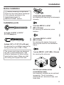
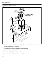
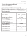
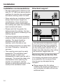
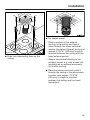
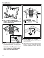
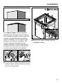
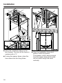
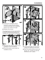
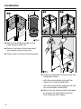
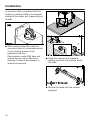
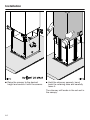
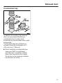
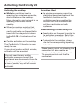
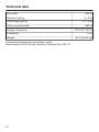
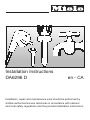
Installation Instructions DA6296 D en - CA Installation, repair and maintenance work should be performed by a Miele authorized service technician in accordance with national and local safety regulations and the provided installation instructions. Installation Before installation Before installing the appliance, read all of the information contained in this chapter and also in the "IMPORTANT SAFETY INSTRUCTIONS" section. 4 extension piece holders for aligning and securing the telescopic chimney Installation parts 4 screws, 6 9/16" x 4 5/16" (7 x 110 mm) and 4 plugs, 3/8" x 3 1/8" (10 x 80 mm) for securing the ventilation hood to the ceiling (not for use in USA / CDN). The screws and plugs are designed for use in solid ceilings only. Use different fasteners for other ceiling construction types. Make sure that the ceiling can support the load. 4 screws M3/16" x 5/16" (M4 x 8.5 mm) for securing the extension piece holders. 14 screws M3/16" x 5/16" (M4 x 8 mm) for securing the spacer frame and securing the hood to the installation frame. 1 screw M3/16" x 5/8" (M4 x 16 mm) for securing the chimney. DUI 32 recirculation kit for recirculation mode (not supplied, available as an optional accessory). The kit includes a directional unit, aluminum hose, and hose clips. 31 Installation Appliance dimensions a Mounting area for the exhaust ducting and power cable. In recirculation mode, only the power cord is required. b Possible height range for appliance in vented mode c Possible height range for appliance in recirculation mode d Alternative installation with spacer frame e Air vent positioned at the top for recirculation 32 Installation f A power cord is required to connect the hood to the socket in the ceiling. With extraction mode flexible ducting is also required. Exhaust connection 6" (150 mm) Distance between cooktop and ventilation hood (S) Provided a larger distance is not given by the manufacturer of the cooktop, follow the minimum safety distances between a cooktop and the bottom of the hood. Please also observe the information contained in the "IMPORTANT SAFETY INSTRUCTIONS" section. Minimum distance S Cooking appliance Miele appliance Non-Miele appliance Electric/Induction cooktop 24" (610 mm) Electric grill, deep fat fryer (electric) 26" (660 mm) Multi-burner gas cooktop ≤ 43,000 BTU/hr (12.6 W), no burner > 15,000 BTU/hr (4.5 kW). 26" (660 mm) 30" (760 mm) Multi-burner gas cooktop ≤ 73,800 BTU/hr (21.6 W), no burner > 16,500 BTU/hr (4.8 kW) 30" (760 mm) Multi-burner gas cooktop > 73,800 BTU/hr (21.6 W), or one of the burners > 16,500 BTU/hr (4.8 kW) Not possible Single-burner gas cooktop ≤ 20,500 BTU/hr (6 kW) 26" (660 mm) 30" (760 mm) Single-burner gas cooktop ≤ 27,600 BTU/hr (8.1 kW) 30" (760 mm) Single-burner gas cooktop > 27,600 BTU/hr (8.1 kW) Not possible 33 Installation Installation recommendations Structural support – We also recommend a distance of at least 25 1/2" (650 mm) above electric cooktops to provide more workspace and easier cooking under the hood. – When selecting an installation height, always take the user height into consideration. Users should have ample space to work comfortably on the cooktop and reach the ventilation hood controls with ease. – Please note that the greater the distance from the cooktop, the less effective the hood is at drawing in the cooking vapors. – To achieve optimal vapor extraction, make sure that the hood covers the cooktop. The hood should be positioned centrally over the cooktop, not to the side or rear. – The cooktop should be no wider than the hood. Preferably, it should be narrower. – The mounting area must be easily accessible. The ventilation hood should be easy to reach and disassemble in case a service call is necessary. This should be taken into consideration when planning the position of cupboards, shelves, ceilings or decorative elements in the vicinity of the ventilation hood. 34 The hood must be attached to rigid structural framing that is supported in its entirety by the ceiling joists, or to the ceiling joists directly. Do not attach the plate directly to the ceiling with anchors, toggle bolts, etc. Removing the protective film The housing components are covered by a protective film to prevent them from becoming damaged during transport. Please remove this film before installing the housing components. It can be peeled off easily without any additional tools. Installation 8 2 5/8 5/8" 8 mm 20 m " 0 m 22 For vented mode: dai3435aus Draw two intersecting lines on the ceiling. – Place a section of the exhaust ducting in the ceiling and feed it down through the cross-sectional area as illustrated. Exhaust ducting of approx. 27 9/16" (700 mm) length is required between the ceiling and the hood exhaust socket. – Secure the exhaust ducting to the exhaust socket, e.g. with a hose clip (available as an optional accessory) on flexible ducting. Place the power cord and guide it through the ceiling in the area shown. A power cord approx. 27 9/16" (700 mm) in length is required between the ceiling and the hood connectors. 35 Installation Use a knife to release the four spacers and the two covers from the spacer frame supplied. Drill four holes 3/8" (10 mm), approx. 4 1/2" (115 mm) deep for the plugs supplied. Use the spacer frame as a drilling template. Place it on the ceiling with the arrows pointing forwards. Using the notches, align the spacer frame on the intersecting lines and make pencil marks for the drill holes. 36 Place the four plugs in the holes and screw in the four screws so that they protrude by approx. 1 3/16" (30 mm). Installation The spacer frame can be installed between the chimney and the ceiling. This creates a shadow which gives the illusion of a gap between the ceiling and the chimney. This is useful if the ceiling is not level or is uneven. The hood is aligned vertically with the spacers supplied. Visual irregularities between the chimney and the ceiling are then concealed by the shadow. Mount the spacer frame onto the installation frame. If you wish to install the hood with the spacer frame, remove the four inserts from the fixing holes. 37 Installation Hang the installation frame on the four screws. The front of the frame is marked with a "V." If using the spacer frame, place the two covers into the fixing holes. 38 Align the installation frame and secure it with the screws. The spacers, which were removed from the spacer frame at the start, can be used to align the hood vertically. Installation Holding the installation frame securely, remove the two fixing screws and extend the installation frame to its maximum length. Replace the screws. The directional unit from recirculation kit DUI 32 (optional accessory) is installed for recirculation mode (RM): Bend the four retaining tabs on the installation frame outwards. Place the power cord inside the installation frame. Fit the directional unit as shown, noting the marking on the front. Bend the retaining tabs back and approx. 45° inwards to hold the directional unit in place. 39 Installation Secure the exhaust socket to the hose using a hose clip. Secure the hose to the directional unit socket using a hose clip. Check that the hose is held securely. Push the telescopic chimney over the installation frame: – with the recirculation grilles at the bottom for vented mode (AE), – with the recirculation grilles at the top for recirculation mode (RM). Bend the two retaining tabs outwards to prevent the telescopic chimney from slipping down again. 40 Installation Fit the four telescopic chimney clamps. When the screws are tightened, the clamps spread out and push the telescopic expansion piece upwards. Bend back the two retaining tabs. Push the chimney over the telescopic chimney and bend the retaining tabs outwards again to prevent the chimney from slipping down again. Tighten the screws only until the top edge of the telescopic chimney is evenly aligned with the ceiling or the spacer frame. 41 Installation A non-return flap is supplied with the hood or is already fitted in the exhaust socket of the motor unit (depending on model). With vented mode (AE) insert the non-return flap in the exhaust socket if your ducting system is not equipped with one. Recirculation mode (RM) does not require the non-return flap to be inserted. If there is one present, it should be removed. Hang the hood on the brackets, making sure that the controls are at the front. Secure the hood with the screws supplied. 42 Installation Connect the power cord. See "Electrical connection." Unscrew both screws from the installation frame again. Place the exhaust ducting onto the exhaust socket. The canopy can now be adjusted to the desired height, observing the permissible height ranges: – With vented mode: upwards as far as it will go, downwards only to the "A" marking. – With recirculation mode: upwards as far as the "U", downwards as far as it will go. Follow the instructions in "Appliance dimensions." Safety distances between the cooktop and ventilation hood must be observed. 43 Installation Raise the canopy to the desired height and secure it with the screws. Hold the chimney securely, bend back the retaining tabs and carefully lower it. The chimney will locate in the cut-out in the canopy. 44 Installation With recirculation mode (RM) ventilation hoods, insert the OdorFree Charcoal Filter. Remove the grease filters from the hood. Insert the safety screw on the inside. Carefully remove the protective foil from the grease filters. Reinsert the grease filters. 45 Exhaust duct WARNING: Danger of toxic fumes. Gas cooking appliances release carbon monoxide that can be harmful or fatal if inhaled. To reduce the risk of fire and to properly exhaust air, the exhaust gases extracted by the hood should be vented outside of the building only. Do not vent exhaust air into spaces within walls or ceilings or in attics, crawl spaces or garages. To reduce the risk of fire, only use metal ductwork. Please read and follow the "IMPORTANT SAFETY INSTRUCTIONS" to reduce the risk of personal injury. Follow all local building codes when installing the hood. Only use smooth pipes or flexible duct hoses made from nonflammable materials for exhaust ductwork. To achieve the greatest possible air extraction with the lowest noise levels, please note the following: – The diameter of the exhaust duct should not be less than 6" (150 mm). – If flat exhaust ducts are used, the cross section should not be smaller than that of the exhaust connector. – The exhaust duct should be as short and straight as possible. – If elbows are needed, make sure they have a large radius. – The exhaust duct itself must not be kinked or compressed. 46 – Make sure that all connections are secure and airtight. Remember that any constriction of the airflow will reduce extraction performance and increase operating noise. If the exhaust duct is to be routed through an outside wall, we recommend installing a telescopic wall vent or a rooftop vent (available as an optional accessory). If the exhaust air is to be conducted into a vent flue, the intake piece must be aligned with the flow direction of the flue. When installing the exhaust duct horizontally, you must slope it away from the source by at least 1 cm per meter (3/8" per 3 1/4'). This ensures that condensate cannot drain back into the ventilation hood. If the exhaust duct is to be routed through rooms, ceiling space etc., the temperatures in these different areas may differ greatly, which means that the problem of condensation will need to be addressed. The exhaust duct will need to be insulated. Exhaust duct Condensate trap In addition to insulating the exhaust duct, we recommend installing a condensate trap to collect and evaporate any condensate which might accumulate. Condensate traps are available for exhaust ducts with a diameter of 5" (125 mm) or 6" (150 mm). When installing a condensate trap, make sure that it is positioned vertically and, if possible, directly above the hood outlet duct collar. The arrow on the housing indicates the direction of airflow. 47 Electrical connection WARNING: TO REDUCE THE RISK OF FIRE, ELECTRIC SHOCK, OR INJURY TO PERSONS, OBSERVE THE FOLLOWING: All electrical work should be performed by a qualified electrician in strict accordance with national regulations (for USA: ANSI-NFPA 70) and local safety regulations. Installation, repairs and other work by unqualified persons could be dangerous. Ensure that power to the appliance is OFF while installation or repair work is performed. Verify that the voltage, load and circuit rating information found on the data plate (located behind the baffle filters), match the household electrical supply before installing the hood. Use only with ventilation hood cordconnection kits that have been investigated and found acceptable for use with this model hood. If there is any question concerning the electrical connection of this appliance to your power supply, please consult a licensed electrician or call Miele’s Technical Service Department. WARNING: THIS APPLIANCE MUST BE GROUNDED 48 Grounding Instructions WARNING - Improper grounding can result in a risk of electric shock. This appliance must be grounded. In the event of an electrical short circuit, grounding reduces the risk of electric shock by providing a path of least resistance.plug. If there is any doubt, have the electrical system of the house checked by a qualified electrician. To increase security before the machine is installed, it is recommended to install a protective switch(30mA). The hood must be hard wired accordingly: Black/Red wire: connect to L1 (live) White wire: connect to N (neutral) Green wire: connect to GND (ground) Activating Con@ctivity 2.0 Installation of the Con@ctivity 2.0 stick In order for you to be able to use the Con@ctivity 2.0 function, the cooktop must be equipped with a Con@ctivity 2.0 stick. See the relevant installation instructions of the Con@ctivity 2.0 stick. Activating the ventilation hood The cooktop and hood must be switched off. Press the delayed shut-down button 515 for approx. 10 seconds until the 1 indicator appears in the fan level display. Then, press the following buttons in order: Activating the Con@ctivity 2.0 function – The "" button, To use the Con@ctivity 2.0 function, the radio link between the cooktop and the ventilation hood must be activated. – And then the lighting button . Both appliances must be installed and operational. Wireless connection must be activated on the ventilation hood and the cooktop at the same time. Activation on the ventilation hood is described below. Activation on the cooktop is described in the relevant operating and installation instructions. Please refer to the operating instructions before starting. Activate the ventilation hood first, then the cooktop. – Followed by the "" button, The hood is in log on / log off mode. If the wireless connection is already activated, 2 and 3 will light up at the same time. If there is no wireless connection, 2 and 3 will flash constantly (Con@ctivity 2.0 is already activated or a remote control is logged on). To activate Con@ctivity 2.0, press the "" button. The search for a wireless connection will start. As this is happening, begin activation on the cooktop. 49 Activating Con@ctivity 2.0 Activating the cooktop Activation failed While the ventilation hood is searching for a wireless connection, start activation on the cooktop. More information can be found in the operating instructions for the cooktop. If a wireless connection cannot be established despite activation of the Con@ctivity function on the ventilation hood and cooktop, the function must first be deactivated and then reactivated on both appliances. When the cooktop registers that connection has been established, confirm activation on the ventilation hood with the delayed shut-down button 515. All indicators will go out. Confirm activation on the cooktop. The Con@ctivity 2.0 function is now ready for use. If you do not confirm within 4 minutes, activation will be canceled. You only need to carry out the activation procedure once. If the appliances are disconnected from the electricity supply, for example during a loss of power, they will still remain activated. 50 Deactivating Con@ctivity 2.0 Deactivation on the hood is similar to the activation procedure. Select the "" button instead of the "" button. To deactivate the cooktop, please refer to the corresponding operating instructions. Please keep in mind that disabling the connection will also disable any remote control function being used. The remote control must then be reactivated. Service and warranty For faults that you cannot resolve on your own, please contact your Miele dealer or Miele Technical Service. The telephone number for the Technical Service Department is listed at the back of these instructions. When contacting Miele, please state the model and serial number of your ventilation hood. These can be found on the data plate. Location of the data plate The data plate is visible once you have removed the grease filters. Warranty For further information, please refer to your warranty booklet. 51 Technical data Fan motor Cooktop lighting Glass edge lighting Total connected load Voltage, Frequency Fuse rating Weight Optional accessories for recirculation mode: Recirculation kit DUI 32 and OdorFree Charcoal Filter DKF 12 52 350 W 4x3W 2 x 10 W 382 W 120 V AC, 60 Hz 15 A 81.4 lbs (37 kg) Please have the model and serial number of your appliance available before contacting Technical Service. U.S.A. Canada Miele, Inc. Importer Miele Limited National Headquarters 9 Independence Way Princeton, NJ 08540 Phone: 800-843-7231 609-419-9898 609-419-4298 Fax: www.mieleusa.com Technical Service & Support Nationwide Phone: 800-999-1360 888-586-8056 Fax: [email protected] Headquarters and Miele Centre 161 Four Valley Drive Vaughan, ON L4K 4V8 www.miele.ca Customer Care Centre Phone: 800-565-6435 905-532-2272 [email protected] Germany Manufacturer Miele & Cie. KG Carl-Miele-Straße 29 33332 Gütersloh 53 DA 6296 D en-US M.-Nr. 09 968 600 / 00