1
Operator's
Manual
I:RI:IFI"$MI:IN
17-Inch Straight Shaft/31 cc/2-Cycle
GAS-POWERED WEEDWACKER ®
LINE TRIMMER
Model No.
316.74556
•
•
•
•
•
•
manual and follow all its Safety Rules and
,_WARNING:
Before using this product, read this
Operating Instructions.
Sears, Roebuck,
and Co., Hoffman
OPERATOR'S MANUAL PART NO. 769-00067
PRINTED IN U.S.A.
Safety
Assembly
Operation
Maintenance
Parts List
Espa_ol
Save this manual for future reference,
Estates,
IL 60179 USA
2/02
Revl
2
Limited Warranty Statement
California Proposition 65 Warning
2
2
3
7
8
10
Spark Arrestor
Rules for Safe Operation
Contents of Hardware Pack
Assembly
Operation
FULL ONE-YEAR
WARRANTY
ON CRAFTSMAN®
Maintenance
14
Service and Adjustments
Storage
Specifications
Troubleshooting Chart
EPA
Parts List
Espa_ol
16
19
20
21
22
23
E1
GAS-POWERED
WEEDWACKER®
TRIMMER
For one year from the date of purchase, when this Craftsman Gas-Powered Weedwacker Trimmer is maintained, lubricated
and tuned up according to the operating and maintenance instructions in the operator's manual, Sears will repair, free of
charge, any defect in materials or workmanship.
This warranty excludes nylon line, spark plug, and air filter, cutting head, Bump Knob, and expendable parts that become
worn during normal use.
If this Weedwacker Trimmer is used for commercial purposes, this warranty applies for 90 days from the date of purchase.
If this Weedwacker Trimmer is used for rental purposes, this warranty applies for 30 days from the date of purchase.
This warranty applies only while this product is in use in the United States.
WARRANTY SERVICE IS AVAILABLE BY RETURNING THE WEEDWACKER TRIMMER TO THE NEAREST SEARS SERVICE
CENTER iN THE UNITED STATES.
This warranty gives you specific legal rights, and you may also have other rights which vary from state to state.
Sears, Roebuck
and Co., D/817 WA, Hoffman
Estates, IL 60179
THE ENGINE EXHAUST FROM THIS
PRODUCT CONTAINS CHEMICALS
KNOWN TO THE STATE OF CALIFORNIA
TO CAUSE CANCER, BIRTH
OR OTHER REPRODUCTIVE
DEFECTS
HARM.
NOTE: For users on U.S. Forest Land and in the states of California, Maine, Oregon and Washington. All U.S.
Forest Land and the state of California (Public Resources Codes 4442 and 4443), Oregon and Washington require by law
that certain internal combustion engines operated on forest brush and/or grass-covered areas be equipped with a spark
arrestor, maintained in effective working order, or the engine be constructed, equipped and maintained for the prevention
of fire. Check with your state or local authorities for regulations pertaining to these requirements. Failure to follow these
requirements could subject you to liability or a fine. This unit is factory equipped with a spark arrestor. If it requires
replacement, ask your Sears Service Center to install the Accessory Part #182747 Spark Arrestor.
SPECIAL NOTE: Exposure to vibrations through prolonged use of gasoline powered hand tools could cause blood vessel
or nerve damage in the fingers, hands, and joints of people prone to circulation disorders or abnormal swelling.
Prolonged use in cold weather has been linked to blood vessel damage in otherwise healthy people, if symptoms occur
such as numbness, pain, loss of strength, change in skin color or texture, or loss of feeling in the fingers, hands or joints,
discontinue use of this tool and seek medical attention. An anti-vibration system does not guarantee the avoidance of
these problems. Users who operate power tools on a continual and regular basis must monitor closely their physical
condition and the condition of this tool
-2-
The purpose of safety symbols is to attract your
attention to possible dangers. The safety symbols, and
their explanations, deserve your careful attention and
understanding. The safety warnings do not by
themselves eliminate any danger. The instructions or
warnings they give are not substitutes for proper
accident prevention measures.
SYMBOL
MEANING
I,_
_b
SAFETY ALERT SYMBOL: Indicates
danger, warning, or caution. Attention is
required in order to avoid serious personal
injury. May be used in conjunction with other
symbols or _hs.
NOTE: Advises you of information or instructions vital
to the operation or maintenance of the equipment.
• IMPORTANT
READ ALL INSTRUCTIONS
BEFORE
,_
will result in serious injury to yourself or to
others. Always follow the safety precautions
to reduce the risk of fire, electric shock, and
ANGER: injury.
Failure to obey a safety warning
personal
ARNING: Failure to obey a safety warning
can result in injury to yourself and others.
Always follow the safety precautions to
reduce the risk of fire, electric shock, and
personal injury.
may result in property damage or personal
injury to yourself or to others. Always follow
the
safety precautions
to reduce
thewarning
risk of
CAUTION:
Failure to obey
a safety
fire, electric shock, and personal injury.
SAFETY INFORMATION
OPERATING
SAFETY
WARNINGS
•
FOR GAS TRIMMERS
• Read the instructions carefully. Be familiar with the
controls and 3roper use of the unit.
WARNING: Gasoline is highly flammable, and its vapors
can explode if ignited. Take the following precautions:
• Do not operate this unit when tired, ill. or under the
influence of alcohol, drugs, or medication.
• Store fuel only in containers specifically designed and
approved for the storage of such materials,
• Children and teens under the age of 15 must not use
the unit. except for teens guided by an adult.
• Avoid creating a source of ignition for spilled fuel. Do
not start the engine until fue! vapors dissipate.
• Inspect the unit before use. Replace damaged parts.
Check for fuel leaks. Make sure all fasteners are in place
and secure. Replace cutting attachment parts that are
cracked, chipped, or damaged in any way. Make sure
the cutting attachment is properly installed and securely
fastened. Be sure the cutting attachment shield is
properly attached, and positioned as recommended.
Failure to so can result in personal injury to the operator
and bystanders, as well as damage to the unit
, Always stop the engine and allow it to cool before filling
the fuel tank. Never remove the cap of the fuel tank, or
add fuel, when the engine is hot, Never operate the unit
without the fuel cap securely in place. Loosen the fuel
tank cap slowly to relieve any pressure in the tank.
• Be aware of the risk of injury to the head. hands end feet.
• Mix and add fuel in a clean, well-ventilated area
outdoors where there are no sparks or flames. Slowly
remove the fuel cap only after stopping engine. Do
not smoke while fueling or mixing fuel wipe UP any
spilled fuel from the unit immediately.
• Use only 0.080 in (2.03 mm) diameter genuine
Craftsman® replacement line. Never use metal-reinforced
line. wire. or rooe. etc. These can break off and become
dangerous projectiles.
• Move the unit at least 30 ft. (9.1 m) from the fueling
source and site before starting the engine. Do not
smoke, keep sparks and open flames from the area
while adding fuel or operating the unit.
• Clear the area to be cut before each use. Remove al
objects such as rocks, broken glass, nails, wire. or
string which can be thrown or become entangled in
the cutting attachment.
WHILE
OPERATING
• Never start or run the unit inside a closed room or
building. Breathing exhaust fumes can kill. Operate
this unit on!Y in a well ventilated area outdoors.
• Clear the area of children, bystanders and pets. At a
minimum keep all children, bystanders end pets outside a
50 ft. (15 m.) radius: there still may be a risk to bystanders
from thrown objects. Encourage bystanders to wear eye
protection. If you are approached, stop the engine end
cutting attachment immediately.
• Wear safety glasses or goggles that are marked as
meeting ANSI Z87.1-1989 standards, and ear/hearing
protection when operating this unit. Wear a face or dust
mask if the operation is dusty. Long sleeve shirts are
recommended.
• Wear heavy, long pants, boots and gloves. Do not
wear loose clothing, jewelry, short pants, sandals, or
go barefoot, Secure hair above shoulder level.
• Squeeze the throttle control end check that it returns
automatically to the neutral position. Make all adjustments
or repairs before using unit.
• Adjust the assist handle to your size to provide the
best grip.
• This unit was not designed to be used as a brushcutter. Do
net attach or operate this unit with any type of brushcutting
blade or brushcutting attachment.
-3-
•
Be sure the cutting attachment is not in contact with
anything 3efore starting the unit.
• Stop and switch the engine to off for maintenance,
repair, or for changing the cutting attachment or other
attachments.
• The cutting attachment shield must always be in place
while operating the unit as a tnmmer. Do not operate
unit without both trimming lines extended, and the
proper line installed. Do not extend the trimming line
beyond the length of the shield.
• Use only genuine Craftsman® replacement parts when
servicing this unit. These parts are available from your
authorized service dealer. Do not use parts, accessories
or attachments not authorized by Craftsman for this
unit. Doing so could lead to serious injury to the user, or
damage to the unit, and void your warranty.
• This unit has a clutch. The cutting attachment will not
rotate when the engine is idling. Engine adjustments
should be done by any nonroad engine repair
establishment, individual or authorized service deale_
• Keep unit clean of vegetation and other materials.
They may become lodged between the cutting
attachment and shield.
• Use the unit only in daylight or good artificial light.
• To reduce fire hazard, replace faulty muffler and spark
arrestor, keep the engine and muffler free from grass,
leaves, excessive grease or carbon build up.
• Avoid accidental starting. Be in the starting position
whenever pulling the starter rooe. The operator ant
unit must be in a stable position while starting. See
Stopping/Starting
InstracUons in the Operation
section.
OTHER
SAFETY
WARNINGS
• Never store the unit, with fuel in the tank, inside a
building where fumes may reach an open flame or spark.
• Use the right tool for the job, and use this tool only for
the purpose intended.
• Allow the engine to cool before storing or transporting.
B e sure to secure th e unit while transporting.
• Do not overreach. Always keep proper footing and
balance.
• Store the unit in a locked up and dry, or high and dry
place to prevent unauthorized use or damage, Keep
out of the reach of children.
• Always hold the unit with both hands when operating.
Keep a firm grip on both the front and rear handle or grips.
• Keep hands, face and feet at a distance from all
moving parts. Do not touch or try to stop the cutting
attachment when it is rotating.
• Never douse or squirt the unit with water or any other
liquid. Keep handles dry, clean and free from debds. Clean
after each use. See the Maintenance and Storage
sections.
• Do not touch the engine or muffler. These parts get
extremely hot from operation. When turned off they
remain hot for a short time.
• Keep these instructions. Refer to them often and use
them to instruct other users. If you loan someone this
unit, also loan them these instructions.
• Do not operate the engine faster than the speed
needed to cut. trim or edge. Do not run the engine at
high speed when not cutting.
SAVE THESE
• Always stop the engine when cutting is delayed or
when walking from one cutting location to another.
• If you strike or become entangled with a foreign
object, stop the engine immediately and check for
damage. Do not operate before repairing damage. Do
not operate the unit with loose or damaged parts.
-4-
INSTRUCTIONS
SAFETY
AND INTERNATIONAL
SYMBOLS
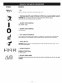
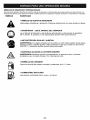
This operator's manual describes safety and international symbols and pictographs that may appear on this product.
Read the operator's manual for complete safety, assembly, operating and maintenance and repair information.
SYMBOL
MEANING
• SAFETY
ALERT
SYMBOL
Indicates danger, warning, or caution. May be used in conjunction
symbols or pictographs.
• WARNING
- READ OPERATOR'S
with other
MANUAL
Read the Operator's Manual(s) and follow all warnings and safety instructions.
Failure to do so can result in serious injury to the operator and/or bystanders.
• WEAR
EYE AND HEARING
PROTECTION
WARNING: Thrown objects and loud noise can cause severe eye injury and hearing loss.
Wear eye protection meeting ANSI Z87.1 standards and ear protection when operating
this unit. Use a full face shield when needed.
• KEEP BYSTANDERS
AWAY
WARNING: Keep all bystanders, especially children and pets, at least 50 feet (15 m)
from the operating area.
5"7x
• PRIMER
BULB
Push primer bulb, fully and slowly, 5 to 7 times.
• UNLEADED
FUEL
Always use clean, fresh unleaded fuel.
-5-
SYMBOL
MEANING
• OIL
Refer to operator's
• THROWN
manual for the proper type of oil.
OBJECTS
AND ROTATING
CUTTER
CAN CAUSE SEVERE
WARNING: Do not operate without the cutting attachment
Keep away from the rotating cutting attachment.
• ON/OFF
STOP
INJURY
shield in place.
CONTROL
ON / START / RUN
• ON/OFF
STOP
CONTROL
OFF OR STOP
• HOT SURFACE
WARNING
Do not touch a hot muffler, gear housing or cylinder. You may get burned. These parts
get extremely hot from operation. When turned off they remain hot for a short time.
• SHARP
BLADE
WARNING: Sharp blade on cutting attachment shield. To prevent serious injury, do not
touch line cutting blade.
A
H
B
C
• CHOKE
CONTROL
A: FULL choke position.
B: PARTIAL choke position.
C: RUN position.
• DO NOT USE BLADES
WARNING: To prevent serious injury, do not attach or operate the unit with any type
of blade.
-6-
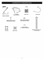
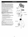
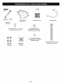
17" Cutting
Attachment Shield
Bottle of Oil
Assist Handle
Operator's Manual
(3) Screws (10-24 x 1/2) - for
Cutting Attachment Shield
(3) Hex Lock Nuts (#10-24) for
Cutting Attachment Shield
(4) Hex Jam Nuts (1/4 x 20) for Assist Handle
Top Clamp
(4) Screws (1/4-20 x 2-1/4")
- for Assist Handle
Middle Clamp
-7-
CARTON
CONTENTS
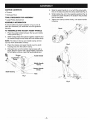
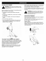
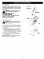
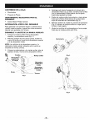
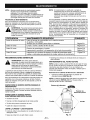
5.
Slide the assist handle in or out until the arrow/white
line on the decal touches the c!am p assembly (Fig, 2).
6, While holding the unit in the operating position (Fig. 3),
position the assist handle to the location that provides
you the best grip:
• Trimmer
• Hardware Pack
TOOLS
REQUIRED
FOR ASSEMBLY
7. Tighten the clamp screws evenly, until assist handle
is secure.
• Large Phillips Screwdriver
ASSEMBLY
INFORMATION
To ensure safe and proper operation of your unit, all
parts and hardware you assemble must be tightened
securely.
TO ASSEMBLE
AND ADJUST
ASSIST
Decal
HANDLE
1. Place the assist handle between the top and middle
clamp pieces (Fig. 1).
2.
/
While holding these three pieces together, install the four
(4) screws through the top clamp and into middle clamp.
NOTE: The holes in the top and middle clamp will line
up only when assembled correctly.
3.
Place the clamps and assist handle over the shaft
housing and onto the bottom clamp.
4.
Hold each hex nut in the bottom clamp recess with a
finger. Start the screws with a large Phillips screwdriver.
Do not tighten until you make the handle adjustment.
Fig. 2
Assist Handle
Middle Handle
C,amp
J Bottom Handle
Clamp
Shaft Housing
-,
Nuts
Fig. 1
Fig. 3
-8-
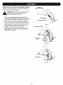
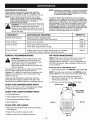
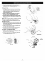
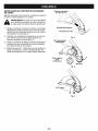
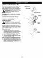
INSTALLING
THECUTTINGATTACHMENTSHIELD
Cutting
Attachment
Shield
Use the following instructions if the cutting attachment
shield on your unit is not installed.
_b
theARNING:
cutting attachment
shield
place towithout
Never operate
the intrimmer
prevent serious personal injury.
1. Slide the cutting attachment shield into the shield
mount on the cutting attachment. Align the screw holes
in the shield with the holes in the shield mount (Fig. 4).
2. Place a hex lock nut into one of the three recessed
holes on the top of the cutting attachment shield (Fig 5).
3.
Install a screw into the hole from the bottom of the
cutting attachment shield and screw it into the nut
installed in step #2 (Fig 6). Do not tighten.
4.
Repeat steps 2 and 3 until all three screws have
been started, then tighten screws securely with an
appropriate screwdriver.
Shield Mount
Cutting
Attachment
Fig. 4
(3) Hex Lock Nuts
Top of Lock
Nut
_lndents
Fig. 5
(3)
Fig. 6
-9-
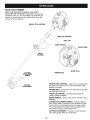
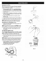
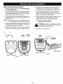
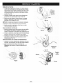
KNOW
YOUR
TRIMMER
READ THIS OPERATOR'S MANUAL AND SAFETY
RULES BEFORE OPERATING YOUR UNIT. Compare the
illustrations with your unit to familiarize yourself with the
location of various controls and adjustments. Save this
manual for future reference.
ON/OFF STOP CONTROL
THROTTLECONTROL
FUEL CAP
'\
--
ASSIST HANDLE
CHOKE LEVER
SHAFT
HOUSING
l/
SPARK PLUG
PRIMER BULB
CUTTING
ATTACHMENT
SHIELD
ON/OFF STOP CONTROL - used to turn the engine ON
and OFE The switch must be in the ON position when
starting the engine.
CUTTING
ATTACHMENT
PRIMER BULB - removes air from the fuel lines and fills
the carburetor with fuel.
THROTTLE CONTROL - controls engine speed for
various cutting conditions.
ASSIST HANDLE - used to hold the line trimmer during
operation.
CUTTING ATTACHMENT SHIELD - protects operator
from thrown debris. Contains line cut-off blade to make
sure the line is not extended beyond its proper length.
The cutting attachment shield must be installed at all
times when using the cutting attachment.
CUTTING ATTACHMENT - consists of a reel housing,
reel, spring, Bump Knob and cutting line.
-10-
THIS ENGINE
IS CERTIFIED
TO OPERATE
ON UNLEADED
TO FUEL ENGINE
tf you choose to use a blended fuel, or if its use is unavoidable I the following precautions are recommended.
CAUTION: Be sure to read these instructions
carefully before attempting to start or operate
this unit. Using old or _mproper oil or fuel. or
improperly mixing the oil and fuel. can cause
engine damage. This type of damage will VOID
the engine warranty.
1. Always
3. Always agitate the fuel mix before fueling the unit,
4. Drain the tank and run the engine dry before storing
the unit.
tf using a brand of oil other than Craftsman, use of fuel
stabilizer will inhibit corrosion and minimize the
formation of gum deposit. Add 0.8 oz. (23 ml) of
stabilizer per gallon of fuel per instructions on container.
NEVER add fuel stabilizer directly to the unit's fuel tank.
Using a fuel stabilizer can keep fuel fresh for up to six
(6) months.
Oil Type
A 3.2 oz. (95ml) bottle of Craftsman® 2-cycle engine oil.
containing fuel stabilizer, is included with your product.
Craftsman brand oil is recommended for this outdoor
power tooL. f another brand is used. make sure it is high
quality oil. formulated for 2-cycle. air-cooled engines.
CAUTION:
,_
DANGER: Combustible mixture contains
petroleum distillate. Store away from heat or
open flame. Harmful or fatal if swallowed. If
swallowed, do not induce vomiting. CALL
PHYSICIAN IMMEDIATELY. Avoid prolonged
contact with skin. Wash thoroughly after
handling. Do not reuse bottle.
Recommended
use fresh fuel mix:
2. Use a specia! additive.
WARNING: Gasoline is extremely flammable
and its vapors can explode if they are ignited.
Always stop the engine and allow it to cool
before filling the fuel tank. Do not smoke while
filling the tank. Keep sparks and open flames
away from the area.
Recommended
GAS AND OIL MIXTURE,
Fuel Type
For proper engine operation and
oil and fuel mixing instructions on the 2-cycle
maximum reliability, pay strict attention to the
oil container. Use a 40:1 fuel/oil ratio. Use 2cycle oil. Using improperly mixed fuel can
severely damage the engine.
UNLEADED GAS
Use clean, fresh, unleaded gasoline that is less than 60
days old.
1 US, GALLON
Oil and Fuel Mixing Instructions
SEARS 2 CYCLE OIL
+
(95ml)
(3,8 LITERS)
Thoroughly mix the proper ratio of unleaded gasoline
with 2-cycle engine oil in a separate fuel can. 40:1. Do
not mix them directly in the engine fuel tank.
1 LITER
MIXING
Use 3.2 oz. (95ml) of 2-cycle engine oil per one gallon of
unleaded gasoline to achieve a 40:1 fuel/oil ratio.
Use of Blended Fuels
-11
-
3,2 FL, OZ,
+
25 ml
RATIO - 40:1
IMPORTANT
Experience indicates that alcohol blended fuels (called
gasohol or using ethanol or methanol) can attract moisture
which leads to separation and formation of acids during
storage. Acidic gas can damage the fuel system of an
engine while in storage. To avoid engine problems, empty
the fuel system before storage of 30 days or longer. Drain
the fuel tank, start the engine and let it run until the fuel
lines and carburetor are empty. Use fresh fuel next season.
On/Off Stop
Control
Never use engine or carburetor cleaner products in the
fuel tank or permanent damage may occur.
Fig. 7
See the Storage section for additional information.
STOPPING
INSTRUCTIONS
1. To stop the engine move On/Off Stop Control to OFF (Fig. 7).
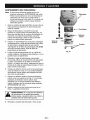
STARTING
INSTRUCTIONS
NOTE; Mix gas with oil (40:1 ratio). See Oil and Fuel
Mixing Instructions
in the Operation section. Fill your
unit with oil and gas mixture and set it on the ground to
start (Fig. 9).
1. Move On/Off Stop Control to ON (Fig. 7).
2.
Fully press and release primer bulb slowly 5 to 7 times. Fuel
should be visible in the bulb (Fig. 8). If fuel hasn't entered the
bulb, press three (3) more times, or until it does.
3.
Move choke lever (Fig. 8) to CHOKE
4.
Squeeze throttle control and pull starer rope (Fig. 9) until
engine attempts to start (5 pulls maximum).
5.
Move choke to
6.
Pull starter rope (Fig. 9) until engine starts (3 pulls maximum).
7.
if engine does not star within 3 pulls, repeat steps 2-6.
Primer Bulb
(H A).
Fig. 8
(N B).
8. Allow engine to run 10 seconds, then move choke to
RUN(IH C).
Starter Rope
NOTE; For a warm engine, go directly to Step 5 above.
Move choke to (l'q B). Be sure the On/Off Stop Control
is in the ON position.
NOTE; if the engine floods while trying to start, place the
choke lever in the RUN (C) 141position (Fig. 8). Squeeze
the throttle control. Pull the starter rope briskly. The
engine should start within three (3) to eight (8) pulls.
Throttle
Fig. 9
-12-
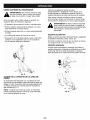
HOLDING
,_
THE TRIMMER
Each time the head is bumped, about 1 in. (25.4 mm) of
line is released. A blade in the guard will cut the line to
the proper length if excess line is released.
body protection to reduce the risk of injury when
WARNING: Always wear eye, hearing, foot and
operating this unit.
For best results, bump the head on bare ground or hard
soil. If line release is attempted in tall grass, the engine
may stall.
Before operating the unit, stand in the operating position
(Fig. 10). Check for the following:
WARNING: Do not remove or alter the line
cutting blade assembly. Excessive line length
can cause clutch to overheat and result in
serious personal injury.
• The operator is wearing eye protection and proper
clothing.
• The right arm is slightly bent, and the hand is holding
the shaft grip.
DECORATIVE
• The left arm is straight, and the hand is holding the
handle.
TRIMMING
Perform decorative trimming by removing all vegetation
around trees, posts, fences, etc.
• The unit is below waist level.
Rotate the entire unit so that the cutting attachment
at a 30 ° angle to the ground (Fig. 12).
• The cutting attachment is parallel to the ground and
easily contacts the vegitation to be cut without the
operator having to bend over.
Proper
stance
When operating the unit, maintain proper footing and
balance. Hold the unit with both hands (Fig. 10). Do not
overreach. Keep all parts of your body away from the
cutting attachment.
Fig. 11
TO ADJUST
Fig. 10
THE TRIMMING
is
LINE LENGTH
Your trimmer is equipped with a cutting attachment that
allows the operator to release more trimming line without
stopping the engine. To release additional line, lightly
bump the cutting attachment on the ground while
operating the trimmer at high speed (Fig. 11).
\\
Fig. 12
NOTE: Line release becomes more difficult as cutting
line becomes shorter. Always keep the trimming line
extended to its full cutting length.
-13-
MAINTENANCE
SCHEDULE
NOTE: Maintenance, replacement, or repair of the emission
control devices and system may be performed by
any nonroed engine repair establishment, individual
or authorized service dealer.
These required maintenance procedures should be
performed at the frequency stated in the table. They
should also be included as part of any seasonal tune-up.
NOTE: Some maintenance procedures may require
special tools or skills. If you are unsure about
these procedures take your unit to any nonroad
engine repair establishment, individual or
authorized service dealer.
i_
In order to assure peak performance of your engine,
inspection of the engine exhaust port may be necessary
after 50 hours of operation. If you notice lost RPM, poor
performance or general lack of acceleration, this service
may be required. If you feel your engine is need of this
inspection, refer service to any nonroad engine repair
establishment, individual or authorized service dealer for
repair. DO NOT attempt to perform this process yourself
as engine damage may result from contaminants
involved in the cleaning process for the port.
maintenance or repairs with unit running.
Always do maintenance and repairs on a cool
Disconnect
spark plug
wireinjury,
to ensure
_b unit.
WARNING:
T° prevent
seri°us
never the
do 1
unit will not start.
I
FREQUENCY
MAINTENANCE
Before Starting Engine
Check for loose or damaged parts.
Fill fuel tank with correct oil and fuel mixture.
Page 11
Every 10 Hours
Clean and re-oil air filter.
Page 14
Every 25 Hours
Check spark arrestor and clean.
Check spark plug condition and gap.
Page 18
Page 15
Every 50 Hours
Inspect exhaust port and spark arrestor screen for clogging
or obstruction to assure maximum performance levels.
Page 18
_ENERAL
REQUIRED
RECOMMENDATIONS
AIR FILTER MAINTENANCE
NOTE: Clean and re-oil the air filter every 10 hours of
operation. Your unit's air filter is one of the most
important areas to maintain. If it is not maintained, you
will VOID the warranty. Before cleaning, make sure the
unit is turned off.
perform
maintenance
on serious
the unit injury,
while never
it is
ARNING:
To orevent
running. Shut off the unit and allow it to cool
down before doing any maintenance.
Disconnect the spark plug wire to prevent the
unit from starting.
The warranty on this line trimmer does not cover items
that have been subjected to operator abuse or
negligence. To receive full value from the warranty, the
operator must maintain the unit as instructed in this
operator's manual.
_lJ
Removing the Air Filter/Muffler
!,
FOR DAMAGED/WORN
Cover
Place the choke lever in the PARTIA L choke Position (B).
NOTE: The choke lever must be in the PARTIAL choke
position (B) (Fig. 13) to remove the air filter/muffler cover.
2. Remove the four (4) screws securing the air
filter/muffler cover (Fig. 13), Use a flat blade or
"1"-20Torx bit screwdriver.
These required maintenance procedures should be
performed at the frequency stated in the table. They
should also be included as part of any seasonal tune-up.
CHECK
REFER TO:
3- Pull the cover from the engine. Do not force.
PARTS
Choke
1
Lever
Inspect the unit for any worn or damaged parts. Repair
or replace damaged parts before operating.
CHECK
FOR LOOSE FASTENER
PARTS
Partial Choke
Position (B)
O
• Cutting Attachment
• Assist Handle Hex Nuts/Screws
• Cutting Attachment
Shield Screws
Screws
• Spark Plug Wire
CLEAN
UNIT AND LABELS
• Clean the unit and labels using a damp cloth with a
mild detergent.
L
i
i
L
i
i
I
I
i
i
/
i
i
\
• Wipe off the unit with a clean dry cloth.
• Keep air vents free from debris at all times.
Fig. 13
-14-
I
/
Cleaning
the Air Filter
Clean and re-oil the air filter every 10 hours of operation.
It is an important item to maintain. Not maintaining the
air filter will VOID the warranty.
1. Remove air filter/muffler cover. See Removing the
Air filter/Muffler Cover in the Maintenance section,
2.
Remove the air filter from behind the air filter/muffler
cover (Fig. 14).
3.
Wash the filter in detergent and water (Fig. 15). Rinse
the filter thoroughly. Squeeze out excess water. Allow
it to dry completely.
4.
Apply enough clean SAE 30 oil to lightly coat the
filter (Fig. 16).
5.
Squeeze the filter to spread and remove excess oil (Fig. 17).
6.
Replace the air filter in the air filter/muffler cover tFig. 14).
Fig. 15
NOTE: Operating the unit without the air filter and air
filter/muffler cover assembly, will VOID the warranty.
Reinstalling the Air filter/Muffler
Cover
1. Place the air filter/muffler cover over the back of the
carburetor and muffler.
NOTE: The choke lever must be in the PARTIAL choke
position (B) (Fig. 13) to install the air filter/muffler cover.
2.
Fig. 16
Insert the four {4) screws into the holes in the air
filter/muffler cover (Fig. 13) ant tighten. Do nol
over tighten.
TO REPLACE
SPARK
PLUG
Use a Champion RDJ7Y spark plug (or equivalent). Correct
a=rgap is 0,020 in, (0,50 mm), Remove plug after every 25
hours of operation and check its condition (Fig. 18).
1.
Stop the engine and pull the wire off of the spark plug.
2.
Clean around the spark plug and remove it from the
cylinder head.
Fig. 17
NOTE: Replace a cracked, fouled or dirty spark plug. Do
not sand blast, scrape or clean electrodes because the
engine could be damaged by grit entering the cylinder.
3.
Set the air gap at 0.020 in. (0.50 ram) using a wire
feeler gauge (Fig. 18). nstall a correctly gapped
spark plug into the cylinder head. Torque to
110-120 inolb (12.3-13,5 Nom).
4.
Replace the spark plug w=re.
0.020
.mj
"
Fig. 18
Air Filter
Fig. 14
-15-
TO CLEAN
UNIT
Do not use any strong detergents on the plastic housing or
the handle. They can be damaged by certain household
cleaners that contain aromatic oils such as pine and lemon,
and by solvents such as kerosene. Wipe off any moisture
with a soft cloth.
_
\
Bump Knob
Captured Bolt
before
servicing
the cutting
ARNING:
To prevent
injury,attachment.
turn the unit off
Reel Housing
LINE INSTALLATION
FOR THE
CUTTING ATTACHMENT
Fig. 19
The trimming line in the cutting attachment may be
replaced by two different methods:
Reel Housing
• Winding the reel with new line, or
Spring
• Installing a prewound reel
/('1
The Correct Line to Use
,_
replacement
line. Touse
avoid
injury do not
use
WARNING: Always
Craftsman®
trimmer
metal reinforced line.
Fig. 20
It is very important to use the correct size line. Use line
with a diameter of g.08g in. (2.03 ram). The engine may
overheat and fail if you use a size other than specified.
\\
Removing the Reel
1. Hold the reel housing with one hand and unscrew the
Bump Knob counterclockwise (Fig. 19). Inspect the
captured bolt inside the Bump Knob to make sure it
moves freely. Replace the Bump Knob if it is damaged.
2.
Remove the inner reel and spring (Fig. 20).
3.
Use a clean cloth to clean the inner surface of the
reel housing (Fig. 21).
Fig. 21
NOTE: Always clean the reel, reel housing, and shaft
before reassembling the cutting head.
-16-
4.
Check the indexing teeth on the reel and reel
housing for wear. If necessary, remove any burrs or
replace the reel or reel housing (Fig. 22).
Winding the Reel
1. Take approximately 25 ft. (7.6 m) of new trimming
line. Loop it into two equal lengths. Insert each end
of the line through one of the two holes in the reel.
Pull the ends through equally until the loop is as
small as possible (Fig. 23).
2.
Place your index finger between the two lines to
stop the lines from overlapping (see Fig. 24).
3.
Wind both lines at the same time in even and tight
layers onto the reel, in the direction indicated on the
reel (Fig. 24).
Loop
Fig. 23
NOTE." Failure to wind the lines in the direction indicated
will cause the cutting head to operate incorrectly.
4.
Insert one line end into each holding slot (Fig. 25).
Reinstalling the Reel
1. Insert one line end through each of the eyelets in the
reel housing, and insert the reel and spring back into
the reel housing (Fig. 26).
2.
Grasp the line ends and pull firmly to release them
from the holding slots in the reel.
3.
Hold the reel in place and screw the Bump Knob
clockwise back onto the reel (see Fig. 19).
TO INSTALL
A PREWOUND
Fig. 24
\
REEL
1. Obtain a correct prewound reel of cutting line. See
The Correct Line to Use section.
2.
Follow the instructions in the Removing
and Reinstalling the Reel sections.
the Reel
Holding Slots
Fig. 25
_
Sprin_
Fig. 22
_
"_.
//'
Fig. 26
-17-
K_,_'_/
Reel
H°using
Reel
SPARK ARRESTOR
MAINTENANCE
.
1. Remove air filter/muffler cover. See Removing the
Air Filter/Muffler
Cover.
2.
3.
NOTE:
4.
5.
7.
Locate muffler front and the two (2) bolts securing it
to the engine. (Fig. 27). Remove the two (2) bolts
usLng a flat blade screwdriver or 5/16-inch socket or
nut driver. Pull muffler off of the engine.
Turn muffler over to the back side and locate the
exhaust gasket. Remove the muffler gasket from the
muffler (Fig. 27).
.
f exhaust gasket is torn or damaged, replace
with a new gasket before reassembling muffler.
Place exhaust gasket against muffler's back side.
Align exhaust gasket bolt holes with bolt holes in
muffler. While holding exhaust gasket in place, insert
bolts into muffler's front side. (Fig. 27).
Place muffler with exhaust gasket in place and bolts
inserted against the engine, aligning bolt holes.
Tighten bolts to secure muffler to the engine.
If using a torque wrench torque to:
80-90 in.*lb. (9-10.2 N-m).
Using a small flat blade screwdriver, carefully pry up
the spark arrestor from the recessed hole (Fig. 28).
Remove spark arrestor from muffler.
,_
Clean the spark arrestor with a wLre brush. Replace
if damaged or unable to clean thoroughly (Fig. 28).
Spark
Arrestor
Reinstall the spark arrestor by pressing it into the
recessed hole on muffler's back side. Make sure it
fits tightly against the muffler and is not raised up.
9.
Exhaust
Gasket
itWARNING:
could fall off
causingis damage
to the securely,
unit and
If muffler
not tightened
possible serious personal injury.
Reinstall air filter/muffler
cover.
Spark
Arrestor
_Flat blade
Screwdriver
\
\
Spark Arrestor
Muffler - Back Side
Fig. 28
Muffler - Front Side
Muffler - Back Side
Fig. 27
-18-
CARBURETOR
ADJUSTMENT
NOTE: The cutting attachment
the engine idles.
The idle speed of the engine is adjustable through the
Air filter/Muffler cover (Fig. 29).
3.
NOTE: Careless adjustments can seriously damage your
unit. Any nonroad engine repair establishment, individual
or authorized service dealer should make carburetor
adjustments.
should not rotate when
If the cutting attachment rotates when the engine
idles, turn the idle speed screw counterclockwise 1/8
of a turn at a time (as needed), to reduce idle speed.
Checking the fuel mixture, cleaning the air filter, and
adjusting the idle speed screw should solve most
engine problems.
Check Fuel Mixture
If not and:
Old and/or improperly mixed fuel is usually the reason
for the unit not running properly. Drain and refill the tank
with fresh, properly mixed fuel prior to making any
adjustments. Refer to the Oil and Fuel Mixing
Instructions in the Operation section.
• The engine will not idle,
• The engine hesitates or stalls on acceleration,
• There is a loss of engine power, have the carburetor
adjusted by any nonroad engine repair establishment,
individual or authorized service dealer.
Clean Air Filter
The condition of the air filter is important to the
operation of the unit. A dirty air filter will restrict air flow
and change the air/fuel mixture. This is often mistaken
for an out of adjustment carburetor. Check the condition
of the air filter before adjusting the idle speed screw.
Refer to the Oil and Fuel Mixing Instructions in the
Operation section.
_ll
the cutting attachment has stopped before the unit
WARNING: When the unit is turned off make sure
is set down to prevent serious personal injury.
Adjust Idle Speed Screw
Idle Speed Screw
WARNING: The cutting attachment may be
spinning during idle speed adjustments. Wear
protective clothing and observe all safety
instructions to prevent serious personal injury.
If after checking the fuel mixture and cleaning the air
filter the engine still will not idle, adjust the idle speed
screw as follows.
1. Start the engine and let it run at a high idle for a minute
to warm up. See Starting/Stopping Instructions, Pg. 12.
2.
Release the throttle trigger and let the engine idle. If the
engine stops, insert a small phillips or flat blade
screwdriver into the hole in the air filter/muffler cover
(Fig. 29). Turn the idle speed screw in, clockwise, 1/8 of
a turn at a time (as needed) until the engine idles
smoothly.
Fig. 29
If the unit will be stored for an extended period of time,
use the following storage procedure.
Craftsman® 40:! 2-cycle engine oil is already blended with
fuel stabilizer. If you do not use this Craftsman oil you can
add a fuel stabilizer to your fuel. NEVER add fuel stabilizer
directly to the unit's fuel tank.
1. Drain all fuel from the fuel tank and drain into a container with
the same 2-cycle fuel mixture. Do not use fuel that has been
stored for more than 60 days. Dispose of the old fuel/oil mix
in a safe manner and use a fresh mix.
2.
Start the engine and allow it to run until it stalls. This ensures
that all fuel has been drained from the carburetor.
3.
Under To Fuel Engine in the Operation section of this manual,
refer to the message labeled IMPORTANT,regarding the use of
gasohol in your engine.
4. Allow the engine to cool. Remove the spark plug and put about
1 oz. (30 m{_of any high quality motor oil or 2-cycle oil into the
cylinder. Pull the starter rope slowly to distribute the oil.
:_alnstallthe spark plug.
NOTE: Remove the spark plug and drain all of the oil from the
cy{inder before attempting to start the unit after storage.
5. Thoroughly clean the unit and _nspect for any _oose or
damagee parts. Repair or replace damaged Darts and tighten
loose screws, nuts or bolts. The unit is now ready for storage.
Fuel stabilizer is an acceptable alternative in mialmizing the
formation of fuel gum deposits during storage. Add stabilizer to
the gasoline in fuel storage container. Follow the mix
instructions found on stabilizer container. Run engine at least
five (5) minutes after adding stabilizer.
6.
-19-
Store the unit in a dry, well ventilated area and out of the
reach of children.
ENGINE
Engine Type ........................................................................
Displacement .................................................................................
Operating RPM (Trimmer) ...............................................................
Idle Speed ............................................................................
Ignition Type ................................................................................
Ignition Switch ............................................................................
Spark Plug ...........................................................................
Spark Plug Gap ....................................................................
Lubrication ............................................................................
Fuel/Oil Ratio ..................................................................................
Carburetor ......................................................................
Starter ..................................................................................
Muffler .............................................................................
Diaphragm, All-Position
Auto Rewind
Baffled with Guard
Throttle ..........................................................................
Clutch Type ................................................................................
Fuel Tank Capacity ......................................................................
Bearings ..............................................................................
Fuel Tank .............................................................................
DRIVE
SHAFT
AND CUTTING
Air-Cooled, 2-Cycle
31 cc
6500-7560 rpm
3200-3800 rpm
Electronic
Slide Switch
Champion RDJ7Y
0.620 in. (0.56 mm)
Fuel/Oil Mixture
40:1
Manual Spring Return
Centrifugal
12 oz. (530 ml)
Needle and Ball
HD Polyethylene
ATTACHMENT
Drive Shaft Housing .........................................................................
Throttle Control .......................................................................
Shoulder Strap ...............................................................................
Cutting Mechanism ........................................................
Trimming Line Diameter ..............................................................
Cutting Path Diameter ..................................................................
Operating Weight .................................................................
Gear Box Ratio ..................................................................................
- 20 -
Steel Tube
Finger-Tip Trigger
Optional
String Head Cutting Attachment
0.680 in. (2.03 mm)
17 in. (432 mm)
Approx. 13 Ibs. (5.9 kg)
1:1
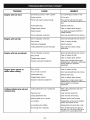
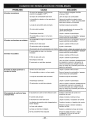
TROUBLE
CAUSE
Engine will not start
On/Off Stop Control is "OFF" position
Turn On/Off Stop Control to "ON"
Empty fuel tank
Fill fuel tank
Primer bulb wasn't pushed enough
Press primer bulb fully and slowly
5-7 times. Fuel should be visible in the
bulb
Fouled spark plug
Replace spark plug
Plugged spark arrestor
Clean or replace spark arrestor
Engine flooded
Use starting procedure WITHOUT
USING CHOKE
mixed fuel
Drain fuel tank/add fresh fuel mixture
Old or improperly mixed fuel
Drain fuel tank/add fresh fuel mixture
Dirty air filter
Clean or replace air filter
Carburetor misadjusted
Adjust carburetor
Cutting attachment bound with grass
Stop engine and clean cutting
attachment
Old or improperly mixed fuel
Drain fuel tank/add fresh fuel mixture
Dirty air filter
Clean or replace air filter
Plugged spark arrestor
Clean or replace spark arrestor
Improper carburetor adjustment
Take to any nonroad engine repair
establishment, individual or authorized
service dealer for carburetor
adjustment
Dirty air filter
Clean or replace air filter
No oil in fuel or old fuel
Drain fuel tank/add fresh fuel mixture
Fouled spark plug
Replace spark plug
Plugged spark arrestor
Clean or replace spark arrestor
Improper carburetor adjustment
Take to any nonroad engine repair
establishment, individual or authorized
service dealer for carburetor
adjustment
Old or improperly
Engine will not idle
Engine will not accelerate
Engine lacks power or
stalls when cutting
Cutting attachment
advance line
will not
REMEDY
Cutting
attachment
out of cutting
line
Refill cutting
cutting line
attachment
with new
Reel bound up
Clean reel and rewind line
cutting attachment dirty
Clean reel and reel housing
Indexing teeth worn or burred
Replace reel and reel housing
Line welded
Disassemble, remove at the welded
section and rewind the line
Line twisted
when refilled
Disassemble
Not enough
line is exposed
Push the Bump Knob and pull out
line until 4 in. (102 mm) of the line is
outside of the cutting attachment
- 21 -
and rewind line in reel
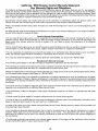
California / EPA Emission Control Warranty Statement;
Your Warranty Rights and Obligations
The California Air Resources Board, EPA (Environmental Protection Agency), and Sears, Roebuck, and Co. are pleased to
explain the emission Control System Warranty on your 2000 and later small off-roed engine, in California and the 49 states,
new small off-road engines must be designed, built and equipped to meet the state's stringent anti-smog standards. Sears
must warrant the emission control system on your small off-roed engine for the periods of time listed below provided there has
been no abuse, neglect or improper maintenance of your small off-roed engine.
Your Emission control system may include parts such as the carburetor or fuel-injection system, the ignition system, and
catalytic converter. Also included may be hoses, belts, connectors and other emission-related assemblies.
Where a warrantable condition exists, Sears will repair your small off-roed engine at no cost to you including diagnosis, parts
and labor.
The 2000 and later small off-roed engines are warranted for two years. If any emission-related part on your engine is defective,
the part will be repaired or replaced by Sears.
Owner's Warranty Responsibilities:
• As the small off-roed engine owner, you are responsible for the performance of the required maintenance listed in your
operator's manual. Sears recommends that you retain all receipts covering maintenance on your small off-road engine, but
Sears cannot deny warranty solely for the lack of receipts or for your failure to ensure the performance of all scheduled
maintenance.
• As the small off-roed engine owner, you should however be aware that Sears may deny you warranty coverage if your small
off-road engine or a part has failed due to abuse, neglect, improper maintenance or unapproved modifications.
• You are responsible for presenting your small off-road engine to an Authorized Sears Service Center as soon as problem
exists. The warranty repairs should be completed in a reasonable amount of time, not to exceed 30 days.
If you have any questions regarding your warranty rights and responsibilities, you should call 1-800-827-6655.
Manufacturer's Warranty Coverage:
• The warranty period begins on the date the engine or equipment is delivered to the retail purchaser.
• The manufacturer warrants to the initial owner and each subsequent purchaser, that the engine is free from defects in material
and workmanship which cause the failure of a warranted part for a period of two years.
• Repair and replacement of warranted part will be performed at no charge to the owner at an Authorized Sears Service Center.
For the nearest location please contact Sears at: 1-800-827-6655.
• Any warranted part which is not scheduled for replacement, as required maintenance or which is scheduled only for regular
inspection to the effect of "Repair or Replace as Necessary" is warranted for the period. Any warranted part which is scheduled
for replacement as required maintenance will be warranted for the period of time up to the first scheduled replacement point
for that part.
• The owner will not be charged for diagnostic labor which leads to the determination that a warranted part is defective. If the
diagnostic work is performed at an Authorized Sears Service Center.
• The manufacturer is liable for damages to other engine components caused by the failure of a warranted part still under
warranty.
• Failures caused by abuse, neglect or improper maintenance are not covered under warranty.
• The use of edd-on or modified parts can be grounds for disallowing a warranty claim. The manufacturer is not liable to cover
failures of warranted parts caused by the use of add-on or modified parts.
• In order to file a claim, go to your nearest Authorized Sears Service Center. Warranty service or repairs will be provided at all
Authorized Sears Service Centers.
• Any manufacturer approved replacement part may be used in the performance of any warranty maintenance or repair of
emission related parts and will be provided without charge to the owner . Any replacement part that is equivalent in
performance or durability may be used in non-warranty maintenance or repair and will not reduce the warranty obligations of
the manufacturer.
• The following components are included in the emission related warranty of the engine, air filter, carburetor, primer, fuel lines,
fuel pick up/fuel filter, ignition module, spark plug and muffler.
- 22 -
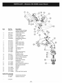
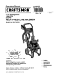
Item
Part No.
Description
1
753-04114
Throttle Housing and Trigger
Assembly (includes 2 & 3)
2
792-610314
Throttle Trigger Spring
3
753-04115
Throttle Trigger
4
791-182877
Throttle Cable Assembly
5
753-04116
Drive Shaft Housing
6
792-683295
Handle Bracket Assembly
(includes 7 - 12)
7
792-181811
Screw
8
9
791-181812
791-181813
Upper Handle Clamp
Middle Handle Clamp
10
11
791-181814
791-181815
Lower Handle Clamp
Nut
12
13
791-145569
791-612021
Anti-Rotation Screw
Tube Closure
14
791-612831
Grip
15
791-180687
16
753-04117
Assist Handle Assembly
(includes 13 & 14)
Flexible Drive Shaft
17
791-180547
Guard Mount Screw Assembly
18
791-181822
Guard and Blade Assembly
19
791-181823
Blade Assembly
20
791-153597
21
791-145569
Lower Clamp Assembly
(includes 21)
Anti-Rotation Screw
22
791-180549
Gearbox Assembly (includes 23)
23
791-153619
24
791-610660
Reel Housing and Eyelet
Assembly
Retainer
25
26
791-610317B
791-610318
Spring
Reel
27
791-153066B
Bump Head Knob Assembly
Optional
Accessories
791-181694
71-36549
@
@
@
Shoulder Strap Assembly
Craftsman 2-Cycle Oil
not shown
- 23 -
@
@
/
/
@
@
f
/
[
X'
@
@
@
'
/'
@
@
(_
- 24 i
,
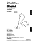
Item
1
Part No.
753-04105
Description
Air Cleaner/Muffler
Item
33
Part No.
791-181079
Description
Pull Handle
Assembly (includes 2 & 36)
34
791-613103
Rope
Air Cleaner Filter
Carburetor Mounting Screw
Assembly
Wavey Washer
35
791-181805
36
37
791-181862
791-182368
Starter Housing Assembly
(includes 28-35 & 41)
Housing Screw
Clutch Washer
Choke Lever Assembly
(includes 6)
Choke Knob and Screw
38
39
791-182369
791-153592
Clutch Rotor Assembly
Clutch Drum Assembly
40
791-612468
Spring
Cover
2
3
791-180350B
791-180351
4
791-180226
5
791-182160
6
791-182161
7
791-182162
Choke Lever and Plate
(includes 5)
41
791-181345
Cover Screw
8
753-04106
42
43
44
791-182797
791-145569
791-180036
Clutch Cover Assembly
Anti-Rotation Screw
Wire Lead
9
791-610675
Carburetor Assembly w/
Limiter Caps (includes 9 &21)
Carburetor Gasket
10
791-181860
Carb Mount Screw
45
753-04109
Module Assembly
11
791-181801
Primer and Hose Assembly
46
791-610311B
Spark Plug
12
753-1196
47
48
791-182068
753-04110
13
14
15
791-684451
753-04107
753-1208
Carb Mount Assembly
(includes 15)
Reed Assembly
Power Shaft Assembly
Carburetor Mount Gasket
49
791-147575
Exhaust Gasket
Muffler Assembly
(includes 47 & 49)
Muffler Mounting Bolt
Assembly
16
753-04108
50
753-04111
17
791-612134
Crank Case Service
Assembly (includes 10 & 24)
Rear Mounting Pad
51
753-1207
18
791-181802
52
53
19
20
791-182529
791-181168
Fuel Tank Assembly
(includes 19-21)
Fuel Cap Assembly
Fuel Return Une
753-1197
791-182723
753-04113
Cylinder Gasket
Cylinder Bolt
O.E.M. Carburetor Repair Kit
(Zama)
21
791-682039
Fuel Line Assembly
791-180091
22
791-145308
Front Mounting Pad
753-1209
Gasket Diaphragm Repair Kit
(Zama)
Piston Ring Set
23
24
791-153520
791-181861
Shroud Assembly
Shroud Screw
753-04112
Short Block Assembly
(items 10,14-16,24,46,50-53)
25
26
791-182064
791-181867
Shroud Extension and Stand
Flywheel Assembly
791-181501
791-610309
Starter Housing Screw Set
Crankcase Seal
27
28
791-181065
791-181897
Spacer
Recoil Pulley Assembly
791-182747
Spark Arrestor Kit
29
30
791-613102
791-181441
Recoil Spring
Pulley Retainer Assembly
not shown
31
32
791-611061
791-181804
Rope Guide
Switch Assembly (includes 44)
- 25 -
Cylinder Assembly
(includes 51 & 52)
Piston and Rod Assembly
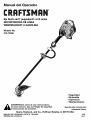
Manual del Operador
I:RI:IFTSMAN
Eje Recto de17 pulgadas/31 cc/2 ciclos
RECORTADORA DE LINEA
WEEDWACKER ®A GASOLINA
Modelo No.
316.74556
•
•
•
•
lea este manual y siga sus Reglas de seguridad
ADVERTENCIA:
antes de usar este producto,
e Instrucciones
de operacibn.
Sears, Roebuck,
and Co., Hoffman
MANUAL DEL OPERADOR, PARTE N° 769-00067
IMPRESO EN LOS EE.UU.
Seguridad
Ensamble
Operacibn
Mantenimiento
Guarde este manual para
referencia futura.
Estates,
IL 60179 USA
2/02
Revl
E2
Mantenimiento
E14
E2
Servicio y Ajustes
Almacenamiento
E16
E19
E7
Especificaciones
Resoluci6n de Problemas
E20
E21
Ensamble
E8
EPA
E23
Operaci6n
E10
Declaraci6n de Garantia Limitada
Advertencia
de la Proposici6n 65 de California
E2
Parachispas
Normas para una operaci6n segura
Contenidos de la Bolsa de Piezas
E3
GARANTiA TOTAL DE UN AI_O PARA LA CORTADORA
BRUSHWACKER®
DE MALEZAS
/ RECORTADORA
A GASOLINA
CRAFTSMAN@
Sears reparar& sin costo alguno cualquier defecto de material o de mane de obra durante un periodo de un are a partir de la fecha de
compra, siempre que esta Cortadora de Malezas Recortadora a gasolina Craftsman Brushwacker haya recibido el mantenimiento,
lubricacidn y puesta a punto de acuerdo con las instrucciones de operacidn y mantenimiento indicadas en el Manual del Operador.
Esta garantia excluye la linea de nil6n,
que se gastan durante el use normal.
bujlas de encendido
y filtro de aire, cabeza
de corte,
perilla percusiva
y las piezas
Siesta Cortadora de Malezas / Recortadora Brushwacker se utiliza con fines comerciales, esta garantia tendr& una vigencia de 90
dias. Si esta Cortadora de Malezas / Recortadora Brushwacker se utiliza con fines de alquiler, esta garantia tendr& una vigencia de 30
dias a partir de la fecha de compra.
Esta garantia tendr& validez solamente
mientras esta unidad sea utilizada en los Estados Unidos.
EL SERVICIO A TRAVES DE LA GARANTiA ESTAR,& DISPONIBLE CUANDO LLEVE LA CORTADORA DE MALEZAS / RECORTADORA
BRUSHWACKER A SU CENTRe DE SERVlCIO SEARS M,&S CERCANO EN LOS ESTADOS UNIDOS.
Esta garantia le otorga derechos legales especificos, yes posible que usted tambi6n tenga otros derechos que varian de acuerdo al estado.
Sears,
Roebuck
and Co., 1:)/817 WA, Hoffman
Estates,
LAS EMISIONES
PRODUCTO
QUiMICAS
IL 60179
DEL MOTOR
CONTIENEN
DE ESTE
SUBSTANCIAS
QUE EL ESTADO DE CALIFORNIA
CONOCE COMe CAUSANTES DE CANCER,
DEFECTOS DE NACIMIENTO U OTROS
DAI_IOS REPRODUCTIVOS.
NOTA: Para los usuarioe en tierras forestales de los EE.UU. y en los estados de California, Maine, Oregon y Washington. Toda la
tierra forestal de EE.UU. y del estado de California *C6digos de Recursos PQblicos 4442 y 4443), Oregon y Washington requieren, per !eY,
que ciertos motores de combusti6n operados en Areas de maleza forestales o recubierLas con cesped esten equipados con un
parachispas, que sean mantenidos en buenas condiciones de funcionamiento, o que el motor sea construido, equipado y mantenido para
la prevenci6n de incendios. Consuife con sus autoridades estatales o locales acerca de las normas relacionadas con dichos requisites. Si
no cumple con estos requisites, usted podria ser legalmente responsable o recibir una muifa. Esta unidad viene equipada de f_brica
con un parachispas. Si necesita cambiarlo, solicite que su centre Sears de servicios instale el accesorio NO182747, parachispas.
NOTA ESPECIAL: La exposicion a vibraciones mediante el use prolongado de herramientas manuales operadas a gasolina puede causar
daCtos en los vases sanguineos o nervios de los dedos, manes y arLiculaciones en las personas con predisposicion a problemas de
circulaci6n o a inflamaciones excesivas. El use prolongado durante el tiempo frio ha side relacionado con daSos de vases sanguineos en
personas sanas. Si ocurren sintomas come entumecimiento, dolor, p6rdida de fuerza, cambio en el color o textura de la piel, o p6rdida de
sensaci6n en los dedos, manes o arLiculaciones, abandone el use de esta herramienta y obtenga atenci6n m6dica. Un sistema de
antivibraci6n no garantiza la prevenci6n de estos problemas. Los usuarios que operan herramientas motricee en forma continua y regular
deben controlar de cerca su condici6n fisica y la condici6n de esta herramienta.
- E2 -
Los slmbolos de seguddad se utilizan para Ilamar su
atenci6n sobre posibles peligros. Los slmbolos de
seguridad y sus explicaciones merecen toda su atenci6n
y comprensi6n. Los simbolos de seguddad no eliminan
ningQn peligro por si mismos. Las instrucciones o
advertencias que ofrecen no substituyen las medidas
adecuadas de #revenci6n de accidentes.
SiMBOLO
I,_
SIGNIFICADO
seguridad puede conducir a que usted u otras
personas sufran lesiones. Siga siempre las
precauciones de seguridad para reducir el fiesgo de
ADVERTENCIA:
no seguir
una advertencia
de
incendio, descarga El
el6ctrica
y lesiones
personales.
SiMBOLO
DE ALERTA DE SEGURIDAD:
Indica peligro, advertencia o precauci6n.
Debe prestar atenci6n para evitar sufrir
graves lesiones personales. Puede ser
utilizado junto con otros simbolos o figuras.
NOTA: Le ofrece informaci6n o instrucciones que son
esenciales para la operaci6n o mantenimiento
del equipo.
IMPORTANTE
LEA TODAS
seguridad puede conducir a que usted u otras
personas sufran graves lesiones. Siga siempre las
precauciones de seguridad para reducir el fiesgo de
ELIGRO:descarga
El no obedecer
advertencia
de
incendio,
el6ctrica una
y lesiones
personales.
,_
INFORMACI6N
seguridad puede conducir a daSo patrimonial o a que
usted u otras personas sufran lesiones personales.
Siga siempre las precauciones de segufidad para
reducir
el fiesgo deElincendio,
el6ctrica de
y
PRECAUCION:
no seguirdescarga
una advertencia
lesiones personales.
DE SEGURIDAD
ADVERTENCIAS DE SEGURIDAD
RECORTADORES A GASOLINA
LAS INSTRUCCIONES
ANTES DE LA OPERACI6N
PARA LOS
• Lea todas las instrucciones con cuidado. Conozca bien los
controles y el uso correcto de la unidad.
ADVERTENCIA: La gasolina es muy infiamable y sus gases
pueden explotar si se encienden. Tome las siguientes
preoauciones:
• No opere esta unidad si est& cansado, enfermo, o bajo los
efectos del alcohol, drogas o medicamentos.
• Guarde el combustible en envases que hayan sido disefiados y
aprobados para el almacen_iento
de dichos materiales.
• Los niSos y los adolescentes menores de 15 a5os no deben
operar las unidades, excepto pot los adolescentes guiados
pot un adulto.
• Antes de Ilenar el tanque de combustible, apague siempre el
motor y espere que se enfrie. No retire nunca la tapa del
tanque de combustible ni cargue combustible mientras el
motor est6 caliente. No opere nunca la unidad sin la tapa del
combustible colocada firmemente en su lugar. Afloje la tapa
del combustible lentamente para disipar la presi6n del tanque.
• Inspeccione la unidad antes de utilizarla. Cambie las partes
da5adas. Verifique si existen p6rdidas de combustible.
AsegQrese de que los sujetadores est6n bien colocados y
asegurados. Cambie las pares accesorias de corte que est6n
quebradas, cascadas o dafiadas de cualquier forma. AsegQrese
de que el accesofio de corte est& bien instalado y ajustado con
firmeza. Asegt_rese de que la protecci6n accesefia de core est6
bien conectada y colocada segQn se recomienda.
• Mezcle y cargue el combustible en un &rea exterior bien
ventilada donde no haya chispas ni llamas. Quite lentamente
la tapa del combustible s61o despu6s de apagar el motor. No
fume mientras carga o mezcla el combustible. Limpie de
inmediato todo el combustible que se haya derramado.
• Use s61o linea de reemplazo Craftsman@ genuina de 0.080
pulgadas (2.03 mm) de diAmetro. Nunca use linea reforzada
con metal, cable o soga, etc., ya que pueden romperse y
convertirse en proyectiles peligrosos.
• Evite crear una fuente de encendido pot combustible
derramado. No arranque el motor hasta que se hayan disipado
los vapores del combustible.
• Aleje la unidad a por Io menos 10 pies (3 m.) del lugar de
carga de combustible antes de arrancar el motor. No fume,
mantenga las chispas y las llamas abiertas lejos del &rea
mientras carga el combustible u opera la unidad.
• Tenga en cuenta el riesgo de lesiones en la cabeza, manos
y pies.
• Limpie el &ma de corte antes de cada uso. Saque todos los
objetos como rocas, vidrios rotos, clavos, alambre o cuerda
que puedan salir despedidos o enredarse en el accesorio de
corse.
DURANTE LA OPERACI()N
• NO arranque ni opere la unidad en una sala o edificio
cerrado. Los gases de escape de mon6xido de carbono
pueden ser letales en un &tea cerrada. Opere esta unidad
s61o en un Area exterior bien ventilada.
• Aleje del &tea a todos los niSos, espectadores y animales
dom6sticos. Mantenga todos los ni_os, espectadores y
animales dom6sticos a un radio de por Io menos 15 m
(50 pies); aQn as[ puede existir un riesgo de objetos
despedidos contra los espectadores. Los espectadores
deben usar protecci6n para sus ojos. Si alguien se le
acerca, pare el motor y el accesorio de corte de inmediato.
• Use lentes o gafas de protecci6n que cumplan con las
normas ANSI Z87.1-1989, y protecci6n para sus oidos/audici6n
mientras opere esta unidad. Use siempre una m&scara facial o
para protegerse contra el polvo si la operaci6n levanta polvo.
• Use pantalones largos y gruesos y guantes. No vista ropa
holgada, alhajas, pantalones cor_os, sandalias ni est6
descalzo. Asegure su cabello sobre el nivel de los hombros.
• Optima el control del regulador y verifique que regrese
autom&ticamente a la posici6n de minima. Haga todos los
ajustes o reparaciones antes de usar la unidad.
• Esta unidad no fue diseSada para ser usada como
cor_amalezas. No conecte ni opere esta unidad con ningt_n
tipo de cuchilla ni accesorio para cortar malezas.
- E3 -
• La protecci6n accesoria de corte debe estar siempre
colocada 8n su lugar m_en_rasopere la unidad. No opere la
unidad con las dos lineas de corte extend_das, y la linea
correcta instalada. No extienda la linea de core m&s all& de
la Iongitud de la proteecion.
• Esta unidad cuenta con un embrague. El accesorio de
corte permanece estacionario cuando el motor estA
en marcha lenta. Si no Io hace. haga ajustar la unidad
per un establecimiento de reparac_6n, persona o
proveedor de serv_cio autorizado que arregle motores
para use fuera de la carretera.
• Ajuste la manija auxtl_ar a su medida de moao oue le brinde
el mejor agarre.
• AsegQrese oe que el accesorio de corse no esta en contacto
con ningun objeto antes de arrancar ]a unldad.
• Use la unidad unicamente con la luz del die o con buena luz
artificial.
• Evite arrancar la unidad accidentalmente. Col6quese en
posici6n de inicio siempre que tire de la cuerda de
arran(]ue. El operador y la unidad deben estar en una
posici6n estable al comenzar. Vea Instrucciones de
encendido y apagado en la secci6n de Operacibn.
• Use la herramienta adecuada para el trabajo y use
esta herramienta solamente aara sus fines.
• No se estire demasiado.
eouilibrio adecuados.
Mantenga siempre una posici6n y
• Sostenga s_empre la unidad con ambas manes m_entras
este en funcionamiento. Sostenga con firmeza tanto el
mango come la manila auxiliar.
• Mantenga las manes, la care y los p_es lejos de todas las
pares m6viles. No intente tocar ni detener el accesorio ae
cor[e m]entras gira.
• No toeue el silenciador ni el cilindro. Estas pares se
calientan touche con la operacion. Luego ee apagarlas
permanecen calientes durante un corto t]empo.
• No opere el motor a una ve]ocidad mayor aue la necesaria
para coRa£ recortar o recortar los bordes. No haga funcionar
el motor a alta velocidad mientras no est& cortando.
• Apague siempre el motor cuando demore el core
mientras camina entre zonas de corte.
o
• Si golpea o se enreda con alg[_n objeto extrafio, apague el
motor de inmediato y verifique si hay defies. Repare todos
los dafios antes de volver a intentar operar la unidad. No
opere la unidad Si tiene piezas flojas o dafiadas.
t Apague el motor para realizer todo el mantenimiento,
reparaciones o cambio del accesorio de corte u otros
accesorios.
• Use solamente repuestos legitimos cuando realice el
servicio de esta unidad. Estas piezas est&n disponibles en
su distribuidor autorizado. No use piezas, accesorios ni
auxiliares que no hayan side disefiados pare esta unidad.
Su use puede conducir a que el usuario sufra graves
lesiones o al dafio de la unidad y ala invalidacion de su
garant!a.
• Mantenga la unidad libre de vegetaci6n y otros materiales.
Puede n al0jarse ent re e! acces0do de corLe y Ia pr0tecci6n.
•Para reducir el riesgo de incendio, cambie los silenciadores
y amortiguadores de chispas defectuosos, mantenga el
motor y el silenciador libre de paste, hojas, grasa excesiva o
acumulaciones de carbono.
OTRAS
ADVERTENCIAS
DE SEGURIDAD
• No guarde nunca la unidad con combustible en el tanque
en un edifieio donde los gases puedan Ilegar a una llama
abierLa o a una chispa.
• Espere que el motor se enfrie antes de guardar o
transportar la unidad. Asegt_rese de que la unidad est6
segura al transP0rtarla .
• Guarde la unidad bajo Ilave en un lugar adecuado y seco
pare evitar que sea usada per personas no aut0rizadas y se
dafie, fuera del alcance de los nifios.
t Nunca moje ni rocfe la unidad con ague ni con ningt_n otro
liquido.
Mantenga las manijas secas, limpias y sin residues.
Limpie la unidad luego de cada use. Vea las secciones de
Mantenimiento y Almacenamiento.
• Guarde estas instrucciones. Cons_ltelas con frecuencia y
utilicelas
para ensefiar a otros usuarios. Sile presta esta
unidad a alguien, pr6stele tambi6n estas instrucciones.
GUARDE
ESTAS INSTRUCCIONES
SIMBOLOS DE SEGURIDAD
E INTERNACIONALES
Este manual del operador describe los simbolos y figuras de seguridad e intemacionales que pueden aparecer en este producto. Lea
el Manual del Operador para obtener informaci6n completa acerca de la seguridad, ensamble, operaci6n y mantenimiento y reparaci6n.
S|MBOLO
SIGNIFICADO
• SiMBOLO
DE ALERTA
Indica peligro, advertencia
©
e
• ADVERTENCIA
DE SEGURIDAD
o precauci6n.
Puede ser utilizado junto con otros simbolos o figuras.
- LEA EL MANUAL
DEL OPERADOR
Lea el Manual del Operador y siga todas las advertencias e instrucciones de seguridad.
De no hacerlo, el operador y/o los espectadores
pueden sufrir graves lesiones.
• USE PROTECCI6N
OCULAR
Y AUDITIVA
ADVERTENCIA: Los objetos arrojados por la unidad y el ruido fuerte pueden causar graves
lesiones oculares y perdida auditiva. Utilice protecci6n ocular que cumpla con las normas
ANSI Z87.1 y protecci6n auditiva cuando opere esta unidad.
• MANTENGA
ALEJADOS
A LOS ESPECTADORES
ADVERTENCIA:
Mantenga a todos los espectadores, en especial a ni_os y animales
domesticos a por Io menos 50 pies (15 m.) del &rea de corte.
5"7x
• BOMBILLA
Oprima
DEL CEBADOR
la bombilla
• COMBUSTIBLE
del cebador
completa
y lentamente,
SIN PLOMO
Use siempre combustible
limpio, nuevo y sin plomo.
- E5 -
de 5 a 7 veces.
SiMBOLO
SIGNIFICADO
• INDICADOR
DE ACEITE
Consulte el manual del operador para obtener informaciSn acerca del tipo correcto de aceite.
• LOS OBJETOS DESPEDIDOS
CAUSAR GRAVES LESIONES
/ /
Y LA CUCHILLA
ROTATIVA
PUEDEN
ADVERTENCIA: No opere esta unidad si la protecciSn pl&stica de linea no est& colocada
en su lugar. Mant6ngase alejado del accesorio de corte giratorio.
I
O
• CONTROL
DE ENCENDIDO
ENCENDIDO /ARRANQUE
• CONTROL
Y APAGADO
/ MARCHA
DE ENCENDIDO
Y APAGADO
APAGADO O PARADO
• ADVERTENCIA
DE SUPERFICIE
CALIENTE
No toque un silenciador ni un cilindro caliente. Puede quemarse. Estas partes se calientan
mucho con el uso. Luego de apagarse permanecen calientes durante un corto tiempo.
m
• CUCHILLA
AFILADA
ADVERTENCIA: La protecci6n del accesorio de torte contiene una cuchilla afilada. Para
prevenir graves lesiones, no toque la cuchilla.
A
I-I
B
/k®/
C
• CONTROL
DEL OBTURADOR
A. Posici6n de Obturaci6n Completa
B. Posici6n de Obturaci6n PARCIAL
C. Posici6n de FUNCIONAMIENTO
• NO USE CUCHILLAS
ADVERTENCIA: Para prevenir graves lesiones, no conecte ni opere la unidad con
ningt_n tipo de cuchilla.
- E6 -
Protecci6n de
Linea de 17"
Botella de Aceite
Manija Auxiliar
Manual del
Operador
(3) Tomillos (10-24 x 1/2) - para
la Protecci6n de la Linea
(3) Contratuercas
hexagonales (#10-24) para
la Protecci6n de la Linea
(4) Tuercas de presi6n
hexagonales(1/4 x 20) para
la Manija Auxiliar
Abrazadera
Superior de
la Manija
(4) Tornillos (1/4-20 x 2-1/4)
- para la Manija Auxiliar
Abrazadera
Media de la
Manija
- E7 -
CONTENIDO
DE LA CAJA
•
Recortadora
•
Paquete de Piezas
HERRAMIENTAS
ENSAMBLE
•
Destornillador
INFORMACI(_N
NECESARIAS
PARA EL
Phillips Grande
ACERCA
DEL ENSAMBLE
Para garantizar una operaci6n segura y correcta de su
unidad, todas las partes y piezas que usted ensamble
deberAn ser ajustadas con firmeza.
ENSAMBLE
Y AJUSTE
DE LA MANIJA
4.
Sostenga cada tuerca hexagonal en la ranura de la
abrazadera inferior con un dedo. Comience los tomillos
con un destomillador Phillips grande. No los aiuste
hasta haber ajustado la manija.
5.
Deslice la manija auxiliar hacia adentro o hacia afuera
hasta que la flecha/linea blanca de la calcomania
toque el ensamble de la abrazadera (Fig. 2).
6.
Mientras sostiene la unidad en posici6n de operaci6n
(Fig. 3), coloque la manija auxiliar en el lugar que le
brinde el mejor agarre.
7. AJuste los tornillos de la abrazadera en forma pareja
hasta que la manija auxiliar este firme.
AUXILIAR
1. Coloque la manija auxiliar entre la abrazadera
superior y la abrazadera media (Fig. 1).
2.
Calcomania
Mientras sostiene las tres piezas juntas, instale los
cuatro (4) tornillos a trav6s de la abrazadera superior
y en la abrazadera media.
.
NOTA: Los orificios de la abrazadera superior y la
abrazadera media estarAn alineados s61o cuando se
ensamble en forma correcta.
3.
Coloque las abrazaderas y la manija auxiliar sobre el
bastidor del eje y encima de la abrazadera inferior.
Fig. 2
Tornillos
Manija auxi!iar
Abrazadera
media de la
manija
Abrazadera
inferior de la
manija
Braze
. ,
Tuercas
Fig. 1
Fig. 3
- E8 -
_J
INSTALACI6N
DE CORTE
DEL PROTECTOR
ACCESORIO
Protector accesorio
de corte de 17"
Siga las siguientes instrucciones si el protector accesorio
de corte no est& instalado en su unidad.
_
sin
el protector accesorio
corte lacolocado
en
DVERTENCIA:
No operedenunca
recortadora
su lugar para evitar graves lesiones personales.
Montaje del protector
1. Deslice el protector accesorio de corte en el montaje
del protector sobre el accesorio de corte. AIinee los
orificios de los tornillos del protector con los orificios
del accesorio de corte (Fig. 4).
2.
Coloque una contratuerca hexagonal en uno de los
tres orificios c6ncavos de la parte superior del
protector accesorio de corte (Fig. 5).
3.
Instale un tornillo en el orificio de la base del protector
accesorio de corte y atomfllelo en la tuerca instalada
en el paso #2 (Fig. 6). No Io ajuste.
4.
Repita los pasos 2 y 3 hasta que los tres tornillos se
hayan comenzado a colocar, entonces apdete los
tornillos firmemente con un destornillador adecuado.
Accesorio de corte
Fig. 4
(3) Contratuercas
hexagonales
Parte superior
de la
contratuerca
\ Muescas
Fig. 5
\
(3) Torninos
Fig. 6
- E9 -
CONOZCA
SU RECORTADOR
DE LiNEA
LEA ESTE MANUAL DEL OPERADOR Y LAS NORMAS DE
SEGURIDAD ANTES DE OPERAR SU RECORTADORA DE
LINEA. Compare las figuras con su recortadora de linea
para conocer bien la ubicaci6n de los diferentes controles y
ajustes. Guarde este manual para su referancia futura.
CONTROL DE ENCENDIDO
Y APAGADO
f
DISPARADOR
DEL ESTRANGULADOR
TAPADEL COMBUSTIBLE
'\
--
MANIJA AUXIMAR
BOMBILLA
DEL CEBADOR
BRAZO
/
BOMBILLA DEL CEBADOR
PROTECTOR
ACCESORIO
CONTROL DE ENCENDIDO Y APAGADO - se usa para
encender y apagar el motor. El interruptor debe estar en
posiciSn de ON al arrancar el motor.
ACCESORIO
DE CORTE
BOMBILLA DEL CEBADOR - extrae el aire de las tuberias
del combustible y Ilena el carburador con combustible.
CONTROL DEL REGULADOR - controla la velocidad del
motor para diversas condiciones de corte.
MANIJA AUXILIAR - se usa para sostener la recortadora
de linea durante la operaciSn.
PROTECTOR ACCESORIO DE CORTE - protege al
operador de los residuos que salen despedidos. Contiene
la cuchilla cortadora de llnea para verificar que la linea no
se extienda m&s all& de la Iongitud adecuada. El protector
accesorio de corte debe estar instalado en todo
momentoque use el accesorio de corte.
ACCESORIO DE CORTE - consiste en un bastidor para
el carrete, el carrete, el resorte, la perilla percusiva y la
llnea de corte.
- El0 -
ESTE MOTOR
PARA ALIMENTAR
ESTA CERTIFICADO
PARA OPERAR CON
GASOLINA SIN PLOMO Y ACEITE.
EL MOTOR
DE
Use de Combustibles de Mezcla
Si usted decide utilizar un combustible mezcla o su uso es
inevitable, le recomendamos que siga las precauc!ones
siguientes.
PRECAUCION: Asegt_rese de leer estas
instrucclones con culdado antes de intentar
encenaer u operar esta Jn_aaa. El utilizar aceite o
combustible vielos o no adecuados puede daSar el
motor. Este tipo de daSo ANULARA la garantia del
motor.
1.
Use siempre mezcla de combustible nueva conforme a !as
instrucciones de su manual de! operador.
2.
Use un aditivo especial,
3.
ADVERTENCIA: La gasolma es extremaaamente
inflamable y sus gases pueden explotar si son
encena_aos. Detenga s_empre el motor y espere que
se enfrie antes de Ilenar el tanaue del combustible.
Mantenga las chispas y las llamas abiertas lejos ael
&rea.
Siempre agite la mezcla de combustible
alimentar la unidad.
4.
antes de
Drene el tanque y haga funcionar el motor en seco antes
de guardar la unidad.
Use de un estabi!izador de combustible
Si utiliza una marca de aceite que no sea Craftsman, el uso de
un estabilizador impedir& la corrosi6n y reducir,_ la formaciOn
de un dep6sito de goma. Agregue 0.8 onzas (23 m!) de
estabilizador por galOe de combustibles segQn las
instrucciones del envase. NUNCA agregue estabilizador de
combustible directamente en el tanque de combustible de la
unidad. El uso de un estabilizador de combustible puede Iograr
que el combustible se mantenga fresco durante seis (6) meses.
Tipo de Aceite Recomendado
Su producto viene con una botella de aceite de motor ae 2
ciclos Craftsman de 3.2 onzas (95ml), el cual contlene
estabilizador de combustible. Se recomienda el aceite marca
Craftsman para esta herramienta elOctrica de exteriores. Si se
utiliza otra mama. asegQrese de aue sea ace_te ae buena
calidad, formulado para motores de 2 ciclos enfriados por
aire.
A
0
PELIGRO: La mezcla de combustible contiene
dest_lados de petr61eo. Mantenga]o lejos del calor o
de la llama abierLa. Su ingestion puede eer nociva o
fatal. En caso de ingesti6n, no provoque el vomlto
LLAME A UN MEDICO INMEDIATAMENTE. Evite
el contacto prolongaao con la p_el. L_vese bien
luego de usado. No vuelva a usar la botella.
Tipo recomendado
UNA MEZCLA
PEMGRO: Para que el motor funcione en forma
adecuada y con una m&xima confiabilidad, preste
mucha atenci6n alas instrucciones de mezcla de
aceite y combustible del envase de aceite de 2
ciclos. Use una proporciOn de combustible / aceite
de 40:1. Use aceite de 2 ciclos. El usar aceite
mezclado en forma incorrecta puede daSar
sedamente el motor.
de combustible
Use gasolina s_n plomo limpia y nueva que tenga menos de 60
dias de almaceeamiento.
Instrucciones para mezclar el aceite y el combustible
Mezcle bien la proporciOn adecuada de 40:1 de gasollna s_n
plomo con aceite de motor de 2 c_clos en una lata de
combustible pot separado. No las mezcle directamente
en el tanque de combustible del motor.
GASOMNA SIN PLOMO
1 GAL6N
Use 3.2 onzas (95ml) de aceite de motor de 2 ciclos por caaa
gal6n de gasolina sin plomo para Iograr una proporcl0n entre
el combustible y el aceite de 40:1.
ACEITE SEARS DE 2 CICLO_
DE EE.UU. + 3,20NZAS
(3.8 LITROS)
1 LITRO
PROPORCI(_N
- Ell
-
FLUIDAS
(95 ml)
+
25 ml
DE LA MEZCLA
- 40:1
IMPORTANTE
La experiencia indica que los combustibles con mezcla de
alcohol (llamados gasohol o que usan etanol o metanol)
pueden atraer humedad Io coal conduce a la separaci6n y
formaci6n de &cidos durante el almacenamiento. El gas
&cido puede da_ar el sistema de combustible de un motor
mientras se encuentra en almacenamiento. Para evitar
problemas en el motor, vacie el sistema de combustible
antes de almacenarlo durante 30 o mAs dfas. Drene el
tanque de combustible, arranque el motor y deje que
funcione hasta que las tuberias de combustible y el
carburador est_n vacios. Use combustible nuevo al volver
a utilizarla la prSxima estaci6n.
CONTROL DE _"
ENCENDIDO Y
APAGADO
Fig. 7
No coloque nunca productos de limpieza para el motor o
carburador en el tanque de combustible ya que pueden
causar dados permanentes.
Lea la secci6n de AImacenamiento
informaci6n adicional.
INSTRUCCIONES
para obtener
Palanca
DE APAGADO
1. Coloque el control de encendido y apagado en
posiciSn de "OFF" (apagado) (Fig. 7).
INSTRUCCIONES
_
Bombilla del
cebador
DE ENCENDIDO
NOTA: Mezcle la gasolina con el aceite (proporci6n de 40:1).
Vea Instrucciones
de mezcla de aceite y combustible
en la secci6n de Operacibn. Llene su unidad con la
mezcla de aceite y gasolina y colSquela sobre el piso para
comenzar (Fig. 9).
Fig. 8
1. Coloque el control de apagado y encendido en posici6n de
"ON" (encendido)(Fig. 7).
2.
Oprima completamente y suelte la bombilla del cebador de 5
a 7 veces. El combustible debe estar visible en la bombilla
(Fig. 8).
3.
Mueva la palanca del obturador (Fig. 8) a la posici6n CHOKE
(H A).
4.
Oprima y sostenga el disparador y tire de la cuerda de
arranque (Fig. 9) hasta que el motor intente arrancar (tire un
m&ximo de 5 veces).
5.
Mueva la palanca del obturador a
6.
Tire de la cuerda de arranque (Fig. 9)
hasta que el motor arranque (tire un
m_tximo de 3 veces).
Cuerda de
arranque
(1',1s).
7.
Si el motor no arranca luego de 3 veces, repita los pasos 2 a 6.
8.
Espere que el motor funcione durante 10 segundos, luego
mueva la palanca del obturador a la posici6n de RUN (1÷[ O).
Control del
regulador
v
Fig. 9
NOTA: Cuando el motor estA caliente, vaya directamente
al Paso 5 anterior. Mueva la palanca del obturador a la
posici6n de (N B).
NOTA: Si el motor se inunda al intentar arrancar la
unidad coloque la palanca del obturador en la posici6n
de MARCHA (RUN) (C) ÷ (Fig. 8). Oprima el control del
regulador. Tire de la cuerda de arranque r&pidamente. El
motor debe arrancar luego de tres (3) a ocho (8) tirones.
- E12 -
C6MO
SOSTENER
EL RECORTADOR
,_
sus ojos, audici6n, pies y cuerpo para reducir
ADVERTENCIA: Use siempre protecci6n para
el riesgo de una lesi6n al operar esta unidad.
Cada vez que golpea la cabeza, se suelta
aproximadamente 1 pulgada (25.4 mm) de line& Una
cuchilla ubicada en la protecci6n cortarA la linea en su
Iongitud adecuada si se suelta mAs iinea que la necesaria.
Para obtener mejores resultados, golpee la cabeza
sobre el terreno limpio o la tierra dura. Si intenta soltar
la linea sobre el c6sped alto, el motor puede ahogarse.
Antes de operar esta unidad, pArese en posici6n de
operaci6n (Fig. 10). Verifique Io siguiente:
ADVERTENCIA: No retire ni aitere el ensambie
de la cuchilia de corte de llne& La Iongitud de
linea excesiva puede conducir al recalentamiento
del embrague y causar graves lesiones
personales.
• El operador tiene protecci6n ocular y ropa adecuada.
• El brazo derecho estA levemente doblado, y la mano
esta sosteniendo el mango del eje.
• El brazo izquierdo estA recto, y la mano estA sosteniendo
la manija.
RECORTE DECORATIVO
• La unidad esta debajo del nivel de la cintura.
Reaiice un recorte decorativo eliminando toda la vegetaci6n
de airededor de Arboles, postes, cercos, etc.
• El accesorio de corte esta paralelo al suelo y hace facil
contacto con la vegetaci6n que va a ser cortada sin
que el operador tenga que inclinarse.
Gire toda la unidad a modo de que la cabeza se ubique
a un Angulo de 30 ° con el piso (Fig. 12)
POSICI()N ADECUADA
Cuando opere la recortadora, mantenga una posici6n y
equilibrio adecuados. Sostenga la recortadora con ambas
manos (Fig. 10). No se estire demasiado y mantenga
todas ias partes de su cuerpo iejos de la cabeza de corte.
Fig. 11
Fig. 10
AJUSTE
CORTE
DE LA LONGITUD
DE LA LJNEA DE
Su recortadora esta equipada con una cabeza de corte
que permite que el operador suelte mAs linea sin tener que
apagar el motor. Para soltar mas linea, golpee ligeramente
la cabeza contra el piso mientras opera la recortadora a
alta velocidad (Fig. 11).
\
NOTA: A medida que la linea se acorta, es mAs dificil
soltarla. Mantenga siempre la linea de corte extendida
en su maxima Iongitud de corte.
Fig. 12
- E13 -
NOTA:
NOTA:
AIgunos procedimientos de mantenimiento pueden
requedr el uso de herramientas o habilidades
especiales. Si no est& seguro acerca de estos
procedimientos, Ileve su unidad a un establecimiento de
reparaci6n, persona o proveedor de servicio autorizado
que arregle motores pars uso fuera de la carretera.
PROGRAMA
DE MANTENIMIENTO
A fin de garantizar el mAximo desempeto del motor, puede ser
necesario inspeccionar la lumbrera de escape del motor despu6s
de 50 horas de funcionamiento. Si usted observa p6rdida de
RPM, funcionamiento deficiente o falta general de aceleraci6n,
es posible que sea necesario realizar este mantenimiento. Si
usted considers que su motor necesita esta inspecci6n, hags
que un establecimiento de reparaci6n, persona o proveedor de
servicio autorizado que arregle motores pars uso fuera de la
carretera le preste el servicio. NO intente realizar este proceso
usted mismo ya que puede ocasionar datos al motor producto
de los contaminantes que se encuentran en el proceso de
limpieza de la lumbrera.
Estos procedimientos requeridos para el mantenimiento
deben ser realizados con la frecuencia indicada en la tabla.
Deben ser incluidos como parte de toda puesta a punto de
cada temporada.
nunca realice mantenimiento ni reparaciones con la
DVERTENClA:
ParaRealice
evitar siempre
lesiones el
personales
graves,y
unidad
funcionando.
mantenimiento
_
las reparaciones con la unidad frfa. Desconecte el cable
de la bujia de encendido pars cerciorarse de que la
unidad no arrancar&
FRECUENCIA
Antes
de arrancar
MANTENIMIENTO
el motor
REQUERIDO
Llene el tanque de combustible
de aceite y combustible.
Verifique que no existan partes
CONSULTE:
la mezcla
flojas
correcta
ni dafiadas.
Limpie
Cada 25 horas
Examine el parachispas
y limpielo.
Inspeccione
la condici6n
y la separaci6n
RECOMENDACIONES
a aceitar
con
Cada 10 horas
Cada 50 horas
y vuelva
El mantenimiento, la sustituci6n o arreglo de
dispositivos pars el control de emisiones y sistemas
pueden set hechos por cualquier establecimiento de
reparaci6n, persona o proveedor de servicio
autorizado que arregle motores para uso fuera de la
carretera.
el filtro de aire.
de la bujia de encendido.
Inspeccione si la lumbrera de escape y la rejilla del parachispas estan
tupidas u obstruidas para garantizar los niveles maximos de rendimiento.
GENERALES
Mantenga los orificios de ventilaci6n
todo momento.
ADVERTENCIA: Pars evitar graves lesiones
personales no realice nunca el mantenimiento de la
unldad mientras est& en marcha. Apague la anidad v
espere que se enfrie antes de realizar ningun
rnantenimiento. Desconecte la bajia de encendido
pars evitar que la anidad arranaue.
MANTENIMIENTO
DEL FILTRO
P&gina
E11
P&gina
E14
P&gina
P&gina
E18
E15
P&gina E18
libres de residuos en
DE AIRE
NOTA: Limpie y vuelva a aceitar el filtro de aire cada 10 horas
de uso. El filtro de aire de su unidad es una de las _reas mas
imporLantes que debe mantener. Si no se mantiene, su
garantia set& ANULADA. Antes de limpiarlo, verifique que la
unidad est 6 apagada,
La garantia de este recor_ador de linea no cubre los elementos
aae han sido sometidos al abaso o negligencia del operador.
Para recibir el valor completo ae Eagarantia, el operador aebe
mantener esta unidad segQn se indica en el manual del operaao_
Remocibn de la cubierta del filtro de aire / silenciador
1.
Estos proced_mtentos de manten_m_ento requerido deben set
realizados con la frecuencia _nd_caaa en la tabla. Tambi_n
aeben ser inclaidos como parte de toda puesta a punto de
carla temporaaa.
Coloque la palanca del obturador en posici6n de
obturaci6n parcial (PARTIAL) (B).
NOTA: La palanca del obturador debe estar en la posici6n de
obturaci6n parcial (PARTIAL) (B) (Fig. 13) para retirar la
cubierLa del filtro de aire / silenciador.
INSPECCIONE SI EXISTEN PARTES DAI_IADAS O
DESGASTADAS
Palanca del obturador
Inspecc_one la unidad para vet si existen parces daSadas o
aesgastadas. Repare o cambie las partes datadas antes de
operar la unidad.
o btPOaS
,cC
,6bnnpds
ec iaI
INSPECCIONE SI EXISTEN PARTES
SUJETADORAS QUE ESTEN FLOJAS
• Accesorio de corLe
• Tuercas y tomillos hexagonales
de a manija aux_har
Tornillo
Tornino
• Tornillos del protector accesono de corte
I
I
I
• Cable de la bujla ae encene_eo
LIMPIE
LA UNIDAD
I
I
I
I
I
I
I
I
I
Y LAS ETIQUETAS
• Limpie ]a unidad y las etiquetas con un patio hQmedo y un
detergente suave.
Fig,
• Seaae la unidad con un patio limpio y seco.
- E14 -
13
2,
Saaue los cuatro (4) tornillos aue sostienen la cubierta de]
filtro de aire / silenciador (Fig. 13L Use un destornillaaor
de v&stago piano o un destornillador de broca T-20.
3.
Saaue la cubierta del motor. No la fuerce.
Limpieza del filtro de aire
1, Saaue la cubierta del filtro de aire / silenciador. Vea
Remocibn de la cubierta del filtro de aire / silenciador
en la secci6n de Mantenimiento.
2.
Saaue el filtro de aire de atr&s de la cubierta del filtro de
aire / silenciador (Fig. 14L
3.
Lave el filtro en agua y detergente (Fig. 15). Enjuague Z
bien el filtro. Escurra el exceso de agua. D6jelo secar por
completo.
4.
Aplique suficiente aceite nuevc SAE 30 para recubnr el
filtro llgeramente (Fig. 16).
5.
Apriete el filtro para esparc_r y reurar el exceso de aceite
(Fig. 17).
6.
Vuelva a colocar el filtro de abe en la cubierta del
filtro de aire ! silenciador (Fig. 14L
Fig. 15
NOTA: La operaci6n de la unidad sin el filtro de aire y el
ensamble de la cubierta del filtro de aire / silenciador
ANULAR/_ la garantia.
Fig. 16
Reinstalaci6n de la cubierta del filtro de aire / silenciador
1 Coloaue la cubierta del filtro de aire / silenciador sobre la
parte posterior del carburador y sJlenclador.
NOTA: La palanca del obturador debe estar en la posicion de
obturacion parcial (PARTIAL) (B) (Fig. 13) para
instalar la cubierta del filtro de aire / silenciador.
2.
Inser[e los cuatro (4) tornillos en los orificios de la cubierta
del filtro de alre / sllenclador (Fig. 13) y a]Qstelos. No los
ajuste demas_aao.
Z
CAMBIO DE LA BUJIA DE ENCENDIDO
Use una bujia Champion RDJ7Y (o similar). La separaci6n
correcta de aire es 0.020 pulg. (0.50 ram). Saque la bujia cada
25 horas de operacion e mspeccione su condicion (Fig. 18/.
1
Pare el motor y separe el alambre de la bujia de
encendldo.
2.
Limpie alrededor de a bujia de encen@do y s&quela de la
cabeza de] cilindro.
Fig. 17
NOTA: Cambie las bujias de encendido que esten rajaaas.
detenoraclas o suclas. No las limple ooll chorro de arena, nl
raspe n_limpie los electrodos ya que el motor podria daSarse
si penetran pequeSas parLiculas en el cilindro.
3.
4.
0.020 pulgadas
(0.50 mm)
Fije la separacion de aire en 0.020 pulg. (0.50 mm) con
una galga ae alambre (Fig. 18/. Instale una bujia ae
encendldo con la separacion adecuada en la cabeza del
cilindro. Ajt_stela a 110-120 pulg.olibras (12.3-13.5 N,m).
t
Reemplace el cable de la bujia.
Fig. 18
Filtro d_
Fig. 14
- E15 -
LIMPIEZA
DE LA RECORTADORA
DE LJNEA
\
No use detergentes fuertes para limpiar el bastidor de
pl&stico ni la manija. Estas piezas pueden da_arse ya que
ciertos productos dom_sticos de limpieza contienen
aceites arom&ticos como pino y limSn y solventes como el
querosene. Seque toda la humedad con un pado suave.
,_
Perilla percusiva
Perno cautivo
la unidad antes de realizar el servicio de la
ADVERTENCIA: Para prevenir lesiones, apague
cabeza de corte.
INSTALACI6N
DE CORTE
Bastidor del carrete
DE LA L|NEA PARA LA CABEZA
Fig. 19
_
Bastidor del
La linea de corte de la cabeza de corte puede ser
reemplazada utilizando dos m6todos diferentes:
carrete
• Bobinando el carrete con llnea nueva, o
Resorte
//'1
• Instalando un carrete prebobinado.
Uso de la linea correcta
,_
repuesto para la recortadora Craftsman ® Para
ADVERTENGIA: Utilice siempre una llnea de
evitar lesiones, no use linea reforzada con metal.
_((,',
Fig. 20
Es muy importante que utilice el tama_o correcto de
linea. Use una llnea con un di&metro de 0.080 pulgadas
(2.03 mm). Si usa una linea de mayor di&metro, el motor
puede recalentarse y fallar.
\\
Remocibn del carrette
1. Sostenga el bastidor del carrete con una mano y
destomille la perilla percusiva en sentido antihorado
(Fig.19). Inspeccione el pemo cautivo dentro de la perilla
percusiva para asegurarse de que puede moverse
libremente. Cambie la perilla percusiva si estA dadada.
2.
Retire el carrete interno y el resorte (Fig. 20).
3.
Use un pado limpio para limpiar la superficie interior
del bastidor del carrete (Fig. 21).
Fig. 21
NOTA: Limpie siempre el carrete, el bastidor del carrete
y el eje antes de volver a ensamblar la cabeza de torte.
4.
Inspeccione los dientes indicadores del carrete y del
bastidor del carrete por si estAn desgastados. Si es
necesario, retire las rebabas o cambie el carrete o el
bastidor del carrete (Fig. 22).
- E16 -
==_
C_=
rrete
interno
Bobinado del Carrete
1. Tome aproximadamente 25 pies (7.6 m) de linea de
corte nueva. Enl&cela en dos largos iguales. Inserte
cada extremo de la linea a trav6s de uno de los dos
orificios del carrete. Tire de los extremos en forma
equivalente hasta que el lazo es del menor tama_o
posible (Fig. 23).
2.
Coloque su dedo indice entre las dos lineas para
impedir que se superpongan (yea la Fig. 24).
3.
Bobine las dos lineas al mismo tiempo en capas
parejas y ajustadas en el carrete, en la direcci6n
indicada en el carrete (Fig. 24).
Lazo
Fig. 23
NOTA: Si no bobina las lineas en la direcci6n indicada,
la cabeza de corte funcionar& en forma incorrecta.
4.
Inserte uno de los extremos de la linea en cada
ranura de fijaci6n (Fig. 25).
Nueva instalacibn del Carrete
1. Inserte un extremo de la linea a trav6s de cada ojalillo
en el bastidor del carrete, e inserte el carrete y el
resorte nuevamente en el bastidor del carrete (Fig. 26).
2.
Tome los extremos de la linea y tire firmemente para
liberarlas de las ranuras de fijaci6n del carrete.
3.
Sostenga el carrete en su lugar y atornille la perilla
percusiva en sentido horatio nuevamente en el
carrete (yea la Fig. 19).
INSTALACI6N
Carrete_J_-'_
Fig. 24
\
DE UN CARRETE PREBOBINADO
1. Obtenga un carrete prebobinado adecuado de linea
de corte. Lea la secci6n de Uso de la linea correcta.
2.
Siga las instrucciones de las secciones de
Remocibn del carrete y Nueva instalacibn
carrete.
del
¢ 7
Ranuras de
fijaci6n
\
Fig. 25
\
Bastidor
Resorte
Fig. 22
-_
"J__
//
Fig. 26
- E17 -
cadeelte
Carrete
MANTENIMIENTO
Nota:
1.
2.
3.
4.
5.
6.
7.
DEL PARACHISPAS
El flujo de las emisiones puecle ser en una
direccion solamente: APARTANDOSE del motor.
Preste mucha atenci6n a c6mo se ensambla el
silenciador, de modo que Io pueda volver a
armar exactamente como est&. El no hacerlo asi
daSara a la unidad y pudiera causar lesiones
personales graves.
Silenciador
Quite la cubierta del silenciador/filtro de aire. Yea las
instrucciones que aparecen en este manual para
quitar la cubierta.
Parachispas
Ubique el silenciador y encuentre los dos (2)
tomillos en la parte inferior del silenciador (Fig. 27).
Estos dos tornillos fijan el conjunto del deflecto- de
em_s_ones y la rejilla del parachispas a la parte
inferior del silenciador. Quite los dos {2) tomillos
usando un destomillador adecuado.
Deflector
interior
Deflector
Exterior
Usando un destornillador de punta plan& despegue
cuidadosamente la rejilla del parachispas del orificio
de bajo relieve, asegur&ndose de que la parte
"abombada" de la rejilla del parachispas este arriba
del orificio de bajo relieve. Quite la rejilla del
parachispas del silenciador.
Tornillos
Fig. 27
Lirr 3ie la rejila del parachispas con un cepillo de
cerdas met&licas. C&mbiela si est& daSada o si no la
puede limpiar completamente.
Reinstale la rejila del parachispas colocandola
enclma del orificio de la parte inferior del silenciador.
La parte "abombada" de la rejilla va encima del
orificio y no dentro del mismo. AsegQrese de que los
bordes de la rejilla del parachispas encalen en forma
plana contra el silenciado_
Coloque el deflector interior encima del parachispas
como se indica en la Fig. 27. Los bordes biselados
del deflector interior deben estar alejados del lado
del motor del silenciador.
Coloque el deflector exterior encima del deflector
interior como se muestra en la Fig. 27. Los bordes
biselados del deflector exterior deben estar
alineados con los bordes biselados del deflector
interior. Verifique que las emisiones esten dirigidas
APARTANDOSE del motor
8. Vuelva a colocar los dos tomilos que quito en el
Paso 2 y aprietelos firmemente.
_b
9.
de emisiones no se aprieta firmemente.
DVERTENGIA" Si el conjunto del deflector
podria caerse, causando daSo a la unidad y
posibles lesiones personales graves,
Reinstale la cubierta del silenciador/filtro
de aire.
- E18 -
AJUSTEDELCARBURADOR
3. Gire el tomillo de marcha lenta en sentido antihorario de a 1/8
de vuelta por vez (segQn sea necesario) para reducir la
velocidad minima.
La velocidad lenta del motor puede set ajustada per la cubierta
del silenciador/filtro
de aire (Fig. 28}.
El control de la mezcla de combustible, la limpieza del filtro de
aire y el ajuste del tornillo de marcha lenta deben resolver la
mayoria de los problemas del motor.
NOTA: LOS ajustes realizados sin cuidado pueden daRar
seriamente su unidad. Los ajustes del carburador deben set
realizados por un establecimiento de reparaci6n, persona o
proveedor de servicio autorizado que arregle motores para uso
fuera de la carretera.
De no set asi y si
• El motor no funciona en minima,
Controle la mezcla del combustible
• El motor fluctQa o se para al acelerar,
Una mezcla incorrecta o vieja de combustible es en general el
motivo pot el cual la unidad no funciona adecuadamente. Drene y
vuelva a Ilenar el tanque con combustible nuevo y bien mezclado
antes de hacer ningt]n ajuste. Vea Inetruocionee de mezola de
aoeite y combustible
en la secci6n de Operaoibn.
• Existe una p6rdida de fuerza motriz,
Lleve el carburador a un establecimiento de reparaci6n,
persona o proveedor de servicio autorizado que arregle
motores para uso fuera de la carretera para que Io ajuste.
Limpie el filtro de aire
La condicidn del filtro de aire es impor_ante para la operaci6n de
la unidad. Un filtro de aire sucio limitarA el flujo de aire y cambiar&
la mezcla de combustible y aire en el carburador. Esto con
frecuencia se confunde con un carburador mal ajustado. Verifique
la condici6n del filtro de aire antes de ajustar el tornillo de marcha
lenta. Vea Instruociones de mezola de aceite y combustible
en la secci6n de Operaci6n.
,_
el accesorio de corte se haya detenido antes de apoyar
ADVERTENCIA:
AI apagar
la unidad,
de que
la
unidad para prevenir
graves
lesionesasegQrese
personales.
Tornillo de marcha
Ajuste del tornillo de marcha lenta
lenta
ADVERTENCIA: El accesorio de corte puede estar
girando durante los ajustes del carburador. Use ropa
que Io proteja y cumpla con todas las instrucciones de
seguridad para prevenir graves lesiones personales.
Si luego de verificar la mezcla del combustible y limpiar el filtro de
aire el motor aQn no funciona en minima, ajuste el tornillo de
velocidad lenta de la siguiente manera.
1. Arranque el motor y deje que funcione en marcha r&pida
durante un minuto para que se caliente.
2.
Suelte el gatillo del regulador y deje que el motor funcione en
marcha lent& Si el motor se para, inserte un pequeSo
destomillador Phillips o de vAstago piano en el orificio de la
cubier_a del silenciador / filtro de aire (Fig. 28). Gire el tornillo
de marcha lenta en sentido horario, de a 1/8 de vuelta per vez
(segt]n sea necesario} hasta que el motor funciona en minima.
Fig. 28
El aceite para motor de dos ciclos Craftsman@ 40:1 ya se
encuemra mezclado con el estabilizador de combustible. Si
ustea no utiliza este aceite de Sears. pueae agregar un
estabilizador de combustible a su combustible. No agregue
NUNCA un estabilizador de combustible directamente en el
tanaue de combustible de la unidad.
Si planea guardar la unidad durante un largo periodo de tiempo,
siga el siguiente procedimiento para su almacenamiento.
1. Drene todo el combustible del tanque de combustible en un
recipiente que contenga la misma mezcla de combustible de 2
ciclos. No use combustible que haya permanecido guardado
durante m&s de 60 dias. Elimine la mezcla vieja de combustible
y aceite en un mode seguro y utilice una mezcla nueva.
2.
Arranque el motor y d6jelo funcionar hasta que se ahogue. Esto
asegura que todo el combustible ha sido drenado del carburador.
3.
En la secci6n de Operacidn de este manual bajo Alimentaci6n
del motor, lea el mensaje titulado IMPORTANTE, en referencia
al uso de gasohol en su motor.
4.
Espere que el motor se enfrie. Retire la bujia de encendido y
coloque alrededor de 1 onza (30 ml} de cualquier aceite de buena
calidad para motor de 2 ciclos dentro del cilindro. Tire de la
cuerda de arranque lentamente para esuarcir el aceite. Vuelva a
nstalar la bujia de encendido.
NOTA: Retire la bujia de encendido y drene todo el aceite
del cilindro antes de ietentar arrancar la recortadora luego
de un periodo de almacenamiento.
El estabilizador de combustible es una alternativa aceptable
para reducir la formaci6n de dep6sitos de goma de combustible
que pueda ocurrir durante el almacenamiento. Agregue el
estabilizador a la gasolina en el envase de almacenamiento de
combustible. Siga las instrucciones de la mezcla indicadas en el
envase del estabilizador. Haga funcionar el motor por Io menos
durante cinco (5) minutos luego de agregar el estabilizador.
- E19 -
5.
Jmpie bien la unidad e insoeccione si existen pares flojas o
daSadas. Reoare o cambie las parLes daSadas y ajus[e los
tomillos. [uercas o pemos que puedan estar flojos. La unidad
est& ahora lista para ser guardada.
6.
Guarde la unidad en un _rea seca bien ventilada y fuera del
alcance de los niSos.
MOTOR
Tipo de motor ...............................................................
Desplazamiento
...............................................................................
R.P.M. de operaci6n ...................................................................
Velocidad lenta .......................................................................
Tipo de encendido ..........................................................................
Interruptor de encendido .............................................................
Bujia de encendido ....................................................................
Separaci6n de la bujla de encendido ..................................................
Lubricaci6n ...............................................................
Propor¢i6n de combustible - aceite .................................................................
Carburador ...................................................................
Arranque .......................................................................
Silenciador ....................................................................
Estrangulador ...............................................................
Tipo de embrague ...........................................................................
Capacidad del tanque de combustible ....................................................
Cojinetes ...............................................................................
Tanque de combustible ....................................................................
EJE IMPULSOR
Y CABEZA
Enfriado por aire, de 2 ciclos
31 cc
6500-7500 r.p.m.
3200-3800 r.p.m.
Electr6nico
Intermptor deslizante
Champion RDJ7Y
0.020 pul9. (0.50 ram)
Mezcla de combustible y aceite
40:1
Diafragma, multiposicional
Rebobinado autom_tico
Desviado, con protecci6n
Resorte de retroceso manual
Centrifu9o
12 onzas (530 ml)
Aguja y bolilla
Polietileno HD
DE CORTE
Bastidor del eje impulsor ..................................................................
Control del estrangulador ..........................................................
Correa para el hombro ........................................................................
Mecanismo de corte ....................................................................
Tubo de acero
Disparador para el dedo
Opcional
Cabeza de corte
Di&metro de la llnea de corte ........................................................
Di&metro de la trayectoria de corte ......................................................
Peso operativo ..................................................................
Proporci6n de la caja de engranajes .................................................................
0.080 pulg. (2.03 ram)
17 pulg. (432 ram)
Aprox. 13 libras. (5.9 kg)
1:1
- E20 -
PROBLEMA
El motor no arranca
CAUSA
El control de apagado On/Off est& en
posici6n de apagado ("OFF")
Gire el control de apagado On/Off a
arranque ("ON")
El tanque de combustible
Llene el tanque de combustible
La bombilla
suficiente
est& vacio
de cebado no fue oprimida Io
La bujia de encendido
El motor no funciona en minima
SOLUCION
Oprima la bombilla de cebado total y
lentamente de 5 a 7 veces. El combustible
debe estar visible en la bombilla
est& arruinada
Cambie la bujia de encendido
El motor est& inundado
Use el procedimiento
USAR OBTURACl0N
Parachispas obstruido
Limpie o cambie el parachispas
El combustible
mezclado
es viejo o no fue bien
Drene el tanque de combustible
nueva mezcla de combustible
/ agregue
El combustible
mezclado
es viejo o no fue bien
Drene el tanque de combustible
nueva mezcla de combustible
/ agregue
El filtro de aire est& sucio
Limpie o cambie el filtro de aire
El carburador
Ajuste el carburador
est& real ajustado
El accesorio de corse est& atorado con hierba
El motor no acelera
de arranque SIN
El combustible
mezclado
es viejo o no fue bien
Pare el motor y limpie el accesorio de corte
Drene el tanque de combustible / agregue
nueva mezcla de combustible
Limpie o cambie el filtro de aire
El filtro de aire est& sucio
Limpie o cambie el parachispas
Parachispas obstruido
El carburador
El motor no tiene potencia o
se para al cortar
El filtro de aire est& sucio
Limpie o cambie el filtro de aire
El combustible
Drene el tanque de combustible
nueva mezcla de combustible
es viejo o no tiene aceite
La bujia de encendido
El accesorio de corte no hace
avanzar linea
Lleve la unidad a cualquier establecimiento
de reparaci6n, persona o proveedor de
servicio autorizado que arregle motores
para uso fuera de la carretera para hacer ur
ajuste de carburador
no est& bien ajustado
est& arruinada
/ agregue
Cambie la bujia de encendido
Parachispas obstruido
Limpie o cambie el parachispas
El carburador
Lleve la unidad a cualquier establecimiento
de reparaci6n, persona o proveedor de
servicio autorizado que arregle motores
para uso fuera de la carretera para hacer ur
ajuste de carburador
El accesorio
no est& bien ajustado
de corte no tiene linea de corte
Coloque nueva linea de corse en el
accesorio de corte
El carrete est& atorado
Limpie el carrete y bobine la linea
El accesorio
Limpie el carrete y el bastidor del carrete
de corte est& sucio
Los dientes de posici6n est&n desgastados
tienen rebabas
o
Cambie el carrete y el bastidor del carrete
La linea est& soldada
Desarme, saque la secci6n soldada y
rebobine la linea
La linea se retorci6 al instalarla
Desarme y rebobine la linea del carrete
No hay suficiente linea expuesta
Empuje la perilla percusiva y saque
4 pulgadas (102 ram) de linea del
accesorio de corte
- E21 -
DECLARACION DE LA GARANTIA DE CONTROL
DE EMISIONES DE CALIFORNIA / EPA;
SUS DERECHOS DE GARANT|A Y OBLIGACIONES
La Junta de Recursos dal Aire de California, EPA (Agencia de Protecci6n del Medio Ambiente), y Sears, Roebuck, and Co. tienen el
gusto de explicar la garantia dal sistema de control de emisions de su pequefio motor todo-terreno del afio 2000 y aSos ppsteriores.
Tanto en California como en los otros 49 estados, los nuevos motores pequefio todo-terreno se deben disefiar, fabricar y equipar de
manera que cumplan con las estrictas normativas contra la contaminaci6n. Sears debe garantizar el sistema de control de emisiones
de su pequefio motor todo-terreno durante los periodos de tempo descritos abajo, siempre y cuand0 el pequefi 0 motor ted0-terreno
aohaya estado sujeto a abuso, negligencia o mantenimiento inapropiado.
El sistema de control de emisiones puede incluir piezas tales como el carburador o sistema de inyecci6n de combustible, el sistema
de encendido y el convertidor catalitico. Tambien puede incluir mangueras, correas, conectores y otros componentes relacionados con
el control de emisiones.
Cuando exista una condici6n justificabl e, Sears arreglara su pequefi 0 motor todo-terren 0 sin cost O alguno, incluYend0 el diagn6stice,
piezas y mano de obra.
Los pequefios motores todo-terreno dal afio 2000 y afios posteriores estan garantizados por dos afios. Si su motor tiene alguna pieza
defectuosa que est6 relacionada con las emisiones, Sears la arreglar#,o cambiar&
Responsabilidades del Propietario para la Garanti_:
• Como propietario dal pequeSo motor todo-terreno, usted tiene la responsabilidad de la ejecuci6n del mantenimiento requerido que
se describe en el manual del operador. Sears le recomienda que conserve todos los recibos que cubran el mantenimiento de su
pequefio motor todo-terreno, mas Sears no puede negade la garantfa pot carecer de ellos o por omitir la ejecuci6n dal mantenimiento
programado.
• No obstante, como propietario dal pequeSo motor todo-terreno, usted debe toner en cuenta que Sears puede negafle la cobertura
de garantia si su pequefio motor todo-terreno o alguna parte fal!a debido al abuso, negligencia, mantenimiento inaPropiad0 o
medificaciones no aprobadas.
• Usted tiene la presponsabilidad de Ilevar el pequefio motor todo-terreno a un centro de servicio autorizado Sears tan pronto como
exista un problem& Las reParaciones d e garantia se deben Ilevar a cabo dentro de un tiempo razonable, que no exceda los 30 dias.
Si tiene a!guna pregunta relaci0nada con los derechos y responsabilidade s de su garantfa, deb e llamar al 1-800-827-6655.
Cobertura de la Garantia del Fabricante:
• El pefiodo de garantfa empieza en la fecha que el motor o equio sele entrega al comprador al detalle.
• El fabricante le garantiza al propierario original y a carla comprador posterior que el motor no tiene defectos en cuanto a su material
omano de obra, los cuales causen !a falla de una pieza garantizada durante un perfodo de dos afios.
• La reparaci6n o sustituci6n de una pieza garantizada se har& sin costo alguno para el propietario, en un centro de servicio autorizado
Sears. Por favor contacte a Sears para informarse s0bre el lugar mAs cercan0. 1-800_827-6655.
• Cualquier pieza garantizada cuya sustituci6n no est6 programada, como mantenimiento requerido o que tJnicamente este
programada para una inspecci6n regular para "Arreglar o cambiar segQn sea necesario", est#. garantizada durante el periodo de
garantia. Cualquier pieza garantizada cuya sustituci6n este programada como mantenimiento requerido, sera.garantizada durante el
periodo de tiempo hasta el punto de la primera sustituci6n programada para esa pieza.
• No sele cobrara al propietario por el trabajo de diagn6stico que conduzca a la conclusi6n de que una pieza garantizada se encuentra
defectuosa, si el trabajo de diagn6stico Io hace Un centro de servicio autodzado Sear&
• El fabricante es responsabl de los dafios causados a otros componentes dal motor cuando falle una pieza garantizada que aSn este
cubierta.
• Las fallas causadas por el abuso, negligencia o el mantenimiento inapropiado no estan cubiertas bajo esta garantia.
• La utilizaci6n de accesorios o piezas modificadas puede ser la raz6n para no permitir una reclamaci6n de garantia. El fabricante no
es responsable de !a cobertura de fa!las de piezas garantizadas causadas por el uso de piezas incorp0radas O modificadas.
• Para presentar una reclamaci6n, difijase a su centro de servicio autorizado Sears mEas cercana. Los servicios de garantia o de
reparaci6n se prestarAn en t0dos 10scentros de servicio autodzad0 Sears.
• Se puede usar cualquier pieza de sustituci6n aprobada por el fabricante cuado se haga cualquier mantenimiento de garantia o
reparaci6n de piezas relacionadas con las emisiones, y se harA sin costo al propietario. Se usarA cualquier pieza que sea equivalente
en rendimiento o durabilidad ene mantenimiento 0 reparaci6n que no esten cubiertos por la garantia, Io Cual no reducirA las
obligaciones de garantia del fabflcante.
• Los siguientes €omponentes est&n includos en la garantia relaconada con las emisiones del motor, filtro de aire, carburador,
cebador, lineas de combustible, toma de combustible,/filtro de combustible, m6dulo de encendido, bujla y silenciador..
- E22 -
For in-home
major brand repair service:
Call 24 hours a day, 7 days a week
1-800-4-MY-HOME
s" (1-800-469-4663)
Para pedir servicio de reparacibn
a domicilio
- 1-800-676-5811
In Canada for all your service and parts needs call - 1-800-665-4455
Au Canada pour tout le service ou les pieces
For the repair or replacement
parts you need:
Call 7 am - 7 pm, 7 days a week
1-800-366-PART
Para ordenar
piezas
(1-800-366-7278)
con entrega
a domicilio
- 1-800-659-7084
For the location of a Sears Parts and Repair Center in your area:
Call 24 hours a day, 7 days a week
1-800-488-1222
For information on purchasing a Sears Maintenance Agreement
or to inquire about an existing Agreement:
Call 9 am - 5 pm, Monday - Saturday
1-800-827-6655
SE/ RS
H0meCentral
s.
TheService
SideofSearss.
- E23 -