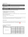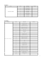
1
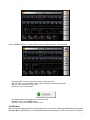
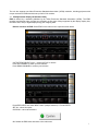
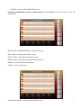
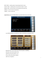
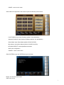
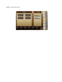
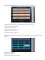
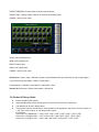
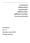
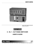
Owner´s Manual MX - 8000 80 x 80 Digital Modular Matrix Router Table of Contents CHAPTER ONE - PRODUCT OVERIEW .................................................................................................................... 3 1-1 SAFETY PRECAUTIONS ............................................................................................................................................ 3 1-2 W HAT’S IN THE BOX .................................................................................................................................................. 4 1-3 INTRODUCTION ........................................................................................................................................................ 4 1-4 PART NAMES & REFERENCE ..................................................................................................................................... 5 1-5 INSTALLATION GUIDLINES ......................................................................................................................................... 8 CHAPTER TWO - PRODUCT FEATURES ................................................................................................................ 8 2-1. SYSTEM OPERATION & CONFIGURATION DIAGRAM ..................................................................................................... 8 2-2 PRODUCT SPECIFICATIONS ....................................................................................................................................... 9 CHAPTER THREE - OPERATIONAL GUIDELINES ................................................................................................. 9 3-1 MAIN MENU USER GUIDE.......................................................................................................................................... 9 3-2 PRODUCT ID SET-UP GUIDE ................................................................................................................................... 18 3-3 RS-232C (COM PORT) SET-UP GUIDE.................................................................................................................. 18 CHAPTER FOUR - COMMUNICATION CODE CONFIGURATION ........................................................................ 19 4-1 CONFIGURATION OF RS-232C COMMUNICATION CODE ............................................................................................. 19 4-2 LAN COMMUNICATION CODE CONFIGURATION ......................................................................................................... 25 4-3 CONNECTOR PIN ASSIGNMENT ............................................................................................................................... 26 CHAPTER FIVE - WARRANTY INFORMATION ..................................................................................................... 28 RETURNS .................................................................................................................................................................. 28 2 1. PRODUCT OVERVIEW 1-1 SAFETY PRECAUTIONS • • • • • • • • • • All safety instructions should be read and understood before the unit is operated. The owner’s manual and safety instructions should be retained for future reference. Unplug this unit from the wall outlet before cleaning. Do not use liquid or aerosol cleaners. Use a damp cloth only. Keep away from wet, magnetic, and flammable surfaces or substances. Always use the correct external power supply (indicated on the product label) when operating this unit. This unit may be equipped with a 3 wire grounding-type plug - a plug having a third (grounding) pin. This pin will only fit in to a grounding type power outlet. If you are unable to insert the plug in to the outlet, contact your electrician to replace your obsolete outlet. Air vents should be kept clean and unobstructed at all times. Please refrain from using frayed power cords and damaged wall outlets. Do not place any heavy objects or equipment on top of the unit. To prevent electrical damage, TURN OFF the power to this unit before inserting or removing INPUT/OUTPUT slot cards. If you experience any problems while operating this unit, please contact our tech-support team at (201) 488-3232 or send us an inquiry at [email protected]. Declaration of Conformity According to Council Directive 73/23/EEC (February 19, 1973) on the Harmonization of the Laws of Member States relating to Electrical Equipment; Council Directive 89/336/EEC (May 3, 1989) on Electromagnetic Compatibility; Council Directive 93/68/EEC (July 22, 1993)Amending Directives 89/336/EEC (MC) and 73/23/EEC (Low Voltage Equipment Safety), and/or CPU Boards and Power Supplies used Council Directive 93/68/EEC with Matrix, Dtrovision, LLC., 286 Houses Corner Rd. Sparta, NJ 09871 973-383-4878, declares under sole responsibility, that the product identifies with 93/66/EEC of the Council Directive Low Voltage Equipment Safety. Each product marketed is identical to the representative unit tested and found to be compliant with the standards. 3 1-2 What’s in the Box • • • • Main Frame: MX-8000 Power Adapter RS-232C & LAN cables Owner’s Manual 1-3 Introduction The MX-8000 is the largest highest performance modular expandable matrix router in the world, with up to 80 inputs and 80 outputs for cross-platform DVI, HDMI, or 3G SDI switching within the same matrix. PureLink’s proprietary software is combined with a robust chassis design to make this router the most flexible and integrated routing solution for AV System Integrators ever made. Field-Upgradeable Modular Design: Because PureLink is truly modular, our matrix routers can be customized in different I/O sizes from 8×8 to 80×80 Non-Blocking Topology: Any input, HDMI, DVI or 3G-SDI (including HDCP protected sources,) can be tied to any or all outputs without limitation. One source can be viewed on multiple displays at the same time. Cross-Platform switching is done instantly with no frame delay or latency. PureLink Digital Matrix Routers feature the fastest response time in the world. Hybrid Architecture: Any type of input signal (fiber optical, DVI, HDMI or Cat5.) can be routed to any type of output connector (fiber optical, DVI, HDMI or Cat5.). Cross-Platform Design: Various combinations of I/O boards can be used in the same chassis at the same time. The matrix chassis provides interoperability between different types of boards. Redundant Power Supplies: MXA-1600, MXA-3200, and MX-8000 are equipped with N+1 redundant power supplies to ensure continuous 24/7 operation. In case of power supply failure, the supplies can be hot swapped. Control Options: Front panel buttons; RS-232 ; TCP/IP Ethernet; Built-in website. All frames are Vista Spyder, Barco Encore, Crestron, and AMX compatible. 4 1-4 Part Names & Reference <Front Panel> 1. 7” LCD Touch panel 2. Menu button 3. Power switch 4. Lock 5. Ventilation 4 1 2 3 5 5 <MX-8000 HDMI Type> 1. Control card 2. HDMI Input card 3. Ventilation 4. HDMI Output card 5. Power LED 6. AC power port 7. F.G. 8. Ventilation 6 <MX-8000 DVI Type> 1. Control card 2. DVI Input card 3. Ventilation 4. DVI Output card 5. Power LED 6. AC power port 7. F.G. 8. Ventilation 7 1-5 Installation Guidelines The following installation settings are recommended for optimal performance. • • • • Operational temperature should be 30° C or below Operational humidity should be 60% or below Operational environment should be dust-free and well ventilated Stabilized AC input power (AVR-based power supply) is highly advised 2. PRODUCT FEATURES 2-1. System Configuration Diagram Operation configuration diagram of the matrix is shown in following picture. Any of the input signals can be selected to each output port by front panel switch, external RS-232C or LAN. Any combinations of input signals can be selected at output side. FUNCTIONAL BLOCK DIAGRAM, DVI MULTIPLEXERS INPUT/OUTPUT CONNECTIONS, DVI MULTIPLEXERS 8 2-2 Product Specifications • • • • • • • • • • • • • Signal Type: TMDS signals, digital R.G.B. 2k HDMI Data Transmission Band: 2.25 Gbps (single link). DVI-D Data Transmission band: 1.65 Gbps (single link). HDMI version 1.3 with deep color 36 bits Resolution Range: VGA (640*480) ~ WUXGA (1900*1200)@60Hz, 480p~1080i/p. Panel: 7 inch touch panel, pressure recognition type Port switch control: Front LCD touch-panel, RS-232C port, LAN port. Input-output port: Input 80 / output 80 Input-output connector: DVI-D 29 pin Female or HDMI 19 pin Female Power source: AC 85~286VAC Internal power, Power consume: 300 Watts, Dimensions: (W x L x H) 440 x 294 x1250mm Weight: 16 kg. 3. OPERATIONAL GUIDELINES 3-1 Main Menu User-Guide 9 MX-8000 Front Panel Switches & Functions • Power Switch: turn power to the unit ON or OFF • System Check: troubleshoot when error messages appear • Reset: push button 3-4 seconds to reboot the unit • Touch Screen ON/OFF: turn the touch panel display ON or OFF • Back Light ON/OFF: turn touch panel backlight ON or OFF • RS-232: shows RS-232 communication status If matrix is switched ON, front touch panel shows internal set up status after initiation of the system. Then it shows main menu as follows. Touch Panel Display Main Menu • CREATE: set input/output channels • PREVIEW: preview the status of input/output channels or EDID set up • SYSTEM CONFIG: set up internal system • SYSTEM INFO: review the general status of the system • PRESET: save input/output channels to memory • EDID: retrieve and save the EDID data from displays To Select INPUT/OUTPUT Channels: Press CREATE on the main menu to open the screen in the figure below Press CHANNEL INPUT menu -> Select INPUT button Press UP CHANNEL to select up to 20 channels Press DOWN CHANNEL to reverse the selection 1 Press CHANNEL OUTPUT -> select OUTPUT button (multiple selection) -> Press ENTER Press CANCEL to cancel the set-up and return to the main menu ONE TO ONE: set up each INPUT channel with an OUTPUT channel automatically SET ALL: select all OUTPUTS at a time CLEAR ALL: cancel all selections OK: finalize channel set-up and return to the main menu PRESET SAVE -> start PRESET menu RETURN -> return to CHANNEL OUTPUT menu Set EDID Data Built-in Extended Display Identification Data (EDID) read & write function with Electrically Erasable Programmable Read-Only Memory (EEPROM), to save display EDID data while supporting any HDTV with maximum resolutions. 1 The unit also supports non-Video Electronics Standards Association (VESA) resolution, including projectors with unique resolutions. EDID should be set-up first for DVI monitors. **** EDID [Extended Display Identification Data] EDID is defined by a standard published by the Video Electronics Standards Association (VESA). The EDID includes manufacturer name, product type, phosphor or filter type, timings supported by the display, display size, luminance data, and (for digital displays only) pixel mapping data. Retrieve and Save of EDID: Select EDID on the main menu to open the screen below OUTPUT EDID SELECT menu -> select OUTPUT to retrieve Press UP CHANNEL to select up to 20 channels Press DOWN CHANNEL to reverse your selection Press EDID INPUT and select INPUT button (multiple selection) -> Press ENTER SET ALL: select all outputs CLEAR ALL: cancel all selections OK: finalize the EDID save and return to the main menu 1 RETURN -> return to INPUT EDID SELECT menu Previewing INPUT/OUTPUT channel or EDID selection: Select PREVIEW on the main menu to open the screen below: INPUT/OUTPUT CHANNEL PREVIEW -> initial screen view INPUT VIEW -> switching status based on input OUTPUT VIEW -> switching status based on output MATRIX VIEW -> shows input/output status at the same time ARROW -> move the screen in all directions CANCEL -> return to main menu Select EDID CHANNEL to open the EDID PREVIEW menu 1 INPUT VIEW -> switching status of inputs/outputs based on input OUTPUT VIEW -> switching status of inputs/outputs based on output MATRIX VIEW -> shows the status of inputs/outputs at the same time ARROW -> move the screen in all directions CANCEL -> return to main menu System Set-up: Select SYSTEM CONFIG to open the RS-232 set-up menu below: Use SYSTEM CONFIG to set up RS-232, LAN, and SYSTEM communications codes. Baud Rate: input communication speed of RS-232 (default: 19200BPS) DATA Bits: input data bits (default: 8 bit) Stop Bits: input stop bits (default: 1 bit) Parity: confirm parity (default: Disable) SAVE: save configuration 1 CANCEL: return to main menu Select LAN on the right side of the screen to open the LAN set-up menu below: Local IP Address: input local IP address (default: 192.168.000.002) Gateway IP Address: input Gateway IP Address (default: 192.168.000.001) Subnet Mask: input Subnet Mask (default: 255.255.255.255) Mac Address: set up Mac Address (default: 00.08.DC.00.00.00) HEX CHAR SELECT: select alphabet and numbers SAVE: save configuration CANCELL: return to main menu Select SYSTEM to open the SYSTEM set-up menu below: Buzzer: turn buzzer sound On/Off SAVE: save set-up 1 CANCEL: return to main menu 1 Preview of Channel and System set up: Select SYSTEM INFO to open the screen below. SYSTEM INFO screen displays the current status of channel selection and system set-up. RS232: view RS232 configuration status LAN: view LAN configuration status SYSTEM: view touch-sound set-up CHANNEL: view channel selection set-up Select CANCEL to return to the main menu. Preset set up: Select PRESET to open the screen below. The PRESET function saves up to 12 input and output channels. PRESET SELECT: select PRESET PRESET EDIT: edit PRESET PRESET NAME: edit saved number and name 1 PRESET PREVIEW: view the status of saved preset channels PRESET CALL: change current channels to channels of selected preset CANCEL: return to main menu CHAR: select character input NUM: select number input DELETE: delete input SAVE: save edited name CANCEL: return to main menu Preset Save: Create-> Input-> Select#-> Output-> Select Multiple ##->If you add more input go to Input again-> If you done all Input and Output ->Enter-> Preset Save-> Preset Number -> Select#-> Preset Name-> Input Name->Save Preset Call: Preset Call-> Select Preset Name-> Preset Call 3-2 Product ID Set-up Guide • • • • Product ID setting (DIP switch) When multiple matrix routers are being used, a product ID can be set for each router. The address can be set in binary values. The product number is the value set in deep switches of the equipment, and can be set in the values of 1 ~ 255. If the value is set as “0”, the channel will not work. For example; Product ID = 01 (00000001b) -- 1 ON, 2 OFF, 3 OFF, 4 OFF, 5 OFF, 6 OFF, 7 OFF, 8 OFF, Product ID = 10 (00001010b) -- 1 OFF, 2 ON, 3 OFF, 4 ON, 5 OFF, 6 OFF, 7 OFF, 8 OFF, Product ID = 23 (00010111b) -- 1 ON, 2 ON, 3 ON, 4 OFF, 5 ON, 6 OFF, 7 OFF, 8 OFF 1 D0 D1 D2 D3 D4 D5 D6 D7 LSB MSB **The default product ID for this unit is set to “1” at the time of delivery. 3-3 RS-232C (COM PORT) Set-up Guide After booting the MX-8000 matrix router, connect the RS-232C cable and configure the communication settings as follows: • • Execute DVI switch controller 3.0, MiniTerm.exe or hyper terminal. Communication setting: You may set port COM 1 ~ 4 or you may use all available ports. Baud rate: 19200, Data bit:8, Stop bit:1, Parity: None, Flow Control: None 4. COMMUNICATION CODE CONFIGURATION 4-1 Configuration of RS-232C Communication Code Programmer’s Guide (Code Structure and Examples) This section is designed for programmers who wish to create their own control programs using the command code. All PureLink digital matrix routers provide a simple character stream control used by external control devices attached to a PureLink device. Command codes are used primarily for control, during system installation and setup, and for diagnostic purposes. Overview Command code is a set of alphanumeric characters that combine to form control commands. Command code strings are entered into a terminal emulation program (such as windows HyperTerminal) running on an external control device. The control device (PC, third-party controller) sends the commands to the system. Control devices must be able to send and receive ASCII or HEXA code via an RS-232 or Ethernet port. Command Code Formats A command code is a series of command characters and numbers used to send commands to the system. Commands include basic formulas for creating and disconnecting switches, as well as for verifying the status of switches. In a command code, each character is either general command (e.g, C for connect) or an identifier that indicates what the following number designates (e.g, “O” and the number following it designate an “output number”). The command code *255CI01O01! Can be interested as follows: (*) Starting the command code (255) Router ID is 255 (C) Create connection on (I01) Input 01 to (O01) Output 01 (!) take the command. For a complete list of command characters and their functions, see page 32 Ack value (Acknowledge value: Response from PureLink device) will be echoed back to the terminal screen as the unit accepts them. When a command is successfully executed, all of the characters appear containing the character “s” which stands for status. For example, 1 Ex 1) Command (Connect Input 1 to Output 1) *255CI01O01! ↵ Ack value *255sC I01O01! Ex 2) Command (Check Input connection status on Output 3) *255?O03! ↵ Ack Value *255s? I03O03! General Rules for Command Codes The commands are coded in ASCII and HEXA. Please refer to Table 3.1 on pg. 32 for detailed descriptions of keys and functions. A basic command code setup is shown below; Ex) *255CI01O01! ↵ Start (*) + Router ID (255) + Command (C) + Input number (I01) + Output number (O01) + End (!) + Enter (↵) A command line allows execution of only one command. Multiple commands require execution of multiple strings; one command per string. All s begin with * (Start) byte. All s end with ! (End) byte. All s will be executed when ↵ (Enter) is entered. The correct Router ID must be entered in a command code. Systems will not react to the command if a wrong Router ID is entered. The Factory Default Router ID is set to 255 and the universal Router ID is 999. Systems will react to the command whenever universal Router ID is entered in command code. Command codes typically are not case-sensitive. To specify multiple inputs and outputs, enter a “,” (Comma) between numbers. (Ex., *255CI01O01,02,03! ↵ : Connects Input 01 to Output 01, 02, and 03) Use - (Hyphen) for range connection. (EX., *255CI01O01-04! ↵ : Connects Input 01 to Output 01,02,03, and 04) 2 Table 4.1 Command Codes Characters Tables The table below shows command code characters (keys), which are used to generate control commands, their functions, and short function descriptions. Key HEX 0x2A Function ASCII * Description and Example Byte Start the command Header Code 1 Tail Code 1 ↵ End the command Execute the command Execute the command 1 0x43 0x63 C c Connect (Video and Audio) 0x56,0x43 0x76,0x63 VC vc Connect (Video only) 0x41,0x43 0x61,0x63 AC ac Connect (Audio only) 0x3F ? 0x44 0x64 0x56,0x44 0x76,0x64 0x41,0x44 0x61,0x64 D d VD vd AD ad 0x21 ! 0D 0x49 0x69 Status Disconnect Disconnect (Video only) Disconnect (Audio only) , Space - Range I i Router ID check ?version Firmware check version 0x40 @ Baud rate setting 0x4E 0x6E N n Networking setting 0x48 0x68 H h Connection check Initiates a Connect (switch) command for both Video and Audio; this must precede input and output specification Initiates a Connect (switch) command for Video only; this must precede input and output specification Initiates a Connect (switch) command for Audio only; this must precede input and output specification Status command; this must precede input and output specification Disconnect command for both Video and Audio; this must precede input and output specification Disconnect command for Video only; this must precede input and output specification Disconnect command for Audio only; this must precede input and output specification Separates the numbers within entries that contain multiple numbers Specifies a range of numbers in entries containing multiple numbers Router ID check command; check router’s current ID number Firmware version check command; *255?version! ↵ Baud rate setting command; *255@001! ↵ 19200 *255@002! ↵ 38400 *255@003! ↵ 57600 *255@004! ↵ 115200 Network configuration setting command: - IP Setting *255NIP125.135.199.004! ↵ - Subnet Mask Setting *255NSM255.255.255.000! ↵ - Gate Way Setting *255NGW192.168.000.001! ↵ - MAC Address Setting *255NMA00.50.C2.B0.20.05! ↵ - Port Number Setting *255NPN3000! ↵ - Network Information *255NNI000! ↵ Router communication command: *255H000! ↵ connection check 1 2 2 1 1 2 2 1 1 1 1 1 2 Command Ack (Acknowledge) Value Response When command code s are entered into a terminal emulation program (such as HyperTerminal) and are accepted by the system, they respond back to the terminal screen one at a time, as noted below in the table. The complete command has executed successfully when all of the entered characters including “s” which stands for status, appear. If a command character is not accepted, a different character than the one entered appears and all or part of the command has not been executed. Ack (Acknowledge) Value Response Table The following table shows ack value response characters along with their descriptions and meanings, which may appear instead of the initially entered character or number. If these characters appear, all or part of the command has not been executed. Table 4.2 Descriptions of Acknowledge (ACK) Signals Ack value Description Input 1 is not connected No information in each channel. Command Code Error Indicates that system has rejected all or part of the command Router ID Error Indicates that the wrong ID number was entered Command Code Ack Value Examples Command Code Entered *255CI01O01! ↵ *255CO01! ↵ Ack Value as appears in the control program *255sC I01O01 ! Command Code Error *255CI01O01↵ Command Code Error *300CI01O01! ↵ Router ID Error Explanation of Result The command was successfully executed The command was not executed because the input number was not included The command was not executed because “!” (End) was not included The command was not executed because the actual Router ID and entered Router ID did not match 2 4.2 Connecting Switches A switch is an active connection between an input (source) signal and one or more output (display) devices. The signals connected in a switch command are either individual signals or groups of signals coming through the connectors on the rear of the unit. The “C” key initiates a Connect command for routing a switch. The characters and numbers that follow the “C” command tell the system, which inputs and outputs to connect. The last character “!” is found at the end of a command code which tells the system to execute the command. For example, the command code *255CI01O01! ↵ can be interpreted as follows: (*) Starting the command code (255) Router ID is 255 (C) Create connection on (I01) Input 01 to (O01) Output 01 (!) take the command. For a complete list of command characters and their functions, see page 21. To connect a switch: 1. Enter the Connect command below. Replace the “#”s with the input and output number(s). *255CI#O#!↵ Examples (Connect Video and Audio): Command Codes Action *255CI01O01! ↵ Connect Input 1 to Output 1 *255CI01O01,I02O02,I03O03! ↵ Connect Input 1 to Output 1, Input 2 to Output 2, and Input 3 to Output 3 Connect Input 1 to Output 1, 2, and 3 *255CI01O01-07! ↵ Connect Input 1 to Output 1, 2, 3, 4, 5, 6, and 7 *255CI01O08,I08O02! ↵ *255CI01O01,02,03! ↵ Examples (Connect Video only): Command Codes Connect Input 1 to Output 8 and Input 8 to Output 2 Action *255VCI01O01! ↵ Connect Input 1 to Output 1 *255VCI01O01,I02O02,I03O03! ↵ Connect Input 1 to Output 1, Input 2 to Output 2, and Input 3 to Output 3 Connect Input 1 to Output 1, 2, and 3 *255VCI01O01-07! ↵ Connect Input 1 to Output 1, 2, 3, 4, 5, 6, and 7 *255VCI01O08,I08O02! ↵ *255VCI01O01,02,03! ↵ Examples (Connect Audio only): Command Codes *255ACI01O01! ↵ Connect Input 1 to Output 8 and Input 8 to Output 2 Action Connect Input 1 to Output 1 2 *255ACI01O08,I08O02! ↵ Connect Input 1 to Output 8 and Input 8 to Output 2 *255ACI01O01,I02O02,I03O03! ↵ Connect Input 1 to Output 1, Input 2 to Output 2, and Input 3 to Output 3 Connect Input 1 to Output 1, 2, and 3 *255ACI01O01-07! ↵ Connect Input 1 to Output 1, 2, 3, 4, 5, 6, and 7 *255ACI01O01,02,03! ↵ 4.3 Disconnecting Switches The characters and numbers in a Disconnect command tell the system which input or output to disconnect. The “D” key initiates a Disconnect command for routing a switch. The characters and numbers that follow the “D” command tell the system that inputs and outputs to disconnect. The last character “!” is found at the end of the Command code, which tells the system to execute the command. For example, the command code *255DI01O00! ↵ can be interpreted as follows: (*) Starting the command code (255) Router ID is 255 (D) Disconnect on (I01) Input 01 to (O00) Output 00 (!) take the command. For a complete list of command characters and their functions, see page 33 . 1. Enter the Disconnect command below. Replace the “#”s with the input and output number(s). *255DI#O#! ↵ Examples (Disconnect Video and Audio): Command Codes *255DI01O00! ↵ *255DI00O03,04,05! ↵ *255DI00O03-06! ↵ *255DALLIO! ↵ Action Disconnect Input 1 to no Output (00) Disconnects Outputs 3, 4, and 5 Disconnects output 3, 4, 5, and 6 Disconnects all inputs and outputs Examples(Disconnect Video only): Command Codes Action Disconnect Input 1 to no Output (00) *255VDI01O00! ↵ Disconnects Outputs 3, 4, and 5 *255VDI00O03,04,05! ↵ Disconnects output 3, 4, 5, and 6 *255VDI00O03-06! ↵ Disconnects all inputs and outputs *255VDALLIO! ↵ Examples(Disconnect Audio only): Command Codes *255ADI01O00! ↵ *255ADI00O03,04,05! ↵ *255ADI00O03-06! ↵ *255ADALLIO! ↵ Action Disconnect Input 1 to no Output (00) Disconnects Outputs 3, 4, and 5 Disconnects output 3, 4, 5, and 6 Disconnects all inputs and outputs 4.4 Connection Status Check A connection status can be checked to confirm that the switch has been correctly executed or to confirm correct routing to multiple outputs. The characters and numbers in a status command tell the system which input or output to check. 1. Enter the Connection status check command below. Replace the “#”s with the input and output number(s). 2 *255?I#!↵ or *255?O#!↵ Examples: Command Codes *255?I01! ↵ *255?O07! ↵ *255?ALLIO! ↵ Action Check Output connection status on Input 1 Check Input connection status on Output 7 Check all Input and Output connection status 4.5 Router ID Check User can confirm the router’s Current ID setting. Universal Router ID is 999 Example: Command Codes *999I000! ↵ Action Check Router’s ID 4.6 Firmware Version Check User can confirm router’s current firmware version. Example: Command Codes Action Check Router’s Firmware version *999?version! ↵ 4.7 Baud Rate Setting User can set baud rate for RS-232 command control. 1. Enter the Baud rate setting command below. Replace the “#”s with the input and output number(s). *255@#! ↵ @001: Baud rate at 19200 @002: Baud rate at 38400 @003: Baud rate at 57600 @004: Baud rate at 115200 Example: Command Code s *255@001! ↵ *255@002! ↵ *255@003! ↵ *255@004! ↵ Action Set baud rate at 19200 Set baud rate at 38400 Set baud rate at 57600 Set baud rate at 115200 Network Configuration: User can check and set network configuration for LAN control. Examples: Command Code s Action Check current Network Information *255NNI000! ↵ Set IP address at 125.135.199.004 *255NIP192.168.000.004! ↵ Set Subnet Mask at 255.255.255.000 *255NSM255.255.255.000! ↵ Set Gate Way at 192.168.000.001 *255NGW192.168.000.001! ↵ *255NMA00.00.C2.B0.20.05! ↵ Set Mac Address at 00.00.C2.B0.20.05 Set Port Number at 3000 *255NPN3000! ↵ 2 Connection Checking: User can check the connection status. Example: Command Code s Action Check connection status *255H000! ↵ Function Key On/Off: User can enable or disable the function key located on physical router’s front panel. Example: Command Code s Action Function key On/Off *255K000! ↵ RS232 Cable Pin#2#3 crossed, should test use cable at box (included) 4-2 LAN Communication Code Configuration 1. Switching by explorer: Command set sent to web server (matrix router) for switching Begin with a character train of “LCD.CGI”, “O 01 = I 01means “Output 01 Input 01”. The sequence and size of the character train should be the same. Reset the router to establish a connection to the server. Channel Change http://192.168.0.2/LCD.CGI?O01=I01&O02=I02&O03=I03&O04=I04&O05=I05&O06=I06&O07=I07&O08=I08&O09=I 09&O10=I10&O11=I11&O12=I12&O13=I13&O14=I14&O15=I15&O16=I16&O17=I17&O18=I18 O19=I19&O20=I20&O21=I21&O22=I22&O23=I23&O24=I24&O25=I25&O26=I26&O27=I27&O28=I28&O29=I29&O30 =I30&O31=I31&O32=I32&O33=I33&O34=I34&O35=I35&------&O80=I80&Submit_=SEND Initialization (Reset) http://192.168.0.2/LCD.CGI?O01=I01&O02=I02&O03=I03&O04=I04&O05=I05&O06=I06&O07=I07&O08=I08&O09=I 09&O10=I10&O11=I11&O12=I12&O13=I13&O14=I14&O15=I15&O16=I16&O17=I17&O18=I18 O19=I19&O20=I20&O21=I21&O22=I22&O23=I23&O24=I24&O25=I25&O26=I26&O27=I27&O28=I28&O29=I29&O30 =I30&O31=I31&O32=I32&O33=I33&O34=I34&O35=I35&----&O80=I80&Submit_=Reset 4-3 Connector Pin Assignment RS-232C INPUT Part No. D-SUB 9 Pin Connector Pin No. Description 1 Not used 2 Rx D 3 Tx D 4 Not used 5 GND 6 Not used 7 Not used 8 Not used 9 Not used Remarks 2 LAN INPUT Part No. Pin No. Description 1 Transmit data (+) 2 Transmit data (-) 3 Receive data(+) 4 Not used 5 Not used 6 Receive data(-) 7 Not used 8 Not used Remarks RJ-45 8 Pin Connector DVI-D INPUT Part No. DVI-D 29 Pin Connector Pin No. Description 1 TMDS DATA 2M 2 TMDS DATA 2P 3 TMDS DATA 2/4 Shield 4 TMDS DATA 4M(N.C) 5 TMDS DATA 4P(N.C) 6 DDC Clock 7 DDC Data 8 N.C 9 TMDS DATA 1M 10 TMDS DATA 1P 11 TMDS DATA 1/3 Shield 12 TMDS DATA 3M(N.C) 13 TMDS DATA 3P(N.C) 14 5V 15 GND 16 Hot Plug Detect 17 TMDS DATA 0M 18 TMDS DATA 0P 19 TMDS DATA 0/5 Shield 20 TMDS DATA 5M(N.C) 21 TMDS DATA 5P(N.C) 22 TMDS DATA Clock Shield 23 TMDS Clock P 24 TMDS Clock M 25~29 N.C Remarks 2 5. Warranty Information Manufacturer’s Warranty (2-Years) PureLink warrants this MX -8000 modular matrix router to be free from defects in workmanship and materials, under normal use and service, for a period of two (2) year from the date of purchase from Dtrovision or its authorized resellers. If the product does not operate as warranted during the applicable warranty period, PureLink shall, at its option and expense, execute one of the following as necessary: 1. Repair the defective product or part 2. Deliver to customer and equivalent product or part to replace the defective item 3. Refund to customer the purchase price paid for the defective product All products that are replaced become the property of PureLink. Replacement products may be new or reconditioned. Repaired or replacement products or parts come with a 90-day warranty or the remainder of the warranty period. PureLink shall not be responsible for any software, firmware, information, or memory data loss of contained in, stored on, or integrated with any products returned to PureLink for repair under warranty. Customer Service Any customer service inquiries can be submitted electronically through the Q&A form on our website (www.purelink.de ). For immediate assistance please contact us at +49 (0) 5971- 800 299-0 to reach our customer care or tech support team. PureLink GmbH Hovesaatstraße 6 D-48432 Rheine Telefon: +49 (0) 5971 800 299-0 Fax: +49 (0) 5971 800 299-99 E-mail: [email protected] www.purelink.de For order support, please contact your local dealer. For technical support, please contact us at [email protected] 2 PureLink GmbH Hovesaatstraße 6 D-48432 Rheine Telefon: +49 (0) 5971 800 299-0 Fax: +49 (0) 5971 800 299-99 E-mail: [email protected] www.purelink.de For order support, please contact your local dealer. For technical support, please contact us at [email protected]