1
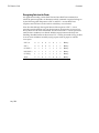
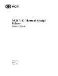
7193 Thermal Receipt Printer
Owner's Guide
On
Lin
e
pe
Pa
ut
rO
pe
Pa
7193-D100-V001
ee
rF
d
It is the policy of Axiohm IPB to improve products as new technology, components,
software, and firmware become available. Axiohm IPB, therefore, reserves the right to
change specifications without prior notice.
All features, functions, and operations described herein may not be marketed by Axiohm
IPB in all parts of the world. In some instances, photographs are of equipment prototypes.
Therefore, before using this document, consult your Axiohm IPB representative or office
for information that is applicable and current.
Copyright © 1993, 1996 by Axiohm IPB
Ithaca, New York USA
All Rights Reserved
Printed in USA
Confidential, Unpublished
Property of Axiohm IPB
Axiohm IPB is the name and mark of Dardell Technologies. NCR is the name and mark of
AT&T Global Information Solutions. AT&T Global Information Solutions is the name and
mark of AT&T. Epson is the name and mark of Seiko Epson Corporation.
Federal Communications Commission (FCC)
Radio Frequency Interference Statement
Warning
This equipment generates, uses, and can radiate radio frequency energy and if not
installed and used in accordance with the instructions manual, may cause interference to
radio communications. It has been tested and found to comply with the limits for a Class
A computing device pursuant to Subpart J of Part 15 of FCC Rules, which are designed to
provide reasonable protection against such interference when operated in a commercial
environment. Operation of this equipment in a residential area is likely to cause
interference in which case the user at his own expense will be required to take whatever
measures may be required to correct the interference.
Information to User
This equipment must be installed and used in strict accordance with the manufacturer's
instructions. However, there is no guarantee that interference to radio communications
will not occur in a particular commercial installation. If this equipment does cause
interference, which can be determined by turning the equipment off and on, the user is
encouraged to contact Axiohm immediately.
The Axiohm IPB company is not responsible for any radio or television interference
caused by unauthorized modification of this equipment or the substitution or attachment
of connecting cables and equipment other than those specified by Axiohm IPB. The
correction of interferences caused by such unauthorized modification, substitution or
attachment will be the responsibility of the user.
7193 Owner’s Guide
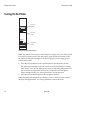
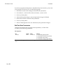
Quick Reference
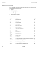
Quick Reference
This Quick Reference will direct you to key areas of the Owner's Guide. For a
complete listing of topics, see the Contents or Index.
Ordering Paper and Supplies
page 4
Information on where and how to obtain paper and optional items.
Setting Up the Printer
page 9
Basic requirements for unpacking and installing the printer.
Loading and Changing Paper
page 19
A brief discussion of the simple paper loading procedure.
Testing the Printer
page 23
Procedures for running a test to check the print quality of the printer.
Solving Problems
page 29
What to do if a problem occurs.
Diagnostics
page 33
A technical discussion of the three levels of diagnostics available.
Communication Interfaces
page 45
Specifications for the RS-232 and Parallel communication interfaces.
Commands
page 63
Lists and descriptions of the programming commands.
Specifications
page 101
Technical specifications for the printer.
May 1996
i
Quick Reference
7193 Owner’s Guide
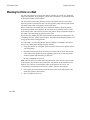
How to Use This Book
Use this book as an installation guide for setting up and preparing the printer to
run, as a training guide for teaching users how to operate the printer, or as a
reference for programming the host system to communicate with the printer. In
addition, information is also provided about the character sets and graphics that
are available. The book is divided into chapters that relate to each of these areas.
See the Quick Reference, Contents, or Index for detailed listings.
Who Should Use this Book?
This book is intended as a general guide for operators and supervisors who need
to know how to set up and use the printer. It is also intended as a technical guide
for programmers and system integrators who need to know the technical
information about the printer's communication and the programming commands
used by the host system to control the functions of the printer.
How to Obtain More Information
For more information about the 7193 printer and to order the following
documentation, please contact your Axiohm supplier:
ii
•
7193 Thermal Receipt Printer: Service Guide (7193-D200-V001)
Service and disassembly procedures (you must be a trained service
representative to service the printer)
•
Parts Information Manual (7193-D300-V001)
May 1996
7193 Owner’s Guide
Contents
Contents
About the 7193 Printer .......
1
Models ..................................................................................................................2
Communication Interfaces ...........................................................................2
Options...........................................................................................................2
Features.................................................................................................................2
Thermal Printhead ...............................................................................................3
Ordering Paper and Supplies..............................................................................4
Ordering Thermal Paper...............................................................................4
Ordering the Power Supply and Cables......................................................6
Ordering the Printer Wall-Mount Kit..........................................................6
Ordering Cash Drawers................................................................................6
Cleaning the Printer .............................................................................................7
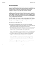
Setting Up the Printer.........
9
What Is in the Box? ..............................................................................................9
Removing the Packing Material ...................................................................9
Repacking the Printer..................................................................................10
Choosing a Location ..........................................................................................11
Setting Switches .................................................................................................12
Attaching the Feet ..............................................................................................14
Connecting Cash Drawer Cables ......................................................................15
Connecting Communication and Power Cables..............................................16
RS-232C Models ..........................................................................................16
Parallel Models ............................................................................................17
Turning On the Printer ......................................................................................18
Loading and Changing Paper ...........................................................................19
When to Change the Paper.........................................................................19
Removing the Paper Roll ............................................................................20
Putting In the Paper Roll ............................................................................21
Advancing Paper.........................................................................................22
May 1996
i
Contents
7193 Owner’s Guide
Testing the Printer ............................................................................................. 23
Mounting the Printer on a Wall ........................................................................ 25
Mounting the Power Supply on a Wall............................................................ 27
Solving Problems...............
29
Operator Panel Lights........................................................................................ 29
Correcting Problems.......................................................................................... 30
Operator-Correctable Conditions .............................................................. 30
Service-Related Problems........................................................................... 30
Contacting a Service Representative ......................................................... 31
Diagnostics........................
33
Level 0 Diagnostics ............................................................................................ 33
Level 1 Diagnostics ............................................................................................ 34
Setting Data Error and Data Buffer options ............................................. 35
Setting Printhead Resistance ...................................................................... 36
Setting Default Lines per Inch.................................................................... 37
Setting Partial Cut Distance ....................................................................... 38
Ignoring/Using the Carriage Return......................................................... 39
Running the Data Scope Mode .................................................................. 40
Testing Receipt Printing ............................................................................. 42
Level 2 Diagnostics ............................................................................................ 43
Level 3 Diagnostics ............................................................................................ 43
Communication .................
45
Communication Overview................................................................................ 45
Interfaces...................................................................................................... 45
Sending Commands.................................................................................... 45
RS-232C Interface............................................................................................... 46
XON/XOFF Protocol .................................................................................. 47
DTR/DSR Protocol ..................................................................................... 47
RS-232C Technical Specifications............................................................... 48
Parallel Interface ................................................................................................ 52
Parallel Protocol .......................................................................................... 52
Parallel Technical Specifications ................................................................ 53
ii
May 1996
7193 Owner’s Guide
Contents
Commands ........................
57
Command List....................................................................................................57
Printer Function Commands ......................................................................58
Print Characteristics Commands ...............................................................60
Graphics Commands ..................................................................................61
Printer Status Commands...........................................................................61
Real Time Commands.................................................................................62
Bar Code Commands..................................................................................62
Command Descriptions.....................................................................................63
Printer Function Commands ......................................................................63
Print Characteristics Commands ...............................................................73
Graphics Commands ..................................................................................79
Printer Status Commands...........................................................................84
Real Time Commands.................................................................................87
Bar Code Commands..................................................................................98
Appendix A: Specifications.
101
Features.............................................................................................................101
Reliability..........................................................................................................101
Power Requirements........................................................................................102
Environmental Conditions ..............................................................................102
Dimensions and Weight ..................................................................................103
Printing Specifications .....................................................................................103
Print Zones .......................................................................................................104
Density of Receipt Print Lines.........................................................................105
Duty Cycle Restrictions (Printing Solid Blocks) ............................................105
Appendix B: Print Characteristics
107
Index .................................................................................................................111
May 1996
iii
7193 Owner’s Guide
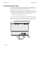
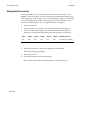
About the 7193 Printer
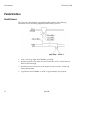
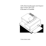
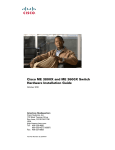
About the 7193 Printer
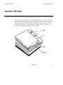
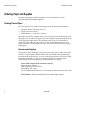
The 7193 thermal receipt printer is fast (at 600 lines per minute), quiet, and very
reliable. With thermal printing technology, there is no ribbon cassette to change,
and paper loading is extremely simple. The printer is small enough to fit almost
anywhere and is easy to use with the receipt exiting from the top. There is no
journal as it is kept electronically by the host system.
Operator
Panel
On
Lin
e
pe
Pa
ut
rO
pe
Pa
ee
rF
d
Cover
Receipt
Paper
Tear Off
Blade/ Knife
May 1996
1
About the 7193 Printer
7193 Owner’s Guide
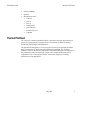
Models
There are several models of the 7193 depending on the communication interface
and the combination of options selected.
Communication Interfaces
•
RS-232C
•
Parallel
See the “Communication” chapter later in this book for more information.
Options
The following options are available:
•
Paper cutter
•
Cash drawer drivers: will open a separately purchased cash drawer under
software command
•
Wall-mount kit for hanging the printer on a wall (see “Setting Up the Printer”
later in this book)
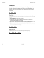
Features
All models come with the following features:
2
•
Remote power supply with wall-mount kit (see “Setting Up the Printer” later
in this book)
•
Drop-in paper loading which does not require using a spindle or threading
the paper through a paper path
•
Host-selectable 44 or 56 columns of print on 80 mm wide “fax grade” thermal
paper
•
600 print lines per minute
•
Two resident selectable character sets:
• PC Code Page 437 (US)
• PC Code Page 850 (Multilingual)
•
16K RAM available for downloadable character sets and bit-mapped graphics
•
4K buffer
May 1996
7193 Owner’s Guide
About the 7193 Printer
•
History EEROM
•
Speaker
•
Resident bar codes
• Code 39
• UPC-A
• UPC-E
• JAN8 (EAN)
• JAN13 (EAN)
• Interleaved 2 of 5
• Codabar
Thermal Printhead
The 7193 uses a thermal printhead which is extremely fast and quiet. Because it
uses heat to print directly on paper, there is no cassette or ribbon to change,
eliminating soiled fingers and paper dust.
The printhead is designed for a very long life, but it may be replaced if needed.
Only a trained service technician may replace the printhead. See “Solving
Problems” later in this book to determine if the printhead needs to be replaced. If
the printhead needs to be replaced, contact your Axiohm authorized service
organization. See “Cleaning the Printer” later in this chapter for cleaning
instructions for the printhead.
May 1996
3
About the 7193 Printer
7193 Owner’s Guide
Ordering Paper and Supplies
Thermal receipt paper and other supplies can be ordered from several
recommended and qualified suppliers.
Ordering Thermal Paper
The 7193 requires “fax grade” thermal paper with the following dimensions:
•
Diameter: 80 mm maximum (3.15 in.)
•
Length: 83 meters (273 ft.)
•
Width: 80 mm ± .5 mm (3.15 ± .008 in.)
The paper must not be attached at the core or the printer will be damaged when
the paper runs out. When the paper runs out, the printer stops printing and turns
on the Paper Out light (red) on the operator panel. There is no indication or
automatic signal when the paper runs low. It is recommended that you use a
paper roll with a colored stripe at the end of the roll to indicate that the paper is
running low.
Recommended Suppliers
The grades of paper listed here will give the best print quality. When more than
one stock or paper grade number is listed, the first number (standard density)
provides better image density. You may order paper directly from AT&T Global
Information Solutions. Contact your Axiohm supplier for ordering paper
manufactured by Kanzaki (paper grades listed on the next page).
AT&T Global Information Solutions Company
Media Products Division
9995 Washington Church Road
Miamisburg, OH 45342
Voice: 1(800)543-8130 (toll free), or local listing of Media Products sales office
Stock numbers: 878559 (standard density), 856966 (light density)
4
May 1996
7193 Owner’s Guide
About the 7193 Printer
Kanzaki Specialty Papers
In U.S. A.
Imaging Products
Voice: 1(413)736-3216, 1(800)628-8386 (toll free)
Fax: 1(413)731-8864
Paper grade: F380 (standard density), F180 (light density)
In Japan:
New OJI Paper Co., Ltd.
Voice: (03)3563-4763
Fax: (03)3563-1136
Paper grade: KF-740-2EX (standard density), KF-740-1EX (light density)
In Germany:
Kanzan Spezialpapiere GMBH
Voice: 011 49 2421 5924 20
Paper grade: KF-60 (standard density), KF-50 (light density)
Other Qualified Suppliers
The following companies manufacture thermal receipt paper which has been
tested with the 7193 and may be used if desired. Contact your Axiohm supplier
for further information.
Appleton Papers, Inc.
Voice: 1(414) 734-9841
Paper grade: T1012
Arjo-Wiggins Thermal Papers, Ltd.
Voice: 44 (0) 522 681212
Fax: 44 (0) 522 690972
Paper grade: S552, S662
Nippon Paper Industry Co., Ltd.
Business Communication Paper Division
Voice: (03)3218-8049
Fax: (03)3216-1397
Paper grade: TP50 KS
May 1996
5
About the 7193 Printer
7193 Owner’s Guide
Ordering the Power Supply and Cables
Contact your Axiohm supplier to order the power supply and cables. The
Axiohm numbers are for reference only. Suppliers may use different numbers.
•
Power supply with attached cable (to printer)
and wall-mount kit:
7193-F301
•
Separate power supply cord (to outlet)
Order for appropriate power connector
• United States:
7193-F320
• International:7193-F321
• United Kingdom:
7193-F322
• S.E.V.:
7193-F323
• Australia:
7193-F324
• Japan:
7193-F325
•
Communication cables
• RS-232C 25-pin (host) to 9-pin:
1420-C001-0030 (3 meters—9.8 ft.)
• RS-232C 9-pin to 9-pin:
1416-C057-0030 (3 meters—9.8 ft.)
• Parallel 25-pin to 25-pin:
1420-C003-0030 (3 meters—9.8 ft.)
Ordering the Printer Wall-Mount Kit
Contact your Axiohm supplier to order the printer wall-mount kit. The Axiohm
number below is for reference only. Other suppliers may use a different number.
Printer wall-mount kit:
7193-K260-V001
Ordering Cash Drawers
The following cash drawers may be used with the 7193 printer:
6
•
AT&T Global Information Solutions
(NCR Cash Drawer):
Model 7052-K657
•
M-S Cash Drawer Corp.:
Model EP-125 K series,
EP-127, EP-102
•
APG Cash Drawer:
Model 237
•
Indiana Cash Drawer:
Model SLD
May 1996
7193 Owner’s Guide
About the 7193 Printer
Cleaning the Printer
There is no customer maintenance required for the 7193. However, you may
occasionally clean the cabinet as needed to remove dust and finger marks. Use
any household cleaner designed for plastics, but test it first on a small unseen
area. The cabinet materials and finish are durable and are resistant to the
following items:
•
Cleaning solutions
•
Lubricants
•
Fuels
•
Cooking oils
•
Ultraviolet light
If the receipt paper bucket is dirty, wipe it with a clean, damp cloth.
Caution: Do not spray or try to clean the thermal printhead or the inside of the
printer with any kind of cleaner as this may damage the thermal printhead and
the electronics.
If the printhead appears dirty, wipe it with cotton swabs and rubbing alcohol. If
spotty or light printing problems persist after cleaning the thermal printhead, see
“Solving Problems” later in this book.
Note: The thermal printhead does not normally require cleaning if the
recommended paper grades are used. If non-recommended paper has been used
for an extended period of time, cleaning the printhead with cotton swabs and
rubbing alcohol will not be of much benefit. See “Recommended Suppliers”
earlier in this chapter for the recommended paper grades.
May 1996
7
7193 Owner’s Guide
Setting Up the Printer
Setting Up the Printer
What Is in the Box?
The following items are packed in the shipping box:
•
Printer enclosed in a plastic bag and foam pack
• Thermal paper roll, wrapped with a foam strip (inside printer)
• Test printout protecting the printhead (inside printer)
•
7193 Setup and User's Guide
•
Rubber feet and hook and loop fasteners (fasteners used to anchor printer)
•
Power supply with attached cable (to printer) and related items
• Power cord (from power supply to outlet)
• Wall-mount holder for the power supply with screws and wall anchors
• Tie-wrap for cable
These items may be ordered as options and will be shipped separately:
•
Wall-mount kit for the printer
•
Communication cable (from host system to printer)
•
Cash drawer with cables (see “Ordering Cash Drawers” on page 6)
Removing the Packing Material
May 1996
1.
Remove the printer from the foam pack and open the receipt cover by pulling
up on the front left corner.
2.
Remove the paper roll and test printout from inside the printer.
3.
Remove the foam strip from around the paper roll.
4.
Save all packing materials for future storing, moving, or shipping the printer.
Setting Up the Printer
7193 Owner’s Guide
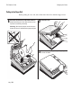
Repacking the Printer
1.
Protect the printhead by placing a piece of receipt paper between the receipt
cover and the printhead.
2.
Place the printer in the plastic bag and foam pack.
3.
Place the packed printer in the box and secure the box with packing tape.
4.
If you are sending the printer in for repair, call Axiohm IPB for a Return
Authorization Number at (607)274-2402.
Be prepared to answer questions concerning shipping and billing.
5.
After you have received a Return Authorization Number, send the printer to
the following address:
Axiohm IPB
950 Danby Road
Ithaca, NY 14850
U.S.A.
10
May 1996
7193 Owner’s Guide
Setting Up the Printer
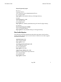
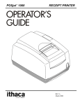
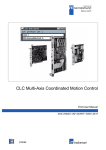
Choosing a Location
The 7193 is compact and requires little counter space. It may even be mounted on
a wall if space is at a premium. See “Mounting the Printer on a Wall” later in this
chapter. The power supply may also be mounted on a wall or under a table. See
“Mounting the Power Supply on a Wall” later in this chapter. Be sure to plan for
the length of the communication and power cables when choosing a location.
Make sure there is enough room to open the receipt cover and change the paper.
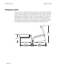
The following illustration shows the actual dimensions of the printer, but leave
several inches around the printer for connecting and accessing the cables.
225 mm
(8.85 in.)
119 mm
(4.69 in.)
165 mm
(6.50 in.)
May 1996
187 mm
(7.35 in.)
Setting Up the Printer
7193 Owner’s Guide
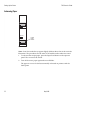
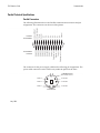
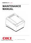
Setting Switches
A group of switches, called DIP switches, located on the bottom of the 7193 is
used for the following purposes:
•
To set variables for several printer functions (see the sections for the various
printer functions in “Level 1 Diagnostics” in the “Diagnostics” chapter)
•
To perform diagnostic tests (see the sections for the various diagnostic tests
in “Level 1 Diagnostics” in the “Diagnostics” chapter)
•
To set communication parameters for the RS-232C communication interface
(see “RS-232C Switch Settings” in the “Communication” chapter)
•
To set the data buffer for the Parallel communication interface (see “Parallel
Switch Settings” in the “Communication” chapter)
Caution: The DIP switches are set at the factory to predetermined settings and
should generally not be changed. If you must change the settings do so carefully
to avoid changing other functions.
Before changing any of the switches, first run the print test to print out the
current switch settings on the receipt. See “Testing the Printer” later in this
chapter for instructions on running the print test and for a sample printout.
Note: Switch #1 is used to toggle between regular communication with the host
system and Level 1 Diagnostics (used for the printer functions and level 1
diagnostic tests) as described below:
•
Switch #1 set to OFF: printer is ready to communicate with the host system
and receive data (online mode)
•
Switch #1 set to ON: printer is in Level 1 Diagnostics (setup mode)
If you want the printer to communicate with the host system, be sure switch 1 is
OFF. Use a paper clip or other pointed object to set the switch.
For additional information on the setup mode (Level 1 Diagnostics), see the
“Diagnostics” chapter.
Note: Some 7193 models may appear slightly different than what is shown in the
illustration. The procedures are the same for all models unless otherwise noted.
12
May 1996
7193 Owner’s Guide
May 1996
Setting Up the Printer
Setting Up the Printer
7193 Owner’s Guide
Attaching the Feet
Use the hook and loop fasteners to anchor the printer to a flat surface; be sure the
surface is clean and dry. Use the rubber pads if you are mounting the printer on
the wall. See “Mounting the Printer on a Wall” later in this chapter.
Note: Some 7193 models may appear slightly different than what is shown in the
illustration. The procedures are the same for all models unless otherwise noted.
Slots for
Rubber Pads
or Hook & Loop
Fasteners
Bottom of Printer
1.
Remove the paper from the adhesive on the back of the pads or loop
fasteners and affix them in the slots on the bottom of the printer.
2.
Attach the hook fasteners to the loop fasteners (if used).
This will save you having to apply the hook fasteners separately and trying to
match them to the loop fasteners on the printer.
3.
14
Remove the paper from the adhesive on the back of the hook fasteners and
place the printer firmly on the selected surface.
May 1996
7193 Owner’s Guide
Setting Up the Printer
Connecting Cash Drawer Cables
The cash drawer option allows up to two cash drawers to be connected to the
printer in a system with a PC that has no connectors for the cash drawer cables.
The cash drawer cables usually come with the cash drawer.
The cash drawers are operated by software command from the host system
through the printer. For additional information on the printer commands used by
the host system to activate the cash drawers, see “Commands” later in this book.
1.
Plug the cash drawer cables into the connectors on the printer.
The connectors are standard phone connectors.
2.
If only one cash drawer is used, plug the cable into the connector labeled 1.
Note: Some 7193 models may appear slightly different than what is shown in the
illustration. The procedures are the same for all models unless otherwise noted.
1
Communications
Cable Slot
Back View of Printer
May 1996
2
Cash Drawer
Connectors
Power Supply
Cable Slot
Setting Up the Printer
7193 Owner’s Guide
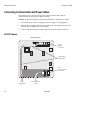
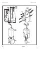
Connecting Communication and Power Cables
The printer receives power from a power supply and uses one cable for
communication and a separate cable for power.
Caution: Be sure that all power is disconnected before connecting the cables.
1.
Turn off the host system or unplug the power supply if it is plugged in.
2.
Plug the power supply cable into the printer first, then plug the power cord
into the power supply, then into an outlet.
3.
Connect the communication cable to the printer, then to the host system.
RS-232C Models
Bottom of Printer
Power
Supply
Connector
Power Supply
Cable Route
9-Pin
Communication
Connector
Power
Supply Cable
16
Communication
Cable
May 1996
7193 Owner’s Guide
Setting Up the Printer
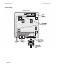
Parallel Models
Bottom of Printer
Power
Supply
Connector
Power Supply
Cable Route
2
Power
Supply Cable
1
Cash Drawer
Drivers
25 Pin Female
Communication
Connector
25-pin Parallel
Communication
Cable
May 1996
Setting Up the Printer
7193 Owner’s Guide
Turning On the Printer
On Line
Button
On Line
On Line
Light
Paper Out
Paper Out
Light
Paper Feed
Operator Panel (Remote Printer)
Note: The printer receives power when the power supply is on even if the printer
is off-line. To remove power from the printer, press the On Line button to take
the printer off-line (On Line light is off), then unplug the power supply power
cord from the outlet.
1.
Press the On Line button on the operator panel to put the printer on-line.
The printer goes through a self-test routine to ensure everything is working,
then “beeps.” The On Line light (green) comes on indicating the printer is online. If the On Line light does not come on, or either the On Line light or
Paper Out light flashes, see “Solving Problems” later in this book.
2.
Press the On Line button again to take the printer off-line.
When the printer has completed its “startup” cycle it is ready to receive data. If
the Paper Out light flashes, see “Solving Problems” later in this book.
18
May 1996
7193 Owner’s Guide
Setting Up the Printer
Loading and Changing Paper
The 7193 features extremely simple paper loading. See the next two pages for
detailed illustrations.
If you are loading paper for the first time and have already taken the roll out, go
to “Putting In the Paper Roll” later in this chapter. If you have not taken the roll
out, continue with the following instructions. Although the illustrations show a
used roll being removed, the instructions still apply to loading paper for the first
time.
When to Change the Paper
You will need to change the paper when you see a colored stripe on the receipt
paper or when the Paper Out light (red) on the operator panel turns on.
•
Paper Low Stripe
When the paper low stripe appears on receipts being printed, change the
paper as soon as possible to avoid running out of paper part way through a
transaction.
•
Paper Out light
When the Paper Out light (red) on the operator panel comes on, the paper is
completely out. Do not run a transaction without paper: the data may be lost.
Caution: Do not operate the printer or host system if the printer runs out of
paper. The printer will not operate without paper, but it may continue to accept
data from the host system. Because the printer cannot print any transactions, the
data may be lost.
May 1996
Setting Up the Printer
7193 Owner’s Guide
Removing the Paper Roll
20
May 1996
7193 Owner’s Guide
Setting Up the Printer
Putting In the Paper Roll
Before putting in a new roll, tear off the end of the roll so that the edge is loose.
1
Place the roll into the bin with a few inches of
paper extending over the cabinet front (or top,
if printer is vertically mounted).
2
Close the cover.
3
Remove the excess paper by tearing it against
the tear off blade.
Warning: Be sure the paper unrolls from the
bottom of the roll. Otherwise the paper will jam.
On
e
Lin
ut
rO
pe
Pa
d
ee
rF
pe
Pa
On
e
Lin
p
Pa
er O
ut
pe
Pa
May 1996
ee
rF
d
Setting Up the Printer
7193 Owner’s Guide
Advancing Paper
On Line
Paper Out
Paper
Feed
Button
Paper Feed
Operator Panel
Note: Some 7193 models may appear slightly different than what is shown in the
illustration. The procedures are the same for all models unless otherwise noted.
1.
To advance the receipt paper, press the Paper Feed button on the operator
panel. The cover must be closed.
2.
Tear off the excess paper against the tear off blade.
The paper is not cut if it has been manually advanced on printers with the
knife option
22
May 1996
7193 Owner’s Guide
Setting Up the Printer
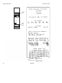
Testing the Printer
Run this test to check the printer. The test prints the settings for several functions,
prints all variations of the character sets, and partially cuts the paper between
each variation. See the “Diagnostics” chapter for a description of the functions.
A sample printout (RS-232C) is shown later in this section. The printouts for other
models models are similar. The test ends with a partial cut, then begins again.
Several feet of paper can be used to print one pass of the test.
Additional diagnostic tests may be performed by a trained service representative.
For more information, see “Diagnostics” later in this book.
1.
Press the On Line Button on the operator panel to take the printer off-line.
The On Line light turns off indicating the printer is off-line.
2.
Press and hold the Paper Feed button while pressing the On Line Button.
3.
Let go of the Paper Feed button once the printing begins.
The printer begins printing the data and character sets. This can be given to a
service representative if it appears there is a problem.
4.
To stop the test, press the On Line button.
The On Line light turns off indicating the printer is off-line.
5.
To return to the on-line mode, press the On Line button again.
The printer is ready to receive and print data from the host system.
May 1996
Setting Up the Printer
7193 Owner’s Guide
On Line
Button
On Line
Paper Out
Paper
Feed
Button
Paper Feed
Operator Panel
3cx39pi
Sample Test Print
24
May 1996
7193 Owner’s Guide
Setting Up the Printer
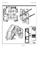
Mounting the Printer on a Wall
Use the wall-mount kit to mount the printer vertically on a wall. See “Ordering
Paper and Supplies” in the chapter, “About the 7193 Printer,” for information on
ordering the printer wall-mount kit.
The kit contains a mounting bracket, screws with plastic anchors, and a label.
Once the printer is mounted on the wall, the operator panel will be upside down.
The label corrects this so the panel can be easily read.
Select a wall that is accessible, but away from main traffic to keep the printer
from being bumped or knocked off. Be sure there are no hidden wires or other
obstructions in the wall where you mount the printer. Keep in mind the length of
the cables when mounting the printer on the wall.
Be sure that the rubber pads have been attached to the bottom of the printer. See
“Attaching the Feet” earlier in this chapter. The rubber pads help the printer to fit
snugly against the mounting bracket.
You will need a 1/4 inch drill bit and either a Phillips or standard screwdriver
(screws are combination Phillips and pan-slotted).
1.
Using the bracket as a template, mark and drill a hole for each plastic anchor
1.25 inches deep.
2.
Insert the anchors into the holes so they are flush with the wall surface and
screw the bracket against the wall, tightening the screws so that the plastic
anchors expand and hold firmly in the wall.
Do not overtighten the screws.
Note: Because the power cable and communication cable connect to the bottom
of the printer, they must be connected before the printer can be attached to the
bracket. If you haven't connected the cables to the printer, do so now. See
“Connecting Communication and Power Cables” earlier in this chapter.
May 1996
3.
Line up the tabs of the bracket with the slots on the back of the printer and
attach the printer to the bracket.
4.
Place the label on the cover.
Setting Up the Printer
158.5mm
6.24 in.
7193 Owner’s Guide
69.8mm
2.75 in.
Screws
79.2mm
3.12 in.
Plastic
Anchors
31.8mm
1.25 in.
30.5mm
1.20 in.
158.5mm
6.24 in.
19.5mm
0.75 in.
19.5mm
0.75 in.
Bracket
Paper Feed
Paper Feed
Paper Out
Paper Out
Slots
On Line
Paper
Release
On Line
Tabs
7193
Printer
Back of
the Center
Bracket
Label
26
May 1996
Operator
Panel
7193 Owner’s Guide
Setting Up the Printer
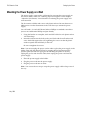
Mounting the Power Supply on a Wall
The power supply comes with a wall-mount kit to mount the power supply on
the wall or under a table. See “Ordering Paper and Supplies” in the chapter,
“About the 7193 Printer,” for information on ordering the power supply and
wall-mount kit.
The kit contains a holder and screws with plastic anchors. Be sure there are no
hidden wires or other obstructions in the wall where you mount the power
supply.
You will need a 1/4 inch drill bit and either a Phillips or standard screwdriver
(screws are combination Phillips and pan-slotted).
1.
Using the bracket as a template, mark and drill a hole for each plastic anchor
1.25 inches deep.
2.
Insert the anchors into the holes so they are flush with the wall surface and
screw the holder against the wall, tightening the screws so that the plastic
anchors expand and hold firmly in the wall.
Do not overtighten the screws.
Note: You must unplug the power cord in order to place the power supply in the
holder. First, take the printer off-line by pressing the On Line button on the
operator panel (the On Line light goes off indicating the printer is off-line),
unplug the power cord from the outlet, then unplug the power cord from the
power supply.
3.
Place the power supply in the holder.
4.
Plug the power cord into the power supply.
5.
Plug the power cord into an outlet.
Note: You can use the tie-wrap to wrap the power supply cable to keep it out of
the way.
May 1996
Setting Up the Printer
7193 Owner’s Guide
44.5mm
1.75 in.
21.8mm
.875 in.
19.1mm
.75 in.
57.2mm
2.25 in.
Plastic
Anchor
Screws
107.9mm
4.25 in.
141.8mm
5.58 in.
26.4mm
1.04 in.
Holder
96.0mm
3.78 in.
Power
Supply
Cable
Power
Supply
Holder
AC Cord
28
May 1996
7193 Owner’s Guide
Solving Problems
Solving Problems
The 7193 printer is a simple, generally trouble-free printer, but from time to time
minor problems may occur. For example, the power supply may be interrupted
or the printhead may overheat for some reason.
Lights on the operator panel will signal that something may not be operating
properly: one green light and one red light may either flash or glow continuously
as described in the following table and on the following pages.
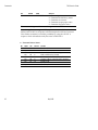
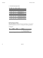
Operator Panel Lights
The following chart describes the operator panel lights. See “Correcting
Problems” on the next page for more information about each of these conditions.
Light
Condition
Green1 On
Meaning
Action Required
Printer is on-line
None
Green1 Off
Printer is unplugged or offline
1
Flashing
Printer is in diagnostics
Green
mode
Off
No fault conditions
Red2
Connect printer to host or
power supply and turn on
Set DIP switch #1 to Off (see
“Setting Switches,” p. 12)
None
Red2
Reload paper, close cover, or
clear paper jam
Wait for printhead to cool down
Red2
On
Paper out, cover open, or
knife won't home
Flashing Printhead too hot or
voltages out of range
1Light labeled On Line.
2Light labeled Paper Out.
May 1996
Solving Problems
7193 Owner’s Guide
Correcting Problems
Operator-Correctable Conditions
The following conditions can be corrected generally without calling for service.
However, if problems persist, contact your service representative. See
“Contacting a Service Representative” on the next page.
Paper Out
Replace the paper roll. Do not operate the printer or host system if the printer
runs out of paper. The printer will not operate without paper, but it may continue
to accept data from the host system. Because the printer cannot print any
transactions, the data may be lost.
See “Loading and Changing Paper” on page 19 for more information. See
“Contacting a Service Representative” on the next page.
Knife Failure or Paper Jam
A problem or jam has occurred with the knife. Open the receipt cover and
visually inspect the knife inside the cover. Clear any jammed paper you can see.
Tear off any excess paper against the tear off blade.
Contact your service representative if this does not resolve the problem. See
“Contacting a Service Representative” on the next page.
Receipt Cover Open
Check that the receipt cover is completely closed. You can tell if it is not closed
properly if it swings open easily. When closed properly, it requires some exertion
to open because of the snug fit.
Service-Related Problems
The following problems may require you to contact your service representative to
correct the problem.
Print Head Over/Under Temperature
There is a problem with the temperature of the printhead. It must remain within
a certain temperature range to operate properly. This problem will most often
occur when the printhead overheats rather than running under temperature.
30
May 1996
7193 Owner’s Guide
Solving Problems
The printhead may overheat when printing in a room where the temperature is
above the recommended operating temperature or when printing graphics
continuously. In either case, the printer will shut off. See “Appendix A:
Specifications” for information on the recommended temperature range for
operating the printer and on the restrictions of continuous graphics printing.
If the operating temperature is too hot, adjust the room temperature or move the
printer to a cooler location. If the printhead is overheating because of printing
graphics continuously, reduce the demand on the printer.
If the printer continues to overheat, contact your service representative. See
“Contacting a Service Representative” on this page.
No Power to Printer or Power Voltages Incorrect
The power being supplied to the printer is not in the normal range. Check that all
connections are correct. Make sure the power supply is plugged in and that the
printer is on-line.
Contact your service representative if this does not resolve the problem. See
“Contacting a Service Representative” on this page.
Print is Light or Spotty
The printhead may be dirty. Clean it with cotton swabs and rubbing alcohol.
Caution: Do not spray the thermal printhead with household cleaner as this may
damage it and the electronics.
Note: The thermal printhead does not normally require cleaning if the
recommended paper grades are used. If non-recommended paper has been used
for an extended period of time, cleaning the printhead with cotton swabs and
rubbing alcohol will not be of much benefit. See “Recommended Suppliers” on
page 4 for the recommended paper grades.
Contact your service representative if the problem is still not resolved. See
“Contacting a Service Representative” on this page.
Contacting a Service Representative
For serious problems, such as the ones mentioned in the previous section, contact
your Axiohm authorized service organization to arrange for a service call.
May 1996
7193 Owner’s Guide
Diagnostics
Diagnostics
The following diagnostic tests are available for the 7193:
•
Level 0 Diagnostics
Performed during the startup cycle
•
Level 1 Diagnostics (setup mode)
Available in a dedicated environment and accessed through the DIP Switches
•
Level 2 Diagnostics
Performed during normal printer operation
Level 0 Diagnostics
The printer performs level 0 diagnostics during the startup cycle when power is
supplied or the printer is brought on-line. Level 0 diagnostics comprise the
following actions:
•
Motors are turned off
•
Microprocessor timing is checked, CRC check of the firmware ROM is
performed, external RAM is read (failure causes level 0 diagnostics to stop;
the printer beeps once when the test is successfully completed)
•
Checks if paper is present
•
Homes knife (failure causes a fault condition)
•
Checks if receipt cover is closed (failure does not interrupt the startup cycle)
When the last step is complete, the Paper Feed button is enabled and the printer
is ready for normal operation. Information about the test is available to the
communication interface through the commands.
If the printer has not been turned on before, or a new EEROM has been installed,
the default values for the printer settings (set in Level 1 Diagnostics) will be
loaded into the EEROM. The printer beeps twice when this occurs. See the tables
in “Level 1 Diagnostics” for the printer settings. If the printer beeps twice at any
other time, it indicates that the EEROM has failed.
May 1996
Diagnostics
7193 Owner’s Guide
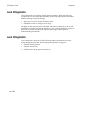
Level 1 Diagnostics
Level 1 Diagnostics (setup mode) allow you to change the settings for various
printer functions (described on the following pages) and to run certain tests
using the DIP switches.
Keep the following information in mind when changing the settings:
•
Turn the power off (not required, but recommended): press the On Line
button (although the printer still receives power, this is sufficient for
changing the DIP switches)
•
The settings can only be changed when the printer is in level 1 diagnostics
(setup mode): switch 1 must be set to On.
•
Turn the power back on. The printer beeps, and the On Line light (green)
blinks.
•
Once the settings have been changed and stored in the EEROM, the DIP
switches must be set back to the on-line settings for the printer to operate.
•
The stored settings for the functions are printed with a dump of all resident
characters during a print test. See “Testing the Printer” on page 23.
•
The default settings are set at the factory and are stored in the history
EEROM.
Caution: If you change the switch settings, be sure they are the correct settings
for that particular function or test to avoid accidentally changing the settings for
another function or test. If the settings are accidentally changed, use the switch
settings shown in the tables throughout this section to change those settings back.
If you need assistance, contact your service representative.
The functions and tests are described in the following order in this section:
34
•
Setting Data Error (RS-232C only) and Data Buffer options
•
Setting printhead resistance
•
Setting default lines per inch
•
Setting partial cut distance
•
Ignoring/using the carriage return
•
Running the data scope mode
May 1996
7193 Owner’s Guide
Diagnostics
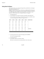
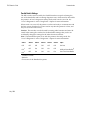
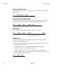
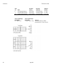
Setting Data Error and Data Buffer options
This function allows you to select the handling of data reception errors (RS-232C
only) and to select the size of the data buffer.
Caution: The DIP switches are set at the factory to predetermined settings and
should generally not be changed. If you must change the settings, do so carefully
to avoid changing other functions. Run the print test to see what the current
selections are for this function. See “Testing The Printer” On Page 23.
1.
Turn the power off.
2.
Turn the printer over and note what the current DIP switch settings are.
3.
Set the switches to the settings in the table you want for data reception errors
and the data buffer.
Switch 1
Switch 2
Switch 3
Switch 4
Switch 5
Switch 6
Option
On
Off
On
Off
Off
Off
“?” for Data Errors1, 2
On
Off
On
Off
Off
On
Ignore Data Errors2
On
Off
On
Off
On
Off
On
Off
On
Off
On
On
4K Byte Data Buffer1,
3
One Line Data Buffer
1Default
2RS-232C only
Choose one of the Data Errors options and one of the Data Buffer options.
4.
Turn the power back on to enter the settings into the EEROM.
The On Line light (green) blinks.
5.
Turn the power off.
6.
Set the DIP switches to the former settings.
DIP switch 1 must be Off to return the printer to the on-line mode.
May 1996
Diagnostics
7193 Owner’s Guide
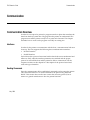
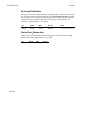
Setting Printhead Resistance
This function allows you to change the setting for the printhead resistance. The
setting (A-H) must match the letter stamped on the heatsink in back of the
printhead. This is visible only by removing the L cover (operator panel) of the
printer. Only a trained service representative may remove this cover.
Caution: The DIP switches are set at the factory to predetermined settings and
should generally not be changed. If you must change the settings, do so carefully
to avoid changing other functions. Run the print test to see what the current
selection is for this function. See “Testing The Printer” On Page 23.
1.
Turn the power off.
2.
Turn the printer over and note what the current DIP switch settings are.
3.
Set the switches to the settings in the table that match the letter stamped on
the heatsink in back of the printhead.
Switch 1
Switch 2
Switch 3
Switch 4
Switch 5
Switch 6
Printhead Setting
On
On
On
Off
Off
Off
A
On
On
On
Off
Off
On
B
On
On
On
Off
On
Off
C
On
On
On
Off
On
On
D
On
On
On
On
Off
Off
E
On
On
On
On
Off
On
F
On
On
On
On
On
Off
G
On
On
On
On
On
On
H
4.
Turn the power back on to enter the settings into the EEROM.
The On Line light (green) blinks.
5.
Turn the power off.
6.
Set the DIP switches to the former settings.
DIP switch 1 must be Off to return the printer to the on-line mode.
36
May 1996
7193 Owner’s Guide
Diagnostics
Setting Default Lines per Inch
This function allows you to set the default for lines per inch to either 7.6 or 6.
Caution: The DIP switches are set at the factory to predetermined settings and
should generally not be changed. If you must change the settings, do so carefully
to avoid changing other functions. Run the print test to see what the current
selection is for this function. See “Testing The Printer” On Page 23.
1.
Turn the power off.
2.
Turn the printer over and note what the current DIP switch settings are.
3.
Set the switches to the settings in the table that match the lines per inch
setting you want as the default setting (when the printer is powered up).
Switch 1
Switch 2
Switch 3
Switch 4
Switch 5
Switch 6
Default LInes per Inch
On
Off
On
On
On
Off
7.6 (Factory Setting)
On
Off
On
On
On
On
6.0
4.
Turn the power back on to enter the settings into the EEROM.
The On Line light (green) blinks.
5.
Turn the power off.
6.
Set the DIP switches to the former settings.
DIP switch 1 must be Off to return the printer to the on-line mode.
May 1996
Diagnostics
7193 Owner’s Guide
Setting Partial Cut Distance
This function allows you to change the length of the partial knife cut: the higher
the number, the longer the cut.
Caution: The DIP switches are set at the factory to predetermined settings and
should generally not be changed. If you must change the settings, do so carefully
to avoid changing other functions. Run the print test to see what the current
selection is for this function. See “Testing The Printer” On Page 23.
1.
Turn the power off.
2.
Turn the printer over and note what the current DIP switch settings are.
3.
Set the switches to the settings in the table that match the cut distance value
you want (the higher the number, the longer the cut ).
Switch 1
Switch 2
Switch 3
Switch 4
Switch 5
Switch 6
Cut Distance Value
On
On
Off
Off
Off
Off
0
On
On
Off
Off
Off
On
1
On
On
Off
Off
On
Off
2
On
On
Off
Off
On
On
3
On
On
Off
On
Off
Off
4
On
On
Off
On
Off
On
5 (Default)
On
On
Off
On
On
Off
6
On
On
Off
On
On
On
7
4.
Turn the power back on to enter the settings into the EEROM.
The On Line light (green) blinks.
5.
Turn the power off.
6.
Set the DIP switches to the former settings.
DIP switch 1 must be Off to return the printer to the on-line mode.
38
May 1996
7193 Owner’s Guide
Diagnostics
Ignoring/Using the Carriage Return
This function allows the printer to ignore or use the Carriage Return (Hex 0D)
command depending on the application. Some applications expect the command
to be ignored while others use the command as a print command.
Caution: The DIP switches are set at the factory to predetermined settings and
should generally not be changed. If you must change the settings, do so carefully
to avoid changing other functions.
1.
Turn the power off.
2.
Turn the printer over and note what the current DIP switch settings are.
3.
Set the switches to the settings in the table that match you want for ignoring
or using the Carriage Return command.
Switch 1
Switch 2
Switch 3
Switch 4
Switch 5
Switch 6
Option
On
Off
On
On
Off
On
Ignore CR (Hex 0D)
On
Off
On
On
Off
Off
Use CR (Hex 0D) as
Print Command
(Default)*
*Emulates the NCR 7150™ printer.
4.
Turn the power back on to enter the settings into the EEROM.
The On Line light (green) blinks.
5.
Turn the power off.
6.
Set the DIP switches to the former settings.
DIP switch 1 must be Off to return the printer to the on-line mode.
May 1996
Diagnostics
7193 Owner’s Guide
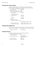
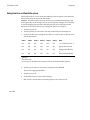
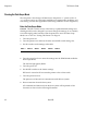
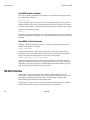
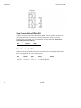
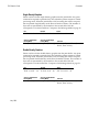
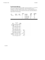
Running the Data Scope Mode
This test prints a Hex dump of all data sent to the printer: “1” prints as Hex 31,
“A” as Hex 41 and so on. This helps troubleshoot communication problems, and
runs during a normal host application (after being enabled in level 1 diagnostics).
Enter the Data Scope Mode
Caution: The DIP switches are set at the factory to predetermined settings and
should generally not be changed. If you must change the settings, do so carefully
to avoid changing other functions. Run the print test to see if the Data Scope
Mode is on or off. See “Testing The Printer” On Page 23.
1.
Turn the power off.
2.
Turn the printer over and note what the current DIP switch settings are.
3.
Set the switches to the settings in the table.
Switch 1
Switch 2
Switch 3
Switch 4
Switch 5
Switch 6
On
Off
Off
On
Off
On
4.
Turn the power back on to enter the settings into the EEROM and enable the
Data Scope Mode.
The On Line light (green) blinks.
5.
Turn the power off.
6.
Set the DIP switches to the former settings.
DIP switch 1 must be Off to return the printer to the on-line mode.
7.
Turn the power back on.
The printer is on-line and can communicate with the host system.
8.
Run a transaction from the host system.
All commands and data sent from the host system will be printed as Hex
characters as shown in the following illustration.
40
May 1996
7193 Owner’s Guide
Diagnostics
1BH
61H
30H
6DH
1BH
00H
20H
61H
21H
1BH
37H
6CH
20H
64H
31H
2FH
54H
06H
35H
49H
54H
1BH
36H
6DH
77H
6DH
20H
70H
6FH
16 H0CH
54H 68H
61H 63H
20H 48H
1BH
65H
74H
65H
21H
72H
0AH
61H
Datascope Mode Print Test
Exit the Data Scope Mode
1.
Turn the power off.
2.
Set the switches to the settings in the table.
Switch 1
Switch 2
Switch 3
Switch 4
Switch 5
Switch 6
On
Off
Off
On
Off
Off
3.
Turn the power back on to enter the settings into the EEROM and disable the
Data Scope Mode.
The On Line light (green) blinks.
4.
Turn the power off.
5.
Set the DIP switches to the former settings.
DIP switch 1 must be Off to return the printer to the on-line mode.
6.
Turn the power back on.
The printer is on-line and can communicate normally with the host system.
May 1996
Diagnostics
7193 Owner’s Guide
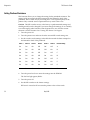
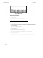
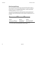
Testing Receipt Printing
This function allows you to select various print tests. You can also test the
printing by following the procedures in “Testing the Printer” on page 23 without
having to change the DIP switches. A sample test printout is on page 24.
Caution: The DIP switches are set at the factory to predetermined settings and
should generally not be changed. If you must change the settings, do so carefully
to avoid changing other functions.
1.
Turn the power off.
2.
Turn the printer over and note what the current DIP switch settings are.
3.
Set the switches to the settings in the table that match the test you want.
Switch 1
Switch 2
Switch 3
Switch 4
Switch 5
Switch 6
Option
On
Off
Off
Off
Off
Off
Sample Receipt1
On
Off
Off
Off
Off
On
On
Off
Off
Off
On
Off
Continuous Sample
Receipt
Character Sets1
On
Off
Off
Off
On
On
Continuous Character
Sets2
1The Paper Feed button is used to begin the test.
2Default
4.
Turn the power back on to enter the settings into the EEROM.
The On Line light (green) blinks. If either the continuous sample receipt or the
continuous character sets is selected, the printer will automatically begin
printing.
5.
Press the Paper Feed button to print the sample receipt or the character sets
(whichever was selected).
6.
Press the Paper Feed button or turn the printer off to stop the test.
7.
Turn the power off.
8.
Set the DIP switches to the former settings.
DIP switch 1 must be Off to return the printer to the on-line mode.
42
May 1996
7193 Owner’s Guide
Diagnostics
Level 2 Diagnostics
Level 2 diagnostics run during normal printer operation. When the following
conditions occur, the printer automatically turns off the appropriate motors and
disables printing to prevent damage:
•
Paper out, cover off, or knife unable to home
•
Printhead too hot or voltages out of range
The lights on the operator panel will signal when these conditions occur as well
as indicate what state or mode the printer is in. See “Solving Problems” earlier in
this book for a table describing the operator panel lights and for general
troubleshooting information.
Level 3 Diagnostics
Level 3 diagnostics keep track of the following tallies and prints them on the
receipt during the print test. See the sample test printout on page 24.
May 1996
•
Number of lines printed
•
Number of knife cuts
•
Number of hours the printer has been on
7193 Owner’s Guide
Communication
Communication
Communication Overview
In order for a receipt to be printed, a program must be in place that translates the
data from the host system into a language that the printer can understand. This
program must tell the printer exactly how to print each character. This chapter
describes how to create such a program or modify an existing one.
Interfaces
In order for the printer to communicate with the host, a communication link must
be set up. The 7193 supports the following three communication interfaces:
•
RS-232C Interface
•
Parallel Interface
Each of these has a protocol associated with it that the host must understand and
adhere to. Only when the interface parameters are matched and the proper
protocol is used will the host and the printer be able to communicate. See the
respective sections in this chapter for a description of the protocol associated
with each type of interface.
Sending Commands
Once the communication link is established, commands can be sent to the printer.
This section describes how to send commands to the printer using DOS and
BASIC. This section does not take into account the necessary protocol, but is
meant as a general introduction to how the printer functions.
May 1996
Communication
7193 Owner’s Guide
Using DOS to Send Commands
One way of getting commands to the printer is to send them directly from DOS.
For example, the command
COPY CON: COM1:
sets the computer up such that the Hex code corresponding to any key that was
pressed would be sent to the communication port COM1 when the COPY mode
is exited. If the printer is connected to COM1, then the data will go to the printer.
Exit the COPY mode by typing
CTRL Z
and then pressing the ENTER key. Once the computer knows to direct data from
any print command to the proper port, commands can be sent from any software
program.
Using BASIC to Send Commands
In BASIC, printer commands are sent as a string of characters preceded by the
LPRINT command. For example,
LPRINT CHR$(&H0A)
sends the hexadecimal number 0A to the printer, which causes the printer to
print the contents of its print buffer. Previously sent commands tell the printer
exactly how this data should appear on the paper. For example,
LPRINT CHR$(&H12); "ABC"; CHR$(&H0A)
sends the Hex numbers 12 41 42 43 0A to the printer. This causes the printer to
set itself to double wide mode (12), load the print buffer with “ABC” (41 42 43),
and finally, print (0A). Again, the communication link that the BASIC program
outputs to must be matched to that of the printer.
RS-232C Interface
The RS-232C interface uses either XON/XOFF or DTR/DSR protocol. For
XON/XOFF, a particular character is sent back and forth between the host and
the printer to regulate the communication. For DTR/DSR, changes in the
DTR/DSR signal coordinate the information flow.
The RS-232C version of the 7193 offers the standard options which are selected
with the DIP switches. The switch settings are shown on page 50.
46
May 1996
7193 Owner’s Guide
Communication
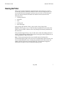
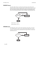
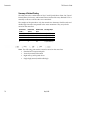
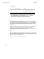
XON/XOFF Protocol
The XON/XOFF characters coordinate the information transfer between the
printer and the host system. The printer sends an XON character when it is ready
to receive data and it sends an XOFF character when it cannot accept any more
data. The software on the host system must monitor the communication link as
shown in the following flowchart in order to send data at the appropriate times.
Was an XON
or XOFF charactor
last received?
13 HEX
XOFF
Wait for
XON character
XON
11 HEX
Send Data
XON character = Hex 11.
XOFF character = Hex 13.
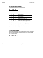
DTR/DSR Protocol
The DTR signal is used to control data transmission to the printer. It is driven
low when the printer is ready to recieve data and driven high when it cannot
accept any more data. Data is transmitted from the printer after it confirms that
the DSR signal is low.
Is DTR
High or Low
Low
Send Data
May 1996
High
Wait for
DTR to Go Low
Communication
7193 Owner’s Guide
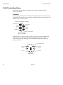
RS-232C Technical Specifications
This section describes the pin settings for the connectors and the RS-232C
interface parameters.
Connectors
The following illustration shows the RS-232C communication connector and pin
assignments. The connector is a 9-pin male D-shell connector and is located in the
hollow cavity under the printer.
Function Pin Numbers Function
Logic Ground 5
9 Not Used
DTR 4
8 CTS
TXD 3
7 RTS
RXD 2
6 DSR
Not Used 1
Shell - Frame Ground
Printer View (Male)
With RS-232C, the 7193 is always remotely powered. The following illustration
shows the power cable connector and pin assignments. The power cable
connector is 6-pin mini DIN plug and is located in the small cavity under the
printer at the front.
Shell Frame Ground
Return 5
6 +24 Volts
Return 3
4 +24 Volts
Return 1
2 +24 Volts
Pin View End
48
May 1996
7193 Owner’s Guide
Communication
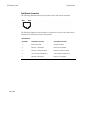
Cash Drawer Connectors
The following illustration shows the pinouts for the cash drawer connector.
Pin 1
Pin 6
The following table shows the pinouts for cash drawers 1 and 2. The cash drawer
connectors are located at the rear of the printer.
RS-232C Printers
May 1996
Pin Number
Cash Drawer 1 Connector
Cash Drawer 2 Connector
1
Frame Ground
Frame Ground
2
Drawer 1 Solenoid
Drawer 2 Solenoid
3
Drawer 1 Status Switch
Drawer 2 Status Switch
4
+24 Volts (to Solenoid +)
+24 Volts (to Solenoid +)
5
Drawer 2 Solenoid
Drawer 1 Solenoid
6
Ground (Status Switch Return)
Ground (Status Switch Return)
Communication
7193 Owner’s Guide
Switch Settings
The DIP switches are located on the printed circuit board and are accessed from
the bottom of the printer. You do not need to remove any covers to change the
DIP switches.
The DIP switches are used to set the RS-232C parameters and the Data Error and
Data Buffer options as shown. These parameters must match those of the host
system in order for the host system and the printer to communicate. See “Level 1
Diagnostics” in the “Diagnostics” chapter for more information.
Caution: The switches can also be used for setting other functions and tests. Be
careful when setting the switches for the RS-232C settings that you do not
accidentally change the settings for the other functions and tests.
Use a paper clip or other pointed object to set the switches.
1.
Press the On Line button to take the printer off-line.
2.
Turn the printer over and set the switches to the desired settings shown in
the table on the next page.
Switch 1 must be set to Off when setting switches for the RS-232C settings.
This puts the printer in the on-line mode to communicate with the host
system.
Caution: Do not set DIP switch 1 to On. Setting switch 1 to On puts the printer in
level 1 diagnostics (setup) mode where other functions and tests can be changed.
50
May 1996
7193 Owner’s Guide
Communication
DIP Switch Settings for RS-232C Parameters
Switch
Settings
Description
1
OFF
ON
OFF
ON
OFF
ON
OFF
ON
5
OFF
ON
OFF
ON
RS-232C Communication: On-line Mode (Default)
Level 1 Diagnostics: Setup Mode
DTR/DSR Protocol (Default)
XON/XOFF Protocol
Parity Disabled (Default)
Parity Enabled
Odd Parity
Even Parity
2
3
4
5, 6
6
OFF
OFF
ON
ON
19,200 Baud
9600 Baud (Default)
4800 Baud
1200 Baud
Note: The following options are set with the printer in the setup mode. See
“Level 1 Diagnostics” in the “Diagnostics” chapter for more information.
DIP Switch Settings for Data Error and Data Buffer Options (Choose one from each option)
Switch 1
Switch 2
Switch 3
Switch 4
Switch 5
Switch 6
Option
On
Off
On
Off
Off
Off
“?” for Data Errors*
On
Off
On
Off
Off
On
Ignore Data Errors
On
Off
On
Off
On
Off
4K Byte Data Buffer*
On
Off
On
Off
On
On
One Line Data Buffer
*Default
May 1996
Communication
7193 Owner’s Guide
Parallel Interface
Parallel Protocol
The 7193 uses a standard PC-compatible parallel interface. The following
illustration shows the timing diagram for the interface protocol.
52
1.
ACK/ will not go high until STROBE/ goes high.
2.
When the printer is not ready to receive more data, ACK/ will be sent, but
BUSY will remain high.
3.
When the power is turned on or the printer is reset, an ACK/ will be sent
during initialization.
4.
Typical time from STROBE/ to ACK/ is approximately 44 µ seconds.
May 1996
7193 Owner’s Guide
Communication
Parallel Technical Specifications
Parallel Connectors
1 Strobe /
2 D0
Pulled up to +5V 14
3 D1
Fault / 15
4 D2
Reset in / 16
5 D3
Pulled up to +5V
6 D4
Ground 18
7 D5
Ground 19
8 D6
Ground 20
9 D7
Ground 21
11 Busy
12 Paper Exhaust
10 ACK /
Ground 22
Function
Ground 23
Pin Numbers
Ground 24
Pin Numbers
Ground 25
Function
13 SELECT OUT
The following illustration shows the Parallel communication connector and pin
assignments. The connector is at the rear of the printer.
The connector for the power supply cable has the following pin assignments. The
power cable connector is in the small cavity under the printer at the front.
Shell Frame Ground
Return 5
6 +24 Volts
Return 3
4 +24 Volts
Return 1
2 +24 Volts
Pin View End
May 1996
Communication
7193 Owner’s Guide
Cash Drawer Connectors
The following illustration shows the pinouts for the cash drawer connector.
Pin 1
Pin 6
The following table shows the pinouts for cash drawers 1 and 2. The cash drawer
connectors are located at the rear of the printer.
Parallel Printers
Pin Number
Cash Drawer 1 Connector
Cash Drawer 2 Connector
1
Frame Ground
Frame Ground
2
Drawer 1 Solenoid
3
Drawer 1 Status Switch
Drawer 2 Solenoid (Optional
by jumper: JPR4)
Drawer 2 Status Switch
4
+24 Volts (to Solenoid +)
+24 Volts (to Solenoid +)
5
Drawer 2 Solenoid (Optional by Drawer 2 Solenoid
jumper: JPR3)
Ground (Status Switch Return) Ground (Status Switch Return)
6
54
May 1996
7193 Owner’s Guide
Communication
Parallel Switch Settings
The DIP switches are not used by the Parallel interface except for selecting the
size of the data buffer and for running diagnostic tests, which must be done while
the printer is in level 1 diagnostics (setup mode) with switch 1 set to On. See
“Level 1 Diagnostics” in the “Diagnostics” chapter for more information.
When switch 1 is set to Off, the printer is on-line and ready to communicate with
the host system. Switches 2-6 are not used at any time the printer is on-line, and
they are set to Off at the factory.
Caution: The switches can also be used for setting other functions and tests. Be
careful when setting the switches for the Data Buffer settings that you do not
accidentally change the settings for the other functions and tests.
Note: The Data Buffer option is set with the printer in the setup mode. See
“Level 1 Diagnostics” in the “Diagnostics” chapter for more information.
Switch 1
Switch 2
Switch 3
Switch 4
Switch 5
Switch 6
Option
Off
Off
Off
Off
Off
Off
On-line
On1
Off
On
Off
On
Off
4K Byte Data Buffer2
On1
Off
On
Off
On
On
One Line Data Buffer
1Printer is off-line
2Default
Choose one of the Data Buffer options.
May 1996
7193 Owner’s Guide
Commands
Commands
The commands control all operations and functions of the 7193 printer, from
selecting the size and placement of characters and graphics on the receipt to
feeding and cutting the paper.
Note: All versions of the 7193 use the same commands as listed in this section
unless otherwise noted. For example, the Parallel interface does require unique
commands for controlling the cash drawer.
The 7193 commands emulate two printers: the NCR 7150™ Multifunction printer
and the Epson TM-T80™ Thermal printer. Any of the commands from either set
may be used in any combination to program a host system to communicate with
the 7193 (unless otherwise noted).
Some commands listed and described here are not implemented in the 7193 (they
are identified as not implemented). If received, they are ignored and not sent to
the print buffer as data. Non-legal commands are sent to the print buffer as data.
Command List
This section groups the commands according to the following categories:
•
Printer Function Commands
•
Print Characteristics Commands
•
Graphics Commands
•
Printer Status Commands
•
Real Time Commands
•
Bar Code Commands
Within each group, the commands are listed in numerical order of their Hex
codes. The page number refers to where a complete description of each command
is given in the “Command Descriptions” section which begins on page 63.
May 1996
Commands
7193 Owner’s Guide
Printer Function Commands
These commands control the following basic printer functions and are listed in
numerical order of their Hex codes:
•
Printing
•
Feeding the paper
•
Resetting the printer
•
Cutting the paper
•
Opening the cash drawers
Printer Function Commands
58
Hex Code
Command
Page
09
Horizontal Tab
63
0A
Line Feed
63
0D
Carriage Return
64
10
Clear Printer
64
14 n
Feed n Print Lines
64
15 n
Feed n Dot Rows
65
16 n
Add n Extra Dot Rows
65
17
Print
65
19
1B 69
1A
1B 6D
1B 07
Full Knife Cut
66
Partial Knife Cut
66
Generate Tone
66
1B 14 n
Set Column
66
1B 20 n
Set Character Right Side Spacing (Not Implemented)
67
1B 24 etc.
Set Absolute Starting Position
67
1B 32
Set Line Spacing to 1/6 Inch
68
1B 33 n
Set Line Spacing to n Minimum Units
68
May 1996
7193 Owner’s Guide
Commands
Printer Function Commands
May 1996
Hex Code
Command
Page
1B 3D n
Select Printer
68
1B 40
Initialize Printer
68
1B 44 etc.
Set Horizontal Tab Positions
69
1B 4A n
Print and Feed n Minimum Units
69
1B 5C etc.
Set Relative Starting Position
70
1B 61 n
Align Character Positions
71
1B 63 34 n
Select Sensors to Stop Printing (Not Implemented)
71
1B 63 35 n
Enable or Disable Panel Switch
71
1B 64 n
Print and Feed n Lines
71
1B 6A k
Read from Non-Volatile Memory
72
1B 70 n etc.
Generate Pulse to Open Cash Drawer
72
1B 73 n etc.
Write to Non-Volatile Memory
72
Commands
7193 Owner’s Guide
Print Characteristics Commands
These commands control what the printed information looks like and are listed in
numerical order of their Hex codes.
Print Characteristics Commands
60
Hex Code
Command
Page
12
Select Double-Wide Characters
73
13
Select Single-Wide Characters
73
1B 12
Rotate Characters Counter-Clockwise
73
1B 16 n
Select Pitch (Column Width)
74
1B 21 m
Set Print Mode
74
1B 25 n
Select Character Set
75
1B 26 etc.
Define User-Defined Character Set
75
1B 3A 0 0 0
Copy Character Set From ROM to RAM
76
1B 52 n
1B 74 n
1B 56 n
Select Character Code Table
76
Set or Cancel Rotated Characters Clockwise
77
1B 7B n
Set or Cancel Upside-Down Characters
77
May 1996
7193 Owner’s Guide
Commands
Graphics Commands
These commands print graphics data and are listed in numerical order of their
Hex codes.
Graphics Commands
Hex Code
Command
Page
1B 24 etc.
Set Absolute Starting Position1
79
1B 2A m etc.
Set Bit Image Mode
79
1B 4B etc.
Single-Density Graphics
81
1B 4C etc.
1B 59 etc.
1D 2A etc.
Double-Density Graphics
81
Define Downloaded Bit Image
82
1D 2F m
Print Downloaded Bit Image
83
1This printer function command is also used in graphics to emulate an Epson
LQ-950™ printer to handle graphics output from word processing programs.
Printer Status Commands
These commands send printer status information to the host system and are
listed in numerical order of their Hex codes.
Printer Status Commands
May 1996
Hex Code
Command
Page
1B 75 0
Transmit Cash Drawer Status (RS-232C Only)
84
1B 75 n
Request Alternate Status (Parallel Only)
85
1B 76
Transmit Printer Status (Not Implemented for 86
Parallel)
Commands
7193 Owner’s Guide
Real Time Commands
These commands correct difficulties with the original version of the 7193 RS-232C
communication interface.
Real Time Commands
Hex Code
Command
Page
1D 04 n
Real Time Status Transmission, GS Sequence
91
10 04 n
Real Time Status Transmission, DLE Sequence
92
1D 03 n
Real Time Request to Printer, GS Sequence
94
10 05 n
Real Time Request to Printer, DLE Sequence
95
1D 05
Real Time Printer Status Transmission
96
Bar Code Commands
These commands print bar codes. HRI means Human Readable Interface and are
listed in numerical order of their Hex codes.
Bar Code Commands
62
Hex Code
Command
Page
1D 48 n
Select Printing Position of HRI Characters
98
1D 66 n
Select Pitch for HRI Characters (Not Implemented)
98
1D 68 n
Select Height of Bar Code
98
1D 6B n etc.
Print Bar Code
99
1D 6B 49 n
Print Code 128 Bar Code
100
1D 77 n
Select Width of Bar Code
100
May 1996
7193 Owner’s Guide
Commands
Command Descriptions
This section lists the commands with their Hex, Decimal, and ASCII codes. The
commands are grouped in the following categories:
•
Printer Function Commands
•
Print Characteristics Commands
•
Graphics Commands
•
Printer Status Commands
•
Real Time Commands
•
Bar Code Commands
Printer Function Commands
The printer function commands control the following basic printer functions and
are described in order of their Hex codes:
•
Printing and feeding paper
•
Cutting paper
•
Resetting printer
•
Performing miscellaneous functions
Horizontal Tab
Moves the print position to the next tab position set by the Set Horizontal Tab
Positions (1B 44 n1 ... n32 00) command. The print position is set to column one
after each line.
Hex
Decimal
ASCII
09
9
HT
Line Feed
Prints one line from the buffer and feeds paper one line.
May 1996
Hex
Decimal
ASCII
0A
10
LF
Commands
7193 Owner’s Guide
Carriage Return
Prints one line from the buffer and feeds paper one line. The printer can be set
through the DIP switches to ignore or use this command. Some applications
expect the command to be ignored while others use it as print command. See
“Ignoring/Using the Carriage Return” in the “Diagnostics” chapter for more
information.
Hex
Decimal
ASCII
0D
13
CR
Clear Printer
Clears the print line buffer without printing and sets the printer to the following
condition:
•
Double-Wide (12) command is cancelled
•
Line Spacing, Pitch, and User-Defined Character Sets are maintained at
current selections (RAM is not affected)
•
Single-Wide, Single-High, Non-Rotated, and Left-Aligned characters are set
•
Printer is restarted and error status is cleared in a fault condition
•
Returns paper exhaust to the paper status line if an alternate status has been
requested (Parallel interface only)
Hex
Decimal
ASCII
10
16
DLE
Feed n Print Lines
Feeds the paper n lines at the current line height without printing.
64
Hex
Decimal
ASCII
Value of n
14 n
20 n
DC4 n
0-255
May 1996
7193 Owner’s Guide
Commands
Feed n Dot Rows
Feeds the paper n dot rows (n/152 inch, n/6 mm), without printing.
Hex
Decimal
ASCII
Value of n
Receipt
Slip
15 n
21 n
NAK n
0-255
n/152 inch
n/72 inch
Add n Extra Dot Rows
Adds n extra dot rows (n/152 inch, n/6 mm) to the character height to increase
space between print lines or decrease the number of lines per inch.
Hex
Decimal
ASCII
Value of n
Default
16 n
22 n
SYN n
0-12
2
The following table shows the relationship between the number of lines per inch
and each extra dot row added:
Extra
Rows
Lines Per
Inch
Dot
Rows
Extra
Rows
Lines Per
Inch
Dot
Rows
0
8.5
18
7
6.1
25
1
8.0
19
8
5.9
26
2
7.6
20
9
5.6
27
3
7.2
21
10
5.4
28
4
7.0
22
11
5.2
29
5
6.6
23
12
5.1
30
6
6.3
24
Print
Prints one line from the buffer and feeds paper one line.
May 1996
Hex
Decimal
ASCII
17
23
ETB
Commands
7193 Owner’s Guide
Full Knife Cut
This command is implemented the same as Partial Knife Cut (1A/1B 6D).
Hex
Decimal
ASCII
19
1B 69
25
27 105
EM
ESC i
Partial Knife Cut
Partially cuts the receipt, leaving .20 inch (5 mm) of paper. The length of the cut
can be changed through the DIP switches. See “Setting Partial Cut Distance” in
the “Diagnostics” chapter. The cut edge is 108 dot rows or .71 inch (18 mm)
above the print station. It is valid only at the beginning of a line.
Hex
Decimal
ASCII
1A
1B 6D
26
27 109
SUB
ESC m
Generate Tone
Generates an audible tone.
Hex
Decimal
ASCII
1B 07
27 7
ESC BEL
Set Column
Prints the first character of the next print line in column n. It must be sent for
each line not printed at column one. The value of n is set to one after each line. It
cannot be used with Single- or Double-Density graphics.
66
Hex
Decimal
ASCII
Value of n
1B 14 n
27 20 n
ESC DC4 n
1-44 (Standard Pitch)
1-56 (Compressed pitch)
May 1996
7193 Owner’s Guide
Commands
Set Character Right-Side Spacing
This command is not implemented and is ignored if received.
Hex
Decimal
ASCII
1B 20 n
27 32 n
ESC (SPACE) n
Set Absolute Starting Position
Sets the print starting position to the specified number of dots (up to the right
margin) from the beginning of the line. The print starting position is reset to the
first column after each line.
Hex
Decimal
ASCII
1B 24 n1 n2
27 36 n1 n2
ESC $ n1 n2
n = Number of dots to be moved from the
beginning of the line
n1 = Remainder after dividing n by 256
n2 = Integer after dividing n by 256
The values for n1 and n2 are two bytes in low byte, high byte word orientation.
Determine the value of n by multiplying the column for the absolute starting
position by 10 (standard pitch) or 8 (compressed pitch). The example shows how
to calculate column 29 (10 dots per column) as the absolute starting position.
28 x 10 = 280 dots (beginning of column 29)
280/256 = 1, remainder of 24
n1 = 24
n2 = 1
Note: This command is also used in the graphics mode to emulate the Epson LQ950™ dot matrix printer. See “Graphics Commands” later in this chapter for
more information.
May 1996
Commands
7193 Owner’s Guide
Set Line Spacing to 1/6 Inch
Sets the line spacing to 1/6 of an inch (4.25 mm). It is not affected by the Print
(17) command.
Hex
Decimal
ASCII
Default
1B 32
27 50
ESC 2
0.13 Inch (3.33 mm)
Set Line Spacing to n Minimum Units
Sets the line spacing to n/360 of an inch. The minimum line spacing is 8.5 lines
per inch. The line spacing equals the character height when n is too small.
Hex
Decimal
ASCII
Value of n
Default
1B 33 n
27 51 n
ESC 3 n
0-255
0.13 Inch (3.33 mm)
Select Printer
This command is not implemented and is ignored if received.
Hex
Decimal
ASCII
Value of n
Default
1B 3D n
27 61 n
ESC = n
0 (bit 0), printer not selected
1 (bit 0), printer selected
1
Initialize Printer
Clears the print line buffer and resets the printer to the following default
selections (startup configuration):
68
•
Single-Wide, Single-High, Non-Rotated, and Left-Aligned characters are set
•
Extra Dot Rows are set to two
•
User-defined characters or logo graphics (from RAM) are cleared
•
Character Set is set to Code Page 437 (default)
•
Character Pitch is reset to 15.2 CPI and column width to 44 (default)
•
Returns paper exhaust to the paper status line if an alternate status has been
requested (Parallel interface only)
Hex
Decimal
ASCII
1B 40
27 64
ESC @
May 1996
7193 Owner’s Guide
Commands
Set Horizontal Tab Positions
Sets up to 32 horizontal tab positions in ascending order n columns from column
one, but does not move the print position. See the Horizontal Tab (09) command.
The command ends with Hex 00; Hex 1B 44 00 clears all tabs. The tabs cannot be
set higher than the column width of the current pitch: standard pitch = 44
columns; compressed pitch = 56 columns.
Hex
Decimal
1B 44 n1 ... 27 68 n1 ...
n32 00
n32 00
ASCII
Value of n
Default
ESC D n1 ...
n32 00
Column for Tab
Minus 1
Every 8 chars. from
col. 1 (9, 17, 25, etc.)
Print and Feed n Minimum Units
Prints one line from the buffer and feeds the paper n/360 inch. The line height
equals the character height when n is too small.
May 1996
Hex
Decimal
ASCII
Value of n
1B 4A n
27 74 n
ESC J n
0-255
Commands
7193 Owner’s Guide
Set Relative Starting Position
Moves the print starting position the specified number of dots either right (up to
the right margin) or left (up to the left margin) of the current position.
The print starting position is reset to the first column after each line.
Hex
Decimal
ASCII
Value of n
1B 5C n1 n2
27 92 n1 n2
ESC \ n1 n2
See Examples Below
To Move the Relative Starting Position Right of the Current Position
n = Number of dots to be moved right of the current position
n1 = Remainder after dividing n by 256
n2 = Integer after dividing n by 256
The values for n1 and n2 are two bytes in low byte, high byte word orientation.
Determine the value of n by multiplying the number of columns to move right of
the current position by 10 (standard pitch) or 8 (compressed pitch). The example
shows how to set the relative position two columns in standard pitch (10 dots per
column) to the right of the current position.
2 x 10 = 20 dots (two columns to be moved right of the current position)
20/256 = 0, remainder of 20
n1 = 20
n2 = 0
To Move the Relative Starting Position Left of the Current Position
n = Number of dots to be moved left of the current position
n1 = Remainder after dividing (65,536-n) by 256
n2 = Integer after dividing (65,536-n) by 256
The values for n1 and n2 are two bytes in low byte, high byte word orientation.
Determine the value of n by multiplying the number of columns to move left of
the current position by 10 (standard pitch) or 8 (compressed pitch). The example
shows how to set the relative position two columns in standard pitch (10 dots per
column) to the left of the current position.
2 x 10 = 20 dots (two columns to be moved left of the current position)
65,536-20 = 65516
65,516/256 = 255, remainder of 236
n1 = 236
n2 = 255
70
May 1996
7193 Owner’s Guide
Commands
Align Character Positions
Specifies the alignment of characters, graphics, logos, and bar codes (see table). It
is valid only at the beginning of a line.
Hex
Decimal
ASCII
Value of n
Default
1B 61 n
27 97 n
ESC a n
0 (Left Aligned)
1 (Center Aligned)
2 (Right Aligned)
0
Select Sensors to Stop Printing
This command is not implemented and is ignored if received.
Hex
Decimal
ASCII
1B 63 34 n
27 99 52 n
ESC c 4 n
Enable or Disable Panel Switch
Toggles the panel switches on and off. Functions that require the panel switches
cannot be used when the panel switches are disabled with this command.
Hex
Decimal
ASCII
Value of n
Default
1B 63 35 n
27 99 53 n
ESC c 5 n
0 = Enable
1 = Disable
0
Print and Feed n Lines
Prints one line from the buffer and feeds paper n lines at the current line height.
May 1996
Hex
Decimal
ASCII
Value of n
1B 64 n
27 100 n
ESC d n
1-255 (0 interpreted as 1)
Commands
7193 Owner’s Guide
Read from Non-Volatile Memory
Reads a two-byte word from location k in history EEROM. The printer will return
the word at the next available opportunity.
This command is not available on Parallel printers.
Hex
Decimal
ASCII
Value of k
1B 6A k
27 106 k
ESC j k
0-63 (Hex)
Generate Pulse to Open Cash Drawer
Outputs a pulse to open the cash drawer.
The value for either p1 or p2 is the Hex number multiplied by 2 msec. to equal the
total time. The off-time is the delay before the printer performs the next
operation.
Hex
Decimal
ASCII
Value of n
Value of p
1B 70
n p1 p2
27 112
n p1 p2
ESC p
n p1 p2
00 = Drawer 1
01 = Drawer 2
p1 (Hex) x 2 msec. = On-time
p2 (Hex) x 2 msec. = Off-time
Write to Non-Volatile Memory
Writes two-byte word n1:n2 to location k in history EEROM.
72
Hex
Decimal
ASCII
Value of n
Value of k
1B 73
n1 n2 k
27 115
n1 n2 k
ESC s
n1 n2 k
n1 = 1st Byte
n2 = 2nd Byte
16-63 (Hex Locations 00-15 are
Reserved)
May 1996
7193 Owner’s Guide
Commands
Print Characteristics Commands
These commands control what the printed information looks like: selection of
character sets, definition of custom-defined characters, and setting of margins.
The commands are described in order of their Hex codes
Select Double-Wide Characters
Prints double-wide characters. The printer is reset to single-wide mode after a
line has been printed or a Clear Printer (10) command is received. It may be used
with single-wide characters on the same line, but not with Single and Double
Density Graphics modes.
Hex
Decimal
ASCII
12
18
DC2
Select Single-Wide Characters
Prints single-wide characters. It may be used with double-wide characters on the
same line, but not with Single and Double Density Graphics modes.
Hex
Decimal
ASCII
13
19
DC3
Rotate Characters Counter-Clockwise
Rotates characters 90 degrees counter-clockwise. It remains in effect until the
printer is reset or until a Clear Printer (10), Set/Cancel Upside-Down Print (1B
7B), or Set/Cancel Rotated Print (1B 56) command is received. It is valid only at
the beginning of a line. It cannot be used with non-rotated print on the same line.
See “Summary of Rotated Printing” on page 78.
May 1996
Hex
Decimal
ASCII
1B 12
27 18
ESC DC2
Commands
7193 Owner’s Guide
Select Pitch (Column Width)
Selects the character pitch for a print line. It is valid only at the beginning of a
line. Standard and compressed pitches cannot be used together on the same line.
See “Appendix B” for a description of both pitches.
Hex
Decimal
ASCII
Value of n
Default
1B 16 n
27 22 n
ESC SYN n
0 = Standard Pitch
1 = Compressed Pitch
0
Set Print Mode
Selects the print mode: standard, compressed, double high, or double wide. See
“Appendix B” for a description of standard and compressed character pitches.
Hex
Decimal
ASCII
Value of m
Default
1B 21 m
27 33 m
ESC ! m
See Next Table
0
Value of m
Bit
Function
0
1
Bit 01
Pitch
Compressed Pitch
56 Col/Line, 19 CPI (Rec)
80 Col/Line, 17.1 CPI (Slip)
Bit 4
Double
High3
Standard Pitch2
44 Col/Line, 15 CPI (Rec)
66 Col/Line, 13.9 CPI (Slip)
Canceled
Bit 5
Double
Wide
Canceled
Set
Set
1Bit 0 is ignored unless it is at begining of line. Bits 1, 2, 3, 6, 7 are not used.
2Standard and compressed pitch cannot be used together in the same line.
3Cannot be used together with normal height in same line.
74
May 1996
7193 Owner’s Guide
Commands
Select Character Set
Selects the character set. The character sets cannot be used together on the same
line. When an undefined RAM character is selected, the Code Page 437 character
is used. See “Appendix B” for the character sets.
Hex
Decimal
ASCII
Value of n
Default
1B 25 n
27 37 n
ESC % n
0 = Code Page 437
1 = User Defined (RAM)
2 = Code Page 850
0
Define User-Defined Character Set
Defines and enters downloaded characters into RAM. It may be used to
overwrite single characters. The user-defined characters are available until power
is turned off, the Initialize Printer (1B 40) command is received, or a
downloaded bit image (1D 2A) is defined. User-defined characters and a
downloaded bit image cannot be used at the same time. The command clears bit
image logo data from RAM. Any invalid byte (s, c1, c2, n1, n2) aborts the
command.
Hex
Decimal
ASCII
1B 26 s c1 c2 n1 d1
... nn dn
27 38 s c1 c2 n1 d1
... nn dn
ESC & s c1 c2 n1 d1
... nn dn
s = 3, the number of bytes (vertically) in the character cell
c = the ASCII codes of the first (c1) and last (c2) characters respectively
c1 = Hex 20-FE (20 is always printed as a space)
c2 = Hex 20-FE (20 is always printed as a space)
To define only one character, use the same code for both c1 and c2
n = the number of dot columns for the nth character as specified by n1 . . . nn
n = 0-10 (standard pitch), 12 and less acccepted but ignored
n = 0-8 (compressed pitch), 12 and less accepted but ignored
d = the column data for the nth character as specified by d1 . . . dn
The number of bytes for a character cell is s x n1
The bytes are printed down and across each cell
See the illustration on the facing page.
May 1996
Commands
7193 Owner’s Guide
Copy Character Set from ROM to RAM
Copies characters in the active ROM set to RAM. Use it to modify characters in
one of the character set variations, such as Rotated Print. Select one of the
Rotated Print commands, copy to RAM, then use the command, Define UserDefined Character Set (1B 26).
Hex
Decimal
ASCII
1B 3A 0 0 0
27 58 0 0 0
ESC : 0 0 0
Select Character Code Table
Selects the character set. The character sets cannot be used together on the same
line. See “Appendix B” for the character sets.
76
Hex
Decimal
ASCII
Value of n
Default
1B 52 n
1B 74 n*
27 82 n
27 116 n*
ESC R n
ESC t n*
0 = Code Page 437
1 = Code Page 850
0
May 1996
7193 Owner’s Guide
Commands
Set or Cancel Rotated Characters Clockwise
Rotates characters 90 degrees clockwise. It remains in effect until the printer is
reset or until a Clear Printer (10) or Rotated Print (1B 12) command is received. It
is valid only at the beginning of a line. It cannot be used with non-rotated print
on the same line. See “Summary of Rotated Printing” on the next page.
Hex
Decimal
ASCII
Value of n
Default
1B 56 n
27 86 n
ESC V n
0 = Cancel
1 = Set
0
Set or Cancel Upside-Down Characters
Prints upside-down characters. It is valid only at the beginning of a line. The
character order is inverted in the buffer so text is readable. It cannot be used with
right-side up characters on the same line. The Rotated Print (1B 12) command
cancels this command. Only bit 0 is used. Bits 1-7 are not used. See “Summary of
Rotated Printing” on the next page.
May 1996
Hex
Decimal
ASCII
Value of n
Default
1B 7B n
27 123 n
ESC { n
0 = Cancel
1 = Set
0
Commands
7193 Owner’s Guide
Summary of Rotated Printing
The table shows the combinations of Set/Cancel Upside-Down Print, Set/Cancel
Rotated Print (clockwise), and Rotated Print (counterclockwise). Rotated CCW is
mutually exclusive with the other two commands.
The samples of the print show only the normal size characters. Double-wide and
double-high characters are printed in the same orientation. They may also be
mixed on the same line.
Upside Down
1B 7B n
Rotated CW
1B 56 n
Rotated CCW
1B 12
Resulting Output
Canceled
Canceled
Set
Set
X
Canceled
Set
Canceled
Set
X
Cleared
X
X
X
Set
1 (See Below)
2 (See Below)
3 (See Below)
4 (See Below)
5 (See Below)
Note: The following print modes cannot be mixed on the same line:
• Standard and compressed pitch
• Vertical (normal) and rotated
• Right-side up and upside down
• Single high (normal) and double high
78
May 1996
7193 Owner’s Guide
Commands
Graphics Commands
These commands are used to enter and print graphics data and are described in
order of their Hex codes:
Set Absolute Starting Position
Sets the print starting position for graphics at the specified number of dots from
the beginning of the line as expressed in the following formula: n = ((n1 + (256 x
n2)) x 2). The resulting dot column must be less than 448. The print starting
position is reset to column one after each line.
This command emulates the Epson LQ-950™ dot matrix printer. This allows the
7193 to accept graphics that are normally output from word processing programs
to a half-dot matrix printer.
Hex
Decimal
ASCII
1B 24 n1 n2
27 36 n1 n2
ESC $ n1 n2
n = Number of half dots to be moved from the beginning of the line
Note: The 7193 converts two half-dots to one full dot
n1 = Remainder after dividing n by 256
n2 = Integer after dividing n by 256
Set Bit Image Mode
Sets the print resolution and enters one line of graphics data into the print buffer.
Any print command is required to print the data, after which the printer returns
to normal processing mode. See the illustrations for graphic representations of
the bit image.
May 1996
Hex
Decimal
ASCII
1B 2A m n1 n2 d1 ... dn
27 42 m n1 n2 d1 ... dn
ESC * m n1 n2 d1 ... dn
Commands
80
7193 Owner’s Guide
Value
of m
Mode
No. of Dots
(Vertical)
No. of Dots
(Horizontal)
Number of
Dots/LIne
0
1
32
33
8 Dot Single Density
8 Dot Double Density
24 Dot Single Density
24 Dot Double Density
8 (51 DPI)
8 (51 DPI)
24 (152 DPI)
24 (152 DPI)
0-224 (76 DPI)
0-448 (152 DPI)
0-224 (76 DPI)
0-448 (152 DPI)
8 x 224
8 x 448
24 x 224
24 x 448
Value of n (8-Dot Single
Density Mode)
Value of n (24-Dot Single
Density Mode)
n1 + (256 x n2)
3 x [n1 + (256 x n2)]
May 1996
Value of d
Number of Bytes of Data
(Printed Down, Then Across)
7193 Owner’s Guide
Commands
Single-Density Graphics
Enters one line of 8-dot single-density graphics into the print buffer. Any print
command is required to print the line, after which the printer returns to normal
processing mode. When the print buffer is full, incoming data will be accepted
but not printed. Single-density mode allows 0-224 dot columns. The number of
bytes sent is represented by the formulas in the second table. Each bit
corresponds to two horizontal dots. Compare to Set Bit Image Mode on page 79.
Hex
Decimal
ASCII
1B 4B n1 n2 d1 ... dn
27 75 n1 n2 d1 ... dn
ESC K n1 n2 d1 ... dn
Value of n (8-Dot Single
Density Mode)
Value of n (24-Dot Single
Density Mode)
n1 + (256 x n2)
3 x [n1 + (256 x n2)]
Value of d
Number of Bytes of Data (Printed
Down, Then Across)
Double-Density Graphics
Enters one line of 8-dot double-density graphics into the print buffer. Any print
command is required to print the line, after which the printer returns to normal
processing mode. When the print buffer is full, incoming data will be accepted
but not printed. Double-density mode allows 0-448 dot columns. The number of
bytes sent is represented by the formulas in the second table. Each bit
corresponds to one horizontal dot. Compare to Set Bit Image Mode on page 79.
May 1996
Hex
Decimal
ASCII
1B 59 n1 n2 d1 ... dn
1B 4C n1 n2 d1 ... dn
27 89 n1 n2 d1 ... dn
27 76 n1 n2 d1 ... dn
ESC Y n1 n2 d1 ... dn
ESC L n1 n2 d1 ... dn
Value of n (8-Dot Double
Density Mode)
Value of n (24-Dot Double
Density Mode)
n1 + (256 x n2)
3 x [n1 + (256 x n2)]
Value of d
Number of Bytes of Data (Printed
Down, Then Across)
Commands
7193 Owner’s Guide
Define Downloaded Bit Image
Enters a downloaded bit image (such as a logo) into RAM with the number of
dots specified by n1 and n2. It is available until power is turned off, another bit
image is defined, or either Initialize Printer (1B 40), or Define User-Defined
Character Set (1B 26), command is received.
A downloaded bit image and user-defined characters cannot be defined at the
same time. Any user-defined characters will be cleared from RAM when this
command is used. See the illustration on the next page for a representation of the
bit image.
Hex
Decimal
ASCII
1D 2A n1 n2 d1 ... dn
29 42 n1 n2 d1 ... dn
GS * n1 n2 d1 ... dn
Value of n1
Value of n2
Value of d
1-56 (8 x n1 = Number of
Horizontal Dot Columns)
1-48 (Number of
Vertical Bytes)1
Bytes of Data (Printed
Down, Then Across)
1The number of bytes sent is represented by the following formula:
n = 8 x n1 x n2 (n1 x n2 must be less than or equal to 1344).
82
May 1996
7193 Owner’s Guide
Commands
Print Downloaded Bit Image
Prints the downloaded bit image in RAM at a density specified by m. It is ignored
if any data is available in the print buffer, if the downloaded bit image is
undefined, or if the data defined exceeds one line. A downloaded bit image and
user-defined characters cannot be used at the same time. See the illustration for a
representation of the bit image.
Hex
Decimal
ASCII
1D 2F m
29 47 m
GS / m
Value of
m
Print Mode
Vertical
DPI1
Horizontal
DPI*
0
1
2
3
Normal
Double Wide
Double High
Quadruple
152
152
76
76
152
76
152
76
1Dot density measured in dots per inch.
May 1996
Commands
7193 Owner’s Guide
Printer Status Commands
For RS-232C printers, these commands enable the printer to communicate with
the host system following the selected handshaking protocol, either DTR/DSR or
XON/XOFF. They are stored in the printer's data buffer as they are received, and
are handled by the firmware in the order in which they were received.
When a fault occurs, the printer will go busy at the RS-232C interface and not
respond to either of the Printer Status commands. If the fault causing the busy
condition can be cleared, such as by loading paper, or letting the thermal
printhead cool down, the printer will resume processing the data in its receive
buffer.
Printers manufactured after mid 1996 include Real Time commands which are
handled when the printer is busy at the RS-232C interface. See the following
section, “Real Time Commands,” for details about these commands.
Transmit Cash Drawer Status
Transmits current status of the cash drawers. One byte is sent to the host system.
This command is available only on RS-232 printers.
In DTR/DSR protocol the printer waits for DSR = SPACE. If a drawer is not
connected, the status will indicate closed.
84
Hex
Decimal
ASCII
Bit
1 Signifies
0 Signifies
1B 75 0
27 117 0
ESC u 0
0
1
Drawer 1 Closed
Drawer 2 Closed
Drawer 1 Open
Drawer 2 Open
May 1996
7193 Owner’s Guide
Commands
Request Alternate Status
This command is available only on Parallel printers. It allows the printer to
inform the host when the data in the buffer has been processed, compensating for
the lack of bi-directional communication. Status information is limited to what
can be sent by the dedicated lines: BUSY, ACK, PAPER EXHAUST, and FAULT.
Hex
Decimal
ASCII
Value of n
1B 75 n
27 117 n
ESC u n
See Table Below
When this command is sent to the printer, the printer goes “Busy” until all data
which has been sent to the printer has been processed. The PAPER EXHAUST
line shows the status for the cash drawer or receipt paper as follows:
Value of n
Function
Description
00
Drawer 1
01
Drawer 2
02
Paper Low (Not Implemented)
03
Paper Out
>03
Ignored, No Change
High = Open
Low = Closed or Not Present
High = Open
Low = Closed or Not Present
High = Paper Low
Low = Not Used
High = Paper Out (Default)
Low = Not Used
Printer Does Not Stay BUSY1
1PAPER EXHAUST LINE is valid to indicate previously requested status.
May 1996
Commands
7193 Owner’s Guide
Transmit Printer Status
Sends status data to the host system.
This command is available only on RS-232C printers.
Hex
Decimal
ASCII
1B 76
27 118
ESC v
The printer sends one byte to the host system when it is not busy or in a fault
condition. See “Busy Line and Fault Conditions” in the following section, “Real
Time Commands,” for details about fault condition reporting.
See the table below. In DTR/DSR protocol, the printer waits for DSR = SPACE.
Status Byte (RS-232)
86
Bit
Function
0 Signifies
1 Signifies
0
Receipt Paper
Present
Out
1
Receipt Cover
Closed
Open
2
Receipt Paper
Present
Out
3
Not Used
Fixed to Zero
Fixed to Zero
4
Not Used
Fixed to Zero
Fixed to Zero
5
Not Used
Fixed to Zero
Fixed to Zero
6
Not Used
Fixed to Zero
Fixed to Zero
7
Not Used
Fixed to Zero
Fixed to Zero
May 1996
7193 Owner’s Guide
Commands
Real Time Commands
The Real Time commands correct difficulties with the original version of the 7193
RS-232C communication interface:
•
Real Time Status Transmission: GS (Hex 1D) Sequence and DLE (Hex 10)
Sequence
•
Real Time Request to Printer: GS (Hex 1D) Sequence and DLE (Hex 10)
Sequence
•
Real Time Printer Status Transmission
The original Printer Status commands, Transmit Printer Status (Hex 1B 76,
ASCII ESC v) and Transmit Cash Drawer Status (Hex 1B 75 0, ASCII ESC u 0)
are placed in the printer’s data buffer as they are received and handled by the
firmware in the order in which they were received. If the paper exhausts while
printing data which was in the buffer ahead of the status command, the printer
goes busy at the RS-232C interface and suspends processing the data in the buffer
until paper is reloaded. This is true for all error conditions: knife home error,
thermal printhead overheat, etc. In addition, there is no way to restart the printer
after a paper jam or other error.
The Real Time commands are implemented in two ways to correct these
problems. Both implementations offer the same functionality; which one you
choose depends on the current usage of your application.
First Implementation
For a new application the GS (Hex 1D) sequences of the first implementation are
recommended to avoid possible misinterpretation of a DLE (Hex 10) sequence as
a Clear Printer (Hex 10 0, ASCII DLE NUL) command.
The first implementation builds upon the GS ENQ sequence as implemented on
Epson’s TM-930II™, TM-950™ and TM-U950™ by defining two new GS (Hex
1D) sequences to provide the same functions as the DLE (Hex 10) sequences
above, and to provide complete backward compatibility to the original 7193 Clear
Printer command.
An application using these GS (Hex 1D) sequences does not need to distinguish
for the printer between the new Real Time commands and the old Clear Printer
command. This implementation is ideal for an existing 7193 application which
already uses the Clear Printer command or for a new application being
developed.
This implementation also provides the original GS ENQ Real Time sequence in
addition to the newer Real Time sequences.
May 1996
Commands
7193 Owner’s Guide
Alternate Implementation
The alternate implementation uses the DLE (Hex 10) sequences as implemented
on Epson’s TM-T85™ and TM-U950™. An application using these DLE (Hex 10)
sequences and the original 7193 Clear Printer command must distinguish for the
printer between the new Real Time commands and the old Clear Printer
command by adding a NUL (Hex 00) to the Clear Printer command.
An application using these DLE (Hex 10) sequences must also send the second
byte of the sequence within 100 milliseconds of the first, to prevent the first byte
being mistaken for a Clear Printer command. This implementation is useful for an
existing TM-T85™ or TM-U950™ application which is being migrated to a 7193.
This application would not be using the 7193 Clear Printer command at all since
it is not recognized by the Epson printers.
Note: The DLE (Hex 10) sequences as implemented on Epson’s TM-T85™ and
TM-U950™ are not exactly the same as those implemented on Epson’s TM-950™.
This implementation also provides the original GS ENQ Real Time sequence in
addition to the newer Real Time sequences.
Rules for Using Real Time Commands
Three situations must be understood when using Real Time commands.
1.
First, the printer executes the Real Time command upon receiving it and will
transmit status regardless of the condition of the DSR signal.
2.
Second, the printer transmits status whenever it receives the Real Time status
transmission command sequence, even if that sequence happens to occur
within the data of another command, such as graphics data.
In this case the sequence will also be handled correctly as the graphics data it
is intended to be, when the graphics command is executed from the buffer.
3.
Care must be taken not to send a Real Time command within the data
sequence of another command that consists of two or more bytes.
In this case the printer will use the Real Time command sequence bytes
instead of the other command’s bytes when finally executing that other
command from the buffer or the other command will not be executed
correctly.
These three situations generally preclude use of standard DOS drivers for the
serial communication ports when using Real Time commands.
88
May 1996
7193 Owner’s Guide
Commands
Moving Data Through the Buffer
Applications should not let the buffer fill up with Real Time commands when the
printer is busy at the RS-232C interface. A busy condition at the RS-232C interface
can be determined by bit 3 of the response to GS ENQ or GS EOT 1 or DLE
EOT 1. The reason for a particular busy condition can be determined by other
responses to GS EOT n or DLE EOT n.
Although the printer responds to Real Time commands when it is busy, it will
place them into the buffer behind any other data there, and flush them out in the
order in which they were received. When the printer is busy due simply to buffer
full (that is, it can’t print data as fast as it can receive it), then data continues to be
processed out of the buffer at approximately print speed and the Real Time
commands will eventually get flushed out.
When the printer is busy due to an error condition, then data stops being
processed of the buffer until the condition clears one way or another. In either
case, but more quickly in the case of an error condition, the buffer can fill with
Real Time commands.
When the DLE sequences are being used, the last byte stored when the buffer fills
up could be the DLE code, with no room for the subsequent EOT or ENQ. When
this lone DLE byte is finally processed out of the buffer it will be interpreted as a
Clear Printer command.
Similarly, when the GS sequences are being used, the last byte stored when the
buffer fills up could be the GS code, with no room for the subsequent EOT or
ETX or ENQ. When this lone GS byte is finally processed out of the buffer it will
use the next byte, whatever it is, as the second byte in its GS sequence.
To guard against this situation, the application must determine the cause of a
busy condition and take appropriate action or pace the Real Time commands to
avoid filling the buffer. There are a minimum of 256 bytes available in the
printer’s buffer when it goes busy.
May 1996
Commands
7193 Owner’s Guide
Busy Line and Fault Conditions
An additional improvement is made in the way the 7193 RS-232C handles the
busy line (or busy condition when using XON/XOFF) during a fault condition.
Before this improvement, the printer would go busy at the RS-232C interface
when the receipt door was opened or the paper was exhausted as soon as it
received the next input byte. Bytes would continue to be accepted until the buffer
was full or the condition was cleared, but would stop processing data out of the
receive buffer. This resulted in the printer being unable to respond to the batch
mode status commands (ESC v and ESC u), or handle the cash drawer
commands even when it was not printing.
The improvement overcomes this limitation by not going busy at the RS-232C
interface until it attempts to process a command out of the receive buffer which it
can't do: for example, print on the receipt when it's out of paper. It will stay busy
and stop processing data out of the receive buffer until the condition clears.
Now if the cover is open or the paper is exhausted, the 7193 printer will still
accept data, respond to the batch mode status commands (ESC v and ESC u),
handle the cash drawer commands, and not go busy until it actually tries to
execute a print command. Then it will stay busy and stop processing data out of
the receive buffer until the condition clears. It will respond to the Real Time
commands as described below.
The only potential backward compatibility issue is if some application expects the
7193 to go busy when it processes a batch mode status command, which it now
won't. To handle this case, there is now a parameter setup in NVRAM to have the
printer handle the busy line the old way. The default will be the new way, but the
printer can be programmed in the field if it proves to be a problem.
To program the printer to handle the busy line the old way do the following
steps:
90
1.
Record the current switch settings for their RS-232C parameters.
2.
Set switches 2 and 3 to OFF, and set switches 1, 4, 5, and 6 to ON.
3.
Power cycle the printer.
4.
Wait until the printer beeps to store the parameter change in NVRAM.
5.
Restore the switches to their RS-232C parameters.
6.
Power cycle the printer.
7.
Print out the diagnostics to be sure that the busy line parameter changed.
May 1996
7193 Owner’s Guide
Commands
If you have programmed the printer to handle the busy line the old way, but wish
to re-program it to the new way, do the following steps:
1.
Record the current switch settings for their RS-232C parameters.
2.
Set switches 2, 3, and 6 to OFF, and set switches 1, 4, and 5 to ON.
3.
Power cycle the printer.
4.
Wait until the printer beeps to store the parameter change in NVRAM.
5.
Restore the switches to their RS-232C parameters.
6.
Power cycle the printer.
7.
Print out the diagnostics to be sure that the busy line parameter changed.
Real Time Status Transmission
Transmits the selected one byte printer status specified by n in Real Time
according to the following parameters.
GS Sequence
Hex
Decimal
ASCII
Value of n
1D 04 n
29 4 n
GS EOT n
1 = Transmit printer status
2 = Transmit RS-232C busy status
3 = Transmit error status
4 = Transmit receipt paper status
The command is ignored if n is out of range.
n=2:
May 1996
Commands
7193 Owner’s Guide
Hex
Decimal
ASCII
10 04 n
16 4 n
DLE EOT n
Value of n
1 = Transmit printer status
2 = Transmit RS-232C busy status
3 = Transmit error status
4 = Transmit receipt paper status
5 = Transmit slip paper status
The command is ignored if n is out of range.
Note: An application using the DLE sequence must send EOT within 100
milliseconds of DLE or the printer will misinterpret the DLE and execute a
Clear Printer command. Avoid this possibility by using the GS EOT n
sequence which is handled exactly the same as DLE EOT n.
1 = Transmit Printer Status
Bit
Status
Hex
Decimal
Function
0
1
2
Off
On
Off
On
Off
On
On
00
02
00
04
00
08
10
0
2
0
4
0
8
16
Off
00
0
Fixed to Off
Fixed to On
One or both cash drawers open
Both cash drawers closed
Not busy at the RS-232C interface
Printer is Busy at the RS-232C interface
Fixed to On
Undefined
Undefined
Fixed to On
3
4
5
6
7
92
May 1996
7193 Owner’s Guide
Commands
2 = Transmit RS-232C Busy Status
Bit
Status
Hex
Decimal
Function
0
1
2
Off
On
Off
On
Off
On
On
Off
On
Off
On
Off
00
02
00
04
00
08
10
00
20
00
40
00
0
2
0
4
0
8
16
0
32
0
64
0
Fixed to Off
Fixed to On
Both receipt and cassette doors closed
Receipt or cassette door open
Paper feed button is not pressed
Paper feed button is pressed
Fixed to On
Printing not stopped due to paper condition
Printing stopped due to paper condition
No error condition
Error condition exists in the printer
Fixed to Off
3
4
5
6
7
3 = Transmit Error Status
Bit
Status
Hex
Decimal
Function
0
1
2
Off
On
Off
On
Off
On
On
Off
On
Off
00
02
00
04
00
08
10
00
20
00
0
2
0
4
0
8
16
0
32
0
On
40
64
Off
00
0
Fixed to Off
Fixed to On
No slip motor jam
Slip motor jam occured
No knife error
Knife error occurred
Fixed to On
No unrecoverable error
Unrecoverable error occurred
Thermal printhead temp./power supply
voltage are in range
Thermal printhead temp./power supply
voltage are out of range
Fixed to Off
3
4
5
6
7
May 1996
Commands
7193 Owner’s Guide
4 = Transmit Receipt Paper Status
Bit
Status
Hex
Decimal
Function
0
1
2
Off
On
Off
On
Off
On
On
Off
On
Off
On
Off
00
02
00
04
00
08
10
00
20
00
40
00
0
2
0
4
0
8
16
0
32
0
64
0
Fixed to Off
Fixed to On
Receipt paper adequate
Receipt paper low
Receipt paper adequate
Receipt paper low
Fixed to On
Receipt paper present
Receipt paper exhausted
Receipt paper present
Receipt paper exhausted
Fixed to Off
3
4
5
6
7
Real Time Request to Printer
The printer responds to a request from the host specified by n. The operations
performed depend on the value of n, according to the following parameters.
GS Sequence
Hex
Decimal
ASCII
1D 03 n
29 3 n
GS ETX n
Value of n
1 = Recover and restart
2 = Recover and clear buffers
3 = Cancel slip waiting
The command is ignored if n is out of range.
94
May 1996
7193 Owner’s Guide
Commands
DLE Sequence
Hex
Decimal
ASCII
10 05 n
16 5 n
DLE ENQ n
Value of n
1 = Recover and restart
2 = Recover and clear buffers
3 = Cancel slip waiting
The command is ignored if n is out of range.
Note: An application using the DLE sequence must send ENQ within 100
milliseconds of DLE or the printer will misinterpret the DLE and execute a
Clear Printer command. Avoid this possibility by using the GS ETX n
sequence which is handled exactly the same as DLE ENQ n.
n=1
Restarts printing from the beginning of the line where an error occurred, after
recovering from the error. Print settings that are normally preserved from line to
line, such as character height and width, are still preserved with this command.
This sequence is ignored except when the printer is busy due to an error
condition.
If the receipt is selected, this command will attempt recovery from a knife error.
Other errors associated with the receipt, such as paper out or printhead
overheating, can be recovered from only by clearing the specific condition, such
as loading paper or letting the printhead cool down.
n=2
Recovers from an error after clearing the receive and print buffers. Print settings
that are normally preserved from line to line, such as character height and width,
are still preserved with this command. This sequence is ignored except when the
printer is busy due to an error condition.
The same error recovery possibilities exist as for n = 1.
May 1996
Commands
7193 Owner’s Guide
Real Time Printer Status Transmission
Transmits one byte status of the printer in real time.
Hex
Decimal
ASCII
1D 05
29 5
GS ENQ
Bit
Status
Hex
Decimal
Function
0
Off
On
Off
On
Off
On
Off
On
Off
On
Off
On
Off
On
On
00
01
00
02
00
04
00
08
00
10
00
20
00
40
80
0
1
0
2
0
4
0
8
0
16
0
32
0
64
128
Receipt paper adequate
Receipt paper low
Receipt paper adequate
Receipt paper low
Both receipt and cassette doors closed
Receipt or cassette door open
Not busy at the RS-232C interface
Printer is busy at the RS-232C interface
One or both cash drawers open
Both cash drawers closed
Paper present at both slip sensors
Paper not present at one or both slip sensors
No error condition
Error condition exists in the printer
Fixed to On
1
2
3
4
5
6
7
7193 Clear Printer Command
Resets certain parameters and clears the print buffer as originally defined. This is
NOT a Real Time command. It only distinguishes the Clear Printer command
from other DLE sequences.
96
Hex
Decimal
ASCII
10 00
16 0
DLE NUL
May 1996
7193 Owner’s Guide
Commands
Recognizing Data from the Printer
An application sending various Real Time and non-Real Time commands to
which the printer responds can determine which command a response belongs to
by the following table. Responses to ESC u and ESC v are non-Real Time
responses and will arrive in the order in which they were solicited.
Note also that although the original intent of the response to ESC v was to
provide error information in its one-byte response, the response up to now has
always been Hex 00 when transmitted. This is because ESC v was not processed
until the error condition was cleared. With the improvement to the busy line
handling described earlier in this section, ESC v will be processed as long as there
is not an error condition caused by trying to print with no paper or with the
cover open.
May 1996
ESC u 0
0
0
0
0
0
0
x
x
Binary
ESC v
0
0
0
0
0
x
x
x
Binary
GS EOT n
0
x
x
1
x
x
1
0
Binary
DLE EOT n
0
x
x
1
x
x
1
0
Binary
GS ENQ
1
x
x
x
x
x
x
x
Binary
XON
0
0
0
1
0
0
0
1
Binary
XOFF
0
0
0
1
0
0
1
1
Binary
Commands
7193 Owner’s Guide
Bar Code Commands
These commands format and print bar codes and are described in order of their
Hex codes.
Select Printing Position of HRI Characters
Prints HRI characters (Human Readable Interface) above or below the bar code.
Hex
Decimal
ASCII
Value of n (Printing Position)
Default
1D 48 n
29 72 n
GS H n
0 = Not Printed
1 = Above the Bar Code
2 = Below the Bar Code
3 = Both Above and Below the
Bar Code
0
Select Pitch of HRI Characters
This command is not implemented and is ignored if received.
Hex
Decimal
ASCII
Value of n (Pitch)
Default
1D 66 n
29 102 n
GS f n
0 = Standard Pitch at CPI
1 = Compressed Pitch at 19 CPI
0
Select Height of Bar Code
Sets the bar code height to n dots or n/152 inch (n/6 mm).
98
Hex
Decimal
ASCII
Value of n
Default
1D 68 n
29 104 n
GS H n
1-255
162
May 1996
7193 Owner’s Guide
Commands
Print Bar Code
Selects the bar code type and prints a bar code for the ASCII characters entered.
When data is present in the print buffer, the command is ignored. The required
paper feeding is performed, regardless of the current line spacing. If the width
exceeds one line, the excess data is not printed. Illegal data cancels the command.
Hex
Decimal
1D 6B
29 107
n c1 c2...00
n c1 c2...00
00 = End of command.
ASCII
Value of n
Value of c
GS k
n c1 c2...00
0-7
(See Table)
ASCII
Characters
n
Bar Code
Length
0
UPC-A
Fixed Length
1
UPC-E
Fixed Length
2
JAN13 (EAN)
Fixed Length
3
JAN8 (EAN)
Fixed Length
4
Code 39
Variable Length
5
Interleaved 2 of 5
Variable Length
6
Codabar
Variable Length
Note: Fixed-length codes can be aligned left, center, or right using the Align
Positions (1B 61) command. Variable-length codes are always center aligned.
The check digit is calculated for UPC and JAN (EAN) codes if it is not sent from
the host system. Six-character zero-suppressed UPC-E tags are generated from
full 11 or 12 characters sent from the host system according to standard UPC-E
rules. Start/Stop characters are added for Code 39 if they are not included.
May 1996
Commands
7193 Owner’s Guide
Print Code 128 Bar Code
Selects and prints the Code 128 bar code.
This command is available only on RS-232C and Parallel printers.
Hex
Decimal
ASCII
Value of n
Value of dn
1D 6B
49 n dn
29 107
73 n dn
GS k
I n dn
1-255
0-105
Since the characters encoded via Code 128 include the NUL (Hex 00) character, a
NUL cannot be used to terminate the Code 128 bar code sequence as is done with
other bar code sequences. The number of characters to be encoded is variable and
is specified by n.
Following n are the data bytes: dn. The printer processes n bytes from the next
character data as bar code data.
•
The first data byte must be a Start code: d1 = 103-105.
•
Data bytes past the Start code: d2 = 0-102.
•
The printer provides the Stop code.
If character code d cannot be printed, the printer prints the processed bar code
data up to that point and the following data is treated as normal data. If the
horizontal size exceeds one line, the printer does not print the excess data.
This command is enabled only when no data is in the print buffer. When data is
in the printer buffer, the printer processes the data following ‘GS k I’ as normal
data.
Select Width of Bar Code
Sets the bar code width to n dots or n/152 inch (n/6 mm).
100
Hex
Decimal
ASCII
Value of n
Default
1D 77 n
29 119 n
GS w n
2, 3, 4
3
May 1996
7193 Owner’s Guide
Appendix A: Specifications
Appendix A: Specifications
Features
Interfaces:
Memory/Firmware:
Resident character sets:
Integrated bar codes:
Options:
RS-232C, Parallel
16K RAM (available for downloadable character sets
and bit-mapped graphics)
History EEROM
4K Buffer
PC Code Page 437 (US)
PC Code Page 850 (Multilingual)
Code 39, UPC-A, UPC-E, JAN8 (EAN), JAN13 (EAN),
Interleaved 2 of 5, Codabar
Knife
Power Supply (separate in-line power supply for
models not receiving power from host)
Wall-Mount Kit
Cash Drawer Drivers
Reliability
Thermal Mechanism:
Electronics
Knife:
May 1996
36 Million Print Lines
240,000 Hours of Ontime
1 Million Cuts
Appendix A: Specifications
7193 Owner’s Guide
Power Requirements
The 7193 printer receives power from a separate in-line power supply which can
be purchased separately.
Power from Power Supply (Remote)
Voltage:
24 Vdc
+5 Volt Supply for the Logic Circuits
Environmental Conditions
Operating Temperature
5°C to 35°C (40°F to 95°F), models with no knife
5°C to 28°C (41°F to 82°F), models with knife
Operating Humidity:
5% to 90%
The printer can operate at higher temperatures if the humidity is lower (5°C to
45°C with humidity of 5% to 35%).
Condensation:
102
Condensation may occur when the printer is moved
from cold to warm areas after shipment. The printer's
design permits operation after drying out and
stabilizing at room temperature.
May 1996
7193 Owner’s Guide
Appendix A: Specifications
Dimensions and Weight
Height:
Height with Cover Open:
Width:
Depth:
Weight:
119 mm (4.7 in.)
225 mm (8.85 in.)
165 mm (6.5 in.)
187 mm (7.35 in.)
1.3 kg (2.9 lbs.)
Printing Specifications
Speed:
600 Lines per Minute
Noise Level:
50 dBA (ISO 7779)
Printhead:
Direct Thermal, Fixed Head
Print Area:
Host Selectable 44 (Standard) or 56 (Compressed) Columns
Character Pitch:
Dot Density:
15.2 Characters per Inch (Standard)
19.0 Characters per Inch (Compressed)
152 Dots per Inch
Line Spacing:
7.6 Lines per Inch
Character Cell:
Paper Diameter:
10 x 18 Dots (Standard)
8 x 18 Dots (Compressed)
Standard, Compressed, Double High, Double Wide, Upside
Down, Rotated
80 mm Maximum (3.15 inches)
Paper Length:
83 Meters (273 ft.)
Paper Width:
80 mm ± .5 mm
(3.15 Inches ± .008 Inches)
Print Modes:
May 1996
Appendix A: Specifications
7193 Owner’s Guide
Print Zones
The printer centers characters (standard pitch and compressed pitch) and
graphics on an 80 mm wide (3.15 in.) receipt.
•
Standard pitch: 10 x 18 dots in character cell, 44 characters (columns) per line
•
Compressed pitch: 8 x 18 dots in character cell, 56 characters (columns) per
line
•
Graphics: 448 addressable bits
The minimum print line height is 18 dots for characters and 24 dots for graphics.
The standard print line height is 20 dots (3.33 mm, .131 in.) for characters (with
two extra dot rows).
104
May 1996
7193 Owner’s Guide
Appendix A: Specifications
Density of Receipt Print Lines
When the 7193 prints high density print lines (text or graphics), it automatically
slows down to a rate slower than 600 lines per minute. High density print lines
are defined as lines with over 57% of the dots printing on the line (there are 448
total dot columns on the print station).
Duty Cycle Restrictions (Printing Solid Blocks)
There are restrictions on the duty cycle because of the heat generated by the
receipt thermal printhead when printing solid blocks (regardless of the length of
the block in relation to the print line). The restrictions are ambient temperature,
the percentage of time (measured against one minute) of continuous solid
printing, and the amount of coverage.
Caution: When the duty cycle approches the limits shown in the table, the
receipt printhead will heat up and shut down. This may damage the printhead.
To avoid this problem, do one or a combination of the following:
1.
Reduce the amount of coverage.
2.
Reduce the time of continuous solid printing.
3.
Reduce the ambient temperature.
Ambient Temperature
Amount of Solid Coverage
20%
40%
100%
May 1996
25° C
100% of 1 min.
continuous
printing
50% of 1 min.
continuous
printing
20% of 1 min.
continuous
printing
35° C
50% of 1 min.
continuous
printing
25% of 1 min.
continuous
printing
10% of 1 min.
continuous
printing
50° C
20% of 1 min.
continuous
printing
10% of 1 min.
continuous
printing
3% of 1 min.
continuous
printing
7193 Owner’s Guide
Appendix B: Print Characteristics
Appendix B: Print Characteristics
The following two illustrations show the dot patterns of sample characters for
standard pitch (15.2 CPI) and compressed pitch (19 CPI). The following pages
show the character sets for Code Page 437 and Code Page 850.
May 1996
Appendix B: Print Characteristics
108
7193 Owner’s Guide
May 1996
7193 Owner’s Guide
May 1996
Appendix B: Print Characteristics
Appendix B: Print Characteristics
110
7193 Owner’s Guide
May 1996
7193 Owner’s Guide
Index
Index
7193 printer
cleaning, 7
clearance, 11
description, 1
dimensions, 11, 103
environmental conditions, 102
features, 2, 101
installation, see Installation
location, choosing, 11
models, 2
ordering supplies, 4, 6
power requirements, 102
power supply, 6
power supply wall-mount kit, 27
print zones, 104
printer specifications, 103
reliability, 101
wall-mount kit, 6, 25
A
Accessories, see Supplies
B
BASIC, sending commands, 46
C
Cables
cash drawer, 9, 15
communication, 9, 16
connecting, 16
power, 16
Carriage return, ignoring/using, 39
Cash drawers
connector and pin assignments, 49, 54
ordering, 6
May 1996
Changing paper, 19
Cleaning printer, 7
Clearance around printer, 11
Code page 437
sample characters, 109
Code page 850
sample characters, 110
Commands, bar code
print bar code, 62, 99
print code 128 bar code, 62, 100
select height of bar code, 62, 98
select pitch of HRI characters, 62, 98
select printing position of HRI characters,
62, 98
select width of bar code, 62, 100
Commands, graphics
define downloaded bit image, 61, 82
double-density graphics, 61, 81
print downloaded bit image, 61, 83
set absolute starting position, 61, 79
set bit image mode, 61, 79
single-density graphics, 61, 81
Commands, print characteristics
copy character set from ROM to RAM, 60,
76
define user-defined character set, 60, 75
rotate characters counter-clockwise, 60, 73
select character code table, 60, 76
select character set, 60, 75
select double-wide characters, 60, 73
select pitch, 60, 74
select single-wide characters, 60, 73
set/cancel rotated characters clockwise, 60,
77
set/cancel upside-down characters, 60, 77
set print mode, 60, 74
Index
Commands, printer function
add n extra dot rows, 58, 65
align character positions, 59, 71
carriage return, 58, 64
clear printer, 58, 64
enable/disable panel switch, 59, 71
feed n dot rows, 58, 65
feed n print lines, 58, 64
full knife cut, 58, 66
generate pulse to open cash drawer, 59, 72
generate tone, 58, 66
horizontal tab, 58, 63
initialize printer, 59, 68
line feed, 58, 63
partial knife cut, 58, 66
print, 58, 65
print and feed n lines, 59, 71
print and feed n minimum units, 59, 69
read from non-volatile memory, 59, 72
select printer, 59, 68
select sensors to stop printing, 59, 71
set absolute starting position, 58, 67
set character right-side spacing, 58, 67
set column, 58, 66
set horizontal tab positions, 59, 69
set line spacing to 1/6 inch, 59, 68
set line spacing to n minimum units, 59, 68
set relative starting position, 59, 70
write to non-volatile memory, 59, 72
Commands, printer status
request alternate status, 61, 85
transmit cash drawer status, 61, 84
transmit printer status, 61, 86
112
7193 Owner’s Guide
Commands, real time
busy line and fault conditions, 90
description, 87
implementation, 87, 88
moving data through the buffer, 89
real time printer status transmission, 62, 96
real time request to printer, DLE sequence,
62, 95
real time request to printer, GS sequence,
62, 94
real time status transmission, DLE
sequence, 62, 92
real time status transmission, GS sequence,
62, 91
rules for using, 88
Commands, sending, 45
using BASIC, 46
using DOS, 46
Communication, 45
Communication cable, 9
ordering, 6
Communication interface
Parallel, 52
RS-232C, 46
Compressed pitch
sample characters, 108
Connecting cables
cash drawer, 15
communication, 16
power, 16
Consumables, see Paper
May 1996
7193 Owner’s Guide
Index
I
D
Data buffer size
setting, 34
Data error handling
setting, 34
Data scope mode, 40
Default lines per inch, 37
Density, of print, 105
Diagnostics, 33
knife failure, 30
level 0, 33
level 1, 34
level 2, 43
level 3, 43
paper jam, 30
paper out, 30
power voltage low/high, 31
print head over/under temperature, 30
receipt cover open, 30
startup, 33
Dimensions, 11, 103
DIP switches, see Switch settings
DOS, sending commands, 46
DTR/DSR protocol, 47
Duty cycle
limitations, 105
E
Environmental conditions, 102
Errors, see Problems
F
Features, 2, 101
Feet, attaching, 14
H
Hook and Loop fasteners, attaching, 14
May 1996
Installation
attaching feet, 14
choosing location, 11
connecting cables, 15, 16
loading paper, 19
mounting power supply on wall, 27
mounting printer on wall, 25
removing packing material, 9
setting switches, 12
testing printer, 23
turning on printer, 18
Interface
Parallel, 52
RS-232C, 46
K
Kits
power supply, 6
wall-mount, power supply, 27
wall-mount, printer, 6, 25
Knife
failure of, 30
setting partial cut distance, 38
L
Label, wall-mount kit, 25
Level 0 diagnostics, 33
Level 1 diagnostics, 34
data scope mode, 40
ignoring/using carriage return, 39
setting data buffer size, 34
setting data error handling, 34
setting default lines per inch, 37
setting partial cut distance, 38
setting printhead resistance, 36
test receipt printing, 42
Level 2 diagnostics, 43
Level 3 diagnostics, 43
Index
Lights
indicating problems, 29
Lines per inch, default, 37
Loading paper, 19
Location
choosing, 11
clearance, 11
M
Models, of 7193 printer, 2
Mounting power supply on wall, 27
Mounting printer on wall, 25
O
Operator panel, 43
Operator panel lights
indicating problems, 29
Ordering
cash drawers, 6
communication cable, 6
paper, 4
power supply, 6
supplies, 4, 5
wall-mount kit, 6
P
Packing material
removing, 9
repacking printer, 10
Paper
advancing, 22
changing, 19
loading, 19
low, 19
ordering, 4
out, 19
requirements, 4
suppliers, 4, 5
114
7193 Owner’s Guide
Paper jam, 30
Paper out, 30
Parallel interface, 45, 52
communication connector and pin
assignments, 53
Pitch of characters
15.2 cpi, 107
19 cpi, 108
Power cable
connector and pin assignments, 48, 53
Power requirements, 102
Power supply
mounting on wall, 27
ordering, 6
Print density
receipt, 105
Print problems, 31
Print test
selections for printing, 42
Print zones, 104
Printhead, thermal, 3
over/under temperature, 30
resistance, 36
Printing, continuous
limitations of, 105
Problems, 29
knife failure, 30
lights, 29
paper jam, 30
paper out, 30
power voltage low/high, 31
print is light or spotty, 31
printhead over/under temperature, 30
Protocol, RS-232C
DTR/DSR, 47
XON/OFF, 47
May 1996
7193 Owner’s Guide
R
Receipt cover, 30
Reliability, 101
Repacking printer, 10
RS-232C interface, 45, 46
communication connector and pin
assignments, 48
DTR/DSR protocol, 47
parameters, 50
technical specifications, 48
XON/OFF protocol, 47
S
Service
contacting service representative, 31
Setting switches, 12
Parallel, 55
RS-232C parameters, 50
Setup mode, see Level 1 diagnostics, 34
Standard pitch
sample characters, 107
Supplies
communication cable, 6
kits, 25, 27
paper, 4
power cord, 6
power supply, 6
shipped in box, 9
shipped separately, 9
wall-mount kit, power supply, 6
May 1996
Index
Switch settings, 12
Parallel, 55
RS-232C parameters, 50
T
Tallies
see level 3 diagnostics
Testing the printer, 23
Thermal paper
ordering, 4
requirements, 4
suppliers, 4, 5
Thermal printhead
print density, 105
Thermal printhead, see Printhead
Troubleshooting, see Problems
V
Voltage
low or high, 31
W
Wall-mount kit, 9
power supply, 6
Wall-mount kit, printer
ordering, 6
Weight, of printer, 103
X
XON/XOFF protocol, 47
7193-D100-V001
189-9200119
0596
AXIOHM IPB is the name and mark of
Dardel Technologies
© 1996 AXIOHM IPB
Printed in U.S.A.