1
CATALOG NO. 1000.51-L
Effective: 10-01-03
Replaces: 05-15-03
OPERATING AND
INSTALLATION
INSTRUCTIONS
Models 992-2342
Type H, W, & P
FOR YOUR SAFETY
Do not store or use gasoline or other flammable vapors and liquids or other combustible materials in the vicinity of
this or any other appliance. To do so may result in an explosion or fire.
WARNING: Improper installation, adjustment, alteration, service or maintenance can cause property
damage, personal injury or loss of life. Refer to the user’s information manual provided with this boiler.
Installation and service must be performed by a qualified installer, service agency or the gas supplier.
FOR YOUR SAFETY
WHAT TO DO IF YOU SMELL GAS:
· Do not try to light any appliance.
· Do not touch any electrical switch; do not use any phone in your building.
· Immediately call your gas supplier from a neighbor’s phone. Follow the gas supplier’s instructions.
· If you cannot reach your gas supplier, call the fire department.
This manual should be maintained in legible
condition and kept adjacent to the boiler or kept
in a safe place for future reference.
P/N 240998
TABLE OF CONTENTS
PAGE
NO.
4
SECTION A:
BEFORE INSTALLING THE BOILER
7
SECTION B:
BOILER INSTALLATION
10
SECTION C:
COMBUSTION AND VENTILATION AIR
12
SECTION D:
WATER PIPING - GENERAL
13
SECTION E:
HYDRONIC HEATING PIPING
15
SECTION F:
DOMESTIC HOT WATER PIPING
16
SECTION G:
POOL HEATING
18
SECTION H:
GAS SUPPLY CONNECTIONS
20
SECTION I:
ELECTRICAL POWER CONNECTIONS
23
SECTION J:
VENTING CONNECTIONS
27
J-1: Natural Draft Vertical Venting
30
J-2:
Horizontal Thru-Wall Venting
33
J-3:
Horizontal Thru-Wall Direct Venting
35
J-4:
Vertical Direct Venting/Combustion Air
37
J-5:
Outdoor Installation
42
SECTION K:
50
CONTROLS
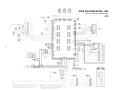
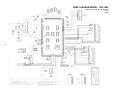
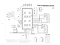
WIRING DIAGRAMS
54
SECTION L:
GENERAL SAFETY PRECAUTIONS
55
SECTION M:
PRE-START-UP
56
SECTION N:
HI-DELTA INITIAL START-UP
60
SECTION O:
POST START-UP CHECK
61
SECTION P:
OPERATION
62
SECTION Q:
MAINTENANCE
64
APPENDIX A: COMBUSTION AIR CONTAMINATION
65
WARRANTY
DANGER:
Make sure the gas on which the boiler will operate is the same type as that specified
on the boiler model and rating plate.
WARNING:
Should overheating occur or the gas supply valve fail to shut, do not turn off or
disconnect the electrical supply to the boiler. Instead, shut off the gas supply at a
location external to the appliance.
WARNING:
Do not use this boiler if any part has been under water. Immediately call a qualified
service technician to inspect the boiler and to replace any part of the control system
and any gas control which has been under water.
WARNING:
To minimize the possibility of improper operation, serious personal injury, fire, or
damage to the boiler, never violate the following safety rules:
1. Always keep the area around the boiler free of combustible materials,
gasoline, and other flammable liquids and vapors.
2. Boiler should never be covered or have any blockage to the flow of fresh air
to the boiler.
WARNING:
Risk of electrical shock. More than one (1) disconnect switch may be required to deenergize the equipment before servicing.
CAUTION:
Operation of this boiler on low temperature systems requires special piping to insure
correct operation.
CAUTION:
If this boiler is to be installed above radiation level, it must be provided with a low
water cutoff device at the time of boiler installation.
CAUTION:
This boiler requires forced water circulation when the burner is operating. See
minimum and maximum flow rates. Severe damage will occur if the boiler is
operated without proper water flow circulation.
CALIFORNIA PROPOSITION 65 WARNING: This product contains chemicals known to the State
of California to cause cancer, birth defects or other reproductive harm.
3
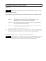
Pay attention to these terms:
DANGER:
indicates the presence of immediate hazards which will cause severe personal injury, death
or substantial property damage if ignored.
WARNING:
indicates the presence of hazards or unsafe practices which could cause severe personal
injury, death or substantial property damage if ignored.
CAUTION:
indicates the presence of hazards or unsafe practices which could cause minor personal
injury or product or property damage if ignored.
NOTICE:
indicates special instructions on installation, operation, or maintenance which are important
but not related to personal injury hazards.
SECTION A: BEFORE INSTALLING THE BOILER
Raypak strongly recommends that this manual be reviewed thoroughly before installing your Raypak boiler. Please review
the General Safety Precautions on Section L before installing the boiler. Factory warranty does not apply to boilers that have
been improperly installed or operated. Installation and service must be performed by a qualified installer, service agency or
gas supplier. If, after reviewing this manual, you still have questions which this manual does not answer, please contact the
factory or your local Raypak representative.
Thank you for purchasing a Raypak product. We hope you will be satisfied with the high quality and durability of our
equipment.
PRODUCT RECEIPT
On receipt of your product it is suggested that you visually check for external damage to the shipping crate. If the crate is
damaged, make a note to that effect on the Bill of Lading when signing for the shipment. Remove the boiler from the shipping
packaging. Report any damage to the carrier immediately.
On occasion, some items will be shipped loose. Be sure that you receive the correct number of packages as indicated on the
Bill of Lading.
Claims for shortages and damages must be filed with the carrier by consignee. Permission to return goods must be received
from the factory prior to shipping. Goods returned to the factory without an authorized Returned Goods Receipt number will
not be accepted. All returned goods are subject to a restocking charge.
When ordering parts, you must specify the Model and Serial Number of the boiler. When ordering under warranty conditions,
you must also specify the date of installation.
Purchased parts are subject to replacement only under the manufacturer's warranty. Debits for defective replacement part
will not be accepted and will be replaced in kind only per Raypak's standard warranties.
4
MODEL IDENTIFICATION
The model identification number and boiler serial number are found on the boiler data plate located on the left inside jacket
of the boiler. The model number will have the form H3 0752 or similar depending on the boiler size and configuration. The first
character of the model number identifies application (H = Hydronic Heating System, W = Hot Water Supply System, P = Pool
Application). The second character identifies the firing mode (3-two stage firing). The next four places identify the size of
the boiler.
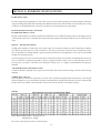
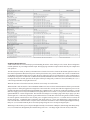
RATINGS AND CERTIFICATIONS
STANDARDS
ANSI Z21.13b-1994, Gas Fired Hot Water Boilers
CAN 3.1 M77; Industrial and Commercial Gas-Fired Package Boilers
ANSI Z21.56-1998<>CSA 4.7-M98 Gas-Fired Pool Heaters
ANSI Z21.10.3-1998<>CSA 4.3-M98 Gas Water Heaters
All Raypak boilers are National Board Approved, design certified and tested by the International Approval Services (IAS)
(a joint venture of American Gas Association Laboratories and the Canadian Gas Association Laboratories) for U.S.A. and
Canada. Each boiler is constructed in accordance with Section IV of the American Society of Mechanical Engineers (ASME)
Boiler Pressure Vessel Code and bears the ASME stamp. This boiler complies with the latest edition of ASHRAE 90.1 Standard.
Altering any RAYPAK pressure vessel by installing replacement heat-exchangers, tube bundle headers, or any other ASME
part not manufactured and/or approved by RAYPAK will instantly void the ASME, AGA, and CGA ratings of the vessel and
any RAYPAK warranty on the vessel. Altering the ASME, AGA and CGA ratings of the vessel also violates national, state,
and local approval codes.
Rated inputs are suitable for up to 4500 feet elevation without derate . Consult the Factory for installations at altitudes in excess
of 4500 feet.
5
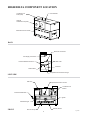
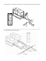
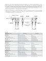
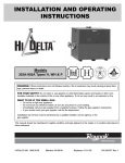
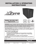
HIGH DELTA COMPONENT LOCATION
Flue Exhaust
Combustion Air
Filter (Inlet)
Optional
Combustion Air (Inlet)
Alternate Flue Connection
BACK
Electrical Connection
Gas Supply Connection
Pressure Relief Connection
Water Inlet
View Port
Water Outlet
Temperature and Pressure Gauge
LEFT-SIDE
Gas Train
Operational Center Control
Combustion Air
Blower
Pressure Relief Valve
Igniter
Heat Exchanger
FRONT
Remote Sensor
Burner Group
6
Fig. #9220
SECTION B: BOILER INSTALLATION
INSTALLATION CODES
Installations must follow these codes:
· Local, state, provincial, and national codes, laws, regulations and ordinances.
· National Fuel Gas Code (NFGC), ANSI Z223.1- latest edition.
· National Electrical Code (NEC), ANSI/NFPA 70 - latest edition.
· Standard for Controls and Safety Devices for Automatically Fired Boilers, ANSI/ASME CSD-1, when required.
· For Canada only: CAN/CGA B149.1 and .2 Installation Code and C.S.A. C22. 1 C.E.C. Part 1.
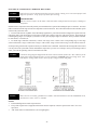
EQUIPMENT BASE
The boiler should be mounted on a level, structurally sound surface as required by code. The boiler is approved for
installation on a combustible surface but must NEVER be installed on carpeting. Gas fueled equipment installed in enclosed
parking garages must be located at least 18 inches above the floor.
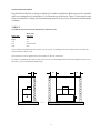
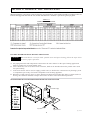
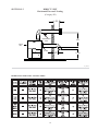
Stacking
Hi Delta units can be stacked two units high with an optional stacking rack. A stacking kit is available from Raypak for this
type of installation.
CAUTION:
The boiler should be located in an area where water leakage will not result in damage to the
area adjacent to the appliance or to the structure. When such locations cannot be avoided, it is
recommended that a suitable catch pan, adequately drained, be installed under the appliance.
The pan must not restrict air flow.
In addition, the boiler shall be installed such that the gas ignition system components are protected from water (dripping,
spraying, rain, etc.) during appliance operation or service (circulator replacement, control replacement, etc.).
Typical Racked Installation
36.0
36.0
12.0
12.0
36.0
TOP VIEW
Fig# 9239
FRONT VIEW
RIGHT SIDE VIEW
7
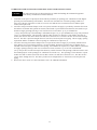
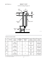
CLEARANCES
TABLE 1
INDOOR INSTALLATION
MINIMUM CLEARANCES FROM COMBUSTIBLE SURFACES
Boiler Side
Floor
Rear
Water Side
Other Side
Top
Front
Vent
Boiler Size
992-2342
See Note 1
1"
12”
1"
1"
1"
2"
Note 1. Do not install on carpeting.
12"
1"
1"
1"
TOP VIEW
Fig. #9221.1
FRONT VIEW
When installed according to the listed minimum clearances from combustible construction materials, the Raypak heaters can still be serviced without removing permanent structural construction around the heater.
However, for ease of servicing, we recommend a clearance of at least 24” in front, and at least
18” on the water connection side. This will enable the heater to be serviced in its installed
location, that is, without movement or removal of the heater.
Clearances less than minimum, may require removal of the heater to service either the heat
exchanger or the burner tray. In either case, the heater must be installed in a manner that will
enable the heater to be serviced without removing any structure around the heater.
8
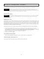
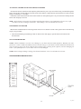
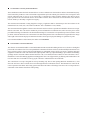
OUTDOOR INSTALLATIONS
Raypak Hi Delta Boilers are design certified by for outdoor installation. Boilers must not be installed
under an overhang that is less than three (3) feet from the top of the boiler. Three (3) sides must be open
in the area under the overhang. Roof water drainage must be diverted away from boilers installed under
overhangs.
TABLE 2
OUTDOOR INSTALLATION MINIMUM CLEARANCES
Boiler Side
Rear
Right
Left
Top
Vent
Boiler Size
992-2342
12"
36”
36"
Unobstructed
N/A
These clearances required where the outdoor vent cap is used. If installing the boiler outdoors with a vent stack, the
indoor clearances may be used.
The air filter box can be installed on top of the boiler or the rear of the boiler.
For outdoor installations especially in snow prone areas, it is recommended that the filter kit be installed on to the rear of
the boiler, to prevent recirculation and blockage.
12"
36"
36"
Fig # 9297
SIDE VIEW
FRONT VIEW
9
SECTION C: COMBUSTION AND VENTILATION AIR
COMBUSTION AND VENTILATION AIR (Indoor Units)
The boiler must be supplied with sufficient quantities of non-contaminated air to support proper combustion and equipment
ventilation. Combustion air can be supplied via conventional venting, where combustion air is drawn from the area immediately surrounding the boiler, or via direct vent, where combustion air is drawn directly from outside. All installations must
comply with the requirements of National Fuel Gas Code for U.S., CAN/CGA B 149.1 and .2 for Canada, and all local codes.
CAUTION:
Combustion air must not be contaminated by corrosive chemical fumes which can damage the boiler
and void the warranty. See appendix A.
NOTICE:
It is recommended that the intake vent be insulated to minimize sweating.
NOTICE:
DIRECT VENT-INSTALLATION
If outside air is drawn through the intake pipe directly to the unit for combustion:
1. Install combustion air direct vent in accordance with Section J-3 and Section J-4
of this manual.
2. Provide for adequate ventilation.
3. In cold climates, and to mitigate potential freeze-up, Raypak highly recommends the installation of a motorized
sealed damper to prevent the circulation of cold air through the boiler during the non-operating hours.
CONVENTIONAL COMBUSTION AIR SUPPLY (FOR U.S. INSTALLATION ONLY)
(a) All Air from Inside the Building. The confined space shall be provided with two permanent openings communicating
directly with an additional room(s) of sufficient volume so that the combined volume of all spaces meets the criteria for an
unconfined space. The total input of all gas utilization equipment installed in the combined space shall be considered in
making this determination. Each opening shall have a minimum free area of 1 square inch per 1,000 Btu per hour (22 cm2 per
kW) of the total input rating of all gas utilization equipment in the confined space, but not less than 100 square inches
(645 cm2). One opening shall commence within 12 inches (30 cm) of the top, and one opening shall commence within 12 inches
(30 cm) of the bottom, of the enclosure. The minimum dimension of air openings shall be not less than 3 inches (8 cm).
(b)All Air from Outdoors. The confined space shall communicate with the outdoors in accordance with methods 1 or 2. The
minimum dimension of air openings shall not be less than 3 in. (8cm). Where ducts are used, they shall be of the same crosssectional area as the free area of the openings to which they connect.
1. Two permanent openings, one commencing within 12in. (30cm) of the top, and one commencing within 12in. (30cm) of
the bottom, of the enclosure shall be provided. The openings shall communicate directly, or by ducts, with the outdoors or
spaces (crawl or attic) that freely communicate with the outdoors.
a. Where directly communicating with the outdoors or where communicating to the outdoors through vertical ducts,
each opening shall have a minimum free area of 1 sq in. per 4000 Btu per hr (5.5cm2 per kW) of total input rating of all
equipment in the enclosure.
b. Where communicating with the outdoors through horizontal ducts, each opening shall have a minimum free area of 1
sq in. per 2000 Btu per hr (11 cm2 per kW) of total input rating of all equipment in the enclosure.
2. One permanent opening, commencing within 12 in. (30cm) of the top of the enclosure, shall be permitted where the
equipment has clearances of at least 1 in. (2.5 cm) from the sides and back and 6 in. (16cm) from the front of the appliance. The
opening shall directly communicate with the outdoors or shall communicate through a vertical or horizontal duct to the
outdoors or spaces (crawl or attic) that freely communicate with the outdoors, and shall have a minimum free area of:
a. 1 sq in. per 3000 Btu per hr (7 cm2 per kW) of the total input rating of all equipment located in the enclosure, and
b. Not less than the sum of the areas of all vent connectors in the confined space.
WARNING:
Do not use one permanent opening method if the equipment room is under negative
pressure condition or the equipment is common vented with other gas-fired appliances.
10
COMBUSTION AND VENTILATION AIR SUPPLY (FOR CANADA INSTALLATION)
CAUTION:
1.
2.
3.
4.
All combustion air has to be drawn from the air outside the building (the mechanical equipment
room directly communicates with the outdoors).
Ventilation of the space occupied by the boiler shall be provided by an opening(s) for ventilation air at the highest
practical point communicating with outdoors. The total cross-sectional area of such an opening(s) shall be at
least 10% of the area required in (2) and (3), but in no case shall the cross-sectional area be less than10 square
inches (6500 square mm).
For boilers using a barometric damper in the vent system, and when air supply is provided by natural air flow from
the outdoors for natural draft, partial fan assisted, fan-assisted or power draft-assisted burners, there shall be a per
manent air supply opening(s) having a cross section area of not less than 1 sq. in. per 7000 BTUH
(310 sq. mm per kW) up to and including 1 million BTUH, plus 1 sq. in. per 14000 BTUH (155 sq. mm per kW) in
excess of 1 million BTUH. This opening(s) shall be either located at or ducted to a point neither more than 18
inches (450 mm) nor less than 6 inches (150 mm) above the floor level. The duct can also "Goose Neck" through
the roof. The duct is preferred straight down 18" from floor, but do not place near piping. This air supply opening
requirement shall be in addition to the air opening for ventilation air required in (1).
For boilers not using a barometric damper in the vent system and when air supply is provided by natural air flow
from outdoors for a power burner and there is no draft regulator, draft hood or similar flue gas dilution device
installed in the same space, in addition to the opening for ventilation air required in (1), there shall be a permanent
air supply opening(s) having a total cross-sectional area of not less than 1 sq. in. for each 30,000 BTUH
(70 sq. mm per kW) of total rated input of the burner(s), and the location of the opening(s) shall not interfere with
the intended purpose of the opening(s) for ventilation air referred to (1). This opening(s) can be ducted to a point
neither more than 18 inches (450 mm) nor less than 6 inches (150 mm) above the floor level. The duct can also
"Goose Neck" through the roof. The duct is preferred to be straight down 18” from floor, but do not place near
piping.
Refer to the latest version of CAN/CGA-B149.1 and .2 for additional information.
11
SECTION D: WATER PIPING - GENERAL
The boiler should be located so that any water leaks will not cause damage to the adjacent area or structures.
CAUTION:
This boiler requires forced water circulation when the burner is operating. See Table D-1 for
minimum and maximum flow rates and water pump selection. The pump must be interlocked with the
boiler to prevent boiler operation without water circulation.
RELIEF VALVE PIPING
WARNING:
Pressure relief valve discharge piping must be piped near the floor close to a floor drain to eliminate
the potential of severe burns. Do not pipe to any area where freezing could occur. Refer to local
codes.
HYDROSTATIC TEST
Unlike many other types of boilers, Raypak boilers do not require hydrostatic testing prior to being placed in operation. The
heat exchanger has already been factory-tested and is rated for 160 PSI operating pressure. However, Raypak does recommend hydrostatically testing the piping connections to the boiler and the rest of the system prior to operation. This is
particularly true for hydronic systems using expensive glycol-based antifreeze. Raypak recommends conducting the hydrostatic test before connecting gas piping or electrical supply.
Leaks must be repaired at once to prevent damage to the boiler. NEVER use petroleum-based stop-leak compounds.
1.
2.
3.
Connect fill water supply. Fill boiler with water (be sure bleed valve is open). When water flows from bleed
valve, shut off water. Close bleed valve. Carefully fill the rest of the system, being sure to eliminate any entrapped air
by using high point vents. Close feed valve. Test at standard operating pressure for at least 24 hours.
Make sure constant gauge pressure has been maintained throughout test.
Check for leaks. Repair if found.
LOW TEMPERATURE SYSTEM
Boiler requires minimum inlet temperature of 105°F. Consult sections E, F for piping details.
TEMPERATURE & PRESSURE GAUGE
The temperature and pressure gauge is factory-mounted in the inlet/outlet header.
12
SECTION E: HYDRONIC HEATING PIPING
PUMP SELECTION
In order to insure proper performance of your boiler system, you must install a properly sized pump. Raypak recommends
using a 20°F∆T as design ∆T. (∆T is the temperature difference between the inlet and outlet water when the boiler is firing
at full rate). If a ∆T larger than 20°F is necessary, see Table D-1 for minimum flow rate requirements.
PRESSURE DROP IN FEET OF HEAD
FEEDWATER REGULATOR
Raypak recommends that a feedwater regulator be installed and set at 12 PSIG minimum pressure at the highest point of
system. Install a check valve or back flow device upstream of the regulator, with a manual shut off valve as required by local
codes.
PIPING - HEATING BOILERS
All high points should be vented. Purge valves and a bypass valve should be installed. A boiler installed above radiation
level must be provided with a low water cutoff device. The boiler, when used in connection with a refrigeration system,
must be installed so the chilled medium is piped in parallel with the boiler with appropriate valves to prevent the chilled
medium from entering the boiler.
The boiler piping system of a hot water heating boiler connected to heating coils located in air handling units where they
may be exposed to circulating refrigerated air, must be equipped with flow control valves or other automatic means to
prevent gravity circulation of the boiler water during the cooling cycle. It is highly recommended that the piping be
insulated.
AIR-SEPARATION/EXPANSION TANK
All boilers should be equipped with a properly sized expansion tank and air separator fitting as shown in the following
diagrams.
THREE-WAY VALVES
Valves designed to blend water temperatures or reduce water circulation through the boiler should not be used. Raypak
heaters are high recovery low mass heaters not subject to thermal shock. Raypak offers a full line of electric sequencers that
produce direct reset of boiler water temperature. Refer to the Controls Section in our Complete Catalog.
Table D-1
NOTE: Basis forMinimum flow - 30 gpm or 40° DT.
Maximum flow - 132 gpm
Flow switch will not operate if flow is less than 20 gpm.
13
SINGLE BOILER - LOW TEMPERATURE APPLICATION (HEAT PUMP) PRIMARY/SECONDARY PIPING
12
Fig. #9223
DUAL BOILER PRIMARY/SECONDARY PIPING
Fig. #9232.2
14
SECTION F: DOMESTIC HOT WATER PIPING
When designing the water piping system for domestic water applications, water hardness should be considered. Table F-1
indicates the suggested flow rates for soft, medium and hard water. Hardness is specified as grains per gallon.
TABLE F-1
DOMESTIC WATER HEATER
FLOW RATE REQUIREMENTS
* Must use optional cupronickel tubes.
POTABLE WATER AND SPACE HEATING APPLICATION
CAUTION:
When this heater is used for both -potable water and space heating- follow the steps below
to insure proper operation.
A. All piping materials and components connected to the water heater for the space heating application
shall be suitable for use with potable water.
B. Toxic chemicals, such as used for boiler treatment, shall not be introduced into the potable water used
for space heating.
C. If the water heater will be used to supply potable water, it shall not be connected to any heating system
or components previously used with a nonpotable water heating appliance.
D. When the system requires water for space heating at temperatures higher than 140°F, a means such as a
mixing valve shall be installed to temper the water in order to reduce scald hazard potential.
SINGLE DOMESTIC HOT WATER HEATER WITH ONE STORAGE TANK
Hot Water Supply
City Water
System Return
15
Fig. #9224.1
SECTION G: POOL HEATING
CAUTIO
CAUTION:
Power to the heater should be interlocked with the main system pump to make sure the heater does not fire
without the main system pump in operation. Improper flow control can damage the heater. Uncontrolled
flow (too high) or restricted flow (too low) can seriously damage the heater. Follow these instructions to
make sure your heater is properly installed.
The Hi-Delta pool heater is equipped with an external pump and bypass arrangement that blends outlet water with the inlet
to increase the inlet water temperature, thereby reducing the likelihood of condensation forming on the heat exchanger. The
pump also serves to circulate water through the heater form the main system piping.
To complete the installation of the pool heater, the pool thermostat needs to be installed in the main return water line. This
will insure that the heater will be energized at the right time. If the main water line is too far away from the heater and the
capillary bulb will not reach it, locate the pool thermostat adjacent to the main line and run wires back to the heater. See
Figure #9225.
Adjustment of the bypass valve is critical to proper operation of the heater. The bypass valve should be adjusted to achieve
an inlet water temperature of 100°F and an outlet water temperature between 120°F and 140°F. When starting with a cold pool,
make initial adjustments. Make final adjustments when pool water approaches desired temperature.
H BYPASS
16
AUTOMATIC CHLORINATORS AND CHEMICAL FEEDERS
All chemicals must be introduced and completely diluted into the pool or spa water before being circulated through the
heater. Do not place chlorine tablets or bromine sticks in the skimmer. High chemical concentrations will result when the
pump is not running (i.e. overnight).
Chlorinators must feed downstream of the heater and have an anti-siphoning device to prevent chemical backup into the
heater when the pump is shut off.
NOTE: High chemical concentrates from feeders and chlorinators that are out of adjustment will cause very rapid
corrosion to the heat exchanger in the heater. Such damage is not covered under the warranty.
WINTERIZING YOU HEATER
When heaters installed outdoors in freezing climate areas are to be shut down for the winter, please observe the following
step-by-step procedure:
1. Turn off manual main gas and main gas shut off. Remove the drain plug or open the drain cock located on the
bottom header.
SPA WATER CHEMISTRY
NOTE: Chemical imbalance can cause severe damage to your heater and associated equipment. Maintain your water
pH between 7.4 and 7.8 and total alkalinity between 100 and 150 p.p.m. If the mineral content and dissolved solids in the
water become too high, scale forms inside the heat exchanger tubes, reducing heater efficiency and also damaging the
heater. If the pH drops below 7.2, the heater will be severely damaged.
NOTE: Heat exchanger damage resulting from chemical imbalance is not covered under the warranty.
SINGLE POOL HEATER APPLICATION
17
Fig. #9225
SECTION H: GAS SUPPLY CONNECTIONS
DANGER:
Make sure the gas on which the boiler will operate is the same type as specified on the boiler
model and rating plate.
Gas piping must have a sediment trap ahead of the boiler gas controls, and a manual shut-off valve located outside the
heater jacket. A pounds to inches regulator must be installed to reduce to gas supply pressure to under 14" W.C. The
regulator should be placed a minimum distance of 10 times the pipe diameter upstream of the boiler gas controls. All gas
piping must be tested after installation in accordance with local codes. The boiler and its gas connection must be leak-tested
before placing it in operation.
Fig. #9226.1
GAS SUPPLY CONNECTION
CAUTION:
The boiler and its manual shutoff valve must be disconnected from the gas supply during any pressure
testing of the gas supply system at test pressures in excess of 1/2 PSIG (3.45 KPA). The boiler must be
isolated from the gas supply piping system by closing the manual shutoff valve during any pressure
testing of the gas supply piping system at test pressures equal to or less than 1/2 PSIG. Relieve test
pressure in the gas supply line before reconnecting the boiler and its manual shut off valve to the gas
supply line. FAILURE TO FOLLOW THIS PROCEDURE MAY DAMAGE THE GAS VALVES. Over
pressurized gas valves are not covered by warranty. The boiler and its gas connections shall be leak tested
before placing the appliance in operation. Use soapy water for leak test: DO NOT use open flame.
CAUTION:
Do not use Teflon tape on gas line pipe thread. A pipe compound rated for use with gas systems is
recommended. Apply sparingly only on male pipe ends.
CAUTION:
Support gas supply piping with hangers, not by the boiler or its accessories. Ensure the gas piping is
protected from physical damage and freezing where required.
GAS SUPPLY PRESSURE
A minimum of 7” W.C. and a maximum of 14” W.C. upstream gas pressure is required under load and no load conditions
for natural gas. A minimum of 12” W.C. and a maximum of 14” W.C. is required for propane gas. The gas pressure
regulator supplied on the boiler is for low pressure service. If upstream pressure exceeds 14" W.C, an intermediate gas
pressure regulator, of the lockup type, must be installed.
When connecting additional gas utilization equipment to the gas piping system, the existing piping must be checked to
determine if it has adequate capacity.
18
GAS PRESSURE REGULATOR
The gas valve pressure regulator(s) on the boiler are nominally preset at 3.5" W.C. for Natural gas, and 10.5" W.C. for
Propane gas manifold pressure. The pressure at the gas valve outlet tap, measured with a manometer,while in operation
should be 3.5 ± 0.1" W.C. for Natural gas and 10.5" ± 0.1" W.C. for Propane gas. If an adjustment is needed, turn the
adjustment screw clockwise to increase pressure or counter-clockwise to lower pressure.
19
SECTION I: ELECTRICAL POWER CONNECTIONS
Installations must follow these codes:
·
·
·
·
National Electrical Code and any other national, state, provincial or local codes or regulations having
jurisdiction.
Safety wiring must be N.E.C. Class 1.
Boiler must be electrically grounded as required by N.E.C. ANSI/NFPA 70-latest edition.
In Canada, C.S.A. C22. 1 C.E.C. Part 1.
The boiler is wired for 120 Volts, 12 AMPS. The voltage is indicated on the tie-in leads. Consult the wiring diagram shipped
with the boiler in the instruction packet. The remote tank control stat, thermostat, or electronic boiler control as applicable,
may be connected to the stage selector (See wiring diagram). 24 Volts are supplied to this connection through the boiler
transformer. DO NOT attach line voltage to the “TH” leads. Before starting the boiler check to insure proper voltage to the
boiler and pump.
Install a separate disconnect means for each load. Use appropriate-sized wire as defined by NEC, CSA and/or local code. All
primary wiring should be 125% of minimum rating.
It is strongly recommended that all individually-powered control modules and the boiler should be supplied from the same
power source.
SURGE PROTECTION
Microprocessor-based and solid state controls are vulnerable to damage from voltage and amperage fluctuations in the
power supply. All sensitive control components should be protected by a suitable commercial-grade surge protection device.
If any of the original wire as supplied with the boiler must be replaced, it must be replaced with 105°C wire or its equivalent.
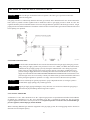
CHECK THE POWER SOURCE
WARNING:
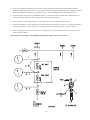
Using a volt-ohm meter (VOM), check the following voltages at the circuit breaker panel prior to
connecting any equipment: Make sure proper polarity is followed and house ground is proven.
FIGURE I-1
CHECK POWER SOURCE
BLACK
CIRCUIT
BREAKER
VOLT-OHM
METER
WHITE
GREEN
GROUND
A B
C
Fig. # 9237
AC = 108 Volts AC Minimum, 132 Volts AC MAX
AB = 108 Volts AC Minimum, 132 Volts AC MAX
20
MAKING THE ELECTRICAL CONNECTIONS
Refer to Fig. #9227 Wiring Connection, and Fig. #9233 or Fig. #9234 Wiring Diagram.
1.
2.
3.
4.
5.
6.
7.
Verify circuit breaker is properly sized by referring to boiler rating plate. A dedicated circuit breaker should be
provided.
Turn off all power to the boiler. Verify that power has been turned off by testing with a volt-ohm meter prior to
working with any electrical connections or components.
Observe proper wire colors while making electrical connections. Many electronic controls are polarity sensitive.
Components damaged by improper electrical installation are not covered by warranty.
Provide an external surge suppressor capable of maintaining system integrity.
Provide overload protection and a disconnect means for equipment serviceability as required by local and state code.
Install boiler controls, thermostats, or building management systems in accordance with the applicable manufacturer’s
instructions.
Conduit should not be used as the ground. There must be a solidly wired ground.
NOTICE:
A grounding electrode conductor shall be used to connect the equipment grounding conductors,
the equipment enclosures, and the grounded service conductor to the grounding electrode.
FIELD WIRING CONNECTION
MAIN POWER AND
PUMP POWER IN
(ALTERNATE LOCATION
AT OTHER END)
ALTERNATE POWER
IN LOCATIONS
Fig. #9227
21
ELECTRICAL CONNECTIONS - DOMESTIC HOT WATER
CAUTION:
Label all wires prior to disconnection when servicing controls. Wiring errors can cause improper and
dangerous operation. Verify proper operation after servicing.
DANGER
- SHOCK HAZARD
Make sure electrical power to the heater is disconnected to avoid potential serious injury or damage to
components.
Installer action is required to electrically enable your Hi-Delta boiler to operate after making the power conections. You must
make a connection on the stage selector for temperature control connection. This will be done based on the controller option
selected with your boiler order.
1. For Pool and Closed Loop Water Source Heat Pump applications, your boiler should be configured to operate in an ON/
OFF firing mode. This means that you will connect a single-pole control to stage one of the stage selector. Then jumper the
remaining firing stages. For example, if your boiler is a 992, you will jumper stages two and three. Then your boiler will either
be on at full fire, or it will be off.
2. For multi-stage controller connections, connect each stage of the control to the corresponding stage of the stage
selector in the boiler. Stage 1 of the boiler to stage 1 of the control. Stage 2 of the boiler to stage 2 of the control, and so on.
Set the operating control at the setpoint in which you want the boiler to maintain. Ensure that the sensing bulb of the control
is at the point in the system that will best maintain the temperature you want. For example, when you are heating a tank of
water, you want the operating control sensor bulb in the tank.
CAUTION:
Consult the wiring diagram shipped with the boiler in the instruction packet. The “TH” leads are for the
remote tank control through the boilers 24 volt transformer. DO NOT attach line voltage to the “TH”
leads. Before starting boiler check to insure proper voltage to boiler and pump.
Fig. #9138.2
NOTICE:
Fig. #9138.1
Boiler must be electrically grounded in accordance with National Electrical Code ANSI/NFPA No.70,
and CSA C22.1 C.E.C. Part 1 in Canada.
NOTES:
1. Field installed ground to inside of junction box.
2. If any of the original wire as supplied with the boiler must be replaced, it must be replaced with 105°C wire or its
equivalent.
3. “TH” leads connect to terminal block 3 (See wiring diagram).
22
SECTION J: VENTING CONNECTIONS
GENERAL
CAUTION:
Proper installation of flue exhaust venting is critical for the safe and efficient operation of the boiler.
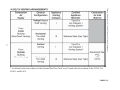
Definition of Appliance Categories
Boilers are divided into four categories based on the pressure produced in the exhaust and the likelihood of condensate
production in the vent.
Category I.
A boiler which operates with a non-positive vent static pressure and with a vent gas
temperature that avoids excessive condensate production in the vent.
Category II.
A boiler which operates with a non-positive vent static pressure and with a vent gas
temperature that may cause excessive condensate production in the vent.
Category III.
A boiler which operates with a positive vent pressure and with a vent gas temperature that
avoids excessive condensate production in the vent.
Category IV.
A boiler which operates with a positive vent pressure and with a vent gas temperature that
may cause excessive condensate production in the vent.
See Table J-1 for appliance category requirements for the Hi-Delta.
Note:
For additional information on appliance categorization, see appropriate ANSI Z21 Standard and the latest
edition Standard of National Fuel Gas Code or in Canada, the latest edition of CGA Standard B149 Installation
Code for Gas Burning Appliances and Equipment, or applicable provisions of local building codes.
Determination of Appliance Category for Venting Purposes and Venting Arrangements
WARNING:
Contact the manufacturer of the vent material if there is any question about the appliance categorization and suitability of a vent material for application on a Category III or IV vent system. Using
improper venting materials can result in personal injury, death or property damage.
23
Category Determination for Venting Purpose and Venting Arrangement
24
* As defined in the latest edition of the National Fuel Gas Code, or in Canada, the latest edition of the CAN/CGA
B149.1 and B149.2.
TABLE J-1
Support of Vent Stack
The weight of the vent stack or chimney must not rest on the boiler vent connection. Support must be provided in compliance with applicable codes. The vent should also be supported to maintain proper clearances from combustible materials.
Use insulated vent pipe spacers where the vent passes through combustible roofs and walls.
Vent Terminal Location
NOTICE:
During winter months check the vent cap and make sure no blockage occurs from build up of snow.
Condensate can freeze on the vent cap. Frozen condensate on the vent cap can result in a blocked
flue condition.
General
Give special attention to the location of the vent termination to avoid possibility of property damage or personal injury.
a) Gases may form a white vapor plume in winter. The plume could obstruct a window view if the termination is installed
in close proximity to windows.
b) Prevailing winds could cause freezing of condensate and water/ice build-up on building, plants or roof.
c) The bottom of the vent terminal and the air intake shall be located at least 12 inches above grade.
d) Un-insulated single-wall metal vent pipe shall not be used outdoors on cold climates for venting gas utilization equipment.
e) Through-the-wall vents for Category II and IV appliances and non-categorized condensing appliances shall not terminate over public walkways or over an area where condensate or vapor could create a nuisance or hazard or could be
detrimental to the operation of regulators, relief valves, or other equipment. Where local experience indicates that
condensate is a problem with Category I and III appliances, this provision shall also apply.
f) Locate and guard vent termination to prevent accidental contact by people or pets.
g) DO NOT terminate vent in window well, stairwell, alcove, courtyard or other recessed area, unless previously approved by local authority.
h) DO NOT terminate above any door, window, or gravity air intake. Condensate can freeze, causing ice formations.
i) Locate or guard vent to prevent condensate from damaging exterior finishes. Use a 2’ x 2’ rust resistant sheet metal
backing plate against brick or masonry surfaces.
j) DO NOT extend exposed vent pipe outside of building. Condensate could freeze and block vent pipe.
US Installations - Refer to latest edition of National Fuel Gas Code
Vent termination requirements are as follows:
a) Vent must terminate at least four (4) feet below, four (4) feet horizontally, or one (1) foot above any door, window or
gravity air inlet to the building.
b) The vent must not be less than seven (7) feet above grade when located adjacent to public walkways.
c) Terminate vent at least three (3) feet above any forced air inlet located within ten (10) feet.
d) Vent must terminate at least four (4) feet horizontally, and in no case above or below unless four (4) feet horizontal
distance is maintained, from electric meters, gas meters, regulators, and relief equipment.
e) Terminate vent at least six (6) feet away from adjacent walls.
f) DO NOT terminate vent closer than five (5) feet below roof overhang.
g) The vent terminal of a direct vent appliance with an input over 50,000 Btu per hour shall require a 12-inch vent
terminal clearance.
h) Terminate vent at least one (1) foot above grade, including normal snow line.
i) Multiple direct vent installations require a four (4) foot clearance between vent caps.
25
Canada Installations - Refer to latest edition of CAN/CGA-B149.1 and .2
A vent shall not terminate:
a) Directly above a paved sidewalk or driveway which is located between two single family dwellings and serves both
dwellings
b) Less than 7 ft.(2.13m)above a paved sidewalk or paved driveway located on public property
c) Within 6 ft(1.8m) of a mechanical air supply inlet to any building
d) Above a meter/regulator assembly within 3 ft(900mm) horizontally of the vertical centre-line of the regulator
e) Within 6 ft.(1.8m) of any gas service regulator vent outlet
f) Less than 1 ft.(300mm) above grade level
g) Within the 3 ft.(1m) of a window or door which can be opened in any building, any non-mechanical air supply inlet to
any building or the combustion air inlet of any other appliance
h) Underneath a verandah, porch or deck, unless
(i) the verandah, porch or deck is fully open on a minimum of two sides beneath the floor, and
(ii)the distance between the top of the vent termination and the underside of the verandah, porch or deck is
greater than 1 ft(25cm).
Venting Installation Tips
Support piping:
·
horizontal runs- at least every five (5) feet (Canada - every three (3) feet).
·
vertical runs - use braces:
·
under or near elbows
Follow items listed below to avoid personal injury or property damage.
·
·
·
·
Cut nonmetallic intake pipe with fine-toothed hacksaw (34 teeth per inch).
Do not use nonmetallic intake pipe or fittings that are cracked or damaged.
Do not use nonmetallic intake fittings if they are cut or altered.
Do not drill holes, or use screws or rivets, in nonmetallic intake pipe or fittings.
To make metallic vent joints:
·
Do not install seams of vent pipe on bottom of runs.
·
100% Seal all joints and seams with silicone sealant.
WARNING:
Examine the venting system at least once a year. Check all joints and vent pipe connections for
tightness, corrosion or deterioration.
NOTE: The words "Flue Exhaust", "Flue" and "Exhaust Vent" are used interchangeably.
VENTING CONFIGURATIONS
For boilers connected to gas vents or chimneys, vent installations shall be in accordance with Part 7, Venting of Equipment,
of the latest edition of National Fuel Gas Code, or in Canada, the latest edition of CAN/CGA-B149.1 and .2 Installation
Code for Gas Burning Appliances and Equipment, or applicable provisions of local building codes.
26
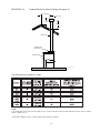
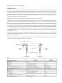
SECTION J-1
Natural Draft Vertical Venting (Category I)
10' OR LESS
VENT CAP
2' MIN
2' MIN
VENT PIPE
COMBUSTION
AIR FILTER
BOILER UNIT
Fig. #9228
NATURAL DRAFT VERTICAL VENT
*
NOTE:
**Vent lengths are based on a lateral length of 2 feet. Refer to the latest edition of the National Fuel Gas Code for further
details. (ANSI Z223.1)
* Barometric damper must be a single acting listed barometric damper.
27
♦ Natural Draft Vertical Venting System Installation
Natural draft venting uses the natural buoyancy of the heated flue products to create a thermal driving head that expels the
exhaust gases from the flue. The negative draft must be within the range of -.01” to -.10” negative W.C. as measured 12
inches from the appliance flue outlet to insure proper operation. Vent material must be listed by a nationally recognized
test agency.
The maximum and minimum venting length for Category I appliance shall be determined per the latest edition of the National
Fuel Gas Code (U.S.) or B149.1 and .2 Installation Code (Canada).
The diameter of vent flue pipe should be sized according to Part 11 of the latest edition of the National Fuel Gas Code
(U.S.) and part 7 and appendix B of the CAN/CGA-B149.1 and .2 installation code (Canada). The minimum flue pipe
diameter for conventional negative draft venting using double-wall B type vent is 10” for 992, 12” for 1262-1532,14” for 18022072 and 16" for 2342.
NOTICE:
Vent Adapter will have to be used to connect B vent to the unit.
The connection from the appliance vent to the stack must be as direct as possible and shall be the same diameter as, or
larger than the vent outlet. The horizontal breaching of a vent must have an upward slope of not less than 1/4 inch per linear
foot from the boiler to the vent terminal. The horizontal portions of the vent shall also be supported for the design and weight
of the material employed to maintain clearances and to prevent physical damage or separation of joints.
♦ Natural Draft Vertical Vent Termination
The vent terminal should be vertical and should terminate outside the building at least two (2) feet above the highest point
of the roof that is within 10 feet. The vent cap should have a minimum clearance of four (4) feet horizontally from and in
no case above or below (unless a four (4) foot horizontal distance is maintained) electric meters, gas meters, regulators and
relief equipment. The distance of the vent terminal from adjacent public walkways, adjacent buildings, open windows and
building openings must be consistent with the National Fuel Gas Code, or in Canada, the latest edition of CAN/CGA-B149
Installation Code for Gas Burning Appliances and Equipment. Gas vents supported only by flashing and extended above
the roof more than five feet should be securely guyed or braced to withstand snow and wind loads.
CAUTION:
Listed vent cap terminal must be used and sized adequately to evacuate the flue products from the
boilers.
♦ Natural Draft Vertical Venting With Common Venting System, Category I Appliance Only
Manifolds that connect more than one boiler to a common chimney must be sized to handle the combined load. Consult
available guides for proper sizing of the manifold and the chimney. At no time should the area of the vent be less than the
area of the largest boiler exhaust outlet.
WARNING:
CAUTION:
Vent connectors serving appliances vented by natural draft shall not be connected into any portion of
mechanical draft systems operating under a positive pressure.
Vent connectors for natural draft venting systems must be type “B” vent or better.
28
Common venting systems may be too large when an existing unit is removed. At the time of removal of an existing appliance, the following steps must be followed with each appliance remaining connected to the common venting system placed
in operation, while the other appliances remaining connected to the common venting system are not in operation.
a) Seal any unused opening in the common venting system.
b) Visually inspect the venting system for proper size and horizontal pitch and determine there is no blockage or
restriction, leakage, corrosion or other unsafe condition.
c) Insofar as is practical, close all building doors and windows and all doors between the space in which the appliances remaining connected to the common venting system are located and other spaces of the building. Turn on
clothes dryers and any appliance not connected to the common vent system. Turn on any exhaust fans, such as
range hoods and bathroom exhausts, so they will operate at maximum speed. Do not operate summer exhaust fan.
Close fireplace dampers.
d) Place in operation the appliances being inspected. Follow the manufacturers instructions for lighting each appliance. Adjust thermostat so appliance will operate continuously.
e) Test for spillage at the draft hood relief opening after 5 minutes of main burner operation. Use the flame of a match
or candle, or smoke from a cigarette, cigar or pipe, toilet paper trick. For the Hi-Delta, check the pressure at a
pressure tap located 12 inches above the bottom joint of the first vertical vent pipe. Pressure should be anywhere
between 0 to -.1 inch water column.
f) After it has been determined that each appliance remaining connected to the common venting system properly
vents when tested as outlined above, return doors, windows, exhaust fans, fireplace dampers and other gas burning
appliances to their previous conditions of use.
g) Any improper operation of the common venting system should be corrected so that the installation conforms with
the latest edition of the National Fuel Gas Code, ANSI Z223.1, in Canada, the latest edition of CAN/CGA-B 149.1
and .2 Installation Code for Gas Burning Appliances and Equipment. When re-sizing any portion of the common
venting system, the common venting system should be re-sized to approach the minimum size as determined using
the appropriate tables in Appendix G in the latest edition of the National Fuel Gas Code, ANSI Z223.1, in Canada,
Appendix B of the latest edition of the Installation Code for Gas Burning Appliances and Equipment.
29
SECTION J-2
Horizontal Thru-Wall Venting (Category III)
Fig. #9229.1
HORIZONTAL THRU-WALL VENTING (CATEGORY III) TABLE
♦ Horizontal Thru-wall Venting System (Category III) Installation
These installations utilize the boiler-mounted blower to vent the combustion products to the outdoors. Combustion air is
taken from inside the room and the vent is installed horizontally through the wall to the outdoors. Adequate combustion and
ventilation air must be supplied to the boiler room in accordance with the National Fuel Gas Code or, in Canada, the latest
edition of CAN/CGA-B149.1 and .2 Installation Code for Gas Burning Appliances and Equipment.
30
The total length of the horizontal thru-wall exhaust vent system should not exceed seventy (70) feet in length. If horizontal
run exceeds 70 feet, an appropriately sized extractor must be used. To maintain proper operation pressure reading must be
between -.01 to -.1 W.C. as measured 12 inches from the appliance flue outlet. Each elbow used is equal to ten (10) feet of
straight pipe. This will allow installation in one of the four following combinations.
·
·
·
·
70’ of straight flue pipe.
60' of straight flue pipe and one elbow.
50' of straight flue pipe and two elbows.
40' of straight pipe and three elbows.
The vent cap is not considered in the overall length of the venting system.
The vent must be installed to prevent the flue gas leakage. Care must be taken during assembly to insure that all joints are
sealed properly and are airtight.
The vent must be installed to prevent the potential accumulation of condensate in the vent pipes. It is recommended that:
a) The vent be installed with a slight downward slope of not more than 1/4" per foot of horizontal run to the vent terminal.
b) The vent be insulated through the length of the horizontal run.
For appliances installed in extreme cold climate, it is recommended that:
a) The vent be installed with a slight upward slope of not more than 1/4" per foot of horizontal run to the vent terminal.
In this case, an approved condensate trap must be installed per applicable codes.
b) The vent be insulated through the length of the horizontal run.
A sleeve has been added inside the flue box of all Hi Delta heaters, as a redundant heat insulator to eliminate internal
condensation. It is to be removed only when the application calls for venting through the rear of the unit.
To remove sleeve, remove the rear exhaust cover panel and lift sleeve upward. Note: The sleeve is not mechanically
attached, and will lift upward with a rocking motion. Use a knife or razor blade to cut through and loosen the RTV
sealant.
HI DELTA SLEEVE FLUE CONVERSION
Fig. #9436
31
♦ Horizontal Thru-wall Direct Vent Termination
The flue exhaust direct vent cap MUST be mounted on the exterior of the building. The direct vent cap cannot be installed in
a well or below grade. The direct vent cap must be installed at least one (1) foot above ground level and above normal snow
levels. The Raypak supplied flue exhaust direct vent cap must be utilized.
WARNING:
No substitutions of flue pipe or vent cap material are allowed. Such substitutions would jeopardize the
safety and health of inhabitants.
The Stainless Steel direct vent cap must be furnished by the boiler manufacturer in accordance with its
listings.
Use only the special gas vent pipes listed for use with category III gas burning heaters, such as the stainless steel Saf-T vent
by Heat Fab Inc. (413-744-2356). Pipe joints must be positively sealed. Follow carefully the vent manufacturers installation
instructions.
32
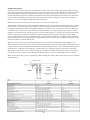
SECTION J-3
DIRECT VENT
Horizontal Thru-wall Venting
(Category III)
9"
MIN.
36"
MIN.
CONDENSATE
TRAP
BOILER
UNIT
FILTER
6"
MIN.
12" MIN.
Fig. #9230.1
HORIZONTAL THRU-WALL VENTING TABLE
33
♦ Horizontal Thru-wall Direct Vent System (Category III) Installation
These installations utilize the boiler mounted blower to draw combustion air from outdoors and vent combustion products to
the outdoors.
The total length of the thru-wall exhaust vent cannot exceed forty (40) feet in length for the flue outlet. Each elbow used is
equal to ten (10) feet of straight pipe. This will allow installation in one of the three following combinations.
·
·
·
40’ of straight combustion air pipe.
30' of straight combustion air pipe and one elbow.
20' of straight combustion air pipe and two elbows.
The total length air supply pipe cannot exceed forty (40) feet in length for the combustion air inlet. Each elbow used is equal
to ten (10) feet of straight pipe. This will allow installation in one of the three following combinations.
·
·
·
40’ of straight flue pipe
30' of straight flue pipe and one elbow.
20' of straight flue pipe and two elbows.
The flue exhaust direct vent cap is not considered in the overall length of the venting system.
Care must be taken during assembly that all joints are sealed properly and are airtight.
The vent must be installed to prevent the potential accumulation of condensate in the vent pipes. It is recommended that:
a) The vent be installed with a slight downward slope of not more than 1/4" per foot of horizontal run to the vent terminal.
b) The vent be insulated through the length of the horizontal run.
For appliances installed in extreme cold climate, it is recommended that:
a) The vent be installed with a slight upward slope of not more than 1/4" per foot of horizontal run to the vent terminal. In
this case, an approved condensate trap must be installed per applicable codes.
b) The intake vent be insulated through the length of the horizontal run.
♦ Horizontal Thru-wall Direct Vent Termination
The flue exhaust direct vent cap MUST be mounted on the exterior of the building. The direct vent cap cannot be installed in
a well or below grade. The direct vent cap must be installed at least one (1) foot above ground level and above normal snow
levels.
Multiple direct vent caps MUST NOT be installed with one combustion air inlet directly above a direct vent cap. This
vertical spacing would allow the flue products from the direct vent cap to be pulled into the combustion air intake installed
above. This type of installation can cause non warrantable problems with components and poor operation of the unit due to
the recirculation of flue products. Multiple direct vent caps should be installed in the same horizontal plane with a three (3)
foot clearance from the side of one vent cap to the side of the adjacent vent cap(s).
Combustion air supplied from outdoors must be free of particulate and chemical contaminants. To avoid a blocked flue
condition, keep the vent cap clear of snow, ice, leaves, debris, etc.
WARNING:
No substitutions of flue pipe or vent cap material are allowed. Such substitutions would jeopardize the
safety and health of inhabitants.
The Stainless Steel flue exhaust direct vent cap must be furnished by the boiler manufacturer in accordance with its listings.
Use only the special gas vent pipes listed for use with category III gas burning heaters, such as the stainless steel Saf-T vent
by Heat Fab Inc. (800-772-0739). Pipe joints must be positively sealed. Follow carefully the vent manufacturers installation
instructions.
34
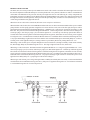
DIRECT VENT
SECTION J-4
Vertical Venting (Category I)
3'
MIN.
VENT
CAP
3' MIN.
1' MIN.
INTAKE VENT
EXHAUST
VENT
BOILER
UNIT
AIR FILTER
Fig. #9231.1
VERTICAL VENTING TABLE
35
♦ Vertical Direct Vent System Installation
These installations utilize the boiler mounted blower to draw combustion air from outdoors and uses the natural buoyancy
of the heated flue products to create a thermal driving head that expels the exhaust gases from the flue. The negative draft
must be within the range of -0.01 to -0.10” negative W.C. as measured 12 inches from the appliance flue outlet to insure
proper operation. The vent material must be in accordance with the above instructions for vent materials. Vent material
must be listed by a nationally recognized test agency.
The maximum and minimum venting length for Category I appliance shall be determined per the latest edition of the
National Fuel Gas Code (U.S.) and CAN/CGA-B149.1 and .2 Installation Code (Canada).
The connection from the appliance exhaust vent to the stack must be as direct as possible and should be the same as or larger
than the vent outlet. The vent must be installed to prevent accumulation of condensate and, where necessary, have means
provided for drainage of condensate. The horizontal breaching of a vent must have an upward slope of not less than 1/4 inch
per linear foot from the boiler to the vent terminal. The horizontal portions of the vent shall also be supported for the design
and weight of the material employed to maintain clearances and to prevent physical damage or separation of joints.
It is recommended that in colder climates, the intake vent be insulated.
♦ Vertical Direct Vent Termination
The exhaust vent terminal should be vertical and should terminate outside the building at least two (2) feet above the highest
point of the roof within 10 feet. The vent cap should have a minimum clearance of four (4) feet horizontally from and in no case
above or below (unless a four (4) foot horizontal distance is maintained) electric meters, gas meters, regulators and relief
equipment. The distance of the vent terminal from adjacent public walkways, adjacent buildings, open windows and building
openings must be consistent with the National Fuel Gas Code, or in Canada, the latest edition of CAN/CGA-B149.1 and .2.
Installation Code for Gas Burning Appliances and Equipment. Gas vents supported only by flashing and extended above the
roof more than five feet should be securely guyed or braced to withstand snow and wind loads.
The vertical direct vent cap is designed for roof top mounting only. The air inlet opening MUST be installed one (1) foot
above the roof line or above normal snow levels that might obstruct combustion air flow. This dimension is critical to the
correct operation of the boiler and venting system and reduces the chance of blockage from snow. The vent cap must have
a minimum 3 foot clearance from the air inlet opening.
36
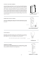
SECTION J-5
Outdoor Installation
Outdoor models are self -venting when installed with the factory-supplied restricted direct vent cap and require no additional vent piping. This special vent cap is provided with the boiler in accordance with AGA/CGA requirements. It must be
installed directly on the boiler. See Section B for correct clearances.
Care must be taken when locating the outdoor unit because the flue gases discharged from the vent hood can condense as
they leave the hood. Improper location can result in damage to adjacent structures or building finish. For maximum efficiency
and safety, the following precautions must be observed:
a) Outdoor models must be installed outdoors and must use the outdoor vent hood supplied by the manufacturer.
b) Periodically check venting system. The boiler’s venting areas must never be obstructed in any way and minimum
clearances must be observed to prevent restriction of combustion and ventilation air. Keep area clear and free of
combustible and flammable materials.
c) Do not locate adjacent to any window, door walkway, or gravity air intake. The vent must be located a minimum of
four (4) feet horizontally, or four (4) feet below, or one (1) foot above such areas.
d) Install above grade level and above normal snow levels.
e) Vent terminal must be at least 3 feet above any forced air inlet located within 10 feet.
f) Adjacent brick or masonry surfaces must be protected with a rust-resistant sheet metal plate.
g) Multiple Outdoor Vent installations require a four (4) feet clearance between vent caps.
h) On racked outdoor installations- Outdoor vent termination of the lower boiler should at least be as high as the upper
boiler vent termination.
NOTICE:
Condensate can freeze on the vent cap. Frozen condensate on the vent cap can result in a blocked flue
condition.
NOTICE:
On snow prone areas it is recommended that the combustion air terminal be located on the rear of the
appliance to minimize snow blockage.
NOTICE:
For the model 992 outdoor installation, the air intake terminal must not be installed on the same plane
as the vent terminal.
The restricted vent cap must be furnished by the boiler manufacturer in accordance with its listings.
An outdoor air filter, supplied by the manufacturer is mounted on the boiler.
HI DELTA OUTDOOR VENT KITAND INSTRUCTIONS
NOTICE:
These instructions are intended for use by qualified personnel specifically trained and experienced in
the installation of this type of heating equipment and related system components. Installation and
service personnel are required to be licensed in some states. Persons not qualified shall not attempt
repairs according to these instructions.
DANGER:
- SHOCK HAZARD
Make sure electrical power to the heater is disconnected to avoid damage to components, potential
serious personal injury or death. Make sure the gas to the heater has been shut off.
Vent Cap
THIS KIT INCLUDES:
1- Vent cap
8- Self tapping screws
1- Vent collar
4- Tinnerman clips
1- Collector
4- Screws
Collector
37
Cap
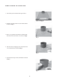
HI DELTA OUTDOOR VENT INSTRUCTIONS
1. Turn off the power and shut off the gas to heater.
Heater as shipped
2. Slide the vent collar from kit over the collar on heater
as shown in Fig. 1.
3. Drill a 3/16” pilot hole into the heater collar through
each of the holes on the lower vent collar. See Fig. 1.
Fig. 1
4. Take four of the self-tapping screws from the kit and
screw into the holes as shown in Fig. 2.
.
Fig. 2
5. Slide tinnerman clips over the small bracket as shown
in Fig. 3.
Fig. 3
38
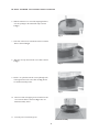
HI DELTA OUTDOOR VENT INSTRUCTIONS CONTINUED
6. Slide the collector over vent collar, aligning the holes
over the openings in the tinnerman clips as shown
in Fig. 4.
Fig. 4
7. Take four of the screws from the kit and screw into the
holes as shown in Fig. 4.
8. Slide the vent cap down into the vent collar as shown
in Fig. 5.
Fig. 5
9. Drill a 3/16” pilot hole into the vent cap through each
of the upper holes in the vent collar. See Fig. 6. Also
see finished assembly below.
Fig. 6
10. Take four of the self tapping screws from the kit and
screw into the holes as shown in Fig. 6. Also see
finished assembly below.
11. Turn the power on and turn gas on.
Finished assembly
39
HI DELTA FILTER BOX KIT
NOTICE:
These instructions are intended for use by qualified personnel specifically trained and experienced
in the installation of this type of heating equipment and related system components. Installation and
service personnel are required to be licensed in some states. Persons not qualified shall not attempt
repairs according to these instructions.
Vent collar
Air intake collar
THIS KIT INCLUDES:
1- Filter box
1- Decal (attached)
6- Screws
1- Instructions
MODEL
992-1532
1802-2342
PART NUMBER
#007101- 8”
#007102- 10”
Heater as shipped
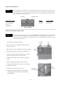
HI DELTA FILTER BOX INSTRUCTIONS
NOTICE:
These instructions pertain only to units installed outdoors only. All Hi Delta units are shipped with the
air intake collar mounted temporarily on the top of the heater for shipping purposes. If this is to be
installed outdoors, the air intake collar and filter box must be relocated to the back of the unit to prevent
recirculation of flue products.
1. Turn off the gas and power to the unit.
Air intake
collar
Vent
collar
2. Remove the four screws holding the air intake collar on
the top of the unit.
3. Remove the four screws holding the cover plate. See Fig. 1.
Cover
plate
4. Remove the white gasket paper off the air intake collar.
5. Align the four holes of the air intake collar over the four
holes on the opening on the back of the heater.
6. Mount air intake collar on back of the heater using four
screws.
Fig. 1 Back of heater
7. Remove the white gasket paper off the cover plate.
8. Align the four holes of the cover plate over the opening
on the top of the heater.
9. Mount the cover plate using four screws.
Filter
warning
Align filter
box to edges
10. Hold the box over the air intake filter warning decal
facing outward and align the top and side edges as
shown in Fig. 2.
Fig. 2
40
Back of heater
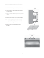
HI DELTA FILTER BOX INSTRUCTIONS CONTINUED
11. Mark the four holes through filter box for screw locations.
Air intake
collar
12. Using a 1/16 drill bit, drill a pilot hole in each of the holes
previously marked.
13. Mount the filter box to the unit using four screws provided
in the kit.
14. Install filter under filter box on top of air intake. See Fig. 3.
NOTE: The filter media fits loosely in the filter box. When
the fans energize, the filter is drawn onto the top
of the collar and is held in place by the suction.
The checked side of filter sits on air intake collar.
Side view
15. Install two screws in the holes behind cover plate.
See Fig. 4.
Fig. 3
Filter
Install screws here
Fig. 4
41
SECTION K: CONTROLS
WARNING:
Installation, adjustment and service of boiler controls including timing of various operating
functions must be performed by a qualified installer, service agency or the gas supplier. Failure to
do so may result in control damage, boiler malfunction, property damage, personal injury, or death.
WARNING:
Turn off the power to the boiler before installation, adjustment or service of the Central Point Wiring
board or any boiler controls. Failure to do so may result in board damage, boiler malfunction,
property damage, personal injury, or death.
CAUTION:
This appliance has provisions to be connected to more than one (1) supply source. To reduce the risk
of electric shock, disconnect all such connections before servicing.
CAUTION:
Risk of electric shock. More than one (1) disconnect switch may be required to de-energize the
equipment before servicing.
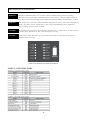
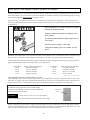
VIEW OF EXTERNAL LED INDICATOR DECAL
TABLE L-1 LED INDICATORS
42
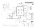
Boiler Sequence of Operations
HI-DELTA Model 992
The black (hot) wire leads you directly to the Main Power Switch. This switch is located at the bottom right-front corner of
the control compartment. When the main power switch is placed in the “ON” position, both the 120 v and 24 v terminal blocks
on the Main Circuit Board will be powered. Also the power light will turn on. The following 24 v safety components are
immediately energized: Low Water Cut-off, Blocked Vent Switch, Manual Reset Limit Control, Low Gas Pressure Switch and
the High Gas Pressure Switch (optional). At this point if all the preceding safety switches are closed, then Relay No. 1 (n.c.)
will be energized and the safety light will turn off.
When the Auto On- Off switch is turned ON, the boiler is now ready for a call for heat.
When STAGE 1 calls for heat, the CALL FOR HEAT LIGHT will come on. The Economaster Board will have power and the
pump will turn on. If the pump generates enough flow to activate the flow switch, turn on the flow light, then power will be
applied to the thermostat terminal of the Ignition Module No. 1 and Blower No. 1 will activate. Air Pressure Switch No. 1 would
then close. The pressure switch terminal on the Ignition Module will be energized also. The Unit will now undergo a 15
second pre-purge. After the pre-purge cycle, Hot Surface Igniter will heat up. The heat-up period takes about 30 seconds after
which a trial for ignition is initiated. During the trial for ignition, which lasts for four seconds, power is applied to Firing Valve
No. 1. If within the four seconds, the Remote Sensor establishes flame rectification, then Firing Valve No. 1 stays open and
the Stage 1 light will turn on. Power from the Valve terminal will power Relay K3. Power will also be applied to Relay K2 thereby
turning Blower No. 2 on.
When Stage 2 calls for heat, power will pass through Time Delay Relay No. 1, then after 10 seconds to Air Pressure Switch
No.2, then through Relay K3, and then Firing Valve No. 2. At the same time, Stage 3 would be ready to fire. The Stage 2 light
will come on also, at this time.
When Stage 3 calls for heat, power is applied to Firing Valve No. 3(Solenoid gas valve located on the lower manifold of Firing
Valve No.2). The Stage 3 light will also come on, at this time.
43
HI-DELTA Models 1262
The black (hot) wire leads you directly to the Main Power Switch. This switch is located at the bottom right-front corner
of the control compartment. When the main power switch is placed in the “ON” position, both the 120 v and 24 v terminal
blocks on the Main Circuit Board will be powered. Also the power light will turn on. The following 24 v safety components are immediately energized: Low Water Cut-off, Blocked Vent Switch, Manual Reset Limit Control, Low Gas Pressure
Switch and the High Gas Pressure Switch (optional). At this point if all the preceding safety switches are closed, then
Relay No. 1 (n.c.) will be energized and the safety light will turn off.
When the Auto On- Off switch is turned ON, the boiler is now ready for a call for heat.
When STAGE 1 calls for heat, the CALL FOR HEAT LIGHT will come on. The Economaster Board will have power and the
pump will turn on. If the pump generates enough flow to activate the flow switch, turn on the flow light, then power will
be applied to the thermostat terminal of the Ignition Module No. 1 and Blower No. 1 will activate. Air Pressure Switch No.
1 would then close. The pressure switch terminal on the Ignition Module No. 1 will be energized also. The Unit will now
undergo a 15 second pre-purge. After the pre-purge cycle, Hot Surface Igniter No. 1 will heat up. The heat-up period takes
about 30 seconds after which a trial for ignition is initiated. During the trial for ignition, which lasts for four seconds,
power is applied to Firing Valve No. 1. If within the four seconds, the Remote Sensor No. 1 establishes flame rectification,
then Firing Valve No. 1 stays open and the Stage 1 light will turn on. Power from the Valve terminal will energize Relay K3
and also be applied to a contact on Relay K4.
When Stage 2 calls for heat, power will be applied to Air Pressure Switch No.2 and Relay K2 energizing Blower No. 2.
When Air Pressure Switch No. 2 closes, power will pass to the normally closed contact of Relay K3, then through a closed
contact on Relay K4, then through Time Delay Relay No.2, and then Firing Valve No. 2. Power will also pass through Time
Delay Relay No. 1 and after 10 seconds Stage 3 would be ready to fire. The Stage 2 light will come on also, at this time.
When Stage 3 calls for heat, power is applied to Relay K3, opening the normally closed contacts thereby removing power
from Firing Valve No. 2. Power also goes through Time Delay Relay No.3, after 10 seconds Firing Valve No. 3 turns on.
When stage 4 calls for heat, power will go through contacts on Relay K4. If Relay K4 is activated, then power is applied to
Firing Valve No. 4.
44
HI-DELTA Models 1532-1802
The black (hot) wire leads you directly to the Main Power Switch. This switch is located at the bottom right-front corner of
the control compartment. When the main power switch is placed in the “ON” position, both the 120 v and 24 v terminal blocks
on the Main Circuit Board will be powered. Also the power light will come on. The following 24 v safety components are
immediately energized: Low Water Cut-off, Blocked Vent Switch, Manual Reset Limit Control, Low Gas Pressure Switch and
the High Gas Pressure Switch (optional). At this point if all the preceding safety switches are closed, then Relay No. 1 (n.c.)
will be energized and the safety light will turn off.
When the Auto On- Off switch is turned On, the boiler is now ready for a call for heat.
When STAGE 1 calls for heat, the CALL FOR HEAT LIGHT will come on. The Economaster Board will have power and the
pump will turn on. If the pump generates enough flow to activate the flow switch, turn on the flow light, then power will be
applied to the thermostat terminal of the Ignition Module No. 1 and Blower No. 1 will activate. Air Pressure Switch No. 1 would
then close. The pressure switch terminal on the Ignition Module No. 1 will be energized also. The Unit will now undergo a 15
second pre-purge. After the pre-purge cycle, Hot Surface Igniter No. 1 will heat up. The heat-up period takes about 30
seconds after which a trial for ignition is initiated. During the trial for ignition, which lasts for four seconds, power is applied
to Firing Valve No. 1. If within the four seconds, the Remote Sensor No. 1 establishes flame rectification, then Firing Valve No.
1 stays open and the Stage 1 light will turn on. Power from the Valve terminal will also power Time Delay Relay No. 2. After 10
seconds power will be applied to Relay K3, closing contacts to power Relay K2 thereby turning Blower No. 2 on.
When Stage 2 calls for heat, power will pass through Air Pressure Switch No.2, through a normally closed contact of Relay
K5, then through Relay K3, and then Firing Valve No. 2. The Stage 2 light will come on also, at this time.
When Stage 3 calls for heat, the Thermostat terminal on Ignition Module No. 2 is energized. Ignition Module No. 2 commences its pre-purge cycle (15 seconds). After the pre-purge cycle, Hot Surface Igniter No. 2 will heat up. The heat-up period
takes about 30 seconds after which a trial for ignition is initiated. During the trial for ignition, which lasts for four seconds,
power from Valve Terminal is applied to Relay K4 and Firing Valve No.3. If within four seconds, the Remote Sensor No. 2
establishes flame rectification, then Firing Valve No. 3 stays open and Stage 3 light will turn on. At this time power is also
applied to Time Delay Relay No. 1, preparing for a call for heat on Stage 4.
When stage 4 calls for heat, power will go through contacts on Relay K4. If Relay K4 is activated, (a verification that flame
rectification has been established on Firing Valve No.3), then power is applied to Firing Valve No. 4. If no flame rectification
is verified then Firing Valve No. 4 will not be powered.
45
HI-DELTA Models 2002-2342
All Hi- Delta boilers are wired similarly up to and including the safeties. After which gas valve, burner, blower and ignition
module quantities vary according to the BTU input. The staging logic sometimes requires timers and relays for complete and
safe operation.
The black (hot) wire leads you directly to the Main Power Switch. This switch is located at the bottom right-front corner of
the control compartment. When the main power switch is placed in the “ON” position, both the 120 v and 24 v terminal blocks
on the Main Circuit Board will be powered. Also the power light will come on. The following 24 v safety components are
immediately energized: Low Water Cut-off, Blocked Vent Switch, Manual Reset Limit Control, Low Gas Pressure Switch and
the High Gas Pressure Switch (optional). At this point if all the preceding safety switches are closed, then Relay No. 1 (n.c.)
will be energized and the safety light will turn off.
When the Auto On- Off switch is turned On, the boiler is now ready for a call for heat.
When STAGE 1 calls for heat, the CALL FOR HEAT LIGHT will come on. The Economaster Board will have power and the
pump will turn on. If the pump generates enough flow to activate the flow switch, turn on the flow light, then power will be
applied to the thermostat terminal of the Ignition Module No. 1 and Blower No. 1 will activate. Air Pressure Switch No. 1 would
then close supply power to relays K2 and K4, thus energizing Blowers No. 2 and No. 3. The pressure switch terminal on the
Ignition Module No. 1 will be energized also. The Unit will now undergo a 15 second pre-purge. After the pre-purge cycle, Hot
Surface Igniter No. 1 will heat up. The heat-up period takes about 30 seconds after which a trial for ignition is initiated. During
the trial for ignition, which lasts for four seconds, power is applied to Firing Valve No. 1. If within the four seconds, the
Remote Sensor No. 1 establishes flame rectification, then Firing Valve No. 1 stays open and the Stage 1 light will turn on.
Power from the Valve terminal will also verify the closure of Pressure Switch No. 2. Power will then pass through Time Delay
Relay No. 2, ten seconds later Relay K3 is activated, opening Firing Valve No. 1A and powering Relay K7.
When Stage 2 calls for heat, power will pass through a normally closed contact of Relay K6, then through Time Delay Relay
No.3, ten seconds later, through Relay K7 and then Firing Valve No. 2. The Stage 2 light will come on also, at this time.
46
When Stage 3 calls for heat, the Thermostat terminal on Ignition Module No. 2 is energized. Ignition Module No. 2 commences its pre-purge cycle (15 seconds). After the pre-purge cycle, Hot Surface Igniter No. 2 will heat up. The heat-up period
takes about 30 seconds after which a trial for ignition is initiated. During the trial for ignition, which lasts for four seconds,
power from Valve Terminal is applied to Relay K5 and Firing Valve No.3. If within four seconds, the Remote Sensor No. 2
establishes flame rectification, then Firing Valve No. 3 stays open and Stage 3 light will turn on. At this time power is also
applied to Time Delay Relay No. 1, preparing for a call for heat on Stage 4.
When stage 4 calls for heat, power will go through contacts on Relay K5. If Relay K5 is activated, (a verification that flame
rectification has been established on Firing Valve No.3), then power is applied to Firing Valve No. 4. If no flame rectification
is verified then Firing Valve No. 4 will not be powered.
47
IGNITION CONTROL MODULE
The interrupted proved ignition device conserves energy. When additional heat is
needed, the combustion air blower starts to purge all air from the combustion
chamber for about 15 seconds. On proof of air flow, the air proving switch closes
and the igniter is energized, eliminating the fuel costs of maintaining a constant
pilot. To assure safe operation, the gas valve cannot open until the pilot igniter is
verified. The 100% igniter safety is an electronic device which closes the main
gas valve within 8/10 of a second whenever the flame is interrupted. Main burner
is automatically lit when the device is powered and pre-purged. Unit performs its
own safety check and opens the main valve only after the igniter is proven to be
capable of ignition.
Fig. #9235
IGNITION MODULE
HIGH LIMIT (MANUAL RESET)
The boiler is equipped with a manual reset high limit temperature device. Push
the reset button and adjust the setting to 30° F or 40° F above desired operating
temperature.
Drw. #8644
Fig. J-3
MANUALRESETHIGHLIMIT
FLOW SWITCH
Dual-purpose control shuts off boiler in case of pump failure or low water flow.
Mounted and wired in series with the main gas valve. Check with Manufacturer for
proper paddle size. Utilize correct paddle size for proper operation.
NOTICE:
Flow switch will not operate if flow is less than 20 GPM.
Drw. #8241
Fig. J-4
FLOW SWITCH
OPERATING CONTROL
The heater may be equipped with different types of operating controls. Consult
data sheet supplied with installation instructions. See Section L for adjustment
safety precautions on domestic hot water applications.
Drw. #8643
THERMOSTAT CONTROL
48
LOW WATER CUT OFF (OPTIONAL)
The low water cut off automatically shuts down the burner whenever
water level drops below the level of the sensing probe. A 3 second
time delay prevents premature lockout due to temporary conditions
such as power fluctuations or air pockets.
Drw. #8996
Fig.# J-5
LOW WATER CUTOFF
HIGH AND LOW GAS PRESSURE SWITCHES
The low gas pressure switch mounts upstream of the gas valve to ensure
that sufficient gas pressure is present for proper regulator performance.
The low gas pressure switch automatically shuts down the boiler if gas
supply drops below the factory setting of 5" W.C. for Natural gas, and
10" W.C. for Propane gas.
The high gas pressure switch (optional) mounts down-stream of the gas
valve. If the gas pressure regulator fails, the high gas pressure switch
automatically shuts down the burner.
Drw. #8236
Fig.# J-6
GAS PRESSURE SWITCH
49
WIRE DIAGRAM MODEL 992
Reference Drawing Number M152471
Rev L
H8/W8
50
WIRE DIAGRAM MODEL 1262
Reference Drawing Number M152467
Rev T
H9/W9
51
WIRE DIAGRAM MODEL 1532-1802
Reference Drawing Number M152468
Rev R
H9/W9
52
WIRE DIAGRAM MODEL 2002-2342
Reference Drawing Number M152469
Rev R
H9/W9
53
SECTION L: GENERAL SAFETY PRECAUTIONS
To meet commercial water use needs, the temperature Hi-Limt on this hot water boiler is adjustable up to 210°F. However,
water temperatures over 125°F can cause severe burns instantly or death from scalds. The preferred starting point for setting
the control for supplying general purpose hot water is 125°F.
Safety and energy conservation are factors to be considered when setting the water temperature on the thermostat. The
most energy efficient operation will result when the temperature setting is the lowest that satisfies the needs consistent with
the application.
Water temperature over 125°F can cause severe burns
instantly or death from scalds.
Children, disabled and elderly are at highest risk of
being scalded.
See instruction manual before setting temperature at
water heater.
Feel water before bathing or showering.
Temperature limiting valves are available, see note
below.
Maximum water temperatures occur just after the boiler’s burner has shut off. To determine the water temperature being
delivered, turn on a hot water faucet and place a thermometer in the hot water stream and read the thermometer.
The following chart details the relationship of water temperature and time with regard to scald injury and may be used as a
guide in determining the safest water temperature for your applications.
Temperature
120°F.
125°F.
130°F.
135°F.
Time to Produce Serious Burn
More than 5 minutes
1-1/2 to 2 minutes
About 30 seconds
About 10 seconds
Temperature
140°F.
145°F.
150°F.
155°F.
Time to Produce Serious Burn
Less than 5 seconds
Less than 3 seconds
About 1-1/2 seconds
About 1 second
Table courtesy of The Shriners Burn Institute
TIME/TEMPERATURE RELATIONSHIPS IN SCALDS
The temperature of the water in the hot water boiler can be regulated by setting the temperature dial on front of the
thermostat. To comply with safety regulations the thermostat was set at its lowest setting before the hot water boiler was
shipped from the factory. The illustration below shows the thermostat and how to adjust the water temperature.
To adjust the water temperature, insert a small straight
screwdriver into slotted screw in hole in front of thermostat
and turn wheel to desired setting.
CAUTION!!
Adjustment
Screw
- Hotter water Increases the risk of SCALDING!
There is a Hot Water SCALD Potential if the thermostat is set too high.
NOTE: When this hot water boiler is supplying general purpose hot water requirements for use by individuals, a thermostatically controlled mixing valve for reducing point of use water temperature is recommended to reduce the risk of scald
injury. Contact a licensed plumber or the local plumbing authority for further information.
54
SECTION M: PRE-START-UP
FILLING SYSTEM-HEATING BOILERS
Fill system with water. Purge all air from the system using purge valve sequence. After system is purged of air, lower system
pressure. Open valves for normal system operation, fill system through feed pressure. Manually open air vent on the
compression tank until water appears, then close vent.
DOMESTIC HOTWATER BOILERS
Purge all air from system before lighting boiler. This can be normally be accomplished by opening a downstream valve.
INSPECT VENTING SYSTEM:
1.
2.
Check all vent pipe connections and flue pipe material.
Ensure vent terminations are installed per code and are clear of all debris or blockage.
FOR YOUR SAFETY READ BEFORE LIGHTING
WARNING:
1.
2.
3.
4.
5.
6.
If you do not follow these instructions exactly, a fire or explosion may result causing property damage,
personal injury or loss of life.
This appliance does have an intermittant pilot. It is equipped with an ignition device which automatically lights the
pilot. Do Not try to light the pilot or burner by hand.
BEFORE OPERATING, smell all around the appliance area for gas. Be sure to smell next to the floor because some
gas is heavier than air and will settle on the floor.
WHAT TO DO IF YOU SMELL GAS
• Do not try to light any appliance.
• Do not touch any electrical switch; do not use any telephone in your building.
• Immediately call your gas supplier from a neighbor's telephone. Follow the gas supplier's instructions.
• If you cannot reach your gas supplier, call the fire department.
Use only your hand to push in or turn the gas control knob. Never use tools. If the knob will not turn by hand, do
not try to repair it, call a qualified service technician. Forced or attempted repair may result in a fire or explosion.
Do not use this appliance if any part has been under water, immediately call a qualified service technician to inspect
the appliance and to replace any part of the control system and any gas control which has been under water.
Check around unit for debris and remove combustible products, i.e. gasoline, etc.
PRE-START-UP CHECK
1.
2.
3.
4.
Verify boiler is filled with water.
Check system piping for leaks. If found, repair immediately.
Vent air from system. Air in system can interfere with water circulation.
Purge air from gas line up to boiler.
55
SECTION N: HI-DELTA INITIAL START-UP
1.0
•
•
•
•
•
•
•
•
TOOLS NEEDED
One 12-0-12, 24” scale manometer
6-0-6, 12” scale manometers* with tees
7/16” open end wrench
1/2” open end wrench
Screwdriver
Volt meter
3/16” Allen wrench
Jumper cable
* See table for manometer quantities.
2.0
PREPARATION FOR START-UP
WARNING:
2.1
DO NOT TURN ON GAS AT THIS TIME
Check Power Supply
With volt meter at incoming power check voltage between:
Hot - Common
(≈120 VAC)
Hot - Ground
(≈120 VAC)
Common - Ground
(< 1 VAC)
If Common - Ground is > 1 VAC - STOP: Contact electrician to correct ground failure. Warning: Failure to do this may
burn out 120V-24V transformer, or may cause other safety control damage or failure.
2.2 Attach Manometers to Measure Pressures
•
•
•
Attach 24" scale manometer to the first main gas shut-off valve pressure tapping.
Attach one 12" scale manometer to the outlet side of the second main gas shut-off valve pressure tapping.
Attach one 12" scale manometer to — Pull rubber tube from air pressure switch off the aluminum tubing and
connect the manometer using a tee.
Turn Off Main Gas Valve;
2.3 Check the Gas Supply Pressure
1.
2.
3.
4.
Slowly turn on main gas shut-off valve;
Read the gas supply pressure from the manometer; minimum supply pressure for natural gas is 5” W.C.,
recommended supply pressure is 7” W.C.. Minimum supply pressure for propane is 11” W.C..
If pressure is > 14" W.C.; Turn off the valve;
Check if the service regulator is installed and/or adjust the service regulator.
56
3.0 START-UP
3.1 Blower Adjustment
1.
2.
3.
4.
5.
6.
Disconnect all fan pressure switch tubings at plenum and connect manometer using a tee.
Close all manual firing valves.
Turn power on;
Check manometers attached to fan pressure switches. The readings should be 1.4 + .2"W.C. If not, adjust the air shutter
on the blowers to attain the correct value.
Turn power off.
Reconnect all fan pressure switch tubing to original positions.
3.2 Main Burner Adjustment
1.
2.
3.
4.
5.
6.
Turn off unit.
Open manual firing valve(s).
Turn on the unit, wait 15 seconds, and the igniter should glow. Sight glass to check ignitor at both ends of the boiler.
Gas valves should be open after 45 seconds.
If burner does not light on first trial. It will retry, up to 3 times
Main burner ignition – check manifold gas pressure at gas valve outlet pressure tap. This should read 3.4 + .1"W.C.
for natural gas and 10.5” W.C. for propane.
If the pressure reading differs by more than + .1"W.C. Remove screw cover off the gas pressure regulator, adjust
main burner manifold pressure. Replace the screw cover of the gas regulator. Repeat step 2 – 5 on other valves as
necessary.
Your Hi-Delta is tuned in!
3.4 Safety Inspection
•
•
•
•
Replace main gas manifold adjustment cap.
Check all thermostats and high limit settings.
During the following safety checks leave manometers hooked up, check and record.
If other gas fired equipment are in the room and on same gas main check all pressures on the Hi-Delta with all other
equipment running.
Remember, incoming gas pressure could be lower than the stated W.C., provided 3.2.5 is met.
•
•
•
•
•
•
Check thermostats for ON/OFF operation.
Check Hi Limits for ON/OFF operation.
While in operation, check flow switch operation
Check the low gas pressure switches (For proper adjustment, if available, use the attached manometers to set pressure.
The scales on the switch are approximately only ); Low gas pressure switch must be set at 5" W.C. for natural gas and
10.5” W.C. for propane.
High gas pressure switch (optional) at 1" W.C. above manifold pressure.
Insert ignition control lockout tests as safety check.
3.5 Follow-Up
•
•
Safety checks must be recorded as performed.
Turn unit on.
After main burner ignition.
•
•
•
•
•
Check Manometer for proper reading.
Cycle unit several times and recheck readings
Reanalyze with unit running record or print results.
Remove all Manometers and replace hose, remove jumper, replace all gas pressure caps.
Check for gas leaks one more time.
57
PILOT TURN DOWN TEST FOR RAYPAK HI DELTA BOILERS
Paragraph CM-130 (e)(1) specifies that a pilot turn down test be conducted annually. Please see below explanation and
directions for how to do this.
The Hi Delta boilers, depending on their size, have from two to five burner sections. Each burner section is supplied gas
by dual gas valves incorporated in single valve body. A maximum of three burner sections may be controlled by a single
hot surface ignition system. The middle of the three burner sections is lighted directly with a hot surface ignition system.
The burner section that is ignited directly by the hot surface ignition system serves as a supervised pilot to light the
burner sections on either side of it. The burner sections on either side of the supervised section (pilot) are electrically
interlocked with the supervised ignition system so as to not be energized unless flame is proven on the center section
which is acting as a pilot to light the right and left hand sections.
The pilot turn down test is conducted as follows:
1)
2)
Turn off manual valves on non-supervised burner sections.
Turn on electrical power and adjust thermostat to call for heat.
3)
Wait for completion of ignition sequence to light burner section being utilized as a pilot for those turned off in (1)
above.
4)
Gradually reduce manifold pressure (flame) on supervised burner section by closing manual gas valve. Watch
for shut down due to loss of supervised flame signal as pressure is being reduced. Flame signal should be lost
before manifold pressure goes below 2 inches water column.
LEAK TEST PROCEDURE: DUAL-SEAT GAS VALVES
Proper leak testing requires three pressure test points in the gas train.
Test point A is upstream of the automatic gas valve. On the first automatic valve, this is a bleedle valve. On the
other valves, this is a plugged port. The bleedle valve on the first valve may be used for all the other valves as
well.
Test point B is a bleedle valve located between the two automatic gas valve seats.
Test point C is located downstream of both automatic gas valve seats and upstream of the manual valve. On the
manual valve, this is a bleedle valve. Identical readings will be found at the plugged port labeled as Alternate C”.
Refer to attached diagrams. Numbers on the diagram refer to the steps below:
These tests are to be conducted with the electrical power to the boiler turned off.
1)
Manually close the downstream leak test valve.
2)
Open test point A and connect a manometer to it. Verify that there is gas pressure and that it is within the proper
range (note: must not exceed 14 inches water column).
3)
Open test point B and connect a rubber tube to it. Connect the other end of the tube to a manometer and look for a
build u of pressure. Increasing pressure indicates a leaking gas valve.
58
4)
Next, close the upstream manual gas valve and remove the manometers from test point A and from test point B.
Connect a rubber tube from test point A to test point B and open the upstream manual gas valve. Make sure that test
points A & B have been opened so as to allow gas to flow. This will bring pressure to the second valve seat.
5)
Open test point C and connect a second rubber tube to it. Connect the other end of the tube to a manometer and
look for a build up of pressure. Increasing pressure indicates a leaking gas valve.
6)
Remove rubber test tube and manometers. Close each test point valve as the tubes are removed.
7)
Connect a manometer to each test point (one at a time) and look for a build up of pressure. If a build up of pressure is
detected, check each test point valve to see if it is tightly closed. If leak persists, replace test point valve(s).
8)
After no leakage has been verified at all valve seats and test valves, open downstream leak tests valve and restore
electrical power to boiler.
This completes leak testing for a single Hi Delta manifold riser. Repeat steps 1-8 for each riser.
59
SECTION O: POST START-UP CHECK
Check off steps as completed:
1.
2.
3.
4.
5.
6.
7.
8.
9.
10.
11.
12.
13.
14.
15.
Boiler and heat distribution units or storage tank filled with water?
Automatic air vent, if used, open two full turns during venting procedure?
Air purged from system?
Air purged from gas piping? Piping checked for leaks?
Followed start-up procedure for proper start-up?
Is burner flame visible?
Test safety controls: If boiler is equipped with a low water cutoff or additional safety controls, test for operation as
outlined by manufacturer. Burner should be operating and should go off when controls are tested. When safety devices
are restored, burners should reignite after pre-purge time delay.
Test limit control: While burner is operating, move indicator on high limit control below actual boiler water
temperature. Burner should go off while blower and circulator continue to operate. Raise setting on limit control above
boiler water temperature and burner should reignite after pre-purge time delay.
Test ignition system safety device:
·
Turn on manual gas valve. Turn power on.
·
Set thermostat to call for heat.
·
When the unit is in operation. Disconnect combustion air blower pressure switch, burner should go off
immediately.
·
Wait 5 minutes.
·
Reconnect combustion air pressure switch, burner should reignite after pre-purge time delay.
To restart system, follow lighting instructions in Section O.
High limit control set to design temperature requirements of system?
For multiple zones: flow adjusted as required in each zone?
Boiler cycled with thermostat? Raise to highest setting and verify boiler goes through normal start-up cycle.
Reduce to lowest setting and verify boiler goes off.
Observed several operating cycles for proper operation?
Set room thermostat or tankstat to desired temperature?
Reviewed all instructions shipped with this boiler with owner or maintenance person, returned to envelope
and given to owner or placed in pocket inside front panel on boiler?
60
SECTION P: OPERATION
OPERATING INSTRUCTIONS
Lighting Instructions
1.
2.
3.
4.
STOP! Read the safety information first.
Set the thermostat to the lowest setting.
Turn off all electric power to the appliance.
This appliance is equipped with an ignition device which automatically lights the burner. Do Not try to light the
burner by hand.
5. Remove upper front panel.
6. Turn on main manual gas valve.
7. Wait five (5) minutes to clear out any gas. Then smell for gas, especially near the floor. If you then smell gas. STOP!
Follow the steps in the safety information on the front cover.
If you do not smell gas, go to next step.
8. Turn on all electric power to the appliance.
9. Set thermostat to desired setting. The appliance will operate. The igniter will glow after the pre-purge time delay (15
seconds). After igniter reaches temperature (45 seconds) the main valve will open. System will try for ignition three (3)
times. If ignition is not sensed, lockout will commence.
10. If the appliance will not operate, follow the instruction "To Turn Off Gas To Appliance", and call your service
technician or gas supplier.
11. Replace access panel.
TO TURN OFF GAS TO APPLIANCE
1.
2.
3.
4.
5.
Set the thermostat to lowest setting.
Turn off all electric power to the appliance if service is to be performed.
Remove upper front panel.
Turn off main manual gas valve.
Replace access panel.
If boiler fails to start, check for:
•
•
•
•
•
Loose connections, blown fuse or service switch off?
High temperature limit switch set below boiler water temperature?
Thermostat set below room temperature?
Gas not turned on at meter or boiler.
Incoming gas pressure less than 5" W.C. for Natural gas, 11" W.C. for Propane.
61
SECTION Q: MAINTENANCE
SUGGESTED MINIMUM MAINTENANCE SCHEDULE:
Regular service by a qualified service agency and maintenance must be performed to assure maximum boiler operating
efficiency.
Maintenance as outlined below may be performed by the owner.
Yearly (Beginning of each heating season):
1.
2.
3.
4.
5.
6.
7.
Annual service call by qualified service agency.
Visually check top of vent for soot. Call service person to clean. Some sediment at bottom of vent is normal.
Visually inspect venting system for proper function, deterioration or leakage.
Check that boiler area is free from combustible materials, gasoline, and other flammable vapors and liquids.
Check for and remove any obstruction to the flow of combustion or ventilation air to boiler.
Follow pre-start-up check in Section N.
Visually inspect burner flame. Should see light blue flame. Visually inspect hot surface ignitor for damage, cracking
or debris build-up.
8. Check operation of safety devices. Refer to manufacturer’s instructions.
9. Follow oil-lubricating instructions on circulator. Over-oiling will damage circulator. Water-lubricated
circulators do not need oiling.
10. To avoid potential of severe burn, DO NOT REST HANDS ON OR GRASP PIPES. Use a light touch - return
piping will heat up quickly.
11. Check blower and blower motor. Clean and oil as necessary.
12. Check for piping leaks around circulators, relief valves and other fittings. Repair, if found. DO NOT use petroleum
based stop leak.
Daily:
1.
2.
Check that boiler area is free from combustible materials, gasoline, and other flammable vapors and liquids.
Check for and remove any obstruction to the flow of combustion or ventilation air to boiler.
Monthly:
1.
2.
3.
4.
Check for piping leaks around circulators, mixing valves, relief valves, and other fittings.
If found, repair at once. DO NOT use petroleum-based stop leak compounds.
Visually inspect burner flame.
Visually inspect venting system for proper function, deterioration or leakage.
Check air vents for leakage.
Quarterly:
1.
2.
3.
Check relief valve. Refer to manufacturer’s instructions on valve.
Test low water cutoff, if used. Refer to manufacturer’s instructions.
Clean screen and air filter in intake.
62
PREVENTIVE MAINTENANCE SCHEDULE
Required procedure in CSD-1 States and good practice for all Hi-Delta installations.
Daily
1.
2.
3.
Check gages, monitors and indicators. (See page 6 of the Operating and Installation Instructions Manual).
Check instrument and equipment settings. (See page 47 of the Operating and Installation Instructions Manual).
Check burner flame. (Should see light blue flame).
Weekly
1.
2.
3.
4.
5.
6.
For low-pressure boilers, test low-water fuel cutoff device. (With at least one stage of the appliance on, depress the
low water cut-off test button, appliance should shut-off and ignition fault light should come on. Depress reset
button to reset).
Check igniter. (Resistance reading should be 30- 70 ohms).
Check flame signal strength. (Flame signal should be greater than 1 microamp).
Check flame failure detection system. (See attached Turn Down Test Procedure).
Check firing rate control. (Check manifold pressure, see page 47 of the Operating and Installation Instructions
Manual).
Make aural and visual check of pilot and main fuel valves.
Monthly
1.
2.
3.
Check flue, vent, stack, or outlet dampers.
Test fan air pressure. (See page 47 of the Operating and Installation Instructions Manual).
Test high and low gas pressure interlocks. (See page 47 of the Operating and Installation Instructions Manual).
Semi-Annually
1.
2.
3.
4.
5.
Recalibrate all indicating and recording gages.
Check flame failure detection system components. (See attached Turn Down Test Procedure).
Check firing rate control. (Check manifold pressure, see page 47 of the Operating and Installation Instructions
Manual).
Check piping and wiring of all interlocks and shutoff valves.
Inspect burner components.
Annually
1.
2.
3.
4.
5.
6.
7.
8.
Flame failure detection system, pilot turndown test. (See attached Turn Down Test Procedure).
Test high limit and operating temperature. (See page 48 of the Operating and Installation Instructions Manual).
Check flame sensors, (Flame signal should be greater than 1 microamp).
Conduct a combustion test. (Carbon Dioxide 7-9 %; Carbon monoxide < 200 ppm).
Check all coils and diaphragms; test other operating parts of all safety shutoff and control valves. Coils- check for
60 cycle hum or buzz; diaphragms- using soapy water solution check for leaks on the vent outlets and all fittings on
the valves; on other safety devices increase or decrease settings (depending on the type of control) until the safety
circuit opens. Reset to original setting after each device is tested.
Perform leakage test on pilot and main gas valves. (See attached Leak Test Procedure).
Test purge air switch in accordance with manufacturer’s instructions. (Turn panel switch to the on position until
blower is proven, then turn the switch to off. Blower should stay on for approximately 30 seconds).
Test burner position interlock in accordance with manufacturer’s instructions. (Remove front panel and visually
check burner orientation, all three screws holding the burner must be in place and flat portion of the flange must be
on top in the horizontal position).
As Required
1.
2.
3.
4.
Recondition or replace low water fuel cutoff device.
For gas fired burners, check drip leg and gas strainers.
Flame failure detection system, pilot turndown test. (See attached Turn Down Test Procedure).
Test safety/safety relief valves in accordance with ASME Boiler and Pressure Vessel Code Sections VI and VII.
63
APPENDIX A
INSIDE COMBUSTION AIR CONTAMINATION:
All boilers experience some condensation during start-up.
The condensate from flue gas is slightly acidic. In most cases the pH level is not harmful to vents or drains. When
combustion air is contaminated by vapors from products in areas listed below, the acidic levels in the condensate increase.
Higher acidic levels attack many materials, including stainless steel commonly used in high efficiency systems.
The boiler can use special corrosion-resistant nonmetallic intake vent material. You may, however, choose to use outside
combustion air for one or more of these reasons:
• installation is in an area containing contaminants listed below which will induce acidic condensation.
• you want to reduce infiltration into your building through openings around windows and doors.
• you are using AL29-4C stainless steel vent pipe, which is more corrosion-resistant than standard metallic vent
pipe. In extremely contaminated area, this may also experience deterioration.
Products causing contaminated combustion air:
• spray cans containing chloro/fluorocarbons
• permanent wave solutions
• chlorinated waxes/cleaners
• chlorine-based swimming pool chemicals
• calcium chloride used for thawing
• sodium chloride used for water softening
• refrigerant leaks
• paint or varnish removers
• hydrochloric acid/muriatic acid
• cements and glues
• antistatic fabric softeners used in clothes dryers
• chloride-type bleaches, detergents, and cleaning solvents found in household laundry rooms
• adhesives used to fasten building products
• ... and other similar products.
Areas causing contaminated combustion air:
• dry cleaning/laundry areas and establishments
• metal fabrication plants
• beauty shops
• refrigeration repair shops
• photo processing plants
• auto body shops
• plastic manufacturing plants
• furniture refinishing areas and establishments
• new building construction
• remodeling areas.
Check for areas and products as listed above before installing boiler. If found:
• remove products permanently, OR
• provide outdoor combustion air.
64
LIMITED PARTS WARRANTY COMMERCIAL BOILERS
TYPE HI-DELTA SIZES 992 TO 2342
MODELS H AND W
SCOPE:
Raypak, Inc. ("Raypak") warrants to the original owner that all parts of this boiler which are actually manufactured by Raypak will
be free from failure under normal use and service for the specified warranty periods and subject to the conditions set forth in this
Warranty. Labor charges and other costs for parts removal or reinstallation, shipping and transportation are not covered by this
Warranty but are the owner's responsibility.
HEAT EXCHANGER WARRANTY:
Domestic Hot Water
Five (5) years from date of boiler installation. Includes copper heat exchanger with bronze and cast iron waterways.
Ten (10) years from date of boiler installation. Includes only cupro nickel heat exchanger with bronze or cast iron waterways.
Space Heating (Closed Loop System)
Ten (10) years from date of boiler installation. Includes both cupro nickel and copper heat exchanger with bronze or cast iron
waterways.
Thermal Shock Warranty
Twenty (20) years from date of boiler installation against "Thermal Shock" (excluded, however, if caused by boiler operation at large
changes exceeding 150°F between the water temperature at intake and boiler temperature, or operating at boiler temperatures exceeding
230°F).
ANY OTHER PART MANUFACTURED BY RAYPAK:
One (1) Year warranty from date of boiler installation, or eighteen (18) months from date of factory shipment based on Raypak's
records, whichever comes first.
SATISFACTORY PROOF OF INSTALLATION DATE, SUCH AS INSTALLER INVOICE, IS REQUIRED. THIS WARRANTY WILL
BE VOID IF THE BOILER RATING PLATE IS ALTERED OR REMOVED.
ADDITIONAL WARRANTY EXCLUSIONS:
This warranty does not cover failures or malfunctions resulting from:
1. Failure to properly install, operate or maintain the boiler in accordance with our printed instructions provided;
2. Abuse, alteration, accident, fire, flood and the like;
3. Sediment or lime buildup, freezing, or other conditions causing inadequate water circulation;
4. High velocity flow exceeding boiler design rates;
5. Failure of connected systems devices, such as pump or controller;
6. Use of non-factory authorized accessories or other components in conjunction with the boiler system;
7. Failing to eliminate air from, or replenish water in, the connected water system;
8. Chemical contamination of combustion air or use of chemical additives to water.
PARTS REPLACEMENT:
Under this Warranty, Raypak will furnish a replacement for any failed part. The failed part must first be returned to Raypak if
requested, with transportation charges prepaid, and all applicable warranty conditions found satisfied. The replacement part will
be warranted for only the unexpired portion of the original warranty. Raypak makes no warranty whatsoever on parts not manufactured by
it, but Raypak will apply any such warranty as may be provided to it by the parts manufacturer.
TO MAKE WARRANTY CLAIM:
Promptly notify the original installer, supplying the model and serial numbers of the unit, date of installation and description of the
problem. The installer must then notify his Raypak distributor for instructions regarding the claim. If either is not available, contact
Service Manager, Raypak, Inc., 2151 Eastman Avenue, Oxnard, CA 93030 or call (805) 278-5300. In all cases proper authorization must first
be received from Raypak before replacement of any part.
EXCLUSIVE WARRANTY - LIMITATION OF LIABILITY:
This is the only warranty given by Raypak. No one is authorized to make any other warranties on Raypak's behalf. THIS
WARRANTY IN LIEU OF ALL OTHER WARRANTIES, EXPRESS OR IMPLIED, INCLUDING BUT NOT LIMITED TO IMPLIED WARRANTIES OF
MERCHANTABILITY AND FITNESS FOR A PARTICULAR PURPOSE. RAYPAK'S SOLE LIABILITY AND THE SOLE REMEDY AGAINST
RAYPAK WITH RESPECtTTO DEFECTIVE PARTS SHALL BE AS PROVIDED IN THIS WARRANTY. IT IS AGREED THAT RAYPAK SHALL
HAVE NO LIABILITY, WHETHER UNDER THIS WARRANTY, OR IN CONTRACT, TORT, NEGLIGENCE OR OTHERWISE, FOR ANY SPECIAL,
CONSEQUENTIAL, OR INCIDENTAL DAMAGE, INCLUDING DAMAGE FROM WATER LEAKAGE. Some states do not allow limitations on how
long an implied warranty lasts, or for the exclusion of incidental or consequential damages. So the above limitation or exclusion may not
apply to you.
This Limited Warranty gives you specific legal rights. You may also have other rights which may vary from state to state. We
suggest that you complete the information below and retain this certificate in the event warranty service is needed. Reasonable proof of
the effective date of the warranty (date of installation) must be presented, otherwise, the effective date will be based on the rate of
manufacture plus thirty (30) days.
_____________________________________________________
Name of Owner
_____________________________________________________
Address
_____________________________________________________
______________________________________________
Name of Dealer
______________________________________________
Address
______________________________________________
_____________________________________________________
Model No.
______________________________________________
Serial No.
Date of Installation:_____________________________________
Date of Initial Operation: ___________________________
CORPORATE HEADQUARTERS:
RAYPAK, INC. • 2151 Eastman Avenue • Oxnard • CA 93030 •(805) 278-5300 • FAX (800) 872-5300 • www.raypak.com
www.raypak.com
Raypak, Inc., 2151 Eastman Avenue, Oxnard, CA 93030 (805) 278-5300 FAX: (800) 872-9725
Raypak Canada LTD, 2805 Slough Street, Mississauga, Ontario, Canada L4T 1G2 (905) 677-7999 FAX: (905) 677-8036
© 1999-2002 Litho in U. S. A.