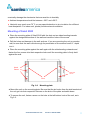
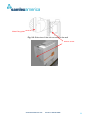
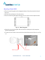
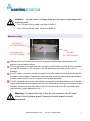
1
110-17 Fawcett Rd T: 604 525 3836 Coquitlam, B.C. F: 604 525 5221 Canada V3K 6V2 e-mail: [email protected] website: www.samlexamerica.com Grid Tie DC-AC Inverter Pure Sine Wave Model: Soleil 2000-120 Soleil 2000-240 093-2009 Soleil 2000 Manual Owner's Manual Please read this manual before operating your Inverter IMPORTANT SAFETY INSTRUCTIONS SAVE THESE INSTRUCTIONS To reduce the risk of electrical shock and to ensure safe installation and operation of Soleil 2000, please carefully read and strictly follow all safety instructions and cautionary markings. Warning : This marking indicates very important safety warning for user to appropriately apply during installation or operation. Warning : All electrical installation shall be done in accordance with local and National Electrical Codes ANSI/NFPA 70. Warning : Connecting this unit to the electrical grid shall only be performed by qualified personnel and only after formal approval from the utility company. Warning : This device contains no user serviceable parts inside. Please return the unit to authorized Service Center for maintenance. Warning : To reduce the risk of fire, do not connect to an AC load center (circuit breaker panel) having multi-wire branch circuits connected. Caution : AC disconnect breaker should be installed for over-current protection. Caution : Top & rear heat sink of this unit may exceed 70 °C. Don’t touch to avoid risk of burning. Caution : This unit should be mounted on firm background and avoid exposure to direct sunlight and rain. www.samlexamerica.com Toll free 1-800-561-5885 2 Caution : This unit is provided with fixed trip limits and shall not be aggregated above 30kW on a Single Point of Common Connector. Caution : The AC output of this unit is not bonded to ground. Caution : The input and output circuits are isolated from the enclosure. System grounding, when required by Sections 690.41, 690.42, and 690.43 of the National Electric Code, ANSI / NFPA 70, is the responsibility of the installer. www.samlexamerica.com Toll free 1-800-561-5885 3 Table of contents 1. Introduction ……………………………………………………. 5 2. Installation …………………………………………………...... 6 3. Wiring process …………………………………………………10 4. Operating procedure…………………………………………..15 5. System Structure……………………………………………… 21 6. Electrical Specifications……………………………………….20 7. Trouble shooting………………………………………………..24 www.samlexamerica.com Toll free 1-800-561-5885 4 1. Introduction Product features Full DSP digital control PV Module Wp=2.5kW Power output capacity: 2KW/120Vac 60Hz Maximum power conversion efficiency >94% (without Isolation Transformer) High efficiency maximum power point tracking function LCD displays system function and power generating status Real time network monitoring and recording function Computer can perform system setup of photovoltaic inverter and recording of power generating information via RS-232 interface during maintenance Quiet and efficient operation Easy to install with pleasing aesthetic styling System introduction The system is a single stage parallel circuit photovoltaic inverter. As opposed to traditional photovoltaic inverters, no expensive and bulky batteries are required. Hence, eliminating large expenses on battery maintenance. It can convert photovoltaic DC energy via solar panel modules and inverts collected energy into alternate current, which is then fed directly into the power grid. Such design can benefit from both direct power generating and energy conservation. The control panel adopts Digital Signal Processor (DSP), with the most advanced digital control technology, to increase power conversion efficiency and supplementary functions. Output stage circuit is of single stage with high frequency switchable IGBT. The circuit design has the advantage of being both simple and high efficiency. PV inverter system can be monitored remotely via software. It provides users with convenient power monitoring and recording functions without the need of additional monitoring systems. www.samlexamerica.com Toll free 1-800-561-5885 5 2. Installation Warning : All electrical installation shall be done in accordance with local and national codes ANSI/NFPA 70. Warning : Connecting the Soleil 2000 to the electrical grid shall only be performed by qualified personnel and only after formal approval from the utility company. Caution : For proper circuit isolation, use 2.0KW rated isolating transformer model SYST1201 supplied by Samlex Solar between the output of the unit and the utility power line connection. Placement of Soleil 2000 Soleil 2000 can be installed indoor where sufficient air circulation is available with ambient temperature less then 50℃. Outdoor installation should be under controlled environment where no direct sunlight would reach, as excessive heating would damage internal components and should minimize exposure to rain despite her high protection class IP 65 ( NEMA 3R). The unit should be installed in a location normally inaccessible to persons. Avoid mounting on wall of resonant materials like wooden or plastic panels as Soleil 2000 may slightly vibrate when working under load. Please install this unit at eye-height (over 1 meter), so that all information and status from LCD display can be read easily. Also please provide sufficient space on both sides of the unit so that Cautions and Ratings would be easily visible. Mount only on firm background and with correct position as below : Fig. 2-1 mount straight or tilted to the back never mount tilted to front Outdoor Installation shall not proceed on rainy day. High humidity within the unit may www.samlexamerica.com Toll free 1-800-561-5885 6 eventually damage the electronics that are sensitive to humidity. Ambient temperature should be between –20°C and +50°C. Heat sink may reach over 70 oC, so pay special attention to air circulation for sufficient heat dissipation. For indoor unit, please provide external ventilation. Mounting of Soleil 2000 Place the mounting plate of Soleil 2000 with the slots on two sides bending inwards against the designated surface of the wall and mark the holes of the screw. Drill the holes and hammer in the wall anchors. If you are mounting the unit on wooden wall, be sure that the wall is thick enough for penetration of the screws 1and1/2 “ depth into it. Place the mounting plate against the wall again with the slots bending outwards and fasten the four screws into their respective holes until the mounting plate is firmly held against the wall. Hook fixture Hole for screw Slots Fig. 2-2 Mounting plate Mount the unit on the mounting plate. Be sure that the six hooks from the side brackets of the unit get into their respective fixtures on the slots of the plate and settle down. To secure the unit, fasten a screw on the hole at the left bottom hook of the unit, as in Fig 2-3. www.samlexamerica.com Toll free 1-800-561-5885 7 Metal fixing plate Fig. 2-3: Side view of the unit mounting to the wall Secure screw www.samlexamerica.com Toll free 1-800-561-5885 8 Mounting of Soleil 2000 Place the metal fixing plate on the designated surface of the wall and mark the holes of the screw. Drill the holes and hammer in the wall anchors. Place the metal fixing plate again and fasten the four screws into their respective holes Fig. 2-2 Metal fixing plate Mount the unit on the fixing plate. Be sure that the six hooks get into their respective fixtures and settle down. To secure the unit, fasten a screw on the hole at the left bottom hook of the unit, as in Fig 2-3. Metal fixing plate www.samlexamerica.com Secure screw Toll free 1-800-561-5885 9 3. Wiring process The photovoltaic inverter wiring is as shown above. Warning : National Electrical Code (NEC) requires that the inverter be connected to a dedicated circuit and no other outlets or device may be connected to this circuit. See NEC Section 690-64(b) Warning : Follow local electrical codes and the National Electrical Code (NEC), ANSI/NFPA 70. Use copper conductors only with minimum 12 AWG, 105℃, 600V wire for all connections with the Soleil 2000. Power cable selection AC wire: Black copper wires of 12 AWG or above should be used for alternate current output. Ground wire: For enclosure grounding, green or yellowish green copper wires of 12AWG or above should be used. DC wire: For input to the unit from solar panels, the cross section area is dependent on the length of the wire. Identifiable colored copper wires of 12 AWG or above, for both positive and negative power supplies should be used. www.samlexamerica.com Toll free 1-800-561-5885 10 Caution : Longer wire or Voltage drop would require that larger wire sizes be used. For a 70 feet (16.4 m) cable, use size of AWG 12 For a 100 feet (33 m) cable, use size of AWG 10 Notes for wiring AC Output 1/2” TSC knockout Communication 1/2” TSC knockout DC Input 3/4” TSC knockout Make sure the unit is fixed securely and all power switchboards are switched to off position to avoid electric shock. This unit provides a terminal block for connections at DC Input terminal and is to connect through DC knockout to PV string from the DC disconnect (schottky diode + circuit breaker). For AC output, connection should be made from the AC output terminal block through AC knockout to the Isolation Transformer and there after to AC disconnect and main breaker. Excess power would be fed to the grid via a dual rate flow meter. The AC equipment-ground wire should be connected from the ground terminal on the AC output terminal block and together with AC Line & Neutral, go through AC knockout to the Isolation Transformer and there after to the Ground terminal of the AC disconnect and main breaker ( power distribution unit ). Warning : To reduce the risk of fire, do not connect to an AC load center (circuit breaker panel) having multi-wire branch circuits connected. www.samlexamerica.com Toll free 1-800-561-5885 11 Connecting AC Wiring Make sure AC Main Breaker is at OFF position. Install a 1/2 inch conduit fitting to the AC knockout at the left side of the Soleil 2000. Install two 1/2 inch conduit fittings respectively to the two knockouts at the bottom of isolation transformer located just left side of the Soleil 2000. Install a 1/2 inch conduit between the AC knockout of the unit and the INV knockout that sits right of the Isolating Transformer. Also between the transformer and AC disconnect AC disconnect breaker should be installed for over-current protection. Pull the AC wires through the conduit from the Isolating Transformer to the interior of Soleil 2000. Connect the AC Ground wire to the terminal labeled Ground with marking on the AC terminal block that sits right besides the AC conduit fitting. Connect the AC Line wire to the terminal labeled Line on the terminal block in the unit. Connect the AC Neutral wire to the terminal labeled Neutral on the same terminal block. Connect the other ends of AC Line and Neutral wires to the Isolating Transformer, Connect the other end of Ground wire to the Ground terminal of Isolating Transformer. Connect the AC & Ground wires through conduit between Isolating Transformer and AC disconnect breaker. All the wires should be connected correctly and tightened to a torque of 18 in-lb. www.samlexamerica.com Toll free 1-800-561-5885 12 Ground DC Input AC Output Connecting DC Wiring Make sure that AC main breaker and DC disconnect breaker are at OFF position. Install a 3/4 inch conduit fitting to the DC knockout at the right side of the Soleil 2000. Install a 3/4 inch conduit between the DC knockout and the DC disconnect breaker panel. Pull the DC wires through the conduit from the interior of DC disconnect panel to the interior of Soleil 2000. Connect the positive DC wire to the terminal labeled PV+ on the terminal block in the unit. Connect the negative DC wire to the terminal labeled PV - on the terminal block in the unit. Connect the other ends of the positive and negative wires in the DC disconnect panel to their respective terminals. All the wires should be connected correctly and tightened to a torque of 18 in-lb Connecting Communication Cable Soleil 2000 provides optional RS-232 or TCP/IP communication ports for maintenance. The communication cable can be installed at the same time while installing the inverter or some time later. Details see in Monitoring and setup section. 1/2 inch conduit may be required for communication wiring per local electrical code requirement. Run the communication cable from the location of PC to the interior of Soleil 2000 through the Communication knockout on the middle of Soleil 2000. www.samlexamerica.com Toll free 1-800-561-5885 13 Connect the cable to the appropriate port of the communication PWB in the unit. Connect the other end of the cable to the appropriate port of the PC. Make sure the conduit fitting or cable grand on the knockout is sealed and safe from rain Replacing the cover After AC, DC and Communication wires are all connected, make sure the Isolation sheet with cautionary markings covers over the power circuitry below and no pressure will be exerted on any connections when the cover is fixed. Position the cover on the Soleil 2000 carefully and align the four holes on the cover to the threaded holes of the brass threaded spacers on the enclosure. Carefully insert the four screws previously removed to take the cover off through the nylon washers and the aligned holes and fasten them till they are finger-tight. After verifying that the front cover is in correct position and the seal well in place, fasten all screws till firmly tight. Warning : Never install the Soleil 2000 during rainy day. Moisture trapped inside the enclosure during those very damp conditions would damage the sensitive electronic components. www.samlexamerica.com Toll free 1-800-561-5885 14 4. Operation Warning : Connection between the Soleil 2000, the PV string and the utility grid must be done in the order described bellow. Operation ignoring the order will cause hazardous accident. Start operation Verify all breakers are at OFF position. Use an electricians’ multi-meter to test and make sure that the input voltage at DC disconnect is within the correct range (200-450VDC). Check both the voltage and frequency of main power grid is within the normal range. Connect the Soleil 2000 to the utility by switching on AC Main breaker and AC disconnect breaker. Connect the Soleil 2000 to PV strings by switching on DC disconnect breaker. After switching on the system, the Soleil 2000 will start boot up sequence. It will take a few minutes to complete the self-test cycle, as well as confirmation of power grid voltage and frequency. After confirming the AC voltage is within the correct working range, sunbeams can start generating electrical power for user’s household electrical appliance and excess power will be fed to utility grid automatically. www.samlexamerica.com Toll free 1-800-561-5885 15 Monitoring and setup RS-232Use standard DB9 cable to connect serial port on the computer to that on the machine. After complete setting of COM Port following Monitoring Software, it is ready to start monitoring and setting up the photovoltaic inverter. For monitoring and setting up the photovoltaic inverter, please refer to the “Monitoring software manual”. TCP/IP ( Optional ) Set up according to Monitoring software manual attached with the network card. RJ-45 Port RS232 Port www.samlexamerica.com Toll free 1-800-561-5885 16 Control Panel Switch ON photovoltaic inverter Switches the photovoltaic inverter ON. Switch ON photovoltaic inverter When solar panel input voltage reaches the required range for starting, press this button for a few seconds until a buzzing sound is audible. Release the button. LCD panel will show the starting screen. After power grid detection runs for 5 minutes and remains in “normal” condition, photovoltaic energy will start to feed-in electric current. “UP” shifting button Recursive “UP” movements show: Accumulate power Input voltage / power Output voltage / power “Down” shifting button Recursive “DOWN” movements show: Accumulate power Output voltage / power Input voltage / power 17 Status reports from LCD Boot up screen Pic -1 1. Switch on the power grid circuit breaker, the screen shows “Ver. 10”(Pic-1) 2. DSP initial boot up sequence completed as shown on (Pic-2), notified by half a second “beep” sound. The system is ready and enters idle mode. Pic – 2 System initial screen Pic - 3 Pic - 4 Pic - 5 Pic - 6 1. Under initial mode, the system starts detecting the voltage and frequency of the solar module and power grid. after 2 seconds, 2. The screen shows “Counter 300 sec.”, and countdown. If the input voltage (190<Vpv<450V), output voltage (106<Vac<132V) and frequency (59.3<Fac<60.5Hz) are all within operating range, the system will initiate a 5-minute countdown and prepare to start. (Pic-3) 3. If the voltage of solar module voltage is too low (Vpv<190V), or AC voltage too low (Vac<106V), the screen shows “Start waiting . . .” to indicate wrong voltage (Pic-4). 4. If the frequency is out of range, the screen shows “AC FREQ error” to indicate wrong frequency. (Pic-5). 5. If the voltage of solar module is too high (Vpv>450V), or AC voltage is too high (Vac>132V), the screen shows “Over voltage” to indicate wrong voltage (Pic-6). 6. If the voltage of power grid and solar module are abnormal, the system will remain at monitoring voltage initial mode as shown on both (Pic-4) and (Pic-5). In the mean time all buttons are disabled and not functional. 16 MPPT Mode Pic-7 Pic - 8 1. Under the initial mode, after pressing “POWER” button for more than 3 seconds, or, after DSP takes 5 minutes to detect and confirm that the voltages of power grid and solar module are in operating range, the unit will beep for 1.5 seconds and switch on the system. The system would be in “ MPPT MODE” then and the screen display as Pic-7. 2. During the starting sequence, the system requires some time for voltage tracking and the phase to lock to parallel network. It will spend 10 seconds to enter MPPT mode. After entering MPPT mode, the unit starts power producing. The screen display Data monitoring as : Total Power Pv Power Ac Power, every 2 seconds in turn. ( Pic-8, Pic-9, Pic-10 ) Pic - 9 Pic – 10 Pic- Sleep Data Monitoring 1. The displays data on the screen can also be changed by pressing “UP” or “DOWN” buttons to shift the rows of displays. Accumulate:Total=0000002kWH today=0000001kWH Input status : Vpv =319V Ppv =1423W Output status : Vac=120V Pac=1416W 2. Press “UP” button to shift displays upwards 3. Press “DOWN” button to shift displays downwards. LCD Sleep Mode 1. During normal operation, if none of the buttons is pressed within 5 minutes, the LCD display would automatically enter her sleep mode. A single black spot would be seen on the screen shifting from left side to right side one space per second. (Pic-Sleep) 2. 3. Pressing any button will wake up the screen display. www.samlexamerica.com Toll free 1-800-561-5885 19 Protection mode fault display Pic - 11 Pic - 12 Pic - 13 1. Under conditions as voltage too high, current overflow or inappropriate frequency, the unit will switch off PWM immediately and relay jump off to enter fault mode as shown on (Pic-11) to (Pic-16). A. When Input/ output current overflow, screen displays Fault Over current (Pic-11) When over load, screen displays Fault Over load (Pic-12) B. When output frequency abnormal, screen displays Waiting … AC FREQ error (Pic-13) When Power grid voltage too high / low, screen displays Waiting … Utility error (Pic-14) When input voltage abnormal, screen displays Waiting … MPPT on (Pic-15) C. When sun set, the unit would shut down and screen displays as Pic-16 2. When “island effect” is determined, Power Supply will shutdown. After power grid is restored, a 5-minute countdown starts. The system will jump to initial mode for starting once the countdown is complete. Pic – 14 Pic-15 Pic-16 20 5 System structure System structure block diagram System structure can be divided into the following sections: 1. Inverter: By using SPWM control and parallel circuit control technology, the inverter can invert electricity from DC into AC and feeds current into AC grid directly. 2. Inverter control interface: DSP control interface provides control signals including A/D control, I/O control, PWM drive and protection signals. With the support of control interface, users can control and monitor and maintain the entire system. 3. Power supply control: The design can provide required power supplies for DSP and other components on the digital circuits, analogue circuits, gate level drive and communication interface. 4. Human interface control panel The control panel has control buttons and LCD shows control status. www.samlexamerica.com Toll free 1-800-561-5885 21 6. Electrical specifications Item Architecture PV Input Data Description Converter Topology Full-Bridge DC-AC converter Control Processor DSP (TI TMS320LF2407A, 40MHz) Maximum Input voltage 450Vdc Voltage Range 200~360Vdc (120V mode) Grounding DC Negative ground Input Current Ripple < 200mA Number of Phase Single Phase Nominal Output Voltage ■120Vac Output Voltage Follows transformer-less 106~132, of grid voltage and tripping Output Current THD < 5% at rated output power Power Factor > 0.99 at full load Frequency Range 59.3~60.5Hz Efficiency 94% without Isolation Transformer Output Power Capacity 2KW Max Current 18A Communications RS-232 build-in Remote Control Dry Contact TCP/IP TCP/IP Adapter Comment AC Output Maintenance Interface Interactive Rating Maximum input short circuit current Maximum input source backfeed current to input source Maximum output fault current Maximum output current protection Utility interconnection voltage / frequency trip limits and trip times Synchronization in-rush current Trip limit and trip time accuracy 15A 17.5A 25A 18A 0.16 sec / 102.3 ms 850mA 100 ~ 108 ms www.samlexamerica.com Toll free 1-800-561-5885 22 Item Data Description Anti-Islanding Comment Yes DC Input Over Voltage Yes and Under Voltage Input Over Current Yes AC Output Over Voltage Yes and Under Voltage Output Over Current Protection Yes DC Ground Fault Detect Yes and Interruption Current Limiting Yes Power Limiting Yes Frequency Decrease Yes and Frequency Increase Internal Shutdown Internal protection tripping relay Surge immunity IEEE C62.41.2 : 2002 Location category C Low Input Power Control Maximum Power Point Tracking (MPPT) System Control Power Control External Fault Test Features Environmental Size Product Regulations Control Type Automatic grid AC voltage sensing Automatic recovery after grid failure Current control, microprocessor assisted output regulation Control Hardware Platform DSP Power Hardware Platform IGBT-based inverter Short Circuit Yes Heat Dissipation Convection Display LCD Display Operating Temperature -20℃~50℃ Storage Temperature -20℃~50℃ Relative Humidity 0~95% Non-condensing Altitude 10,000ft (3000m) Audible Note < 45 dB at 1m Dimensions (mm) L382*W175*H398 Weight (kg) 15kg Safety EMC UL1741-2005 IEEE 1547.1-2005 FCC Part15 Class B 7.Trouble shooting Problem OVER CURRENT Possible causes How to correct Output/Input current Check the output stage of PV inverter for short over supply circuit or inappropriate wiring Check if PV Inverter is placed in a well-ventilated area LINE FREQ ERROR Power grid Check the connection of plugs to the power frequency abnormal grid Check the power grid frequency is normal PV VOLTS ERROR Input voltage of solar Check voltage on the solar module is within power module too operating range (200-360V) low Check there is sunlight available (avoid evening, dawn, late evening, cloudy or rainy days) Check the solar module is not being covered up by any objects (leaves, buildings etc.) UTILITY ERROR Can not detect voltage from power grid or is abnormal www.samlexamerica.com Check connection between PV inverter and power grid Check power grid voltage is normal (not too high or too low) Toll free 1-800-561-5885 24 110-17 Fawcett Rd T: 604 525 3836 Coquitlam, B.C. F: 604 525 5221 Canada V3K 6V2 e-mail: [email protected] website: www.samlexamerica.com Grid Tie DC-AC Inverter Pure Sine Wave Model: Soleil 2000-120 Soleil 2000-240 093-2009 Soleil 2000 Manual Owner's Manual Please read this manual before operating your Inverter