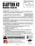
1
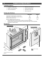
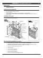
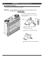
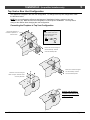
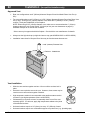
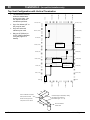
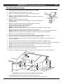
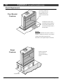
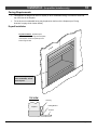
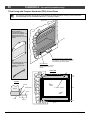
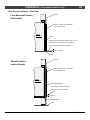
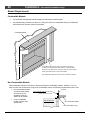
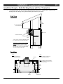
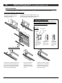
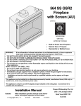
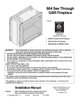
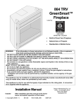
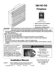
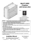
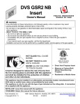
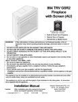
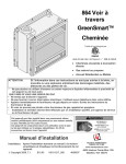
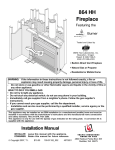
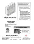
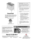
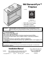
564 Diamond-Fyre™
Fireplace
Listed by
AS 4553-2008
GMK10022
IAPMO-R&T OCEANA
•
Built-In Direct Vent Fireplace
•
Natural Gas or Propane
Residential or Mobile Home
•
WARNING:
If the information in these instructions is not followed exactly, a fire or
explosion may result causing property damage, personal injury or loss of
life.
- Do not store or use gasoline or other flammable vapors and liquids in the vicinity of this
or any other appliance.
WHAT TO DO IF YOU SMELL GAS
• Do not try to light any appliance.
• Do not touch any electrical switch; do not use any phone in your building.
• Immediately call gas supplier from a neighbor's phone. Follow the gas supplier's
instructions.
• If you cannot reach your gas supplier, call the fire department.
- Installation and service must be performed by a qualified installer, service agency or the
gas supplier.
This appliance may be installed in an aftermarket permanently located, manufactured home (USA only) or
mobile home, where not prohibited by local codes.
This appliance is only for use with the type(s) of gas indicated on the rating plate. A conversion kit is
supplied with the appliance.
Installation Manual
Installer:
Dragon Wholesaling Pty. Ltd.
After installation give this manual to the homeowner and explain operation of this heater.
© Copyright 2010, T.I.
$10.00
100-01257_000
4101014
Unit 2, 16 Lexington Drive
Bella Vista NSW 2153
Australia
2
Introduction
Overview
This manual details the installation requirements
for the 564 DF fireplace. For operating and
maintenance instructions, refer to the 564 DF
Owner's Manual (part # 100-01258).
Listing Details
This appliance was listed by SAI Global to AS
4553-2008. The listing label is attached to the
appliance near the gas control valve.
© Travis Industries
4101014
100-01257_000
Table of Contents
Introduction
Installation (continued)
Overview ............................................................................. 2
Listing Details ...................................................................... 2
Safety Precautions
Safety Precautions .............................................................. 4
Features and Specifications
Features .............................................................................. 6
Installation Options.............................................................. 6
Heating Specifications ......................................................... 6
Dimensions ......................................................................... 6
Hearth Requirements .......................................................... 32
Facing Requirements .......................................................... 33
Drywall Installation .......................................................... 33
Facing Overview ............................................................. 34
Optional Faceplates – Sizing Chart ................................. 34
Thin Facing Installation ................................................... 35
Thick Facing Installation .................................................. 37
Thick Facing Installation with FPX Arched Faces............ 38
Mantel Requirements .......................................................... 40
Install Example - Build-Out (Dog-House) w Hor. Term. ...... 41
Install Example - Build-In w Hor. Term................................ 42
Finalizing the Installation
Installation
Packing List ......................................................................... 7
Additional Items Required ................................................... 7
Installation Overview ........................................................... 7
Recommended Installation Procedure ................................ 7
Top Stand-Off Assembly ..................................................... 8
Converting the Fireplace to Top Vent Configuration ........... 9
Fireplace Placement Requirements .................................... 11
Clearances ...................................................................... 11
Raised Fireplaces ............................................................ 11
Min. Framing Dims. - Rear Vent Configuration ...........................12
Min. Framing Dims. - Top Vent Configuration ................. 13
Nailing Brackets .............................................................. 14
Corner Installations - Rear Vent Configuration ................ 15
Corner Installations - Top Vent Configuration .................. 16
Gas Line Requirements ...................................................... 17
Fuel ................................................................................. 17
Gas Line Connection ....................................................... 17
Gas Inlet Pressure ........................................................... 17
Gas Line Location............................................................ 17
Electrical Connection (required) .......................................... 19
Optional Wall Switch or Thermostat Installation .................. 20
Vent Requirements ............................................................. 21
Vent Clearances .............................................................. 21
Altitude Considerations.................................................... 21
Approved Vent ................................................................. 22
Vent Installation ............................................................... 22
Approved Vent Configurations ............................................ 23
Restrictor Position ........................................................... 23
Exhaust Restrictor Adjustment ........................................ 23
Intake Restrictor Adjustment ........................................... 24
Diffuser Plate Adjustment ................................................ 25
Rear Vent Config. W Horizontal Term. (no vertical rise) ..... 26
Rear Vent Config. W Horizontal Term. (w vertical rise) ....... 27
Rear Vent Configuration with Vertical Termination .............. 28
Top Vent Configuration with Horizontal Termination ........... 29
Top Vent Configuration with Vertical Termination ............... 30
Termination Requirements .................................................. 31
© Travis Industries
3
Air Shutter Adjustment .................................................... 44
Glass Frame Removal and Installation ............................... 45
LP Conversion Instructions ................................................. 52
Optional Equipment
Grill Installation ................................................................... 56
Index
Index ................................................................................... 58
4101014
100-01257_000
4
Safety Precautions
Safety Warnings:
•
Failure to follow all of the requirements may result in property damage, bodily injury, or even death.
•
This unit must be installed by a qualified installer to prevent the possibility of an explosion.
•
This appliance must be installed in accordance with all local codes, if any; if not, in U.S.A. follow
ANSI Z223.1 and NFPA 54(88).
•
A manufactured home (USA only) or mobile home OEM installation must conform with the
Manufactured Home Construction and Safety Standard, Title 24 CFR, Part 3280, or, when such a
standard is not applicable, the Standard for Manufactured Home Installations, ANSI/NCSBCS
A225.1, or Standard for Gas Equipped Recreational Vehicles and Mobile Housing, CSA Z240.4. This
appliance may be installed in Manufactured Housing only after the home is site located.
•
All exhaust gases must be vented outside the structure of the living-area. Combustion air is drawn
from outside the living-area structure. The venting must not be connected to a chimney flue serving a
separate solid-fuel burning appliance.
•
Notify your insurance company before hooking up this fireplace.
•
The room heater should be inspected before use and at least annually by a qualified service person.
More frequent cleaning may be required due to excessive lint from carpeting, bedding material, etc.
•
The instructions in this manual must be strictly adhered to. Do not use makeshift methods or
compromise in the installation. Improper installation will void the warranty and safety listing.
•
This heater is approved for use with natural gas (NG) or propane (LP). Burning the incorrect fuel will
void the warranty and safety listing and may cause an extreme safety hazard. Direct questions about
the type of fuel used to your dealer. Check the label and flame adjust knob on the gas control valve.
•
Contact your local building officials to obtain a permit and information on any installation restrictions
or inspection requirements in your area.
•
If the flame becomes sooty, dark orange in color, or extremely tall, do not operate the heater. Call
your dealer and arrange for proper servicing.
•
It is imperative that control compartments, screens, or circulating air passageways of the heater be
kept clean and free of obstructions. These areas provide the air necessary for safe operation.
•
Do not operate the heater if it is not operating properly in any fashion or if you are uncertain. Call
your dealer for a full explanation of your heater and what to expect.
•
Do not store or use gasoline or other flammable liquids in the vicinity of this heater.
•
Do not operate if any portion of the heater was submerged in water or if any corrosion occurs.
•
Do not place clothing or other flammable items on or near the heater. Because this heater can be
controlled by a thermostat there is a possibility of the heater turning on and igniting any items placed
on or near it.
•
Light the heater using the built-in igniter. Do not use matches or any other external device to light
your heater.
•
Never remove, replace, modify or substitute any part of the heater unless instructions are given in this
manual. All other work must be done by a trained technician. Don't modify or replace orifices.
•
The viewing glass should be opened only for conducting service.
•
Any safety screen or guard removed for servicing must be replaced prior to operating the heater.
Travis Industries
4101014
100-01257_000
Safety Precautions
5
Safety Warnings (continued):
•
Do not place articles on or against this appliance.
•
Do not use or store flammable materials near this appliance.
•
Do not spray aerosols in the vicinity of this appliance while it is in operation.
•
Do not modify this appliance
•
Servicing shall be carried out only by authorized personnel.
•
Allow the heater to cool before carrying out any maintenance or cleaning.
•
Operate the heater according to the instructions included in this manual.
•
If the main burners do not start correctly turn the gas off and call your dealer for service.
•
This unit is not for use with solid fuel.
•
Do not place anything inside the firebox (except the included components).
•
Do not throw this manual away. This manual has important operating and maintenance instructions
that you will need at a later time. Always follow the instructions in this manual.
•
Do not touch the hot surfaces of the heater. Educate all children of the danger of a high-temperature
heater. Young children should be supervised when they are in the same room as the heater.
•
Due to the high temperature, the heater should be located out of traffic and away from furniture and
draperies.
•
Instruct everyone in the house how to shut gas off to the appliance and at the gas main shutoff valve.
The gas main shutoff valve is usually next to the gas meter or propane tank and requires a wrench to
shut off.
•
Travis Industries, Inc. grants no warranty, implied or stated, for the installation or
maintenance of your heater, and assumes no responsibility of any consequential damage(s).
© Travis Industries
4101014
100-01257_000
6
Features and Specifications
Installation Options
•
Residential or Mobile Home
•
Raised or Floor Placement
•
Straight or Corner Placement
•
Internal or External Chase
•
Flush or Recessed Face
•
Horizontal or Vertical Vent
•
Bedroom Approved
Heating Specifications
Natural Gas
Propane
Approximate Heating Capacity (in square feet)*
950
950
Approximate Heating Capacity (in square meters)*
88
88
20,500
20,500
21.6
21.6
Maximum BTU Input Per Hour
Maximum Megajoules (MJ) Input Per Hour
*
**
Heating capacity will vary with floor plan, insulation, and outside temperature.
Efficiency rating is a product thermal efficiency rating determined under continuous operation
independent of installed system.
Dimensions
Top Vent Configuration
8" (203mm) Diameter Vent
4-3/4"
Rear Vent Configuration
121mm
8" (203mm) Diameter Vent
33-1/4"
845mm
31-3/4"
794mm
30-1/4"
768mm
28-3/4"
730mm
18-3/4"
32-1/2"
ce
pla
476mm
826mm
ck
of
e
Fir
Ba
1"
25mm
30"*
762mm
24-1/4"
616mm
ht
Rig
36-1/4"
921mm
16-1/4"*
413mm
ft
Le
Fro
nt
Weight: 155 Lbs. (70.4kg)
* Includes the required 1/2" (13mm)
clearance.
Travis Industries
4101014
100-01257_000
Installation
7
(for qualified installers only)
Packing List
•
•
Propane Conversion Kit
Firestop (sku 250-00747)
Additional Items Required
•
•
•
•
•
•
Direct Vent
Gas Line Equipment (shutoff valve, pipe, etc.)
Electrical Equipment
Crushed Glass (Platinum 94500580 – Bronze 94500581 – Cobalt 94500582)
564DF Firebacks (Stainless Steel 96100208 - Black Enamel 96100210 - Painted Black 96100211)
Face or Grill Kit
Installation Overview
•
All requirements below must be met.
Top Vent
Configuration
See the section
See the section
"Vent Requirements"
Rear Vent
Configuration
"Mantel Requirements"
See the section
"Approved Vent
Required
Travis
Firestop (sku
250-00747)
Configurations"
Insulation must not fill
the 1/2" (13mm)
Side
Wall
Drywall
clearance around the
Drywall
1" Min.
25mm
back and sides of the
fireplace.
Nailing Brackets
See the section "Minimum
Framing Dimensions"
See "Optional NonCombustible Facing"
See "Optional NonCombustible Hearth"
See the section
See the section
"Gas Line Installation"
"Electrical Connection"
Recommended Installation Procedure
•
Frame the opening for the fireplace. Make sure to allow for vent installation.
•
This fireplace is designed to accommodate 1/2" (13mm) or 5/8" (16mm) drywall (see "Nailing
Brackets" on page 14 for details). Secure the fireplace to the framing.
•
Install the vent, gas line and electrical hook-up.
•
Install the drywall.
•
Install the hearth (if applicable).
•
Install the facing (if applicable).
•
Install the mantel (if applicable).
•
Finalize the installation and install the grill or face.
© Travis Industries
4101014
100-01257_000
8
Installation
(for qualified installers only)
Top Stand-Off Assembly
The top stand-offs must be assembled prior to installation.
Warning:
You must follow the instructions below to elevate both standoffs. Failure to
do so will result in an extreme fire hazard.
The standoffs are shipped in the flat position.
Make sure to follow the instructions below before
installing the fireplace.
2
AFTER
Standoff
1
3
1/4" Nutdriver
BEFORE
a Bend the standoff in the numbered
sequence shown above.
b Remove the screw below the standoff.
c
Travis Industries
4101014
Replace the screw to secure the standoff.
100-01257_000
Installation
9
(for qualified installers only)
Top Vent or Rear Vent Configuration
This appliance is shipped in the rear vent configuration. To change to the top vent configuration, follow
the directions below.
NOTE: the vent configuration affects several aspects of installation (framing, maximum vent rise,
maximum vent run). Make sure the vent configuration is correct prior to installation. You may wish to
configure the diffuser when changing the vent configuration.
Converting the Fireplace to Top Vent Configuration
NOTE: Use a magnetic-tipped
Remove and discard the
nutdriver on these screws - take
heat shield. Replace the 4
care to prevent the screws from
removed screws.
falling into the fireplace.
ce
pla
ire
fF
o
op
T
Remove the 4 screws securing the
ck
Ba
ce
pla
ire
F
of
outer flue assembly. Place the
screws and assembly aside.
Remove the 4 screws securing the
inner flue assembly. Place the
Remove the 4 screws securing the
screws and assembly aside.
intake cover plate. Place the screws
and cover plate aside.
Remove and discard the
insulation found below the
large cover plate.
© Travis Industries
4101014
100-01257_000
10
Installation
(for qualified installers only)
Converting the Fireplace to Top Vent (continued)
Remove the 4 screws securing the
exhaust cover plate. Verify the gasket
on the cover plate is in place, then
attach it to the rear-facing exhaust
port with the same screws.
Verify the gasket on the intake cover
plate is in place, then attach it to the
rear of the fireplace using the screws
removed earlier.
Verify the gasket on the inner flue
assembly is in place, then attach it to
the upward-facing exhaust port using
the screws removed earlier.
Verify the gasket on the outer flue
assembly is in place, then attach it to
the top of the fireplace using the
screws removed earlier.
Travis Industries
4101014
100-01257_000
Installation
11
(for qualified installers only)
Fireplace Placement Requirements
•
The fireplace requires a 1/2" (13mm) clearance from the angled sides and back of the fireplace to the
framing members. No material (insulation, framing, etc.) may be placed into this area.
•
Fireplace must be installed on a level surface capable of supporting the fireplace and vent
•
Fireplace must be placed directly on wood or non-combustible surface (not on linoleum or carpet)
•
This heater may be placed in a bedroom. Please be aware of the large amount of heat this appliance
produces when determining a location.
Clearances
•
When installed, walls in front of the fireplace must be a minimum 1" (25mm) to the side of the
fireplace.
•
Due to the high temperature, the heater should be located out of traffic and away from furniture and
draperies.
•
Fireplace must be placed so the vents below and above the glass do not become blocked.
Raised Fireplaces
•
The fireplace (and hearth, if desired) may be placed on a platform designed to support the fireplace
(155 Lbs.70 Kg) and vent.
© Travis Industries
4101014
100-01257_000
12
Installation
(for qualified installers only)
Minimum Framing Dimensions - Rear Vent Configuration
Included Firestop (required)
HINT: place the fireplace so the center
Part # 250-00747
line is at least 5" (127mm) from both
vertical framing members at the rear (this
allows the vent to pass through the
framing without modfications)
Vent Clearances for 8" (203mm) dia. Vent:
1" (25mm) to the sides, 1" (25mm) below,
and 4" (102mm) above the vent to
combustibles.
Center of Rear Vent
Minimum 38" (965mm)
24-1/4"
Fireplace Enclosure Height
32-1/2"
616mm
826mm
Route the
electrical line to
a position to the
19-1/4"
left rear of the
33-1/2"
fireplace.
851mm
489mm
36-1/2"
927mm
16-1/2"
419mm
The on/off switch/thermostat wire (if
used) should be routed to a location
near the right front of the fireplace.
Travis Industries
4101014
100-01257_000
Installation
(for qualified installers only)
13
Minimum Framing Dimensions - Top Vent Configuration
Route the electrical line to
a position to the left rear
of the fireplace.
33-1/2"
851mm
36-1/2"
16-1/2"
927mm
419mm
Minimum enclosure height = 36-1/4" (921mm)
The on/off switch/thermostat wire (if
used) should be routed to a location
WARNING: A cut-out for the gas line
near the right front of the fireplace.
may be required on the framing. See
the dimensions under "Gas Line
Connection" for details.
© Travis Industries
4101014
100-01257_000
14
Installation
(for qualified installers only)
Nailing Brackets
There are four nailing brackets
on the front of the fireplace.
Follow the directions below to
prepare the nailing brackets.
Once in place, nail or screw the
nailing brackets to the framing.
WARNING:
Make sure the fireplace is
square and plumb when
placed in the framing.
Measured corner-tocorner, the fireplace
should be square (approx.
47-1/8" (1197mm) for each
dimension). Use shims to
insure the fireplace is
square.
NOTE: Additional nailing
brackets are provided along
the base of the fireplace.
Use these brackets if not
using the front brackets.
TOP VIEW
1/2" (13mm)
Drywall
Framing
For installations using
1/2" (13mm) facing fold
the larger tab out 90°
(use a screwdriver if
necessary).
Fireplace
Nailing Bracket
Drywall
TOP VIEW
5/8" (0.625mm) Drywall
Framing
For installations using
5/8" (0.625mm) drywall
fold the shorter tab out
90° (use a screwdriver if
necessary).
Travis Industries
Fireplace
Nailing Bracket
Drywall
4101014
100-01257_000
Installation
15
(for qualified installers only)
Corner Installations - Rear Vent Configuration
A typical 45° installation uses the framing dimensions shown in the illustration below (NOTE: all
clearances still apply).
564 SS Firestop
Minimum 1" (25mm)
Clearance
Minimum 1/2" (13mm)
Clearance
7" (178mm)
Approximate
(varies due to vent
installation)
NOTE: Most installations
use:
6" (152mm) Section for 2x6
(51mm X 152mm) Walls
4" (102mm) Section for 2x4
(51mm X 102mm) Walls
44-1/2" Min.
1130mm
© Travis Industries
4101014
100-01257_000
16
Installation
(for qualified installers only)
Corner Installations - Top Vent Configuration
A typical 45° installation uses the framing dimensions shown in the illustration below (NOTE: all
clearances still apply).
Minimum 1/2" (13mm)
Clearance
14-1/4"
362mm
44-1/2" Min.
1130mm
Travis Industries
4101014
100-01257_000
Installation
17
(for qualified installers only)
Gas Line Requirements
•
•
•
The gas line must be installed in accordance with all local codes, if any; if not, follow ANSI 223.1 and
the requirements listed below.
The fireplace and gas control valve must be disconnected from the gas supply piping during any
pressure testing of that system at test pressures in excess of 1/2 psig. For pressures under 1/2 psig,
isolate the gas supply piping by closing the manual shutoff valve.
Leak test all gas line joints and the gas control valve prior to and after starting the fireplace.
Fuel
•
This fireplace is designed either for natural gas or for propane (but not for both). Check the sticker on the top of
the gas control valve to make sure the correct fuel is used.
Gas Line Connection
•
Installation must be performed by a qualified installer, service agency or the gas supplier (In Massachusetts a
licensed plumber/gasfitter).
Standard Input Pressure
Gas Inlet Pressure
Natural Gas
Propane
•
•
7" W.C. (1.74 kPA)
13" W.C. (2.73 kPA)
If the pressure is not sufficient, make sure the piping used is large enough, the supply regulator is adequately
adjusted, and the total gas load for the residence does not exceed the amount supplied.
The supply regulator (the regulator that attaches directly to the residence inlet or to the propane tank) should
supply gas at the suggested input pressure listed above. Contact the local gas supplier if the regulator is at an
improper pressure.
© Travis Industries
4101014
100-01257_000
18
Installation
(for qualified installers only)
Gas Line Location
Right Side Gas Inlet (preferred)
A 3" (76mm) high by 2" (51mm) wide opening is
A 6" (152mm) flex tube and shutoff
located behind the gas inlet cover plate. It is 7-3/4"
valve is included with the fireplace.
(197mm) behind the front and 1-3/4" (44mm) above
the base of the fireplace.
The shutoff valve accepts a 1/2"MPT.
8-3/4"
222mm
13-3/4"
349mm
The gas inlet is located 2-1/2"
(64mm) above the base of the
fireplace.
You may remove this cover plate to install the gas line. The
cover plate has a 7/8" (.0875mm) diameter hole (covered
with a push plug) in line with the gas inlet on the gas control
valve. By rotating the plate 180° the hole may be re-located.
You may also secure the plate in a customized location using
the self-drilling screws.
Left Side Gas Inlet
A 6" (152mm) flex tube and shutoff valve is
A 3" (76mm) high by 2" (51mm) wide opening is
included with the fireplace. You may wish to
located behind the gas inlet cover plate. It is 4-3/4"
use a 24" (610mm) flex tube. The shutoff valve
(121mm) behind the front and 1-3/4" (44mm) above
accepts a 1/2" MPT.
the base of the fireplace.
8-3/4"
222mm
You may wish to route the flex line along
13-3/4"
349mm
the front edge of the fireplace to conceal it.
You may remove this cover plate to install
the gas line. The cover plate has a 7/8"
(0.875mm) diameter hole (covered with a
push plug). By rotating the plate 180° the
hole may be re-located. You may also
secure the plate in a customized location
using the self-drilling screws.
Travis Industries
4101014
100-01257_000
Installation
19
(for qualified installers only)
Electrical Connection (required)
•
The electrical line must be installed by a qualified installer and must meet all local codes.
•
Make sure the household breaker is shut off prior to working on any electrical lines.
•
The appliance, when installed, must be electrically grounded in accordance with local codes or, in the
absence of local codes, with the National Electrical Code, ANSI/NFPA 70, or the Canadian Electrical
Code, CSA C22.1.
•
The electrical line must supply 240 Volts at 60 Hz (2 Amps).
Caution:
Label all wires prior to disconnection when servicing controls. Wiring errors can cause
improper and dangerous operation.
© Travis Industries
4101014
100-01257_000
20
Installation
(for qualified installers only)
Optional Wall Switch or Thermostat Installation
Do not connect 110-240 VAC to the gas control valve or wiring system of this fireplace. The switch
must be installed by a qualified installer.
This fireplace may be installed with an optional wall switch or thermostat. The thermostat (or on/off
switch) wire should be passed through the grommet on either side of the fireplace near the gas inlet (see
item “a” below). The thermostat (or on/off switch) wires will interrupt the burner circuit (see item “b”
below).
•
If you wish to bypass the switch, connect the thermostat (on/off switch) wires directly to the green and
white wires (see “c” below).
•
If you wish keep the switch (series) – re-align the wires as shown in item “d” below. NOTE: The
on/off switch must be in the “ON” position for the thermostat (or on/off switch) to operate.
Burner Circuit Wires
POWER SUPPLY
Black
Red
Black
Red
Red
Red
ON / OFF
Blue
Red
b
Green
White
Black
Blue
a
Thermostat
Wire
Grommet
AA
BATTERY
TRAY
COMFORT
CONTROL
c
Bypass
d
Thermostat or
MAIN
BURNER
Series
White
On/Off Switch
Thermostat or
Green
Green
On/Off Switch
White
Caution:
Label all wires prior to disconnection when servicing controls. Wiring errors can cause
improper and dangerous operation.
Note:
When using a GreenSmart™ remote, use the receiver for on/off operation.
Travis Industries
4101014
100-01257_000
Installation
21
(for qualified installers only)
Vent Requirements
•
The gas appliance and vent system must be vented directly to the outside of the building, and never
be attached to a chimney serving a separate solid fuel or gas-burning appliance. Each direct vent
gas appliance must use it's own separate vent system.
•
In addition to the requirements listed here, follow the requirements provided with the vent.
•
A firestop is required whenever the vent penetrates a wall, floor, or ceiling (passes through framing
members). Horizontal vent less than 48" (1219mm) above the fireplace must use the Travis Firestop
(sku 250-00747 - it incorporates a 4" (102mm) clearance above, 1"( 25mm)clearance below and to
the sides of the vent). Other penetrations only require a 1" (25mm) clearance and may use a
standard firestop (make sure the required 1" (25mm) clearance is met).
•
Always use the high-wind termination (if available from the vent manufacturer).
Vent Clearances
•
The vent must maintain the required clearance to combustible materials to prevent a fire. Do not fill
air spaces with insulation.
Before 48" (1219mm)
After 48" (1219mm)
Rise
Rise
Sides
1" (25mm)
1" (25mm)
Above
4" (102mm)
1" (25mm)
Below Horizontal or 45° Section
1" (25mm)
1" (25mm)
Vertical Termination
Horizontal
Required Firestop
Termination
Use a roof flashing and storm collar
whenever passing through the roof
Use a firestop whenever
Min. 4" (102mm)
passing through a ceiling
1" (25mm) if a minimum 48"
(1219mm) above the
Use a support box
on exposed vent
fireplace.
Min. 1"
25mm
Min. 1"
Min. 1"
25mm
25mm
Altitude Considerations
•
This heater has been tested at altitudes ranging from sea level to 6,000 feet (1800M). In this testing we have
found that the heater, with its standard orifice, burns correctly with just an air shutter adjustment.
•
Failure to adjust the air shutter properly may lead to improper combustion which can create a safety hazard.
Consult your dealer or installer if you suspect an improperly adjusted air shutter.
© Travis Industries
4101014
100-01257_000
22
Installation
(for qualified installers only)
Approved Vent
•
Rear vent configurations use 8" (203mm) diameter Simpson Dura-Vent Model Direct-Vent Pro (or
GS)*.
•
Top vent configurations use 8" (203mm) or 6-5/8" (168mm) diameter Simpson Dura-Vent Direct-Vent
Pro (or GS)*. If using 6-5/8" (168mm) diameter vent, attach the 8" (203mm) to 6-5/8" (168mm)
reducer (Travis part # 98900165) to the fireplace.
NOTE: When using 6-5/8” (168mm) diameter vent, make sure to accommodate the 4” (102mm)
clearance above the vent for the first 48” (1219mm) of rise (see vent clearances on page 21).
Standard firestops do not include this clearance.
* Other vent may be approved with this fireplace. Check with the vent manufacturer for details.
•
Always use the high-wind cap (or high-wind sconce cap, part # 58DVA-HSCH or 46DVA-HSCH).
•
Installation instructions for Simpson Dura-Vent may be found at www.duravent.com
6-5/8" (168mm) Diameter Vent
Reducer - # 98900165
Vent Installation
•
Slide the vent sections together and turn 1/4 turn until the sections lock in
place.
•
Screws are not required to secure the vent. However, three screws may be
used to secure vent sections together if desired.
•
High temperature sealant is recommended at the appliance starter section
connection (use high-temperature silicone or Mill-Pac®).
•
If disassembly is required, at time of re-assembly check to see if the vent
creates a tight fit. If it does not, apply high temperature sealant to the joints
of the affected sections.
•
Horizontal sections require a 1/4" (6mm) rise every 12" (305mm) of travel
•
Horizontal sections require non-combustible support every three feet (e.g.: plumbing tape)
Travis Industries
4101014
100-01257_000
Installation
23
(for qualified installers only)
Approved Vent Configurations
Restrictor Position
•
Intake and exhaust restrictors are built into the appliance to adjust the flow rate of intake air and
exhaust gases. Depending upon the vent configuration, you may be required to adjust the restrictor
positions. The charts for acceptable vent configurations detail the correct vent restrictor positions.
Exhaust Restrictor Adjustment
If the diffuser is required to be in position # 2, you may wish to adjust the diffuser while the exhaust
restrictor is removed.
Firebo
Back W
all of F
x Roo
f
The exhaust restrictor is shipped
in postion # 0. If the restritor is
required in a different postion,
remove the screws, re-position
the restrictor (see the illustration
below), and replace the screws.
irebox
In this example, the restrictor is
set in position # 3.
(closed) #6
#5
#4
#3
#2
#1
(open - stock position) # 0
Back of Firebox
© Travis Industries
4101014
100-01257_000
24
Installation
(for qualified installers only)
Intake Restrictor Adjustment
Position # 1 (open)
1/4"
Socket
Loosen the two screws
holding the intake
restrictor in place..
Position # 2 (closed)
Slide the restrictor down
to the lower position and
tighten the screws.
Travis Industries
4101014
100-01257_000
Installation
25
(for qualified installers only)
Diffuser Plate Adjustment
Certain vent configurations require the diffuser plate to be adjusted (refer to the approved vent
configuration charts for details). Position # 1 is stock (bent). Position # 2 is flattened. See the directions
below to change the diffuser to position #2.
Firebo
Back W
all of F
x Roo
irebox
f
Remove the exhaust
restrictor.
1/4" Nutdriver
1/4" Nutdriver
Remove the diffuser.
DIFFUSER SIDE VIEW
Before (Stock - Position # 1)
Bend the round portion of the
diffuser so it is flat (position # 2).
After (Position # 2)
Secure the flattened
diffuser plate with the
screws removed earlier.
Replace the exhaust
restrictor (see “Exhaust
Restrictor Adjustment”
for restrictor settings).
© Travis Industries
4101014
100-01257_000
26
Installation
(for qualified installers only)
Rear Vent Configuration with Horizontal Termination (no vertical rise)
•
The termination must fall within the shaded area shown in the chart. Use the indicated restrictor and
diffuser positions.
See the charts below to
determine maximum vent
Termination
Optional 45° Elbow
Vent with No 45° Elbow
3 feet
915mm
• Exhaust Restrictor # 0 (stock)
• Intake Restrictor # 1 (stock)
• Diffuser Position # 1 (stock)
4' (max)
610mm
0 feet
mm
0 feet
mm
• Min. 4" (102mm) Horizontal Section
• Max.48" (1.2m) Horizontal Section(s)
Vent with 1 45° Elbow
3 feet
915mm
• Exhaust Restrictor # 0 (stock)
• Intake Restrictor # 1 (stock)
• Diffuser Position # 1 (stock)
Travis Industries
• Min. 4" (102mm) Horizontal Section
2' (max)
1.2m
0 feet
mm
0 feet
mm
• Max. 24" (610mm) Horizontal Section(s)
4101014
100-01257_000
Installation
27
(for qualified installers only)
Rear Vent Configuration with Horizontal Termination (with vertical rise)
•
Up to four elbows (45° or 90°) may be used.
•
Only one horizontal elbow may be used.
20' max (6 m)
10 feet (3 m)
0 feet
15 feet (4.5 m)
The termination must fall within the shaded area shown in the chart. Use the indicated restrictor and
diffuser positions.
5 feet (1.5 m)
•
22' max (6.7 m)
22' max (6.7 m)
20 feet (6 m)
20 feet (6 m)
Exhaust Restrictor # 6
Intake Restrictor # 2
Diffuser Position # 2
15 feet (4.5 m)
15 feet (4.5 m)
Exhaust Restrictor # 4
Intake Restrictor # 2
Diffuser Position # 2
10 feet (3 m)
10 feet (3 m)
Exhaust Restrictor # 2
Intake Restrictor # 1 (stock)
Diffuser Position # 1 (stock)
5 feet (1.5 m)
5 feet (1.5 m)
0 feet
20' max (6 m)
15 feet (4.5 m)
10 feet (3 m)
5 feet (1.5 m)
0 feet
0 feet
H2
This is considered a horizontal
Horizontal length is calculated by adding
elbow (it does not matter
both lengths of horizontal run
whether it turns right or left).
(Horizontal Length = H1 + H2).
It may be a 90° or 45° elbow.
H1
This is considered a
vertical elbow
© Travis Industries
4101014
100-01257_000
28
Installation
(for qualified installers only)
•
Up to four elbows (45° or 90°)
may be used.
•
Only one horizontal elbow
may be used.
20' max (6m)
15 feet (4.5m)
10 feet (3m)
The termination must fall
within the shaded area shown
in the chart. Use the
indicated restrictor and
diffuser positions.
5 feet (1.5m)
•
0 feet
Rear Vent Configuration with Vertical Termination
40' max (12m)
40' max (12m)
35 feet (10.5m)
35 feet (10.5m)
30 feet (9m)
30 feet (9m)
Exhaust Restrictor # 6
Intake Restrictor # 2
Diffuser Position # 2
25 feet (7.5m)
25 feet (7.5m)
20 feet (6m)
20 feet (6m)
Exhaust Restrictor # 4
Intake Restrictor # 2
Diffuser Position # 2
15 feet (4.5m)
15 feet (4.5m)
Exhaust Restrictor # 2
Intake Restrictor # 2
Diffuser Position # 2
10 feet (3m)
10 feet (3m)
5 feet (1.5m)
5 feet (1.5m)
0 feet
20' max (6m)
15 feet (4.5m)
10 feet (3m)
5 feet (1.5m)
0 feet
0 feet
H2
This is considered a horizontal
Horizontal length is calculated by adding
elbow (it does not matter
both lengths of horizontal run
whether it turns right or left).
(Horizontal Length = H1 + H2).
It may be a 90° or 45° elbow.
H1
This is considered a
vertical elbow
Travis Industries
4101014
100-01257_000
Installation
29
(for qualified installers only)
Top Vent Configuration with Horizontal Termination
•
May use 8" (203mm) or 6-5/8" (168mm) diameter vent (see page for 21 details).
•
Only one horizontal elbow may be used.
10 feet (3m)
20' max (6m)
Up to four elbows (45° or 90°) may be used.
15 feet (4.5m)
•
5 feet (1.5m)
The termination must fall within the shaded area shown in the chart. Use the indicated restrictor and
diffuser positions.
0 feet
•
21' max (6.4m)
21' max (6.4m)
20 feet (6m)
20 feet (6m)
Exhaust Restrictor # 6
Intake Restrictor # 2
Diffuser Position # 2
15 feet (4.5m)
15 feet (4.5m)
Exhaust Restrictor # 4
Intake Restrictor # 2
Diffuser Position # 2
10 feet (3m)
10 feet (3m)
Exhaust Restrictor # 2
Intake Restrictor # 1 (stock)
Diffuser Position # 1 (stock)
5 feet (1.5m)
5 feet (1.5m)
20' max (6m)
15 feet (4.5m)
10 feet (3m)
5 feet (1.5m)
0 feet
0 feet
0 feet
H2
This is considered a horizontal
Horizontal length is calculated by adding
elbow (it does not matter
both lengths of horizontal run
whether it turns right or left).
(Horizontal Length = H1 + H2).
It may be a 90° or 45° elbow.
H1
This is considered a
vertical elbow
© Travis Industries
4101014
100-01257_000
30
Installation
(for qualified installers only)
•
Only one horizontal
elbow may be used.
•
May use 8" (203mm) or
6-5/8" (168mm) diameter
vent (see page for 21
details).
20' max (6m)
Up to four elbows (45° or
90°) may be used.
15 feet (4.5m)
•
10 feet (3m)
The termination must fall
within the shaded area
shown in the chart. Use
the indicated restrictor
and diffuser positions.
5 feet (1.5m)
•
0 feet
Top Vent Configuration with Vertical Termination
40' max (12m)
40' max (12m)
35 feet (10.5m)
35 feet (10.5m)
30 feet (9m)
30 feet (9m)
Exhaust Restrictor # 6
Intake Restrictor # 2
Diffuser Position # 2
25 feet (7.5m)
25 feet (7.5m)
20 feet (6m)
20 feet (6m)
Exhaust Restrictor # 4
Intake Restrictor # 2
Diffuser Position # 2
15 feet (4.5m)
15 feet (4.5m)
Exhaust Restrictor # 2
Intake Restrictor # 1 (stock)
Diffuser Position # 2
10 feet (3m)
10 feet (3m)
5 feet (1.5m)
5 feet (1.5m)
0 feet
20' max (6m)
15 feet (4.5m)
10 feet (3m)
5 feet (1.5m)
0 feet
0 feet
H2
This is considered a horizontal
Horizontal length is calculated by adding
elbow (it does not matter
both lengths of horizontal run
whether it turns right or left).
(Horizontal Length = H1 + H2).
It may be a 90° or 45° elbow.
H1
This is considered a
vertical elbow
Travis Industries
4101014
100-01257_000
Installation
31
(for qualified installers only)
Termination Requirements
!
Venting terminals shall not be recessed into a wall or siding.
A
Minimum 9" (229mm) clearance from any door or window
B
Minimum 12" (305mm) above any grade, veranda, porch, deck or balcony
C
Minimum 1" (25mm) from outside corner walls
NOTE: Clearance in accordance with local installation codes and the requirements
of the gas supplier.
Roof
Surface
Roof
Eaves
11" Min.
(279mm)
6" Min.
(152mm)
D
Minimum 1" (25mm) from inside corner walls
NOTE: Clearance in accordance with local installation codes and the requirements
of the gas supplier.
E
Minimum 11" (279mm) clearance below unventilated soffits or roof surfaces
Minimum 18" (457mm) clearance below ventilated soffits
Minimum 6" (152mm) clearance below roof eaves
NOTE: Vinyl surfaces require 24" (610mm)
NOTE: Clearance in accordance with local installation codes and the requirements of the gas supplier.
F
Minimum 12" (305mm) clearance below a veranda, porch, deck or balcony
NOTE: Permitted only if veranda, porch, deck, or balcony is fully open on a minumum of two sides beneath the floor.
NOTE: Clearance in accordance with local installation codes and the requirements of the gas supplier.
G
Minimum 48" (1219mm) clearance from any adjacent building
H
Minimum 84" (2134mm) clearance above any grade when adjacent to public walkways or driveways
NOTE: may not be used over a walkway or driveway shared by an adjacent building
I
Minimum 9" (229mm) clearance to any nonmechanical air supply inlet to the building or the combustion air inlet
to any other appliance.
J
Minimum 36" (914mm) clearance above any mechanical air supply inlet if within 10’ (3M) horizontally
K
Minimum 36" (914mm) from the area above the meter/regulator (vent outlet) - this extends 15’ (4.5M) above the regulator
NOTE: Clearance in accordance with local installation codes and the requirements of the gas supplier.
L
Minimum 36" (914mm) from the meter/regulator (vent outlet)
NOTE: Clearance in accordance with local installation codes and the requirements of the gas supplier.
M
Minimum 12” (305mm) above the roof line (for vertical terminations)
N
Minimum 24” (610mm) horizontal clearance to any surface (such as an exterior wall) – for vertical terminations
E
N
M
E
E
A
K
G
J
A
F
H
D
I
C
L
B
NOTE: Measure clearances to the nearest edge of the exhaust hood.
•
Use the vinyl siding standoff when installing on an exterior with vinyl siding.
•
Vent termination must not be located where it will become plugged by snow or other material
© Travis Industries
4101014
100-01257_000
32
Installation
(for qualified installers only)
Hearth Requirements
Do not build a hearth more
than 1" (25mm) above the
baseplate (this area must
Floor Mounted
Fireplaces
remain clear for the access
door).
If installed near carpet or other
combustible flooring, the fireplace
must be raised so the base of the
unit is above the carpet surface or
flooring material.
WARNING:
A non-combustible hearth is not required. However, if
the heater is installed next to the floor, we recommend
a hearth to protect the flooring surface from
discoloration or other negative impact from the heater.
Raised
Fireplaces
A hearth is not required
when the fireplace is
raised above the flooring
surface.
Fireplace Stand
Travis Industries
4101014
100-01257_000
Installation
33
(for qualified installers only)
Facing Requirements
•
This appliance is designed to allow for drywall (or other combustible facing) to contact the sides and
top of the front of the fireplace.
•
Tile or other non-combustible facing may be placed on the front of the fireplace (see "Facing
Overview" on page 34 for further details).
Drywall Installation
Drywall Installation Drywall may be
installed up to the front edge of the fireplace.
If the fireplace is raised, drywall up to the
bottom edge as well.
all
yw
Dr
Do not install drywall (or any
other combustible) in front
of the fireplace.
TOP VIEW
Framing
Fireplace
Nailing Bracket
Drywall
© Travis Industries
4101014
100-01257_000
34
Installation
(for qualified installers only)
Facing Overview
Upgrade faces are available for this fireplace and may influence facing installation. Consult with your
Travis Dealer if you are using an upgrade face.
Optional non-combustible facing may be installed on the fireplace. Use the guidelines below to determine
the location (also see the following pages for detailed diagrams.
Any non-combustible facing under 1" (25mm) thick (see "Thin Facing" on page 35).
Masonry Line
Any non-combustible over 1" (25mm) thick (see "Thick Facing" on page 37).
Hearth Line
Non-combustible hearth/facing should be installed up to this location (1" (25mm) above the base
of the fireplace). The fireplace may be raised to accommodate thicker hearth materials.
Tile Line
Masonry Line
Tile Line
e
Til
Masonry Line
Tile Line
ry
n
so
Ma
e
Lin
e
Lin
ine
hL
e
Lin ne
Li
nry
so Tile
a
M
rt
ea
Tile Line
Masonry Line
H
rth
e
Lin
NOTE: The hearth or facing can extend no
greater than 1'' (25mm) above the base of the
fireplace. The fireplace may be raised to
accommodate thicker hearth materials.
Masonry Line
Tile Line
a
He
Optional Faceplates – Sizing Chart
Name
Height
Width
Notes
FPX Art., Clsc., Fr Ctry
Wilmington
Victorian Lace
Bungalow, Tree of Life
29” (737mm)
29” (737mm)
27-1/2” (699mm)
27-1/2” (699mm)
36” (914mm)
36” (914mm)
32-3/8” (822mm)
32-3/8” (822mm)
61” Radius – May fit over top of tile facing
May fit over top of tile facing
Optional facing buttes to edge of faceplate (tile line)
Optional facing buttes to edge of faceplate (tile line)
Travis Industries
4101014
100-01257_000
Installation
35
(for qualified installers only)
Thin Facing Installation (tile, marble, or other non-combustible under 1" (25mm) thick)
Tile Line
Upgrade faces are available for this fireplace and may influence facing installation. Consult with your
Travis Dealer if you are using an upgrade face.
ine
eL
Til
Facing is installed to this
edge of the fireplace.
all
yw
Dr
Do not install tile (or other material)
h
art
e
Lin
He
in front of the glass frame,
convection channel, or access panel
openings. This area must remain
open to access internal components
Tile Line
and for convection air.
Floor-Mounted Fireplaces or Raised Hearths:
Build the hearth 1" max (25mm) above the
TOP VIEW
base of the fireplace. The fireplace may be
Framing
Raised Fireplaces:
raised to accommodate thicker hearth materials.
Facing is installed 1" maximum
Nailing Bracket
Fireplace
(25mm) above the base of the
fireplace.
Drywall
FRONT VIEW
1-1/2"
38mm
Tile
NOTE FOR FPX FACES:
27-3/4"
FPX arched faces require the FPX Face Upgrade
705mm
Kit (sku 98500683) and a triangular piece of
facing in these upper corners. See the
instructions included with the 7-1/2"
face for further
details.
© Travis Industries
191mm
1”
1-5/8"
32-1/2"
1-7/8"
41mm
826mm
48mm
4101014
100-01257_000
36
Installation
(for qualified installers only)
Thin Facing Installation (tile, marble, under 1" (25mm) thick) - Side View
Drywall
Raised Fireplace
(with no Hearth)
Tile or other facing under 1'' (25mm)
thick.
Face
SIDE OF
FIREPLACE
Note how the facing extends 1'' (25mm)
above the base of the fireplace.
1'' (25mm)
Fireplace Support
Floor
Drywall
Floor-Mounted Fireplace
(with Hearth)
Tile or other facing under 1''
(25mm) thick.
Face
SIDE OF
FIREPLACE
Hearth: note how it extends under the face max. 1'' (25mm) thick. The fireplace may be
raised to accommodate thicker hearth
materials.
Max. 1'' (25mm)
Floor
Travis Industries
4101014
100-01257_000
Installation
37
(for qualified installers only)
Thick Facing Installation (stone, brick, or other non-combustible over 1" (25mm) thick)
Masonry Line
If using a Fireplace Xtrordinair (FPX) arched face, see "Thick Facing with a Fireplace Xtrordinair Arched
Faces" on page 38.
e
Lin
nry
o
as
M
all
yw
Dr
Do not install masonry (or other
ine
hL
rt
ea
H
material) in front of the
fireplace. This area must remain
Masonry Line
open to install the face.
Floor-Mounted Fireplaces or Raised Hearths:
TOP VIEW - Protruding Masonry
Build the hearth 1" max (25mm) above the base
Framing
Fireplace
Nailing Bracket
of the fireplace. The fireplace may be raised to
Raised Fireplaces:
accommodate thicker hearth materials.
Masonry is installed 1" (25mm)
Drywall
(maximum) above the base of the
fireplace.
FRONT VIEW
Masonry
TOP VIEW - Recessed Masonry
Framing
29-1/4"
Fireplace
Drywall
743mm
(or cement board, etc.)
Masonry
1"
NOTE: The nailing brackets are not used for this type
of installation - secure the fireplace to the floor with
36-1/4"
the brackets along the base of the fireplace.
921mm
© Travis Industries
4101014
25mm
100-01257_000
38
Installation
(for qualified installers only)
Thick Facing with Fireplace Xtrordinair (FPX) Arched Faces
The following illustration shows facing considerations for those fireplaces utilizing FPX arched faces.
The facing must be non-combustible and over 1" (25mm) in depth.
Masonry Line
The Fireplace Xtrordinair 564
Masonry Template is
recommended for masonry
installation (sku 98500674). The
template helps locate and
support the masonry as it being
installed.
all
yw
Dr
rth
a
He
Before installing masonry, install
the FPX Face Upgrade Kit
(98500683). This covers the
upper corners.
e
Lin
Floor-Mounted Fireplaces or Raised Hearths:
Build the hearth 1" max (25mm) above the base
of the fireplace. The fireplace may be raised to
accommodate thicker hearth materials.
Raised Fireplaces:
Masonry is installed 1" maximum
(25mm) above the base of the
fireplace.
FRONT VIEW
2-3/4"
70mm
TOP VIEW
Framing
Fireplace
Nailing Bracket
61" Radius (1549mm)
29"
737mm
Drywall
Face
Masonry
36-1/4"
921mm
Travis Industries
4101014
1"
25mm
100-01257_000
Installation
39
(for qualified installers only)
Thick Facing Installation - Side View
Drywall
Floor-Mounted Fireplace
(with Hearth)
Masonry or other non-combustible
over 1'' (25mm) thick
SIDE OF
FIREPLACE
Face
Hearth (note how it extends under the face - max. 1''
(25mm) thick). The fireplace may be raised to
accommodate thicker hearth materials.
Max. 1'' (25mm)
Floor
Drywall
Raised Fireplace
(with no Hearth)
Masonry or other non-combustible
over 1'' (25mm) thick.
SIDE OF
FIREPLACE
Face (Behind Masonry)
The masonry extends 1'' (25mm)
above the base of the fireplace.
1'' (25mm)
Fireplace Support
Floor
© Travis Industries
4101014
100-01257_000
40
Installation
(for qualified installers only)
Mantel Requirements
Combustible Mantels
•
The illustration below details mantel clearances and maximum mantel depth.
•
Any material that protrudes more than 3/4” (19mm) from the non-combustible facing is considered a
mantel and must meet the mantel requirements.
Combustible Mantel
12" (305mm)
Maximum
38-1/2"
978mm
Combustible mantel columns (legs) that protrude more than 3/4"
(0.75mm) from the glass frame must meet the 1" (25mm) sidewall
clearance. If they protrude 3/4" (0.75mm) or less, they may be placed
directly to the side (but not in front) of the fireplace.
Non-combustible mantel columns do not have a minimum clearance.
Non-Combustible Mantels
Non-combustible mantels must meet the clearances listed for combustible mantels. However, if you do
wish to reduce the clearances by using a non-combustible mantel, the following requirements must be met:
•
•
Non-combustible mantel
and facing must extend
from the top of the
appliance to the top
surface of the mantel.
A non-combustible
header must be used
(metal stud).
Drywall
Non-Combustible Framing (metal studs)
must be used for the header.
SIDE OF FIREPLACE
Non-Combustible Mantel
Non-Combustible Facing
Travis Industries
4101014
100-01257_000
Installation
41
(for qualified installers only)
Installation Example - Build-Out (Dog-House) with Hor. Termination
•
The framing, facing, and other building materials depicted below are for example only. Refer to local
building codes for framing, facing, and insulating requirements in your area.
Side View
Drywall
See "Vent Termination"
for full requirements.
Optional Tile
Horizontal Termination*
4'' (102mm) Section*
SIDE OF FIREPLACE
Firestop
* Travis Ind. MIn. Vent Kit (SKU 98900168) Includes
a 4'' (102mm) section and horizontal termination.
NOTE FOR 2 x 4 (51mm X 102mm) EXTERIOR
WALLS:
When installed with a 2x4 (51mm X 102mm)
exterior wall, the termination may not fit flush against
the exterior wall. You may wish to place framing
around the termination to fill the gap.
Top View
NOTE:
1/2'' (13mm) Clearance to
sides and back of fireplace.
Insulation
NOTE:
In colder climates the fireplace may
require an insulated enclosure.
NOTE: If required to use drywall inside
the firebox enclosure, make sure to alter
the framing accordingly.
Vapor
Barrier
Drywall
© Travis Industries
4101014
Optional Tile
100-01257_000
42
Installation
(for qualified installers only)
Installation Example - Build-In with Horizontal Termination
•
The framing, facing, and other building materials depicted below are for example only. Refer to local
building codes for framing, facing, and insulating requirements in your area.
Side View
Drywall
See "Vent Termination"
for full requirements.
Optional Tile
Horizontal Termination*
4'' (102mm) Section*
SIDE OF FIREPLACE
Firestop
* Travis Ind. MIn. Vent Kit (SKU 98900168) Includes
a 4'' (102mm) section and horizontal termination.
NOTE FOR 2 x 4 (51mm X 102mm) EXTERIOR
WALLS:
When installed with a 2x4 (51mm X 102mm)
exterior wall, the termination may not fit flush against
the exterior wall. You may wish to place framing
around the termination to fill the gap.
Top View
NOTE:
1/2'' (13mm) Clearance to
Insulation
sides and back of fireplace.
NOTE: If required to use drywall inside
the firebox enclosure, make sure to alter
the framing accordingly.
Drywall
Travis Industries
4101014
Optional Tile
100-01257_000
Finalizing the Installation
43
(for qualified installers only)
1. Remove the glass frame (see page 45).
NOTE:
If using propane (LP) convert the appliance at this time.
2. We recommend you purge the gas line at this time (with the glass removed). This allows
gas to be detected once it enters the firebox, ensuring gas does not build up.
3. Make sure all six accent lights operate properly. Remove the glass tray, if necessary, to
access the accent light bulbs (see page 52 for glass tray removal).
NOTE: .Take care to not touch the bulbs with your fingers – use a cloth or paper towel).
4. Install the four AA batteries (included in the owner’s pack) into battery holder (see the
illustration below). The AA batteries act as a power backup in case the household (AC)
power goes out. Install the 9v battery (included in the owner’s pack) into control panel light
assembly (see the illustration below). The battery holder is held in place with Velcro and
may be removed for easier access.
Battery Holder for Control
Panel Lights
9
Ba v
tte
ry
AA
Lift up and swing the lower grill
AA
Ba
Ba
tte
tte
ry
ry
down to acces the area below the
Swing the concealment cover
firebox.
up and slide it back to expose
AA Battery
the controls.
AA
AA
Ba
Holder
Ba
tte
tte
ry
ry
AA Battery Tray
5.
6.
7.
8.
Install the fireback and crushed glass(see page47).
Replace the glass.
Start the heater.
Leak test all gas joints.
© Travis Industries
4101014
100-01257_000
44
9.
Finalizing the Installation
(for qualified installers only)
Check the air shutter following the directions below.
Air Shutter Adjustment
Let the heater burn for fifteen minutes (make sure the logs and glass frame are in place). The flames should
be yellow with no sooting. Adjust the air shutter, if necessary, to achieve the correct looking flame.
Correct
Flames should be blue at the
base, yellow-orange on the top.
Not Enough Air
If the flames are too tall or sooty on the
ends, open the air shutter.
Too Much Air
If the flames are all blue and
short, close the air shutter.
Adjusting the Air Shutter
Center Burner Air Shutter Control
Left Burner Air Shutter Control
Forward = More Air
Forward = Less Air
Backward = Less Air
Backward = More Air
Right Burner Air Shutter Control
Forward = More Air
Backward = Less Air
Gas Control Valve
Air Shutter Adjustment
10. Turn the flame adjust knob to its highest position - the flames should not contact the top of the firebox. Check the flame
on low position. The flames should burn off of each burner hole. If the heater does not work correctly, contact your Travis
dealer for a remedy.
11. Give this manual to the home owner for future reference and fully explain operation of this heater. For comprehensive
operating and maintenance instructions, refer to the Owner's Manual (part # 100-01211).
ACID WASH WARNING: Before installing the faceplate, make sure any masonry that has been treated with acid wash has
been properly neutralized (this is used primarily with brick faces). Acid wash (muriatic acid) is used to remove excess mortar.
If not properly neutralized with an ammonia solution, the plated face may develop a permanent tarnish when the acid
evaporates over time. Contact your dealer if uncertain your facing has been properly neutralized.
Travis Industries
4101014
100-01257_000
Finalizing the Installation
(for qualified installers only)
45
Glass Frame Removal and Installation
Warning:
The appliance must be completely cool before removing the glass.
Warning:
Do not strike or slam the glass.
a
Based upon the face being used, either:
(a) swing the access door down and remove the top grill,
(b) remove the face (unscrew or lift off - see the instructions
included with the face for details).
Open the four latches holding the glass frame in place (start
with the bottom) - follow the directions shown to the right.
Top of
Firebox
Latch
Glass
b
Lift the glass frame up and
pull it forward to remove.
NOTE:
You may need to lift
the glass frame
while re-attaching.
Catch
(on glass frame)
Re-Attaching the Glass Frame:
a) Hang the glass frame on the firebox.
b) While holding in place, attach the upper latches
(follow the instructions to the right in reverse).
c) Lift the glass frame slightly and attach the lower latches.
NOTE: Make sure the glass frame is all the way in place - it
should be flush with the front of the fireplace when installed.
© Travis Industries
4101014
100-01257_000
46
Finalizing the Installation
(for qualified installers only)
Glass Frame Removal and Installation (continued)
The latch can come loose from glass frame anchor. This occurs when it is turned 1/4 turn when it is
disengaged. Follow the directions below to re-install the latch if it becomes loose.
Hold the latch at an angle and insert it into the slot on the glass frame anchor.
Latch
NOTE: this slot may be at a
different angle than illustrated.
Top of
Firebox
Glass Frame
Anchor
Note how the washer on the latch fits behind the flange on the
glass frame anchor.
Once fully inserted, turn the latch until it is upright.
Travis Industries
4101014
100-01257_000
Finalizing the Installation
(for qualified installers only)
47
Fireback Installation
STAINLESS STEEL WARNINGS
HANDLING THE FIREBACKS: The stainless steel firebacks are shipped in vinyl to prevent marring the surface
of the stainless steel. Remove the vinyl prior to installation. Wear clean gloves when installing the
firebacks to prevent fingerprints on the surface (or use a rag or paper towel to handle the firebacks).
COLORATION AND CLEANING: These stainless steel firebacks will obtain a slight “patina” (brown tint) after
use. Do not clean the firebacks. This patina becomes consistent. Any cleaning may lead to unequal coloring.
If soot forms on the fireback, we recommend brushing it off with a soft cloth or brush.
CLEANING ENAMEL FIREBACKS
We recommend cleaning the enamel surface with glass cleaner and a soft cloth.
WARNING
Metal firebacks are required for the 564 Diamond-Fyre. Install the firebacks prior to testburning the fireplace. Install the firebacks prior to installing the crushed glass. Make
sure the appliance is cool and electricity has been shut off to the fireplace before
installation.
1
Remove the glass frame (see manual for details).
2
Remove the cast burner cover and place it aside.
3
Remove the four screws securing the glass tray. Lift the tray up and place it aside.
NOTE: If you are converting the fireplace to LP (Propane), convert it at this time with the glass tray
removed.
© Travis Industries
4101014
100-01257_000
48
Finalizing the Installation
(for qualified installers only)
4
Locate the exhaust restrictor on the firebox ceiling. Remove the two screws holding it in place and
place the restrictor aside.
5
Remove the two side fireback clips from the firebox ceiling. They are located at the outward edges of
the firebox near the glass opening.
The side fireback clip
has a keyhole slot. It
can be removed by
loosening the screw
and sliding the clip out.
6
Hold the rear fireback at an angle and position it behind the burner against the back wall of the
firebox. While holding it in place, install the side fireback as shown below.
Travis Industries
4101014
100-01257_000
Finalizing the Installation
(for qualified installers only)
7
Replace the two side fireback clips to secure the firebacks in place (see step 5).
8
Replace the exhaust restrictor. NOTE: you may need to adjust the restrictor position, consult the
installation manual for details.
9
Before replacing the glass tray, use a screwdriver to bend the four light deflectors up as shown
below. The deflectors must be bent up approximately 2” for the crushed glass to glow correctly.
49
10 Replace the glass tray and secure it with the four screws removed earlier.
11 Replace the cast burner cover, making sure the notch on the cover fits over the pilot assembly on the
right side.
© Travis Industries
4101014
100-01257_000
50
Finalizing the Installation
(for qualified installers only)
12 Slide the rear glass tray skirt over the tab on the back wall of the firebox. When in place it will form
an even edge with the glass tray.
13 Two light shields are included with this kit to prevent light from exiting the sides of the front glass tray
skirt. Place the shield as shown in the photos below (for both sides).
14 Slide the front glass tray skirt over the front edge of the glass tray. When in place it will form an even
edge with the glass tray and side firebacks.
NOTE: The enamel firebacks may
have a slight warp due to the
enameling process. Make sure this
edge maintains an even ¼” gap. If
needed, use a piece of glass media to
shim the skirt to insure correct
alignment.
Travis Industries
4101014
100-01257_000
Finalizing the Installation
(for qualified installers only)
51
Crushed Glass Installation
Crushed Glass
Install the crushed glass on the glass tray as shown below. Use 10 pounds of crushed glass (4.5 Kg).
The glass should cover the glass tray and be evenly dispersed.
NOTE: If converting to LP (propane), convert the appliance prior to placing the crushed glass.
© Travis Industries
4101014
100-01257_000
52
Finalizing the Installation
(for qualified installers only)
LP Conversion Instructions
Install the conversion kit prior to installing the gas line to ensure proper gas use.
1
Remove the glass (see page 43). Remove the crushed glass (if installed - page 47)
2
Remove the cast burner cover and place it aside.
3
Remove the four screws securing the glass tray. Lift the tray up and place it aside.
Travis Industries
4101014
100-01257_000
Finalizing the Installation
(for qualified installers only)
4
Remove the side burners. Each side burner has a bracket that inserts over a tab on the firebox floor.
Lift the burner up and slide it away from center to remove.
5
Remove the center burner by sliding it to the right. See the photo below.
© Travis Industries
4101014
53
100-01257_000
54
6
Finalizing the Installation
(for qualified installers only)
Follow the directions below to replace the orifices.
Remove the three air shutters
a (they rotate away from the
orifices and slide out).
Left Side Orifice
Center Orifice
Right Side Orifice
c
b
Use a 1/2" open end wrench
to unscrew the three orifices.
Apply thread sealant to the LP
orifices prior to installation. Use
the chart below to identify the
correct orifices.
1/2" Wrench
Look here for the orifice identification
NG
Center #53
Sides #60
LP
#63
#70
15/16"
24mm
d
Screw each LP orifice in so the
orifice protrudes 15/16" (24mm)
(indicating full insertion).
Travis Industries
4101014
100-01257_000
Finalizing the Installation
7
(for qualified installers only)
55
Install the LP pilot orifice following the directions below.
(a) Use a 7/16” open-end wrench to remove the pilot hood.
(b) Remove and discard the Natural Gas (NG) orifice. Place the LP orifice in the pilot assembly then
replace the pilot hood, tightening the pilot hood until it is snug (do not over-tighten).
Natural Gas Orifice = .020N (3way)
.018N (2way)
.020N
or
.018N
LP (Propane) Orifce = .014LP
.014LP
b
a
7/16" Wrench
8
Replace the firebox components. Install the crushed glass. Replace the glass frame.
9
Remove and discard the screws (see “a” below) holding the stock regulator in place (see “b” below).
Remove the stock regulator and gasket (see “c” below). Place the LP regulator in place, making
sure the pre-fitted gasket (see”c” below) is in place. NOTE: There is a label on the base of the
regulator knob indicating regulator type (NG or LP). Secure the regulator with the screws included
with the regulator – tighten to 25 lb-in of torque. Place the included label on the valve body where it
can be easily seen to insure proper identification. NOTE: Leak test this area after the heater is
installed, gas is connected, and the main burner is lit.
a
T-20 Torx or
Slotted Screwdriver
b
c
d
10 Make the gas line connection, bleed the gas line (if applicable), start the heater and thoroughly leaktest all gas connections and the gas control valve.
© Travis Industries
4101014
100-01257_000
56
Optional Equipment
(for qualified installers only)
Grill Installation
Certain faces allow for installation of an upper and lower grill. Follow the directions below to install.
Upper Grill Installation (FPX and Avalon)
Hold the grill at an angle and insert the
lower slot over the lower bushing on
the fireplace (both sides)
Swing the grill upwards to engage the upper slot. You
will need to lift the grill slightly to get it over the bushing.
Once in place the grill is held in place by gravity.
Upper Grill Installation (Lopi)
NOTE: The upper grill is difficult to install the first time - be
patient, after you install it, you will know how it installs and it
will be much easier the second time.
SIDE VIEW
Mounting Stud
Heat Shields
(on fireplace)
Position the grill
so the slots on
the grill align with
the mounting
studs.
Upper Grill
You may need to
push in and
upwards on the
grill as it inserts.
The grill, when
fully inserted,
will slide down
and "click" into
place.
Lower Grill Installation
Hold the grill at an angle and insert the lower
slot over the bushing on the fireplace (both
sides). You may need to press on the grill to
get the tab over the bushing (this prevents
the grill from accidentally falling off).
Travis Industries
Bend the tab outward on
both sides. This is the
end-stop for the lower grill,
it allows the grill to swing
forward.
4101014
Swing the grill upwards to engage
the upper slot. You will need to lift
the grill slightly to get it over the
bushing. Once in place the grill is
held in place by gravity.
100-01257_000
Optional Equipment
57
(for qualified installers only)
Special Instructions Regarding Australian Fireplaces with Shadowbox Face
The Australian fireplaces use a 240v rheostat. This rheostat operates in reverse to the 120v version. If
you are using the Shadowbox face, make sure to discard the label on the face (it mis-represents rheostat
operation).
© Travis Industries
4101014
100-01257_000
58
Index
Index
Additional Items Required ............................................ 7
Air Shutter Adjustment ................................................. 44
Altitude Considerations ................................................ 21
Approved Vent Configurations ..................................... 23
Approved Vent ............................................................. 22
Clearances ................................................................... 11
Converting the Fireplace to Top Vent Configuration .... 9
Corner Installations - Rear Vent Configuration ............. 15
Corner Installations - Top Vent Configuration .............. 16
Diffuser Plate Adjustment ............................................. 25
Dimensions .................................................................. 6
Drywall Installation ....................................................... 33
Electrical Connection (required) ................................... 19
Exhaust Restrictor Adjustment ..................................... 23
Facing Overview .......................................................... 34
Facing Requirements ................................................... 33
Features ....................................................................... 6
Fireplace Placement Requirements ............................. 11
Fuel .............................................................................. 17
Gas Inlet Pressure ....................................................... 17
Gas Line Connection .................................................... 17
Gas Line Location ........................................................ 17
Gas Line Requirements................................................ 17
Glass Frame Removal and Installation......................... 45
Grill Installation............................................................. 56
Hearth Requirements ................................................... 32
Heating Specifications .................................................. 6
Index ............................................................................ 58
Installation Example - Build-In with Horizontal Termination.................. 42
Installation Options ....................................................... 6
Installation Overview .................................................... 7
Intake Restrictor Adjustment ........................................ 24
Listing Details ............................................................... 2
LP Conversion Instructions .......................................... 52
Mantel Requirements ................................................... 40
Travis Industries
Minimum Framing Dimensions - Rear Vent Configuration ............................12
Minimum Framing Dimensions - Top Vent Configuration ..............................13
Nailing Brackets ........................................................... 14
Overview ...................................................................... 2
Packing List .................................................................. 7
Raised Fireplaces ........................................................ 11
Rear Vent Configuration with Horizontal Termination (no vertical rise)..... 26
Rear Vent Configuration with Horizontal Termination (with vertical rise) ... 27
Rear Vent Configuration with Vertical Termination ....... 28
Recommended Installation Procedure ......................... 7
Restrictor Position ........................................................ 23
Safety Precautions ....................................................... 4
Termination Requirements ........................................... 31
Thick Facing Installation with FPX Arched Faces ........ 38
Thick Facing Installation ............................................... 37
Thin Facing Installation ................................................ 35
Top Vent Configuration with Horizontal Termination .... 29
Top Vent Configuration with Vertical Termination ........ 30
Top Stand-Off Assembly .............................................. 8
Vent Clearances........................................................... 21
Vent Installation............................................................ 22
Vent Requirements ...................................................... 21
Optional Wall Switch or Thermostat Installation ........... 20
..................................................................................... 20
4101014
100-01257_000