1
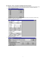
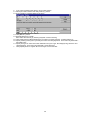
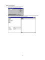
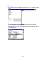
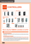
YAMAHA ROBOT CONTROLLER
SUPPORTING SOFTWARE
RCX series
VIP windows
User’s Manual
ENGLISH
E
E64-V-Ver. 1.7.0
Contents:
[1] Installation Guide
[2] Backup current data from robot controller
[3] Restore previously saved data to robot controller
[4] Operate robot controller and robots directly
[5] Modify robot controller data directly
[6] Modify various data as file on your computer
This document contains operation guide and supplementary information of VIP Windows. Be sure to read this
document before using this software.
Microsoft, Windows and Windows NT are trademarks of Microsoft Corporation. All other company and product
names mentioned are trademarks or registered trademarks of their respective owners.
22 JUL 2008
v1.7.0
1
[1] Installation Guide
Precautions
(*) As a rule, separate software sets should be purchased for each computer.
(*) This software, help and manual may not be used or reproduced in part or in their entirety without
permission.
(*) Responsibility is not accepted for any situations that may occur as a result of using this software, help or
manual.
(*) The specifications of this software, and information contained in manual and help, may be updated
without notice.
(*) The contents of this product are considered to be fully adequate and satisfactory. Should the user have
any questions or concerns, however, about this software or information contained in help and manual,
please contact your agent.
(*) Prepare to enter emergency stop input for safe when moves any axis by using automatic operation, step
operation, manual movement and trace operation.
(*) Prepare MPB/RPB programming box to setup robots, because MRC/QRC/RCX robot controllers are not
designed to use only from VIP (via RS232C).
About VIP Windows
This application is assistant software for MRC/QRC/RCX robot controller and robots. This application can be
used in the following ways:
(*) Backup current data from robot controller.
(*) Restore previously saved data to robot controller.
(*) Operate robot controller and robots directly.
(*) Modify robot controller data directly.
(*) Modify various data as file on your computer.
[A type of robot controller]
2 axes robot controller:
RCX22x
4 axes robot controller:
QRC, QRCA, QRCH, QRCH-E, QRCX
RCX40, RCX14x, RCX240
8 axes robot controller:
MRC, MRCA, MRCH, MRCH-E, MRCX
2
Package contents
[Setup disk]
CD-ROM
[Serial communication cable (Option)]
9 pins – 25 pins (for IBM-PC/AT or compatibles)
P/N: KR7-M538F-100 (for POPCOM/VIP/CUP)
Memo
(*) Prepare a 25 pins (Socket) - 9 pins (Plug) straight serial conversion adapter (P/N: KAX-M657E-010)
for RCX robot controller.
Prease refer below wiring diagram when using standard serial conversion adapter that is on the
market.
3
Required system environment
[Personal Computer]
PC with an 80386-processor minimum
32MB of RAM minimum
2MB of available hard-disk space minimum
CD-ROM drive x4 speed or more
Serial communication port
(*) USB-Serial adapter that can through any control code and manage XON/XOFF flow control can be
used.
[Operation Software]
Microsoft Windows 95, NT 4.0 or later operating system
[Robot Controller]
MRC/QRC/RCX series
(*) To operate robot from your computer, it is necessary to connect robots to robot controller and
complete to setup robot controller for robots.
Install and Un-install
Installing to hard disk on your computer is necessary for operating VIP Windows. If previous version of VIP
Windows was installed on your computer, please remove it before installing.
[Install]
1. Insert disk into the CD-ROM drive. The setup program should start automatically. If the setup program
does not start, double-click install.exe from the directory window for your CD-ROM drive.
2. Follow the instructions on your screen.
(*) From V1.6.1, the default installation folder is changed from C:\VIPWIN to C:\Program
Files\VIPWIN.
[Un-install]
1. Using Add/Remove Programs in Control Panel to remove [VIP Windows].
2. Follow the instructions on your screen.
[Un-install Manually]
1. Delete folder (C:\Program Files\VIPWIN) where VIP Windows was installed.
2. Delete configuration settings file Vipwin.ini file in the Windows folder.
3. Click [Taskbar and Start Menu] under [Settings] on [Start] menu.
4. Click [Advanced] tab in [Taskbar and Start Menu Properties] dialog box, then click [Advanced...]
button in [Start menu] group.
5. Expand [Programs] and delete [VIP Windows] folder.
4
Directory structure
When setup was completed, files are installed in the specified folder.
VIPWIN.EXE
CHECKQRC.DLL
CHECKRCX.DLL
CHECK9XX.DLL
CHECK240.DLL
VIPWIN.HLP
README.TXT
UPDATE.TXT
Start and Exit
[Start]
1. Click [VIPWIN] item in [VIP Windows] under [Programs] on [Start] menu.
2. [Select] dialog box of VIP windows is shown.
3.
Click [Cancel] button to open an empty [Main] window.
(*) If VIP needs too many time to startup, please check "Run in separate memory space" in
advanced properties of the shortcut for Windows 2000/XP.
[Exit]
1. Click [Exit] command in [File] menu to quit the application. Or, double click system menu box in [Main]
window.
2. When unsaved data is existing in [File Editor] window, a message box which suggest saving data to
file is shown.
3. When [Robot Operate] window is opened with automatic operation, a message box which suggest to
stop running is shown.
5
[2] Backup current data from robot controller
There are two methods to backup robot controller data listed below.
(*) Use System - Save command in [Robot Operate] window.
(*) Use [Download] command in empty [File Editor] window.
6
Use System - Save command in [Robot Operate] window
1.
2.
Stop running in robot controller and connect serial port on your computer with robot controller by using
serial communication cable. Then, Click [Connect Robot Controller...] command in [File] menu.
[Select Port] dialog box is shown.
3.
Select serial port where a robot controller is connected and select communication conditions using
[Conditions...] button. Then click [OK] button.
[Robot Operate] window is shown.
4.
Click [System...] button.
[System - Information] dialog box is shown.
Click [Save...] button.
7
5.
[Warning] message box is shown.
6.
Click [OK] button.
[Save As] dialog box is shown.
7.
8.
9.
Enter a new filename (Ex: rcx40.all) and click [OK] button.
[Communicating...] dialog box is shown while saving data specified by file extension and write them to
the specified file.
[OK] message box is shown if completed.
Click [OK] button.
If System (*.all) file is selected for MRC/QRC series robot controller, [Warning] message box is
shown because palette data is excluded in System (*.all) file.
Click [OK] button if palette data is used. Otherwise, click [Cansel] button. Then, [System - Information]
dialog box is shown again.Click [Close] button to return to [Robot Operate] window, and click [Close]
command in [File] menu to close [Robot Operate] window.
8
10. [Save As] dialog box that is initialized with same file name as System (*.all) file and extension is
changed for palette data is shown.
Click [OK] button.
11. [Communicating...] dialog box is shown while saving data specified by file extension and write them to
the specified file.
12. [OK] message box is shown if completed.
Click [OK] button.
13. [System - Information] dialog box is shown again.Then, click [Close] button to return to [Robot Operate]
window, and click [Close] command in [File] menu to close [Robot Operate] window.
9
Use [Download] command in empty [File Editor] window
1.
2.
Stop running in robot controller and connect serial port on your computer with robot controller by using
serial communication cable. Then, Click [Connect Robot Controller...] command in [File] menu.
[Select Port] dialog box is shown.
3.
Select serial port where a robot controller is connected and select communication conditions using
[Conditions...] button. Then click [OK] button.
[Robot Operate] window is shown.
4.
Click [New...] command in [File] menu.
[Select Robot Controller Type] dialog box is shown.
Select type of robot controller.
10
5.
[Select File Type] dialog box is shown.
6.
Select System (*.all) and click [OK] button.
[Input Program name] dialog box is shown.
7.
Click [Cancel] button.
An empty [File Editor] window is shown.
Click [Download...] command in [Edit] menu.
11
8.
[Select Port - Download] dialog box is shown.
9.
A list of serial port connected to robot controllers is shown. Select a port to backup data and click [OK]
button.
[Select Data - Download] dialog box is shown.
A list of data contained in the specified robot controller is shown. Select data to backup to [File Editor]
window and click [OK] button.
10. [Communicating...] dialog box is shown while saving data specified by file extension. Received data to
[File Editor] window from robot controller are appended or over-written if existed.
11. [OK] message box is shown if completed.
Click [OK] button to return to [File Editor] window .
12. Then, click [Save As…] command in [File] menu.
13. [Save As] dialog box is shown.
Enter a new filename (Ex: rcx40.all) and click [OK] button. Entire data in [File Edit] window is saved as a
file and a caption of [File Editor] window is changed to specified filename.
12
14. Click [Close] command in [File] menu to close [File Editor] window. Then returns to [Robot Operate]
window. Normally, click [Close] command in [File] menu to close [Robot Operate] window.
15. If palette data, which is excluded in System (*.all) file, is used on MRC/QRC series robot
controller, click [System...] button on [Robot Operate] window. [System - Information] dialog box is
shown.
Click [Save...] button.
16. [Warning] message box is shown.
Click [OK] button.
17. [Save As] dialog box is shown.
Enter a new filename (Ex: qrcx.plt) and click [OK] button.
18. [Communicating...] dialog box is shown while saving data specified by file extension and write them to
the specified file.
19. [OK] message box is shown if completed.
Click [OK] button.
20. [System - Information] dialog box is shown again. Then, click [Close] button to return to [Robot Operate]
window, and click [Close] command in [File] menu to close [Robot Operate] window.
13
[3] Restore previously saved data to robot controller
There are two methods to restore robot controller data listed below.
(*) Use System - Load command in [Robot Operate] window.
(*) Use [Upload] command in [File Editor] window.
14
Use System - Load command in [Robot Operate] window
1.
2.
Stop running in robot controller and connect serial port on your computer with robot controller by using
serial communication cable. Then, Click [Connect Robot Controller...] command in [File] menu.
[Select Port] dialog box is shown.
3.
Select serial port where a robot controller is connected and select communication conditions using
[Conditions...] button. Then click [OK] button.
[Robot Operate] window is shown.
4.
Click [System...] button.
[System - Information] dialog box is shown.
Click [Load...] button.
15
5.
[Warning] message box is shown.
6.
Click [OK] button.
[Open] dialog box is shown.
7.
8.
9.
Select a filename (Ex: rcx40.all) and click [OK] button.
[Communicating...] dialog box is shown while restoring data to robot controller from previously saved file
in your computer. Transmitted data to robot controller are appended or over-written if existed.
[OK] message box is shown if completed.
Click [OK] button.
If System (*.all) file is selected for MRC/QRC series robot controller, [Warning] message box is
shown because palette data is excluded in System (*.all) file.
Click [OK] button if palette data is used. Otherwise, click [Cansel] button. Then, [System - Information]
dialog box is shown again.Click [Close] button to return to [Robot Operate] window, and click [Close]
command in [File] menu to close [Robot Operate] window.
16
10. [Open] dialog box that is initialized with same file name as System (*.all) file and extension is changed
for palette data is shown.
Click [OK] button.
11. [Communicating...] dialog box is shown while restoring data to robot controller from previously saved file
in your computer. Transmitted data to robot controller are appended or over-written if existed.
12. [OK] message box is shown if completed.
Click [OK] button.
13. [System - Information] dialog box is shown again. Then, click [Close] button to return to [Robot Operate]
window, and click [Close] command in [File] menu to close [Robot Operate] window.
17
Use Upload command in [File Edit] window
1.
2.
Stop running in robot controller and connect serial port on your computer with robot controller by using
serial communication cable. Then, Click [Connect Robot Controller...] command in [File] menu.
[Select Port] dialog box is shown.
3.
Select serial port where a robot controller is connected and select communication conditions using
[Conditions...] button. Then click [OK] button.
[Robot Operate] window is shown.
4.
Click [Open...] command in [File] menu.
[Open] dialog box is shown.
Select a filename (Ex: rcx40.all) and click [OK] button.
18
5.
[Select Robot Controller Type] dialog box is shown.
6.
Select type of robot controller.
[File Editor] window contained with previously saved data is shown.
7.
Click [Upload...] command in [Edit] menu.
[Select Port - Upload] dialog box is shown.
A list of serial port connected to robot controllers is shown. Select a port to restore data and click [OK]
button.
19
8.
[Select Data - Upload] dialog box is shown.
A list of data contained in [File Editor] window is shown. Select data to restore to the specified robot
controller and click [OK] button.
9. [Communicating...] dialog box is shown while restoring data to robot controller from previously saved
data in [File Editor] window. Transmitted data to robot controller are appended or over-written if existed.
10. [OK] message box is shown if completed.
Click [OK] button to return to [File Editor] window .
11. Click [Close] command in [File] menu to close [File Editor] window. Then returns to [Robot Operate]
window. Normally, click [Close] command in [File] menu to close [Robot Operate] window.
12. If palette data, which is excluded in System (*.all) file, is used on MRC/QRC series robot
controller, click [System...] button on [Robot Operate] window. [System - Information] dialog box is
shown.
Click [Load...] button.
13. [Warning] message box is shown.
Click [OK] button.
20
14. [Open] dialog box is shown.
Select a filename (Ex: qrcx.plt) and click [OK] button.
15. [Communicating...] dialog box is shown while restoring data to robot controller from previously saved file
in your computer. Transmitted data to robot controller are appended or over-written if existed.
16. [OK] message box is shown if completed.
Click [OK] button.
17. [System - Information] dialog box is shown again. Then, click [Close] button to return to [Robot Operate]
window, and click [Close] command in [File] menu to close [Robot Operate] window.
21
[4] Operate robot controller and robots directly
To operate or observe status of robots connected to robot controller can be used. Prepare to enter emergency
stop input when executing automatic operation, step operation, manual movement and trace operation.
(*) Connect a robot controller
(*) Return to the origin position
(*) Move various axes manually
(*) Start automatic operation
(*) Initialize robot controller data
22
Connect a robot controller
[Robot Operate] window is needed to operate or observe status of robots connected to robot controller.
1. Stop running in robot controller and connect serial port on your computer with robot controller by using
serial communication cable. Then, Click [Connect Robot Controller...] command in [File] menu.
2. [Select Port] dialog box is shown.
3.
Select serial port where a robot controller is connected and select communication conditions using
[Conditions...] button. Then click [OK] button.
(*) If an error message box with "E0006: Receive timeout" is shown, some of communication
conditions are mismatched between robot controller and your computer. Please confirm
communication conditions in robot controller using MPB [System] – [CMU] command.
[Robot Operate] window is shown.
23
Return to the origin position
When axes controlled by incremental encoder is used, returning to the origin is needed before executing
operation after power turning on.
1. Click [Origin...] button in [Robot Operate] window.
2. [Origin] dialog box is shown.
3.
4.
5.
6.
A current origin status is shown.
Click [Motor Type: Incremental] radio button to start only axes controlled by incremental encoder return
to the origin.
[Moving...] dialog box is shown.
Click [Go!] button to start moving. [Go!] button changes to [Stop !] button while moving to stop axes.
After returning to the origin, [OK] message box is shown. Click [OK] button to return to [Origin] dialog
box.
An origin status and machine references are updated.
Click [Close] button to return to [Robot Operate] window.
24
Move various axes manually
1.
2.
Click [Manual...] button in [Robot Operate] window.
[Manual] dialog box is shown.
A current robot position with specified group, unit, shift coordinate and hand definition, and also manual
movement speed.
3. Click [DIO...] button to monitor or operate robot I/O.
3-1. [DIO] dialog box is shown.
(*) Each signal box shows robot I/O name automatically when mouse moves on box. A signal box
which background colored gray shows current status. A signal box which background colored white
shows current status and toggle status.
(*) Click [Update] button to reload robot I/O status.
(*) Click [Reset] button to clear all of the robot I/O outputs which can be operated.
25
4. Click [Utility...] button to release emergency status or change servo status.
4-1. A message box which suggest to release emergency stop status is shown when robot controller is in
emergency stop status.
Click [OK] button.
4-2. [Utility] dialog box is shown.
(*) Click check box in [Motor] group to change servo motor status. For axes provided with a brake,
brake can be canceled with [Free] check box. Since especially heavy vertical movement axes, use
caution to prevent axis from falling due to brake cancellation procedure.
(*) Click check box in [Main Gr. Arm Type] or [Sub Gr. Arm Type] group to change arm shape to
execute movement command. When using scara type robot with millimeter unit, robot arm moves
toward cartesian coordinate system which was already set by standard coordinate setting.
(*) Click check box in [Sequence] group to change sequencer status.
(*) Click combo box in [Access Level] group to change security level to modify data in robot controller.
(*) Click combo box in [Execute Level] group to change execution level to execute program in robot
controller.
(*) Click [check box in [Language] group to change language which is used to response communication
message from robot controller and also display in MPB.
4-3. Click [Close] button to return to [Manual] dialog box.
5. Use [-] or [+] button to move axis directly as Teaching-Playback. Click button to move inching distance.
Hold down button to move smoothly. When button is released, axis stops immediately.
6. Press EMERGENCY button on top panel of robot controller or MPB to move axis directly by hand as
Direct-Teaching. Click [POS] button to update robot position.
(*) Click [Utility...] button to release emergency stop status.
26
7. Click [Position Trace...] button to move axis where specified by value.
7-1. [Position Trace] dialog box is shown.
Specify movement condition and position, then click [Go!...] button.
(*) Click [Utility...] button to specify arm shape to execute movement command.
7-2. [Moving...] dialog box is shown.
Click [Go!] button to start moving. [Go!] button changes to [Stop !] button while moving to stop axes.
7-3. Click [Close] button to return to [Manual] dialog box.
8. Click [Point Trace...] button to move axis where specified by point number.
8-1. [Point Trace] dialog box is shown.
Specify movement condition and point number, then click [Go!...] button.
(*) Click [Utility...] button to specify arm shape to execute movement command.
8-2. [Moving...] dialog box is shown.
Click [Go!] button to start moving. [Go!] button changes to [Stop !] button while moving to stop axes.
8-3. Click [Close] button to return to [Manual] dialog box.
27
9.
Click [Interpolate Trace...] button to move axis where specified by point number with linear or circular
interpolation.
9-1. [Interpolate Trace] dialog box is shown.
Specify movement condition and position, then click [Go!...] button.
(*) Click [Utility...] button to specify arm shape to execute movement command.
9-2. [Moving...] dialog box is shown.
Click [Go!] button to start moving. [Go!] button changes to [Stop !] button while moving to stop axes.
9-3. Click [Close] button to return to [Manual] dialog box.
10. Click [Close] button to return to [Robot Operate] window.
28
Start automatic operation
1.
Click [Show Exe.Program] check box to show currently execution program steps in right side of window.
(*) A current step is background colored yellow.
(*) A breakpoint is character colored red.
(*) Press [F9] key after placing cursor position to set or clear breakpoint status.
2. Click [Exe.Program] combo box to change to a new execution program. When program was changed,
whole outputs and variables will be cleared.
3. Click [Exe.Task] combo box to change to a new task.
4. Click [Exe.Speed] combo box to enter a new robot moving speed.
5. Click [Start...] button to start automatic operation and click [Stop] button to stop automatic and step
operation.
6. Click [Reset...] button to reset operation. When program reset was executed, whole outputs and
variables will be cleared and program step will be return to top step of first executed program.
7. Click [Break...] button to refer or clear breakpoint. If break point was set, program step can be paused at
step while automatic and step operating.
8. Click [Step] button to execute current step. One program command statement of current step is
executed, and current step is moved to next line after execution. If command statement is a sub-routine
or sub-procedure, it is executed in top line.
9. Click [Next] button to execute current step to next step. One program command statement of current
step is executed, and current step is moved to next line after execution. If command statement is a subroutine or sub-procedure, it is executed in one batch.
10. Click [Skip] button to skip current step. One program command statement of current step is skipped
without execution, and current step is moved to next line.
29
Initialize robot controller data
Initialize various data contained in robot controller.
1. Click [System...] button in [Robot Operate] window.
2. [System - Information] dialog box is shown.
3.
4.
5.
6.
Click [Initialize...] button.
[Initialize] dialog box is shown.
Check check box for each data to be initialized and click [OK] button. An initialized data cannot be
recover.
Click [Close] button to return to [System - Information] window.
Click [Close] button to return to [Robot Operate] window.
30
[5] Modify robot controller data directly
To create and edit program, point, parameter, shift and/or hand data directory used with robot controller.
(Online Editing)
(*) How to use [Online Edit] dialog box
(*) Add a new program
(*) Modify program step
(*) Modify point data
(*) Modify parameter data
(*) Modify shift coordinate data
(*) Modify hand definition data
(*) Modify palette data
31
How to use [Online Edit] dialog box
1.
2.
Click [Online Edit...] button in [Robot Operate] window.
[Online Edit] dialog box is shown.
(*) List of entire data which contains in robot controller is displayed in [Directory] list box. Function
buttons are enabled or disabled by selected item in list box.
Append
Modify
Copy
Delete
Rename
Attrib
Program
O
X
X
X
X
X
Program name
X
O
O
O
O
O
Point
X
O
X
X
X
X
Point Comment
X
O
X
X
X
X
Parameter
X
O
X
X
X
X
Shift
X
O
X
X
X
X
Hand
X
O
X
X
X
X
Palette
X
X
X
X
X
X
Palette number
X
O
X
O
X
X
(*) A number of programs and maximum numbers of programs are shown in [Programs] edit box.
(*) Sum of program and point bytes which were currently used and program object bytes which was
compiled are shown in [Memory] edit box.
(*) Sum of program and point bytes exclude program name, end of line code counts as 1 and one point
data count as 28 bytes for RCX or 25 bytes for MRC/QRC.
32
Add a new program
1.
2.
Select [Program] item and click [Append...] button in [Online Edit] dialog box.
[Input Program name] dialog box is shown.
3.
Enter a new program name and click [OK] button.
An empty [Online Edit - Program] dialog box is shown.
(*) A specified program name is shown in caption (top of dialog box).
(*) Already registered program steps are shown in list box. Function buttons are enabled or disabled by
selected item in list box.
Append
Modify
Delete
Data line
O
O
O
Bottom line
O
X
X
(*) A current selected step and a number of steps exclude bottom line is shown in [Steps] edit box.
4. In the case of adding a new program step.
4-1. Check [Function] check box and click [Append...] button.
4-2. [Function bar] dialog box is shown.
Select opecode in list box and click [O] button.
33
4-3. [Function bar - Option] dialog box for the specified opecode is shown. (Ex: MOVE)
Enter options for the specified opecode and click [OK] button.
4-4. A new program step is added to [Online Edit - Program] dialog box.
5. In the case of modifying program step.
5-1. Select program step in list box and click [Modify...] button.
5-2. [Line Edit] dialog box is shown.
Edit specified program step and click [O] button.
6. In the case of removing program step.
6-1. Select program step in list box and click [Delete...] button.
7. Click [Update] button to register all of the changes to robot controller.
34
Modify program step
1.
2.
Select [Program name] item and click [Modify...] button in [Online Edit] dialog box.
[Online Edit - Program] dialog box is shown.
(*) A specified program name is shown in caption (top of dialog box).
(*) Already registered program steps are shown in list box. Function buttons are enabled or disabled by
selected item in list box.
Append
Modify
Delete
Data line
O
O
O
Bottom line
O
X
(*) A current selected step and a number of steps exclude bottom line is shown in [Steps] edit box.
3. In the case of adding a new program step.
3-1. Check [Function] check box and click [Append...] button.
3-2. [Function bar] dialog box is shown.
Select opecode in list box and click [O] button.
3-3. [Function bar - Option] dialog box for the specified opecode is shown. (Ex: MOVE)
Enter options for the specified opecode and click [OK] button.
35
4. In the case of modifying program step.
4-1. Select program step in list box and click [Modify...] button.
4-2. [Line Edit] dialog box is shown.
Edit specified program step and click [O] button.
5. In the case of removing program step.
5-1. Select program step in list box and click [Delete...] button.
6. Click [Update] button to register all of the changes to robot controller.
36
Modify point data
1.
2.
Select [Point] item and click [Modify...] button in [Online Edit] dialog box.
[Online Edit - Point] dialog box is shown.
3. In the case of modifying point data.
3-1. Select point data in list box and click [Modify...] button.
3-2. [Line Edit] dialog box is shown.
Edit specified point data and click [O] button.
4. In the case of copying range of point data.
4-1. Click [Copy...] button.
4-2. [Point Copy] dialog box is shown.
Specify source ranges where copied from and destination number where copied to, then click [OK]
button.
5. In the case of removing range of point data.
5-1. Click [Delete...] button.
5-2. [Point Delete] dialog box is shown.
Specify ranges and click [OK] button.
37
6. In the case of teaching point data by current robot position.
6-1. Select point data in list box and click [Teaching...] button.
6-2. [Point Teaching - Position] dialog box is shown.
A new point data is shown in edit box.
6-3. Click [Manual...] button.
6-4. [Manual] dialog box is shown.
Move robot axis manually by Teaching-Playback or Direct-Teaching.
6-5. Click [Close] button in [Manual] dialog box and returns to [Point Teaching - Position] dialog box.
6-6. Specify teaching axis in [Axis: x/y/z/r/a/b] check box and click [OK] button. Then returns to [Online Edit Point] dialog box.
6-7. Specify arm type for scara robot under millimeter unit in [Arm Type: None/Righty/Lefty] check box and
click [OK] button. Then returns to [Online Edit - Point] dialog box.
7. Click [Update] button to register all of the changes to robot controller.
38
Modify parameter data
1.
2.
Select [Parameter] item and click [Modify...] button in [Online Edit] dialog box.
[Online Edit - Parameter] dialog box is shown.
3. In the case of modifying parameter data.
3-1. Select parameter data in list box and click [Modify...] button.
3-2. [Line Edit] dialog box is shown.
4.
Edit specified parameter data and click [O] button.
Click [Update] button to register all of the changes to robot controller.
39
Modify shift coordinate data
1.
2.
Select [Shift] item and click [Modify...] button in [Online Edit] dialog box.
[Online Edit - Shift] dialog box is shown.
(*) Already registered shift coordinate data are shown in list box. Function buttons are enabled or
disabled by selected item in list box.
Modify
Direction
Position
S line
O
O
O
SP/SM line
O
X
X
3. In the case of modifying shift coordinate data.
3-1. Select shift coordinate data in list box and click [Modify...] button.
3-2. [Line Edit] dialog box is shown.
4.
Edit specified shift coordinate data and click [O] button.
Click [Update] button to register all of the changes to robot controller.
40
Modify hand definition data
1.
2.
Select [Hand] item and click [Modify...] button in [Online Edit] dialog box.
[Online Edit - Hand] dialog box is shown.
3. In the case of modifying hand definition data.
3-1. Select hand definition data in list box and click [Modify...] button.
3-2. [Line Edit] dialog box is shown.
4.
Edit specified hand definition data and click [O] button.
Click [Update] button to register all of the changes to robot controller.
41
Modify palette data
1.
2.
Select [Palette number] item and click [Modify...] button in [Online Edit] dialog box.
[Online Edit - Palette] dialog box is shown.
3. In the case of modifying palette data.
3-1. Select palette data in list box and click [Modify...] button.
3-2. [Line Edit] dialog box is shown.
4.
Edit specified palette data and click [O] button.
Click [Update] button to register all of the changes to robot controller.
42
[6] Modify various data as file on your computer
To create and edit program, point, parameter, shift and/or hand data as a file used with robot controller on your
computer. (Off-line Editing)
(*) Create a new file
(*) Open a previously created file
(*) Add a new program
(*) Modify program step
(*) Modify point data
(*) Modify parameter data
(*) Modify shift coordinate data
(*) Modify hand definition data
(*) Check modified data
43
Create a new file
1.
2.
Click [New...] command in [File] menu.
[Select Robot Controller Type] dialog box is shown.
2.
Select type of robot controller.
[Select File Type] dialog box is shown.
3.
Select file type and click [OK] button. (Ex: System (*.all))
[Input Program name] dialog box is shown.
4.
Click [Cancel] button.
An empty [File Editor] window is shown.
44
Open a previously created file
1.
2.
Click [Open...] command in [File] menu.
[Open] dialog box is shown.
3.
Select a filename (Ex: rch40.all) and click [OK] button.
[Select Robot Controller Type] dialog box is shown.
4.
Select type of robot controller.
[File Edit] window is shown.
45
Add a new program
1.
2.
Click [Program Create...] command in [Edit] menu.
[Input Program name] dialog box is shown.
3.
Enter a new program name and click [OK] button.
Specified program name is added in [Sheet Selector] pane window on left side of [File Editor] window
and an empty [Sheet Editor] pane window is shown on right side.
46
Modify program step
1. Click [Program name] item in list box on [Sheet Selector] pane window on left side of [File Editor] window.
2. Entire program steps are shown in [Sheet Editor] pane window is shown on right side of [File Editor]
window.
(*) Press [F1] key to show context sensitive help.
(*) Standard editing commands are prepared in [Edit] menu.
3. Click [Sheet Editor] pane window to edit program step directly by using keyboard.
4. In the case of adding a new program step, click [Sheet Editor] pane window and click [Function bar]
command in [View] menu.
4-1. [Function bar] dialog box is shown.
Select opecode in list box and click [O] button.
47
4-2. [Function bar - Option] dialog box for the specified opecode is shown. (Ex: MOVE)
Enter options for the specified opecode and click [OK] button.
4-3. A new program step is added to [Sheet Editor] pane window.
4-4. Click [Function bar] dialog box to specify new program steps.
48
Modify point data
1.
2.
Click [Point] item in list box on [Sheet Selector] pane window on left side of [File Editor] window.
Entire point data are shown in [Sheet Editor] pane window is shown on right side of [File Editor] window.
3.
(*) Press [F1] key to show context sensitive help.
(*) Standard editing commands are prepared in [Edit] menu.
Click [Sheet Editor] pane window to edit point data directly by using keyboard.
49
Modify parameter data
1.
2.
3.
Click [Parameter] item in list box on [Sheet Selector] pane window on left side of [File Editor] window.
Entire parameter data are shown in [Sheet Editor] pane window is shown on right side of [File Editor]
window.
(*) Press [F1] key to show context sensitive help.
(*) Standard editing commands are prepared in [Edit] menu.
Click [Sheet Editor] pane window to edit parameter data directly by using keyboard.
50
Modify shift coordinate data
1.
2.
3.
Click [Shift] item in list box on [Sheet Selector] pane window on left side of [File Editor] window.
Entire shift coordinate data are shown in [Sheet Editor] pane window is shown on right side of [File
Editor] window.
(*) Press [F1] key to show context sensitive help.
(*) Standard editing commands are prepared in [Edit] menu.
Click [Sheet Editor] pane window to edit shift coordinate data directly by using keyboard.
51
Modify hand definition data
1.
2.
3.
Click [Hand] item in list box on [Sheet Selector] pane window on left side of [File Editor] window.
Entire hand definition data are shown in [Sheet Editor] pane window is shown on right side of [File
Editor] window.
(*) Press [F1] key to show context sensitive help.
(*) Standard editing commands are prepared in [Edit] menu.
Click [Sheet Editor] pane window to edit hand definition data directly by using keyboard.
52
Check modified data
1.
2.
Click [Data Check...] command in [Edit] menu to start checking entire data in [Sheet Editor] pane window
which is shown on right side.
[Output] window is shown.
3.
If an error was detected, a window is shown below.
3-1. Press [F1] key to show error message help for cursor blinking line.
3-2. Press [Enter] key or click [Jump] command in [Edit] menu to jump error occurrence line.
53