1
•
•
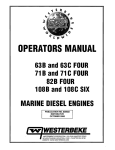
OPERATORS MANUAL
Unlvarsal
MARINE DIESEL ENGINES
M3·20A M3·20B M·25XPA M·25XPB
M·35A M·35B
PUBUCATION 200494
1ST EDITION I APRIL 1997
I~
WESTERBEKE CORPORATION· AVON INDUSTRIAL PARK
AVON, MA 02322 • TEL: (508) 588-noo • FAX: (508) 559-9323
"'~~~
M~mMr NaJ;olllll Marin~ Manufocturrrs Association
---
N MMA
OPERATORS MANUAL
Univarsal
MARINE DIESEL ENGINES
M3-20A M3-20B M-25XPA M-25XPB
M-35A M-35B
PUBLICATION 200494
1ST EDITION I APRIL 1997
I~
WESTERBEKE CORPORATION· AVON INOUSTRIAL PARK
AVON, MA 02322 • TEL: (508) 588-7700 • FAX: (508) 559-9323
....iIIr~~
NMMA Member Nalional Marine Maflujacluren;Assocullion
...,.".,..,
CALIFORNIA
PROPOSmON 65 WARNING
Diesel engine exhaust and some
of its constituents are known to
the State of California to cause
cancer, birth defects, and other
reproductive harm.
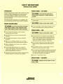
SAFETY INSTRUCTIONS
UNIVERSAL DIESEL ENGINES
INTRODUCTION
Rem! this safety manlllll carefully. Most accidents are caused
IJy failure to follow juruiJlmenJal rules and precautions.
Know when dangerous conditions erist and take the
necessary precautions to protect yourself, your personnel,
and your machinery.
The foUuwing safety instructions are in compliance with
the American Boat and Yacht Council (ABYC) staruiJlrtis.
PREVENT ELECTRIC SHOCK
A WARNING: Do nat touch AC electrical CI1IIIIIiCtions
nile engine is running, IX nen connected to shore
power. Lethal roltage is present at these connections!
• Do not operate this machinery without electrical
enclosures and covers in place.
PREVENT BURNS - HOT ENGINE
A WARNING: Do not much hat engine parts or
exhaust system components. A running engine gets
vert hat!
• Always check the engine coolant level at the coolant
recovery tank.
IA WARNING:
Steam can cause injury or death!
• In case of an engine overheat, allow the engine to cool
before touching the engine or checking the coolant.
PREVENT BURNS - ARE
IA WARNING:
Steam can cause injury or death!
• Shut off electrical power before accessing electrical
equipment.
• Prevent flash fires. Do not smoke or permit flames or
sparks to occur near the carburetor, fuel line, filter, fuel
• Use insulated mats whenever working on electrical
equipment.
• Make sure your clothing and skin are dry, not damp
(particularly shoes) when handling electrical equipment.
• Remove wristwatch and all jewelry when working on
electrical equipment.
• Do not connect utility shore power to vessel 's AC
circuits, except through a ship-to-shore double throw
transfer switch. Damage to vessel's AC generator may
result if this procedure is not followed.
• Electrical shock results from handling a charged capacitor.
Discharge capacitor by shorting terminals together.
pump, or other potential sources of spilled fuel or fuel
vapors. Use a suitable container to catch all fuel when
removing the fuel line, carburetor, or fuel filters.
• Do not operate with the Coast Guard Approved flame
arrester removed. Backfire can cause severe injury or
death.
• Do not operate with the air cieaner/siJencer removed.
Backfire can cause severe injury or death.
• Do not smoke or permit flames or sparks to occur near the
fuel system. Keep the compartment and the engine/gener-
ator clean and free of debris to minimize the chances of
fire. Wipe up all spilled fuel and engine oil.
• Be aware -
diesel fuel will bum.
PREVENT BURNS - EXPlOSION
A WARNING: Explosions from fuel raptllS can cause
injury Dr death!
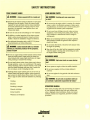
SAFETY INSTRUCTIONS
PREVENT BURNS - EXPLOSION (continued)
BATTERY EXPLOSION
A WARNING: Battery explasian can cause injury
• Follow re-fueling safety instructions. Keep the vessel 's
hatches closed when fueling. Open and ventilate cabin
after fueling. Check below for fumes/vapor before running
the blower. Run the blower for four minutes before starting your engine.
I
· ardeath!
• Do not smoke or allow an open flame near the battery
being serviced. Lead acid batteries emit hydrogen, a
highly explosive gas, which can be ignited by electrical
arcing or by lit tobacco products. Shut off all electrical
• All fuel vapor.; are highly explosive. Use extreme care when
handling and storing fuels. Store fuel in a well-ventilated
area away from spark-producing equipment and out of the
reach of children.
equipment in the vicinity to prevent electrical arcing during
seJVicing.
• Do not fill the fuel tank(s) while the engine is running.
• Never connect the negative (-) battery cable to the positive (+) connection terminal of the starter solenoid. Do not
test the battery condition by shorting the terminals
together. Sparks could ignite battery gases or fuel vapor.;.
• Shut off the fuel service valve at the engine when servicing
the fuel system. Take care in catching any fuel that might
spill. DO NOT allow any smoking, open flames, or other
sources of fire near the fuel system or engine when servicing.
Ensure proper ventilation exists when servicing the fuel
Ventilate any compartment containing baneries to prevent
accumulation of explosive gases. To avoid sparks, do not
disturb the battery charger connections while the battery is
being cbarged.
system.
• Do not alter or modify the fuel system.
• Avoid contacting the terminals with tools, etc., to prevent
bums or sparks that could cause an explosion. Remove
• Be sure all fuel supplies have a positive shutoff valve.
wristwatch, rings, and any other jewelry before handling
the battery.
• Be certain fuel line firtings are adequately tightened and
free of leaks.
• Always tum the battery cbarger off before disconnecting
the battery connections. Remove the negative lead first
and reconnect it last when disconnecting the battery.
• Make sure a fire extinguisher is installed nearby and is
properly maintained. Be familiar with its proper use.
Extinguisher.; rated ABC by the NFPA are appropriate
for all applications encountered in this environmenL
BATTERY ACID
ACCIDENTAL STARTING
AWARNING:
I
A WARNING: Sulphuric acid in batteries can cause
Accidetrtal slaTting can cause iajuty
sereTe iajury /If death!
· ar death!
• When servicing the battery or checking the electrolyte
• Disconnect the battery cables before servicing the engine!
level, wear rubber gloves, a rubber apron, and eye protec-
generator. Remove the negative lead first and reconnect
tion. Batteries contain sulfuric acid which is destructive. If
it comes in contact with your skin, wash it off at once
it last.
with water. Acid may splash on tbe skin or into the eyes
inadvertently when removing electrolyte caps.
• Make certain all personnel are clear of the engine before
starting.
• Make certain all covers, guards, and hatches are reinstalled before starting the engine.
ii
SAFETY INSTRUCTIONS
TOXIC EXHAUST GASES
AVOID MOVING PARTS
IA WARNING:
AWARNING:
I· or
Cal'llon monoxide (CO) is a deadly gas!
Rotating parts can cause injury
death!
• Ensure that the exhaust system is adequate to expel gases
discharged from the engine. Check the exhaust system
regularly for leaks and make sure the exhaust manifolds
are securely attached and no warping exists. Pay close
• Do not service the engine while it is running. If a situation
arises in which it is absolutely necessary to make operating adjustments, use extreme care to avoid touching moving parts and hot exhaust system compone~ts.
attention to the manifold, water injection elbow, and
exhaust pipe nipple.
• Do not wear loose clothing or jewelry when servicing
• Be sure the unit and its surroundings are well ventilated.
equipment; avoid wearing loose jackets, shirts, sleeves,
rings, neckJaces or bracelets that could be caught in
• In addition to routine inspection of the exhaust system,
install a carbon monoxide detector. Consult your boat
moving parts.
builder or dealer for installation of approved detectors.
• Make sure all attaching hardware is properly tightened.
Keep protective shields and guards in their respective
places at all times.
• For additional information refer to ABYC T-22 (educational information on Carbon Monoxide).
A WARNING: Carbon monoxide (CO) is an invisible
• Do not check fluid levels or the drive belt's tension while
the engine is operating.
odOfless gas_ Inhalation produces flu-like symptDms,
nausea Of death!
• Stay clear of the drive shaft and the transmission coupling
when the engine is running; hair and clothing can easily
be caught in these rotating parts.
• Do not use copper tubing in diesel exhaust systems. Diesel
HAZARDOUS NOISE
fumes can rapidly destroy copper tubing in exhaust systems. Exhaust sulfur causes rapid deterioration of copper
tubing resulting in exhaust/water leakage.
A WARNING: High noise /ere/s can cause hearing
I
• Do not install exhaust outlet where exhaust can be drawn
through portholes, vents, or air conditioners. If the engine
exhaust discharge outlet is near the waterline, water could
· loss!
• Never operate an engine without its muffler installed.
enter tbe exhaust discharge outlet and close or restrict the
flow of exhaust. Avoid overloading the craft.
• Do not run an engine with the air intake (silencer)
removed.
• Although diesel engine exhaust gases are not as toxic as
exhaust fumes from gasoline engines, carbon monoxide
gas is present in diesel exhaust fumes. Some of the symptoms or signs of carbon monoxide inhalation or poisoning
• Do not run engines for long periods with their enclosures
OpeD.
A
are:
WARNING: Do not work on machinery when you
are mentally or physically incapacitated by fatigue!
Vomiting
Dizziness
Throbbing in temples
OPERATORS MANUAL
Muscular twitching
Many of the preceding safety tips and warnings are repeated
in your Operators Manual along with other cautions and
notes to highlight critical information. Read your manual
carefully, maintain your equipment, and follow all safety
procedures.
Intense headache
Weakness and sleepiness
iii
SAFETY INSTRUCTIONS
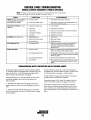
RECOMMENDED INSTALlATION CODES AND SAfETY STANDARDS
ENGINE INSTALlATIONS
Preparations to install an engine should begin with a thor-
ough examination of the American Boat and Yacht Council 's
(ABYC) standards. These standards are a combination of
sources including the USCG and the NFPA.
Sections of the ABYC standards of particular interest are:
H-2 Ventilation
P-l Exhaust systems
P-4 Inboard engines
E-9 DC Electrical systems
All installations must comply with the Federal Code of
Regulations (FCR).
ABYC, NFPA AND USCG PUBUCATIONS FOR
INSTAWNG DIESEL ENGINES
Read the following ABYC. NFPA and USCG publications
for safety codes and standards. Follow their recommendations when installing your UNIVERSAL engine
ABYC (American Boat and Yacht Council)
" Safety Standards for Small Craft"
Order From:
ABYC
15 East 26th Street
New York, NY 10010
NFPA (National Fire Protection Association)
"Fire Protection Standard for Motor Craft"
Order From:
NFPA
1 Banerymarch Park
P.O. Box 9101
Quincy. MA 02269-9101
USCG (United States Coast Guard)
"USCG 33CFR183"
Order From:
U.S. Government Printing Office
Washington, D. C. 20404
TABLE OF CONTENTS
Introduction .......................................................................2
Warranty Procedures .. __ ............................................ __ .. 2
Typical Customer Identification Card .......................... 2
Product Software .......... _........... _........... _....................... 2
Notes, Cautions and Warnings ..................................... 2
Serial Number Location ............................................... 3
Understanding the Diesel Engine ................................. 3
Ordering Parts .............................................................. 3
Description ............
. ...................................... 20
Alternator Troubleshooting ................................. 20
Checking for Propcr Voltage .............................. .20
Engine 12 Volt DC Control Circuit ............................ 21
Drivc Belt Adjustmcnt .............................................. .21
Battery Care ............................................................... 21
Glow Plugs ................................................................ 21
Wiring Diagram .............................................................. .22
Wiring Schematic ...........................................................23
Engine Adjustments ...................................................... .24
Spares and Accessories ................................................ 3
Protecting Your Investment .......................................... 3
Admiral Control Panel .....................................................4
Captain Control Panel .....................................................5
Diesel Fuel, Engine Dil and Engine Coolant ............... 6
Throttle and Stop Assembly ....................................... 24
Valve Clearance .......................................................... 24
Water Heater Connections ............................................25
Water Heater Installations .......................................... 25
Engine Troubleshooting .................................................26
Diesel Fuel ................................................................... 6
Care of the Fuel Supply ........................................ 6
Engine Oil ............................................................. 6
Engine Coolant ............................................................. 6
Coolant and Recovery Tank ......................................... 6
Control Panel Troubleshooting ....................................28
Manual Starter Disconnect (Toggle Switches) .......... 28
Troubleshooting Water Temperature and
Oil Pressure Gauges ................................................... 28
Tachometer Troubleshooting ........................................ 29
Tachometer/Hourmeter ............................................... 29
Hourmeter Inoperative ........................................ 29
Tachometer Inoperative ...................................... .29
Tachometer Sticking ........................................... 29
Calibration .......................................................... 29
HBW Transmission ..........................................................30
Initial Operation ......................................................... 30
Gearbox Operation ..................................................... 30
When Under Sailor Being Towed ............................. 30
Locking the Prop ....................................................... .30
Control Cables ........................................................... .30
Maintenance ............................................................... 31
Transmission Fluid .............................................. 31
Capacity .............................................................. 31
Fluid Change ...................................................... .31
Checking the Bowdin Cable or Rod Linkage ..... 31
Propeller Shaft Alignment ................................ .31
Lay-Up/Winterize ............................................... .31
Lay-Up and Recommissioning ......................................32
Lay-Up ....................................................................... 32
Propeller Shaft Coupling ........................................... .32
Fresh Water Cooling System ...................................... 32
Lubrication System ................................................... .32
Fuel System ................................................................ 32
Raw Water Circuit ..................................................... .32
Intake Manifold ......................................................... .32
Starter Motor .............................................................. 33
Cylinder Lubrication ................................................. 33
Transmission .............................................................. 33
Spares ......................................................................... 33
Batteries ...................................................................... 33
Recommissioning ....................................................... 33
Specifications .................................................................34
Parts Identification ........................................................36
Preparations for Initial Start-Up ................................... 7
Prestart Inspection ........................................................ 7
StartingJStopping Procedure ..........................................8
Starting Procedure ........................................................ 8
Preheat .......................................................................... 8
Start .............................................................................. 8
Starting Under Cold Conditions ................................... 8
Stopping Procedure ...................................................... 8
Break-In Procedure ..........................................................9
The First 50 Hours ....................................................... 9
The Daily Routine ........................................................... 10
Check List .................................................................. 10
Start Your Engine ....................................................... I 0
Maintenance Schedule .................................................. 11
Engine Cooling Circuit... ................................................ 13
Description ................................................................. 13
To Refill With Coolan!... ..................................... 13
Thermostat .................................................................. 14
To Replace the Thermostat ................................. 14
Raw Water Cooling Circuit ........................................ 14
Raw Water Pump ................................................ 14
Changing the Raw Water Impeller. ..................... 15
Heat Exchanger ................................................... 15
Zinc Anode .......................................................... 15
Engine Oil Change ..........................................................16
Drain the Sump .......................................................... 16
Replacing the Oil Filter.. ..................................... 16
Refill the Oil Sump ............................................. 16
Remote Oil Filter ............................................................ 17
Installation .................................................................. 17
Fuel System ....................................................................18
Fuel Filters ................................................................ 18
Fuel Water Separator .................................................. 18
Fuel Additivcs ............................................................ 19
Spares ......................................................................... 19
Primary (Blecding/The Fuel System) ........................ 19
Air Cleaner/Silencer ............................................ 19
Metric Conversions......................................
.......... 37
Standard Hardware Torques .......................
.......... 3R
Spare Parts ....................................................................39
DC Electrical System .................................................20
1
INTRODUCTION
PRODUCT SOFTWARE
These new high perfonnance UNIVERSAL marine diesel
engines are a product of UNIVERSAL/WESTERBEKE's
design technology and their combined years of experience
manufacturing quality marine engines. We take great pride in
the superior durability and dependable performance of our
marine engines. Thank you for selecting UNIVERSAL.
Product software (tech data, parts lists, manuals, hrochurcs and
catalogs) provided from sources other than liNTVERSAL arc not
within UNIVERSAL'S CONTROL
UNIVERSAL CANNOT BE RESPONSIBLE FOR THE
CONTENT OF SUCH SOFTWARE, MAKES NO WARRANTIES OR REPRESENTATIONS WlTH RESPECT
THERETO, INCLUDING ACCURACY, TIMELINESS OR
COMPLETENESS THEREOF AND WILL IN NO EVENT
BE LIABLE FOR ANY TYPE OF DAMAGE OR INJURY
INCURRED IN CONNECTION WITH OR ARISING OUT
OF THE FURNISHING OR USE OF SUCH SOFTWARE.
In order to get the full use and benefit from your engine, it is
important that you operate and maintain it correctly. This
manual is designed to help you do this. Please read this
manual carefully and observe all the safety precautions
throughout An extensive network of UNIVERSAL!
\VESTERBEKE distributors. dealers and service centers are
available worldwide. Should your engine require servicing,
contact your nearest dealer for assistance.
UNIVERSAL customers should also keep in mind the time
span between printings of UNIVERSAL product software
and the unavoidable existence of earlier UNIVERSAL
manuals. In summation, product software provided with
UNNERSAL products, whether from UNIVERSAL or other
suppliers, must not and cannot be relied upon exclusively as
the definitive authority on the respective product. It not only
makes good sense but is imperative that appropriate representatives of UNNERSAL or the supplier in question be consulted to detennine the accuracy and currentness of the
product software being consulted by the customer.
This is your operators manual. A Parts Catalog is also
provided and a Technical Manual is available from your
UNIVERSAL dealer. Also, if you are planning to instal! this
equipment, contact your UNIVERSAL dealer for
UNIVERSAL'S installation manual.
WARRANTY PROCEDURES
Your UNIVERSAL Warranty is included in a separate folder.
If you have not received a customer identification card registering your warranty 60 days after submitting the warranty
registration fonn, please contact the factory in writing with
model information, including the unit's serial number and
commission date.
NOTES, CAUTIONS AND WARNINGS
As this manual takes you through the operating procedures,
maintenance schedules, and troubleshooting of your marine
engine, critical information will be highlighted by NOTES.
CAUTIONS, and WARNINGS. An explanation follows:
NOTE: An operating procedure essential to note.
Customer Identification
A CAUTION: Procedures, which if not strictly
UNIVERSAL OWNER
MAIN STREET
HOMETOWN, USA
observed, can result in the damage or destruction of
your engine,
Model M-35B
AWARNING: Procedures, which if not properly followed, can result in personal injury or loss of life,
Sec #XXXX-D704
Expires 7/20/97
TYPICAL CUSTOMER IDENTIFICATION CARD
The UNIVERSAL serial number is an alphanumeric
number that can assist in determining the date of manufacture
of your UNIVERSAL engine. The first character after the
dash indicates the decade [A=1960s, B=1970s, C=1980s,
D:::::! 990s, etc.:.], the second character represents the year in
the decade, and the fourth and fifth numbers represent the
month of manufacture.
2
INTRODUCTION
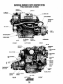
SERIAL NUMBER LOCATION
ORDERING PARTS
An identification nameplate that displays the engine model
number and engine serial number is mounted on the side of
the engine's manifold. Take the time to enter this information
on the blank decal provided below. This will provide a quick
reference when seeking technical information and/or ordering
Whenever replacement parts are needed, always provide the
engine model number and engine serial number they
appear on the silver and black identification nameplate
located on the manifold. You must provide us with this information so we can identify your engine. In addition, include a
complete part description and part number for each part
needed (see the separately furnished Parts Catalog). Also
insist upon UNIVERSAUWESTERBEKE packaged parts
because will fit or generic parts are frequently not made to
the same specifications as original equipment.
a,
parts.
•
MODE'-
SPEC
SER.NO.
SPARES AND ACCESSORIES.
•
Certain spares will be needed to support and maintain
your UNIVERSAL marine engine. Your UNIVERSAU
WESTERBEKE dealer will assist you in preparing an on
board inventory of spare parts. See the UNIVERSAL SPARE
PARTS page in this manual for a suggested list.
UNDERSTANDING THE DIESEL ENGINE
The diesel engine closely resembles the gasoline engine,
since the mechanism is essentially the same. The cylinders
are arranged above a closed crankcase; the crankshaft is of
the same general type as that of a gasoline engine, and the
diesel engine has the same types of valves, camshaft, pistons,
connecting rods and lubricating system.
PROTECTING YOUR INVESTMENT
Care at the factory during assembly and thorough testing
have resulted in a UNIVERSAL diesel engine capable of
many thousands of hours of dependable service. However the
manufacturer cannot control how or where the engine is
installed in the vessel or the manner in which the unit is
operated and serviced in the field. This is up to the
buyer/owner-operator.
To a great extent, a diesel engine requires the same preventive maintenance as a gasoline engine. Most important are
proper ventilation and proper maintenance of the fuel, lubricating and cooling systems. Replacement of fuel and lubricating filter elements at the time periods specified and
frequent checking for contamination (water, sediment, etc.) in
the fuel system are essentiaL Also important is the consistent
usc of a brand of high detergent diesel lubrication oil
designed specifically for diesel engines.
NOTE: Six important sleps to ensure long engine bfe:
o Proper engine installation and alignment.
o An efficient well-designed exhaust system that includes
an anti-siphon break to prevent water from entering the
engine.
The diesel engine does differ from the gasoline engine, however, in its method of handling and firing of fuel. The carburetor and ignition systems are done away with and in their
place is a single component (the fuel injection pump) which
pcrfonns the function of both.
o Changing the engine oil and oil filters every JOO operating
hours.
o Proper maintenance of all engine components according
to the maintenance schedule in this manual.
o Use clean. tiltered diesel fucl.
o Winterize your engine according to the LAY-UP AND
RECOMMISSIONING section in this manual.
3
ADMIRAL CONTROL PANEL
UNIVERSAL offers two optional panels. Refer to the
instruction page that applies to the panel you purchased.
When the engine is shut down with the Key Switch turned
off, the water temperature gauge will continue to register the
Ja~t temperature rcading indicated hy the gauge bctllfC electncal power was turned off. The oil pressure gauge will fall
to zero when the Key Switch is turned oft·. The temperature
gauge will once again register the engine's true temperature
when electrical power is restored to the gauge.
ADMIRAL PANEL
This manually-operated control panel is equipped with a Key
Switch and RPM gauge with an ELAPSED TIME metcr
which measures the engine's running time in hours and in
1110 hours. The panel also includes a WATER TEMPERA·
TURE gauge which indicates water temperature in degrees
Fahrenheit, an OIL PRESSURE gauge which measures the
engine'5 oil pressure in pounds per square inCh, and a DC
control circuit VOLTAGE gauge which measures the system'5 voltage. All gauges are illuminated when the key
switch is turned on and remain illuminated while the engine
is in operation. The panel also contains two rubber-booted
pushbuttons, one for PREHEAT and one for START.
A se~aratc alarm buzzer with harness is supplied with every
Admiral Panel. The installer is responsible for electrically
connecting the buzzer to the four~pin connection on the
engine's electrical harness. The installer is also responsible
~or installing the buzzer in a location where it will be dry and
where it will be audible 10 the operator should it sound while
t~eengin.e is running. The buzzer will sound when the ignihon key IS turned on and should silence when the engine has
started and the engine's oil pressure rises above 15 psi.
WATER TEMPERATURE GAUGE: THIS GAUGE IS
GRADUATED IN DEGREES fAHRENHEIT AND IS
ILLUMINATED WHILE THE KEY SWITCH IS
TURNED ON. THE ENGINE'S NORMAL OPERATING
TEMPERATURE IS 170°·190° f 177°·BBOC).
OtL PRESSURE GAUGE: THIS GAUGE IS GRADUATED IN POUNDS PER SQUARE INCH (PSI) AND IS
ILLUMINATED WHILE THE KEY SWITCH IS
TURNED ON. THE ENGINE'S NORMAL OPERATING
OIL PRESSURE RANGES BETWEEN 30·60 PSI
RPM GAUGE: REGIS·
TERS REVOLUTIONS
PER MINUTE OF THE
ENGINE AND CAN BE
RECALIBRATEO FOR
ACCURACY FROM THE
REAR Of THE PANEL
HOURMETER:
REGISTERS ElAPSED
TIME, AND SHOULD BE
USED AS A GUIDE FOR
THE MAINTENANCE
SCHEDULE.
KEY SWITCH: PROVIDES
POWER ONLY TO THE
INSTRUMENT PANEL
CLUSTER.
INDICATES THE AMOUNT THE
BATTERY IS BEING CHARGED
SHOULD SHOW 13V TO 14V.
PREHEAT BUTTON: WHEN PRESSED. ENERGIZES THE
ALTERNATOR'S REGUlATOR, THE FUEL LIFT PUMP, THE
fUEL SOLENOID ON THE INJECTION PUMP, AND THE
ENGINE'S GLOW PLUGS, AND BYPASSES THE
I
OIL PRESSURE AlARM SWITCH. IN ADDITION, I
BUDON ENERGIZES THE START BUDON.
AUTOMATIC ALARM SYSTIM
HIGH WATER TEMPERATURE ALARM: AN ALARM BUZZER HAS BEEN
SUPPLIED WITH THE INSTRUMENT PANEL If THE ENGINE'S FRESH
WATER COOLANT REACHES 210° f 19BOC), THIS SWITCH WILL CLOSE
SOUNDING THE AlARM WHICH WILL EMIT A
CONTINUOUS SIGNAL.
START BUTTON: WHEN
STARTER'S SOLENOID
I
THIS BUDDN WILL NOT OPERATE ELECTRICALLY
UNLESS THE PREHEAT BUDON IS PRESSED AND HELD
ATTHE SAME TIME.
LOW OtL PRESSURE AlARM: A LOW OIL PRESSURE AlARM SWITCH
IS LOCATED OfF THE ENGINE'S OIL GALLERY THIS SWITCH MONITORS
THE ENGINE'S OIL PRESSURE. SHOULD THE ENGINEiS OIL PRESSURE
FALL TO 5·10 PSI, THE SWITCH WILL CLOSE SOUNDING THE ALARM.
IN THIS EVENT, THE AlARM WILL EMIT A PULSATING SIGNAL
4
CAPTAIN CONTROL PANEL
and one for high ENGINE COOLANT TEMPERATURE. ft
also includes an alarm buzzer for low OfL PRESSURE or
high WATER TEMPERATURE. The RPM gauge is illumi·
nated when the Key Switch is turned on and remains illuminated while the engine is in operation.
CAPTAIN PANEL
This manually~operated control panel is equipped with a Key
Switch, an RPM gauge, PREHEAT and START buttons, an
fNSTRUMENT TEST button and three indicator lamps, one
for ALTERNATOR DISCHARGE, one for low OlL PRES·
SURE,
ALARM: THE ALARM WILL SOUND If THE ENGINES OIL PRESSURE fALLS
BELOW 15 PSI. IN THIS EVENT. THE ALARM WILL EMIT A PULSATING SIG·
NAl. THE ALARM WILL ALSO SOUND If THE WATER TEMPERATURE IN THE
fRESHWATER COOLING CIRCUIT RISES TO 20S'f. IN THIS EVENT. THE ALARM
WILL EMIT A SIGNAl.
NOTE: THE ALARM WILL SOUND WHEN THE KEY SWITCH IS TURNED ON.
THIS SOUNDING IS NORMAl. ONCE THE ENGINE STARTS AND THE ENGINE'S
OIL PRESSURE REACHES 15 PSI, THE ALARM WILL SILENCE.
RPM GAUGE:
REGISTERS REVOLUTIONS PER
MINUTE Of THE ENGINE AND CAN BE
RECALIBRATED fOR ACCURACY fROM
THE REAR Of THE PANEl.
Oil PRESSURE
ALARM LIGHT
ALTERNATOR ALARM
LIGHT
TEST BUTTON: WHEN
PRESSED, TESTS THE
ALTERNATOR. THE OIL
PRESSURE. AND THE
WATER TEMPERATURE
CONTROL CIRCUITS
WHEN PRESSED. THE
ALTERNATOR. THE OIL
PRESSURE, AND THE
WATER TEMPERATURE
INDICATOR LIGHTS
ILLUMINATE IN ADDI·
TION TD SOUNDING
THE ALARM BUZZER
KEY SWITCH:
PROVIDES POWER TO
THE INSTRUMENT
PANEL CLUSTER AND
THE DC ALTERNATOR
REGULATOR TERMINAL.
WATER TEMPERATURE ALARM
LIGHT
START BUTTON: WHEN PRESSED. ENERGIZES THE
STARTER'S SOLENOID WHICH CRANKS THE ENGINE THIS
BUTTDN WILL NOT OPERATE ELECTRICALLY UNLESS THE
PREHEAT BUTTON IS PRESSED AND HELD AT THE SAME
TIME.
5
PREHEAT BUTTON: WHEN PRESSED. ENERGIZES THE fUEL
LIfT PUMP AND THE ENGINE'S GLOW PLUGS. ANa BYPASSES
THE ENGINE'S OIL PRESSURE ALARM SWITCH. IN ADDITION.
THIS BUTTON ENERGIZES THE START BUTTON
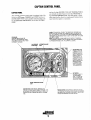
DIESEL FUEL, ENGINE OIL AND ENGINE COOLANT
DIESEL FUEL
ENGINE COOLANT
Use fuel that meets the requirements or specification of Class
2-D (ASTM), and has a cetane rating of #45 or better.
UNNERSAL recommends a mixture of 50% antifreeze and
50% distilled water. Distilled water is free from the chemicals that can corrode internal engine surfaces.
Care Of The Fuel Supply
The antifreeze performs double duty. It allows the engine to
run at proper temperatures by transferring heat away from the
engine to the coolant, and lubricates and protects the cooling
circuit from rust and corrosion. Look for a good quality
antifreeze that contains Supplemental Cooling Additives
(SCAs) that keep the antifreeze chemically balanced, crucial
to long term protection.
Use only clean diesel fuel! The clearance of the components
in your fuel injection pump is very critical; invisible dirt par~
tides which might pass through the filter can damage these
finely finished parts. It is important to buy clean fuel, and
keep it clean. The best fuel can be rendered unsatisfactory by
careless handling or improper storage facilities. To assure that
the fuel going into the tank for your engine's daily use is
clean and pure, the following practice is advisable:
The distilled water and antifreeze should be premixed before
being poured into the cooling circuit.
Purchase a well-known brand of fuel.
NOTE: Look for the flew environmenwl(v-jriendiy IOllR la.l'finf!,
Install and regularly service a good, visual~type filter/water
separator between the fuel tank and the engine. Raycor 500
FG or 900 FG is a good example of such a filter.
antifreeze that is nol1.'· available.
Antifreeze mixtures will protect against an unexpected freeze
and they are beneficial to the engine's cooling system. They
retard rust and add to the life of the circulating pump seal.
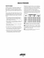
ENGINE OIL
ANTIFREEZE PROTECTION
Use a heavy duty engine oil with an API classification of CF
or CG4 or better, Change the engine oil after an initial 50
hours of break-in operation, and every 200 hours of operation
thereafter. For recommended oil viscosity, see the following
chart:
Operating Temperature
Oil Viscosity
Above 68"F (2D"C)
SAE 30 or 1OW-3D
41 "-68"F (5-2D"C)
SAE 20 or 1DW-3D
Below 41"F (5"C)
SAE 1DW-3D
Antifreeze concen1ration
23%
30%
35%
Freezing Temperature
WF
(-5"C)
8"F
(-13"C)
-4"F
(-20"C)
50%
-40"F
(-40"C)
COOLANT RECOVERY TANK
A coolant recovery tank kit is supplied with each
UNIVERSAL diesel engine. The purpose of this recovery
tank is to allow for engine coolant expansion and contraction
during engine operation, without the loss of coolant and
without introducing air into the cooling system. This kit is
provided and must be installed before running the engine.
A CAUTION: 00 not allow two or more brands of
engine oil to mix, Each brand contains its own additives;
additives of different brands could react in the mixture
to produce properties harmful to your engine.
COOLANT RECOVERY TANK
6
PREPARATIONS FOR INITIAL START-UP
o Check the DC electrical system. Inspect wire connections
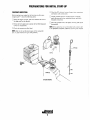
PRESTART INSPECTION
and battery cable connections.
Before starting your engine for the first time or after a prolonged layoff - check the following items.
o Visually examine the unit. Look for loose or missing
parts, disconnected wires, unattached hoses, and check
threaded connections.
o Check the engine oil1evel; add oil to maintain the level at
the high mark on the dipstick.
o Check the coolant level in the plastic recovery tank and at
o Check the fuel supply and examine the fuel filter/separator
the manifold.
bowls for contaminants.
NOTE: If the engine has not yet been filled with coolanT. refer
o Check the transmission fluid level.
to the ENGINE COOLING CIRCUIT section of this manual.
NOTE: Refer to the specifications pages in this manual for
fuel, oil, and transmission types and quantities.
_DIPSTICK
RECOVERY
TANK
MANIFOLD
(M-35B SHOWN)
7
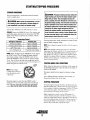
STARTING/STOPPING PROCEDURE
STARTING PROCEDURE
ACAUTloN: Prolonged cranking intervals without the
Place the transmission in neutral and advance the throttle
control to slightly open.
engine starting can result in the engine exhaust system
filling with raw water. This may happen because the
pump is pumping raw water through the raw water cool·
ing system during cranking. This raw water can enter the
engine's cylinders by way of the exhaust manifold once
the exhaust system fills. Prevent this from happening by
closing the raw water supply through-hull Shut-off,
draining the exhaust muffler, and correcting the cause
of the excessive engine cranking. Engine damage resulting from raw water entry is not a warrantable issue; the
owner/operator should keep this in mind.
A CAUTION: Make certain the transmission is in neutral. starting in gear could result in serious damage to
your transmission, your boat, and vessels nearby.
Turn the KEY SWlTCH to the ON position (2 o'clock)
PREHEAT: Depress the PREHEAT switch. The voltmeter and
panel lights, gauges and meters will be aClivated. The PREHEAT switch should be depressed in accordance with the
following chart:
TemperatureJPreheat
Abnospheric Temperalure
Once the engine starts, check instruments for proper oil pressure and battery charging voltage.
Preheating lime
+41°F(+5°C) or higher
Approx. 10 seconds
+4n(+5°C) to 2n (-5°C)
Approx. 15 seconds
+23°F(-5°C) or lower
Approx. 20 seconds
Limit of continuous use
30 seconds before cranking
NOTE: Never attempt to engage the starter while the engine is
running.
NOTE: Some unstable running may occur in a cold engine.
Depressing the Preheat switch/or /0-/5 second intervals 'will
help stabilize the engine RPM until the operating temperature reaches J70o-190°F (77°_88°C) and a propeller load is
applied to the engine. When the engine i~' running and the
preheat switch is depressed, a charging load on the DC alternator will be discernible.
START: While still depressing the PREHEAT switch, depress
the START switch. This will engage the starter solenoid.
Upon engine starting, release the START switch. Do not
release the PREHEAT switch until the oil pressure reaches
15 psi. Then as long as the high water temperature and low
oil pressure protective circuits do not activate, the engine will
remain energized and continue to run.
STARTING UNDER COLD CONDITIONS
VOLTAGE
DROP
Make certain the lubricating oil confonns with the ratings for
the prevailing temperature. Check the table on the engine oil
section of this manual.
NOTE: When starting:
A voltage drop will occur
when the preheat switch
is depressed.
The battery should be fully charged to minimize voltage
drop.
Use a sufficient amount of preheat to aid in starting, see
Temperature/Preheat chart On this page.
Should the engine not start when the START switch is
depressed for 10 to 20 secol!ds, release both switches and
wait 30 seconds; repeat the procedure above and preheat
longer. Never run the starter lor more than 30 seconds.
STOPPING PROCEDURE
To stop the engine, bring the throttle to an idle position and
place the transmission in neutral. Allow the engine to idle for
a few moments to stabilize temperatures. Pull the STOP lever
to shut down the engine. Then turn OFF the key 10 close
down the electric fuel pump and accessories.
Made certain the key switch is in the OFF position (12
o'clock). If the Key Switch is left ON. the battery will diScharge. An engine alarm buzzer is provided to warn the operator of this condition (Key Switch ON). The best method of
preventing the battery from discharge is to remove the key
from the Key Switch after stopping the engine.
8
BREAK-IN PROCEDURE
THE FIRST 50 HOURS
Breaking-in a new engine hasically involves seating the piston rings 10 the cylinder walls. This cannot be accomplished
hy long periods of running at iulc, nor hy early running at
full rpm. Idle running may glaze the eylinuer walls. resulting
in excessive oil consumption and smoky operation.
Excessive speed or heavy over-loading. especially with a
cold engine. may cause scoring of the cylinder walls. producing similar results. Operate the engine in moderation during
the 50-hour break-in period. (Don', baby the engine_ bu! do
not abuse it.)
Although your engine has experienced a minimum of one
hour of test operations to ensure accurate assemhly and
proper operation of all systems. hrcak~in lime is required.
The service life of your engine is dependent upon how the
engine is operated and serviced during its initial 50 hours of
usc.
Your new engine requires approximately 50 hours of initial
conditioning operation to hreak in cach moving part in order
to maximize the performance and service life of the engine.
Perform this conditioning carefully. keeping in mind the following:
1. Start the engine according to the Starting Procedure section in this manual; run the engine at fast idle while
checking that all systems (raw water pump, oil pressure,
battery charging) arc functioning.
2. Allow the engine to warm up (preferably by running at fast
idle) until the water temperature gauge moves into the
130 o -J40°F range.
NOTE: Allemptillg to reduce idle speed helow the minimum
3. While using the vessel, run the engine at varying engine
rpms for the first 25 hours.
shown may product' wisiahle ellgine operatioll and stalling.
NOTE: The propeller should he eithc!r 2 or 3 Node. It should
allow the enRine to rf!ach iiS maximum rated rpm at full open
throttle undenvay ill forward gear to ensure the ami/ahility
of rated horsepower whell Ilet'ded.
4. Avoid rapid acceleration, especially with a cold engine.
S. Usc caulion nol 10 overload the engine. The presence of a
gray or black exhaust, and the inahility of the engine 10
NOTE: See the TRANSMISSION section of this manual jor
hreak-ill illformation Oil your transmissio!l.
reach its full rated rpm, arc signs of an overload.
6. During the next 25 hours, the engine may be operated at
varying engine rpms, with short runs at full rated rpm.
Avoid prolonged idling during this break-in period.
9
THE DAILY ROUTINE
CHECK LIST
START YOUR ENGINE
Each day before starting your engine, take a few moments to
run this check list:
NOTE: See STARTING STOPPING PROCEDURE in Ihis
manual for more detailed instructions.
o Visually inspect the engine for fuel, oil, or water leaks.
o Check the oil level.
o Check the transmission fluid level.
I. Put transmission in neutral, throttle advanced.
2. Turn KEY to the ON position (2 o'clock)
3. Depress PREHEAT (IOta IS seconds).
o Check for loose wires at the alternator.
4. While pressing PREHEAT, push START.
When engine starts - release START.
o Check the starting batteries level (weekly)
D Check drive belts for wear and proper tension (weekly),
5. Hold PREHEAT until oil pressure reaches 15 psi andlor
alarm shuts Qff.
D Log your engine running time. These hours relate to
scheduled maintenance.
NOTE: Should engine fail to stan, wait 30 seconds, repeaT the
above procedure, and PREHEAT longer
o Check fuel supply; always keep fuel tank(s) as full as pos-
6. Allow a few minutes for the engine to warm at a comfortable rpm (approx. 1200 rpm), then reduce the rpm, shift
into gear, and get underway.
sible.
o Look for clean fuel in the fueVwater separator bowl.
o Check the coolant level in the plastic recovery tank.
A
CAUTION: When shifting the transmission, always
reduce the engine rpm to idle, then shift the transmission firmly from one direction to another_ A slight pause
in neutral will allow the propeller to slow. Shifting at
high rpm will damage the transmission/damper plate.
NOTE: Excessive loss of coolant indicates a cooling system
leak. Check the entire system. If necessary, use a cooling system pressure tester to pressurize the cooling system to locate
[he area of leakage. In cases of excessive coolant loss, refill
Ihe S1'Slem as oUllined ill Ihe ENGINE COOLING CIRCUIT
section ill this manuaL.
10
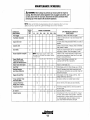
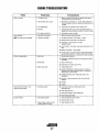
MAINTENANCE SCHEDULE
A
WARNING: Never attempt to perform any service while the engine is
running. Wear the proper safety eqUipment such as goggles and gloves, and
use the correct tools for each job. Disconnect the battery terminals when
servicing any of the engine's DC electrical equipment.
NOTE: Man)' a/the following maintenance jobs are simple but others are more
difficult and may require the expert knowledge of a service mechanic.
SCHEDULED
MAINTENANCE
CHECK
EACH
DAY
HOURS OF OPERATION
50
100
250
500
750 1000 1250
EXPLANATION OF SCHEDULED
MAINTENANCE
Diesel No.2 rating of 45 cetane or higher
Fuel/Waler Separator
0
0
Engine Oil Level
0
Oil level should indicate between MAX. and LOWon
dipstick.
CoolanlLevel
0
Check at recovery tank; if empty, check at manitold.
Add coolant if needed.
Drive Belts
0
Inspect for proper tension (3/8" to 1/2" depreSSion)
and adjust it needed. Check belt edges for wear
Visuallnspeclion ot Engine
0
Fuel Supply
NOTE:
Please keep engine suiface clean.
Dir! and oil will inhibillhe engine's ability
10 remain cool.
0
Engine Throttle and
Transmission Control
Cables and Shutoff Levers
Adjust Engine Idle Speed
Check for water and dirt in fuel (drain/replace filter
if necessary).
0
0
0
0
0
0
Starting Batteries
(and House Batteries)
0
Engine Oil and Filter
0
0
0
0
0
0
0
0
0
0
0
0
0
Initial engine oil & tilter change at 50 hrs .. then
change both every 100 hours.
At engine overhaul or cylinder head overhaul.
At first 100 hrs., then each year at wlntenzing.
0
Lubricate Panel Key
Switch with '"Lockeze"
0
Air Cleaner
Exhaust System
Initial change at 50 hrs, then change every 250 hrs.
Every 50 operating hours check electrolyte levels
and make sure connections are very tight Clean oft
excessive corrosion.
'Torque Cylinder Head
Hold Down Bolts
Transmission Fluid
Check tor loose tiltings, colter pins, etc.
Lubricate with WO-40 or equivalent
Adjust to (750-1200 rpm).
0
Fuel Filter
Check tor tuel, oil and water leaks. Inspect wiring
and electncal connections. Keep bolts & nuts tight
Check for loose belt tension.
0
0
0
0
0
0
0
0
11
0
0
Initial fluid change at 50 hrs, then every 250 hrs.
or once a year.
0
0
Clean the filter and element
Imtlal check at 50 hrs .. then every 500 hrs. Inspect
tor leaks. Check siphon break operation. Check the
exhaust elbow for carbon and/or corrosion buildup
on inside passages; clean and replace as necessary. Check that ali connections are tight
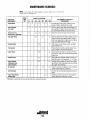
MAINTENANCE SCHEDULE
NOTE: Use the engine hour meter gauge to log your engine hours or record your
'
engine hours by running time.
SCHEDULED
MAINTENANCE
CHECK
EACH
DAY
HOURS OF OPERATION
750 1000 1250
EXPLANATION OF SCHEDULED
MAINTENANCE
50
100
250
500
Engine Hoses
0
0
0
0
0
0
0
Hose should be hard & tight. Replace if soft or
spongy. Check & tighten all hose clamps.
Heat Exchanger
Zinc Anode
0
0
0
0
0
0
0
Clean or replace anode. Open heat exchanger end
cap and clean out debris. Remove every 1000 hours
for professional cleaning and pressure testing.
Electric Fuel Lift
Pump Filter (if applicable)
0
0
0
0
0
0
Clean at 50 hours, then clean every 250 hours.
0
Remove pump cover and inspect impeller for wear;
replace if needed. Also replace gasket. Lubricate
both when reassembled. Inspect pump for internal
wear, cover plate wear and cam wear.
Raw Water Pump
0
0
Coolant System
0
0
Drain, flush, and refill cooling system With appro-
priate antiireeze mix.
Fuel Injectors
Check and adjust Injection opening pressure and
spray condition (see Engine Adjustments).
0
<Starter Motor
0
0
Check solenoid and motor for corrosion. Remove
and lubricate. Clean and lubricate the Starter motor
pinion drive.
<Preheat Circuit
0
0
Check operatIOn of preheat solenoid. Remove and
clean glow plugs; check resistance (1.1-1.2 ohms).
<Engine Cylinder
Compression and
Valve Clearance
0
0
Incorrect valve clearance will result in poor engine
pertormance; check compression pressure and timing,
and adjust valve clearances.
0
Check DC charge from a~ernator Check mounting
bracket; tighten electrical connections.
DC Alternator
0
0
Heat Exchanger
REngine Transmission
Damper Plate
0
Remove, have professionally cleaned and pressure
tested.
0
Chattering at idle and low rpms is an indication of
damper plate wear Remove and replace.
<UNIVERSAL recommends this service be pertormed by an authorized mechanic.
12
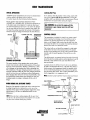
ENGINE COOLING CIRCUIT
DESCRIPTION
Drain the engine coolant by loosening the drain plug on the
engine block and opening the manifold pressure cap. Flush
the system with fresh water, then start the refill process. See
the Parts Identification photos in this manual for locations.
The engine is fresh water cooled (engine coolant) by an
engine-mounted heat exchanger. Raw water is pumped
through the heat exchanger by a gear-driven, positive displacement impeller pump. After the raw water cools the
engine coolant in the heat exchanger, it mixes with the
engine's exhaust gases, cools the exhaust gases, and discharges overboard.
NOTE: The petcack on the heat exchanger can also be used fo
help drain engine coolant.
AWARNING: Beware of the hot engine coolant. Wear
protective gloves.
The engine's coolant is circulated by a belt-driven centrifugal-type metal impeller pump mounted on the front of the
engine. The engine's coolant temperature is thermostatically
controlled.
To Refill With Coolant
With the engine running in idle, slowly pour clean premixed
coolant into the manifold.
The engine's coolant must be changed according to the maintenance schedule in this manuaL If the coolant is allowed to
become contaminated, it can lead to overheating problems.
NOTE: Open the petcacks on the thermostat housing and heat
exchanger to heip remove air from the system. When a steady
flow of coolant appears at the drain plug opening, close the
water drain plug and continue to fill the system until the
manifold remains full. Close the petcock on the heat
exchanger when antifreeze flows from it.
ACAUTIDN: Proper cooling system maintenance is
critical; a substantial number of engine failures can be
traced back to cooling system corrosion.
Monitor the coolant in the manifold and add as needed. Fill
the manifold to the filler neck and install the pressure
cap.The petcock on the thennostat should also be opened
when refilling to allow trapped air to escape.
COOLANT
ORAIN
Remove the cap on the coolanl recovery tank, fill with
coolant mix to halfway between LOW and MAX, and
replace the cap. Run the engine, close all petcocks and
observe the coolant expansion tlow into the recovery tank.
After checking for leaks. stop the engine and allow it to cool.
Coolant should draw back into the cooling system as the
engine cools down. Add coolant to the recovery tank if
needed. Clean up any spilled coolant.
M
~;AIEN:SISFOiiiliEO
f'
CAP
RECOVERY
TANK
NOTE: Periodically check the condition of the pressure cap.
Ensure that the upper and lower rubber seals are in good
condition and check that the vacuum valve opens and closes
tightly. Carry a spare cap.
MANIFOlO
A coolant recovery tank allows for engine coolant expansion
and contraction during engine operation, without any significant loss of coolant and without introducing air into the cooling system. This tank is best located at or above the engine
manifold level. and should be easily accessible.
13
ENGINE COOLING CIRCUIT
THERMOSTAT
RAW WATER COOLING CIRCUIT
A thermostat, located ncar the manifold at the front of the
engine, controls the coolant temperature as it continuously
flows through the closed cooling circuit. When the engine is
first started the closed thermostat prevents coolant from flowing (some coolant is by-passed through a hole in the thermostat to prevent the exhaust manifold from overheating). As
the engine warms up the thermostat gradually opens. The
thermostat is accessible and can be checked, cleaned, or
replaced easily. Carry a spare thermostat and gasket.
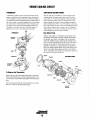
The raw water flow is created by a positive displacement
impeller pump. This pump draws water directly from the
ocean, lake, or river from a through-hull opening through a
hose to the water strainer. The raw water passes from the
strainer through the pump to a heat exchanger (through the
heat exchanger tubes) where it cools the engine's circulating
fresh water coolant. The raw water is then discharged into the
water injected exhaust elbow, mixing with, and cooling the
exhaust gasses. This mixture of exhaust gas and raw water is
driven through the stern tuhe and overboard.
Raw Water Pump
THERMOSTAT
TIle raw water pump is a self-priming, rotary pump with a
.
GASKET
non-ferrous housing and a neoprene impeller. The impeller
has flexible vanes which wipe against a curved cam plate
within the impeller housing, producing the pumping action.
On no account should this pump be run dry as water acts as a
lubricam for the impeller. There should always be a spare
impeller and impeller cover gasket aboard (an impeller kit).
Raw water pump impeller failures occur when lubricant (raw
water) is not present during engine operation. Such failures
are not warrantable, and operators are cautioned to make sure
raw water flow is present at start-up.
_
_._._._....
~I
THERMOSTAT~ i
RAW WATER PUMP
THERMOSTAT
HOUSING
SEAL
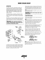
To Replace the Thermostat
WEAR PLATE
Remove the two cap .screws and disassemble as illustrated.
When assembling the new thermostat and gasket put a thin
coat of sealant on both sides of the gasket before pressing in
place.
Run the engine and check for normal temperatures and that
there are no leaks at the thermostat housing.
HOUSING
14
ENGINE COOLING CIRCUIT
Changing the Raw Water Impeller
12.
1. Close the raw water intake,
Mount the pump to the engine taking care thai the end
seal and gasket are in place. Do not tighten the pump
mounting screws, just finger tight.
2. Remove the inlet and outlet rx>rt hoses from the pump,
noting the port location and positioning.
13. Rca<;semhlc the hose connections and open the raw
water intake.
3. Remove the pump assembly and its gasket from the
engine.
14. Start the engine in idle, this will allow the pump to align
itself with its drive shaft.
4. Remove the three hex head screws that hold the housing
to the cover.
15. Stop the engine and tighten the pump assembly mounting screws.
5. Tap the housing/cover assembly on its side to loosen and
separate the cover from its housing.
16. Start and run the engine, check for leaks and check for a
norrnal operating temperature.
6. Remove the cover and its O-ring and remove the impeller
gasket and plate.
NOTE: Should a failure occur with the pumps internal parts
(seals and bearings) it may be more cost efficient to purchase
a new pump. The price of individual parts would almost
match the price of a new pump.
7. Remove the retaining ring (circ1ip) and pry out the
impeller. Take care not to lose the key off the shaft's keyway.
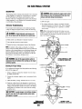
Heat Exchanger
ACAUTION: If any of the vanes have broken off the
The heat exchanger is a copper tUhe which encloses a number of small copper tubes. Raw water is pumped through the
small copper tubes and the freshwater coolant from the
engine is circulated around the copper tubes. The raw water
removes heat from the freshwater coolant. To keep the heat
exchanger operating efficiently, it should be removed from
the engine every 1000 hours to be thoroughly cleaned and
pressure tested.
impeller they must be found to prevent blockage in the
cooling circuit. They often can be found in the heat
exchanger.
8. Replace the gasket, impeller, and O-ring.
9. Apply a film of petroleum jelly or silicone to the inner
surface of the impeller housing.
HEAT EXCHANGER
NOTE: Just coat the surface, do not over apply.
10. Install the cover housing over impeller.
11. Install the three hex screws and tighten.
DRAIN
CLEAR OUT
DEBRIS
O-RING
POOR
ZINC ANODE
i
Zinc Anode
A zinc anode or pencil, is located in the raw water cooling circuit within the heat exchanger. The purpose of the zinc anode
is to sacrifice itself to electrolysis action taking place in the
raw water cooling circuit, therehy reducing the effects of electrolysis on other components of the system. The condition of
the zinc anode should be checked monthly and the anode
cleaned or replaced, a<; required. Spare anodes should he carried onboard. The area in the exchanger where the anode is
located should periodically he cleaned of anode dehris.
15
ENGINE OIL CHANGE
DRAIN THE SUMP
Replacing the Oil Filter
The engine oil should be warm. Remove the oil drain hose
from its attachment bracket and lower it into a container and
allow the oil to drain, or attach a pump to the end of the drain
hose and pump out the old oil. Make sure the oil drain hose
is capped and properly secured in its holder after all the old
oil has been drained.
When removing the used oil filter, you may find it helpful
and cleaner to punch a hole in the upper and lower portion of
the old filter to drain the oil from it into a container before
removing it. This helps to lessen spillage.
NOTE: Do not punch this hole without first loosening [he filter
to make certain it will come off!
NOTE: Thread size for the lube oil drain hose capped end is
An automotive filter wrench should be helpful in removing
the old oil filter. Place some paper towels and a plastic bag
around the filter when unscrewing it to catch any oil left in
the filter. Inspect the old oil tilter as it is removed to make
sure that the ruhber scaling gasket comes off with the old oil
filter. If this rubber sealing gasket remains sealed against the
engine block, gently remove it. When installing the new oil
filter element, wipe the filter gasket's sealing surface on the
engine block free of oil and apply a thin coat of clean engine
oil to the rubber gasket on the new oil filter. Screw the filter
onto the threaded oil filter stub, and tighten the filter firmly
by hand.
114 NPT
Always observe the old oil as it is removed. A yellow/gray
emulsion indicates the presence of water in the oil. Although
this condition is rare, it does require prompt attention to prevent serious damage. Call a competent mechanic if water is
present in the oiL Raw water present in the oil can be the
result of a fault in the exhaust system attached to the engine
and/or a siphoning of raw water through the raw water cooling circuit into the exhaust, filling the engine. This problem
is often caused by the poor location or the !ack of an antisiphon valve. See UNIVERSAL'S Installation Manual.
NOTE: Use genuine UNIVERSAL oil filters - generic filters
are nol recommended.
REFILL THE DlL SUMP
Add fresh oil through the filler cap. After refilling, run the
engine for a few moments while checking the engine's oil
pressure. Make sure there is no leakage around the new oil
filter or from the oil drain system, and then stop the engine.
Then check the quantity of oil with the lube oil dipstick. If
the engine requires additional oil, fill to, but not over, the
high mark on the dipstick.
OIL DRAIN HOSE
...r--,
OIL CONTAINER _ _
AWARNING: Used engine oil contains hannful contaminants. Avoid prolonged skin contact. Clean skin and
nails thoroughly using soap and water. l.aunder or discard clothing or rags containing used oil. Discard used
oil properly.
OIL FILTER
APPLY OIL TO GASKET - - - - WHEN ASSEMBLING
NEW FILTER.
/
SPIN·ON OIL FILTER
16
REMOTE OIL FILTER
INSTALLATION
Always install this kit with the oil filter facing down as illustrated.
This popular accessory is used to relocate the engine's oil filter from the engine to a more convenient location such as an
Contact your UNIVERSALIWESTERBEKE dealer for more
engine room bulkhead.
infonnation.
NOTE: Refer to the ENGINE OIL CHANGE page in this
manual/or instructions on removing the oil filter
NOTE: Westerbeke is not responsible for engine failure due to
incorrect installation a/the Remote Oil Filrer
To install, simply remove the engine oil filter and thread on
UNIVERSAL's remote oil filter kit as shown.
FASTEN SECURELY TO A BULKHEAO
(SCREWS ARE OWNER SUPPLIED)
APPLY A THIN COAT OF CLEAN OIL TO THE O-RING WHEN
INSTALLING THIS KIT. THREAD THE KIT ON, THEN TIGHTEN (BY
HAND) A 314 TURN AFTER THE O-RING CONTACTS THE BASE.
APPLY A THIN COAT OF CLEAN OIL TO THE FILTER GASKET
WHEN INSTALLING. ONCE THE FILTER CONTACTS THE BASE,
TIGHTEN IT A 314 TURN.
17
FUEL SYSTEM
FUEL WATER SEPARATOR
AWARNING: Shut off the fuel valve at the tank when
A primary fuel filter of the water separating type must be
installed between the fuel tank and the engine to remove
water and other contaminants from the fuel before they can
be carried to the fuel system on the engine.
servicing the fuel system. Take care in catching any fuel
that may spill. 00 NOT aI/ow any smoking, open flames
or other sources of fire near the fuel system when servicing. Ensure proper ventilation exists when servicing
the fuel system.
Most installers include a lype of filter/water separator with
the installation package as they are aware of the problems
that contaminants in the fuel can cause.
FUEL FILTERS
A typical fuel filter/water separator is illustrated in this diagram. This is the Rayeor Model 500 MA. Keep in mind that
if a water separator type filter is not installed between the
fuel supply tank and engine-mounted fuel system, any water
in the fuel will affect the fuel pump, engine filter, and injection equipment. The owner/operator is responsible for making
certain the fuel reaching the engine"s injection equipment is
free of impurities. This process is accomplished by installing
and maintaining a proper filtration/separation system.
The fuel injection pump and the fuel injectors are precisely
manufactured and they must receive clean diesel fuel, free
from water and dirt. To ensure this flow of clean fuel, the fuel
must pass through at least two fuel filters, a fueVwater separator and the engine'5 spin-on fuel filter. Visually inspect,
clean, and change these filters according to the maintenance
schedule in this manual.
I. Shut fuel supply off.
2. Loosen the fuel filter, turning counterclockwise with a filler wrench.
FROM
FUEL
3. Using a rag, wipe clean the sealing face on the housing
bracket so the new filter can be seated properly.
TANK
4. Lightly oil the sealing O-ring on the new filter. To re,install, turn the filter assembly clockwise carefully until the
O-ring contacts the sealing surface of the housing bracket.
Tum 2/3 further with the filter wrench.
TO ENGINE
5. Tum on the fuel and start the engine. The nonnal preheat
function should quickly prime the system and the engine
should start.
FUEL FILTER
WATERISEPARATOR
NOTE: The cartridge contains fuel. Take care not 10 spill it
during disassembl". Peiform the PRIMING TIlE FUEL
SYSTEM after replacing the spin-on Jilt"
DRAIN
FUEL FILTER
TO INJECTORS
SPIN-ON FUEL FILTER
18
FUEL SYSTEM
FUEL ADDITIVES
If it becomes necessary to bleed air from the system, use the
following procedure:
If fungus or bacteria is causing fuel problems, you should
have an authorized dealer correct these problems. Then use a
diesel fuel biocide to sterilize the fuel (follow the manufacturer's instructions).
Loosen all the high pressure injector lines (not injectors) and
crank the engine starter motor; as fue I spurts from between
the nut and the line, tighten the injector Jines in sequence and
then tighten the bleed screw.
SPARES
NOTE: Do not attempt this procedure on a hot engine.
A WARNING: Always wear protective clothing, safety
While the likelihood of having to service the fuel system at
sea is slim, the possibility does exist. Therefore, we recommend that banjo washers, injector seat washers, and a fuel filter be earned on board at all times. Purchase needed spares
from your local UNIVERSAL dealer or distributor. If a leak
should develop at a banjo washer that cannot be corrected by
a simple tightening of the fitting, replace the sealing washer.
glasses and gloves when bleeding high pressure injector
lines.
CANISTER
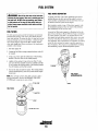
PRIMING (BLEEDING) THE FUEL SYSTEM
fiLTER ELEMENT
The on-engine fuel system is virtually self priming. Under
ordinary circumstances the engine's electric fuel lift pump,
which is energized by the key switch/preheat button, will
supply a continuous flow of fuel from the tank. This fuel is
drawn through the fuel/water separator to the engine lift
pump, the primary spin-on fuel filter, and the injection pump.
AIR CLEANERISILENCER
A WARNING: Do not allow smoking or open flames
(ENGINE M·3S8 SHOWN)
near the fuel system when servicing. Also provide proper
ventilation.
Air Cleaner/Silencer
Some UNIVERSAL engines use a replaceable air filter clement wrapped around a metal canister. This element can be
removed and brushed off or cleaned with an air hose. When
it become too contaminated it can be replaced. The canister
with its interior element should also be removed and cleaned
periodically. Simply wash the assembled unit in a non*flarn*
mabIe cleaning solvent. Use this same cleaning procedure for
other UNIVERSAL air cleaners that use a similar type canister.
TO FUEL FILTER
FROM FUEL TANK
NOTE: To operate efficiently a diesel engine must intake a
continuous volume of clear air. Hard starting, an erratic idle,
alld black exhaust smoke are all symptoms of a restricted air
intake.
1 L _ - - - CHECK AND CLEAN
filTER AT OIL CHANGE
TO FUEl FILTER
FUEL LIFT PUMPS
-
FROM FUEL TANK
19
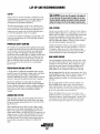
DC ELECTRICAL SYSTEM
DESCRIPTION
A
WARNING: Before starting the engine make certain
that everyone is clear Df mDving parts! Keep away frDm
sheaves and belts during test prDcedures.
The charging system consists of an alternator with a mounted
voltage regulator, an engine DC wiring harness, a mounted
DC circuil breaker, and a battery and connection wires.
Because of the use of integrated circuits (Ie's) the electronic
voltage regulator is very compact and is mounted internally
or on the back of the alternator.
.
5. Start the engine.
6. The voltage reading for a properly operating alternator
should be between 13.5 and 14.5 volts. If your alternator
is over- or undercharging, have it repaired at a reliable
service shop.
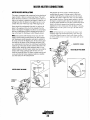
Alternator Troubleshooting
If you suspect that the alternator is not producing enough
voltage to charge the engine's battery, check the following:
NOTE: Before removing the alternator for repair, use your
voltmeter to ensure that 12 volts DC "excitation is preselll at
the R terminal if the previous lest showed ollly ballery voltage at the B output terminal.
A WARNING: A failed alternator can becDme very
hDt. Do nDt touch until the alternator has cODled dDwn.
o Make certain your alternator is securely mounted.
o Check the drive belts for proper tension.
o Inspect for loose or disconnected wires at the alternator.
NOTE: An isolator with a diode, a solenoid, or a battery
selector switch is usually mounted in the circuit to isolate the
balleries so the starting ballery is not discharged along with
the house batteries. If the isolator is charging the slarling
ballery but not the house ballery, the alternator is OK and
the problem is in the ballery charging circuit.
.14 PINK!1IlUE
A
WARNING: Shut Dff the engine battery switch Dr
discDnnect from the battery when wDrking Dn the engine
electrical system.
TYPICAL UNIVERSAL 51 AMP
ALTERNATOR CONNECTIONS
Checking for Proper Voltage
If you suspect the alternator has failed perform the following
tests with the engine off:
1. Using a voltmeter, connect the voltmeter red wire clip to
the output terminal B+.
2. Connect the voltmeter negative wire to any ground on the
engine.
3. Check the battery voltage. It should read 12 to 12 volts.
'14 PINK/8LUE
4. Check the voltage between the alternator (+) positive ter~
minai B and any engine ground. If the circuit is good, the
voltage at the alternator should be the same as the battery
(unless there's an isolator in the circuit, then the reading
would be zero).
='1iiif<:=;cz::n;E§ '14 PINKIBLUE
L __JOI~~~==- 814 BROWN
A CAUTION: TD aVDid damage tD the battery charging
circuit, never shut Dff the engine battery SWitch when
the engine is running!
.1U RED
==!t:::<l(5l:'5,
OPTIONAL 72 AMP
ALTERNATOR CONNECTIONS
20
DC ELECTRICAL SYSTEM
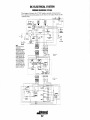
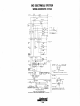
ENGINE 12 VOLT DC CONTROL CIRCUIT
A WARNING: Sulfuric acid in lead batteries can
The engine has a 12 volt DC electrical control circuit that is
shown on the wiring diagrams that follow. Refer to these diagrams when troubleshooting or when servicing the DC electrical system on the engine.
cause severe burns on skin and damage clothing. Wear
protective gear.
A CAUTION: When quick charging the battery with an
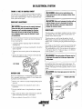
DRIVE BELT ADJUSTMENT
external charger, be sure to disconnect the battery
cables from the battery so the quick charge doesn't
damage the alternator diodes.
A
CAUTION: Drive belts must be properly tensioned.
Loose drive belts will not provide proper alternator
charging and will eventually damage the alternator.
Drive belts that are too tight will pull the alternator
out of alignment and/or cause the alternator to wear
out prematurely.
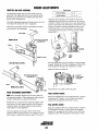
GLOW PLUGS
The glow plug is a small heater installed in each pre-combustion chamber. They run off the engine starting bauery and
become red hot when activated.
The glow plugs are wired through the preheat solenoid.
When preheat is pressed at the control panel this solenoid
should "click" on and the glow plug terminal should begin to
get hal.
Belt tension adjustment is made by pivoting the alternator on
its base mounting bolt.
1. Loosen the alternator adjusting strap bolt and the base
mounting bolt
Glow plugs can be checked by unscrewing and holding them
against a good ground (engine block) and turning them on.
The tip should glow red hot. You can also usc an ammeter to
test the power drain (8 to 9 amps per plug), or an ohmmeter
to test resistance (I.! to 1.2 ohms).
2. Pivot the alternator on the base mounting bolt to the left or
right as required.
3. Tighten the base mounting bolt and the adjusting strap
bolL
A WARNING: These glow plugs will become very hot
4. Operate the engine for about 5 minutes at idle, then shut
down and recheck belt tension.
to the touch. Be careful not to burn your fingers when
testing plugs.
BElT TENSION
Re-install the plugs in the engine and test them again. The
plugs should get very hot (at the terminal end) with 20 to 25
seconds. If the plugs don't heat up quickly, check for a short
circuit.
A CAUTION: Do not keep glow plug on for more than
BATTERY CARE
30 seconds.
Review the manufacturer's recommendations and then establish a systematic maintenance schedule for your engine starting batteries and house batteries.
_GLOW PLUG
PREHEAT GLOW PLUGS
TERMINAL
o Monitor your voltmeter for proper charging during engine
~~.
operation.
o Check the electrolyte level and specific gravity with a
CENTRE SHAFT
hydrometer.
~
;;;:;' ""'
o Use only distilled water to bring electrolytes to a proper
SILICON CAP y/""
lcvel.
o Make certain that battery cable connections are clean and
tight to the battery posts (and to your engine).
o Keep your batteries clean and free of corrosion
FROM PREHEAT
SOLENOID
TUBE
21
J
- ' " ' ---
DC ELECTRICAL SYSTEM
WIRING DIAGRAM #31944
This diagram illustrates the 12 VDC negative ground electrical circuit.
Two optional instrument panels are also shown: the Captain Panel and the
Admiral Panel.
9'! rlHi:iIlH
NOTE;
AN ON-OFF SWITCH
SHOULD BE
INSTALLED BE1WEEN
THE BATIERY AND
STARTER TO DISCON-
NECT THE BATIERY IN
ADMIRAL
AN EMERGENCY AND
PANEL
WHEN LEAVING THE
BOAT A SWITCH WITH
A CONTINUOUS RATING OF 175 AMPS AT
12 vae WILL SERVE
THIS FUNCTION. THIS
SWITCH SHOULD NOT
BE USED TO MAKE OR
BREAK THE CIRCUIT.
-----------------------------"
~ 11
CAPTAIN
PANEL
~~
------:
I
.1
I~
1~
____ ~====1"~g~~ll
___
22
DC ELECTRICAL SYSTEM
WIRING SCHEMATIC #31944
...
"yo<
. ."---""'@
,0,
t------:~:..~-;'~,
"
i
" ..n.
-
,------------ ------,
"' ,' ,'
,:::,~
1
,~'''T''''
CAPTAIN
PANEL
~
~ .~Qf~--~--~~~
"till "".,
.'.
51
Rw
o
AMP
AI JEBNATOR
PRESTO! ITF ]? Af'.'P
AI T
'3C 0:. liB l:l!:_ 315 Ii. , _ _ _ _ _ _ _ _ _ _ _ _ _ _ _ __
SHWPARD ALTERNA10~ ON TN£
'3~
a:
loeB i::_
t
'He n
r
M"'-""T;;-
~
,0<0"."
OPT I aNAl
AI HENAIORS ®
,.,. "'A to •• '''''A ,<,,, .. Too,
... · ... ,""r.'v"!J 'xu '''g ,,"n ,,,.u !,,,rIARo"
23
o 'IN I VERSAI
PRESTO! I TF
ON
o i
AMP
AI
ENGINE ADJUSTMENTS
THROTTLE AND STOP ASSEMBLY
Firing Orders
The throttle and engine stop levers arc located on the outboard side of the engine just below the fuel injection pump.
Brackets are provided for owner-installed push-pull cables
that run to the steering station.
3 Cylinder Models
1- 3- 2
4 Cylinder Models
1-3-4-2
Adjust the valves beginning with Cylinder #1. Rotate the
crankshaft slowly and observe the operation of the valves for
Cylinder #1. Watch for the intake valve to open indicating the
piston is on its intake stroke (the piston is moving down in the
cylinder). Continue to rotate the crankshaft slowly and look
for the intake valve to close. The piston is now starting its
compression stroke (the piston is moving up in the cylinder
lowards IDC).
The throttle high speed adjustment has been factory set and is
wire locked. The throttle idle screw is adjustable.
These levers and brackets should be periodically lubricated
and checked for loose fastenings.
STOP Lt"tH·--..
MODELS M3-20
SPEED ADJUSTMENT
SET)
TIMING
MARK
LEVER
Watch the timing hole in the bell housing for timing numbers
to appear. Position the ITC Mark in alignment with the notch
in the timing hole. The piston in Cylinder #] is at TDe.
STOP AND THROmE LEVERS
Adjust the valves in Cylinder #1.
HIGH SPEED ADJUSTMENT
(FACTORY SET)
MODELS M-25 & M-35
Proceed to the nexl cylinder in the firing order.
VALVE CLEARANCE ADJUSTMENT
Three cylinder models
NOTE: Valve adjustment should nOl be necessary under norma/ operating conditions. These adjustments, when required,
should be performed by an authorized mechanic
Rotate the crankshaft 240 0 in the normal direction of rotation
and adjust the #3 Cylinder's valves. Rotate the crankshaft
another 2400 and adjust the #2 Cylinder's valves.
Remove the valve rocker cover to expose the engine's valve
train. Remove the glow plugs from each of the cylinders to
enable the engine to be easily rotated by hand to position
each cylinder for valve adjustment.
Four cylinder models
Rotate the crankshaft] 80 0 in the normal direction of rotation
and adjust the #3 Cylinder's valves. Rotate the crankshaft
another ]800 and adjust the #4 Cylinder's valves. Rotate the
crankshaft another 180 0 and adjust the #2 Cylinder's valves.
Valves are adjusted with the piston in the cylinder being
adjusted at TOC (Top Dead Center) of its compression stroke.
Each cylinder is adjusted following the engine's firing order.
24
WATER HEATER CONNECTIONS
WATER HEATER INSTALLATIONS
The pressure cap on the engine's manifold should be
installed after the engine's cooling system is filled with
coolant. Finish filling the cooling system from the remote
tank after the system is filled and is free of air and exhibits
good coolant circulation. During engine operation, checking
the engine's coolant should be done at the remote tank and
not at the engine manifold cap. The hose connection from the
heater to the remote expansion tank should be routed and
supported so it rises continuously from the heater to the tank,
enabling any air in the system to rise up to the tank and out
of the system.
This engine is equipped with connections for the plumbing of
engine coolant to heat an on-board water heater. The water
heater should be mounted in a convenient location either in a
high or low position in relation to the engine, so that the connecting hoses from the heater to the engine can run in a reasonably direct line without any loops which might trap air.
Hoses should rise continuously from their low point at the
heater to the engine so that air will rise naturally from the
heater to the engine. If trapped air is able to rise to the heater,
then an air bleed petcock must be installed at the higher fitting on the heater for bleeding air while filling the system.
NOTE: Air bleed petcocks are located on the engine's heat
exchanger and on the thermostat housing. Open these petcocks when filling the engine'sJresh water S}'Slel7l to allmA'
air in the coolant circuil !O escape. Close lighl(V after al! the
air is removed.
NOTE: If any portion of the heating circuit rises above the
engines closed cooling system pressure cap, then a pressurized (aluminum) remote expansion lank must be installed in
the circuit to become the "highest point. Tee the remote expansion tank into the heater circuit, choosing the higher of the
Mo connections for the return. Tee at the heater, and plumb a
single line up to the tanks location and the other back to the
engine's return. Instal/the remote expansion lank in a convenient location so the fresh water coolant level can easily be
checked. The remote expansion lank will now serve as a
check and system fill point. The plastic coolant recovery lank
is not used when the remote expansion lank kit is installed,
since this tank serves the same function.
->::,....
~
HEATER BELOW THE ENGINE
WATER
HEATER
/.,
---y~
HEATER ABOVE THE ENGINE
REMOTE EXPANSION
TANK
j\
.
'l:
1°
I
t ~,
THERMOSTAT HOUSING
WATER
HEATER
THERMOSTAT
HOUSING
25
ENGINE TROUBLESHOOTING
The following trouble shooting chart describes certain problems, the probable causes of the problems, and the recommendations to overcome the problems.
Problem
Key switch on, PREHEAT switch
depressed: no panel indications:
fuel solenoid or electrical fuel pump
NOTE: The engine s electrical system is protected by a 20Ampere manual reset circuit breaker located on the bracket
on [he left side of [he engine. The preheat solenoid is
moullled on lhe same bracket.
VerificationJRemedy
Probable Cause
1. Battery Switch not on.
1. Check switch and/or battery connections.
2. 20-Amp circuit breaker tripped.
2. Reset breaker; if breaker trips again. check preheat solenoid
J. 10-Amp breaker tripped.
J. Check voltage at and after breaker.
4. Loose battery connections.
4. Check (+) connection to starier solenoid and (-) connection to
engine ground stud. Check battery cable connections.
5. Preheat solenoid not operating.
5. Check solenoid.
1. Connection to solenoid faulty.
1. Check connection at solenoid.
2. Faulty START switch.
2. Check switch with ohmmeter.
J. Faulty solenoid.
J. Check that 12 volts are present at starter solenoid activation
4. loose battery connections.
4. Check (+) connection to starter solenoid and (-) connectIOn to
engine ground stud. Check battery cable connections.
circuit and check Circuit for shorts to ground.
Key switch on, PREHEAT switch
depressed: START switch depressed;
no starter engagement.
connection.
Engine cranks, but does not
start.
Engine can't be stopped.
5. Low batteries.
5. Check battery charge state.
1. Faulty fueling system.
1. Check that fuel valves are open.
2. Preheat solenoid faulty.
2. Check solenoid.
J. low compression.
J. Compression test the engine.
1. Faulty shut-off lever at engine.
1. Reconnect shut off lever
2. Push-pull shut off cable from steering
2. Reconnect push-pull cable.
station to engine disconnected.
Engine stops.
1. Fuelhft pump failure.
1. Fuel lift pump should make a distinct ticking sound. Replace
pump with spare.
2. Switches and/or wiring loose
2. Inspect wiring for short circuits and loose connections.
Inspect switches for proper operation.
or disconnected.
Battery not charging
J. Fuel starvation.
J. Check fuel supply, fuel valves, fuel lift pump.
4. 20 Amp circuit breaker tripping.
4. Check for high DC amperage draw during operation
Ensure breaker is not overly sensitive to heat which would
cause tripping.
5. Exhaust system is restricted.
5. Check for blockage. collapsed hose, carbon buildup at
exhaust elbow.
6. Water in fuel.
6. Pump water from fuel tank{s); change filters and
bleed fuel system.
1. Alternator drive.
1. Check drive belt tension. Aternator should turn freely. Check
for loose connections. Check output with voltmeter. Ensure 12
volts are present at the Exc terminal
26
ENGINE TROUBLESHOOTING
Problem
Battery runs down.
Probable Cause
VerificalionJRemedy
1. Oil Pressure switch.
1. Observe if gauges and panel lights are activated when engine is
not running. Test the oil pressure switch.
2. High resistance leak to ground.
2. Check wiring. Insert sensitive (0 •. 25 amp) mete in battery lines.
(Do not start engine.) Remove connections and replace after short
is located.
3. Low resistance leak.
3. Check all wires for temperature fise to locate the fault.
4. Alternator.
4. Disconnect alternator at output. after a good battery charging. If
leakage stops, remove alternator and bench test. Repair or replace.
5. Poor battery connections.
5. Check cable connections at battery.
Engine overheats.
1. Raw water not circulating.
1. Broken or loose belt at raw water pump
NOTE: Shut engine down immediately.
2. Coolant not circulating.
2. Raw water pump failure. Check impeller - replace.
2a. Obstruction at raw water intake or raw water filter.
2b. Thermostat - remove and test in hot water.
Replace thermostat.
2c. Loss of coolant - check hoses. hose clamps. drain plug, etc. for
leaks.
2d. Broken or loose belts - tighten/replace.
2e. Air leak in system; run engine and open cooling system petcocks,
heat exchanger, manifold. etc. to bleed air. Add coolant as needed.
Exhaust smoking problems
1. Blue smoke.
1. Incorrect grade of engine oiL
la. Crankcase is overfilled with engine oil (oil is blowmg out through
the exhaust).
2. Engine is running cold.
2. White smoke.
2a. Faulty injector or incorrect injector timing.
3. Black or gray smoke.
3. Improper grade of fuel.
3a. Fuel bum incomplete due to high back pressure :n exhaust or
insufficient air for proper combustion (Check for restrictions in
exhaust system; check air intake).
3b. Improperly timed fuel system, misadjusted valves or poor
compression.
3e. Lack of air - check air intake and air filter. Check for proper
ventilation.
3d. Overload.
3e. Propeller.
Transmission will not shift in or out
of gear, or drive the vessel.
1. Transmission faHure.
la. Check cable connections at steering station and at
transmission lever.
lb. Check transmission fluid.
1&. Check shaft couplings or engine damper plate.
ld. Check engine's damper plate.
Excessive vibration
1. Faulty engine alignment
1. Check the shaftJtransmlssion coupling.
2. Cutless bearings. support strut and
2. Inspect propeller and shaft.
la.lnspect all engine mounts,
propeller could all be suspect.
.~
MARINE POWER
27
CONTROL PANEL TROUBLESHOOTING
MANUAL STARTER DISCONNECT (TOGGLE SWITCHES)
NOTE: The engine control system is protected by a 20 amop manual resel circuil breaker
located on the engine as close as possible to the power source.
Problem
Probable Cause
VerilicalionJRemedy
PREHEAT depressed, no panel indications
fuel solenoid, electric fuel pump and
preheat solenoid not energized.
1. Oil Pressure switch,
1. Check switches and/or battery connections.
2. 20 amp circuit breaker tripped.
2. Reset breaker. If opens again, check preheat solenoid circuit
and run circuit for shorts 10 ground.
START SWITCH DEPRESSED, no starter
engagement.
1, Connection to solenoid faulty.
1. Check connection.
NO IGNITION, cranks, does nol start.
2. Faulty switch
2. Check switch with ohmmeter.
3. Faulty solenoid.
3. Check that 12 vol:ts are present at the solenoid connection.
4. loose battery connections.
4. Check battery connections.
S. Low battery.
S. Check battery charge state.
1. Faulty fueling system.
1. Check for fuel.
2. Check for air in the fuel system.
2. Allow system to bleed.
3, Faulty fuel lift pump.
3. Replace fuel lift pump.
NDT CHARGING BATIERY
1. Faulty alternator drive.
1. Clleck tile drive belt and its tension. Be sure the alternator
turns freely. Check for loose connections. Check the
output with a voltmeter. Ensure 12V are present at tile
regulator terminal.
BATIERY RUNS DOWN
1. Oil pressure SWltcll.
1. Observe if the guages and panel lights are activated when the
2. High resistance leak to ground.
2. Check the wiring. Insert sensitive (0-.25 amp) meter in battery
lines (Do NOT start engine). Remove connections and replace
after short is located.
3. low resistance leak to ground.
3. Check all wires for temperature riuse to locate the fault.
4. Faulty alternator.
4. After a good battery charging, disconnect alternator at output
If leakage stops. Remove alternator and benck test. Repair or
replace.
engine is not runnmg. Test tile oil pressure switch.
TROUBLESHOOTING WATER TEMPERATURE AND OIL PRESSURE GAUGES
If the gauge reading is other than what is normally indicated
by the gauge when the instrument panel is energized, the first
step is to check for 12 volts DC between the ignition (B+)
and the Negative (B-) terminals of the gauge.
If both of the above gauge tests are positive, the gauge is
undoubtedly OK and the problem lies either with the conductor from the sender to the gauge or with the sender.
If either of the above gauge tests are negative, the gauge is
probably defective and should be replaced.
Assuming that there is 12 volts as required, leave the instrument panel energized (key switch on) and perform the
following steps:
Assuming the gauge is OK, check the conductor from the
sender to the sender terminal at the gauge for continuity.
1. Disconnect the sender wire at the gauge and see if the
gauge reads zero, which is the normal reading for this situation.
Check that the engine block is connected to the ground.
Some starters have isolated ground terminals and if the battery is connected to the starter (both plus and minus terminals), the ground side will not necessarily he connected to the
block.
2. Connect the sender terminal at the gauge to ground and
see if the gauge reads full scale, which is the normal reading
for this situation.
28
TACHOMETER TROUBLESHOOTING
TACHOMETER/HOURMETER
Calibration
The tachometerlhounneter used in propulsion engine instru~
ment panels contains two separate electrical circuits with a
common ground. One circuit operates the hounneter and the
other the tachometer. The hounneter circuit operates on 12
volts alternator charging voltage supplied to the (+) terminal
on the back of the instrument.
a. With a hand-held tach on the front of the crankshaft pulley retaining nut or using a strohe type lach, read the front
crankshaft pulley rpm.
b. Adjust the tachometer with a sma\! Phillips type screwdriver through the calibration access hole in the rear of the
tachometer. Zero the tach and bring it to rpm scI by using
a strobe or hand tach (verify rpm at idle and at high speed
1500 - 2500 - 3000 rpm). Adjust the tach as needed.
The tachometer circuit operates on AC voltage 6 - 8 Yolts, fed
from one of the diodes in the alternator and supplied to the
"tach iop." terminal while the engine is running, and the
alternator producing battery charging voltage 13.0 - 14.8
volt, DC.
NOTE: Current modellachometers use a coarse adjustment
dial to set the tachometer [0 the crankshaft pulley rpms_ The
calibrating screw is [hen used for fine luning.
The following are procedures to follow when troubleshooting
a fault in either of the two circuits in a tachometerlhounneter.
LIGHT
Hourmeter Inoperative
TACH INP
Check for the proper DC voltage between (+) and (-) terminals.
a. Voltage present -
meter is defective -
repair or replace.
b. Voltage not present - trace (+) and (-) electrical connections for fault. (Jump 12 volts DC to meter (+) terminal to
verify the operation.)
CALIBRATE
Tachometer Inoperative
a. Voltage present - attempt adjusting meter through calibration access hole. No results, repair or replace meter.
h. AC voltage not present output voltage.
EARLY MODEL TACHOMETERS
(-) TERMINAL
check for proper alternator DC
c. Check for AC voltage at tach terminal on alternator to
ground.
d. Check electrical connections from "tach inp." terminal to
alternator connection.
1-) TERMINAL
~~
Tachometer Sticking
a. Check for proper AC voltage between "tach inp." tenninal
and (-) terminal.
h. Check for good ground connection between meter (-) terminal and alternator.
C.
Check that alternator is well grounded to engine block at
alternator pivot bolt.
COARSE AOJIJST"ENT--f:jj~
1-) TERMINAL
CURRENT TACHOMETER
~"ZlIt----I+)
FINE CAI.lBR'ATING.-~~~:"~
29
TERMINAL
INP
HBW TRANSMISSION
INITIAL OPERATION
Locking the Prop
All HBW marine transmissions are test-run on dynamometer
with the engine at the factory prior to delivery.
For safety reasons the fluid is drained before shipment.
If you prefer to lock the propeller when sailing. simply shift
into reverse. Do not shift into forward gear. (Locking the
propeller shaft by an additional hrakc is unnecessary). Return
the shift lever to neutral before starting the engine.
Fill the gearbox with Automatic Transmission Fluid
(DEXRON II or DEXRON III). The fluid level should be up
to the index mark on the dipstick. To check the fluid level,
just insert the dipstick, do not screw it in. Screw the dipstick
A. WARNING: 00 not start the engine with the
transmission in gear. Always return the shift lever
tooneutral!
into the case after the fluid level is checked, and tighten. Do
not forget the sealing ring under the hex head of the dipstick.
Check for leaks and change the fluid after the first 50 hours.
CONTROL CABLES
TO CHECK FLUID LEVEL
The transmission is suitable for single lever remote control.
Upon loosening the retaining screw, the shift lever can be
moved to any position required for the control elements
(cable or rod linkage). Make certain that the shift lever docs
not contact the shift lever cover plate: the minimum distance
between lever and cover should be O.5mm.
The control cable or rod should be arranged at a right angle
to the shift lever when in the neutral position. The neutral
position of the operating lever on the control console should
coincide with the neutral position of the shift lever on the
gear box.
FLUID LEVEL
The shifting travel, a<; measured at the pivot point of the shift
lever, between the neutral position and end positions A and B
should be at least 35mm for the outer and 30mm for the
inner pivot point.
DIPSTICK FLUID LEVEL
GEARBOX OPERATION
The neutral position of the operating lever on the control
console must coincide with the neutral position of the actuating lever on the transmission. Shifting is initiated by a cable
or rod linkage via the actuating lever and an actuating cam.
The completion of the gear changing operation is servo-automatically controlled within the gear. Gear changing should be
smooth, not too slow, and continuous (without interruption).
Direct changes from forward to reverse are permissible, since
the multiple-disc clutch permits gear changing at high rpm,
including sudden reversing at top speeds in the event of
danger.
A greater amount of shift lever travel is in no way detrimental, and is recommended. However, if the shift lever travel is
shorter, proper dutch engagement might be impeded which,
in tum, would mean premature wear. excessive heat generation and clutch plate failure. This would be indicated by slow
clutch engagement or no engagement at all.
NOTE: Check jor proper shift lever travel at least each season.
CABLEBR~
WHEN UNDER SAIL OR BEING TOWED
FORWARD
A
0)
NEUTRAL
0
\
.. -_ .. - ~ :,\\1;"'\-\;;;:.: .'
® I CONTROL SHIFTING
Rotation of the propeller without load such as when the boat
is sailing, being towed, or anchored in a river, as well as
CABLE~
operalion of the engine with the propeller stopped (for charg-
ing the battery), will have no detrimental effects on the
tranmission
COUNTER CLOCKWISE
TRANSMISSION COVER PLATE
NOTE: When the boat is sailing (engine ofJ), the gear lever
can be set in the neutral pOSition, the propeller (flOW at idle)
can free wheel without causing any problem.
Q.,
00 NOT LOOSEN
THESE FOUR BOLTS
SHIFTING LEVER HUB-----..
30
CLOCKWISE
0.5 mm CLEARANCE
SHIFTING
LEVER
HBW TRANSMISSION
Checking the Bowden Cable or Rod Linkage
A
WARNING: The position of the cover plate underneath the actuating lever is factory-adjusted to ensure
equal shift lever travel from neutral position to A and B.
If this side shift cover is removed or in any way tampered with, the transmission warranty will be void.
Authorized Hurth personnel only may adjust or remove
this cover.
The Bowden cable or rod linkage should be checked at regular intervals. Check the neutral position of the operating lever
(on the control console) and the actuating lever (on the gearbox). The minimum lever travel from the neutral position to
the operating positions (0 - A = 0 - B) should be 35mm for
the outer and 30mm for the inner pivot point. Make certain
that these minimum values arc safely reached. Check the
cable or rod linkage for easy movahility and proper attachment.
NOTE: When installing the gearbox, make cenain that shifting
Propeller Shaft Alignment
is not impeded by restricted movability of the Bowden cable
or rod linkage, by unsuirabl:..,-' positioned guide sheaves, too
small a bending radius, etc. A shift cable attachment is provided with each transmission
The engine's transmission must be exactly aligned with the
propeller shaft. Misalignment will create excessive shaft and
bearing wear and can cause the transmission'5 rear seal to
leak fluid.
MAINTENANCE
Transmission Fluid
The shaft/transmission coupling alignment should be checked
periodically and always when the boat is being recommissioned after winter storage.
To ensure trouble-free operation of the gearbox, only use
Automatic Transmission Fluid (ATF). (Dexron II or III).
Lay-up/Winterize
Capacity
If the transmission is not used for periods of more than one
year, it should he completely filled with transmission fluid to
prevent corrosion. Protect the input shaft and the output
flange by means of an anticorrosive coating, as required.
Add the fluid quantity for the proper model transmission to
the gearbox. After filling, check the fluid level with the dipstick. Adjust level as needed. Install the dipstick with the
sealing washer. operate unit, check fluid, check for leaks.
Transmission Fluid
HBW TRANSMISSION
Quantity
HBW50
0.29 Quarts (0.. 30 Liters)
HBW 100
0.33 Quarts (0.35 Liters)
HBW 150
0.59 Quarts (0.56 Liters)
HBW 150V
1.10 Quarts (1.05 Liters)
HBW 250
1.84 Quarts (1.75 Liters)
SHAFT
Fluid Change
Change the fluid for the first time after about 50 hours of
operation, then every 250 operating hours or at least once a
year or when you change engine oiL When changing the
fluid, also check the gearbox cooling device and clean or
replace it as necessary.
NOTE: When changing the fluid. take care flot to lose the
drain plug sealing H'Qsher. The drain plug will leak without
rhis sealing washel:
COUPLING
31
LAY-UP AND RECOMMISSIONING
LAY-UP
A.. CAUTION: 00 not leave the engine's old engine oil
Many owners rely on their boatyards to prepare their craft,
including engines and generators, for lay-up during the offseason or for long periods of inactivity. Others prefer to
accomplish lay-up preparation themselves.
in the sump over the lay-up period. Engine oil and combustion deposits combine to produce hannful chemicals
which can reduce the life of the engine's internal parts.
The following procedures will allow you to perform your
own lay-up and recommissioning, or you may use them as a
check list for others. These procedures should afford your
engine protection during a lay-up and also help familiarize
you with the maintenance needs of your engine.
FUEL SYSTEM
Top off your fuel tanks with No.2 diesel fueL Fuel additives
should be added at this time to control algae, and a fuel conditioner such as STABIL. Care should be taken that the additives used are compatible with the primary filter/water
separator used in the system. Change the element in your primary fuel filter/water separator, if the fuel system contains
one, and clean the separator sediment bowl.
If you have any questions regarding lay-up procedures, call
your local servicing dealer; he will be more than willing to
provide assistance.
PROPELLER SHAFT COUPLING
Change the fuel filter elements on the engine and bleed the
system as needed. Start the engine and allow it to run for 510 minutes to make sure no air is left in the fuel system.
Check for any leaks that may have been created in the fuel
system during this servicing. correcting them as needed.
The transmission and propeller half couplings should always
be opened up and the bolts removed when the boat is hauled
out of the water or moved from land to water, and during
storage in a cradle. The flexibility of the boat often puts a
severe strain on the propeller shaft Or coupling, or both, while
the boat is taken out or put in the water. In some cases, the
shaft has actually been bent by these strains. This does not
apply to small boats that are hauled out of the water when
not in use, unless they have been dry for a considerable
period of time.
RAW WATER CIRCUIT
Close the through-hull fitting: Remove the raw water intake
hose from the fitting. Place the end of this hose into fl 5-galIon bucket of clean fresh water. Before starting the engine,
check the zinc anode found in the heat exchanger on the
engine and clean or replace it as required. Clean the raw
water strainer, if one is installed in the inside of the hull.
FRESH WATER CODLING SYSTEM
A 50-50 solution of antifreeze and distilled water is recommended for use in the freshwater coaling system at all times.
This solution may require a higher concentration of
antifreeze, depending on the area's winter climate. Check the
solution to make sure the antifreeze protection is adequate.
Start the engine and allow the raw water pump to draw fresh
water through the system. When the bucket is empty, stop the
engine and refill the bucket with an antifreeze solution
slightly stronger then needed for winter freeze protection in
your area.
Should more antifreeze be needed, drain an appropriate
amount from the engine block and add a more concentrated
mixture. Operate the engine to ensure a complete circulation
and mixture of the antifreeze concentration throughout the
cooling system. Now recheck the antifreeze solution's
strength.
Start the engine again and allow all of this mixture to be
drawn through the raw water system. Once the bucket is
empty, stop the engine. This antifreeze mixture should protect the raw water circuit from freezing during the winter layup, as well as providing corroSIOn protection.
Remove the impeller from your raw water pump (:-;ome
antifreeze mixture will accompany it, so catch it in a bucket).
Examine the impeller. Acquire replacement. if needed, and a
cover gasket. Do not replace the impeller (into the pump)
until recommissioning, but replace the COver and gasket.
LUBRICATION SYSTEM
With the engine warm, drain all the engine oil from the oil
sump. Remove and replace the oil filter. (Place some paper
towels and a plastic bag around the filter to catch the oil during its removal.)
When installing the new oil filter, be sure to apply a small
amount of oil on the rubber sealing gasket at the base of the
filter. Fill the sump with the correct amount of oil for your
engine model. (Refer to the SPECIFICATIONS section of this
manual.) Usc an oil with an API specification of CF or CG4
or better. Run the engine and check for proper oil pressure
and make sure there are not leaks. Stop the engine, check oil
level and add oil as needed to bring level to dipstick full
mark.
32
LAY-UP AND RECOMMISSIONING
STARTER MOTOR
RECOMMISSIONING
Lubrication and cleaning of the starter drive pinion is advisable, if access to the starter permits its removal. Make slIre
the battery connections arc shut off before attempting to
remove the starter. Take care in properly replacing any electrical connections removed from the starter.
The recommissioning of your UNIVERSAL engine after a
seasonal lay-up generally foHows the same procedures as
those presented in the PREPARATIONS FOR STARTING
section regarding preparation for starting and normal starts.
However, some of the lay-up procedures will need to be
counteracted before starting the engine.
CYLINDER LUBRICATION
1. Remove the oil-soaked cloths from the intake manifold.
It is not necessary to remove the glow plugs from the cylinder head to squirt light engine oil into the cylinders for the
few months of normal lay-up. However, if you anticipate a
longer lay-up period (12 months or more), we recommend
that this procedure be performed. The light oil in the cylinders will prevent the pistons' rings from sticking to the cylinder walls. With oil in the cylinders, turn the engine over by
hand two revolutions.
2. Remove the raw water pump cover and gasket. Discard
the gao;;ket. Install the raw water pump impeller removed
during Jay-up (or a replacement, if required). Install the
raw water pump cover with a new cover gasket.
3. Reconnect the shaft coupling and check for proper alignment.
4. Reinstall the batteries that were removed during the lay~
up, and reconnect the battery cables, making sure the terminals are clean and that the connections are tight. Check
to make sure the batteries are fully charged.
TRANSMISSION
Check or change fluid in the transmission as required. Keep
full 10 prevent corrosion. Wipe off grime and grease and
touch up unpainted areas. Protect coupling and output flange
with anticorrosion coating.
5. Check the condition of the zinc anode in the raw water
circuit and clean or replace the anode ao;; net!ded. Note that
it is not necessary to flush the antifreeze/freshwater solution from the raw water coolant system. When the engine
is put into operation, the system will self-flush in a short
period of time with no adverse affects.
SPARES
Lay-up time provides a good opportunity to inspect your
UNIVERSAL engine to see if external items such as drive
belts or coolant hoses need replacement. Check your basic
spares kit and order items not on hand, or replace those items
used during the lay-up, such as filters and zinc anodes.
6. Start the engine in accordance with procedures in the
PREPARATIONS FOR INITIAL START-UP section of
this manual.
BATTERIES
If batteries are to be left on board during the lay-up period,
make sure they are fully charged and will remain that way, to
prevent them from freezing. If you have any doubt that the
batteries will not remain fully charged, or that they will be
subjected to severe environmental conditions, remove the
batteries and store them in a warmer, more compatible environment.
A
WARNING: Lead acid batteries emit hydrogen, a
highly explosive gas, which can be ignited by electrical
arcing or lighted tobacco products. Do not smoke or
allow an open flame near the battery being serviced.
Shut off all electrical equipment in the vicinity to prevent electrical arcing during servicing. Wear rubber
gloves, a rubber apron and eye protection when servicing batteries.
33
UNIVERSAL MARINE ENGINES SPECIFICATIONS
Four cycle, fresh-water cooled, vertical in-line marine diesel engines.
HORSEPOWER
CYlINOERS
BORE ANO STROKE
M3-20A
M-25XPA
M-35A
18 @3600 rpm
23 @3200 rpm
30 @3200rpm
3
3
4
2.60 x 2.45 in
(64 x 70 mm)
2.95 x 2.76 in
(76 x 70 mm)
2.95 x 2.76 in
(76 x 70 mm)
COMBUSTION CHAMBER
OISPLACEMENT (cubic inches)
spherical type; three vortex combustion system
38.9 C.1.
57 C.I.
75.5 C.I.
COMPRESSION RATIO
23:1
21 :1
21 :1
FIRING ORDER
1.2.3
1.2.3
1.3.4.2
ENGINE OIL
SAE 30, lOW 30 or lOW 40 (Above CF or CG·4 Grade)
VALVE CLEARANCE
ENGINE OIL CAPACITY
TRANSMISSION
.0057 to .007"/0.14 to 0.18 mm
3.20ts/3L
4.3 Ots/4L
5 Ots/4.7L
HBW-50
HBW-50
HBW-l00
TRANSMISSION FlUIO
ENGINE DRY WEIGHT (w/lrans)
Dexron II or Dexron III
2351bs/l06kg
285 Ibs/129kg
FUEl
335 Ibs/152kg
No.2 Diesel Oil cetane rating of 45 or higher
COOLANT CAPACITY
30ts/2.8L
ENGINE COOLING
Freshwater-cooled block, thermostatically controlled with raw water exchanger and
centrifugal fresh water pump.
5Ots/4.7L
ROTATION
Clockwise when viewed from the front.
FUEl NOZZLE TYPE
Bosch "throttle" type
FUEL INJECTION PUMP
Bosch Per-MD Type, mini-pump
STARTING MOTOR
STARTING AIO
ALTERNATOR - STANDARD
5 Ots/4.7L
12 volt 1.2 kw activated shiff w/Solenoid
Voltage: 10.5 -12.0 VDC/Current: 8.7 - 9.0 Amps/Resistance: t.O -1.2 Ohms
51 amp 12 volt with internal regulator. Reg. set volts 14.7v-maximum
....UnlVGrsal
MARINE POWER
34
UNIVERSAL MARINE ENGINES SPECIFICATIONS
Four cycle, fresh-water cooled, vertical in-line marine diesel engines.
HORSEPOWER
CYLINDERS
BORE AND STROKE
M3-20B
M-25XPB
M-35B
20 @3500 rpm
26 @3000 rpm
35@3000rpm
3
3
4
2.64 x 2.68 in
(67 x 58 mm)
2.99 x 2.90 in
(76 x 73.6 mm)
2.99 x 2.90 in
(76 x 73.6 mm)
COMBUSTION CHAMBER
DISPLACEMENT (cubic inches)
Spherical type; three vortex combustion system
43.89 C.1.
61.08 C.1.
81.45 C.1.
COMPRESSION RATIO
23:1
23:1
23:1
FIRING ORDER
1.2.3
1.2.3
1.3.4.2
VALVE CLEARANCE
.005 to .007"10.14 to 0.18 mm
ENGINE DlL
ENGINE DlL CAPACITY
TRANSMISSION
SAE 30, 1OW 30 or 1OW 40 (Above CF Or CG-4 Grade)
4.0 Ots/3.8L
4.0 Ots/3.8L
5.44 Qts/5.1L
HBW-50
HBW-50
HBW-100
TRANSMISSION FLUID
ENGINE DRY WEIGHT (w/lrans)
Dexron II or Dexron III
295 Ibsl134kg
2411bs/110kg
FUEL
COOLANT CAPACiTY
ENGINE COOLING
No.2 Diesel Oil cetane rating of 45 or higher
4 Ots/3.8L
3.75 Qts/3.5L
Clockwise when viewed from the front.
FUEL NOZZLE TYPE
Bosch "throttle" type
FUEL INJECTION PUMP
Bosch Per-MD Type, mini-pump
STARTING MOTOR
STARTING AID
ALTERNATOR - STANDARD
6 Ots/5.6L
Freshwater-cooled block, thermostatically controlled with raw water exchanger and
centrifugal fresh water pump.
ROTATION
.
352 Ibs/159kg
12 volt 1.2 kw activated shih w/Solenoid
Voltage: 10.5 -12.0 VDC/Current: 8.7 - 9.0 Amps/Resistance: 1.0 - 1.2 Ohms
51 amp 12 volt with internal regulator. Reg. set volts 14.7v-maximum
••UniVGrsal
MARtHE POWER
35
UNIVERSAL ENGINES PARTS IDENTIFICATION
TYPICAL ENGINE (MODEL 358 SHOWN)
MAINFOLD
PRESSURE
MANIFOLD
51 AMP D.C.
ALTERNATOR
1.0. NAME PLATE
HEAT EXCHANGER
TRANSMISSION
CONTROL
BRACKET
OIL
SHAFT
COUPLING
STARTER/SOLENOID
FLEXIBLE MnI'MT·""'OIL PAN
OIL PRESSURE
SENDER
FRONT
TRANSMISSION
CONNECTION
LEFT SIDE
REAR
FILL
AIR FILTER
SILENCER
THERMOSTAT
HOUSING
FUEL INJECTION
PUMP
FUEL LIFT PUMP - - - - - ' 6
FRESHWATER
PUMP
HEAT EXCHANGER
ZINC
RAW WATER
PUMP
STOP AND
THROTTLE
CONTROLS
COOLANT
DRAIN
TRANSMISSION
SHIFT LEVER
OIL DRAIN
HOUSE
FLEXIBLE MOUNT
TIMING MARK
LOCATION
REAR
THROTTLE CONTROL
BRACKET
FUEL FILTER
LEFT SIDE
36
FRONT
METRIC CONVERSIONS
INCHES TO MILLIMETERS
Inches
mm
1
2
3
4
5
10
25.40
50.80
76.20
101.60
127.00
254.00
MILLIMETERS TO INCHES
mm
Inches
381.00
508.00
635.00
762.00
889.00
1016.00
15
20
25
30
35
40
mm
Inches
mm
Inches
1
2
3
4
5
10
0.0394
0.0787
0.1181
0.1575
0.1969
03937
15
20
25
30
35
40
0.5906
0.7874
0.9843
1.1811
1.3780
1.5748
10 MILLIMETERS = 1CENTIMETER, 100 CENTIMETERS = 1 METER = 39.37 INCHES (3.3 FEET)
INCHES TO METERS
Inches
Meters
1
2
3
4
5
6
0.0254
0.0508
0.0762
0.1016
0.1270
0.1524
Inches
METERS TO INCHES
Meters
Meters
0.1778
0.2032
0.2286
0.2540
0.2794
0.3048
7
8
9
10
11
12
,I
0.1
0.2
0.3
0.4
0.5
0.6
I
Inches
3.937
7.874
11.811
15.748
19.685
23.622
Meters
Inches
0.7
0.8
0.9
1.0
1.1
1.2
27.559
31.496
35.433
39.370
43.307
47.244
TO CONVERT METERS TO CENTIMETERS, MOVE OECIMAL POINT TWO PLACES TO THE RIGHT
YARDS TO METERS
METERS TO YARDS
Yards
Meters
Yards
Meters
Meters
Yards
Meters
1
2
3
4
5
0.91440
1.82880
2.74320
3.65760
4.57200
6
7
8
9
10
5.48640
6.40080
7.31520
8.22960
9.14400
1
2
3
4
5
1.09361
2.18723
3.28084
4.37445
5.46807
6
7
8
9
10
Yards
6.56168
7.65529
8.74891
9.84252
10.93614
MOVE DECIMAL POINT FOR HIGHER VALUES - e.g. 6,000 METERS = 6,561.68 YARDS
POUNDS TO KILOGRAMS
Ib
kg
1
2
3
4
5
0.454
0.907
1.361
1.814
2.268
Ib
6
7
8
9
10
!i
KILOGRAMS TO POUNDS
kg
kg
Ib
kg
Ib
2.722
3.175
3.629
4.082
4.536
1
2
3
4
5
2.205
4.409
6.614
8.818
11.023
6
7
8
9
10
13.228
15.432
17.637
19.842
22.046
GALLONS TO LITERS
Liters
Gallons
liters
Gallons
1
2
3
4
5
3.79
7.57
11.36
15.14
18.93
I
LITERS TO GALLONS
37.86
75.71
113.57
151.42
189.28
10
20
30
40
50
I
Liters
Gallons
1
2
5
10
20
0.26
0.53
1.32
2.64
5.28
PINTS TO LITERS
Pints
1
2
3
4
5
Liters
0.47
0.95
1.42
1.89
2.37
I
32
40
50
Liters
II
6
7
8
9
10
2.84
3.31
3.79
4.26
4.73
II
70
15.66
23.77
31.32
39.62
47.54
60
90
120
150
180
LITERS TO PINTS
Pints
60
Gallons
Liters
Liters
1
2
3
4
5
TEMPERATURE
75
85
95
I
I
I
I
I
I
I
0
I
5
I
10
I
15
I
20
I
25
I
I
30
37
Pints
Liters
2.11
4.23
6.34
8.45
10.57
6
7
8
9
10
Pints
12.68
14.79
16.91
19.02
21.13
105
140
175 212
I
I
I
I
I
I
35
I
40
I
60
I
80
I
100
OF
°C
STANDARD HARDWARE TORQUES
NOTE: Unless stated otherwise for a specific assembly. use the following torque values when tightening standard hardware.
Ib-ft
kg-m
1.5
2
2.9-5.1
7.2·11.6
13.7-22.4
130-21.7
25.3-39.8
25.3-39.8
21.7-36.2
32.5-50.6
36.2·57.9
34.0-55.7
54.2-79.6
51.4-76.7
0.4-0.7
1.0-1.6
1.9-3.1
1.8-3.0
3.5-5.5
3.5-5.5
3.0-5.0
4.5-7.0
5.0-8.0
4.7-7.7
7.5-11.0
7.1-10.6
Grade 6T
6mm bolt head/nut
8mm bolt head/nut
10mm bolt head/nut
10mm bolt head/nut
12mm bolt head/nut
12mm bolt head/nut
12mm bolt head/nut
1.25
1.25
1.5
1.25 (ISO)
1.5
1.75
4.3-6.5
10.8-15.9
21.7-32.5
19.5-30.4
36.2-57.9
36.2-50.6
34.7-49.2
0.6-0.9
1.5-2.2
3.0-4.5
2.7-4.2
5.0-8.0
5.0-7.0
4.8-6.8
Grade 7T, ST and 8.S
6mm bolt head/nut
8mm bolt head/nut
10mm bolt head/nut
10mm bolt head/nut
12mm bolt head/nut
12mm bolt head/nut
12mm bolt head/nut
13mm bolt head/nut
14mm bolt head/nut
14mm bolt head/nut
16mm bolt head/nut
1.25
1.25
1.5
1.25 (ISO)
1.5
1.75
1.5
1.5
2
1.5
5.8-8.7
14.5-21.7
28.9-39.8
26.8-37.6
54.2-75.9
50.6-651
43.4-61.5
57.9-86.8
72.3-108.5
68.7-101.3
108.5-166.4
101.3-159.1
0.8-1.2
2.0-3.0
4.0-5.5
3.7-5.2
7.5-10.5
7.0-9.0
6.0-8.5
8.0-12.0
10.0-15.0
9.5-14.0
15.0-23.0
14.0-22.0
9-11
11-13
IS-20
21-23
28-33
30-35
44-49
50-55
6S-73
73-S0
1.2-1.5
1.5-1.8
2.5-2.S
2.9-3.2
3.7-4.6
4.1-4.8
6.1-6.S
6.9-7.6
9.4-101
10.1-11.1
Pitch
Grade 4
6mm bolt head/nut
8rnm boll head/nut
10mm bolt
10mm bolt
12mm bolt
12mm bolt
12mm bolt
13mm bolt
14mm bolt
14mm bolt
16mm bolt
16mm bolt
head/nut
head/nut
head/nut
head/nut
head/nut
head/nut
head/nut
head/nut
head/nut
head/nut
16rnm bolt head/nut
1.25
1.25
1.5
1.25 (ISO)
1.5
1.75
1.5
1.5
2
2
Grade 5 Cap Screw
1/4 UNC
1/4 UNF
5116 UNC
5116 UNF
3/8 UNC
3/8 UNF
7/16 UNC
7116 UNF
1/2 UNC
1/2 UNF
38
UNIVERSAL SPARE PARTS
OIL FILTER
THERMOSTAT and GASKET
Change every 100 Hours.
Carry a spare for extended cruising.
RAW WATER IMPELLER
FUEL FILTER
Change every
2~~~~
Check once a year.
.;,~ ~ ~,
,- :
L-
1;,--:;'1,"
'>--.---~
AIR CLEANER ELEMENT __
Clean every 250 hours.
HEAT EXCHANGER END GASKET
..,
Check once a year.
ZINC ANODES
O'd
'
~"'"". ~~
DRIVE BELTS
f~ Mg£Pil::\!itlii;;~/
Always carry a spare.
Cheek weekly
and proper tension.
AKit
B Kit
Impeller Kit
Heat Exchanger Gasket
Fuel Filter
Fuel Filter with Gasket
Oil Filter
Fan Belt
Impeller Kit
Oil Filter
Water Pump Repair Kit
Zinc Anodes
Heat Exchanger Gasket
Thermostat Kit
Complete Gasket Kit
Injector
Fuel Filter
Fucl Filter with Gasket
Fan Belt
Glow Plug
Zinc Anodes
UNIVERSAL SPARE PARTS KITS
UNIVERSAL also offers two Spare Parts
Kits cach packaged in a rugged hinged tool
box. Kit "'A" includes the basic spares. Kit
"B" is more extensive for off shore cruising.
39
,
.
•
WESTERBEKE CORPORATION' AVON INOUSTRIAL PARK
AVON, MA 02322. TEL : (508) 588-7700· FAX: (508) 559-9323