1
I CRAFTSMAN1
Oil Lubricated
Two Stage
Stationary
AIR COMPRESSOR
Model No.
919.167801
•
Safety Guidelines
•
Assembly
•
•
Operation
Maintenance
•
Service
•
Troubleshooting
•
Repair
and Adjustments
Parts
CAUTION:
Read the Safety Guidelines and
All Instructions Carefully Before Operating.
Sears,
D26625
Rev. 4
Roebuck and Co., Hoffman Estates, IL 60179 U.S.A.
Visit our Craftsman website: www.sears.com/craftsman
9/20/04
Inf:_ :] q =1[o]_ [o_o]_hnl=1_i __]
WARRANTY
................................................
2
SPECIFICATION CHART .....................................
SAFETY GUIDELINES ......................................
GLOSSARY ................................................
ACCESSORIES
.............................................
3
3-8
9
9
DUTY CYCLE ..............................................
ASSEMBLY
...............................................
INSTALLATION ..........................................
OPERATION ............................................
9
10
11-12
13-15
MAINTENANCE
.........................................
SERVICE AND ADJUSTMENTS
............................
STORAGE ................................................
TROUBLESHOOTING
GUIDE ..............................
REPAIR PARTS .........................................
ESPAI_IOL ..............................................
16-17
18-19
20
21-23
24-27
28-49
NOTES/NOTAS
.........................................
HOW TO ORDER REPAIR PARTS ......................
FULL
ONE YEAR
WARRANTY
50-51
back cover
AIR COMPRESSOR
If this air compressor fails due to a defect in material or workmanship within
one year from the date of purchase, RETURN IT TO THE NEAREST SEARS
REPAIR CENTER THROUGHOUT THE UNITED STATES AND SEARS WILL
REPAIR IT, FREE OF CHARGE, If purchased from Orchard Supply Hardware,
return to the nearest Orchard Store and Orchard will repair it, free of charge,
If this air compressor is used for commercial or rental purposes, the warranty
will apply for ninety days from the date of purchase.
This warranty gives you specific legal rights and you may have other rights
which vary from state to state.
Sears, Roebuck and Co., Dept. 817WA, Hoffman Estates, IL 60179
D26625
2-ENG
[,.__o,]2i][o]_]
[o,]-"P'_,_
:_nnl
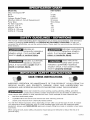
Model N o.
919-167801
Max. Developed HP
Bore
Stroke
Voltage-Single Phase
Minimum Branch Circuit Requirement
Fuse Type
Air Tank Capacity
Approx. Cut-In
Approx. Cut-out
SCFM @ 100 psig
SCFM @ 175 psig
7
4.134"
2.165"
240/60/1
30 amps
Time Delay
80
140
175
17.4
16.9
[-'f_'1al=lli'd [=_llJI m]=1mlI_I =[,.1..I m]=1alI _I InII[o]][[,1
This manual contains information that is important for you to know and understand. This information
relates to protecting YOUR SAFETY and PREVENTING EQUIPMENT
PROBLEMS. To help you
recognize this information, we use the symbols below. Please read the manual and pay attention to
these sections.
_lndicates
situation
which,
result in death
hazardous
_mminently hazardous
if not avoided, will
_lndicates
hazardous
which,
if not avoided,
death
or serious
which, if not avoided, _
result in
minor or moderate injury.
injury.
or serious
_Used
without the
safety alert symbol
indicates a potentially hazardous
situation which, if not avoided, may
result in property
damage.
a potentially
situation
could
a potentially
situation
result in
injury.
IhN _o] :i f;_ _bd[,.'9':_
al=Innk'dn
II_[,:,]i]_l]_o,]i][o_l
SAVE THESE INSTRUCTIONS
IMPROPER
SERIOUS
OPERATION
OR
INJURY
AND
AND
OPERATING
WARNINGS
MAINTENANCE
PROPERTY
OF
DAMAGE.
INSTRUCTIONS
THIS
PRODUCT
READ
BEFORE
_
_w
AND
USING
COULD
RESULT
UNDERSTAND
THIS
IN
ALL
EQUIPMENT.
Some dust created by power sanding, sawing, grinding, drilling, and other
construction activities contains chemicals known (to the State of California) to
cause cancer, birth defects or other reproductive harm. Some example of these chemicals are:
•
lead from lead-based
•
crystalline
•
arsenic and chromium
paints
silica from bricks and cement
and other masonry
from chemically-treated
products
lumber
Your risk from these exposures varies, depending on how often you do this type of work. To reduce
your exposure to these chemicals: work in a well ventilated area, and work with approved safety
equipment, always wear MSHA/NIOSH
approved, properly fitting face mask or respirator when using
such tools.
When using air tools, basic safety precautions
personal injury.
should always be followed
3-ENG
to reduce the risk of of
D26625
Save these instructions
Improper operation or maintenance of this product could result in serious injury and
property damage. Read and understand all warnings and operation instructions before
using this equipment.
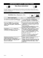
: V:YJ:I;] m]
WARNING:
Risk of Explosion or Fire
How To Prevent It
What Could Happen
It is normal for electrical contacts within
the motor and pressure switch to spark.
Always operate the compressor in a well
ventilated area free of combustible
materials,
If electrical sparks from compressor
come into contact with flammable
vapors, they may ignite, causing fire or
explosion.
If spraying flammable materials, locate
compressor at least 20 feet away from
spray area. An additional length of hose
may be required.
Store flammable
materials in a secure
location
Restricting any of the compressor
ventilation openings will cause serious
overheating and could cause fire.
gasoline, or solvent vapors.
away from compressor.
Never place objects against or on top
of compressor. Operate compressor in
an open area at least 12 inches away
from any wall or obstruction that would
restrict the flow of fresh air to the
ventilation openings.
Operate compressor in a clean, dry well
ventilated area. Do not operate unit
indoors or in any confined area.
Unattended operation of this product
could result in personal injury or
property damage. To reduce the risk of
fire, do not allow the compressor to
operate unattended.
D26625
Always remain in attendance
)roduct when it is operating.
with the
Always disconnect
electrical power by
moving pressure switch lever to the off
)osition and drain tank daily or after
each use.
4-ENG
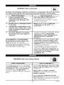
: V;YJ;I;1m_
WARNING:
Risk of Bursting
I_1
Air Tank: The following
conditions could lead to a weakening
in a violent tank explosion and could cause property damage
How To Prevent It
What Could Happen
Failure to properly drain
condensed water from tank,
causing rust and thinning of the
steel tank.
2.
3.
of the tank, and result
or serious injury.
Drain tank daily or after each use. If
tank develops a leak, replace it
immediately with a new tank or replace
the entire compressor.
Modifications
to the tank.
or attempted
repairs
Unauthorized
modifications
to the
Never drill into, weld, or make any
modifications to the tank or its
attachments.
unloader valve, safety valve, or any
other components which control
tank pressure.
4.
Excessive vibration
can weaken
The tank is designed to withstand specific
operating pressures. Never make
adjustments
or parts substitutions
to
alter the factory set operating
pressures.
the air tank and cause rupture or
explosion
ATTACHMENTS
For essential control of air pressure, you
must install a pressure regulator and
pressure gauge to the air outlet (if not
equipped) of your compressor. Follow the
equipment manufacturers
recommendation
and never exceed the
& ACCESSORIES:
Exceeding the pressure rating of air
tools, spray guns, air operated
accessories, tires, and other inflatables
can cause them to explode or fly apart,
and could result in serious injury.
maximum allowable pressure rating of
attachments. Never use compressor
to
inflate small low pressure objects such
as children's toys, footballs,
basketballs,
etc.
: V;YJ;I;t m_
WARNING:
Risk from Flying Objects
WHAT CAN HAPPEN
The compressed air stream can cause
soft tissue damage to exposed skin and
can propel dirt, chips, loose particles,
and small objects at high speed,
resulting in property damage or personal
injury.
HOW TO PREVENT IT
Always wear ANSI Z87.1 approved safety
glasses with side shields when using the
compressor.
Never point any nozzle or sprayer
toward any part of the body or at other
people or animals.
Always turn the compressor
oft and
bleed pressure from the air hose and tank
before attempting maintenance, attaching
tools or accessories.
5-ENG
D26625
I: V.._:l I'lm]
WARNING:
Risk of Electrical Shock
WHAT CAN HAPPEN
HOW TO PREVENT IT
Your air compressor is powered by
electricity. Like any other electrically
powered device, If it is not used properly
it may cause electric shock.
Never operate the compressor outdoors
when it is raining or in wet conditions.
Repairs attempted by unqualified
personnel can result in serious injury or
death by electrocution.
Any electrical wiring or repairs required
on this product should be performed by
authorized service center personnel in
accordance with national and local
electrical codes.
Never operate compressor with
protective covers removed or damaged.
Make certain that the electrical
Electrical Grounding: Failure to provide
adequate grounding to this product
could result in serious injury or death
from electrocution.
See grounding
circuit
to which the compressor is connected
provides proper electrical grounding,
correct voltage and adequate fuse
protection.
instructions.
I: V;Y_;I;t m]
WARNING: Risk to Breathing
WHAT CAN HAPPEN
HOW TO PREVENT IT
The compressed air directly from your
compressor is not safe for breathing.
The air stream may contain carbon
monoxide, toxic vapors, or solid
particles from the tank. Breathing these
contaminants can cause serious injury
or death.
Air obtained directly from the compressor
should never be used to supply air for
human consumption. In order to use air
produced by this compressor for
breathing, suitable filters and in-line
safety equipment
must be properly
installed. In-line filters and safety
equipment used in conjunction with the
compressor must be capable of treating
air to all applicable local and federal
codes prior to human consumption.
Sprayed materials such as paint, paint
solvents, paint remover, insecticides,
weed killers, may contain harmful vapors
and poisons.
Work in an area with good cross
ventilation. Read and follow the safety
instructions
provided on the label or
safety data sheets for the materials you
are spraying. Use a NIOSH/MSHA
approved respirator designed for use
with your specific application.
D26625
6-ENG
I: F.._:I I'lm]
WARNING:
Risk of Burns
WHAT CAN HAPPEN
HOW TO PREVENT IT
Touching exposed metal such as the
compressor head or outlet tubes, can
result in serious burns.
Never touch any exposed metal parts
on compressor during or immediately
after operation. Compressor
will remain
hot for several minutes after operation.
Do not reach around protective shrouds
or attempt maintenance until unit has
been allowed to cool.
I: F.._:I I'lm]
WARNING:
Risk from
Moving
Parts
WHAT CAN HAPPEN
[_
[_
HOW TO PREVENT IT
Moving parts such as the pulley, flywheel,
and belt can cause serious injury if they
come into contact with you or your
clothing.
Never operate the compressor with
guards or covers which are damaged or
removed.
Attempting
to operate compressor with
damaged or missing parts or attempting
to repair compressor with protective
shrouds removed can expose you to
moving par_s and can result in serious
injury.
Any repairs required on this product
should be performed by authorized
service center personnel.
I: F:_:I I'lm]
WARNING:
Risk
of Falling
WHAT CAN HAPPEN
HOW TO PREVENT IT
A portable compressor can fall from a table,
workbench or roof causing damage to the
compressor and could result in serious
injury or death to the operator,
Always operate compressor in a stable secure
position to prevent accidental movement of the
unit.Never operate compressor on a roof or
other elevated position. Use additional air
hose to reach high locations.
I: F.._:I I'lm]
WARNING:
RISK OF SERIOUS
INJURY OR PROPERTY
DAMAGE
WHEN TRANSPORTING
COMPRESSOR
[_]
(Fire, Inhalation, Damage to Vehicle Surfaces)
WHAT CAN HAPPEN
Oil can leak or spill and could result in
fire or breathing hazard; serious injury or
death can result. Oil leaks will damage
carpet, paint or other surfaces in vehicles
or trailers,
HOW TO PREVENT IT
Always place compressor on a
protective mat when transporting
to
protect against damage to vehicle from
leaks. Remove compressor from vehicle
immediately upon arrival at your
destination.
7_ENG
D26625
I: V;YJ;I;1m]
WARNING:
Risk of Unsafe
Operation
WHAT CAN HAPPEN
Unsafe operation of your air compressor
could lead to serious injury or death to
you or others,
D26625
HOW TO PREVENT IT
Review and understand all instructions
and warnings in this manual.
Become familiar with the operation and
controls of the air compressor.
Keep operating area clear of all persons,
pets, and obstacles.
Keep children away from the air
compressor at all times.
Do not operate the product when
fatigued or under the influence of
alcohol or drugs. Stay alert at all times.
Never defeat the safety features of this
product.
Equip area of operation with a fire
extinguisher.
Do not operate machine with missing,
broken, or unauthorized
parts.
8-ENG
Become familiar with these terms
before operating the unit.
CFM: Cubic feet per minute.
SCFM: Standard cubic feet per
minute; a unit of measure of air
delivery.
PSIG: Pounds per square inch
gauge; a unit of measure of pressure.
Code Certification:
Products that
bear one or more of the following
marks: UL, CUL, ETL, CETL, have
been evaluated by OSHA certified
independent safety laboratories and
meet the applicable Underwriters
Laboratories Standards for Safety.
Cut-In Pressure: While the motor is
off, air tank pressure drops as you
continue to use your accessory.
When the tank pressure drops to a
certain low level the motor will restart
automatically.
The low pressure at
which the motor automatically
restarts is called "cut-in" pressure.
Cut-Out Pressure: When an air
compressor is turned on and begins
to run, air pressure in the air tank
begins to build. It builds to a certain
high pressure before the motor
automatically shuts off - protecting
your air tank from pressure higher
than its capacity. The high pressure
at which the motor shuts off is called
"cut-out" pressure.
Branch Circuit: Circuit carrying
electricity from electrical panel to
outlet.
To Lock Out Power: Place a lock on
the line power switch so no one else
can turn on the power.
mLm.lljiJii_d
[o']_
m_
hour is considered misuse, because
the air compressor is undersized for
the required air demand. Maximum
compressor pumping time per hour is
30 minutes.
Air compressors should be operated
on not more than a 50% duty cycle.
This means an air compressor that
pumps air more than 50% of one
Accessories for this unit are available at the store the unit was purchased.
9-ENG
D26625
I_..'.,_".]
=iLv_
I :] i_"d
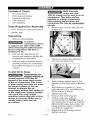
Contents
1
1
1
1
4
-
of Carton
Multi-Viscosity
motor oils, like
10W 30, should not be used in an air
compressor. They leave carbon
deposits on critical components,
thus reducing performance and
compressor life. Use air compressor
oil onlv.
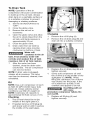
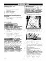
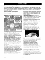
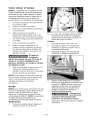
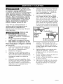
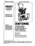
1. Remove the oil drain plug (B) and
washer (C).
Air Compressor
Parts bag containing:
Operator's Manual
Parts Manual
5/8" Washers
Tools Required
for Assembly
1 - 9/16" socket or open end wrench
1 - electric drill
Unpacking
1.
Remove all packaging.
It may be
necessary to brace
or support one side of the outfit
when removing the pallet because
the air compressor will have a
tendency to tip.
2. Remove and discard the (4)
screws and washers holding the
compressor to the pallet.
3.
2.
Obtain the drain plug extension
(D), from the parts bag.
3.
Apply thread sealant tape to the
threads of the drain plug extension
(D).
Assemble the washer (C), drain
plug extension (D), and drain plug
(B) as shown in Figure.
Tighten securely.
Remove the oil fill plug (A).
Fill the crankcase with the
recommended oil. NOTE: Use an
air compressor oil such as SAE-30
(API CG/CD heavy duty motor oil).
Under extreme winter conditions
use SAE-20 weight oil.
Replace the oil fill plug (A) and
tighten securely.
With the help of another person
carefully remove air compressor
from pallet and place on a level
surface.
To Add Oil To Pump
Compressors are
shipped without oil.
A small amount of oil may be
present in the pump upon receipt
of the air compressor. This is due
to plant testing and does not mean
the pump contains oil. Do not
attempt to operate this air
compressor without first adding oil
to the crankcase. Serious damage
can result from even limited
operation unless filled with oil and
broken in correctly. Make sure to
closely follow initial start-up
procedures.
4.
5.
6.
7.
8,
D26625
10-ENG
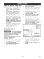
II__"hf;_ mlW:'Inl[o_
HOW TO SET UP YOUR
Location
UNIT
Place the air compressor
solid, level surface.
2.
Mark the surface using the holes
in the air compressor feet as a
template.
Drill holes in the surface for the
concrete anchors. Install
concrete anchors.
of the Air Compressor
•
Locate the air compressor in a
clean, dry, and well ventilated
area.
•
Locate the air compressor at
least 12" away from the wall or
other obstructions that will
interfere with the flow of air.
•
Locate the air compressor as
close to the main power supply
as possible to avoid using long
lengths of electrical wiring.
NOTE: Long lengths of electrical
wiring could cause power loss to
the motor.
•
1.
3.
4.
5.
The air filter must be kept clear
of obstructions which could
reduce air flow to the air
compressor.
Excessive Vibration
can weaken the air
tank and cause an explosion. The
compressor must be properly
mounted.
4 - Concrete anchors (not supplied)
4 - 3/8" Lag screw to fit concrete
anchors (not supplied)
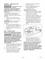
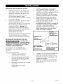
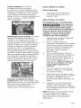
Line-up holes in surface with
holes in air compressor feet.
Place the (4) washers (not
supplied) between the floor and
air compressor feet. If needed,
solid shims may be placed
between the washers and floor to
evenly distribute weight on all
four feet. See next figure.
3/8" Lag
.....I
Screw
.............
I
(not
...................
_supplied)
5/8" Washer ....
_
I
(not suppliedi_.[
_
....................
I
Anchoring
of the Air
Corn pressor
The air compressor MUST be bolted
to a solid, level surface.
Hardware needed:
on on a
ShimUn-_
Washer
_
(not supplied)
Surface Line
Concrete Anchor
(not supplied)
6.
Place the (4) 3/8" lag screws
through the air compressor feet,
washers, shims, and into the
anchors.
7.
Torque 3/8" lag screws to 7-10
ft.-Ibs.
4 - 5/8" Washer shims (found in
parts bag, if needed)
11-ENG
D26625
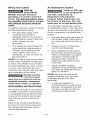
Wiring
Instructions
_
RISK OF
ELECTRICAL
SHOCK. Improper electrical
grounding can result in electrical
shock. The wiring should be done
by a qualified electrician to comply
with national and local electrical
codes.
A qualified electrician needs to knows
the following before wiring:
1.
2.
The amperage rating of the
electrical box should be
adequate. Refer to the product
specifications, found in the front
of this manual, for this
information.
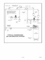
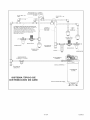
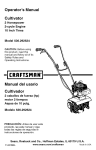
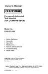
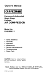
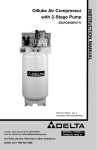
Air Distribution
Plastic or PVC pipe
is not designed for
use with compressed air.
Regardless of its indicated
pressure rating, plastic pipe can
burst from air pressure. Use only
metal pipe for air distribution lines.
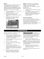
The next figure represents a typical
air distribution system. The following
are tips to remember when setting up
the air compressor's air distribution
system.
•
The supply line should have the
same electrical characteristics
(voltage, cycle, phase) as the
motor. Refer to the motor
nameplate, on side of motor, for
this information.
GROUNDING
Bury underground lines below
the frost line and avoid pockets
where condensation can gather
and freeze. Fill lines with air
pressure before covering to
make sure pipe joints are free
from leaks.
Install a flexible coupling
between the air discharge outlet
and main air distribution line to
allow for vibration.
NOTE: The shut-off valve is not
supplied with this unit. You must
purchsase the shut-off valve
separately.
•
INSTRUCTIONS
This product should be connected to
a metallic, permanent wiring system,
or an equipment-grounding
terminal
or lead on the product and comply
with national and local electrical
codes.
Refer to the product specification
found in the front of this manual for
the voltage and minimum branch
circuit requirements.
D26625
Use pipe that is the same size as
the air tank outlet. Piping that is
too small will restrict the flow of
air.
If piping is over 100 feet long,
use the next larger size.
NOTE: The wiring must be the same
as the motor nameplate voltage plus
or minus 10%. Refer to local codes
for recommended wire sizes, correct
wire size, and maximum wire run;
undersize wire causes high amp draw
and overheating to the motor.
Electrical wiring
must be located
away from hot surfaces such as
manifold assembly, compressor
outlet tubes, heads, or cylinders.
System
12-ENG
A separate regulator is
recommended to control the air
pressure. Air pressure from the
air tank is usually too high for
individual air driven tools.
FEEDER
LINES
SLOPE
AiR FLOW
FLEXIBLE
COUPLING
AiR DISCHARGE
VAEVE
LEG
AIR
COMPRESSOR
TYPmCAL COMPRESSED
AmR DmSTRIBIJTmON SYSTEM
DRAIN
COOK
VALVE
13-ENG
D26625
Know Your Air Compressor
READ THIS OWNER'S MANUAL AND SAFETY RULES BEFORE OPERATING
YOUR UNIT. Compare the illustrations with your unit to familiarize yourself with
the location of various controls and adjustments. Save this manual for future
reference.
Description
of Operation
Become familiar with these controls
before operating the unit.
Tank Pressure Gauge: The tank
pressure gauge indicates the reserve
air pressure in the tank.
Globe Valve (sold separately):
Opens and closes air discharge valve.
Turn knob counter-clockwise
to open
and clockwise to close.
Regulator (sold separately, not
shown): An air pressure regulator or
a separate air transformer which
combines the functions of air
regulation and/or moisture and dirt
removal is recommended for most
applications.
Drain Valve: The drain valve is
located at the base of the air tank
and is used to drain condensation at
the end of each use.
On/Auto/Off Switch: Turn this switch
ON to provide automatic power to the
pressure switch and OFF to remove
power at the end of each use.
Pressure Switch: The pressure
switch automatically starts the motor
when the air tank pressure drops
below the factory set "cut-in"
pressure. It stops the motor when the
air tank pressure reaches the factory
set "cut-out" pressure.
Safety Valve: If the pressure switch
does not shut off the air compressor
at its "cut-out" pressure setting, the
safety valve will protect against high
pressure by "popping out" at its
factory set pressure (slightly higher
than the pressure switch "cut-out"
setting).
D26625
Cooling System (not shown): This
compressor contains an advanced
design cooling system. At the heart of
this cooling system is an engineered
fan. It is perfectly normal for this fan
to blow air through the vent holes in
large amounts. You know that the
cooling system is working when air is
being expelled.
14-ENG
Air Compressor Pump (not shown):
Compresses air into the air tank.
Working air is not available until the
compressor has raised the air tank
pressure above that required at the
air outlet.
Air Intake Filter (not shown) This
filter is designed to clean air coming
into the pump. This filter must always
be clean and ventilation openings
free from obstructions, See
"Maintenance",
Check Valve: When the air
compressor is operating, the check
valve is "open", allowing compressed
air to enter the air tank. When the air
compressor reaches "cut-out"
pressure, the check valve "closes",
allowing air pressure to remain inside
the air tank.
How to Use Your Unit
How to Stop:
1.
Set the On/Auto/Off
"OFF",
lever to
Before Starting
Break-in Procedure
Check
Valve
Serious damage
may result if the
following break-in instructions are
not closely followed.
Pressure Release Valve: The
pressure release valve, located on the
side of the pressure switch, is
designed to automatically release
compressed air from the compressor
head and the outlet tube when the air
compressor reaches "cut-out"
pressure or is shut off. The pressure
release valve allows the motor to
restart freely. When the motor stops
running, air will be heard escaping
from this valve for a few seconds, No
air should be heard leaking when the
motor is running, or continuous
leaking after unit reaches "cut-out"
pressure.
This procedure is required before the
air compressor is put into service and
when the check valve or a complete
compressor pump has been
replaced.
1.
Make sure the On/Auto/Off
is in the "OFF" position,
2.
Recheck all wiring, Make sure
wires are secure at all terminals
connections, Make sure all
contacts move freely and are not
obstructed.
3.
Open the globe valve fully to
permit air to escape and prevent
air pressure build up in the air
tank during the break-in period.
NOTE: The shut-off valve is not
supplied with this unit. You
must purchase the shut-off
valve separately.
4.
Move the On/Auto/Off lever to
"ON/AUTO" position. The
compressor will start,
15-ENG
lever
D26625
5.
Run the
minutes.
valve is
minimal
tank.
6.
Check all air line fittings and
connections/piping
for air leaks
by applying a soap solution.
Correct if necessary. NOTE:
Minor leaks can cause the air
compressor to overwork,
resulting in premature breakdown
or inadequate performance.
7.
8.
compressor for 20
Make sure the globe
open and there is
air pressure build-up in
Check for excessive vibration.
Readjust or shim air compressor
feet, if necessary.
After 20 minutes, close the globe
valve. The air receiver will fill to
"cut-out" pressure and the motor
will stop.
Before
Each Start-Up:
1.
Place On/Auto/Off
"OFF".
2.
Close the globe valve.
3.
Attach hose and accessories.
NOTE: A regulator MUST be
installed when using accessories
rated at less than 175 PSI.
D26625
lever to
Too much air
pressure causes a
hazardous risk of bursting. Check
the manufacturer's maximum
pressure rating for air tools and
accessories. The regulator outlet
pressure must never exceed the
maximum pressure rating.
How to Start
1.
Turn the On/Auto/Off lever to
"AUTO" and allow tank pressure
to build. Motor will stop when
tank pressure reaches "cut-out"
pressure.
2.
When the tank pressure reaches
"cut-out" pressure open the
globe valve.
IMPORTANT: When using regulator
and other accessories refer to the
manufacturer-s instructions.
NOTE: Always operate the air
compressor in well-ventilated areas
free of gasoline or other combustible
vapors. If the compressor is being
used to operate a sprayer, DO NOT
place compressor near the spray
area.
16-ENG
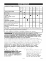
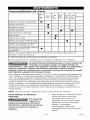
Customer
Responsibilities
Before Every Every Every Every
each 8
40
100
160
use
hours hours hours hours
Check Safety Valve
Every
500
Yearly
hours
•
Drain Tank
Check Oil
•
•
Change Oil
Unusual Noise and/or
Vibration
0 2
02
•
Air Filter
O1
Drive Belt-Condition
•
Motor Pulley/Flywheel alignment
•
Air compressor pump intake
and exhaust valves
Inspect air lines and fittings
for leaks
•
•
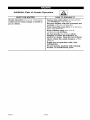
Head Bolts - Check the torques of the head bolts after the first five hours of operation.
1- more frequent in dusty or humid conditions
2- more frequent if humidity or operating conditions are extreme.
Unit cycles automatically when power is on. When
performing maintenance, you may be exposed to voltage
sources, compressed air, or moving parts. Personal injuries can occur.
Before performing any maintenance or repair, disconnect power source
from the compressor and bleed off all air pressure.
To ensure efficient operation and longer life of the air compressor outfit, a
routine maintenance schedule should be prepared and followed. The following
routine maintenance schedule is geared to an outfit in a normal working
environment operating on a daily basis. If necessary, the schedule should be
modified to suit the conditions under which your compressor is used. The
modifications will depend upon the hours of operation and the working
environment. Compressor outfits in an extremely dirty and/or hostile
environment will require a greater frequency of all maintenance checks.
NOTE: See "Operation"
To Check
Safety
section for the location of controls.
Before starting compressor, pull
the ring on the safety valve to
make sure that the safety valve
operates freely. If the valve is
stuck or does not operate
smoothly, it must be replaced
with the same type of valve.
Valve
If the safety valve
does not work
properly, over-pressurization may
occur, causing air tank rupture or
an explosion.
17-ENG
D26625
To Drain Tank
NOTE: Operation of the air
compressor will cause condensation
to build up in the air tank. Always
drain tank on a washable surface or
in a suitable container to prevent
damaging or staining surfaces.
1. Set the On/Auto/Off lever to
"OFF".
2.
3.
4.
5.
6.
Close the globe valve.
Remove the air tool or
accessory.
Open the globe valve and allow
the air to slowly bleed from the
air tank until tank pressure is
approximately 20 psi.
Close the globe valve.
Drain water from air tank by
opening drain valve (counterclockwise) on bottom of tank.
Changing
Water will
condense in the air
tank. If not drained, water will
corrode and weaken the air tank
causing a risk of air tank rupture.
7. After the water has been
drained, close the drain valve
(clockwise). The air compressor
can now be stored.
NOTE: If drain valve is plugged,
release all air pressure. The valve
can then be removed, cleaned, then
reinstalled.
1.
2.
Remove the oil fill plug (A).
Remove the oil drain plug (B) and
drain oil into a suitable container.
3.
Replace the oil drain plug (B) and
tighten securely
Sowly add compressor oil until
the oil level is in the middle of the
sightglass (C). NOTE: When
filling the crankcase, the oil flows
very slowly into the pump. If the
oil is added too quickly, it will
overflow and appear to be full.
4.
Oil
NOTE: Use a air compressor oil such
as SAE-30 (API CG/CD heavy duty
motor oil). Under extreme winter
conditions use SAE-20 weight oil.
NOTE: Crankcase oil capacity is
approximately 60 fluid ounces (1.8 I).
Checking
1. The oil level should be to the
middle of the sight glass (C).
2.
D26625
Overfilling with oil
will cause
premature compressor failure. Do
not overfill.
5.
If needed remove oil fill plug (A)
and slowly add oil until it reaches
the middle of the sight glass.
18-ENG
Replace oil fill plug (A) and
tighten securely.
Air Filter - Inspection
Replacement
and
Hot surfaces. Risk
of burn.
Compressor heads are exposed
when filter cover is removed.
Allow compressor to cool prior to
servicing.
A dirty air filter will not allow the
compressor to operate at full
capacity. Keep the air filter clean at
all times.
1. Remove the air filter cover.
2.
Remove the air filter from filter
cover.
5.
Remove the belt and replace
with a new one.
6.
See the "Adjust Belt Tension"
before tightening motor
mounting screws.
Adjusting
Belt Tension
1.
Slide motor into original position,
line the motor up with the mark
made earlier on saddle.
2.
Tighten two outside motor
mounting screws enough to hold
the motor in place for checking
pulley and flywheel alignment.
The belt should deflect 3/16" at
midway between the pulley and
the flywheel when a 5 pound
weight is applied at the midway
point.
3.
IMPORTANT: Do not operate the
compressor with the air filter
removed.
3. Place new air filter into filter
cover. Refer to the "Repair Parts"
for the correct part number.
4. Replace air filter cover and lock
into place.
Belt - Replacement
(Refer to the Outfit Parts Manual
for replacement belt part number.)
Serious injury or
damage may occur
if parts of the body or loose items
get caught in moving parts. Never
operate the outfit with the belt
guard removed. The belt guard
should be removed only when the
AIR compressor power is
disconnected.
1. Turn air compressor off, lock out
the power supply, and relieve all
air pressure from the air tank.
2.
Remove the belt guard.
3.
Mark pump position on saddle.
4.
Loosen the motor mounting
screws and slide the motor
4.
When proper belt tension is
achieved, tighten all four motor
mounting screws. See Parts
manual for torque specifications.
NOTE: Once the engine pulley has
been moved from its factory set
location, the grooves of the
flywheel and pulley must be aligned
to within 1/16" to prevent excessive
belt wear. Verify the alignment by
performing the following Pulley and
Flywheel - Alignment.
toward the air compressor.
19-ENG
D26625
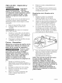
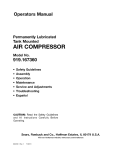
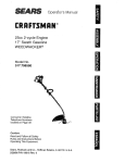
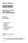
7.
Motor Pulley/Flywheel
Alignment
NOTE: Once the motor pulley has
been moved from its factory set
location, the grooves of the flywheel
and pulley must be aligned to within
1/16" to prevent excessive belt wear.
The air compressor flywheel and
motor pulley must be in-line (in the
same plane) within 1/16" to assure
belt retention within flywheel belt
grooves. To check alignment,
perform the following steps:
1. Turn air compressor off, lock out
the power supply, and relieve all
air pressure from the air tank.
2. Remove belt guard
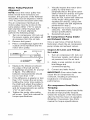
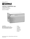
3. Place a straightedge against the
outside of the flywheel and the
motor drive pulley.
8.
9.
Visually inspect the motor drive
pulley to verify that it is
perpendicular to the drive motor
shaft. Points B1 and B2 of Figure
should appear to be equal. If
they are not, loosen the setscrew
of the motor drive pulley and
equalize B1 and B2, using care
not to disturb the belt alignment
performed in step 2.
Retighten the motor drive pulley
setscrew. See Parts manual for
torque specifications.
Reinstall belt guard.
Air Compressor
Pump
and Exhaust Valves
Intake
Once a year have a Trained Service
Technician check the air compressor
pump intake and exhaust valves.
Inspect Air Lines and Fittings
for Leaks
L
BELT
A1 t,2 IN_SU}_I
BI_ 8_ {w_u_)
4.
5.
6.
D26625
1.
Turn air compressor off, lock out
the power supply, and relieve all
air pressure from the air tank.
2.
Apply a soap solution to all air
line fittings and
connections/piping.
3.
Correct any leaks found.
_O'F Q,_:ULL,_Y
8TRNGHT
EDGE
Measure the distance between
the edge of the belt and the
straightedge at points A1 and A2
in figure. The difference
between measurements should
be no more than 1/16".
If the difference is greater or less
than 1/16" loosen the set screw
holding the motor drive pulley to
the shaft and adjust the pulley's
position on the shaft until the A1
and A2 measurements are within
1/16" of each other.
Tighten the motor drive pulley
set screw. See Parts manual for
torque specifications.
IMPORTANT: Even minor leaks can
cause the air compressor to
overwork, resulting in premature
breakdown or inadequate
performance.
Air compressor
Torquing
20-ENG
Head
Bolts -
The air compressor pump head bolts
should be kept properly torqued.
Check the torques of the head bolts
after the first five hours of operation.
Retighten if necessary. See Parts
manual for torque specifications.
Unit cycles
automatically
when
power is on. When doing
Maintenance, you may be exposed
to voltage sources, compressed air
or moving parts. Personal injuries
can occur. Before performing any
Maintenance or repair, unplug the
compressor and bleed off all air
pressure.
8,
Unscrew the check valve (turn
counterclockwise) using a 7/8"
open end wrench. Note the
orientation for reassembly.
6,
Using a screwdriver, carefully
push the valve disc up and
down. NOTE: The valve disc
should move freely up and down
on a spring which holds the valve
disc in the closed position, if not
the check valve needs to be
cleaned or replaced.
ALL MAINTENANCE AND REPAIR
OPERATIONS NOT LISTED MUST BE
PERFORMED BY TRAINED SERVICE
TECHNICIAN.
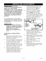
Before servicing:
position
nothing is
visible.
Unplug or disconnect electrical
supply to the air compressor.
Bleed tank of pressure.
Allow the air compressor to
cool.
To Replace
Valve
or Clean
In closed position
disc is visible.
7.
Clean or replace the check valve.
A solvent, such as paint or
varnish remover can be used to
clean the check valve.
8.
Apply sealant to the check valve
threads. Reinstall the check valve
(turn clockwise).
9.
Replace the pressure release
tube. Tighten nuts.
Check
1.
Release all air pressure from air
tank. See "To Drain Tank" in the
Maintenance section.
2.
Turn air compressor off, lock out
the power supply, and relieve all
air pressure from the air tank.
3.
Using an adjustable wrench
loosen outlet tube nut at air tank
and pump. Carefully move outlet
tube away from check valve.
4.
Using an adjustable wrench
loosen pressure relief tube nut at
air tank and pressure switch.
Carefully move pressure relief
tube away from check valve.
10. Replace the outlet tube and
tighten nuts.
11. Perform the Break-in Procedure.
See "Break-in Procedure" in the
Operation section.
21 -ENG
D26625
Motor
4.
This motor has a manual thermal
overload protector. If the motor
overheats for any reason, the
overload protector will shut off the
motor. The motor must be allowed to
cool down before restarting. To
restart:
IMPORTANT: If the overload
protector shuts the motor off
frequently, check for a possible
voltage problem. Low voltage can
also be suspected when:
1.
1.
The motor does not get up to full
power or speed.
2.
Fuses blow out when starting the
motor; lights dim and remain dim
when motor is started and is
running.
Place the On/Auto/Off
lever in
the Off position.
2.
Allow the motor to cool.
3.
Depress the red reset button on
the motor.
Place the On/Auto/Off lever in
the On/Auto postion to restart
the motor.
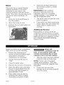
Additional
Service
Disassembly or service of the air
compressor beyond what is covered
in this manual is not recommended. If
additional service is required, contact
your nearest Authorized Warranty
Service Center.
Before you store the air compressor,
make sure you do the following:
1.
Review the "Maintenance"
section on the preceding pages
and perform scheduled
maintenance as necessary.
2.
Set the On/Auto/Off
"OFF".
7.
lever to
3.
Close the globe valve.
4.
Remove the air tool or accessory.
5.
Open the globe valve and allow
the air to slowly bleed from the
air tank until tank pressure is
approximately 20 psi.
6.
Drain water from air tank by
opening drain valve (counterclockwise) on bottom of tank.
D26625
Water will
condense in the air
tank. If not drained, water will
corrode and weaken the air tank
causing a risk of air tank rupture.
After the water has been drained,
close the drain or drain valve.
NOTE: If drain valve is plugged,
release all air pressure. The valve
can then be removed, cleaned, then
reinstalled.
8.
22-ENG
Protect the air hose from
damage (such as being stepped
on or run over).
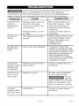
bd-'_o_!_oIo_
Performing repairs may expose voltage sources, moving
parts or compressed air sources, moving parts or
compressd air sources. Personal injury may occur. Prior to attempting any
repairs, unplug the air compressor and bleed off all air tank air pressure.
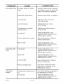
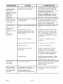
PROBLEM
Excessive tank
pressure (safety valv@
pops off.
CAUSE
CORRECTION
Pressure switch does not
shut off motor when
compressor reaches "cutout" pressure.
Pressure switch "cut-out"
too high.
Move On/Auto/Off lever to
the "OFF" position, if the
outfit does not shut off
contact a Trained Service
Technician.
Contact a Trained Service
Technician.
Air leaks at
fittings.
Tube fittings are not tight
enough.
Tighten fittings where air can
be heard escaping. Check
fittings with soapy water
solution. DO NOT
OVERTIGHTEN.
Air leaks at or
inside check
valve.
Check valve seat damaged.
A defective check valve
results in a constant air leak
at the pressure release valve
when there is pressure in the
tank and the compressor is
shut off. Replace check
valve. Refer the "To Replace
or Clean Check Valve" in the
"Operation" section.
Air leaks at
pressure switch
release valve.
(if equipped)
Defective pressure switch
release valve.
Contact a Trained Service
Technician.
Air leaks in air
tank or at air
tank welds.
Defective air tank.
Air tank must be replaced.
Do not repair the leak.
Air leaks
between head
and valve plate.
Leaking seal.
_
Do not
drill into,
weld or otherwise modify air
tank or it will weaken. The
tank can rupture or explode.
Contact a Trained Service
Technician.
23-ENG
D26625
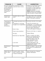
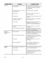
PROBLEM
CAUSE
CORRECTION
If there is an excessive amount
of pressure drop when the
accessory is used, adjust the
regulator as instructed in the
Operation section.
NOTE: Adjust the regulated
pressure under flow conditions
(while accesory is being used).
Pressure reading
on the regulated
pressure gauge
(if equipped)
drops when an
accessory is
used.
It is normal for "some"
pressure drop to occur.
Air leak from
safety valve.
Possible defect in safety
valve.
Operate safety valve manually
by pulling on ring. If valve still
leaks, it should be replaced.
Compressor is
not supplying
enough air to
operate
accessories.
Prolonged excessive use of
air.
Compressor is not large
enough for air requirement.
Decrease amount of air usage.
Hole in hose.
Check the accessory air
requirement. If it is higher than
the SCFM or pressure supplied
by your air compressor, you
need a larger compressor.
Check and replace if required.
Check valve restricted.
Remove and clean, or replace.
Air leaks.
Tighten fittings.
Restricted air intake filter
Clean or replace air intake
filter. Do not operate the air
compressor with the filter
removed. Refer to the "Air
Filter" paragraph in the
"Maintenance " section.
Loose belt.
Check belt tension, see
Adjusting Belt Tension in the
Maintenance section.
Restricted air
intake.
Dirty air filter.
Clean or replace. See Air Filter
paragraph in the Maintenance
section.
Safety Valve on
pump "pops"
out.
Pressure switch, check
valve, or pump could be
in need of servicing.
Have checked by a Trained
Service Technician.
D26625
24-ENG
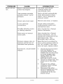
PROBLEM
Motor will not
run.
CAUSE
Motor overload protection
switch has tripped.
CORRECTION
Let motor cool off and
overload switch will
automatically reset.
Tank pressure exceeds
_ressure switch "cut-in"
%essure.
Motor will start automatically
when tank pressure drops
below "cut-in" pressure of
pressure switch.
Check valve stuck open.
Remove and clean, or replace.
Loose electrical
connections.
Check wiring connection
inside pressure switch and
terminal box area.
Possible defective motor
or starting capacitor.
Have checked by a Trained
Service Technician.
Paint spray on internal
motor parts.
Have checked by a Trained
Service Technician. Do not
operate the compressor in the
paint spray area. See
flammable vapor warning.
Pressure release valve on
)ressure switch has not
unloaded head pressure.
Bleed the line by pushing the
lever on the pressure switch to
the "off" position; if the valve
does not open, replace switch.
Fuse blown, circuit breaker
tripped.
1.
2.
3.
4.
25-ENG
Check fuse box for blown
fuse and replace as
necessary. Reset circuit
breaker. Do not use a fuse
or circuit breaker with
higher rating than that
specified for your
particular branch circuit.
Check for proper fuse. You
should use a time delay
fuse.
Check for low voltage
conditions and/or proper
extension cord.
Disconnect the other
electrical appliances from
circuit or operate the
compressor on its own
branch circuit.
D26625
PROBLEM
CORRECTION
CAUSE
Knocking Noise. Possible defect in safety
Excessive belt
wear.
Squealing
sound.
valve.
Operate safety valve manually
by pulling on ring. If valve still
leaks, it should be replaced.
Defective check valve.
Remove and clean, or replace.
Loose pulley.
Tighten pulley set screw,
145-165 in.-Ibs.
Loose flywheel.
Tighten flywheel screw
33-37 ft.-Ibs.
Compressor mounting
screws loose.
Tighten mounting
20-25 ft.-Ibs.
Loose belt.
Check belt tension, see
Adjusting Belt Tension in the
Maintenance section
Carbon build-up in pump.
Have checked by a Trained
Service Technician.
Belt to tight.
Check belt tension, see
Adjusting Belt Tension in the
Maintenance section.
Loose belt.
Check belt tension, see
Adjusting Belt Tension in the
Maintenance section.
Tight belt.
Check belt tension, see
Adjusting Belt Tension in the
Maintenance section.
Loose pulley.
Have checked by a Trained
Service Technician.
Pulley misalignment.
See Motor Pulley/Flywheel
Alignment paragraph in the
Maintenace section.
Compressor
oil.
See Oil-Checking paragraph in
the Maintenace section.
pump has no
Loose belt.
D26625
screws,
Check belt tension, see
Adjusting Belt Tension in the
Maintenance section.
26-ENG
27_ENG
D26625
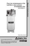
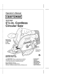
I:I I ;! [o.Zo]
LvJ-J;! _$',[o]_
i1 V:T_--_ Lv_
I
_40
J
32
_3!
38
D26625
28_ENG
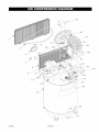
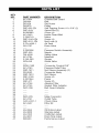
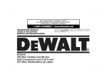
KEY
NO.
1
2
3
4
5
6
7
8
9
10
11
12
13
14
15
16
17
18
19
2O
21
22
23
24
25
26
27
28
29
30
31
32
33
35
36
37
38
39
40
41
42
43
44
45
46
47
PART NUMBER
AC-0434
D26434
SS-559
D25979
SSF-953-ZN
SSF-8131
91895680
AC-0433
Z-D26719
SSF-3140-ZN
SSF-8111 -ZN
Z-TA-4439-1
SS-2707
DESCRIPTION
Outside Belt Guard
Belt
Set Screw
Pulley
Self Tapping Screw 10 x 5/8" (2)
Speed Nut (2)
Screw (4)
Inside Guard Belt
Motor
Screw (4)
Nut Lock (4)
Air Tank
Drain Valve
Z-D20596
SSP-555
TIA-4200
AC-0764
Z-GA-360
SSV-6-B
Pressure Switch Assembly
Nipple
Safety Valve
Manifold
Gauge
Globe Valve
SSW-7482
AC-0763
SSP-7811
SS-8553
SSP-7812
SSF-3159
Z-D27044
SSF-577
AC-0756
AC-0755
DAC-306
Connector Conduit 3/8"
Pressure Relief Tube
Nut Sleeve Assembly (2)
Connector Body
Nut Sleeve
Screw (4)
Pump
Screw (2)
Adapter Filter
Gasket Filter Adapter
Belt Guard Adapter
DAC-225
AC-0751
CAC-4337-1
AC-0437
Male Connector
Outlet Tube
Check Valve
Filter Kit
LA-3355
LA-3266
LA-3105
LA-3027
D20420
Oil Notice Label
Warning Label
Craftsman Label
Drain Tank Label
Performance Label
29_ENG
D26625
I
i9
20
i
D26625
30-ENG
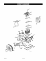
KEY
NO.
1
2
3
4
5
6
7
8
9
10
11
12
13
* 14
* 15
16
17
18
20
21
PART NUMBER
ABP-8226501
ABP-5961405
ABP-5950057
ABP-9053201
D25975
ABP-9022003
ABP-5940050
ABP-9101164
ABP-9162030
ABP-9004009
ABP-9110022
ABP-9163020
Z-ABP-9013013
ABP-8226502
ABP-8226503
ABP-8227093
ABP-8227092
ABP-5962000
ABP-5281100
ABP-9024011
DESCRIPTION
Hardware Kit
Head
Gasket Kit (Also includes Inner Valve Plate Gasket)
Oil Extension Tube
Flywheel
Sight Glass
Valve Plate Kit (Includes Inner Valve Plate Gasket)
Drain Plug Screw
Drain Plug Seal
Flywheel Washer
Flywheel Screw
Oil Seal
Shell Bearings (1 set)
HP Running Gear Kit
LP Running Gear Kit
HP Ring Kit
LP Ring Kit
Intercooler
Replacement Filter
Oil Fill Plug
NOT SHOWN
ABP-9049020
D26625
D20387
Intercooler Safety Valve
Owners Manual
Label, Specifications
*Includes piston, rings, piston pin, snap rings, oil dipper, split
bearings, locking nuts, and connecting rod.
31 -ENG
D26625
GARANTIA
CUADRO
..........................................................
DE ESPECIFICACIONES
DEFINIClONES
DE NORMAS
IMPORTANTES
INSTRUCCIONES
GLOSARIO
DE SEGURIDAD
29
.............................
DE SEGURIDAD
29
......................
29-34
..........................................................
ACCESORIOS
ENSAMBLADO
INSTALAClC)N
OPERACION
35
.......................................................
ClCLO DE SERVIClO
35
..................................................
35
.......................................................
36
.....................................................
37-38
......................................................
MANTENIMIENTO
SERVIClOS
28
......................................
Y REGULACIONES
ALMACENAJE
42-43
......................................
44-45
.......................................................
GUlA DE DIAGN(_STICO
NOTES/NOTAS
39-41
.................................................
DE PROBLEMAS
46
.............................
47-49
....................................................
MSTA DE PARTES
.................................................
COMO SOLICITAR
PIEZAS PARA REPARACION
GARANTIA COMPLETA
50-51
24-27
....................
POR UN AI_IO COMPRESOR
contratapa
DE AIRE
Si este compresor de aire fallara per defectos en materiales o mano de obra dentro del lapso de
un aSo a partir de la fecha de su compra, DEVUELVALOAL CENTRO DE REPARACIONES
SEARS MAS CERCANO DENTRO DE LOS ESTADOSUNIDOS, Y SEARS LO REPARARA,LIBRE
DE CARGO. Si se hubiese comprado a Orchard Supply Hardware, devuelvalo al comercio
Orchard mAs cercano y Orchard Io repararA, libre de cargo.
Si este compresor de aire fuese utilizado para prop6sitos comerciales o de alquiler, la garantia
solo tendra validez per noventa dfas a partir de la compra.
Esta garantia le otorga derechos legales especfficos, aunque usted podrA tener otros derechos
que poddan variar entre estados.
Sears, Roebuck and Co., Dept. 817WA,
D26625
32-SP
Hoffman Estates, IL 60179
[o..]uy;1
_,]::[o]I_,]::11=[,.-..]
-..,1=[o-]
I=1[o-7;Io-]
[o]_I=[,.-.,]
Modelo
N°
MAx. HP desarrollado
Didmetro interior
Carrera
Tensi6n monof_sica
919-167801
7
4,134 po (60,4mm)
2,165 po (34,3mm)
240/60/1
30A
Acci6n Retardada
Circuito minimo requerido
Tipo de Fusible
Capacidad de aire en el tanque
Presi6n de corte de entrada
Presi6n de corte de salida
80 Galones (113,6 litros)
140
175
SCFM @ 100 psig
SCFM @ 175 psig
17.4 Calibre de libras por pulgada cuadrada
16,9 Calibre de libra por pulgada cuadrada
I"] =1alI _I [o,][o]]_]#[,.']
I"] =1I][[o_
SEGURIDAD
Y
PREVENCION
DE
I"] ::1[.,."]_=']]i]
d I "7:1"]
PROBLEMAS
DEL
EQUIPO:
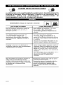
reconocimiento
de esta informaci6n, hemos utilizado los simbolos
Sirvase leer el manual y prestar atenci6n a dichas secciones.
, ..
,
Para
ayudar
mostrados
al
abajo.
Indica una situaci6n de
inminente
riesgo,
la
cual, si no es evitada, causarA la muerte
o lesiones serias.
,_,
Indicaunasituaci6n
potencialmente
peligrosa, la cual, si no es evitada, podria
resultar en lesiones menores o
moderadas.
Indica una
situaci6n
potencialmente
riesgosa, que si no es
evitada, podria resultar en la muerte o
lesiones serias.
Usado sin el simbolo
de seguridad de
alerta indica una situaci6n potencialmente
riesgosa la que, si no es evitada, podrfa
causar da_os en la propiedada.
I_vJ
"-.To]
;:in
IV__
_.inHi
::_"]II _.[,.'In
d;Lu[_*] [o]_.I:::[,."]
I=]=_'] ::[_uJ-'tl=7_*_
=]
_Algunos
tipos de aserrin creados por maquinas electricas de lijado, aserrado,
amolado, perforado u otras actividades de la construcci6n, contienen
rnateriales quimicos conocidos (en el Estado de California) como causantes de cancer, defectos de
nacimiento u otros dafios del aparato reproductivo. Algunos ejemplos de dichos productos quimicos son:
•
•
•
El plomo contenido en algunas pinturas con base de plomo
Sflice cristalizado proveniente de los ladrillos, el cemento y otros productos
Arsenico y cromo provenientes del tratamiento quimico dado a la madera
de albafiileria
Su riesgo a dichas exposiciones variara dependiendo de la frecuencia con la que usted realice
diferentes tipos de trabajo. Para reducir su exposicion a la accion de dichos agentes quimicos:
trabaje en zonas bien ventiladas, y hagalo con equipo de seguridad aprobado, use siempre protecci6n
facial o respirador MSHA / NIOSH aprobados cuando deba utilizar dichas herramientas.
AI utilizar herramientas neumaticas tambien deben tomarse
de reducir la posibilidad de riesgo de lesiones personales.
33-SP
precauciones
basicas de seguridad,
a fin
D26625
I]]_,,.']hj[i_uI_o,][o]_]_,.'__o]-'_L,1_hnl_
GUARDE
I,.]=lB'_I_[e-Iu]-'!l,.__,1
,,]
ESTAS INSTRUCCIONES
LA OPERACI(_N O EL MANTENIMIENTO INADECUADOS DE ESTE PRODUCTO
PODRIAN OCASIONAR SERIAS LESIONES Y DANOS A LA PROPIEDAD. LEA Y
COMPRENDA
TODAS
LAS ADVERTENCIAS
E INSTRUCCIONES
DE
FUNCIONAMIENTO ANTES DE UTILIZAR ESTE EQUIPO.
I'.] =1! It] ;[e]
ADVERTENCIA:
Riesgo
}_QUE PUEDE
OCURRIR?
de
explosi6n
o incendio
_,COMO
PREVENIRLO?
Para los contaotos el_otrioos es normal la
existencia de chispas entre el motor y el
interruptor a presi6n.
Opere siempre el compresor
en un sector
biee veetilado y libre de materiales
combustibles,
gasolina o emanaciones
de
solvente.
Si las chispas electricas provenientes del
compresor tomaran contacto
con
emanaciones
de materlAles
inflamables,
ellos podrian arder originando incendio o
explosi6n.
En un area de rociado de materiales
inflamables, ubique al compresor
por Io
menos a 6,1m (20 pies) de distancia
del ;_rea
de rociado. Podria requerirse una exteesi6n de
la manguera.
Almacene
ubicaci6n
los materiales
inflamables
en una
segura, alejados del compresor.
Restringir cualquiera de las aberturas de
ventilaciSn causar;_ un serio recalentamiento
y podria producir un incendio.
Jam&s coloque objetos apoyados o sobre el
compresor. Opere el eompresor en nn sector
abierto, pot Io menos a 30 cm (12 pulgadas)
alejado de cualquier pared u obetrueci6n que
restrinja el flujo de aire fresco alas aberturas de
ventilaci6n.
Opere el compresor en un sector limpio, seco, y
biee ventilado. No opere la unidad en
espacios cerrados o cualquier _rea
confinada.
Dejar desatenido este producto mientras el
mismo est;_ en funcionamiento
puede
resultar en lesiones personales o dafios a la
propiedad. Para reducir el riesgo de incendio,
no permita que el compresor opere
desatendido.
Mant_ngase siempre alerta cada vez que el
producto este funcionando.
D26625
Desconecte siempre el suministro el6ctrioo
moviendo la palanca conmutadora de
presi6n a la posici6n de apagado (off), y
drene el tanque diariamente o despu_s de
cada uso.
34-SP
I'.,1_ ! [_-"[*_
ADVERTENCIA:
TANQUE
DE
AIRE:
LAS
Riesgo
SIGUIENTES
DEBILITAMIENTO
DEL
A LA PROPIEDAD
O SERIAS LESIONES.
_QUI_
PUEDE
TANQUE,
de explosibn
I_1
CONDICIONES
Y DETERMINAR
PODRJAN,
SU EXPLOSION
OCURRIR?
_,C6MO
CAUSAR
VIOLENTA,
EL
DAI_IOS
PREVENIRLO?
1. Drenaje inadecuado del agua condensada
en el tanque, siendo la causa del 6xido
que reduce el espesor del tanque de
acero.
Drene el tanque diariamente o despu_s de
cada uso. Si el tanque genera una perdida,
reemplacelo inmediatamente
con un nuevo
tanque o reemplace el compresor completo.
2, Modificaciones
al tanque.
Jambs perfore, suelde, o efectOe modificaci6n
alguna al tanque o sus accesorios.
o intento de reparaciones
3. Modifioaciones
no autorizadas a la vblvula
de desoarga, vblvula de seguridad o
cualquier otro componente que controle
la presi6n del tanque.
El tanque esta diseSado para resistir presiones
operativas especfficas. Jam;_s efectt_e ajustes
o sustituya
partes que alteren las
regulaciones
de presi6n
originales
de
f;_brica.
4. La vibraci6n excesiva puede debilitar el
tanque de aire y causar su ruptura o
explosibn.
AGREGADOS
Y ACCESORIOS
El exceso a los valores de presibn
establecidos
para las herramientas
neumaticas, pistolas rociadoras, accesorios
activados por airs, cubiertas y otros objetos
inflables, puede causar su explosi6n o set
arrojados, pudiendo ocasionar serias lesiones.
Para un control esencial de la presion, debe
usted instalar un regulador y un medidor de
presi6n a la salida del aire de su compresor. (Si
no estuviese equipado) Siga las recomendaciones
de los fabricantes de su equipo y jambs exceda
los valores maximos de presion permitidos para
los accesorios. Jambs use el compresor para
inflar objetos que requieren poca o baja
presi6n, tales como juguetes para los niSos,
pelotas de f_tbol, pelotas de basquet, etc.
I",,]=1! [d ;[e]
ADVERTENCIA:
Riesgo
de objetos arrojados
}_QUE PUEDE OCURRIR?
por el aire.
&COMO
PREVENIRLO?
AI utilizar el compresor,
use siempre anteojos
de seguridad
ansi Z87.1 aprobados,
con
protecci6n
lateral.
El chorro de airs comprimido
puede causar
daSos sobre los tejidos blandos de la piel
expuesta, y puede propulsar suciedad,
astillas, particulas sueltas y pequei_os objetos a
alta velocidad, ocasionando daSos a la propiedad
o lesiones personales.
Jambs apunte ninguna boquilla o pulverizador
hacia partes del cuerpo, a otras personas o
animales.
Apague siempre el compresor
y purgue la
presi6n de la manguera del airs y del tanque,
antes de intentar el mantenimiento, el acople de
herramientas o accesorios.
35-SP
D26625
I:,,,1
_1! [,_ --[e]
ADVERTENCIA:
_QUE
PUEDE
Riesgo de descarga
OCURRIR?
eldctrica
_,C6MO
PREVENIRLO?
Su compresor de aire esta accionado per
electricidad. Cemo cualquier otto dispositivo
electrico impulsado electrieamente, si no se Io
utiliza adecuadamente,
podria causarle una
descarga el_ctrica.
Jamas opere el compresor a la intemperie
cuando esta Iloviendo o en condiciones de
humedad.
Las reparaciones intentadas por personal no
calificado podrian ocasionar serias lesiones
o la muerte por electrocucibn,
Cualquier conexi6n el_ctrica
o reparaci6n
requerida per este producto debe ser
efectuada pot personal autorizado
de los
servicentros
de acuerdo a los c6digos
electricos nacionales y locales.
CONEXION A TIERRA: Dejar de proveer una
adecuada conexi6n a tierra a este producto
podria ocasionar lesiones serias o la muerte
por electrocuci6n.
Ver instrucciones para la
puesta a tierra.
ADVERTENCIA:
_QUE
PUEDE
Nunca opere el compresor
o sus cubiertas removidas
sin sus defensas
o da_adas.
AsegOrese que el circuito el_ctrico al cual
estA conectado el compresor, suministra
apropiada conexibn a tierra, tensibn correcta
y una adecuada protecci6n
de fusibles.
Riesgo de inhalaci6n
OCURRIR?
_C6MO
PREVENIRLO?
El aire comprimido proveniente del compresor
no es sano para respirar. El chorro de aim
puede oontener monbxido de oarbono,
vapores t6xicos o parUculas s61idas
provenientes del tanque. La inhalacibn de
dichos oontaminantes
puede Ilegar a causar
serias lesiones o la muerte.
El aire obtenido directamente del compresor
jam_s deber_ ser utilizado para proveer aim
para consumo humano. Para poder utilizar el
aire producido por este compresor y hacerlo
resirable, deber_n instalarse un filtro adecuado
y un equipo de seguridad intercalado.
Los
filtros intercalados tanto como el equipo de
seguridad utilizado en conjunto con el
compresor, deber_n ser oapaces de procesar
el tratamiento
del aire de aouerdo a todos los
c6digos locales y federales,
previo al
consumo humano.
El rociado de materiales
tales como pintura,
solventes, removedores de pintura, insecticidas,
mata hierbas, contienen emanaciones
daSinas
y venenosas.
Trabaje en un ;_rea con buena ventilaci6n
cruzada. Lea y siga las instrucciones
de
seguridad
provistas en el r6tulo o en los datos
de las hojas de seguridad del material que est_
pulverizando.
Use el respirador
aprobado
NIOSH/MSHA
designado para utilizarse con su
aplieaci6n especffica.
D26625
36_SP
I:,,,1
=1! [,_ --[e]
ADVERTENCIA:
_,QUI_ PUEDE
RIESGO DE QUEMADURAS
OCURRIR?
_,C6MO
Tocar el metal expuesto tal como el cabezal
del compresor o los tubos de salida del escape,
puede ocaeienarle
serias quemaduras.
PREVENIRLO?
Jam_s toque partes de metal expueetas en el
compresor durante o inmediatamente
despues
de la operaci6n, el eempresor
permanecer;_
ealiente per varios minutos luego de la
operacion.
No Io cubra con fundas protectoras o intente
mantenimiento
hasta que la unidad haya
alcanzado su enfriamiento.
el
Id =1![d ;[e]
ADVERTENCIA:
_QUE
PUEDE
Riesgo de quemaduras
OCURRIR?
_,C6MO
Partes movibles tales come la polea, el
volante y la correa podrian ser la causa de
serias leeienes si elias entraran en contacto
con usted o sus ropas.
PREVENIRLO?
Nunca opere el compresor sin sue defensas
o sus cubiertas removidas o dafiadas.
Intentar
operar el compresor con sus partes
da_adae o faltantes,
e la reparacibn
del
oompresor
con sus proteociones
removidas,
puede exponerlo
a ueted a partee movibles,
que podrian resultar en lesiones serias.
Cualquier reparacion requerida por este
producto debe set efectuada
por personal
autorizado
de los servicentros.
Id =1![d ;[e]
ADVERTENCIA:
&QUle
PUEDE
Riesgo
de caida
OCURRIR?
&COMO
Un compresor portatil puede caerse de la
mesa, el banco de trabajo o del techo daSando
al compresor y pudiendo resultar en serias
lesiones o la muerte del operador,
PREVENIRLO?
Opere siempre el compresor en una posici6n
estable y segura a fin de prevenir el movimiento
accidental de la unidad. Jam_s opere el
compresor sobre un techo u otra posicibn
elevada, Utilice mangueras adicionales de aire
para alcanzar posiciones altas.
Id =1![d ;[o]
ADVERTENCIA:
compressor
Riesgo
de dahos
(Fuego, inhalaci6n,
&QUE
PUEDE
a la propiedad
daSo a la superficie
OCURRIR?
el aceite puede derramarse y ello podria
resultar en serias lesiones o la muerte debido al
riesgo de incendio o inhalacion. El derrame de
aceite dafia alfombras, pinturas u otras
superficies de vehl'culos o remolques,
al transportar
el
IB]
de vehiculos)
&C(_MO
PREVENIRLO?
Deposite el compresor sobre una alfombrilla
protectora
cuando Io transporte,
a fin de
proteger al vehiculo de perdidas por goteo,
Retire el compresor del vehl'culo inmediatamente
despues de su arribo al destino.
37_SP
D26625
ADVERTENCIA:
_,QUE PUEDE
Riesgo de operacibn
insegura
OCURRIR?
}_C6MO
La operacion insegura de su compresor de aire
podria ocasionarle
serias lesiones o la muerte
a usted u otros.
PREVENIRLO?
Revise y cornprenda todas las instrueciones y
advertencias contenidas en este manual.
Familiaricese con los m_todos de operacibn
control del compresor de aire.
Mantenga fibre la zona de operaciones de
persona alguna, animales domesticos y
obstAculos.
Mantenga alejados a los niSos del coxmpresor
de aire en todo momento.
No opere el producto
cuando se encuentre
fatigado o bajo la influencia del alcohol o
drogas. Est6 alerta en todo momento.
Jam;_s altere los elementos
este producto.
de seguridad
Equipe la zona de operaciones
extinguidor
de fuego.
No opere
faltantes,
D26625
38_SP
con un
la m;_quina si _sta tiene partes
rotas o no autorizadas.
de
y
Familiaricese con los siguientes t6rminos,
antes de operar la unidad:
CFM: (Cubic feet per minute) Pies cLibicos
por minuto.
SCFM: (Stardard cubic feet per minute)
Pies cQbicos estAndar por minuto; una
unidad de medida que permite medir la
cantidad de entrega de aire.
PSIG: (Pounds Per Square Inch Gauge) Presi6n manom_trica efectiva en libras por
pulgada cuadrada; una medida de la
entrega de aire.
Cbdigo de certificacibn:
Los productos
que usan una o m_s de las siguientes
marcas: UL, CUL, ETL, CETL, han sido
evaluados por OSHA, laboratorios
independientes certificados en seguridad,
y reLinen los estAndares suscriptos por
Underwriters Laboratories Standards for
safety.
Presibn minima de corte: Cuando el
motor est_ apagado, la presi6n del tanque
de aire baja a medida que usted continQa
usando su accesorio. Cuando la presi6n
del tanque baja al valor fijado en fAbrica
como punto bajo, el motor volverA a
arrancar automaticamente.
La presi6n
baja a la cual el motor arranca
automAticamente,
se llama presi6n
"minima de corte".
Presibn maxima de corte: Cuando un
compresor de aire se enciende y
comienza a funcionar, la presi6n de aire en
el tanque comienza a aumentar. Aumenta
hasta un valor de presi6n alto fijado en
f_brica antes de que el motor
autom_ticamente
se apague protegiendo
a su tanque de aire de presiones m_s
altas que su capacidad. La presi6n alta a
la cual el motor se apaga se llama presi6n
"mAxima de "coCce".
Ramal: Circuito el_ctrico que transporta
electricidad desde el panel de control
hasta el tomacorriente.
C6mo bloquear la alimentaci6n:
Coloque un cerrojo en el interruptor
de
alimentaci6n para impedir que alguien
pueda encenderlo."
[e][e]l[o] IB]=1[.-]_]_e][o]
Los compresores de aire deben ser
operados a no mAs del 50% de su ciclo
de servicio. Eso significa que si un
compresor de aire bombea aire per mAs
del 50% en una hora, estA considerado de
Los accesorios
pueden encontrarse
uso inadecuado, porque el compresor de
aire estA subdimensionado
para la
demanda requerida. 30 minutos por hora
debe ser el tiempo mAximo de bombeo de
un compresor.
en el comercio donde fue comprada
39-SP
la unidad.
D26625
Contenido
, ,_o
de la Caja
1 -
Compresor
1 -
Bolsa de piezas conteniendo
de aire
Manual del operador
1 -
Manual de piezas
4 -
Arandelas
de 5/8 plug.
Herramientas
ensamble
necesarias
para
_
Nosedebenusar
aceites de
viscosidad mt_ltiple como 10W30 en
ningtin compresor de aire. Estos
aceites dejan depbsitos de carbono en
componentes criticos, reduciendo el
rendimiento y la vida titil del compresor.
Sblo usar aceite para compresor de
aire.
Iosiguiente:
1 -
_
1.
Extraiga el tap6n del aceite (B) y la
arandela (C).
2.
Tome la extensi6n del tap6n de
drenaje de aceite (D), de la bolsa de
piezas.
3.
Aplique cinta selladora sobre los
filetes de rosca de la extensi6n del
tap6n de drenaje (D.
4.
Ensamble la arandela (C), la
extensi6n del tap6n (D) y el tap6n de
drenaje (B) tal como se muestra en la
Fig.
Ajuste firmemente.
Extraiga el tap6n de Ilenado de
aceite (A).
Llene la carcasa con el aceite
recomendado. NOTA: Use aceite para
compresor tipo SAE-30 (API CG/CD de
servicio pesado para motor). Para
condiciones extremas invernales use
aceite pesado SAE-2O.
Reponga el tap6n de Ilenado de
aceite (A) y ajuste firmemente.
el
1 - Ilave de tubo o de boca de 9/16 plug.
taladro el6ctrico
1 - el_ctricos
taladros
Desembalaje
1.
Extraiga todo el embalaje
Podra s.er
necesarlo
apuntalar o soportar un lado del equipo
al extraer la plataforma, porque el
compresor de aire tender_i a inclinarse.
2.
Extraiga y descarte los (4) tomillos y
arandelas que sujetan el compresor a
la plataforma.
3.
Con la ayuda de otra persona,
remueva cuidadosamente
el
compresor de aire de su plataforma
col6quelo sobre una plataforma
nivelada.
Para agregar
aceite
y
a la bomba
_Los
compresores
se envian sin
aceite. AI recibir el compresor de aire,
puede haber un poco de aceite en la
bomba. Esto se debe alas pruebas en
la fabrica y no significa que la bomba
tiene aceite. No intentar operar este
compresor de aire sin antes haberle
agregado aceite al carter. Pueden
ocurrir serios da_os, inclusive con
operaciones limitadas, si no se Ilena de
aceite y no se asienta correctamente.
Cerciorarse de seguir cuidadosamente
los procedimientos para el arranque
inicial.
5.
6.
7.
8.
D26625
40-sP
Ubicacibn
del compresor
1.
de aire
•
Instale el compresor de aire en una
zona limpia, seca y bien ventilada.
•
Instale el compresor
2.
de aire a una
3.
distancia no menor de 12 plug.
(30 cm) de la pared u otras
obstrucciones que pudiesen interferir
con el flujo del aire.
•
4.
Instale el compresor de aire Io m_s
cerca posible del sitio de
alimentaci6n el_ctrica, a fin de evitar
5.
el uso de largas extensiones de
cableado el_ctrico. NOTA: Las
extensiones el_ctricas demasiado
largas pueden causar una cafda de
tensi6n perjudicial para la
alimentaci6n del motor.
•
El filtro de aire debe mantenerse
libre
de obstrucciones que pudiesen
reducir el flujo del aire al compresor.
Anclaje
del compresor
Instale el compresor de aire sobre
una superficie s61ida y nivelada.
Marque la superficie utilizando como
plantilla, los orificios existentes en las
paras del compresor de aire.
Perfore la superficie, a fin de penetrar
los tarugos para anclaje en el cemento.
Coloque los tarugos en el cemento.
Haga coincidir la alineaci6n de los
orificios de la superficie, con el de las
paras del compresor de aire.
Coloque las (4) arandelas (no
suministrado) entre el piso y las patas del
compresor. Si fuese necesario, pueden
colocarse cu_as s61idas entre las
arandelas y el piso a fin de distribuir en
forma pareja el peso sobre las cuatro
patas. Vea la figura siguiente.
Arandela de
5/8"(no
de aire
Tornillo
tirafondo de
........3/8" (no
.................
|suministrado)
........
_
I
SUm inist rad o!. _i_[_[,_.........
]][[][h_
_
La vibracibn
excesiva puede
debilitar al tanque de aire y causar su
explosion. El compresor debe estar
montado adecuadamente.
dCeU
(no
El compresor de aire DEBE estar
abulonado a una superficie s61ida y
nivelada.
suministrado)
e s_uperficie
Tarugos para anclaje
en cemento (no
suministrados)
Elementos necesarios:
4 -
Tarugos para anclajes en
cemento (No Provistos)
4 -
Tornillos tirafondo de 3/8 plug.
capaces de Ilenar los tarugos
para anclaje en cemento (no
provistos)
4 -
6.
7.
Coloque los (4) tornillos tirafondo de
3/8 plug. (9 mm) a traves de las
patas del compresor de aire; de las
arandelas y cu_as, hasta Ilegar a los
tarugos de anclaje.
Aplique un torque de 7-10 pies-lbs.
sobre los tornillos tirafondo de 3/8
plug. (9 mm).
Arandelas 5/8 plug. (en la bolsa
de piezas)
Cu_as (en caso de ser
necesario)
41-SP
D26625
Instrucciones
el_ctrica
para
Sistema
la conexi6n
,
RIESGO DE
ELECTROCUCION.
Una
Antes de efectuar las conexiones, un
electricista calificado debe conocer Io
compresor
Utilice ca_o de la misma medida que
el de la salida del tanque de aire.
Una caSerfa demasiado angosta
restringirA el paso del aire.
•
Si la caheda tiene mAs de 100 pies
(30 m) de Iongitud, utilice la medida
inmediata superior.
•
Entierre la caSerfa por debajo de la
Ifnea de congelamiento y evite
huecos en los que la condensaci6n
se pudiese acumular y congelar.
EfectLie pruebas de presi6n antes de
cubrir la caderfa, a fin de asegurarse
que todas las uniones de la misma
se encuentran libres de fugas.
•
Se recomienda
corresponder al mismo voltaje indicado
sobre la placa de identificaci6n del motor
mas o menos 10%. Para informarse
acerca de las extensiones y calibres de
cable recomendadas y maxima extensi6n
del circuito, deberA referirse a los c6digos
locales; un circuito subdimensionado
origina una cafda elevada del amperaje y
un recalentamiento del motor.
de aire.
•
NOTA: La conexi6n electrica debe
la instalaci6n
de un
acoplamiento flexible, entre la salida
de descarga del aire y la Ifnea
principal de distribuci6n del mismo, a
fin de aliviar eventuales vibraciones.
NOTA: La vMvula de corte no se
suministra con esta unidad. Debe
La conexibn
eldctrica debe
estar ubicada fuera de superficies
calientes, tales como silenciadores de
escape, tubos de salida de
compresores
de aire, cabezales o
cilindros.
comprarse
•
per separado.
Se recomienda
la instalaci6n
de un
segundo regulador para el control de
la presi6n del aire. La presi6n de
salida del tanque es - usualmente demasiado alta para las herramientas
individuales de acci6n neumAtica.
PARA
A TIERRA
Este artefacto debe conectarse al terminal
metAlico de un sistema de cableado
permanente a tierra para equipos o al
terminal del artefacto.
La conexi6n a tierra est_ claramente
indicada sobre el compresor.
D26625
de aire. Las
siguientes son pautas para tener presente
al montar el sistema de distribuci6n del
Que la Ifnea de suministro el_ctrico
tenga id_nticas caracterfsticas
el_ctricas (voltaje, ciclos, fases) que
las del motor. Para obtener dicha
informaci6n deberA referirse a la
placa de identificaci6n del motor,
ubicada sobre el lateral del mismo.
CONECTAR
de aire
_
sistema tfpico de distribuci6n
deberA referirse a la hoja de
especificaciones
del manual de
piezas que se encuentra al principio
de este manual.
INSTRUCClONES
o
La siguiente imagen representa un
siguiente:
1.
Que el valor promedio del amperaje
en la caja el_ctrica sea el adecuado.
Para obtener dicha informaci6n
2.
de distribuci6n
Lostubosde
plastico o PVC
no han sido disefiados para usarlos con
aire comprimido. Independientemente
de Io que estd indicado como
especificaci6n de presi6n, las cafierias
de plastico pueden explotar debido a la
presibn del aire. Utilice solamente
carlos de metal para los ramales de
distribucibn.
conexi6n a tierra inadecuada
puede
ocasionar electrocuci6n.
Las
conexiones
deberan ser efectuadas
por
un electricista
calificado,
para cumplir
con los c6digos eldctricos nacional y
local.
,,
42_SP
PENDIENTE
DE LA
DE ALIMENTACION
COLUMNA
TUBERiA
CON
FLUJO
DE
DESECHOS
COMPRESION
DE AIRE
SISTEMA TiPmCO DE
DISTRIBUCI6N
DE AIRE
VALVU
43_SP
LA-GR_FO
DE
PURGA
D26625
Conozca su compresor
de aire
LEA ESTE MANUAL DEL PROPIETARIO Y SUS NORMAS
DE SEGURIDAD ANTES DE
OPERAR LA UNIDAD. Compare las ilustraciones contra su unidad a fin de familiarizarse
con la ubicaci6n de los distintos controles y regulaciones. Conserve este manual para
referencias futuras.
Descripci6n
Familiarfcese
de operaciones
Man6metro de la presi6n del tanque: El
man6metro que controla la presi6n del
tanque indica la reserva de presi6n del
tanque de aire.
con estos controles antes de
operar la unidad.
V;ilvula de asiento: Abre y cierra la
vMvula de descarga de aire. Gire la perilla
en sentido antihorario para abrir, yen
sentido horario para cerrar.
Regulador (vendido por separado, no
mostrado): Para la mayorfa de
aplicaciones se recomienda usar un
regulador de presi6n o un transformador
de aire separado que combine las
funciones de regulaci6n de aire y/o
eliminaci6n de humedad y tierra.
Valvula de drenaje (vendido por
separado): La vMvula de drenaje se
encuentra ubicada sobre la base del
tanque de aire y se usa para drenar la
condensaci6n al fin de cada uso.
Interrupter
On/Auto/Off:
Mueva este
interruptor a la posici6n ON para dar
contacto automAtico al interruptor de
presi6n, y OFF para interrumpir la energia
electrica al t_rmino del uso.
drenaje
Interrupter
de presi6n: El interruptor de
presi6n permite el arranque autom_tico
del motor cuando la presi6n del tanque
disminuye por debajo del valor de la
presi6n de conexi6n regulada en fabric&
El motor se detendr_ cuando la presi6n
del tanque alcance los valores de presi6n
de corte, regulado en fAbrica para su
desconexi6n.
Wilvula de seguridad: Si el interruptor de
presi6n dejara de cortar el suministro de
presi6n del compresor conforme a los
valores prefijados para la presi6n de corte,
la vAIvula de seguridad protegerA contra la
presi6n elevada, "saltando" de acuerdo a
los valores prefijados en fAbrica
(ligeramente superiores a los de presi6n
de corte de la Ilave interruptora.)
D26625
44-SP
Sistema de enfriamiento (no mostrado):
Este compresor contiene un sistema de
avanzada para el control de enfriamiento.
En el nLicleo de este sistema de
enfriamiento hay un ventilador
especialmente diser_ado. Resulta
perfectamente normal - para este
ventilador - soplar aire en grandes
cantidades a traves de los orificios de
ventilaci6n. De tal manera se podrA saber
que el sistema de enfriamiento trabaja
cuando el aire esta siendo expelido.
Bomba de compresibn del aire (no
mostrada): Comprime el aire dentro del
tanque. El aire de trabajo no se encuentra
disponible hasta que el compresor haya
alcanzado a Ilenar el tanque hasta un nivel
de presi6n por encima del requerido para
la salida del aire.
C6mo utilizar su unidad
Valvula reguladora: Cuando el
compresor de aire se encuentra
funcionando, la v_lvula reguladora esta
"abier_a", permitiendo la entrada del aire
comprimido al tanque de aire. Cuando el
nivel de presi6n del tanque alcanza el
punto de "corte", la v_lvula reguladora "se
cierra", reteniendo la presi6n del aire
dentro del tanque.
C6mo detenerla:
1.
Coloque la posici6n de la Ilave
interruptora On/Auto/Off en la
posici6n "OFF".
Antes de poner en marcha
Procedimiento
para el asentamiento
_Si
las siguientesno
instrucciones
fuesen seguidas estrictamente, podr_n
ocurrir serios dahos.Este procedimiento es
necesario antes de poner en servicio al
compresor de aire, y cuando la v_lvula
reguladora o la bomba completa del
compresor haya sido reemplazada.
Valvula aliviadora de presibn: La vAIvula
aliviadora de presi6n se encuentra
ubicada en el costado del interruptor de
presi6n; ha sido disefiada para liberar
automAticamente el aire comprimido de la
cabeza compresora y el tubo de salida,
cuando el compresor de aire alcanza la
presi6n de "corte" o es apagado. La
v_lvula aliviadora de presi6n permite el
arranque libre del motor. Cuando el motor
se detiene, deberia escucharse el escape
del aire a trav_s de dicha vAIvula durante
unos segundos. No debe escucharse
escape alguno mientras el motor estA en
march& ni p_rdidas continuas una vez
que se alcanz6 la presi6n "de corte".
1.
Aseg_rese que la palanca On/Auto/Off
est_ en la posicion "OFF".
2.
Vuelva a verificar todas las
conexiones. AsegL_rese que los cables
est6n firmes en todas los terminales
de sus conexiones. AsegQrese que
todos los contactos se muevan
libremente y que no existan
obstrucciones.
3.
Abra completamente la v_lvula de
asiento a fin de permitir el escape del
aire y prevenir la acumulaci6n de
presi6n de aire dentro del tanque de
aire, durante el periodo de
asentamiento. NOTA: La v_lvula de
oorte no se suministra con esta
unidad. Debe comprarse
separado.
Filtro para la entrada del aire (no
mostrado) Este filtro est_ disefiado para
limpiar el aire que entra a la bomba. Dicho
filtro debe estar siempre limpio y los
orificios de ventilaci6n libres de
obstrucciones. Vea "Mantenimiento".
pot
4.
Mueva la palanca On/Auto/Off a la
posiciOn 'ON/AUTO". El compresor
se pondra en march&
5.
Haga funcionar el compresor durante
20 minutos. AsegQrese que la v_lvula
de asiento est6 abierta y que la
presiOn de aire dentro del tanque sea
minima.
Aplicando una solucion jabonosa,
verifique todas las uniones de las
caflerias y las conexiones / caflerias a
fin de detectar fugas de aire. Corrija si
fuese necesario.
NOTA: P6rdidas menores pueden causar
una carga adicional de trabajo al
compresor, dando come resultado su
rotura prematura o una performance
inadecuada.
45-SP
D26625
7.
Verifique la existencia de vibraci6n
excesiva. Reajuste o acute el pie del
compresor, si ello fuera necesario.
8.
Luego de 20 minutos, cierre la
v_lvula de asiento. El aire recibido
elevarA la presidn hasta el punto de
"presidn de corte", y ello harA
detener al motor.
El compresor
usado.
Como poner en marcha
1.
valor de presi6n "de corte" del tanque.
2.
estarA ahora listo para ser
Coloque el interruptor On/Auto/Off en la
posicidn "OFF" y cierre el regulador de
aire.
2.
Cierre la vAIvula de asiento.
3.
Conecte la manguera y accesorios.
NOTA: Cuando se utilicen accesorios
NOTA: Opere siempre el compresor de aire en
d_reasbien ventiladas, libres de gasolina u otras
emanaciones combustibles. Si el compresor
sera utilizado para utilizar un rociador, NO Io
coloque en las cercanias de la zona de
rociado.
especificados para menos de 175
PSI deberA instalarse un regulador.
Demasiada
presion de aire
podr_ set la causa de riesgo de explosi6n.
Verifique los valores de m_xima presi6n
dados por el fabricante de las herramientas
neum_ticas y los accesorios. La presi6n de
salida del regulador jamds debe exceder los
valores de maxima presi6n especificados.
D26625
Cuando la presi6n del tanque
alcanza el valor de "presi6n de corte"
se abre la vAlvula de asiento.
IMPORTANTE: AI utilizar un regulador y
otros accesorios, refierase alas
instrucciones del fabricante.
Antes de cada puesta en marcha
1.
Mueva la palanca On/Auto/Off a la
posici6n "AUTO" y deje que se
incremente la presi6n del tanque. El
motor se detendrA una vez alcanzado el
46-SP
ResponsabUidades
del cliente
I
Antes
de
cada
USO
Verifique la v_lvula de seguridad
ICada
Cada 8 40
horas
horas
Cada
160
horas
Cada
500 Anualmente
horas
•
Drenaje del tanque
•
Verifique el aceite
•
Cambio de
Cada
100
horas
aceite
•2
•2
Ruido inusual y/o vibraci6n
•
Filtro de aire
•_
Estado de la correa
•
Alineado de la polea/volante del motor
•
V_.lvulas de entrada y escape de la
bomba del compresor de aire
Inspecci6n de eventuales fugas en
las caherfas de aire y las
conexiones.
•
•
Pernos del CabezaI-Verificar el torque de los pemos del cabezal despu6s de las
3rimeras 5 horas de operaci6n.
1- M_s frecuente en condiciones
2- Plus fr6quemment
,
,.
o
si I'humidit6
polvorientas
o h0medas.
ou les conditions
d'utilisation
sont extr6mes.
,
La unidad funciona automaticamente
en cicloe cuando esta
conectada a la energia. Cuando se realizan trabajos de
mantenimiento,
usted puede estar expuesto a fuentes de voltaje, aire comprimido o
piezas en movimiento. Pueden ocurrir lesiones personales. Antes de realizar
cualquier trabajo de mantenimiento o reparacibn, desconecte la fuente de energia
del compresor y purgue toda la presi6n de aire.
Para asegurar una operaci6n eficiente y una vida Qtil m_s prolongada del equipamento
de su compresor de aire debe prepararse y seguirse un programa de mantenimiento de
rutina. El siguiente programa de mantenimiento de rutina estA dise_ado para un equipo
funcionando diariamente en un ambiente normal de trabajo. Si fuese necesario, el
programa deberA ser modificado para adaptarse alas condiciones bajo las cuales se
usa su compresor. Las modificaciones dependerAn de las horas de operaci6n y del
ambiente de trabajo. Los equipos de compresi6n funcionando en un ambiente
sumamente sucio y hostil requerirAn mayor frecuencia de todas las verificaciones de
mantenimiento.
NOTA: Vea en la secci6n
C6mo
verificar
"Operaci6n"
la valvula
para la ubicaci6n de los controles.
de
1,
seguridad
Antes de poner en marcha el motor,
tire del anillo de la vAIvula de
seguridad para confirmar la
seguridad de que la misma opera
libremente, si la vAIvula quedase
trabada o no trabajara
c6modamente, deber_ ser
Si la valvula de
seguridad no
trabaja adecuadamente,
ello podra
determinar la sobrepresibn del tanque,
creando el riesgo de su ruptura o
explosi6n.
reemplazada
vAIvula.
47-SP
por el mismo tipo de
D26625
Cbmo drenar el tanque
NOTA: La operaci6n del compresor de aire
causa condensaci6n que se acumula dentro
del tanque de aire. Drene siempre el tanque
sobre una superficie lavable o dentro de un
contenedor apropiado, con el objeto de
prevenir da_os o el manchado de superficies.
1.
2.
Coloque la palanca On/Auto/Off
la posicidn "OFF".
Cierre la vAIvula de asiento.
en
3.
Remueva la herramienta
o el accesorio.
neumAtica
4.
Abra la v_lvula de asiento y
lentamente deje purgar el aire del
tanque de aire, hasta que la presi6n
del mismo Ilegue aproximadamente
a 20 PSI.
5.
Cierre la vAIvula de asiento.
6.
Drene el agua centenida en el
tanque de aire, abriendo la vAIvula
de drenaje ubicada en la base del
tanque (en sentido contrario alas
agujas de reloj).
2.
En case de necesidad quite el tap6n
de Ilenado de aceite (A) y agregue
lentamente aceite hasta alcanzar la
mitad del visor de vidrio.
Cambio
1.
Extraiga el tap6n del aceite (A).
2.
Extraiga del tap6n de drenaje del
aceite (B) y drene el aceite en un
recipiente adecuado.
3.
Reponga el tap6n de drenaje del
aceite (B) y ajQstelo firmemente.
4.
Agregueaceite lentamenteal compresor
hasta que el nivel alcance la mitad del visor
de vidrio (C). NOTA:AI Ilenar el carter del
cigQeSal,el aceite fluye muy lentamente
dentro de la bomba, Si el aceite fuese
agregado rapidamente rebalsara y
aparentara haberse Ilenado.
El agua se
condensa
dentro del tanque de aire. Si no se la
drena, Io corroera debilitando sus
paredes, poniendo en riesgo la ruptura
del tanque de aire.
7.
Una vez drenada el agua, cierre la
vAIvula de drenaje (girando en
sentido horario). Ahora el compresor
de aire podrA ser guardado.
NOTA: Si la vAIvula de drenaje fuera del
ripe enchufe, elimine toda la presidn de
aire. La vAIvula podrA entonces ser
extraida, limpiada y finalmente
reinstalada.
Aceite
NOTA: Use aceite para compresor de aire
tal come aceite para motor para servicio
pesado SAE-30 (API CG/CD). Bajo
extremas condiciones de invierno use
_
aceite pesado SAE-20. NOTA:La capacidad
de aceite del carter del cig0eSales de
aproximadarnente60 onzas fluidas (1,8 litros).
Verificaci6n
1.
D26625
Sobrepasar
el
nivel de aceite
causar_ la falla prematura del
compresor. No exceda su Ilenado.
5.
El nivel de aceite deber_ Ilegar a la
mitad del visor de vidrio (C).
48-SP
Reponga el tap6n del aceite (A)y ajustelo
firmemente.
Filtro de Aire - Inspeccibn y
reemplazo
_
5.
Retire la correa y reempl4cela
una nueva.
6.
Vea "Regulaci6n de la tensi6n de la
correa" antes de ajustar los tornillos
montantes del motor.
Superficies
calientes.
Riesgo de quemaduras.
Las cabezas
del compresor estan expuestas cuando
se retira la cubierta del filtro. Deje
enfriar al compresor antes de darle
servicio.
Regulaci6n
1.
Retire la tapa del filtro de aire.
Extraiga el filtro de aire de la
cubierta.
1.
Deslice el motor a su posici6n
original; alin6elo con la marca
efectuada antes sobre el montante.
2.
Ajuste los dos tornillos exteriores del
motor, Io suficiente para sostener a
este en posici6n hasta verificar la
alineaci6n de la polea y el volante.
3.
La correa debe flexionarse 4,8 mm
(3/16 plug.) en el punto medio de la
distancia entre la polea y el volante,
cuando, en dicho punto, se le aplica
una fuerza de 2,3 Kg (5 libras).
4.
Una vez Iograda la tensi6n adecuada,
ajuste los cuatro tornillos montantes.
Vea el Manual de partes para
informarse acerca de las
especificaciones
de torque.
IMPORTANTE: No opere el compresor
sin su filtro de aire.
3.
de la
Correa
Un filtro de aire sucio no permitir_ que el
compresor opere a plena capacidad.
Mantenga el filtro de aire limpio en todo
memento.
2.
de la Tensibn
por
Instale un nuevo filtro de aire dentro
la cubier_a del filtro. Para obtener el
nL_mero de pieza correcto. Refi@ase
a "Piezas de reparaci6n"
4.
Reponga la cubierta del filtro de aire
y sujetela en su sitio.
Correa - Reemplazo
(Referirse
unidad
parte
al manual
para
obtener
de la correa
de partes
de la
el numero
de
de repuesto.)
Pueden ocurrir
serios da_os
personales si las piezas movibles
atrapan partes del cuerpo o articulos
sueltos. Nunca opere el equipo sin el
cobertor de la correa. Sblo debe
quitarse el cobertor de la correa
cuando se desconecta el compresor
aire.
NOTA: Una vez que la polea del motor
ha sido movida, a partir de su
instalacibn original de fabrica, las
ranuras del volante y la polea deben
alinearse dentro un rango de variacibn
de 1/16 plug. (1,6 mm), para prevenir un
excesivo desgaste de la correa.
Verifique la alineacibn ejecutando el
siguiente procedimiento de alineacibn
polea-volante.
de
1.
Apagar el cornpresor de aire,
desconectar el suministro el_ctrico, y
liberar toda presi6n de aire dentro del
tanque.
2.
Extraiga la protecci6n
3.
Marque la posici6n
sobre el montante.
4.
Afloje los tomillos montantes del
motor y deslice este hacia el
compresor.
de la correa.
de la bomba
49-SP
D26625
Polea
y volante
8.
- Alineaci6n
NOTA:Una vez que la polea del motor ha
sido movida, punto de su instalaci6n
original de f_brica, las ranuras del volante
y la polea deben alinearse dentro un
rango de variaci6n de 1/16 plug. (1,6 mm),
para prevenir un excesivo desgaste de la
correa.
El volante del compresor de aire y la polea
del motor deben estar en linea (en el
mismo piano) dentro de una variaci6n de
1/16 plug. (1,6 mm), para asegurar la
retenci6n de la correa dentro de las
ranuras del volante. Para verificar la
alineaci6n ejecute los siguientes
1.
2.
3.
V_lvulas
bomba
Inspecci6n
pasos:
Al A;_(MED_#A)
_1_ 82 (VISUAL)
de la
de aire
de aire
para detectar
fugas
1.
Apagar el compresor de aire,
desconectar el suministro el6ctrico, y
liberar toda presi6n de aire dentro
del tanque.
2.
Aplique una soluci6n jabonosa a
todos los acoplamientos de aire y
las conexiones / cafierfas.
3.
Corrija cualquier p6rdida encontrada.
DEL r_OTOR
IMPORTANTE: Incluso p6rdidas menores,
pueden causar una carga adicional de
trabajo al compresor, dando como
resultado su rotura prematura o una
performance inadecuada.
BORDE
RECTO
Mida la distancia entre el borde de la
correa y la regla, en el punto A1-A2
de la figura ser. La diferencia entre
las mediciones no debe mayor que
1/16 plug. (1,6 mm).
Si la diferencia es mayor o menor
que 1/16 plug. (1,6mm), afloje los
tornillos de fijaci6n que sostienen la
polea de empuje del motor al eje, y
ajuste la polea sobre este hasta que
las medidas de A1 y A2 se
encuentren comprendidas entre
1/16 plug. (1,6 mm).
Ajuste los tornilios de fijaci6n de la
polea del motor. Vea el Manual de
partes para informarse de las
especificaciones
de torque.
Verifique vieualmente que la polea de
empuje del motor este perpendicular al
eje del mismo. Los puntos B1 y B2 de ia
figura deben parecer iguales. Si aef no
fuera, afioje el juego de tomillos de
fijaci6n de la polea de empuje del motor
e iguale B1 y B2, teniendo cuidado de no
alterar la alineaci6n de la correa
Tornillos
de aire.
del cabezal
del compresor
- Torque
Los tornillos del cabezal del compresor de
aire deben mantenerse debidamente
ajustados. Verifique el torque de los
tornillos del cabezal luego de las primeras
cinco horas de operaci6n. ReajQstelos si
fuese necesario. Vea el Manual de partes
para informarse de las especificaciones
de torque.
ejecutada en el paso 2.
D26625
y salida
de las ca_erias
y las conexiones
Coloque una regla contra el lado
exterior del volante y la polea de
empuje del motor.
_OLEA
de entrada
del compresor
Una vez al afio haga que un t6cnico
capacitado de servicio inspeccione las
vAIvulas de entrada y salida de la bomba
del compresor de aire.
Apagar el compresor de aire,
desconectar el suministro el6ctrico, y
liberar toda presi6n de aire dentro
del tanque.
Remueva la defensa de la correa.
_ORREA
4.
9.
Reajuste los tornillos de fijaci6n de la
polea de empuje del motor. Vea el
Manual de partes para informarse de
las especificaciones
de torque.
Reinstale la defensa de la correa.
50-SP
,
,_
o
_
Launidadcicla
automaticamente
Desenrosque la vMvula de retenci6n
girAndola hacia la izquierda usando
una Ilave de boca de 7/8 plug. (22
mm). Tome nota de la orientaci6n
para volverla a ensamblar.
en cuanto la energia eldctrica es
conectada. AI efectuar el mantenimiento,
usted quedara expuesto a tensibn viva,
aire comprimido o partes en movimiento.
Debido a tales circunstancias, podrian
ocurrirle lesiones personales. Antes de
efectuar mantenimiento o reparacibn
alguna, desenchufe el compresor y
purgue cualquier presi6n de aire.
Usando un destornillador, empuje
con cuidado el disco de la vMvula
hacia arriba y hacia abajo. NOTA: El
disco de la vMvula debe moverse
libremente hacia arriba y hacia abajo
sobre un resorte que detiene el disco
de la v_.lvula en la posici6n cerrada.
Si no Io hace, la vAIvula de retenci6n
necesita ser limpiada o reemplazada.
TODO TIPO DE MANTENIMIENTO Y
OPERACIONES DE REPARACION NO
MENCIONADOS, DEBERA,N SER
EFECTUADOS POR PERSONAL TECNICO
ESPECIALIZADO.
•
Antes de dar
(servicio):
Desenchufe o desconecte el
suministro eldctrico al compresor
de aire.
•
Purgue la presibn del tanque.
•
Deje enfriar al compresor
•
Deje enfriar al compressor
Para reemplazar
de retenci6n
o limpiar
En posici6n cerrada
el disco es visible
de aire.
de aire.
7.
Limpie o reemplace la vMvula de
retenci6n. Un solvente, tal como un
removedor de pintura o de barniz
puede usarse para limpiar la vMvula
de retenci6n.
8.
Aplique sellador alas roscas de la
vAIvula de retenci6n. Vuelva a
instalar la vAIvula de retenci6n (gire a
la derecha).
Vuelva a instalar la tuberia de alivio de
presi6n. Ajuste las tuercas.
la valvula
1.
Libere toda la presi6n del tanque de
aire. Vea "C6mo Drenar el Tanque"
en la secci6n "Mantenimiento".
2.
Desenchufe
3.
Utilizando una Ilave regulable, afloje la
tuerca del tubo de salida del tanque de
aire y la bomba. Retire cuidadosamente
la tuberia de salida de la vMvula de
retenci6n.
4.
En posici6n
abierta
nada es
visible
el equipo.
9.
Utilizando una Ilave regulable, afloje
la tuerca del tubo aliviador de presi6n
en el tanque de aire y el interruptor
de presi6n. Retire cuidadosamente
la
tuberla de alivio de presi6n de la
v_lvula de retenci6n.
51-SP
10.
Vuelva a instalar la tuberfa de salida y
ajuste las tuercas.
11.
Ejecute el procedimiento de puesta
en marcha. Vea Procedimiento de
Puesta en Marcha" en la secci6n
"Operaci6n".
D26625
Motor
NOTA: Si el protector de sobrecarga
apaga el motor con mucha frecuencia,
verifique si hay algt_n posible
Este motor tiene un protector manual de
sobrecarga t_rmica. Si el motor se
sobrecalienta por cualquier motivo, el
protector de sobrecarga apaga el motor.
Debe permitirse que el motor enfrie antes
de volverlo a arrancar de la siguiente
forma:
1.
2.
3.
4.
Mover la palanquita de On/Auto/Off
la posici6n de Off.
Permitir que el motor se enfrie.
problema de voltaje. Tambien se puede
sospechar de
bajo voltaje cuando:
a
Presionar el bot6n rojo de
Reinicializaci6n (Reset) que estA en el
motor.
Para arrancar el motor mover la
palanquita de On/Auto/Off a la
posici6n de On/Auto.
1.
El motor no alcanza toda su potencia
o velocidad.
2.
Los fusibles se queman cuando se
arranca el motor; las luces se
atenQan y siguen atenuadas cuando
el motor es arrancado y estA en
funcionamiento.
Servicio
Adicional
No se recomienda
desarmar
ni darle
servicio a este compresor de aire mAs alia
de Io tratado en este manual. Si se
requiere de servicios adicionales,
contactarse con el Centro de Servicios de
Garantfa Autorizado mAs cercano.
Bot6n Rojo de
Reinicializacibn
(Reset)
Antes de guardar su compresor de aire,
asegt_rese de hacer Io siguiente:
1.
_IrJ_m_l_
Revise la secci6n "Mantenimiento"
de las pAginas precedentes y ejecute
el mantenimiento programado de
acuerdo a la necesidad.
2.
Coloque la palanca On/Auto/Off
posici6n "OFF".
3.
Cierre la vAIvula de asiento
4.
Extraiga la herramienta
el accesorio.
5.
Abra la vAIvula de asiento y
lentamente deje purgar el aire del
tanque de aire, hasta que la presi6n
del mismo Ilegue aproximadamente
a
20 PSI.
6.
D26625
El
agua se dentro
condensa
del tanque de aire. Si no se drena, ella
corroerA debilitando las paredes del
tanque de aire, originando un riesgo de
ruptura de sus paredes.
en la
7.
Una vez que el agua haya sido
drenada, cierre la vAIvula de drenaje.
NOTA: Si la vAIvula de drenaje estuviese
enchufada, libere toda la presi6n de aire.
La v_lvula podrA ser extrafda, limpiada y
luego reinstalada.
neumAtica o
8.
Proteja la manguera del aire de
daffos (tales como ser pisoteada o
caminar per encima).
Almacene el compresor de aire en un sitio
limpio y seco.
Drene el agua del tanque de aire
abriendo la vAIvula de drenaje
ubicada en el fondo del tanque.
52-SP
[et!_;Yl.]=ll.]V;_e_'_ff_e]
.]=I-n;_e]-]m=lLv_V;_.
-]
El desarrollo
de reparaciones
puede exponer a sitios con
corriente
viva, partes en movimiento
o fuentes de aire
comprimido
que podrian ocasionar
lesiones personales.
Antes de intentar
reparaci6n
alguna, desenchufe
el compresor
de aire y purgue toda la presi6n de
aire del tanque.
PROBLEMA
Presi6n excesiva
CORRECClON
CAUSA
El interruptor de presi6n no
interrumpe al motor cuando el
compresor alcanza la presi6n
"de corte".
Mueva la palanca On/Auto/Off a
la posici6n "OFF", si el equipo
no cor_a, contacte a un tecnico
calificado para el servicio.
El interruptor de presi6n "de
corte" esta calibrado demasiado
alto.
Contacte a un t_cnico de
servicio calificado.
Las conexiones
Las conexiones
pierden aire.
estAn suficientemente
Ajuste las conexiones en las que
el aire puede ser escuchado
escapAndose. Verifique las
conexiones con soluci6n
del tanque - la
v_lvula de
seguridad
dispara.
se
de los tubos no
ajustadas
jabonosa y agua. NO
SOBREAJUSTE.
Hay fugas de
aire en la vAIvula
de retenci6n o
dentro de ella.
Compruebe si el asiento de la
vAIvula estA dafiado.
Una vAIvula de retenci6n
defectuosa causa una fuga
constante de aire en la vAIvula
de alivio de presi6n cuando hay
)resi6n en el tanque y se apaga
el compresor. Reemplace la
vAIvula de retenci6n. Consulte
"C6mo Reemplazar o Limpiar la
V_lvula de Retenci6n" en la
secci6n
Perdida de presi6n
de aire en el
"Operaci6n".
Un interruptor de presi6n
defectuoso libera la vAIvula.
Contacte a un t_cnico calificado
en servicio.
Tanque de aire defectuoso.
El tanque de aire debe set
reemplazado. No repare la
)erdida.
interruptor de la
vAIvula aliviadora.
P6rdida de aire en
el tanque de aire
o en las
soldaduras del
tanque de aire.
No efectL_e perforacidn alguna
sobre la soldadura o cosa
semejante sobre el tanque de
aire, ello Io debilitarg. El tanque
podria romperse o explotar.
Perdida de aire
entre el cabezal
P6rdida en el sellado.
Contacte a un t_cnico calificado
en servicio.
y el plato de
v_lvula.
53-SP
D26625
PROBLEMA
La lectura de la
presi6n sobre el
man6metro
CORRECClON
CAUSA
Es normal que ocurra algt_n
descenso en la presi6n.
regulado (si viene
equipado con 61)
desciende al
utilizar un
accesorio.
Perdida de aire
en la vAIvula de
Operaci6n. NOTA: Ajuste la presi6n
regulada bajo condiciones de flujo
(mientras se este usando el accesorio).
Probable defecto
en la vAIvula
de seguridad.
seguridad.
El compresor no
esta
suministrando
suficiente
cantidad de aire
para
operar los
accesorios.
Excesivo y prolongado
aire.
uso del
de seguridad (si
viene equipado
con ella).
D26625
Disminuya la cantidad de uso de
aire.
Verifique el requerimiento de aire
del accesorio. Si es mayor que
SCFM o la presi6n suministrada
por su compresor de aire, se
necesita un compresor de mayor
capacidad.
©rificio en la manguera.
Verifique y reemplace
necesario.
VAIvula reguladora restringida.
Extraiga, limpie o reemplace.
P_rdida de aire.
Ajuste las conexiones.
Filtro de entrada de aire
Limpie o reemplace el filtro de
entrada de aire. No opere el
compresor de aire sin el filtro.
Consulte el pArrafo "Filtro de Aire"
en la secci6n "Mantenimiento".
si fuese
Correa suelta.
Afloje la tuerca mariposa y luego
ajOstela hasta que contacte a la
arandela plana, mAs un giro.
Filtro de aire sucio.
Limpie o reemplace. Ver el pArrafo
"filtro de aire" en la secci6n
Mantenimiento.
El interrupter de presi6n, la
v&lvula de retenci6n o la
Contacte a un t6cnico calificado
en servicio.
restringida.
Salta la vAIvula
Opere manualmente
la vAIvula
de seguridad
tirando
de su
anillo. Si la vAIvula aun pierde,
deber_ ser reemplazada.
El compresor no tiene
suficiente capacidad para el
requerimiento de aire al que
est_ sometido.
restringido.
Toma de aire
Si se trata de una excesiva cantidad
en la merma de presi6n cuando se
agrega el uso de un accesorio, ajuste
el regulador de acuerdo a las
instrucciones dadas en la secci6n
bomba pueden estar
necesitando mantenimiento.
54-SP
PROBLEMA
El motor no
funciona.
CORRECClON
CAUSA
El interrupter de protecci6n
obrecarga del motor se ha
abier_o.
des
Deje enfriar el motor y el
interruptor de sobrecarga se
reajustarA automAticamente.
La presi6n del tanque excede
la presi6n de "corte mAximo"
del interruptor de presi6n.
El motor arrancarA automAticamente
La vAIvula de retenci6n se ha
Retire y limpie, o reemplace.
cuando la presi6n del tanque caiga
por debajo de la presi6n de corte
maxima del interruptor de presi6n.
quedado abierta.
Conexiones
el_ctricas sueltas.
Compruebe la conexi6n de
cableado dentro del interruptor de
presi6n y del Area de la caja de
terminales.
Posible motor o capacitor de
arranque defectuosos.
Haga inspeccionar por un tecnico
capacitado de servicio.
Rociado de pintura en las
)artes internas del motor.
Haga inspeccionar por un tecnico
capacitado de servicio. No haga
funcionar el compresor en el Area de
pintura por rociado. Vea la
advertencia acerca de vapores
inflamables.
La vAIvula de liberaci6n
Purgue la Ifnea empujando la
palanca en el interruptor de presi6n
a la posici6n "Off" [Apagado]; si la
vAIvula no se abre, reemplace el
interrupter.
de
)resi6n en el interruptor de
)resi6n no ha descargado la
carga de presi6n.
Fusible quemado,
abierto.
disyuntor
1.
Inspeccione la caja de
fusibles para determinar si
hay fusibles quemados y
reemplAcelos segt_n sea
necesario. Reajuste el
disyuntor. No use un fusible o
disyuntor con capacidad
mayor que la especificada
para su circuito especificado.
2.
Compruebe si el fusible es el
correcto. Debe usar un fusible
de acci6n retardada.
3.
Compruebe si existen
condiciones de bajo voltaje
y/o si el cord6n de extensi6n
es el correcto.
4.
Desconecte todos los otros
artefactos el_ctricos del
circuito u opere el compresor
en su propio circuito.
55-SP
D26625
PROBLEMA
Golpeteo.
CORRECClON
CAUSA
Posible defecto en la v_lvula
de seguridad.
Opere la vAIvula de seguridad
manualmente tirando de su anillo. Si
la vAIvula aun pierde, deberA ser
reemplazada.
Posible defecto en la vAIvula
Extraiga y limpie o reemplace.
de seguridad.
Polea floja.
Ajuste el tornillo de la polea a,
33-37 pulg.-Ibs.
Volante flojo.
Ajuste el tornillo del volante, 20-25
pies-lbs.
Tornillos montantes
compresor
del
Ajustar los tornillos de montaje a,
20-25 pies-lbs.
flojos.
Correa floja.
Acumulaci6n
bomba.
Verifique la tension de la correa; vea
Regulaci6n de la tensi6n de la
correa, en la secci6n Mantenimiento.
de carb6n en la
Correa demasiado
Excesivo
desgaste
correa.
Correa suelta.
ajustada.
Verifique la tensi6n de la correa;
vea Regulaci6n de la tensi6n de la
correa, en la secci6n
Mantenimiento.
Polea floja.
H_gala verificar
entrenado.
Polea desalineada.
Ver el pArrafo "alineaci6n de
polea/volante del motor" en la
secci6n Mantenimiento.
La bomba del compresor
tiene aceite.
Correa suelta.
D26625
Verifique la tensi6n de la correa; vea
Regulaci6n de la tensi6n de la correa,
en la secci6n Mantenimiento.
Verifique la tensi6n de la correa; vea
Regulaci6n de la tensi6n de la correa,
en la secci6n Mantenimiento.
de la
Correa demasiado
Sonido a
chiflido.
ajustada.
HAgala verificar por un t_cnico
entrenado.
no
por un t_cnico
Ver "verificacion del aceite" en la
seccidn Mantenimiento.
Verifique la tensi6n de la correa;
vea Regulaci6n de la tensi6n de la
oorrea, en la secci6n
Mantenimiento.
56-SP
57-SP
D26625
D26625
58_SP
59-SP
D26625
Your Home
For repair - in your home - of all major brand appliances,
lawn and garden equipment, or heating and cooling systems,
no matter who made it, no matter who sold it!
For the replacement parts, accessories and
owner's manuals that you need to do-it-yourself.
For Sears professional installation of home appliances
and items like garage door openers and water heaters.
1-800-4-MY-HOME ®
(1-800-469-4663)
www.sears.com
Anytime, day or night
(U.S.A. and Canada)
www.sears.ca
Our Home
For repair of carry-in products like vacuums, lawn equipment,
and electronics, call or go on-line for the nearest
Sears Parts and Repair Center.
1-800-488-1222
Anytime, day or night (U.S.A. only)
www.sears.com
To purchase a protection agreement on a product serviced by Sears:
1-800-827-6655
(U.S.A.)
Para pedir servicio de reparaci6n
a domicilio, y para ordenar piezas:
1-888-SU-HOGAR sM
1-800-361-6665 (Canada)
Au Canada pour service en fran(;ais:
1-800-LE-FOYERMc
(1-888-784-6427)
(1-800-533-6937)
www.sears.ca
, E/ARS
@ Sears, Roebuck and Co.
® Registered Trademark / TM Trademark / SM Service Mark of Sears, Roebuck and Co.
® Marca Registrada / TM Marca de F&brica / SMMarca de Servicio de Sears, Roebuck and Co.
Me
Marque de commerce
/ MD Marque deposee de Sears, Roebuck and Co.