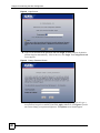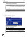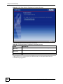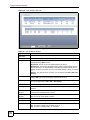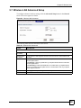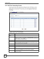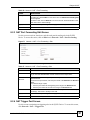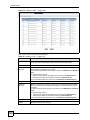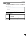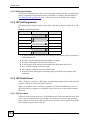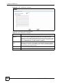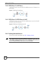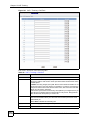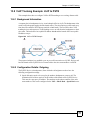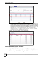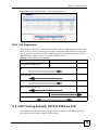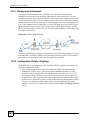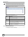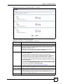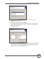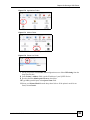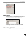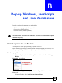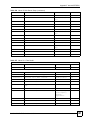
1
P-2302HWUDL-P1 Series
802.11g Wireless VoIP Station Gateway
with Built-in DECT Base Station
User’s Guide
Version 3.60
3/2007
Edition 2
www.zyxel.com
About This User's Guide
About This User's Guide
Intended Audience
This manual is intended for people who want to configure the ZyXEL Device using the web
configurator. You should have at least a basic knowledge of TCP/IP networking concepts and
topology.
Related Documentation
• Quick Start Guide
The Quick Start Guide is designed to help you get up and running right away. It contains
information on setting up your network and configuring for Internet access.
• Supporting Disk
Refer to the included CD for support documents.
• ZyXEL Web Site
Please refer to www.zyxel.com for additional support documentation and product
certifications.
User Guide Feedback
Help us help you. Send all User Guide-related comments, questions or suggestions for
improvement to the following address, or use e-mail instead. Thank you!
The Technical Writing Team,
ZyXEL Communications Corp.,
6 Innovation Road II,
Science-Based Industrial Park,
Hsinchu, 300, Taiwan.
E-mail: [email protected]
P-2302HWUDL-P1 Series User’s Guide
3
Document Conventions
Document Conventions
Warnings and Notes
These are how warnings and notes are shown in this User’s Guide.
1
"
Warnings tell you about things that could harm you or your device.
Notes tell you other important information (for example, other things you may
need to configure or helpful tips) or recommendations.
Syntax Conventions
• The P-2302HWUDL-P1 series may be referred to as the “ZyXEL Device”, the “device” or
the “system” in this User’s Guide.
• Product labels, screen names, field labels and field choices are all in bold font.
• A key stroke is denoted by square brackets and uppercase text, for example, [ENTER]
means the “enter” or “return” key on your keyboard.
• “Enter” means for you to type one or more characters and then press the [ENTER] key.
“Select” or “choose” means for you to use one of the predefined choices.
• A right angle bracket ( > ) within a screen name denotes a mouse click. For example,
Maintenance > Log > Log Setting means you first click Maintenance in the navigation
panel, then the Log sub menu and finally the Log Setting tab to get to that screen.
• Units of measurement may denote the “metric” value or the “scientific” value. For
example, “k” for kilo may denote “1000” or “1024”, “M” for mega may denote “1000000”
or “1048576” and so on.
• “e.g.,” is a shorthand for “for instance”, and “i.e.,” means “that is” or “in other words”.
4
P-2302HWUDL-P1 Series User’s Guide
Document Conventions
Icons Used in Figures
Figures in this User’s Guide may use the following generic icons. The ZyXEL Device icon is
not an exact representation of your device.
ZyXEL Device
Computer
Notebook computer
Server
DSLAM
Firewall
Telephone
Switch
Router
P-2302HWUDL-P1 Series User’s Guide
5
Safety Warnings
Safety Warnings
1
For your safety, be sure to read and follow all warning notices and instructions.
• Do NOT use this product near water, for example, in a wet basement or near a swimming
pool.
• Do NOT expose your device to dampness, dust or corrosive liquids.
• Do NOT store things on the device.
• Do NOT install, use, or service this device during a thunderstorm. There is a remote risk
of electric shock from lightning.
• Connect ONLY suitable accessories to the device.
• Do NOT open the device or unit. Opening or removing covers can expose you to
dangerous high voltage points or other risks. ONLY qualified service personnel should
service or disassemble this device. Please contact your vendor for further information.
• Make sure to connect the cables to the correct ports.
• Place connecting cables carefully so that no one will step on them or stumble over them.
• Always disconnect all cables from this device before servicing or disassembling.
• Use ONLY an appropriate power adaptor or cord for your device.
• Connect the power adaptor or cord to the right supply voltage (for example, 110V AC in
North America or 230V AC in Europe).
• Do NOT allow anything to rest on the power adaptor or cord and do NOT place the
product where anyone can walk on the power adaptor or cord.
• Do NOT use the device if the power adaptor or cord is damaged as it might cause
electrocution.
• If the power adaptor or cord is damaged, remove it from the power outlet.
• Do NOT attempt to repair the power adaptor or cord. Contact your local vendor to order a
new one.
• Do not use the device outside, and make sure all the connections are indoors. There is a
remote risk of electric shock from lightning.
• Do NOT obstruct the device ventilation slots, as insufficient airflow may harm your
device.
• Use only No. 26 AWG (American Wire Gauge) or larger telecommunication line cord.
• Antenna Warning! This device meets ETSI and FCC certification requirements when
using the included antenna(s). Only use the included antenna(s).
6
P-2302HWUDL-P1 Series User’s Guide
Safety Warnings
This product is recyclable. Dispose of it properly.
P-2302HWUDL-P1 Series User’s Guide
7
Safety Warnings
8
P-2302HWUDL-P1 Series User’s Guide
Contents Overview
Contents Overview
Introduction, Wizards and Status ......................................................................................... 31
Introducing the ZyXEL Device ................................................................................................... 33
Introducing the Web Configurator .............................................................................................. 39
Wizard Setup ............................................................................................................................. 47
Status Screens .......................................................................................................................... 71
Network ................................................................................................................................... 83
Wireless LAN ............................................................................................................................. 85
WAN ........................................................................................................................................ 101
LAN .......................................................................................................................................... 111
NAT ......................................................................................................................................... 123
VoIP ....................................................................................................................................... 131
SIP ........................................................................................................................................... 133
Phone ...................................................................................................................................... 147
Phone Book ............................................................................................................................. 163
PSTN Line ............................................................................................................................... 167
VoIP Trunking .......................................................................................................................... 169
Security ................................................................................................................................. 185
Firewall .................................................................................................................................... 187
Content Filter ........................................................................................................................... 195
Management ......................................................................................................................... 199
Static Route ............................................................................................................................. 201
Bandwidth MGMT .................................................................................................................... 205
Remote MGMT ........................................................................................................................ 217
UPnP ....................................................................................................................................... 225
Sharing a USB Printer ............................................................................................................. 237
File Sharing ............................................................................................................................. 251
Maintanence and Troubleshooting .................................................................................... 259
System ..................................................................................................................................... 261
Log ........................................................................................................................................... 269
Tools ........................................................................................................................................ 281
Troubleshooting ....................................................................................................................... 287
P-2302HWUDL-P1 Series User’s Guide
9
Contents Overview
Appendices and Index ......................................................................................................... 293
10
P-2302HWUDL-P1 Series User’s Guide
Table of Contents
Table of Contents
About This User's Guide .......................................................................................................... 3
Document Conventions............................................................................................................ 4
Safety Warnings........................................................................................................................ 6
Contents Overview ................................................................................................................... 9
Table of Contents.................................................................................................................... 11
List of Figures ......................................................................................................................... 21
List of Tables........................................................................................................................... 27
Part I: Introduction, Wizards and Status.............................................. 31
Chapter 1
Introducing the ZyXEL Device ............................................................................................... 33
1.1 Overview .............................................................................................................................. 33
1.1.1 VoIP Features ............................................................................................................ 33
1.1.2 VoIP Trunking Gateway ............................................................................................. 34
1.1.3 DECT Base Station Feature ....................................................................................... 34
1.1.4 ZyXEL Device’s USB Support .................................................................................... 35
1.1.5 ZyXEL Device’s Router Features .............................................................................. 35
1.2 Ways to Manage the ZyXEL Device .................................................................................... 36
1.3 Good Habits for Managing the ZyXEL Device ..................................................................... 36
1.4 LEDs (Lights) ....................................................................................................................... 36
Chapter 2
Introducing the Web Configurator ........................................................................................ 39
2.1 Web Configurator Overview ................................................................................................ 39
2.2 Accessing the Web Configurator ......................................................................................... 39
2.3 Resetting the ZyXEL Device ................................................................................................ 41
2.3.1 Reset Button and WLAN ............................................................................................ 42
2.4 Web Configurator Main Screen ........................................................................................... 42
2.4.1 Title Bar ...................................................................................................................... 43
2.4.2 Navigation Panel ........................................................................................................ 43
2.4.3 Main Window .............................................................................................................. 45
2.4.4 Status Bar .................................................................................................................. 45
P-2302HWUDL-P1 Series User’s Guide
11
Table of Contents
Chapter 3
Wizard Setup ........................................................................................................................... 47
3.1 Main Wizard Screen ............................................................................................................ 47
3.2 Connection Wizard .............................................................................................................. 48
3.2.1 Welcome .................................................................................................................... 49
3.2.2 System Information .................................................................................................... 49
3.2.3 Wireless Network Setup ............................................................................................. 50
3.2.4 ISP Parameters .......................................................................................................... 53
3.2.5 Your IP Address ......................................................................................................... 55
3.2.6 WAN IP Address Assignment .................................................................................... 56
3.2.7 MAC Address ............................................................................................................. 59
3.2.8 Apply the Connection Wizard Setting ......................................................................... 60
3.2.9 Finish .......................................................................................................................... 61
3.3 VoIP Setup Wizard .............................................................................................................. 61
3.3.1 SIP Settings ............................................................................................................... 62
3.3.2 Registration Complete ................................................................................................ 63
3.4 Bandwidth Management Wizard .......................................................................................... 65
3.4.1 Welcome .................................................................................................................... 66
3.4.2 General Information ................................................................................................... 67
3.4.3 Services Setup ........................................................................................................... 68
3.4.4 Priority Setup .............................................................................................................. 69
3.4.5 Finish .......................................................................................................................... 70
Chapter 4
Status Screens ........................................................................................................................ 71
4.1 Status Screen ...................................................................................................................... 71
4.2 Any IP Table Window .......................................................................................................... 74
4.3 DHCP Table Window ........................................................................................................... 75
4.4 VoIP Statistics Window ........................................................................................................ 75
4.5 BW MGMT Monitor Window ................................................................................................ 77
4.6 Packet Statistics Window .................................................................................................... 79
Part II: Network....................................................................................... 83
Chapter 5
Wireless LAN........................................................................................................................... 85
5.1 Wireless Network Overview ................................................................................................. 85
5.2 Wireless Security Overview ................................................................................................. 86
5.2.1 SSID ........................................................................................................................... 86
5.2.2 MAC Address Filter .................................................................................................... 86
5.2.3 User Authentication .................................................................................................... 86
12
P-2302HWUDL-P1 Series User’s Guide
Table of Contents
5.2.4 Encryption .................................................................................................................. 87
5.2.5 One-Touch Intelligent Security Technology (OTIST) ................................................. 88
5.3 Additional Wireless Terms ................................................................................................... 88
5.4 General WLAN Screen ........................................................................................................ 88
5.4.1 No Security ................................................................................................................. 89
5.4.2 WEP Encryption Screen ............................................................................................. 90
5.4.3 WPA(2)-PSK .............................................................................................................. 91
5.4.4 WPA(2) Authentication Screen .................................................................................. 93
5.5 OTIST Screen ...................................................................................................................... 94
5.5.1 Notes on OTIST ......................................................................................................... 96
5.6 MAC Filter
....................................................................................................................... 97
5.7 Wireless LAN Advanced Setup ........................................................................................... 99
Chapter 6
WAN ....................................................................................................................................... 101
6.1 WAN Overview .................................................................................................................. 101
6.1.1 PPPoE Encapsulation .............................................................................................. 101
6.1.2 WAN IP Address Assignment .................................................................................. 101
6.1.3 MAC Address ........................................................................................................... 102
6.1.4 RIP Setup ................................................................................................................. 102
6.1.5 DNS Server Address Assignment ............................................................................ 102
6.2 WAN Screens .................................................................................................................... 103
6.2.1 WAN Internet Connection Screen (Ethernet) ........................................................... 103
6.2.2 WAN Internet Connection Screen (Roadrunner) ...................................................... 104
6.2.3 WAN Internet Connection Screen (PPPoE) ............................................................. 105
6.2.4 WAN Advanced Screen ........................................................................................... 107
6.2.5 WAN Traffic Redirect Screen ................................................................................... 109
Chapter 7
LAN......................................................................................................................................... 111
7.1 LAN Overview .................................................................................................................... 111
7.1.1 IP Address and Subnet Mask ................................................................................... 111
7.1.2 DHCP Setup ............................................................................................................. 112
7.1.3 LAN TCP/IP .............................................................................................................. 112
7.1.4 DNS Server Address ................................................................................................ 112
7.1.5 RIP Setup ................................................................................................................. 113
7.1.6 Multicast ................................................................................................................... 113
7.1.7 Any IP ....................................................................................................................... 114
7.2 LAN Screens ..................................................................................................................... 115
7.2.1 LAN IP Screen ......................................................................................................... 115
7.2.2 LAN DHCP Setup Screen ........................................................................................ 116
7.2.3 LAN Static DHCP Screen ......................................................................................... 117
7.2.4 LAN Client List Screen ............................................................................................. 118
P-2302HWUDL-P1 Series User’s Guide
13
Table of Contents
7.2.5 LAN IP Alias Screen ................................................................................................. 119
7.2.6 LAN Advanced Screen ............................................................................................. 120
Chapter 8
NAT......................................................................................................................................... 123
8.1 NAT Overview ................................................................................................................... 123
8.1.1 Port Forwarding: Services and Port Numbers .......................................................... 123
8.1.2 Trigger Port Forwarding ........................................................................................... 124
8.1.3 SIP ALG ................................................................................................................... 125
8.2 NAT Screens ..................................................................................................................... 125
8.2.1 NAT General Screen ................................................................................................ 125
8.2.2 NAT Port Forwarding Screen ................................................................................... 126
8.2.3 NAT Port Forwarding Edit Screen ............................................................................ 127
8.2.4 NAT Trigger Port Screen .......................................................................................... 127
8.2.5 NAT ALG Screen ..................................................................................................... 129
Part III: VoIP.......................................................................................... 131
Chapter 9
SIP .......................................................................................................................................... 133
9.1 SIP Overview ..................................................................................................................... 133
9.1.1 Introduction to VoIP .................................................................................................. 133
9.1.2 Introduction to SIP .................................................................................................... 133
9.1.3 SIP Identities ............................................................................................................ 133
9.1.4 SIP Call Progression ................................................................................................ 134
9.1.5 SIP Client Server ...................................................................................................... 134
9.1.6 RTP .......................................................................................................................... 136
9.1.7 NAT and SIP ............................................................................................................ 136
9.1.8 Voice Coding ............................................................................................................ 137
9.1.9 PSTN Call Setup Signaling ...................................................................................... 138
9.1.10 MWI (Message Waiting Indication) ........................................................................ 138
9.2 Custom Tones (IVR) .......................................................................................................... 138
9.2.1 Quality of Service (QoS) .......................................................................................... 139
9.3 SIP Screens ....................................................................................................................... 140
9.3.1 SIP Settings Screen ................................................................................................. 140
9.3.2 Advanced SIP Setup Screen .................................................................................... 141
9.3.3 SIP QoS Screen ....................................................................................................... 145
Chapter 10
Phone ..................................................................................................................................... 147
10.1 Analog Phone Overview .................................................................................................. 147
14
P-2302HWUDL-P1 Series User’s Guide
Table of Contents
10.1.1 Voice Activity Detection/Silence Suppression/Comfort Noise ................................ 147
10.1.2 Echo Cancellation .................................................................................................. 147
10.1.3 Supplementary Phone Services Overview ............................................................. 147
10.2 Phone Screens ................................................................................................................ 150
10.2.1 Analog Phone Screen ............................................................................................ 150
10.2.2 Advanced Analog Phone Setup Screen ................................................................. 151
10.3 DECT Base Station Overview ......................................................................................... 153
10.3.1 DECT Phone Registration ...................................................................................... 153
10.3.2 Using your DECT Phone ........................................................................................ 155
10.3.3 DECT Phone Screen .............................................................................................. 156
10.3.4 Common Phone Settings Screen ........................................................................... 158
10.3.5 Phone Region Screen ............................................................................................ 158
10.3.6 Phone Ext. Table Setup Screen ............................................................................. 159
10.3.7 Advanced Phone Ext. Table Setup Screen ............................................................ 161
Chapter 11
Phone Book ........................................................................................................................... 163
11.1 Phone Book Screens ....................................................................................................... 163
11.1.1 Incoming Call Policy Screen .................................................................................. 163
11.1.2 Speed Dial Screen ................................................................................................. 165
Chapter 12
PSTN Line .............................................................................................................................. 167
12.1 PSTN Line Overview ....................................................................................................... 167
12.2 PSTN Line Screen ........................................................................................................... 167
Chapter 13
VoIP Trunking........................................................................................................................ 169
13.1 VoIP Trunking Overview ................................................................................................. 169
13.2 VoIP Trunking and Security ............................................................................................. 169
13.2.1 Auto Attendant and Authentication ......................................................................... 170
13.2.2 Peer Call Authentication ......................................................................................... 170
13.3 Call Rules ........................................................................................................................ 171
13.4 VoIP Trunking Scenarios ................................................................................................. 171
13.4.1 VoIP Phone To PSTN Phone ................................................................................. 171
13.4.2 PSTN Phone To VoIP Phone ................................................................................. 172
13.4.3 PSTN Phone To PSTN Phone via VoIP ................................................................. 172
13.5 Trunking General Screen ................................................................................................ 172
13.6 Trunking Peer Call Screen .............................................................................................. 173
13.7 Trunking Call Rule Screen ............................................................................................... 175
13.8 VoIP Trunking Example: VoIP to PSTN .......................................................................... 177
13.8.1 Background Information ......................................................................................... 177
13.8.2 Configuration Details: Outgoing ............................................................................. 177
P-2302HWUDL-P1 Series User’s Guide
15
Table of Contents
13.8.3 Configuration Details: Incoming ............................................................................. 178
13.8.4 Call Progression ..................................................................................................... 179
13.9 VoIP Trunking Example: PSTN to PSTN via VoIP .......................................................... 179
13.9.1 Background Information ......................................................................................... 180
13.9.2 Configuration Details: Outgoing ............................................................................. 180
13.9.3 Configuration Details: Incoming ............................................................................. 182
13.9.4 Call Progression ..................................................................................................... 183
Part IV: Security ................................................................................... 185
Chapter 14
Firewall................................................................................................................................... 187
14.1 Firewall Overview ............................................................................................................ 187
14.1.1 Stateful Inspection Firewall .................................................................................... 187
14.1.2 About the ZyXEL Device Firewall ........................................................................... 187
14.1.3 Guidelines For Enhancing Security With Your Firewall .......................................... 188
14.1.4 The Firewall, NAT and Remote Management ........................................................ 188
14.2 Triangle Route ................................................................................................................. 189
14.2.1 The “Triangle Route” Problem ................................................................................ 189
14.2.2 Solving the “Triangle Route” Problem .................................................................... 190
14.3 Firewall Screens .............................................................................................................. 191
14.3.1 General Firewall Screen ......................................................................................... 191
14.3.2 Firewall Services Screen ........................................................................................ 192
Chapter 15
Content Filter......................................................................................................................... 195
15.1 Content Filtering Overview .............................................................................................. 195
15.2 Content Filtering Screens ................................................................................................ 195
15.2.1 Content Filter Screen ............................................................................................. 195
15.2.2 Content Filter Schedule Screen ............................................................................. 197
Part V: Management ............................................................................ 199
Chapter 16
Static Route ........................................................................................................................... 201
16.1 Static Route Overview ..................................................................................................... 201
16.2 Static Route Screens ....................................................................................................... 201
16.2.1 IP Static Route Screen ........................................................................................... 201
16.2.2 IP Static Route Edit Screen .................................................................................... 202
16
P-2302HWUDL-P1 Series User’s Guide
Table of Contents
Chapter 17
Bandwidth MGMT.................................................................................................................. 205
17.1 Bandwidth Management Overview .................................................................................. 205
17.1.1 Bandwidth Classes and Filters ............................................................................... 205
17.1.2 Proportional Bandwidth Allocation ......................................................................... 206
17.1.3 Application-based Bandwidth Management ........................................................... 206
17.1.4 Subnet-based Bandwidth Management ................................................................. 206
17.1.5 Application- and Subnet-based Bandwidth Management ...................................... 206
17.1.6 Scheduler ............................................................................................................... 206
17.1.7 Maximize Bandwidth Usage ................................................................................... 207
17.1.8 Bandwidth Borrowing ............................................................................................. 209
17.1.9 Over Allotment of Bandwidth .................................................................................. 210
17.2 Bandwidth Management Screens .................................................................................... 210
17.2.1 Bandwidth Management Summary Screen ............................................................ 210
17.2.2 Bandwidth Class Setup Screen .............................................................................. 213
17.2.3 Bandwidth Class Edit Screen ................................................................................. 214
17.2.4 Bandwidth Monitor Screen ..................................................................................... 215
Chapter 18
Remote MGMT....................................................................................................................... 217
18.1 Remote Management Overview ...................................................................................... 217
18.1.1 Remote Management Limitations .......................................................................... 217
18.1.2 Remote Management and NAT ............................................................................. 217
18.1.3 System Timeout ..................................................................................................... 218
18.2 Remote Management Screens ........................................................................................ 218
18.2.1 WWW Screen ......................................................................................................... 218
18.2.2 Telnet Screen ......................................................................................................... 218
18.2.3 FTP Screen ............................................................................................................ 219
18.3 SNMP ............................................................................................................................. 220
18.3.1 Supported MIBs ..................................................................................................... 221
18.3.2 SNMP Traps ........................................................................................................... 221
18.3.3 Configuring SNMP ................................................................................................. 221
18.3.4 DNS Screen ........................................................................................................... 222
18.3.5 Security Screen ...................................................................................................... 223
Chapter 19
UPnP ...................................................................................................................................... 225
19.1 Introducing Universal Plug and Play ................................................................................ 225
19.1.1 How do I know if I'm using UPnP? ......................................................................... 225
19.1.2 NAT Traversal ........................................................................................................ 225
19.1.3 Cautions with UPnP ............................................................................................... 225
19.1.4 UPnP and ZyXEL ................................................................................................... 226
19.2 UPnP Examples .............................................................................................................. 226
P-2302HWUDL-P1 Series User’s Guide
17
Table of Contents
19.2.1 Installing UPnP in Windows Example .................................................................... 226
19.2.2 Using UPnP in Windows XP Example ................................................................... 229
19.3 General ............................................................................................................................ 235
Chapter 20
Sharing a USB Printer ..........................................................................................................237
20.1 Overview .......................................................................................................................... 237
20.2 Requirements .................................................................................................................. 237
20.3 Configure a TCP/IP Printer Port ...................................................................................... 238
20.4 Print Server Screen ......................................................................................................... 242
20.5 Adding a New Printer Example ........................................................................................ 243
20.6 Macintosh OS X Adding Printer Example ........................................................................ 248
Chapter 21
File Sharing ........................................................................................................................... 251
21.1 File Sharing Implementation Overview ............................................................................ 251
21.2 Sharing Files via the ZyXEL Device ................................................................................ 252
21.2.1 Using the Workgroup Name to Share Files ............................................................ 252
21.3 User Accounts ................................................................................................................. 253
21.4 File Sharing - General Screen ......................................................................................... 253
21.5 Examples of Accessing Files via the ZyXEL Device ....................................................... 255
21.5.1 Using Windows Explorer to Share Files ................................................................. 255
21.5.2 Using the Run Utility to Share Files ....................................................................... 256
21.5.3 Using FTP to Share Files ....................................................................................... 256
21.5.4 Using the Workgroup Name to Access Files .......................................................... 257
Part VI: Maintanence and Troubleshooting....................................... 259
Chapter 22
System ................................................................................................................................... 261
22.1 System Overview ............................................................................................................. 261
22.1.1 System Name ......................................................................................................... 261
22.1.2 Domain Name ........................................................................................................ 261
22.1.3 General System Screen ......................................................................................... 261
22.2 Dynamic DNS Overview .................................................................................................. 262
22.2.1 DNS Server Address Assignment .......................................................................... 263
22.2.2 Dynamic DNS ......................................................................................................... 263
22.2.3 Dynamic DNS Screen ............................................................................................ 263
22.3 Time Setting Overview .................................................................................................... 265
22.3.1 Pre-defined NTP Time Servers List ....................................................................... 265
22.3.2 Resetting the Time ................................................................................................. 266
18
P-2302HWUDL-P1 Series User’s Guide
Table of Contents
22.3.3 Time Settings Screen ............................................................................................. 266
Chapter 23
Log ......................................................................................................................................... 269
23.1 Logs Overview ................................................................................................................. 269
23.1.1 Alerts ...................................................................................................................... 269
23.1.2 Syslog Logs ............................................................................................................ 269
23.2 Logs Screens ................................................................................................................... 270
23.2.1 View Log Screen .................................................................................................... 270
23.2.2 Log Settings Screen ............................................................................................... 271
23.3 Log Message Descriptions .............................................................................................. 273
Chapter 24
Tools ...................................................................................................................................... 281
24.1 Tools Overview ................................................................................................................ 281
24.1.1 ZyXEL Firmware .................................................................................................... 281
24.2 Tools Screens .................................................................................................................. 281
24.2.1 Firmware Screen .................................................................................................... 281
24.2.2 Firmware Upload Screens ...................................................................................... 282
24.2.3 Configuration Screen ............................................................................................. 283
24.2.4 Restore Configuration Screens .............................................................................. 284
24.2.5 Restart Screen ....................................................................................................... 285
Chapter 25
Troubleshooting.................................................................................................................... 287
25.1 Power, Hardware Connections, and LEDs ...................................................................... 287
25.2 ZyXEL Device Access and Login .................................................................................... 288
25.3 Internet Access ................................................................................................................ 289
25.4 Phone Calls and VoIP ..................................................................................................... 290
25.5 Problems With USB Device Connection .......................................................................... 290
Part VII: Appendices and Index .......................................................... 293
Appendix A Product Specifications ...................................................................................... 295
Appendix B Pop-up Windows, JavaScripts and Java Permissions ...................................... 301
Appendix C IP Addresses and Subnetting ........................................................................... 307
Appendix D Setting up Your Computer’s IP Address ........................................................... 315
Appendix E SIP Passthrough ............................................................................................... 329
Appendix F Internal SPTGEN .............................................................................................. 331
P-2302HWUDL-P1 Series User’s Guide
19
Table of Contents
Appendix G Services............................................................................................................ 347
Appendix H Legal Information .............................................................................................. 351
Appendix I Customer Support .............................................................................................. 355
Index....................................................................................................................................... 359
20
P-2302HWUDL-P1 Series User’s Guide
List of Figures
List of Figures
Figure 1 ZyXEL Device’s VoIP Features ................................................................................................ 33
Figure 2 ZyXEL Device as a VoIP Trunking Gateway ............................................................................ 34
Figure 3 DECT Base Station Feature ..................................................................................................... 34
Figure 4 File Sharing Overview .............................................................................................................. 35
Figure 5 ZyXEL Device’s Router Features ............................................................................................. 35
Figure 6 LEDs on the Side Panel ........................................................................................................... 37
Figure 7 LED on the Top of the Device .................................................................................................. 37
Figure 8 Login Screen ............................................................................................................................ 40
Figure 9 Change Password Screen ........................................................................................................ 40
Figure 10 Select Mode Screen ............................................................................................................... 41
Figure 11 Main Screen ........................................................................................................................... 42
Figure 12 Main Wizard Screen ............................................................................................................... 47
Figure 13 Connection Wizard > Welcome .............................................................................................. 49
Figure 14 Connection Wizard > System Information .............................................................................. 49
Figure 15 Wireless LAN .......................................................................................................................... 50
Figure 16 Manually Assign a WPA/WPA2 key ....................................................................................... 51
Figure 17 Manually Assign a WEP key .................................................................................................. 52
Figure 18 Manually Assign a WEP key .................................................................................................. 53
Figure 19 Connection Wizard > ISP Parameters (Ethernet) ................................................................... 54
Figure 20 Connection Wizard > ISP Parameters (PPPoE) ..................................................................... 55
Figure 21 Connection Wizard > IP Address ........................................................................................... 55
Figure 22 Connection Wizard > IP Address (Ethernet) .......................................................................... 56
Figure 23 Connection Wizard > IP Address (PPPoE) ............................................................................ 58
Figure 24 Connection Wizard > MAC Address ....................................................................................... 59
Figure 25 Connection Wizard > Apply .................................................................................................... 60
Figure 26 Connection Wizard > Finish ................................................................................................... 61
Figure 27 VoIP Setup Wizard > SIP Settings ......................................................................................... 62
Figure 28 VoIP Setup Wizard > Registration Test .................................................................................. 63
Figure 29 VoIP Setup Wizard > Registration Complete (Success) ........................................................ 64
Figure 30 VoIP Setup Wizard > Registration Complete (Fail) ................................................................ 65
Figure 31 Bandwidth Management Wizard > Welcome ......................................................................... 66
Figure 32 Bandwidth Management Wizard > General Information ......................................................... 67
Figure 33 Bandwidth Management Wizard > Services Setup ................................................................ 68
Figure 34 Bandwidth Management Wizard > Priority Setup ................................................................... 69
Figure 35 Bandwidth Management Wizard > Finish ............................................................................... 70
Figure 36 Status Screen ......................................................................................................................... 71
Figure 37 Any IP Table Window ............................................................................................................. 74
Figure 38 DHCP Table Window ............................................................................................................. 75
P-2302HWUDL-P1 Series User’s Guide
21
List of Figures
Figure 39 VoIP Statistics Window .......................................................................................................... 76
Figure 40 BW MGMT Monitor Window ................................................................................................... 78
Figure 41 Packet Statistics Window ....................................................................................................... 80
Figure 42 Example of a Wireless Network ............................................................................................. 85
Figure 43 Wireless LAN: General .......................................................................................................... 89
Figure 44 Wireless: No Security ............................................................................................................. 90
Figure 45 Wireless: Static WEP Encryption ........................................................................................... 91
Figure 46 Wireless: WPA(2)-PSK ........................................................................................................... 92
Figure 47 Wireless: WPA(2) ................................................................................................................... 93
Figure 48 Network > Wireless LAN > OTIST .......................................................................................... 94
Figure 49 Example: Wireless Client OTIST Screen ............................................................................... 95
Figure 50 OTIST: Settings ...................................................................................................................... 96
Figure 51 OTIST: In Progress on the Wireless Device ........................................................................... 96
Figure 52 Start OTIST? .......................................................................................................................... 97
Figure 53 MAC Address Filter ................................................................................................................ 98
Figure 54 Wireless LAN: Advanced ........................................................................................................ 99
Figure 55 Network > WAN > Internet Connection (Ethernet) ............................................................... 103
Figure 56 Network > WAN > Internet Connection (Roadrunner) .......................................................... 105
Figure 57 Network > WAN > Internet Connection (PPPoE) ................................................................. 106
Figure 58 Network > WAN > Advanced ................................................................................................ 108
Figure 59 Network > WAN > Traffic Redirect ....................................................................................... 109
Figure 60 Any IP Example .................................................................................................................... 114
Figure 61 Network > LAN > IP .............................................................................................................. 115
Figure 62 Network > LAN > DHCP Setup ............................................................................................ 116
Figure 63 Network > LAN > Static DHCP ............................................................................................. 117
Figure 64 Network > LAN > Client List ................................................................................................. 118
Figure 65 Network > LAN > IP Alias ..................................................................................................... 119
Figure 66 Network > LAN > Advanced ................................................................................................. 120
Figure 67 Multiple Servers Behind NAT Example ................................................................................ 123
Figure 68 Trigger Port Forwarding Process: Example ......................................................................... 124
Figure 69 Network > NAT > General .................................................................................................... 125
Figure 70 Network > NAT > Port Forwarding ....................................................................................... 126
Figure 71 Network > NAT > Port Forwarding > Edit ............................................................................. 127
Figure 72 Network > NAT > Trigger Port .............................................................................................. 128
Figure 73 Network > NAT > ALG .......................................................................................................... 129
Figure 74 SIP User Agent ..................................................................................................................... 135
Figure 75 SIP Proxy Server .................................................................................................................. 135
Figure 76 SIP Redirect Server .............................................................................................................. 136
Figure 77 STUN .................................................................................................................................... 137
Figure 78 DiffServ: Differentiated Service Field ................................................................................... 139
Figure 79 VoIP > SIP > SIP Settings .................................................................................................... 140
Figure 80 VoIP > SIP > SIP Settings > Advanced ................................................................................ 142
Figure 81 VoIP > SIP > QoS ................................................................................................................ 145
22
P-2302HWUDL-P1 Series User’s Guide
List of Figures
Figure 82 VoIP > Phone > Analog Phone ............................................................................................ 151
Figure 83 VoIP > Phone > Analog Phone > Advanced ........................................................................ 152
Figure 84 DECT Base Station Overview .............................................................................................. 153
Figure 85 DECT Base Station Button - Top of the ZyXEL Device ........................................................ 154
Figure 86 DECT Base Station - Phone Registration ........................................................................... 154
Figure 87 Using Your DECT Phone ..................................................................................................... 155
Figure 88 VoIP > Phone > DECT Phone .............................................................................................. 157
Figure 89 VoIP > Phone > Common .................................................................................................... 158
Figure 90 VoIP > Phone > Region ........................................................................................................ 158
Figure 91 VoIP > Phone > Ext. Table ................................................................................................... 160
Figure 92 VoIP > Phone > Ext. Table > Advanced ............................................................................... 161
Figure 93 VoIP > Phone Book > Incoming Call Policy ......................................................................... 163
Figure 94 VoIP > PSTN Line > General ............................................................................................... 168
Figure 95 Peer Devices Connecting ..................................................................................................... 170
Figure 96 VoIP Phone To PSTN Phone ............................................................................................... 171
Figure 97 PSTN Phone To VoIP Phone ............................................................................................... 172
Figure 98 PSTN Phone To PSTN Phone via VoIP ............................................................................... 172
Figure 99 VoIP > Trunking > General ................................................................................................... 173
Figure 100 VoIP > Trunking > Peer Call .............................................................................................. 174
Figure 101 VoIP > Trunking > Call Rule ............................................................................................... 176
Figure 102 VoIP to PSTN Example ...................................................................................................... 177
Figure 103 VoIP to PSTN Example - Speed Dial Screen ..................................................................... 178
Figure 104 VoIP to PSTN Example - Outgoing Authentication ............................................................ 178
Figure 105 VoIP to PSTN Example - Incoming Authentication ............................................................ 179
Figure 106 PSTN to PSTN Example .................................................................................................... 180
Figure 107 PSTN to PSTN Example: General Configuration ............................................................... 181
Figure 108 PSTN to PSTN Example - Outgoing Authentication ........................................................... 181
Figure 109 PSTN to PSTN Example - Call Rule .................................................................................. 182
Figure 110 PSTN to PSTN Example - Incoming Authentication ........................................................... 182
Figure 111 Firewall Rule Directions ...................................................................................................... 188
Figure 112 Ideal Firewall Setup ............................................................................................................ 189
Figure 113 “Triangle Route” Problem ................................................................................................... 190
Figure 114 IP Alias ............................................................................................................................... 191
Figure 115 Security > Firewall > General ............................................................................................. 191
Figure 116 Security > Firewall > Services ............................................................................................ 192
Figure 117 Security > Content Filter > Filter ......................................................................................... 196
Figure 118 Security > Content Filter > Schedule .................................................................................. 197
Figure 119 Example of Static Routing Topology .................................................................................. 201
Figure 120 Management > Static Route > IP Static Route ................................................................... 202
Figure 121 Management > Static Route > IP Static Route > Edit ........................................................ 203
Figure 122 Subnet-based Bandwidth Management Example .............................................................. 206
Figure 123 Management > Bandwidth MGMT > Summary .................................................................. 211
Figure 124 Management > Bandwidth MGMT > Class Setup .............................................................. 213
P-2302HWUDL-P1 Series User’s Guide
23
List of Figures
Figure 125 Management > Bandwidth MGMT > Class Setup > Edit .................................................... 214
Figure 126 Management > Bandwidth MGMT > Monitor ..................................................................... 216
Figure 127 Management > Remote MGMT > WWW ........................................................................... 218
Figure 128 Management > Remote MGMT > Telnet ............................................................................ 219
Figure 129 Management > Remote MGMT > FTP ............................................................................... 219
Figure 130 SNMP Management Model ................................................................................................ 220
Figure 131 Management > Remote MGMT > SNMP ........................................................................... 222
Figure 132 Management > Remote MGMT > DNS .............................................................................. 223
Figure 133 Management > Remote MGMT > Security ......................................................................... 223
Figure 134 Add/Remove Programs: Windows Setup: Communication ................................................ 226
Figure 135 Add/Remove Programs: Windows Setup: Communication: Components .......................... 227
Figure 136 Network Connections ......................................................................................................... 227
Figure 137 Windows Optional Networking Components Wizard .......................................................... 228
Figure 138 Networking Services ........................................................................................................... 228
Figure 139 Network Connections ......................................................................................................... 229
Figure 140 Internet Connection Properties .......................................................................................... 230
Figure 141 Internet Connection Properties: Advanced Settings ........................................................... 231
Figure 142 Internet Connection Properties: Advanced Settings: Add .................................................. 231
Figure 143 System Tray Icon ............................................................................................................... 232
Figure 144 Internet Connection Status ................................................................................................. 232
Figure 145 Network Connections ......................................................................................................... 233
Figure 146 Network Connections: My Network Places ........................................................................ 234
Figure 147 Network Connections: My Network Places: Properties: Example ...................................... 234
Figure 148 Management > UPnP ......................................................................................................... 235
Figure 149 Sharing a USB Printer ........................................................................................................ 237
Figure 150 Open Printers Window ....................................................................................................... 238
Figure 151 Open Printer Properties ...................................................................................................... 239
Figure 152 Printer Properties Window .................................................................................................. 239
Figure 153 Add a Port Window ............................................................................................................. 239
Figure 154 Add a Port Wizard .............................................................................................................. 240
Figure 155 Enter IP Address of the ZyXEL Device .............................................................................. 240
Figure 156 Custom Port Settings ......................................................................................................... 241
Figure 157 Custom Port Settings ......................................................................................................... 241
Figure 158 Finish Adding the TCP/IP Port ........................................................................................... 242
Figure 159 Configuring Print Server ..................................................................................................... 242
Figure 160 Printers Folder .................................................................................................................... 243
Figure 161 Add Printer Wizard: Welcome ............................................................................................ 244
Figure 162 Add Printer Wizard: Local or Network Printer ..................................................................... 244
Figure 163 Add Printer Wizard: Select the Printer Port ....................................................................... 245
Figure 164 Add Printer Wizard: Printer Driver ..................................................................................... 245
Figure 165 Add Printer Wizard: Use Existing Driver ............................................................................. 246
Figure 166 Add Printer Wizard: Name Your Printer ............................................................................ 246
Figure 167 Add Printer Wizard: Printer Sharing .................................................................................. 247
24
P-2302HWUDL-P1 Series User’s Guide
List of Figures
Figure 168 Add Printer Wizard: Print Test Page ................................................................................. 247
Figure 169 Add Printer Wizard Complete ............................................................................................. 248
Figure 170 Macintosh HD ..................................................................................................................... 248
Figure 171 Macintosh HD folder ........................................................................................................... 248
Figure 172 Applications Folder ............................................................................................................. 249
Figure 173 Utilities Folder ..................................................................................................................... 249
Figure 174 Printer List Folder ............................................................................................................... 249
Figure 175 Printer Configuration .......................................................................................................... 250
Figure 176 Printer Model ...................................................................................................................... 250
Figure 177 Print Server ........................................................................................................................ 250
Figure 178 File Sharing Overview ........................................................................................................ 251
Figure 179 Check the Workgroup Name .............................................................................................. 253
Figure 180 File Sharing Login .............................................................................................................. 253
Figure 181 Management > File Sharing ............................................................................................... 254
Figure 182 File Sharing via Windows Explorer ..................................................................................... 256
Figure 183 Run Utility to Browse Files ................................................................................................. 256
Figure 184 File Sharing via FTP: Address ........................................................................................... 257
Figure 185 File Sharing via FTP: Login ............................................................................................... 257
Figure 186 File Sharing via FTP: Login ............................................................................................... 257
Figure 187 Browse to a File Share via Workgroup Name .................................................................... 258
Figure 188 Maintenance > System > General ...................................................................................... 262
Figure 189 Maintenance > System > Dynamic DNS ............................................................................ 264
Figure 190 Maintenance > System > Time Setting .............................................................................. 266
Figure 191 Maintenance > Logs > View Log ........................................................................................ 270
Figure 192 Maintenance > Logs > Log Settings ................................................................................... 271
Figure 193 Maintenance > Tools > Firmware ....................................................................................... 281
Figure 194 Firmware Upload In Process .............................................................................................. 282
Figure 195 Network Temporarily Disconnected ................................................................................... 282
Figure 196 Firmware Upload Error ....................................................................................................... 283
Figure 197 Maintenance > Tools > Configuration ................................................................................ 283
Figure 198 Configuration Upload Successful ....................................................................................... 284
Figure 199 Network Temporarily Disconnected ................................................................................... 284
Figure 200 Configuration Upload Error ................................................................................................. 285
Figure 201 Maintenance > Tools > Restart .......................................................................................... 285
Figure 202 Maintenance > Tools > Restart > In Progress .................................................................... 285
Figure 203 Pop-up Blocker ................................................................................................................... 301
Figure 204 Internet Options: Privacy .................................................................................................... 302
Figure 205 Internet Options: Privacy .................................................................................................... 303
Figure 206 Pop-up Blocker Settings ..................................................................................................... 303
Figure 207 Internet Options: Security ................................................................................................... 304
Figure 208 Security Settings - Java Scripting ....................................................................................... 305
Figure 209 Security Settings - Java ...................................................................................................... 305
Figure 210 Java (Sun) .......................................................................................................................... 306
P-2302HWUDL-P1 Series User’s Guide
25
List of Figures
Figure 211 Network Number and Host ID ............................................................................................ 308
Figure 212 Subnetting Example: Before Subnetting ............................................................................ 310
Figure 213 Subnetting Example: After Subnetting ............................................................................... 311
Figure 214 WIndows 95/98/Me: Network: Configuration ...................................................................... 316
Figure 215 Windows 95/98/Me: TCP/IP Properties: IP Address .......................................................... 317
Figure 216 Windows 95/98/Me: TCP/IP Properties: DNS Configuration .............................................. 318
Figure 217 Windows XP: Start Menu ................................................................................................... 319
Figure 218 Windows XP: Control Panel ............................................................................................... 319
Figure 219 Windows XP: Control Panel: Network Connections: Properties ......................................... 320
Figure 220 Windows XP: Local Area Connection Properties ............................................................... 320
Figure 221 Windows XP: Internet Protocol (TCP/IP) Properties .......................................................... 321
Figure 222 Windows XP: Advanced TCP/IP Properties ....................................................................... 322
Figure 223 Windows XP: Internet Protocol (TCP/IP) Properties .......................................................... 323
Figure 224 Macintosh OS X: Apple Menu ............................................................................................ 323
Figure 225 Macintosh OS X: Network .................................................................................................. 324
Figure 226 Red Hat 9.0: KDE: Network Configuration: Devices ......................................................... 325
Figure 227 Red Hat 9.0: KDE: Ethernet Device: General ................................................................... 326
Figure 228 Red Hat 9.0: KDE: Network Configuration: DNS ............................................................... 326
Figure 229 Red Hat 9.0: KDE: Network Configuration: Activate ......................................................... 327
Figure 230 Red Hat 9.0: Dynamic IP Address Setting in ifconfig-eth0 ................................................ 327
Figure 231 Red Hat 9.0: Static IP Address Setting in ifconfig-eth0
Figure 232 Red Hat 9.0: DNS Settings in resolv.conf
................................................... 327
....................................................................... 328
Figure 233 Red Hat 9.0: Restart Ethernet Card .................................................................................. 328
Figure 234 Red Hat 9.0: Checking TCP/IP Properties ........................................................................ 328
Figure 235 Configuration Text File Format: Column Descriptions ........................................................ 331
Figure 236 Invalid Parameter Entered: Command Line Example ........................................................ 332
Figure 237 Valid Parameter Entered: Command Line Example ........................................................... 332
Figure 238 Internal SPTGEN FTP Download Example ........................................................................ 333
Figure 239 Internal SPTGEN FTP Upload Example ............................................................................ 333
26
P-2302HWUDL-P1 Series User’s Guide
List of Tables
List of Tables
Table 1 LED Descriptions ...................................................................................................................... 37
Table 2 Web Configurator Icons in the Title Bar .................................................................................... 43
Table 3 Navigation Panel Summary ...................................................................................................... 43
Table 4 Main Wizard Screen ................................................................................................................. 48
Table 5 Connection Wizard > Welcome ................................................................................................ 49
Table 6 Connection Wizard > System Information ................................................................................ 50
Table 7 Wireless LAN Setup Wizard 2 .................................................................................................. 50
Table 8 Manually Assign a WPA or WPA2 key ..................................................................................... 51
Table 9 Manually Assign a WEP key ..................................................................................................... 52
Table 10 Manually Assign a WEP key ................................................................................................... 53
Table 11 Connection Wizard > ISP Parameters (Ethernet) ................................................................... 54
Table 12 Connection Wizard > ISP Parameters (PPPoE) ..................................................................... 55
Table 13 Connection Wizard > IP Address ............................................................................................ 56
Table 14 Connection Wizard > IP Address (Ethernet) ........................................................................... 57
Table 15 Connection Wizard > IP Address (PPPoE) ............................................................................. 58
Table 16 Connection Wizard > MAC Address ....................................................................................... 59
Table 17 Connection Wizard > Apply .................................................................................................... 60
Table 18 Connection Wizard > Finish .................................................................................................... 61
Table 19 VoIP Setup Wizard > SIP Settings ......................................................................................... 62
Table 20 VoIP Setup Wizard > Registration Complete (Success) ......................................................... 64
Table 21 VoIP Setup Wizard > Registration Complete (Fail) ................................................................ 65
Table 22 Bandwidth Management Wizard > Welcome .......................................................................... 66
Table 23 Bandwidth Management Wizard > General Information ......................................................... 67
Table 24 Bandwidth Management Wizard > Services Setup ................................................................ 68
Table 25 Bandwidth Management Wizard > Priority Setup ................................................................... 69
Table 26 Bandwidth Management Wizard > Finish ............................................................................... 70
Table 27 Status Screen ......................................................................................................................... 72
Table 28 Any IP Table Window ............................................................................................................. 74
Table 29 DHCP Table Window .............................................................................................................. 75
Table 30 VoIP Statistics Window ........................................................................................................... 76
Table 31 BW MGMT Monitor Window ................................................................................................... 78
Table 32 Packet Statistics Window ....................................................................................................... 80
Table 33 Types of Encryption for Each Type of Authentication ............................................................. 87
Table 34 Additional Wireless Terms ...................................................................................................... 88
Table 35 Wireless LAN: General ........................................................................................................... 89
Table 36 Wireless No Security .............................................................................................................. 90
Table 37 Wireless: Static WEP Encryption ............................................................................................ 91
Table 38 Wireless: WPA(2)-PSK ........................................................................................................... 92
P-2302HWUDL-P1 Series User’s Guide
27
List of Tables
Table 39 Wireless: WPA(2) ................................................................................................................... 93
Table 40 Network > Wireless LAN > OTIST .......................................................................................... 95
Table 41 MAC Address Filter ................................................................................................................ 98
Table 42 Wireless LAN: Advanced ........................................................................................................ 99
Table 43 Private IP Address Ranges .................................................................................................. 101
Table 44 Network > WAN > Internet Connection (Ethernet) ............................................................... 104
Table 45 Network > WAN > Internet Connection (Roadrunner) .......................................................... 105
Table 46 Network > WAN > Internet Connection (PPPoE) ................................................................. 106
Table 47 Network > WAN > Advanced ................................................................................................ 108
Table 48 Network > WAN > Traffic Redirect ....................................................................................... 110
Table 49 Network > LAN > IP .............................................................................................................. 116
Table 50 Network > LAN > DHCP Setup ............................................................................................. 116
Table 51 Network > LAN > Static DHCP ............................................................................................. 118
Table 52 Network > LAN > Client List ................................................................................................. 118
Table 53 Network > LAN > IP Alias ..................................................................................................... 119
Table 54 Network > LAN > Advanced ................................................................................................. 121
Table 55 Network > NAT > General .................................................................................................... 125
Table 56 Network > NAT > Port Forwarding ....................................................................................... 126
Table 57 Network > NAT > Port Forwarding > Edit ............................................................................. 127
Table 58 Network > NAT > Trigger Port .............................................................................................. 128
Table 59 Network > NAT > ALG .......................................................................................................... 129
Table 60 SIP Call Progression ............................................................................................................ 134
Table 61 Custom Tones Details .......................................................................................................... 138
Table 62 VoIP > SIP > SIP Settings .................................................................................................... 141
Table 63 VoIP > SIP > SIP Settings > Advanced ................................................................................ 143
Table 64 VoIP > SIP > QoS ................................................................................................................. 146
Table 65 European Type Flash Key Commands ................................................................................. 148
Table 66 USA Type Flash Key Commands ......................................................................................... 149
Table 67 VoIP > Phone > Analog Phone ............................................................................................. 151
Table 68 VoIP > Phone > Analog Phone > Advanced ........................................................................ 152
Table 69 DECT Phone Calls Summary ............................................................................................... 155
Table 70 VoIP > Phone > DECT Phone .............................................................................................. 157
Table 71 VoIP > Phone > Common ..................................................................................................... 158
Table 72 VoIP > Phone > Region ........................................................................................................ 159
Table 73 Default Ext. Number ............................................................................................................. 159
Table 74 VoIP > Phone > Ext. Table ................................................................................................... 160
Table 75 VoIP > Phone > Ext. Table .................................................................................................. 161
Table 76 VoIP > Phone Book > Incoming Call Policy .......................................................................... 164
Table 77 VoIP > Phone Book > Speed Dial ........................................................................................ 165
Table 78 VoIP > PSTN Line > General ............................................................................................... 168
Table 79 Matching Incoming and Outgoing Authentication ................................................................. 170
Table 80 Call Rules ............................................................................................................................. 171
Table 81 VoIP > Trunking > General ................................................................................................... 173
28
P-2302HWUDL-P1 Series User’s Guide
List of Tables
Table 82 VoIP > Trunking > Peer Call ................................................................................................. 174
Table 83 VoIP > Trunking > Call Rule ................................................................................................. 176
Table 84 VoIP Trunking Call Progression ........................................................................................... 179
Table 85 PSTN to PSTN: VoIP Trunking Call Progression ................................................................. 183
Table 86 Security > Firewall > General ............................................................................................... 191
Table 87 Security > Firewall > Services .............................................................................................. 192
Table 88 Security > Content Filter > Filter ........................................................................................... 196
Table 89 Security > Content Filter > Schedule .................................................................................... 197
Table 90 Management > Static Route > IP Static Route ..................................................................... 202
Table 91 Management > Static Route > IP Static Route > Edit ........................................................... 203
Table 92 Application and Subnet-based Bandwidth Management Example ....................................... 206
Table 93 Maximize Bandwidth Usage Example .................................................................................. 207
Table 94 Priority-based Allotment of Unused & Unbudgeted Bandwidth Example ............................. 208
Table 95 Fairness-based Allotment of Unused & Unbudgeted Bandwidth Example ........................... 208
Table 96 Bandwidth Borrowing Example ............................................................................................. 209
Table 97 Over Allotment of Bandwidth Example ................................................................................. 210
Table 98 Management > Bandwidth MGMT > Summary .................................................................... 211
Table 99 Management > Bandwidth MGMT > Class Setup ................................................................ 213
Table 100 Management > Bandwidth MGMT > Class Setup > Edit .................................................... 214
Table 101 Management > Bandwidth MGMT > Monitor ...................................................................... 216
Table 102 Management > Remote MGMT > WWW ............................................................................ 218
Table 103 Management > Remote MGMT > Telnet ............................................................................ 219
Table 104 Management > Remote MGMT > FTP ............................................................................... 219
Table 105 SNMP Traps ....................................................................................................................... 221
Table 106 Remote Management: SNMP ............................................................................................. 222
Table 107 Management > Remote MGMT > DNS .............................................................................. 223
Table 108 Management > Remote MGMT > Security ......................................................................... 224
Table 109 Management > UPnP ......................................................................................................... 235
Table 110 Configuring Print Server ..................................................................................................... 242
Table 111 Management > File Sharing ............................................................................................... 254
Table 112 Maintenance > System > General ...................................................................................... 262
Table 113 Maintenance > System > Dynamic DNS ............................................................................ 264
Table 114 Pre-defined NTP Time Servers .......................................................................................... 265
Table 115 Maintenance > System > Time Setting ............................................................................... 266
Table 116 Syslog Logs ........................................................................................................................ 269
Table 117 Maintenance > Logs > View Log ........................................................................................ 270
Table 118 Maintenance > Logs > Log Settings ................................................................................... 271
Table 119 System Error Logs .............................................................................................................. 273
Table 120 System Maintenance Logs ................................................................................................. 273
Table 121 Access Control Logs ........................................................................................................... 274
Table 122 TCP Reset Logs ................................................................................................................. 274
Table 123 Packet Filter Logs ............................................................................................................... 275
Table 124 ICMP Logs .......................................................................................................................... 275
P-2302HWUDL-P1 Series User’s Guide
29
List of Tables
Table 125 PPP Logs ............................................................................................................................ 275
Table 126 UPnP Logs ......................................................................................................................... 276
Table 127 Content Filtering Logs ........................................................................................................ 276
Table 128 Attack Logs ......................................................................................................................... 276
Table 129 Remote Management Logs ................................................................................................ 277
Table 130 ICMP Notes ........................................................................................................................ 278
Table 131 SIP Logs ............................................................................................................................. 279
Table 132 RTP Logs ............................................................................................................................ 279
Table 133 Lifeline Logs ....................................................................................................................... 279
Table 134 Maintenance > Tools > Firmware ....................................................................................... 282
Table 135 Maintenance > Tools > Configuration ................................................................................. 283
Table 136 Device Specifications ......................................................................................................... 295
Table 137 Firmware Features ............................................................................................................. 296
Table 138 Feature Specifications ........................................................................................................ 297
Table 139 ZyXEL Device Power Adaptor Specifications ..................................................................... 298
Table 140 ............................................................................................................................................ 308
Table 141 Subnet Masks ..................................................................................................................... 309
Table 142 Maximum Host Numbers .................................................................................................... 309
Table 143 Alternative Subnet Mask Notation ...................................................................................... 309
Table 144 Subnet 1 ............................................................................................................................. 311
Table 145 Subnet 2 ............................................................................................................................. 312
Table 146 Subnet 3 ............................................................................................................................. 312
Table 147 Subnet 4 ............................................................................................................................. 312
Table 148 Eight Subnets ..................................................................................................................... 312
Table 149 24-bit Network Number Subnet Planning ........................................................................... 313
Table 150 16-bit Network Number Subnet Planning ........................................................................... 313
Table 151 Abbreviations Used in the Example Internal SPTGEN Screens Table ............................... 334
Table 152 Menu 1 General Setup ....................................................................................................... 334
Table 153 Menu 3 ................................................................................................................................ 334
Table 154 Menu 4 Internet Access Setup ........................................................................................... 337
Table 155 Menu 12 .............................................................................................................................. 339
Table 156 Menu 15 SUA Server Setup ............................................................................................... 339
Table 157 Menu 21.1 Filter Set #1 ...................................................................................................... 341
Table 158 Menu 21.1 Filer Set #2 ....................................................................................................... 342
Table 159 Menu 23 System Menus ..................................................................................................... 344
Table 160 Menu 24.11 Remote Management Control ........................................................................ 345
Table 161 Command Examples .......................................................................................................... 346
Table 162 Examples of Services ......................................................................................................... 347
30
P-2302HWUDL-P1 Series User’s Guide
P ART I
Introduction,
Wizards and Status
Introducing the ZyXEL Device (33)
Introducing the Web Configurator (39)
Wizard Setup (47)
Status Screens (71)
31
32
CHAPTER
1
Introducing the ZyXEL Device
This chapter introduces the main applications and features of the ZyXEL Device.
1.1 Overview
This user’s guide explains how to configure the following ZyXEL devices:
• The P-2302HWUD-P1 is a 4-port wireless router with Voice over IP (VoIP)
communication capabilities that allow you to use a traditional analog telephone to make
Internet calls. The P-2302HWUD-P1 is also a complete security solution with a robust
firewall and content filtering.
• The P-2302HWUDL-P1 adds a Public Switched Telephone Network (PSTN) line feature
which allows you to use your regular phone services and internet telephone services at the
same time.
This user’s guide refers to these models simply as the “ZyXEL Device”. Please refer to
Appendix A on page 295 for a complete list of features for your model.
1.1.1 VoIP Features
You can register up to 10 SIP (Session Initiation Protocol) accounts and use the ZyXEL
Device to make and receive VoIP telephone calls:
Figure 1 ZyXEL Device’s VoIP Features
• Peer-to-Peer calls (A) - Use the ZyXEL Device to make a call to the recipient’s IP address
without using a SIP proxy server.
P-2302HWUDL-P1 Series User’s Guide
33
Chapter 1 Introducing the ZyXEL Device
• Calls via a VoIP service provider (B) - The ZyXEL Device sends your call to a VoIP
service provider’s SIP server which forwards your calls to either VoIP or PSTN phones.
1.1.2 VoIP Trunking Gateway
VoIP trunking allows you to use your ZyXEL Device as a gateway between VoIP and PSTN
networks.
Figure 2 ZyXEL Device as a VoIP Trunking Gateway
In this example, you use your analog phone (A) to call the ZyXEL Device (B). The ZyXEL
Device changes the call into VoIP and sends it via the Internet to another VoIP phone(C).
1.1.3 DECT Base Station Feature
Your ZyXEL Device has a built in Digital Enhanced Cordless Telecommunications (DECT)
base station. DECT is an ETSI (European Telecommunications Standards Institute) standard
for digital cordless phones which specifies how they transmit, receive and process data and
voice communication. You can register any DECT GAP phone with the ZyXEL Device.
Figure 3 DECT Base Station Feature
A
C
B
You can use your DECT phone to make calls to other DECT phones registered with the
ZyXEL Device (A). These calls are referred to as internal calls.
You can also use your DECT phone to make VoIP calls (B). For the PSTN models, you can
also make calls via the PSTN line (C). These types of calls are referred to as external calls.
34
P-2302HWUDL-P1 Series User’s Guide
Chapter 1 Introducing the ZyXEL Device
1.1.4 ZyXEL Device’s USB Support
Use the built-in USB 2.0 ports to share files via a USB memory stick or a USB hard drive (A).
You can also add a printer (B) and make it available on your local area network.
Figure 4 File Sharing Overview
A
B
1.1.5 ZyXEL Device’s Router Features
Your ZyXEL Device provides shared Internet access through your existing Internet access
gateway (company network, or your cable or DSL modem for example). Computers can
connect to the ZyXEL Device’s LAN ports (or wirelessly).
Figure 5 ZyXEL Device’s Router Features
You can also configure firewall and content filtering on the ZyXEL Device for secure Internet
access. When the firewall is on, all incoming traffic from the Internet to your network is
blocked unless it is initiated from your network. This means that probes from the outside to
your network are not allowed, but you can safely browse the Internet and download files.
P-2302HWUDL-P1 Series User’s Guide
35
Chapter 1 Introducing the ZyXEL Device
Use content filtering to block access to specific web sites, with URL’s containing keywords
that you specify. You can define time periods and days during which content filtering is
enabled and include or exclude particular computers on your network from content filtering.
For example, you could block access to certain web sites for the kids.
Use bandwidth management to efficiently manage traffic on your network by giving priority
to certain types of traffic and/or to particular computers. For example, you could make sure
that the ZyXEL Device gives voice over Internet calls high priority, and/or limit bandwidth
devoted to the boss’s excessive file downloading.
1.2 Ways to Manage the ZyXEL Device
Use any of the following methods to manage the ZyXEL Device.
• Web Configurator. This is recommended for everyday management of the ZyXEL Device
using a web browser.
• Command Line Interface. Line commands are mostly used for troubleshooting by service
engineers.
• FTP for firmware upgrades and configuration backup/restore (Chapter 18 on page 219)
• SNMP. The device can be monitored by an SNMP manager. See the SNMP chapter in this
User’s Guide.
• SPTGEN. SPTGEN is a text configuration file that allows you to configure the device by
uploading an SPTGEN file. This is especially convenient if you need to configure many
devices of the same type.
1.3 Good Habits for Managing the ZyXEL Device
Do the following things regularly to make the ZyXEL Device more secure and to manage the
ZyXEL Device more effectively.
• Change the password. Use a password that’s not easy to guess and that consists of
different types of characters, such as numbers and letters.
• Write down the password and put it in a safe place.
• Back up the configuration (and make sure you know how to restore it). Restoring an
earlier working configuration may be useful if the device becomes unstable or even
crashes. If you forget your password, you will have to reset the ZyXEL Device to its
factory default settings. If you backed up an earlier configuration file, you would not have
to totally re-configure the ZyXEL Device. You could simply restore your last
configuration.
1.4 LEDs (Lights)
The following graphic displays the labels of the LED.
36
P-2302HWUDL-P1 Series User’s Guide
Chapter 1 Introducing the ZyXEL Device
Figure 6 LEDs on the Side Panel
Figure 7 LED on the Top of the Device
None of the LEDs are on if the ZyXEL Device is not receiving power.
Table 1 LED Descriptions
LED
COLOR STATUS
DESCRIPTION
POWER
Green
On
The ZyXEL Device is receiving power and ready for use.
Blinking
The ZyXEL Device is self-testing.
On
The ZyXEL Device detected an error while self-testing, or there is
a device malfunction.
Off
The ZyXEL Device is not receiving power.
Red
P-2302HWUDL-P1 Series User’s Guide
37
Chapter 1 Introducing the ZyXEL Device
Table 1 LED Descriptions
LED
COLOR STATUS
DESCRIPTION
ETHERNET
1-4
Green
On
The ZyXEL Device has an Ethernet connection with a device on
the Local Area Network (LAN).
Blinking
The ZyXEL Device is sending/receiving data to /from the LAN.
Off
The ZyXEL Device does not have an Ethernet connection with
the LAN.
On
The wireless network is activated and is operating in IEEE
802.11b/g mode.
Blinking
The ZyXEL Device is communicating with other wireless clients.
OFF
The wireless network is not activated.
On
The ZyXEL Device has an Ethernet connection with the cable/
DSL modem.
Blinking
The ZyXEL Device is sending/receiving data to /from the cable/
DSL modem.
Off
The ZyXEL Device doesn’t have an Ethernet connection with the
cable/DSL modem.
Green
On
The ZyXEL Device has a working IP address.
Red
On
The ZyXEL Device does not have a working IP address, but there
is a network connection.
Off
The ZyXEL Device does not detect any network connection.
On
The ZyXEL Device recognizes a USB connection.
Blinking
The ZyXEL Device is sending/receiving data to /from the USB
device connected to it.
Off
The ZyXEL Device does not detect a USB connection.
On
A SIP account on this phone port is registered.
Blinking
The phone is off the hook.
On
There is a voice message for a SIP account on this phone port.
(The SIP account has to be registered first.)
Blinking
The phone is off the hook, and there is a voice message for a SIP
account on this phone port.
Off
There are no SIP accounts registered on this phone port.
Orange
Blinking
The DECT base station is in registration mode. DECT phones
can register with the DECT base station.
Green
On
One of the DECT phone’s associated SIP accounts for outgoing
calls is registered.
Blinking
One of the DECT phones is in talk mode.
Off
The DECT base station is not in registration mode and there is
not a registered SIP account associated with any of the DECT
phones.
WLAN
WAN
INTERNET
USB 2.0
PHONE 1-2
Green
Green
Green
Green
Orange
DECT Base
Station (A)
38
P-2302HWUDL-P1 Series User’s Guide
CHAPTER
2
Introducing the Web
Configurator
This chapter describes how to access the ZyXEL Device web configurator and provides an
overview of its screens.
2.1 Web Configurator Overview
The web configurator is an HTML-based management interface that allows easy ZyXEL
Device setup and management via Internet browser. Use Internet Explorer 6.0 and later or
Netscape Navigator 7.0 and later versions. The recommended screen resolution is 1024 by 768
pixels.
In order to use the web configurator you need to allow:
• Web browser pop-up windows from your device. Web pop-up blocking is enabled by
default in Windows XP SP (Service Pack) 2.
• JavaScripts (enabled by default).
• Java permissions (enabled by default).
See the troubleshooting chapter if you want to make sure these functions are allowed in
Internet Explorer or Netscape Navigator.
2.2 Accessing the Web Configurator
1 Make sure your ZyXEL Device hardware is properly connected and prepare your
computer/computer network to connect to the ZyXEL Device (refer to the Quick Start
Guide).
2 Launch your web browser.
3 Type "192.168.1.1" (the ZyXEL Device’s default LAN IP address) as the URL. The
Login screen appears.
P-2302HWUDL-P1 Series User’s Guide
39
Chapter 2 Introducing the Web Configurator
Figure 8 Login Screen
4 Type "1234" (default) as the password, and click Login. In some versions, the default
password appears automatically - if this is the case, click Login. The Change Password
screen appears.
Figure 9 Change Password Screen
5 It is highly recommended to change your password. To change your password, type a
new password, retype it to confirm it, and click Apply. Otherwise, click Ignore if you do
not want to change your password right now. The Options screen should appear.
40
P-2302HWUDL-P1 Series User’s Guide
Chapter 2 Introducing the Web Configurator
Figure 10 Select Mode Screen
6 In the Options screen,
• Click Go to Wizard setup if you are logging in for the first time or if you want to make
basic changes. See Chapter 3 on page 47 for more information.
• Click Go to Advanced setup if you want to configure features that are not available in the
wizards. The main screen appears. See Section 2.4 on page 42 for more information.
• Click Exit if you want to log out.
"
For security reasons, the ZyXEL Device automatically logs you out if you do not
use the web configurator for five minutes. If this happens, log in again.
2.3 Resetting the ZyXEL Device
Reset the ZyXEL Device in the following situations:
• You forgot your password.
• You cannot access the device using the web configurator. Check Troubleshooting in the
Quick Start Guide to make sure you cannot access the device anymore.
If you reset the ZyXEL Device, you lose all of the changes you have made. The ZyXEL
Device re-loads its default settings, and the password resets to “1234”. You have to make all
of your changes again.
"
You will lose all of your changes when you push the RESET button.
To reset the ZyXEL Device,
P-2302HWUDL-P1 Series User’s Guide
41
Chapter 2 Introducing the Web Configurator
1 Make sure the POWER LED is on and not blinking.
2 Press and hold the RESET button for ten seconds. Release the RESET button when the
POWER LED begins to blink. The default settings have been restored.
If the ZyXEL Device restarts automatically, wait for the ZyXEL Device to finish restarting,
and log in to the web configurator. The password is “1234”. You have finished.
If the ZyXEL Device does not restart automatically, disconnect and reconnect the ZyXEL
Device’s power. Then, follow the directions above again.
2.3.1 Reset Button and WLAN
You can also use the RESET button to turn on/off your wireless network. Press the RESET
button for 1 second to turn on/off the WLAN.
2.4 Web Configurator Main Screen
Figure 11 Main Screen
A
B
C
D
As illustrated above, the main screen is divided into these parts:
•
•
•
•
42
A - title bar
B - navigation panel
C - main window
D - status bar
P-2302HWUDL-P1 Series User’s Guide
Chapter 2 Introducing the Web Configurator
2.4.1 Title Bar
The title bar provides some icons in the upper right corner.
The icons provide the following functions.
Table 2 Web Configurator Icons in the Title Bar
ICON
DESCRIPTION
Wizards: Click this icon to open one of the web configurator wizards. See Chapter 3
on page 47 for more information.
Logout: Click this icon to log out of the web configurator.
2.4.2 Navigation Panel
Use the menu items on the navigation panel to open screens to configure ZyXEL Device
features. The following tables describe each menu item.
Table 3 Navigation Panel Summary
LINK
TAB
Status
FUNCTION
This screen contains administrative and system-related information.
Network
Wireless LAN
WAN
LAN
General
Use this screen to configure the wireless LAN settings and WLAN
authentication/security settings.
OTIST
Use this screen to assign your wireless security settings to wireless clients.
MAC Filter
Use this screen to configure the ZyXEL Device to give exclusive access to
specific wireless clients or exclude specific wireless clients from accessing
the ZyXEL Device.
Advanced
Use this screen to configure wireless features such as the transmission
mode.
Internet
Connection
Use this screen to set up ISP parameters, IP addresses, and MAC
addresses.
Advanced
Use this screen to set up DNS, RIP, multicasting, and Windows Networking
for your WAN port.
Traffic Redirect
Use this screen to specify up a backup gateway in case the main one is not
available.
IP
Use this screen to set up your LAN’s IP address and subnet mask.
DHCP Setup
Use this screen to configure the ZyXEL Device’s DHCP server and DNS
server settings.
Static DHCP
Use this screen to assign static IP addresses to MAC addresses.
Client List
Use this screen to look at which network clients are using the DHCP server.
IP Alias
Use this screen to partition your LAN interface into subnets.
Advanced
Use this screen to set up RIP, multicasting, Any IP, and Windows
Networking for your LAN port.
P-2302HWUDL-P1 Series User’s Guide
43
Chapter 2 Introducing the Web Configurator
Table 3 Navigation Panel Summary
LINK
NAT
TAB
FUNCTION
General
Use this screen to enable and disable NAT features.
Port Forwarding
Use this screen to forward traffic to specific IP addresses based on the
destination port.
Trigger Port
Use this screen to change your ZyXEL Device’s trigger port settings.
ALG
Use this screen to enable and disable the ZyXEL Device’s ALG.
SIP Settings
Use this screen to configure your ZyXEL Device’s Voice over IP settings.
QoS
Use this screen to configure your ZyXEL Device’s Quality of Service
settings.
Analog Phone
Use this screen to set up which SIP accounts use which phone ports for
incoming and outgoing calls.
DECT Phone
Use to enable your DECT phone base station and set up a secure
password DECT phone registration.
Common
Use this screen to configure general phone port settings.
Region
Use this screen to set up regional and call service settings.
Incoming Call
Policy
Use this screen to set up call forwarding rules.
VoIP
SIP
Phone
Phone Book
Speed Dial
Use this screen to configure speed dial numbers for SIP phone numbers.
PSTN Line
General
Use this screen to configure your ZyXEL Device’s settings for PSTN calls.
Trunking
General
Use this screen to enable trunking on your ZyXEL Device.
Peer Call
Use this screen to configure peer device authentication for trunking calls.
Call Rule
Use this screen to configure forwarding rules on your ZyXEL Device for
trunking calls.
General
Use this screen to activate/deactivate the firewall and log packets related to
firewall rules.
Services
Use this screen to enable service blocking (LAN to WAN firewall rules).
Filter
Use this screen to block sites containing certain keywords in the URL.
Schedule
Use this screen to set the days and times for the ZyXEL Device to perform
content filtering
Static Route
IP Static Route
Use this screen to configure IP static routes.
Bandwidth
MGMT
Summary
Use this screen to enable bandwidth management on an interface and set
the maximum allowed bandwidth and scheduler for the interface.
Class Setup
Use this screen to define bandwidth classes.
Monitor
Use this screen to view bandwidth class statistics.
Security
Firewall
Content Filter
Management
44
P-2302HWUDL-P1 Series User’s Guide
Chapter 2 Introducing the Web Configurator
Table 3 Navigation Panel Summary
LINK
TAB
FUNCTION
WWW
Use this screen to configure through which interface(s) and from which IP
address(es) users can use HTTP to manage the ZyXEL Device.
Telnet
Use this screen to configure through which interface(s) and from which IP
address(es) users can use Telnet to manage the ZyXEL Device.
FTP
Use this screen to configure through which interface(s) and from which IP
address(es) users can use FTP to access the ZyXEL Device.
SNMP
Use this screen to configure through which interface(s) and from which IP
address(es) users can use SNMP to access the ZyXEL Device.
DNS
Use this screen to configure through which interface(s) and from which IP
address(es) users can send DNS queries to the ZyXEL Device.
Security
Use this screen to change your anti-probing settings.
Print Server
General
Use this screen to give a name to the printer connected to your ZyXEL
Device.
File Sharing
General
Use this screen to enable file sharing via the ZyXEL Device and setup a
user’s name and password for secure access to your shared files.
UPnP
General
Use this screen to enable UPnP on the ZyXEL Device.
General
Use this screen to configure general system settings.
Dynamic DNS
Use this screen to set up dynamic DNS.
Time Setting
Use this screen to change your ZyXEL Device’s time and date.
View Log
Use this screen to view the logs for the categories that you selected.
Log Settings
Use this screen to change your ZyXEL Device’s log settings.
Firmware
Use this screen to upload firmware to your ZyXEL Device.
Configuration
Use this screen to backup and restore the configuration or reset the factory
defaults to your ZyXEL Device.
Restart
Use this screen to reboot the ZyXEL Device without turning the power off.
Remote MGMT
Maintenance
System
Logs
Tools
2.4.3 Main Window
The main window shows the screen you select in the navigation panel. It is discussed in more
detail in the rest of this document.
Right after you log in, the Status screen is displayed. See Chapter 4 on page 71 for more
information about the Status screen.
2.4.4 Status Bar
Check the status bar when you click Apply or OK to verify that the configuration has been
updated.
P-2302HWUDL-P1 Series User’s Guide
45
Chapter 2 Introducing the Web Configurator
46
P-2302HWUDL-P1 Series User’s Guide
CHAPTER
3
Wizard Setup
This chapter provides information on the wizards in the web configurator.
3.1 Main Wizard Screen
Use this screen to open one of the wizards in the ZyXEL Device. To access this screen, click
Go to Wizard setup in the Login Options screen, or click the Wizard icon in the upper right
corner of the main screen.
Figure 12 Main Wizard Screen
P-2302HWUDL-P1 Series User’s Guide
47
Chapter 3 Wizard Setup
The following table describes the labels in this screen.
Table 4 Main Wizard Screen
LABEL
DESCRIPTION
CONNECTION
WIZARD
Click this to open the Connection Wizard. See Section 3.2 on page 48.
VOIP SETUP
Click this to open the VoIP Setup Wizard. See Section 3.3 on page 61.
BANDWIDTH
MANAGEMENT
WIZARD
Click this to open the Bandwidth Management Wizard. See Section 3.4 on page
65.
Exit
Click this to close this screen and return to the main screen.
3.2 Connection Wizard
Use this wizard to set up your Internet connection. See Chapter 6 on page 101 for more
information.
"
You cannot use the Connection Wizard to set up your Internet connection in the
following situations:
- You subscribe to a Roadrunner service.
- You use PPPoE encapsulation and the remote server cannot be discovered
automatically.
In these cases, you must use the screens discussed in Chapter 6 on page 101.
"
48
Some ISPs, such as Telstra, send UDP heartbeat packets to verify that the
customer is still online. In this case, you have to create a WAN to LAN firewall
rule for those packets. Contact your ISP to find the correct port number.
P-2302HWUDL-P1 Series User’s Guide
Chapter 3 Wizard Setup
3.2.1 Welcome
Figure 13 Connection Wizard > Welcome
The following table describes the labels in this screen.
Table 5 Connection Wizard > Welcome
LABEL
DESCRIPTION
< Back
Click this to go to the previous screen.
Next >
Click this to go to the next screen.
Exit
Click this to close this screen and return to the main screen.
3.2.2 System Information
"
Usually, you should just click Next in this screen.
Figure 14 Connection Wizard > System Information
P-2302HWUDL-P1 Series User’s Guide
49
Chapter 3 Wizard Setup
The following table describes the labels in this screen.
Table 6 Connection Wizard > System Information
LABEL
DESCRIPTION
System Name
Enter your computer's "Computer Name". See Section 22.1 on page 261 for more
information. This is for identification purposes, but some ISPs also check this field.
This name can be up to 30 alphanumeric characters long. Spaces are not allowed,
but dashes “-” and underscores "_" are accepted.
Domain Name
Enter the domain name entry that is propagated to DHCP clients on the LAN. If
you leave this blank, the domain name obtained from the ISP is used. Use up to
38 alphanumeric characters. Spaces are not allowed, but dashes “-” and periods
"." are accepted.
< Back
Click this to go to the previous screen.
Next >
Click this to go to the next screen.
Exit
Click this to close this screen and return to the main screen.
3.2.3 Wireless Network Setup
Use the following screens to set up your wireless LAN.
3.2.3.1 Wireless LAN - General Information
Configure your wireless settings in this screen, then click Next.
Figure 15 Wireless LAN
The following table describes the labels in this screen.
Table 7 Wireless LAN Setup Wizard 2
50
LABEL
DESCRIPTION
Name(SSID)
Enter a descriptive name (up to 32 printable 7-bit ASCII characters) for the wireless
LAN.
If you change this field on the ZyXEL Device, make sure all wireless stations use the
same SSID in order to access the network.
Channel
Selection
The range of radio frequencies used by IEEE 802.11b/g wireless devices is called a
channel. Select a channel ID that is not already in use by a neighboring device.
P-2302HWUDL-P1 Series User’s Guide
Chapter 3 Wizard Setup
Table 7 Wireless LAN Setup Wizard 2
LABEL
DESCRIPTION
Security
Select Auto(WPA-PSK with self-generated key), if you want OTIST to configure a
WPA key for you.
Select Extend(WPA-PSK with customized key) or Extend(WPA2-PSK with
customized key) to configure a Pre-Shared Key (WPA-PSK). Choose this option only
if your wireless clients support WPA or WPA2. See Section 3.2.3.2 on page 51 for
more information.
Select Basic(WEP) to configure a WEP Key. See Section 3.2.3.3 on page 52 for more
information.
Select None to have no wireless LAN security configured and your network is
accessible to any wireless networking device that is within range.
Back
Click Back to display the previous screen.
Next
Click Next to proceed to the next screen.
Exit
Click Exit to close the wizard screen without saving.
3.2.3.2 Manually Assign a WPA or WPA2 key
Choose Extend(WPA-PSK with customized key) or Extend(WPA2-PSK with customized
key) in the Wireless LAN setup screen to set up a Pre-Shared Key.
Figure 16 Manually Assign a WPA/WPA2 key
The following table describes the labels in this screen.
Table 8 Manually Assign a WPA or WPA2 key
LABEL
DESCRIPTION
Pre-Shared
Key
Type from 8 to 63 case-sensitive ASCII characters. You can set up the most secure
wireless connection by configuring WPA in the wireless LAN screens. You need to
configure an authentication server to do this.
Back
Click Back to display the previous screen.
Next
Click Next to proceed to the next screen.
Exit
Click Exit to close the wizard screen without saving.
P-2302HWUDL-P1 Series User’s Guide
51
Chapter 3 Wizard Setup
3.2.3.3 Manually Assign a WEP key
Choose Basic(WEP) to setup WEP encryption parameters.
Figure 17 Manually Assign a WEP key
The following table describes the labels in this screen.
Table 9 Manually Assign a WEP key
LABEL
DESCRIPTION
Passphrase
Enter a Passphrase (up to 32 printable characters) and clicking Generate. The ZyXEL
Device automatically generates a WEP key.
WEP
Encryption
Select 64-bit WEP, 128-bit WEP or 256-bit WEP to specify data encryption. 64-bit
WEP is the weakest encryption and 256-bit WEP is the strongest.
Key 1 - Key 4
The WEP key is used to encrypt data. Both the ZyXEL Device and the wireless
stations must use the same WEP key for data transmission.
You can set 4 different keys and make one of the keys active at a time.
If you want to manually set the WEP key, enter any 5, 13 or 29 characters (ASCII
string) or 10, 26 or 58 hexadecimal characters ("0-9", "A-F") for a 64-bit, 128-bit or
256-bit WEP key respectively.
Back
Click Back to display the previous screen.
Next
Click Next to proceed to the next screen.
Exit
Click Exit to close the wizard screen without saving.
3.2.3.4 OTIST Screen
This screen allows you to automatically configure security settings on your ZyXEL Device
and the wireless clients that want to connect to it. See Section 5.2.5 on page 88 for more
information on OTIST.
52
P-2302HWUDL-P1 Series User’s Guide
Chapter 3 Wizard Setup
Figure 18 Manually Assign a WEP key
The following table describes the labels in this screen.
Table 10 Manually Assign a WEP key
LABEL
DESCRIPTION
Do you want to Select Yes and the ZyXEL Device will automatically start OTIST once you finish the
enable OTIST configuration wizard.
Select No if you do not want to use OTIST.
Note: You must Start OTIST in the ZyXEL Device and in the wireless
device(s) within three minutes of each other. You can start
OTIST in the wireless devices and the ZyXEL Device in any
order.
Setup Key
Type a key (password) 8 ASCII characters long.
Note: If you change the OTIST setup key in the ZyXEL Device, you
must change it on the wireless devices too.
Back
Click Back to display the previous screen.
Next
Click Next to proceed to the next screen.
Exit
Click Exit to close the wizard screen without saving.
3.2.4 ISP Parameters
This screen depends on the Connection Type you select.
P-2302HWUDL-P1 Series User’s Guide
53
Chapter 3 Wizard Setup
3.2.4.1 Ethernet
"
You cannot use the Connection Wizard if you subscribe to a Roadrunner
service. You must use the screens discussed in Chapter 6 on page 101 instead.
Figure 19 Connection Wizard > ISP Parameters (Ethernet)
The following table describes the labels in this screen.
Table 11 Connection Wizard > ISP Parameters (Ethernet)
LABEL
DESCRIPTION
Connection Type
Select Ethernet.
< Back
Click this to go to the previous screen.
Next >
Click this to go to the next screen.
Exit
Click this to close this screen and return to the main screen.
3.2.4.2 PPPoE
Point-to-Point Protocol over Ethernet (PPPoE) functions as a dial-up connection. PPPoE is an
IETF (Internet Engineering Task Force) standard specifying how a host personal computer
interacts with a broadband modem (for example DSL, cable, wireless, etc.) to achieve access
to high-speed data networks.
"
54
You cannot use the Connection Wizard if the PPPoE remote server cannot be
discovered automatically. You must use the screens discussed in Chapter 6 on
page 101 instead.
P-2302HWUDL-P1 Series User’s Guide
Chapter 3 Wizard Setup
Figure 20 Connection Wizard > ISP Parameters (PPPoE)
The following table describes the labels in this screen.
Table 12 Connection Wizard > ISP Parameters (PPPoE)
LABEL
DESCRIPTION
Connection Type
Select PPP over Ethernet.
Service Name
Enter the PPP service name provided by your ISP. If your ISP did not provide a
service name, leave this field blank.
User Name
Enter the user name provided by your ISP.
Password
Enter the password provided by your ISP.
< Back
Click this to go to the previous screen.
Next >
Click this to go to the next screen.
Exit
Click this to close this screen and return to the main screen.
3.2.5 Your IP Address
Figure 21 Connection Wizard > IP Address
P-2302HWUDL-P1 Series User’s Guide
55
Chapter 3 Wizard Setup
The following table describes the labels in this screen.
Table 13 Connection Wizard > IP Address
LABEL
DESCRIPTION
Get automatically
from your ISP
Select this if your ISP did not assign you a static IP address.
Use fixed IP
address provided
by your ISP
Select this if your ISP assigned you a static IP address.
< Back
Click this to go to the previous screen.
Next >
Click this to go to the next screen.
Exit
Click this to close this screen and return to the main screen.
3.2.6 WAN IP Address Assignment
This screen appears if you select Use fixed IP address provided by your ISP in the previous
screen. Use this screen to set up your static IP address. The fields depend on the Connection
Type you select in the ISP Parameters screen.
3.2.6.1 Ethernet
Figure 22 Connection Wizard > IP Address (Ethernet)
56
P-2302HWUDL-P1 Series User’s Guide
Chapter 3 Wizard Setup
The following table describes the labels in this screen.
Table 14 Connection Wizard > IP Address (Ethernet)
LABEL
DESCRIPTION
My WAN IP
Address
Enter the IP address provided by your ISP.
My WAN IP
Subnet Mask
Enter the subnet mask provided by your ISP.
Gateway IP
Address
Enter the gateway provided by your ISP. If your ISP did not provide one, leave it
blank.
DNS Server Address Assignment (if applicable)
DNS (Domain Name System) is for mapping a domain name to its corresponding IP address and vice
versa. The DNS server is extremely important because without it, you must know the IP address of a
computer before you can access it. The ZyXEL Device uses a system DNS server (in the order you
specify here) to resolve domain names for VPN, DDNS and the time server.
First DNS Server
Second DNS
Server
Third DNS Server
Enter the IP addresses of the DNS servers.
If you have only one DNS server, enter its IP address in the First DNS Server field
and leave the remaining fields at default.
< Back
Click this to go to the previous screen.
Next >
Click this to go to the next screen.
Exit
Click this to close this screen and return to the main screen.
3.2.6.2 PPPoE
"
You cannot use the Connection Wizard if the PPPoE remote server cannot be
discovered automatically.
P-2302HWUDL-P1 Series User’s Guide
57
Chapter 3 Wizard Setup
Figure 23 Connection Wizard > IP Address (PPPoE)
The following table describes the labels in this screen.
Table 15 Connection Wizard > IP Address (PPPoE)
58
LABEL
DESCRIPTION
My WAN IP
Address
Enter the IP address provided by your ISP.
First DNS Server
Second DNS
Server
Third DNS Server
Enter the IP addresses of the DNS servers.
If you have only one DNS server, enter its IP address in the First DNS Server field
and leave the remaining fields at default.
< Back
Click this to go to the previous screen.
Next >
Click this to go to the next screen.
Exit
Click this to close this screen and return to the main screen.
P-2302HWUDL-P1 Series User’s Guide
Chapter 3 Wizard Setup
3.2.7 MAC Address
Figure 24 Connection Wizard > MAC Address
The following table describes the labels in this screen.
Table 16 Connection Wizard > MAC Address
LABEL
DESCRIPTION
Factory default
Select this if you want to use the default MAC address for the ZyXEL Device.
Spoof this
computer’s MAC
Address
Select this if you do not want to use the default MAC address for the ZyXEL
Device.
IP Address
This field is enabled if you select Spoof WAN MAC Address.
Enter the IP address of the computer whose MAC address you want the ZyXEL
Device to use instead of the default MAC address.
< Back
Click this to go to the previous screen.
Next >
Click this to configure the ZyXEL Device and go to the next screen.
Exit
Click this to close this screen and return to the main screen.
P-2302HWUDL-P1 Series User’s Guide
59
Chapter 3 Wizard Setup
3.2.8 Apply the Connection Wizard Setting
Figure 25 Connection Wizard > Apply
The following table describes the labels in this screen.
Table 17 Connection Wizard > Apply
60
LABEL
DESCRIPTION
< Back
Click this to go to the previous screen.
Apply
Click this to save your changes back to the ZyXEL Device.
Exit
Click this to close this screen and return to the main screen.
P-2302HWUDL-P1 Series User’s Guide
Chapter 3 Wizard Setup
3.2.9 Finish
Figure 26 Connection Wizard > Finish
The following table describes the labels in this screen.
Table 18 Connection Wizard > Finish
LABEL
DESCRIPTION
Go to Bandwidth
Management
Wizard (optional)
Click this to start the Bandwidth Management Wizard. See Section 3.4 on page
65.
Finish
Click this to close this screen and return to the main screen.
3.3 VoIP Setup Wizard
Use this wizard to set up your VoIP account(s). Leave the default settings in fields if your
VoIP service provider (the company that lets you make phone calls over the Internet) did not
provide any information. See Chapter 9 on page 133 for more information.
"
You must have a SIP account before you can use this wizard.
P-2302HWUDL-P1 Series User’s Guide
61
Chapter 3 Wizard Setup
3.3.1 SIP Settings
Figure 27 VoIP Setup Wizard > SIP Settings
The following table describes the labels in this screen.
Table 19 VoIP Setup Wizard > SIP Settings
LABEL
DESCRIPTION
SIP1 (- SIP10)
Settings
Use this screen to configure SIP settings for up to 10 SIP accounts.
SIP Number
Enter your SIP number. In the full SIP URI (like [email protected]), this
is the part before the @ symbol. You can use up to 127 printable ASCII
characters.
SIP Server
Address
Enter the IP address or domain name of the SIP server provided by your VoIP
service provider. You can use up to 95 printable ASCII characters. It does not
matter whether the SIP server is a proxy, redirect or register server.
SIP Service
Domain
Enter the SIP service domain name. In the full SIP URI (like [email protected]), this is the part after the @ symbol. You can use up to 127 printable
ASCII Extended set characters.
Authentication
62
User Name
Enter the user name for registering this SIP account, exactly as it was given to
you. You can use up to 95 printable ASCII characters.
Password
Enter the user name for registering this SIP account, exactly as it was given to
you. You can use up to 95 printable ASCII Extended set characters.
Check here to set
up SIP settings
Select this if you want to set up additional SIP accounts.
P-2302HWUDL-P1 Series User’s Guide
Chapter 3 Wizard Setup
Table 19 VoIP Setup Wizard > SIP Settings
LABEL
SIP Account
DESCRIPTION
Select a SIP account you want to configure. The SIP Settings screen appears
again for the specified SIP account. Once you finish configuring all of your SIP
accounts, click apply. The ZyXEL Device tries to register your SIP account(s). The
following screen appears.
Figure 28 VoIP Setup Wizard > Registration Test
Wait until it finishes.
< Back
Click this to go to the previous screen.
Apply
Click this to register your SIP account(s).
Exit
Click this to close this screen and return to the main screen.
3.3.2 Registration Complete
This screen depends on whether or not the ZyXEL Device successfully registered your SIP
account(s).
P-2302HWUDL-P1 Series User’s Guide
63
Chapter 3 Wizard Setup
Figure 29 VoIP Setup Wizard > Registration Complete (Success)
The following table describes the labels in this screen.
Table 20 VoIP Setup Wizard > Registration Complete (Success)
LABEL
DESCRIPTION
Return to Wizard
Main Page
Click this to open the main wizard screen. See Section 3.1 on page 47.
Go to Advanced
Setup page
Click this to close this screen and return to the main screen.
Finish
Click this to close this screen and return to the main screen.
If the ZyXEL Device cannot register your SIP account(s), see the Quick Start Guide for
troubleshooting suggestions.
64
P-2302HWUDL-P1 Series User’s Guide
Chapter 3 Wizard Setup
Figure 30 VoIP Setup Wizard > Registration Complete (Fail)
The following table describes the labels in this screen.
Table 21 VoIP Setup Wizard > Registration Complete (Fail)
LABEL
DESCRIPTION
< Back
Click this to go to the previous screen.
Register Again
Click this if you want the ZyXEL Device to try to register your SIP account(s)
again.
Exit
Click this to close this screen and return to the main screen. The ZyXEL Device
saves the information you provided.
3.4 Bandwidth Management Wizard
Use this wizard to control how much traffic can pass through your ZyXEL Device and the
priority of each service (application) that can use it. Each service you select is guaranteed a
small amount of bandwidth. The remaining bandwidth is divided by priority. If one service has
higher priority than another, then the first service uses as much of the remaining bandwidth as
it needs. If there is no more bandwidth for the second service, then it waits. If you do not select
a service in this wizard (or if you do not find a particular service), the service can still use
bandwidth, but it does not have any guaranteed amount and it has the lowest priority. See
Chapter 17 on page 205 for more information.
P-2302HWUDL-P1 Series User’s Guide
65
Chapter 3 Wizard Setup
3.4.1 Welcome
Figure 31 Bandwidth Management Wizard > Welcome
The following table describes the labels in this screen.
Table 22 Bandwidth Management Wizard > Welcome
66
LABEL
DESCRIPTION
< Back
Click this to go to the previous screen.
Next >
Click this to go to the next screen.
Exit
Click this to close this screen and return to the main screen.
P-2302HWUDL-P1 Series User’s Guide
Chapter 3 Wizard Setup
3.4.2 General Information
Figure 32 Bandwidth Management Wizard > General Information
The following table describes the labels in this screen.
Table 23 Bandwidth Management Wizard > General Information
LABEL
DESCRIPTION
Active
Select this to enable bandwidth management. Bandwidth management applies to
all traffic flowing through the router.
Managed
Bandwidth (kbps)
Enter the total amount of traffic the device can send to the WAN. It is
recommended to set this speed to what the device connected to the WAN can
handle. For example, set this field to 1000 kbps if a broadband device connected
to the WAN port has a maximum speed of 1000 kbps.
This does not affect the total amount of traffic the device can send to the LAN. See
Management > Bandwidth MGMT > Summary to do this.
< Back
Click this to go to the previous screen.
Next >
Click this to go to the next screen.
Exit
Click this to close this screen and return to the main screen.
P-2302HWUDL-P1 Series User’s Guide
67
Chapter 3 Wizard Setup
3.4.3 Services Setup
Figure 33 Bandwidth Management Wizard > Services Setup
The following table describes the labels in this screen.
Table 24 Bandwidth Management Wizard > Services Setup
LABEL
DESCRIPTION
Service
Select the service(s) that should have higher priority when bandwidth is allocated.
If you do not select a service or if you do not see it in the list, the service can still
use bandwidth. However, it has the lowest priority.
Note: You must select at least one service in this screen.
Each service you select (except WWW) becomes a LAN sub-class and a WAN
sub-class in Management > Bandwidth MGMT > Class Setup. If you select WWW,
it only becomes a LAN sub-class.
68
< Back
Click this to go to the previous screen.
Next >
Click this to go to the next screen.
Exit
Click this to close this screen and return to the main screen.
P-2302HWUDL-P1 Series User’s Guide
Chapter 3 Wizard Setup
3.4.4 Priority Setup
Figure 34 Bandwidth Management Wizard > Priority Setup
The following table describes the labels in this screen.
Table 25 Bandwidth Management Wizard > Priority Setup
LABEL
DESCRIPTION
Service
This column displays each service you selected in the previous screen.
Priority
Set the priority of each service. If a service has higher priority than other services,
then it can use as much remaining bandwidth as it needs. If there is no more
bandwidth left, other services have to wait. Select Others only if you want to set
up the sub-class manually in the Bandwidth Class Edit Screen.
< Back
Click this to go to the previous screen.
Next >
Click this to go to the next screen.
Exit
Click this to close this screen and return to the main screen.
P-2302HWUDL-P1 Series User’s Guide
69
Chapter 3 Wizard Setup
3.4.5 Finish
Figure 35 Bandwidth Management Wizard > Finish
The following table describes the labels in this screen.
Table 26 Bandwidth Management Wizard > Finish
70
LABEL
DESCRIPTION
Finish
Click this to close this screen and return to the main screen.
P-2302HWUDL-P1 Series User’s Guide
CHAPTER
4
Status Screens
Use the Status screens to look at the current status of the device, system resources, traffic
flow, interfaces (LAN, WAN and WLAN), and SIP accounts. You can also register and
unregister SIP accounts.
4.1 Status Screen
Use this screen to look at the current status of the device, system resources, interfaces (LAN
and WAN), and SIP accounts. You can also register and unregister SIP accounts.
Click Status to open this screen.
Figure 36 Status Screen
P-2302HWUDL-P1 Series User’s Guide
71
Chapter 4 Status Screens
Each field is described in the following table.
Table 27 Status Screen
LABEL
DESCRIPTION
Refresh Interval
Enter how often you want the ZyXEL Device to update this screen.
Refresh Now
Click this to update this screen immediately.
Device
Information
System Name
This field displays the ZyXEL Device system name. It is used for identification.
You can change this in the Configuration Wizard or Maintenance > System >
General screen.
Firmware Version
This field displays the current version of the firmware inside the ZyXEL Device. It
also shows the date the firmware version was created. You can change the
firmware version by uploading new firmware in Maintenance > Tools >
Firmware.
WAN Information
IP Address
This field displays the current IP address of the ZyXEL Device in the WAN.
IP Subnet
Mask
This field displays the current subnet mask in the WAN.
DHCP
This field displays what DHCP services the ZyXEL Device is using in the WAN.
Choices are:
Client - The ZyXEL Device is a DHCP client in the WAN. Its IP address comes
from a DHCP server on the WAN.
None - The ZyXEL Device is not using any DHCP services in the WAN. It has a
static IP address.
If you are not using Roadrunner on Ethernet, you can change this in Network >
WAN. If you are using Roadrunner on Ethernet, this is controlled by Roadrunner.
LAN Information
IP Address
This field displays the current IP address of the ZyXEL Device in the LAN.
IP Subnet
Mask
This field displays the current subnet mask in the LAN.
DHCP
This field displays what DHCP services the ZyXEL Device is providing to the LAN.
Choices are:
Server - The ZyXEL Device is a DHCP server in the LAN. It assigns IP addresses
to other computers in the LAN.
None - The ZyXEL Device is not providing any DHCP services to the WAN.
You can change this in Network > LAN > DHCP Setup.
WLAN
Information
SSID
This is the descriptive name used to identify the ZyXEL Device in the wireless
LAN. Click this to go to the screen where you can change it.
Channel
This is the channel number used by the ZyXEL Device now.
Security Mode
This displays the security mode currently being used on the wireless network.
System Status
72
System Up Time
This field displays how long the ZyXEL Device has been running since it last
started up. The ZyXEL Device starts up when you plug it in, when you restart it
(Maintenance > Tools > Restart), or when you reset it (see Section 2.3 on page
41).
Current Date/
Time
This field displays the current date and time in the ZyXEL Device. You can change
this in Maintenance > System > Time Setting.
P-2302HWUDL-P1 Series User’s Guide
Chapter 4 Status Screens
Table 27 Status Screen
LABEL
DESCRIPTION
System Resource
CPU Usage
This field displays what percentage of the ZyXEL Device’s processing ability is
currently used. When this percentage is close to 100%, the ZyXEL Device is
running at full load, and the throughput is not going to improve anymore. If you
want some applications to have more throughput, you should turn off other
applications (for example, using bandwidth management; see Chapter 17 on page
205.
Memory
Usage
This field displays what percentage of the ZyXEL Device’s memory is currently
used. Usually, this percentage should not increase much. If memory usage does
get close to 100%, the ZyXEL Device is probably becoming unstable, and you
should restart the device. See Section 24.2.5 on page 285, or turn off the device
(unplug the power) for a few seconds.
IVR Usage
This field displays what percentage of the ZyXEL Device’s Interactive Voice
Response (IVR) memory is currently used. This memory is used to store
recordings of custom tones that the ZyXEL Device plays when people call you.
See Section 9.2 on page 138 for more information.
Interface Status
Interface
This column displays each interface the ZyXEL Device has.
Status
This field indicates whether or not the ZyXEL Device is using the interface.
Up - The ZyXEL Device is using the interface.
Down - The ZyXEL Device is not using the interface.
Rate
If the interface uses Ethernet encapsulation, this column displays the port speed
and the Ethernet duplex setting. Duplex settings are:
Full - The ZyXEL Device is using full-duplex Ethernet.
Half - The ZyXEL Device is using half-duplex Ethernet.
You cannot change the Ethernet duplex setting in the ZyXEL Device.
If this interface uses PPPoE encapsulation, this column displays the port speed
and the status of the call.
Down - The connection is not available.
Dial - The ZyXEL Device is making a call.
Idle - The call is connected.
Drop - The ZyXEL Device is ending the call.
The LAN interface always uses Ethernet encapsulation. You can change the
encapsulation of the WAN interface in Network > WAN > Internet Connection.
For the WLAN interface this field displays the transmission rate of the ZyXEL
Device.
Summary
Any IP Table
Click (Details ...) to open the Any IP Table window. See Section 4.2 on page 74.
DHCP Table
Click (Details ...) to open the DHCP Table window. See Section 4.3 on page 75.
VoIP Statistics
Click (Details ...) to open the VoIP Statistics window. See Section 4.4 on page
75.
BW MGMT
Monitor
Click (Details ...) to open the BW MGMT Monitor window. See Section 4.5 on
page 77.
Packet Statistics
Click (Details ...) to open the Packet Statistics window. See Section 4.6 on page
79.
VoIP Status
Account
This column displays each SIP account in the ZyXEL Device.
P-2302HWUDL-P1 Series User’s Guide
73
Chapter 4 Status Screens
Table 27 Status Screen
LABEL
DESCRIPTION
Registration
This field displays the current registration status of the SIP account. You have to
register SIP accounts with a SIP server to use VoIP.
If the SIP account is already registered with the SIP server,
• Click Unregister to delete the SIP account’s registration in the SIP server.
This does not cancel your SIP account, but it deletes the mapping between
your SIP identity and your IP address or domain name.
• The second field displays Registered.
If the SIP account is not registered with the SIP server,
• Click Register to have the ZyXEL Device attempt to register the SIP account
with the SIP server.
• The second field displays the reason the account is not registered.
Inactive - The SIP account is not active. You can activate it in VoIP > SIP > SIP
Settings.
Not Register - The SIP account is active, but you have not tried to register it yet.
Register Fail - The last time the ZyXEL Device tried to register the SIP account
with the SIP server, the attempt failed.
URI
This field displays the account number and service domain of the SIP account.
You can change these in VoIP > SIP > SIP Settings.
4.2 Any IP Table Window
To access this screen, open the Status screen (see Section 4.1 on page 71), and click (Details
...) next to Any IP Table.
Figure 37 Any IP Table Window
Each field is described in the following table.
Table 28 Any IP Table Window
74
LABEL
DESCRIPTION
#
This field is a sequential value. It is not associated with a specific entry.
IP Address
This field displays the IP address of each computer that is using the ZyXEL Device
but is in a different subnet than the ZyXEL Device.
MAC Address
This field displays the MAC address of the computer that is using the ZyXEL
Device but is in a different subnet than the ZyXEL Device.
Refresh
Click this to update this screen.
P-2302HWUDL-P1 Series User’s Guide
Chapter 4 Status Screens
4.3 DHCP Table Window
To access this screen, open the Status screen (see Section 4.1 on page 71), and click (Details
...) next to DHCP Table.
Figure 38 DHCP Table Window
Each field is described in the following table.
Table 29 DHCP Table Window
LABEL
DESCRIPTION
#
This field is a sequential value. It is not associated with a specific entry.
IP Address
This field displays the IP address the ZyXEL Device assigned to a computer in the
network.
Host Name
This field displays the system name of the computer to which the ZyXEL Device
assigned the IP address.
MAC Address
This field displays the MAC address of the computer to which the ZyXEL Device
assigned the IP address.
Refresh
Click this to update this screen.
4.4 VoIP Statistics Window
To access this screen, open the Status screen (see Section 4.1 on page 71), and click (Details
...) next to VoIP Statistics.
P-2302HWUDL-P1 Series User’s Guide
75
Chapter 4 Status Screens
Figure 39 VoIP Statistics Window
Each field is described in the following table.
Table 30 VoIP Statistics Window
LABEL
DESCRIPTION
SIP Status
Account
This column displays each SIP account in the ZyXEL Device.
Registration
This field displays the current registration status of the SIP account. You can
change this in the Status screen.
Registered - The SIP account is registered with a SIP server.
Register Fail - The last time the ZyXEL Device tried to register the SIP account
with the SIP server, the attempt failed. The ZyXEL Device automatically tries to
register the SIP account when you turn on the ZyXEL Device or when you activate
it.
Inactive - The SIP account is not active. You can activate it in VoIP > SIP > SIP
Settings.
Last Registration
This field displays the last time you successfully registered the SIP account. It
displays N/A if you never successfully registered this account.
URI
This field displays the account number and service domain of the SIP account.
You can change these in VoIP > SIP > SIP Settings.
Protocol
This field displays the transport protocol the SIP account is currently using.
Message Waiting
This field indicates whether or not there are any messages waiting for the SIP
account.
Last Incoming
Number
This field displays the last number that called the SIP account. It displays N/A if no
number has ever dialed the SIP account.
Last Outgoing
Number
This field displays the last number the SIP account called. It displays N/A if the
SIP account has never dialed a number.
Call Statistics
76
Phone
This field displays each phone port in the ZyXEL Device.
Hook
This field indicates whether the phone is on the hook or off the hook.
On - The phone is hanging up or already hung up.
Off - The phone is dialing, calling, or connected.
P-2302HWUDL-P1 Series User’s Guide
Chapter 4 Status Screens
Table 30 VoIP Statistics Window
LABEL
DESCRIPTION
Status
This field displays the current status of each call.
DIAL - The ZyXEL Device is dialing the current call.
RING - The phone is ringing because there is an incoming call.
Process - The call is connected and in process.
DROP - The ZyXEL Device is hanging up (disconnecting) the current call.
DISC - The ZyXEL Device has hung up.
N/A - There is no phone connected to this phone port.
Codec
This field displays the type of voice compression used in the current call.
Peer Number
If the current call is a peer-to-peer call, this field displays the SIP number of the
other party. Otherwise, it displays N/A.
Duration
This field displays how long the current call has lasted.
Tx Pkts
This field displays the number of packets the ZyXEL Device has transmitted in the
current call.
Rx Pkts
This field displays the number of packets the ZyXEL Device has received in the
current call.
Tx B/s
This field displays how quickly the ZyXEL Device has transmitted packets in the
current call. The rate is the number of kilobits transmitted one second before the
last time the screen updated (refreshed).
Rx B/s
This field displays how quickly the ZyXEL Device has received packets in the
current call. The rate is the number of kilobits received one second before the last
time the screen updated (refreshed).
Poll Interval
Enter how often you want the ZyXEL Device to update this screen, and click Set
Interval.
Set Interval
Click this to make the ZyXEL Device update the screen based on the amount of
time you specified in Poll Interval.
Stop
Click this to make the ZyXEL Device stop updating the screen.
4.5 BW MGMT Monitor Window
To access this screen, open the Status screen (see Section 4.1 on page 71), and click (Details
...) next to BW MGMT Monitor.
P-2302HWUDL-P1 Series User’s Guide
77
Chapter 4 Status Screens
Figure 40 BW MGMT Monitor Window
The types of traffic shown in this screen do not depend on your settings in the Bandwidth
Management Wizard or in Bandwidth MGMT. Each field is described in the following table.
Table 31 BW MGMT Monitor Window
78
LABEL
DESCRIPTION
LAN-VoIP (SIP)
This field displays how much SIP traffic is going to the LAN each second. The rate
is the number of kilobits that went to the LAN one second before the last time the
screen updated (refreshed).
LAN-FTP
This field displays how much FTP traffic is going to the LAN each second. The rate
is the number of kilobits that went to the LAN one second before the last time the
screen updated (refreshed).
LAN-E-Mail
This field displays how much e-mail went to the LAN each second. The rate is the
number of kilobits that went to the LAN one second before the last time the screen
updated (refreshed).
LAN-WWW
This field displays how much web traffic went to the LAN each second. The rate is
the number of kilobits that went to the LAN one second before the last time the
screen updated (refreshed).
Default Class
This field displays how much traffic that is not allocated to any sub-class went to
the LAN each second. The rate is the number of kilobits that went to the LAN one
second before the last time the screen updated (refreshed). This might include
SIP traffic, FTP traffic, e-mail, or web traffic, depending on what traffic is allocated
to sub-classes. You can change what traffic is allocated to sub-classes in
Management > Bandwidth MGMT > Class Setup.
P-2302HWUDL-P1 Series User’s Guide
Chapter 4 Status Screens
Table 31 BW MGMT Monitor Window
LABEL
DESCRIPTION
WAN-VoIP (SIP)
This field displays how much SIP traffic went to the WAN each second. The rate is
the number of kilobits that went to the WAN one second before the last time the
screen updated (refreshed).
WAN-FTP
This field displays how much FTP traffic went to the WAN each second. The rate
is the number of kilobits that went to the WAN one second before the last time the
screen updated (refreshed).
WAN-E-Mail
This field displays how much e-mail went to the WAN each second. The rate is the
number of kilobits that went to the WAN one second before the last time the
screen updated (refreshed).
Default Class
This field displays how much traffic that is not allocated to any sub-class went to
the WAN each second. The rate is the number of kilobits that went to the WAN
one second before the last time the screen updated (refreshed). This might
include SIP traffic, FTP traffic, e-mail, or web traffic, depending on what traffic is
allocated to sub-classes. You can change what traffic is allocated to sub-classes
in Management > Bandwidth MGMT > Class Setup.
WLAN-1
This field displays the total wireless traffic going through the ZyXEL Device.
WLAN-VoIP (SIP)
This field displays how much SIP traffic went to the WLAN each second. The rate
is the number of kilobits that went to the WLAN one second before the last time
the screen updated (refreshed).
WLAN-FTP
This field displays how much FTP traffic went to the WLAN each second. The rate
is the number of kilobits that went to the WLAN one second before the last time
the screen updated (refreshed).
WLAN-E-Mail
This field displays how much e-mail traffic went to the WLAN each second. The
rate is the number of kilobits that went to the WLAN one second before the last
time the screen updated (refreshed).
WLAN-WWW
This field displays how much web traffic went to the WLAN each second. The rate
is the number of kilobits that went to the WLAN one second before the last time
the screen updated (refreshed).
Default Class
This field displays how much traffic that is not allocated to any sub-class went to
the WAN each second. The rate is the number of kilobits that went to the WAN
one second before the last time the screen updated (refreshed). This might
include SIP traffic, FTP traffic, e-mail, or web traffic, depending on what traffic is
allocated to sub-classes. You can change what traffic is allocated to sub-classes
in Management > Bandwidth MGMT > Class Setup.
Poll Interval
Enter how often you want the ZyXEL Device to update this screen, and click Set
Interval.
Set Interval
Click this to make the ZyXEL Device update the screen based on the amount of
time you specified in Poll Interval.
Stop
Click this to make the ZyXEL Device stop updating the screen.
4.6 Packet Statistics Window
To access this screen, open the Status screen (see Section 4.1 on page 71), and click (Details
...) next to Packet Statistics.
P-2302HWUDL-P1 Series User’s Guide
79
Chapter 4 Status Screens
Figure 41 Packet Statistics Window
Each field is described in the following table.
Table 32 Packet Statistics Window
80
LABEL
DESCRIPTION
Port
This field displays each port in the ZyXEL Device.
Status
If the port is not connected to anything, this field displays Down.
If the interface uses Ethernet encapsulation, this field displays the port speed and
the Ethernet duplex setting. Duplex settings are:
Full - The ZyXEL Device is using full-duplex Ethernet.
Half - The ZyXEL Device is using half-duplex Ethernet.
You cannot change the Ethernet duplex setting in the ZyXEL Device.
If this interface uses PPPoE encapsulation, this field displays the port speed and
the status of the call.
Down - The connection is not available.
Dial - The ZyXEL Device is making the call.
Idle - The call is connected.
Drop - The ZyXEL Device is ending the call.
The LAN interface always uses Ethernet encapsulation. You can change the
encapsulation of the WAN interface in Network > WAN > Internet Connection.
Tx Pkts
This field displays the number of packets the ZyXEL Device has transmitted from
the port.
Rx Pkts
This field displays the number of packets the ZyXEL Device has received from the
port.
Collisions
This field displays the number of collisions detected by the port.
Tx B/s
This field displays how quickly the ZyXEL Device has transmitted packets from the
port. The rate is the number of bytes transmitted one second before the last time
the screen updated (refreshed).
Rx B/s
This field displays how quickly the ZyXEL Device has received packets from the
port. The rate is the number of bytes received one second before the last time the
screen updated (refreshed).
Up Time
This is the total amount of time the port has been connected.
System Up Time
This field displays how long the ZyXEL Device has been running since it last
started up. The ZyXEL Device starts up when you plug it in, when you restart it
(Maintenance > Tools > Restart), or when you reset it (see Section 2.3 on page
41).
Poll Interval
Enter how often you want the ZyXEL Device to update this screen, and click Set
Interval.
P-2302HWUDL-P1 Series User’s Guide
Chapter 4 Status Screens
Table 32 Packet Statistics Window
LABEL
DESCRIPTION
Set Interval
Click this to make the ZyXEL Device update the screen based on the amount of
time you specified in Poll Interval.
Stop
Click this to make the ZyXEL Device stop updating the screen.
P-2302HWUDL-P1 Series User’s Guide
81
Chapter 4 Status Screens
82
P-2302HWUDL-P1 Series User’s Guide
P ART II
Network
Wireless LAN (85)
WAN (101)
LAN (111)
NAT (123)
83
84
CHAPTER
5
Wireless LAN
This chapter discusses how to configure the wireless network settings in your ZyXEL Device.
See the appendices for more detailed information about wireless networks.
5.1 Wireless Network Overview
The following figure provides an example of a wireless network.
Figure 42 Example of a Wireless Network
The wireless network is the part in the blue circle. In this wireless network, devices A and B
use the access point (AP) to interact with the other devices (such as the printer) or with the
Internet. Your ZyXEL Device is the AP.
Every wireless network must follow these basic guidelines.
• Every device in the same wireless network must use the same SSID.
The SSID is the name of the wireless network. It stands for Service Set IDentity.
• If two wireless networks overlap, they should use a different channel.
Like radio stations or television channels, each wireless network uses a specific channel,
or frequency, to send and receive information.
P-2302HWUDL-P1 Series User’s Guide
85
Chapter 5 Wireless LAN
• Every device in the same wireless network must use security compatible with the AP.
Security stops unauthorized devices from using the wireless network. It can also protect
the information that is sent in the wireless network.
5.2 Wireless Security Overview
The following sections introduce different types of wireless security you can set up in the
wireless network.
5.2.1 SSID
Normally, the ZyXEL Device acts like a beacon and regularly broadcasts the SSID in the area.
You can hide the SSID instead, in which case the ZyXEL Device does not broadcast the SSID.
In addition, you should change the default SSID to something that is difficult to guess.
This type of security is fairly weak, however, because there are ways for unauthorized wireless
devices to get the SSID. In addition, unauthorized wireless devices can still see the
information that is sent in the wireless network.
5.2.2 MAC Address Filter
Every device that can use a wireless network has a unique identification number, called a
MAC address.1 A MAC address is usually written using twelve hexadecimal characters2; for
example, 00A0C5000002 or 00:A0:C5:00:00:02. To get the MAC address for each device in
the wireless network, see the device’s User’s Guide or other documentation.
You can use the MAC address filter to tell the ZyXEL Device which devices are allowed or
not allowed to use the wireless network. If a device is allowed to use the wireless network, it
still has to have the correct information (SSID, channel, and security). If a device is not
allowed to use the wireless network, it does not matter if it has the correct information.
This type of security does not protect the information that is sent in the wireless network.
Furthermore, there are ways for unauthorized wireless devices to get the MAC address of an
authorized device. Then, they can use that MAC address to use the wireless network.
5.2.3 User Authentication
You can make every user log in to the wireless network before they can use it. This is called
user authentication. However, every device in the wireless network has to support IEEE
802.1x to do this.
For wireless networks, user names and passwords for each user can be stored in a RADIUS
server.
86
1.
Some wireless devices, such as scanners, can detect wireless networks but cannot use wireless networks.
These kinds of wireless devices might not have MAC addresses.
2.
Hexadecimal characters are 0, 1, 2, 3, 4, 5, 6, 7, 8, 9, A, B, C, D, E, and F.
P-2302HWUDL-P1 Series User’s Guide
Chapter 5 Wireless LAN
Unauthorized wireless devices can still see the information that is sent in the wireless network,
even if they cannot use the wireless network. Furthermore, there are ways for unauthorized
wireless users to get a valid user name and password. Then, they can use that user name and
password to use the wireless network.
5.2.4 Encryption
Wireless networks can use encryption to protect the information that is sent in the wireless
network. Encryption is like a secret code. If you do not know the secret code, you cannot
understand the message.
The types of encryption you can choose depend on the type of authentication. (See Section
5.2.3 on page 86 for information about this.)
Table 33 Types of Encryption for Each Type of Authentication
NO AUTHENTICATION
Weakest
RADIUS SERVER
None
Static WEP
WPA-PSK
Strongest WPA2-PSK
WPA
WPA2
For example, if the wireless network has a RADIUS server, you can choose WPA or WPA2.
If users do not log in to the wireless network, you can choose no encryption, Static WEP,
WPA-PSK, or WPA2-PSK.
Usually, you should set up the strongest encryption that every device in the wireless network
supports. For example, suppose you have a wireless network with the ZyXEL Device. The
ZyXEL Device does not have a local user database, and you do not have a RADIUS server.
Therefore, there is no authentication. Suppose the wireless network has two devices. Device A
only supports WEP, and device B supports WEP and WPA. Therefore, you should set up
Static WEP in the wireless network.
"
It is recommended that wireless networks use WPA-PSK, WPA, or stronger
encryption.
When you select WPA2 or WPA2-PSK in your ZyXEL Device, you can also select an option
(WPA compatible) to support WPA as well. In this case, if some of the devices support WPA
and some support WPA2, you should set up WPA2-PSK or WPA2 (depending on the type of
wireless network login) and select the WPA compatible option in the ZyXEL Device.
Many types of encryption use a key to protect the information in the wireless network. The
longer the key, the stronger the encryption. Every device in the wireless network must have
the same key.
P-2302HWUDL-P1 Series User’s Guide
87
Chapter 5 Wireless LAN
5.2.5 One-Touch Intelligent Security Technology (OTIST)
With ZyXEL’s OTIST, you set up the SSID and the encryption (WEP or WPA-PSK) on the
ZyXEL Device. Then, the ZyXEL Device transfers them to the devices in the wireless
networks. As a result, you do not have to set up the SSID and encryption on every device in
the wireless network.
The devices in the wireless network have to support OTIST, and they have to be in range of
the ZyXEL Device when you activate it. See Section 5.5 on page 94 for more details.
5.3 Additional Wireless Terms
The following table describes wireless network terms and acronyms used in the ZyXEL
Device.
Table 34 Additional Wireless Terms
TERM
DESCRIPTION
RTS/CTS Threshold
In a wireless network which covers a large area, wireless devices are
sometimes not aware of each other’s presence. This may cause them to send
information to the AP at the same time and result in information colliding and
not getting through.
By setting this value lower than the default value, the wireless devices must
sometimes get permission to send information to the ZyXEL Device. The
lower the value, the more often the devices must get permission.
If this value is greater than the fragmentation threshold value (see below),
then wireless devices never have to get permission to send information to the
ZyXEL Device.
Authentication
The process of verifying whether a wireless device is allowed to use the
wireless network.
Max. Frame Burst
Enable this to improve the performance of both pure IEEE 802.11g and mixed
IEEE 802.11b/g networks. Maximum Frame Burst sets the maximum time that
the ZyXEL Device transmits IEEE 802.11g wireless traffic only.
Fragmentation
Threshold
A small fragmentation threshold is recommended for busy networks, while a
larger threshold provides faster performance if the network is not very busy.
5.4 General WLAN Screen
"
If you are configuring the ZyXEL Device from a computer connected to the
wireless LAN and you change the ZyXEL Device’s SSID or WEP settings, you
will lose your wireless connection when you press Apply to confirm. You must
then change the wireless settings of your computer to match the ZyXEL
Device’s new settings.
Click Network > Wireless LAN to open the Wireless LAN General screen.
88
P-2302HWUDL-P1 Series User’s Guide
Chapter 5 Wireless LAN
Figure 43 Wireless LAN: General
The following table describes the general wireless LAN labels in this screen.
Table 35 Wireless LAN: General
LABEL
DESCRIPTION
Enable
Wireless LAN
Click the check box to activate wireless LAN.
Name(SSID)
(Service Set IDentity) The SSID identifies the Service Set with which a wireless
station is associated. Wireless stations associating to the access point (AP) must
have the same SSID. Enter a descriptive name (up to 32 printable 7-bit ASCII
characters) for the wireless LAN.
Note: If you are configuring the ZyXEL Device from a computer
connected to the wireless LAN and you change the ZyXEL
Device’s SSID or WEP settings, you will lose your wireless
connection when you press Apply to confirm. You must
then change the wireless settings of your computer to
match the ZyXEL Device’s new settings.
Hide SSID
Select this check box to hide the SSID in the outgoing beacon frame so a station
cannot obtain the SSID through scanning using a site survey tool.
Channel
Selection
If two wireless networks overlap, they should use a different channel.
Like radio stations or television channels, each wireless network uses a specific
channel, or frequency, to send and receive information.
Select a channel from the drop-down list box.
Security Mode
See the following sections for more details about this field.
Apply
Click Apply to save your changes back to the ZyXEL Device.
Cancel
Click Cancel to reload the previous configuration for this screen.
5.4.1 No Security
Select No Security to allow wireless stations to communicate with the access points without
any data encryption.
P-2302HWUDL-P1 Series User’s Guide
89
Chapter 5 Wireless LAN
"
If you do not enable any wireless security on your ZyXEL Device, your network
is accessible to any wireless networking device that is within range.
Figure 44 Wireless: No Security
The following table describes the labels in this screen.
Table 36 Wireless No Security
LABEL
DESCRIPTION
Security Mode
Choose No Security from the drop-down list box.
5.4.2 WEP Encryption Screen
In order to configure and enable WEP encryption; click Network > Wireless LAN to display
the General screen. Select Static WEP from the Security Mode list.
90
P-2302HWUDL-P1 Series User’s Guide
Chapter 5 Wireless LAN
Figure 45 Wireless: Static WEP Encryption
The following table describes the wireless LAN security labels in this screen.
Table 37 Wireless: Static WEP Encryption
LABEL
DESCRIPTION
Security Mode
Choose Static WEP from the drop-down list box.
Passphrase
Enter a Passphrase (up to 32 printable characters) and clicking Generate. The
ZyXEL Device automatically generates a WEP key.
WEP
Encryption
Select 64-bit WEP, 128-bit WEP or 256-bit WEP to specify data encryption.
Authentication
Method
This field specifies whether the wireless clients have to provide the WEP key to login
to the wireless client. Keep this setting at Auto or Open System unless you want to
force a key verification before communication between the wireless client and the
ZyXEL Device occurs. Select Shared Key to force the clients to provide the WEP key
prior to communication.
Key 1 - Key 4
The WEP key is used to encrypt data. Both the ZyXEL Device and the wireless
stations must use the same WEP key for data transmission.
You can set 4 different keys and make one of the keys active at a time.
If you want to manually set the WEP key, enter any 5, 13 or 29 characters (ASCII
string) or 10, 26 or 58 hexadecimal characters ("0-9", "A-F") for a 64-bit, 128-bit or
256-bit WEP key respectively.
5.4.3 WPA(2)-PSK
In order to configure and enable WPA-PSK authentication; click Network > Wireless LAN to
display the General screen. Select WPA-PSK or WPA2-PSK from the Security Mode list.
P-2302HWUDL-P1 Series User’s Guide
91
Chapter 5 Wireless LAN
Figure 46 Wireless: WPA(2)-PSK
The following table describes the wireless LAN security labels in this screen.
Table 38 Wireless: WPA(2)-PSK
LABEL
DESCRIPTION
Security Mode
Choose WPA-PSK or WPA2-PSK from the drop-down list box.
WPA Compatible
This field is only available for WPA2-PSK. Select this if you want the ZyXEL
Device to support WPA-PSK and WPA2-PSK simultaneously.
Pre-Shared Key
The encryption mechanisms used for WPA(2) and WPA(2)-PSK are the same.
The only difference between the two is that WPA(2)-PSK uses a simple common
password, instead of user-specific credentials.
Type a pre-shared key from 8 to 63 case-sensitive ASCII characters (including
spaces and symbols).
ReAuthentication
Timer (in
seconds)
Specify how often wireless stations have to resend usernames and passwords in
order to stay connected. Enter a time interval between 10 and 9999 seconds. The
default time interval is 1800 seconds (30 minutes).
Note: If wireless station authentication is done using a
RADIUS server, the reauthentication timer on the
RADIUS server has priority.
92
Idle Timeout
The ZyXEL Device automatically disconnects a wireless station from the wired
network after a period of inactivity. The wireless station needs to enter the
username and password again before access to the wired network is allowed. The
default time interval is 3600 seconds (or 1 hour).
Group Key
Update Timer
The Group Key Update Timer is the rate at which the AP (if using WPA(2)-PSK
key management) or RADIUS server (if using WPA key management) sends a
new group key out to all clients. The re-keying process is the WPA equivalent of
automatically changing the WEP key for an AP and all stations in a WLAN on a
periodic basis. Setting of the Group Key Update Timer is also supported in WPAPSK mode. The ZyXEL Device default is 1800 seconds (30 minutes).
P-2302HWUDL-P1 Series User’s Guide
Chapter 5 Wireless LAN
5.4.4 WPA(2) Authentication Screen
In order to configure and enable WPA Authentication; click the Wireless LAN link under
Network to display the Wireless screen. Select WPA or WPA2 from the Security list.
Figure 47 Wireless: WPA(2)
The following table describes the wireless LAN security labels in this screen.
Table 39 Wireless: WPA(2)
LABEL
DESCRIPTION
Security Mode
Choose WPA or WPA2 from the drop-down list box.
WPA Compatible
This field is only available for WPA2. Select this if you want the ZyXEL Device to
support WPA and WPA2 simultaneously.
ReAuthentication
Timer (in seconds)
Specify how often wireless stations have to resend usernames and passwords in
order to stay connected. Enter a time interval between 10 and 9999 seconds.
The default time interval is 1800 seconds (30 minutes).
Note: If wireless station authentication is done using a
RADIUS server, the reauthentication timer on the
RADIUS server has priority.
Idle Timeout
The ZyXEL Device automatically disconnects a wireless station from the wired
network after a period of inactivity. The wireless station needs to enter the
username and password again before access to the wired network is allowed.
The default time interval is 3600 seconds (or 1 hour).
P-2302HWUDL-P1 Series User’s Guide
93
Chapter 5 Wireless LAN
Table 39 Wireless: WPA(2)
LABEL
DESCRIPTION
Group Key Update
Timer
The Group Key Update Timer is the rate at which the AP (if using WPA-PSK
key management) or RADIUS server (if using WPA key management) sends a
new group key out to all clients. The re-keying process is the WPA equivalent of
automatically changing the WEP key for an AP and all stations in a WLAN on a
periodic basis. Setting of the Group Key Update Timer is also supported in
WPA-PSK mode. The ZyXEL Device default is 1800 seconds (30 minutes).
Authentication Server
IP Address
Enter the IP address of the external authentication server in dotted decimal
notation.
Port Number
Enter the port number of the external authentication server. The default port
number is 1812.
You need not change this value unless your network administrator instructs you
to do so with additional information.
Shared Secret
Enter a password (up to 31 alphanumeric characters) as the key to be shared
between the external authentication server and the ZyXEL Device.
The key must be the same on the external authentication server and your ZyXEL
Device. The key is not sent over the network.
Accounting Server (optional)
Active
Select the checkbox to activate the external accounting server.
IP Address
Enter the IP address of the external accounting server in dotted decimal notation.
Port Number
Enter the port number of the external accounting server. The default port number
is 1813.
You need not change this value unless your network administrator instructs you
to do so with additional information.
Shared Secret
Enter a password (up to 31 alphanumeric characters) as the key to be shared
between the external accounting server and the ZyXEL Device.
The key must be the same on the external accounting server and your ZyXEL
Device. The key is not sent over the network.
5.5 OTIST Screen
Use this screen to set up and start OTIST on the ZyXEL Device in your wireless network. To
open this screen, click Network > Wireless LAN > OTIST.
Figure 48 Network > Wireless LAN > OTIST
94
P-2302HWUDL-P1 Series User’s Guide
Chapter 5 Wireless LAN
The following table describes the labels in this screen.
Table 40 Network > Wireless LAN > OTIST
LABEL
DESCRIPTION
Setup Key
Type a key (password) 8 ASCII characters long.
Note: If you change the OTIST setup key in the ZyXEL
Device, you must change it on the wireless devices
too.
Yes!
Select this if you want the ZyXEL Device to automatically generate a preshared key for the wireless network. Before you do this, click Network >
Wireless LAN > General and set the Security Mode to No Security.
Clear this if you want the ZyXEL Device to use a pre-shared key that you
enter. Before you do this, click Network > Wireless LAN > General, set the
Security Mode to WPA-PSK, and enter the Pre-Shared Key.
Start
Click Start to activate OTIST and transfer settings. The process takes three
minutes to complete.
Note: You must click Start in the ZyXEL Device and in the
wireless device(s) within three minutes of each other.
You can start OTIST in the wireless devices and the
ZyXEL Device in any order.
Before you click Start, you should enable OTIST on all the OTIST-enabled devices in the
wireless network. For most devices, follow these steps.
1
2
3
4
Start the ZyXEL utility
Click the Adapter tab.
Select the OTIST check box, and enter the same Setup Key as the ZyXEL Device.
Click Save.
Figure 49 Example: Wireless Client OTIST Screen
To start OTIST in the device, click Start in this screen.
P-2302HWUDL-P1 Series User’s Guide
95
Chapter 5 Wireless LAN
"
You must click Start in the ZyXEL Device and in the wireless device(s) within
three minutes of each other. You can start OTIST in the wireless devices and
the ZyXEL Device in any order.
After you click Start in the ZyXEL Device, the following screen appears (in the ZyXEL
Device).
Figure 50 OTIST: Settings
You can use the key in this screen to set up WPA-PSK encryption manually for non-OTIST
devices in the wireless network.
Review the settings, and click OK. The ZyXEL Device begins transferring OTIST settings.
The following is an example screen that appears in the wireless devices.
Figure 51 OTIST: In Progress on the Wireless Device
This screen closes when the transfer is complete.
5.5.1 Notes on OTIST
1 If you enable OTIST in a wireless device, you see this screen each time you start the
utility. Click Yes to search for an OTIST-enabled AP (in other words, the ZyXEL
Device).
96
P-2302HWUDL-P1 Series User’s Guide
Chapter 5 Wireless LAN
Figure 52 Start OTIST?
2 If an OTIST-enabled wireless device loses its wireless connection for more than ten
seconds, it will search for an OTIST-enabled AP for up to one minute. (If you manually
have the wireless device search for an OTIST-enabled AP, there is no timeout; click
Cancel in the OTIST progress screen to stop the search.)
3 After the wireless device finds an OTIST-enabled AP, you must click Start in the
ZyXEL Device’s Network > Wireless LAN > OTIST screen or hold in the Reset
button on the ZyXEL Device for one or two seconds to transfer the settings again.
4 If you change the SSID or the keys on the ZyXEL Devices after using OTIST, you need
to run OTIST again or enter them manually in the wireless device(s).
5 If you configure OTIST to generate a WPA-PSK key, this key changes each time you
run OTIST. Therefore, if a new wireless device joins your wireless network, you need to
run OTIST on the AP and ALL wireless devices again.
5.6 MAC Filter
To change your ZyXEL Device’s MAC filter settings, click Network > Wireless LAN >
MAC Filter. The screen appears as shown.
P-2302HWUDL-P1 Series User’s Guide
97
Chapter 5 Wireless LAN
Figure 53 MAC Address Filter
The following table describes the labels in this menu.
Table 41 MAC Address Filter
98
LABEL
DESCRIPTION
Active
Select the check box to enable MAC address filtering.
Filter Action
Define the filter action for the list of MAC addresses in the MAC Address table.
Select Deny to block access to the ZyXEL Device, MAC addresses not listed will be
allowed to access the ZyXEL Device
Select Allow to permit access to the ZyXEL Device, MAC addresses not listed will be
denied access to the ZyXEL Device.
Set
This is the index number of the MAC address.
MAC
Address
Enter the MAC addresses of the wireless station that are allowed or denied access to
the ZyXEL Device in these address fields. Enter the MAC addresses in a valid MAC
address format, that is, six hexadecimal character pairs, for example,
12:34:56:78:9a:bc.
Apply
Click Apply to save your changes back to the ZyXEL Device.
Cancel
Click Cancel to reload the previous configuration for this screen.
P-2302HWUDL-P1 Series User’s Guide
Chapter 5 Wireless LAN
5.7 Wireless LAN Advanced Setup
To configure advanced wireless settings, click the Advanced Setup button in the General
screen. The screen appears as shown.
Figure 54 Wireless LAN: Advanced
The following table describes the labels in this screen.
Table 42 Wireless LAN: Advanced
LABEL
DESCRIPTION
Wireless Advanced Setup
RTS/CTS
Threshold
Enter a value between 0 and 2432.
Fragmentation
Threshold
It is the maximum data fragment size that can be sent. Enter a value between 256
and 2432.
802.11 Mode
Select 802.11b to allow only IEEE 802.11b compliant WLAN devices to associate
with the ZyXEL Device.
Select 802.11g to allow only IEEE 802.11g compliant WLAN devices to associate
with the ZyXEL Device.
Select 802.11b/g to allow either IEEE 802.11b or IEEE 802.11g compliant WLAN
devices to associate with the ZyXEL Device. The transmission rate of your ZyXEL
Device might be reduced.
Apply
Click Apply to save your changes back to the ZyXEL Device.
Cancel
Click Cancel to reload the previous configuration for this screen.
P-2302HWUDL-P1 Series User’s Guide
99
Chapter 5 Wireless LAN
100
P-2302HWUDL-P1 Series User’s Guide
CHAPTER
6
WAN
6.1 WAN Overview
Use these screens to set up the ZyXEL Device on the WAN. You can configure the Internet
connection, DNS servers, and how the ZyXEL Device sends routing information using RIP. In
addition, you can set up a backup gateway in case the default gateway is not available.
6.1.1 PPPoE Encapsulation
The ZyXEL Device supports PPPoE (Point-to-Point Protocol over Ethernet). PPPoE is an
IETF standard (RFC 2516) specifying how a personal computer (PC) interacts with a
broadband modem (DSL, cable, wireless, etc.) connection. The PPP over Ethernet option is
for a dial-up connection using PPPoE.
For the service provider, PPPoE offers an access and authentication method that works with
existing access control systems (for example Radius).
One of the benefits of PPPoE is the ability to let you access one of multiple network services,
a function known as dynamic service selection. This enables the service provider to easily
create and offer new IP services for individuals.
Operationally, PPPoE saves significant effort for both you and the ISP or carrier, as it requires
no specific configuration of the broadband modem at the customer site.
By implementing PPPoE directly on the ZyXEL Device (rather than individual computers),
the computers on the LAN do not need PPPoE software installed, since the ZyXEL Device
does that part of the task. Furthermore, with NAT, all of the LANs’ computers will have
access.
6.1.2 WAN IP Address Assignment
Every computer on the Internet must have a unique IP address. If your networks are isolated
from the Internet, for instance, only between your two branch offices, you can assign any IP
addresses to the hosts without problems. However, the Internet Assigned Numbers Authority
(IANA) has reserved the following three blocks of IP addresses specifically for private
networks.
Table 43 Private IP Address Ranges
10.0.0.0
-
10.255.255.255
172.16.0.0
-
172.31.255.255
192.168.0.0
-
192.168.255.255
P-2302HWUDL-P1 Series User’s Guide
101
Chapter 6 WAN
You can obtain your IP address from the IANA, from an ISP or have it assigned by a private
network. If you belong to a small organization and your Internet access is through an ISP, the
ISP can provide you with the Internet addresses for your local networks. On the other hand, if
you are part of a much larger organization, you should consult your network administrator for
the appropriate IP addresses.
"
Regardless of your particular situation, do not create an arbitrary IP address;
always follow the guidelines above. For more information on address
assignment, please refer to RFC 1597, Address Allocation for Private Internets
and RFC 1466, Guidelines for Management of IP Address Space.
6.1.3 MAC Address
Every Ethernet device has a unique MAC (Media Access Control) address. The MAC address
is assigned at the factory and consists of six pairs of hexadecimal characters, for example,
00:A0:C5:00:00:02.
The MAC address screen allows users to configure the WAN port's MAC address by either
using the factory default or cloning your computer’s MAC address. Choose Factory Default
to select the factory assigned default MAC Address.
Otherwise, click Spoof this computer's MAC address - IP Address and enter the IP address
of your computer. Once it is successfully configured, the address will be copied to the rom file
(ZyNOS configuration file). It will not change unless you change the setting or upload a
different ROM file. It is recommended that you clone the MAC address prior to hooking up
the WAN Port.
6.1.4 RIP Setup
See Section 7.1.5 on page 113.
6.1.5 DNS Server Address Assignment
The Domain Name entry is what is propagated to the DHCP clients on the LAN. If you leave
this blank, the domain name obtained by DHCP from the ISP is used. While you must enter
the host name (System Name) on each individual computer, the domain name can be assigned
from the ZyXEL Device via DHCP.
Use DNS (Domain Name System) to map a domain name to its corresponding IP address and
vice versa, for instance, the IP address of www.zyxel.com is 204.217.0.2. The DNS server is
extremely important because without it, you must know the IP address of a computer before
you can access it.
The ZyXEL Device can get the DNS server addresses in the following ways.
1 The ISP tells you the DNS server addresses, usually in the form of an information sheet,
when you sign up. If your ISP gives you DNS server addresses, enter them in the DNS
Server fields in the SYSTEM General screen.
102
P-2302HWUDL-P1 Series User’s Guide
Chapter 6 WAN
2 If the ISP did not give you DNS server information, leave the DNS Server fields in the
SYSTEM General screen set to 0.0.0.0 for the ISP to dynamically assign the DNS
server IP addresses.
6.2 WAN Screens
6.2.1 WAN Internet Connection Screen (Ethernet)
Use this screen to set up your Internet connection. This screen depends on the type of Internet
connection you have.
Use this screen to set up an Ethernet connection (no Roadrunner service) with the ISP. To
access this screen, click Network > WAN > Internet Connection.
Figure 55 Network > WAN > Internet Connection (Ethernet)
"
Some ISPs, such as Telstra, send UDP heartbeat packets to verify that the
customer is still online. In this case, create a WAN to LAN firewall rule for those
packets. Contact your ISP to find the correct port number.
P-2302HWUDL-P1 Series User’s Guide
103
Chapter 6 WAN
Each field is described in the following table.
Table 44 Network > WAN > Internet Connection (Ethernet)
LABEL
DESCRIPTION
ISP Parameters
for Internet
Access
Encapsulation
Select Ethernet. Ethernet encapsulation with Service Type set to Standard is
typically used if you are extending your existing network.
Service Type
Select Standard.
WAN IP Address
Assignment
Get automatically
from ISP
Select this if your ISP did not assign you a static IP address or if you want another
DHCP server to assign an IP address to the ZyXEL Device.
Use Fixed IP
Address
Select this if your ISP assigned you a static IP address.
IP Address
Enter the IP address provided by your ISP.
IP Subnet Mask
Enter the subnet mask provided by your ISP.
Gateway IP
Address
Enter the gateway provided by your ISP. If your ISP did not provide one, leave it
blank.
WAN MAC
Address
Spoof WAN MAC
Address
Select this if you do not want to use the default MAC address for the ZyXEL
Device.
Clone the
computer’s MAC
address - IP
Address
This field is enabled if you select Spoof WAN MAC Address.
Enter the IP address of the computer whose MAC address you want the ZyXEL
Device to use instead of the default MAC address.
Apply
Click this to save your changes and to apply them to the ZyXEL Device.
Cancel
Click this to set every field in this screen to its last-saved value.
6.2.2 WAN Internet Connection Screen (Roadrunner)
Use this screen to set up an Ethernet connection using Roadrunner service with the ISP. To
access this screen, click Network > WAN > Internet Connection.
104
P-2302HWUDL-P1 Series User’s Guide
Chapter 6 WAN
Figure 56 Network > WAN > Internet Connection (Roadrunner)
Each field is described in the following table.
Table 45 Network > WAN > Internet Connection (Roadrunner)
LABEL
DESCRIPTION
ISP Parameters
for Internet
Access
Encapsulation
Select Ethernet.
Service Type
Select the Roadrunner service provided by your ISP.
User Name
Enter the user name provided by your ISP.
Password
Enter the password provided by your ISP.
Retype to Confirm Retype your password to make sure you entered it correctly.
Login Server IP
Address
Enter the IP address of the login server provided by your ISP.
WAN MAC
Address
Spoof WAN MAC
Address
Select this if you do not want to use the default MAC address for the ZyXEL
Device.
Clone the
computer’s MAC
address - IP
Address
This field is enabled if you select Spoof WAN MAC Address.
Enter the IP address of the computer whose MAC address you want the ZyXEL
Device to use instead of the default MAC address.
Apply
Click this to save your changes and to apply them to the ZyXEL Device.
Cancel
Click this to set every field in this screen to its last-saved value.
6.2.3 WAN Internet Connection Screen (PPPoE)
Use this screen to set up a PPPoE connection with the ISP. To access this screen, click
Network > WAN > Internet Connection.
P-2302HWUDL-P1 Series User’s Guide
105
Chapter 6 WAN
Figure 57 Network > WAN > Internet Connection (PPPoE)
Each field is described in the following table.
Table 46 Network > WAN > Internet Connection (PPPoE)
LABEL
DESCRIPTION
ISP Parameters
for Internet
Access
Encapsulation
Select PPP over Ethernet.
Service Name
Enter the PPP service name provided by your ISP. If your ISP did not provide a
service name, leave this field blank.
User Name
Enter the user name provided by your ISP.
Password
Enter the password provided by your ISP.
Retype to Confirm Retype your password to make sure you entered it correctly.
Nailed-Up
Connection
Select this if you do not want the ZyXEL Device to time out when the connection is
idle for too long.
Idle Timeout
This field is enabled if you do not select Nailed-Up Connection.
Enter the number of seconds that the connection should be idle before the ZyXEL
Device automatically disconnects. Enter zero if you do not want the ZyXEL Device
to automatically disconnect. (This is the same as selecting Nailed-Up
Connection.)
WAN IP Address
Assignment
106
P-2302HWUDL-P1 Series User’s Guide
Chapter 6 WAN
Table 46 Network > WAN > Internet Connection (PPPoE)
LABEL
DESCRIPTION
Get automatically
from ISP
Select this if your ISP did not assign you a static IP address.
Use Fixed IP
Address
Select this if your ISP assigned you a static IP address.
My WAN IP
Address
Enter the IP address provided by your ISP.
Remote IP
Address
Enter the IP address your ISP provided for the remote (peer) server.
Remote IP Subnet
Mask
Enter the subnet mask your ISP provided for the remote server.
Metric
Usually, you should keep the default value. This field is related to RIP. See
Chapter 7 on page 111 for more information.
The metric represents the "cost of transmission". A router determines the best
route for transmission by choosing a path with the lowest "cost". The smaller the
metric, the lower the "cost". RIP uses hop count as the measurement of cost,
where 1 is for a directly-connected network. The metric must be 1-15; if you use a
value higher than 15, the routers assume the link is down.
Private
Usually, you should keep the default value. This field is related to RIP. See
Chapter 7 on page 111 for more information.
This field determines whether or not the ZyXEL Device includes the route to this
remote node in its RIP broadcasts. If you select Yes, this route is not included in
RIP broadcast. If you select No, the route to this remote node is propagated to
other hosts through RIP broadcasts.
WAN MAC
Address
Spoof WAN MAC
Address
Select this if you do not want to use the default MAC address for the ZyXEL
Device.
Clone the
computer’s MAC
address - IP
Address
This field is enabled if you select Spoof WAN MAC Address.
Enter the IP address of the computer whose MAC address you want the ZyXEL
Device to use instead of the default MAC address.
Apply
Click this to save your changes and to apply them to the ZyXEL Device.
Cancel
Click this to set every field in this screen to its last-saved value.
6.2.4 WAN Advanced Screen
Use this screen to set up DNS servers, RIP, and Windows Networking policies for the WAN.
To access this screen, click Network > WAN > Advanced.
P-2302HWUDL-P1 Series User’s Guide
107
Chapter 6 WAN
Figure 58 Network > WAN > Advanced
Each field is described in the following table.
Table 47 Network > WAN > Advanced
LABEL
DESCRIPTION
DNS Servers
DNS (Domain Name System) manages the relationships between domain names
and IP addresses. Without a DNS server, you must know the IP address of the
computer you want to access before you access it.
First DNS Server
Second DNS
Server
Third DNS Server
Select From ISP if your ISP dynamically assigns DNS server information. (In this
case, the ISP assigns the WAN IP address too. See Network > WAN > Internet
Connection.) The field to the right is read-only, and it displays the IP address
provided by your ISP.
Select User-Defined if you have the IP address of a DNS server. You might get it
from your ISP or from your network. Enter the IP address in the field to the right.
Select None if you do not want to use this DNS server. If you select None for all of
the DNS servers, you must use IP addresses to configure the ZyXEL Device and
to access the Internet.
RIP & Multicast
Setup
108
RIP Direction
Use this field to control how much routing information the ZyXEL Device sends
and receives on the subnet.
None - The ZyXEL Device does not send or receive routing information on the
subnet.
Both - The ZyXEL Device sends and receives routing information on the subnet.
In Only - The ZyXEL Device only receives routing information on the subnet.
Out Only - The ZyXEL Device only sends routing information on the subnet.
RIP Version
Select which version of RIP the ZyXEL Device uses when it sends or receives
information on the subnet.
RIP-1 - The ZyXEL Device uses RIPv1 to exchange routing information.
RIP-2B - The ZyXEL Device broadcasts RIPv2 to exchange routing information.
RIP-2M - The ZyXEL Device multicasts RIPv2 to exchange routing information.
P-2302HWUDL-P1 Series User’s Guide
Chapter 6 WAN
Table 47 Network > WAN > Advanced
LABEL
DESCRIPTION
Multicast
Select which version of IGMP the ZyXEL Device uses to support multicasting on
the WAN. Multicasting sends packets to some computers on the WAN and is an
alternative to unicasting (sending packets to one computer) and broadcasting
(sending packets to every computer).
None - The ZyXEL Device does not support multicasting.
IGMP-v1 - The ZyXEL Device supports IGMP version 1.
IGMP-v2 - The ZyXEL Device supports IGMP version 2.
Multicasting can improve overall network performance. However, it requires extra
processing and generates more network traffic. In addition, other computers on
the WAN have to support the same version of IGMP.
Windows
Networking
NetBIOS over TCP/IP
Allow between
LAN and WAN
Select this check box if you want the ZyXEL Device to send NetBIOS (Network
Basic Input/Output System) packets between the LAN and WAN. You should also
make sure that NetBIOS packets are not blocked in Security > Firewall >
Services.
NetBIOS packets are TCP or UDP packets that enable a computer to connect to
and communicate with computers on other networks. It may sometimes be
necessary to allow NetBIOS packets to pass through the ZyXEL Device in order to
allow computers on the LAN to find computers on the WAN and vice versa.
This is the same setting you can set in Network > LAN > Advanced.
Allow Trigger Dial
Select this if you want to allow NetBIOS packets to initiate calls.
Apply
Click this to save your changes and to apply them to the ZyXEL Device.
Cancel
Click this to set every field in this screen to its last-saved value.
6.2.5 WAN Traffic Redirect Screen
Use this screen to specify a backup gateway in case the default gateway (your ISP) is not
available. To access this screen, click Network > WAN > Traffic Redirect.
Figure 59 Network > WAN > Traffic Redirect
P-2302HWUDL-P1 Series User’s Guide
109
Chapter 6 WAN
Each field is described in the following table.
Table 48 Network > WAN > Traffic Redirect
110
LABEL
DESCRIPTION
Active
Select this to set up a backup gateway in case the default gateway is not
available. (For example, this might happen if the Internet connection goes down.)
Clear this if you do not have a backup gateway.
Backup Gateway
IP Address
Enter the IP address of the backup gateway. The ZyXEL Device automatically
uses this gateway if the default gateway is not available anymore.
Check WAN IP
Address
Enter the IP address of a reliable nearby computer the ZyXEL Device uses to test
whether or not the default gateway is available anymore. For example, use one of
your ISP’s DNS server addresses.
If you enter 0.0.0.0, the test fails each time.
Fail Tolerance
Enter the number of consecutive times the ZyXEL Device may attempt and fail to
find the reliable nearby computer at Check WAN IP Address before it starts using
the backup gateway. 2 - 5 are typical choices.
Period (sec)
Enter the number of seconds between attempts to find the reliable nearby
computer at Check WAN IP Address. 5 - 60 are typical choices.
Timeout (sec)
Enter the number of seconds the ZyXEL Device waits for a response from the
reliable nearby computer at Check WAN IP Address before the attempt is a
failure. 3 - 50 are typical choices, but this number should be less than the Period.
Apply
Click this to save your changes and to apply them to the ZyXEL Device.
Cancel
Click this to set every field in this screen to its last-saved value.
P-2302HWUDL-P1 Series User’s Guide
CHAPTER
7
LAN
Use these screens to set up the ZyXEL Device on the LAN. You can configure its IP address
and subnet mask, DHCP services, and other subnets. You can also control how the ZyXEL
Device sends routing information using RIP, and you can enable and disable Any IP.
7.1 LAN Overview
A Local Area Network (LAN) is a shared communication system to which many computers
are attached. A LAN is usually a computer network limited to the immediate area, such as the
same building or floor of a building.
7.1.1 IP Address and Subnet Mask
Similar to the way houses on a street share a common street name, so too do computers on a
LAN share one common network number.
Where you obtain your network number depends on your particular situation. If the ISP or
your network administrator assigns you a block of registered IP addresses, follow their
instructions in selecting the IP addresses and the subnet mask.
If the ISP did not explicitly give you an IP network number, then most likely you have a single
user account and the ISP will assign you a dynamic IP address when the connection is
established. If this is the case, it is recommended that you select a network number from
192.168.0.0 to 192.168.255.0 and you must enable the Network Address Translation (NAT)
feature of the ZyXEL Device. The Internet Assigned Number Authority (IANA) reserved this
block of addresses specifically for private use; please do not use any other number unless you
are told otherwise. Let's say you select 192.168.1.0 as the network number; which covers 254
individual addresses, from 192.168.1.1 to 192.168.1.254 (zero and 255 are reserved). In other
words, the first three numbers specify the network number while the last number identifies an
individual computer on that network.
Once you have decided on the network number, pick an IP address that is easy to remember,
for instance, 192.168.1.1, for your ZyXEL Device, but make sure that no other device on your
network is using that IP address.
The subnet mask specifies the network number portion of an IP address. Your ZyXEL Device
will compute the subnet mask automatically based on the IP address that you entered. You
don't need to change the subnet mask computed by the ZyXEL Device unless you are
instructed to do otherwise.
P-2302HWUDL-P1 Series User’s Guide
111
Chapter 7 LAN
7.1.2 DHCP Setup
DHCP (Dynamic Host Configuration Protocol, RFC 2131 and RFC 2132) allows individual
clients to obtain TCP/IP configuration at start-up from a server. You can configure the ZyXEL
Device as a DHCP server or disable it. When configured as a server, the ZyXEL Device
provides the TCP/IP configuration for the clients. If DHCP service is disabled, you must have
another DHCP server on your LAN, or else each computer must be manually configured.
The ZyXEL Device is pre-configured with a pool of IP addresses for the DHCP clients (DHCP
Pool). See the product specifications in the appendices. Do not assign static IP addresses from
the DHCP pool to your LAN computers.
These parameters should work for the majority of installations. If your ISP gives you explicit
DNS server address(es), read the embedded web configurator help regarding what fields need
to be configured.
7.1.3 LAN TCP/IP
The ZyXEL Device has built-in DHCP server capability that assigns IP addresses and DNS
servers to systems that support DHCP client capability.
The LAN parameters of the ZyXEL Device are preset in the factory with the following values:
• IP address of 192.168.1.1 with subnet mask of 255.255.255.0 (24 bits)
• DHCP server enabled with 32 client IP addresses starting from 192.168.1.33.
These parameters should work for the majority of installations. If your ISP gives you explicit
DNS server address(es), read the embedded web configurator help regarding what fields need
to be configured.
7.1.4 DNS Server Address
DNS (Domain Name System) is for mapping a domain name to its corresponding IP address
and vice versa. The DNS server is extremely important because without it, you must know the
IP address of a machine before you can access it. The DNS server addresses that you enter in
the DHCP setup are passed to the client machines along with the assigned IP address and
subnet mask.
There are two ways that an ISP disseminates the DNS server addresses. The first is for an ISP
to tell a customer the DNS server addresses, usually in the form of an information sheet, when
s/he signs up. If your ISP gives you the DNS server addresses, enter them in the DNS Server
fields in DHCP Setup, otherwise, leave them blank.
Some ISPs choose to pass the DNS servers using the DNS server extensions of PPP IPCP (IP
Control Protocol) after the connection is up. If your ISP did not give you explicit DNS servers,
chances are the DNS servers are conveyed through IPCP negotiation. The ZyXEL Device
supports the IPCP DNS server extensions through the DNS proxy feature.
If the Primary and Secondary DNS Server fields in the LAN Setup screen are not specified,
for instance, left as 0.0.0.0, the ZyXEL Device tells the DHCP clients that it itself is the DNS
server. When a computer sends a DNS query to the ZyXEL Device, the ZyXEL Device
forwards the query to the real DNS server learned through IPCP and relays the response back
to the computer.
112
P-2302HWUDL-P1 Series User’s Guide
Chapter 7 LAN
Please note that DNS proxy works only when the ISP uses the IPCP DNS server extensions. It
does not mean you can leave the DNS servers out of the DHCP setup under all circumstances.
If your ISP gives you explicit DNS servers, make sure that you enter their IP addresses in the
LAN Setup screen. This way, the ZyXEL Device can pass the DNS servers to the computers
and the computers can query the DNS server directly without the ZyXEL Device’s
intervention.
7.1.5 RIP Setup
RIP (Routing Information Protocol) allows a router to exchange routing information with
other routers. The RIP Direction field controls the sending and receiving of RIP packets.
When set to:
• Both - the ZyXEL Device will broadcast its routing table periodically and incorporate the
RIP information that it receives.
• In Only - the ZyXEL Device will not send any RIP packets but will accept all RIP packets
received.
• Out Only - the ZyXEL Device will send out RIP packets but will not accept any RIP
packets received.
• None - the ZyXEL Device will not send any RIP packets and will ignore any RIP packets
received.
The Version field controls the format and the broadcasting method of the RIP packets that the
ZyXEL Device sends (it recognizes both formats when receiving). RIP-1 is universally
supported; but RIP-2 carries more information. RIP-1 is probably adequate for most networks,
unless you have an unusual network topology.
Both RIP-2B and RIP-2M sends the routing data in RIP-2 format; the difference being that
RIP-2B uses subnet broadcasting while RIP-2M uses multicasting.
7.1.6 Multicast
Traditionally, IP packets are transmitted in one of either two ways - Unicast (1 sender - 1
recipient) or Broadcast (1 sender - everybody on the network). Multicast delivers IP packets to
a group of hosts on the network - not everybody and not just 1.
IGMP (Internet Group Multicast Protocol) is a network-layer protocol used to establish
membership in a Multicast group - it is not used to carry user data. IGMP version 2 (RFC
2236) is an improvement over version 1 (RFC 1112) but IGMP version 1 is still in wide use. If
you would like to read more detailed information about interoperability between IGMP
version 2 and version 1, please see sections 4 and 5 of RFC 2236. The class D IP address is
used to identify host groups and can be in the range 224.0.0.0 to 239.255.255.255. The address
224.0.0.0 is not assigned to any group and is used by IP multicast computers. The address
224.0.0.1 is used for query messages and is assigned to the permanent group of all IP hosts
(including gateways). All hosts must join the 224.0.0.1 group in order to participate in IGMP.
The address 224.0.0.2 is assigned to the multicast routers group.
P-2302HWUDL-P1 Series User’s Guide
113
Chapter 7 LAN
The ZyXEL Device supports both IGMP version 1 (IGMP-v1) and IGMP version 2 (IGMPv2). At start up, the ZyXEL Device queries all directly connected networks to gather group
membership. After that, the ZyXEL Device periodically updates this information. IP
multicasting can be enabled/disabled on the ZyXEL Device LAN and/or WAN interfaces in
the web configurator (LAN; WAN). Select None to disable IP multicasting on these
interfaces.
7.1.7 Any IP
Traditionally, you must set the IP addresses and the subnet masks of a computer and the
ZyXEL Device to be in the same subnet to allow the computer to access the Internet (through
the ZyXEL Device). In cases where your computer is required to use a static IP address in
another network, you may need to manually configure the network settings of the computer
every time you want to access the Internet via the ZyXEL Device.
With the Any IP feature and NAT enabled, the ZyXEL Device allows a computer to access the
Internet without changing the network settings (such as IP address and subnet mask) of the
computer, when the IP addresses of the computer and the ZyXEL Device are not in the same
subnet. Whether a computer is set to use a dynamic or static (fixed) IP address, you can simply
connect the computer to the ZyXEL Device and access the Internet.
The following figure depicts a scenario where a computer is set to use a static private IP
address in the corporate environment. In a residential house where a ZyXEL Device is
installed, you can still use the computer to access the Internet without changing the network
settings, even when the IP addresses of the computer and the ZyXEL Device are not in the
same subnet.
Figure 60 Any IP Example
The Any IP feature does not apply to a computer using either a dynamic IP address or a static
IP address that is in the same subnet as the ZyXEL Device’s IP address.
114
P-2302HWUDL-P1 Series User’s Guide
Chapter 7 LAN
"
You must enable NAT to use the Any IP feature on the ZyXEL Device.
Address Resolution Protocol (ARP) is a protocol for mapping an Internet Protocol address (IP
address) to a physical machine address, also known as a Media Access Control or MAC
address, on the local area network. IP routing table is defined on IP Ethernet devices (the
ZyXEL Device) to decide which hop to use, to help forward data along to its specified
destination.
The following lists out the steps taken, when a computer tries to access the Internet for the first
time through the ZyXEL Device.
1 When a computer (which is in a different subnet) first attempts to access the Internet, it
sends packets to its default gateway (which is not the ZyXEL Device) by looking at the
MAC address in its ARP table.
2 When the computer cannot locate the default gateway, an ARP request is broadcast on
the LAN.
3 The ZyXEL Device receives the ARP request and replies to the computer with its own
MAC address.
4 The computer updates the MAC address for the default gateway to the ARP table. Once
the ARP table is updated, the computer is able to access the Internet through the ZyXEL
Device.
5 When the ZyXEL Device receives packets from the computer, it creates an entry in the
IP routing table so it can properly forward packets intended for the computer.
After all the routing information is updated, the computer can access the ZyXEL Device and
the Internet as if it is in the same subnet as the ZyXEL Device.
7.2 LAN Screens
7.2.1 LAN IP Screen
Use this screen to set up the ZyXEL Device’s IP address and subnet mask. To access this
screen, click Network > LAN > IP.
Figure 61 Network > LAN > IP
P-2302HWUDL-P1 Series User’s Guide
115
Chapter 7 LAN
Each field is described in the following table.
Table 49 Network > LAN > IP
LABEL
DESCRIPTION
IP Address
Enter the IP address of the ZyXEL Device on the LAN.
Note: This field is the IP address you use to access the ZyXEL
Device on the LAN. If the web configurator is running on
a computer on the LAN, you lose access to the web
configurator as soon as you change this field and click
Apply. You can access the web configurator again by
typing the new IP address in the browser.
IP Subnet Mask
Enter the subnet mask of the LAN.
Apply
Click this to save your changes and to apply them to the ZyXEL Device.
Cancel
Click this to set every field in this screen to its last-saved value.
7.2.2 LAN DHCP Setup Screen
Use this screen to enable, disable, and configure the DHCP server in the ZyXEL Device. To
access this screen, click Network > LAN > DHCP Setup.
Figure 62 Network > LAN > DHCP Setup
Each field is described in the following table.
Table 50 Network > LAN > DHCP Setup
LABEL
DESCRIPTION
DHCP Setup
116
Enable DHCP
Server
Select this if you want the ZyXEL Device to be the DHCP server on the LAN. As a
DHCP server, the ZyXEL Device assigns IP addresses to DHCP clients on the
LAN and provides the subnet mask and DNS server information.
IP Pool Starting
Address
Enter the IP address from which the ZyXEL Device begins allocating IP
addresses, if you have not specified an IP address for this computer in Network >
LAN > Static DHCP.
P-2302HWUDL-P1 Series User’s Guide
Chapter 7 LAN
Table 50 Network > LAN > DHCP Setup
LABEL
DESCRIPTION
Pool Size
Enter the number of IP addresses to allocate. This number must be at least one
and is limited by a subnet mask of 255.255.255.0 (regardless of the subnet the
ZyXEL Device is in). For example, if the IP Pool Start Address is 10.10.10.10,
the ZyXEL Device can allocate up to 10.10.10.254, or 245 IP addresses.
DNS Server
First DNS Server
Second DNS
Server
Third DNS Server
Specify the IP addresses of a maximum of three DNS servers that the network can
use. The ZyXEL Device provides these IP addresses to DHCP clients. You can
specify these IP addresses two ways.
From ISP - provide the DNS servers provided by the ISP on the WAN port.
User Defined - enter a static IP address.
DNS Relay - this setting will relay DNS information from the DNS server obtained
by the ZyXEL Device.
None - no DNS service will be provided by the ZyXEL Device.
Apply
Click this to save your changes and to apply them to the ZyXEL Device.
Cancel
Click this to set every field in this screen to its last-saved value.
7.2.3 LAN Static DHCP Screen
"
This screen has no effect if the DHCP server is not enabled. You can enable it in
Network > LAN > DHCP Setup.
Use this screen to make the ZyXEL Device assign a specific IP address to a specific computer
on the LAN. To access this screen, click Network > LAN > Static DHCP.
Figure 63 Network > LAN > Static DHCP
P-2302HWUDL-P1 Series User’s Guide
117
Chapter 7 LAN
Each field is described in the following table.
Table 51 Network > LAN > Static DHCP
LABEL
DESCRIPTION
#
This field is a sequential value. It is not associated with a specific entry.
MAC Address
Enter the MAC address of the computer to which you want the ZyXEL Device to
assign the same IP address.
IP Address
Enter the IP address you want the ZyXEL Device to assign to the computer.
Apply
Click this to save your changes and to apply them to the ZyXEL Device.
Cancel
Click this to set every field in this screen to its last-saved value.
7.2.4 LAN Client List Screen
"
This screen is empty if the DHCP server is not enabled. You can enable it in
Network > LAN > DHCP Setup.
Use this screen to look at the IP addresses the ZyXEL Device has assigned to DHCP clients on
the LAN. To access this screen, click Network > LAN > Client List.
Figure 64 Network > LAN > Client List
Each field is described in the following table.
Table 52 Network > LAN > Client List
118
LABEL
DESCRIPTION
#
This field is a sequential value. It is not associated with a specific entry.
IP Address
This field displays the IP address the ZyXEL Device assigned to the computer.
Host Name
This field displays the system name of the computer to which the ZyXEL Device
assigned the IP address.
MAC Address
This field displays the MAC address of the computer to which the ZyXEL Device
assigned the IP address.
Reserve
Select this if you always want to assign this IP address to this MAC address. Then,
click Apply. The ZyXEL Device creates an entry in the LAN Static DHCP screen.
See Section 7.2.2 on page 116.
Apply
Click this to save your changes and to apply them to the ZyXEL Device.
Refresh
Click this to update this screen with current DHCP client information.
P-2302HWUDL-P1 Series User’s Guide
Chapter 7 LAN
7.2.5 LAN IP Alias Screen
Use this screen to add subnets on the LAN port. You can also control what routing information
is sent and received by each subnet. To access this screen, click Network > LAN > IP Alias.
Figure 65 Network > LAN > IP Alias
Each field is described in the following table.
Table 53 Network > LAN > IP Alias
LABEL
DESCRIPTION
IP Alias 1
IP Alias 1
Select this to add the specified subnet to the LAN port.
IP Address
Enter the IP address of the ZyXEL Device on the subnet.
IP Subnet Mask
Enter the subnet mask of the subnet.
RIP Direction
Use this field to control how much routing information the ZyXEL Device sends
and receives on the subnet.
None - The ZyXEL Device does not send or receive routing information on the
subnet.
Both - The ZyXEL Device sends and receives routing information on the subnet.
In Only - The ZyXEL Device only receives routing information on the subnet.
Out Only - The ZyXEL Device only sends routing information on the subnet.
RIP Version
Select which version of RIP the ZyXEL Device uses when it sends or receives
information on the subnet.
RIP-1 - The ZyXEL Device uses RIPv1 to exchange routing information.
RIP-2B - The ZyXEL Device broadcasts RIPv2 to exchange routing information.
RIP-2M - The ZyXEL Device multicasts RIPv2 to exchange routing information.
IP Alias 2
IP Alias 2
Select this to add the specified subnet to the LAN port.
IP Address
Enter the IP address of the ZyXEL Device on the subnet.
IP Subnet Mask
Enter the subnet mask of the subnet.
P-2302HWUDL-P1 Series User’s Guide
119
Chapter 7 LAN
Table 53 Network > LAN > IP Alias
LABEL
DESCRIPTION
RIP Direction
Use this field to control how much routing information the ZyXEL Device sends
and receives on the subnet.
None - The ZyXEL Device does not send or receive routing information on the
subnet.
Both - The ZyXEL Device sends and receives routing information on the subnet.
In Only - The ZyXEL Device only receives routing information on the subnet.
Out Only - The ZyXEL Device only sends routing information on the subnet.
RIP Version
Select which version of RIP the ZyXEL Device uses when it sends or receives
information on the subnet.
RIP-1 - The ZyXEL Device uses RIPv1 to exchange routing information.
RIP-2B - The ZyXEL Device broadcasts RIPv2 to exchange routing information.
RIP-2M - The ZyXEL Device multicasts RIPv2 to exchange routing information.
Apply
Click this to save your changes and to apply them to the ZyXEL Device.
Cancel
Click this to set every field in this screen to its last-saved value.
7.2.6 LAN Advanced Screen
Use this screen to add subnets on the LAN port. You can also control what routing information
is sent and received by each subnet. To access this screen, click Network > LAN >
Advanced.
Figure 66 Network > LAN > Advanced
120
P-2302HWUDL-P1 Series User’s Guide
Chapter 7 LAN
Each field is described in the following table.
Table 54 Network > LAN > Advanced
LABEL
DESCRIPTION
RIP & Multicast Setup
RIP Direction
Use this field to control how much routing information the ZyXEL Device sends
and receives on the subnet.
None - The ZyXEL Device does not send or receive routing information on the
subnet.
Both - The ZyXEL Device sends and receives routing information on the subnet.
In Only - The ZyXEL Device only receives routing information on the subnet.
Out Only - The ZyXEL Device only sends routing information on the subnet.
RIP Version
Select which version of RIP the ZyXEL Device uses when it sends or receives
information on the subnet.
RIP-1 - The ZyXEL Device uses RIPv1 to exchange routing information.
RIP-2B - The ZyXEL Device broadcasts RIPv2 to exchange routing information.
RIP-2M - The ZyXEL Device multicasts RIPv2 to exchange routing information.
Multicast
You do not have to enable multicasting to use RIP-2M. (See RIP Version.)
Select which version of IGMP the ZyXEL Device uses to support multicasting on
the LAN. Multicasting sends packets to some computers on the LAN and is an
alternative to unicasting (sending packets to one computer) and broadcasting
(sending packets to every computer).
None - The ZyXEL Device does not support multicasting.
IGMP-v1 - The ZyXEL Device supports IGMP version 1.
IGMP-v2 - The ZyXEL Device supports IGMP version 2.
Multicasting can improve overall network performance. However, it requires extra
processing and generates more network traffic. In addition, other computers on
the LAN have to support the same version of IGMP.
Any IP Setup
Active
Select this if you want to let computers on different subnets use the ZyXEL
Device.
Windows Networking (NetBIOS over TCP/IP)
Allow between
LAN and WAN
Select this check box if you want the ZyXEL Device to send NetBIOS (Network
Basic Input/Output System) packets between the LAN and WAN. You should also
make sure that NetBIOS packets are not blocked in Security > Firewall >
Services.
NetBIOS packets are TCP or UDP packets that enable a computer to connect to
and communicate with computers on other networks. It may sometimes be
necessary to allow NetBIOS packets to pass through the ZyXEL Device in order to
allow computers on the LAN to find computers on the WAN and vice versa.
This is the same setting you can set in Network > WAN > Advanced.
Apply
Click this to save your changes and to apply them to the ZyXEL Device.
Cancel
Click this to set every field in this screen to its last-saved value.
P-2302HWUDL-P1 Series User’s Guide
121
Chapter 7 LAN
122
P-2302HWUDL-P1 Series User’s Guide
CHAPTER
8
NAT
8.1 NAT Overview
Use these screens to configure port forwarding and trigger ports for the ZyXEL Device. You
can also enable and disable SIP, FTP, and H.323 ALG.
8.1.1 Port Forwarding: Services and Port Numbers
A NAT server set is a list of inside (behind NAT on the LAN) servers, for example, web or
FTP, that you can make accessible to the outside world even though NAT makes your whole
inside network appear as a single machine to the outside world.
Use the NAT Port Forwarding Screen to forward incoming service requests to the server(s) on
your local network. You may enter a single port number or a range of port numbers to be
forwarded, and the local IP address of the desired server. The port number identifies a service;
for example, web service is on port 80 and FTP on port 21. In some cases, such as for
unknown services or where one server can support more than one service (for example both
FTP and web service), it might be better to specify a range of port numbers.
In addition to the servers for specified services, NAT supports a default server. A service
request that does not have a server explicitly designated for it is forwarded to the default
server. If the default is not defined, the service request is simply discarded.
See Appendix G on page 347 for examples of services.
For example., let's say you want to assign ports 21-25 to one FTP, Telnet and SMTP server (A
in the example), port 80 to another (B in the example) and assign a default server IP address of
192.168.1.35 to a third (C in the example). You assign the LAN IP addresses and the ISP
assigns the WAN IP address. The NAT network appears as a single host on the Internet.
Figure 67 Multiple Servers Behind NAT Example
P-2302HWUDL-P1 Series User’s Guide
123
Chapter 8 NAT
8.1.2 Trigger Port Forwarding
Some services use a dedicated range of ports on the client side and a dedicated range of ports
on the server side. With regular port forwarding you set a forwarding port in NAT to forward a
service (coming in from the server on the WAN) to the IP address of a computer on the client
side (LAN). The problem is that port forwarding only forwards a service to a single LAN IP
address. In order to use the same service on a different LAN computer, you have to manually
replace the LAN computer's IP address in the forwarding port with another LAN computer's IP
address,
Trigger port forwarding solves this problem by allowing computers on the LAN to
dynamically take turns using the service. The ZyXEL Device records the IP address of a LAN
computer that sends traffic to the WAN to request a service with a specific port number and
protocol (a "trigger" port). When the ZyXEL Device's WAN port receives a response with a
specific port number and protocol ("incoming" port), the ZyXEL Device forwards the traffic
to the LAN IP address of the computer that sent the request. After that computer’s connection
for that service closes, another computer on the LAN can use the service in the same manner.
This way you do not need to configure a new IP address each time you want a different LAN
computer to use the application.
8.1.2.1 Trigger Port Forwarding Example
The following is an example of trigger port forwarding.
Figure 68 Trigger Port Forwarding Process: Example
1 Jane requests a file from the Real Audio server (port 7070).
2 Port 7070 is a “trigger” port and causes the ZyXEL Device to record Jane’s computer IP
address. The ZyXEL Device associates Jane's computer IP address with the "incoming"
port range of 6970-7170.
3 The Real Audio server responds using a port number ranging between 6970-7170.
4 The ZyXEL Device forwards the traffic to Jane’s computer IP address.
5 Only Jane can connect to the Real Audio server until the connection is closed or times
out. The ZyXEL Device times out in three minutes with UDP (User Datagram Protocol),
or two hours with TCP/IP (Transfer Control Protocol/Internet Protocol).
8.1.2.2 Two Points To Remember About Trigger Ports
1 Trigger events only happen on data that is going coming from inside the ZyXEL Device
and going to the outside.
2 If an application needs a continuous data stream, that port (range) will be tied up so that
another computer on the LAN can’t trigger it.
124
P-2302HWUDL-P1 Series User’s Guide
Chapter 8 NAT
8.1.3 SIP ALG
Some NAT routers may include a SIP Application Layer Gateway (ALG). A SIP ALG allows
SIP calls to pass through NAT by examining and translating IP addresses embedded in the
data stream. When the ZyXEL Device registers with the SIP register server, the SIP ALG
translates the ZyXEL Device’s private IP address inside the SIP data stream to a public IP
address. You do not need to use STUN or an outbound proxy (see Chapter 9 on page 133) if
your ZyXEL Device is behind a SIP ALG.
8.2 NAT Screens
8.2.1 NAT General Screen
Use this screen to enable and disable NAT and to allocate memory for NAT and firewall rules.
To access this screen, click Network > NAT > General.
Figure 69 Network > NAT > General
Each field is described in the following table.
Table 55 Network > NAT > General
LABEL
DESCRIPTION
NAT Setup
Enable Network
Address
Translation
Select this if you want to use port forwarding, trigger ports, or any of the ALG.
Max NAT/Firewall
Session Per User
When computers use peer to peer applications, such as file sharing
applications, they may use a large number of NAT sessions. If you do not
Apply
Click this to save your changes and to apply them to the ZyXEL Device.
Cancel
Click this to set every field in this screen to its last-saved value.
limit the number of NAT sessions a single client can establish, this can result in all
of the available NAT sessions being used. In this case, no additional NAT
sessions can be established, and users may not be able to access the Internet.
Each NAT session establishes a corresponding firewall session. Use this field to
limit the number of NAT/firewall sessions each client computer can establish
through the ZyXEL Device.
If your network has a small number of clients using peer to peer applications, you
can raise this number to ensure that their performance is not degraded by the
number of NAT sessions they can establish. If your network has a large number of
users using peer to peer applications, you can lower this number to ensure no
single client is using all of the available NAT sessions.
P-2302HWUDL-P1 Series User’s Guide
125
Chapter 8 NAT
8.2.2 NAT Port Forwarding Screen
Use this screen to look at the current port-forwarding rules in the ZyXEL Device, and to
enable, disable, activate, and deactivate each one. You can also set up a default server to
handle ports not covered by rules. To access this screen, click Network > NAT > Port
Forwarding.
Figure 70 Network > NAT > Port Forwarding
Each field is described in the following table.
Table 56 Network > NAT > Port Forwarding
LABEL
DESCRIPTION
Default Server
Setup
Default Server
Enter the IP address of the server to which the ZyXEL Device should forward
packets for ports that are not specified in the Port Forwarding section below or in
the Management > Remote MGMT screens. Enter 0.0.0.0 if you want the ZyXEL
Device to discard these packets instead.
Port Forwarding
#
This field is a sequential value, and it is not associated with a specific rule. The
sequence is important, however. The ZyXEL Device checks each rule in order,
and it only follows the first one that applies.
Active
Select this to enable this rule. Clear this to disable this rule.
Name
This field displays the name of the rule. It does not have to be unique.
Start Port
This field displays the beginning of the range of port numbers forwarded by this
rule.
End Port
This field displays the end of the range of port numbers forwarded by this rule. If it
is the same as the Start Port, only one port number is forwarded.
Server IP Address This field displays the IP address of the server to which packet for the selected
port(s) are forwarded.
126
P-2302HWUDL-P1 Series User’s Guide
Chapter 8 NAT
Table 56 Network > NAT > Port Forwarding
LABEL
DESCRIPTION
Modify
This column provides icons to edit and delete rules.
To edit a rule, click the Edit icon next to the rule. The NAT Port Forwarding Edit
screen appears.
To delete a rule, click the Remove icon next to the rule. All the information in the
rule returns to the default settings.
Apply
Click this to save your changes and to apply them to the ZyXEL Device.
Cancel
Click this to set every field in this screen to its last-saved value.
8.2.3 NAT Port Forwarding Edit Screen
Use this screen to activate, deactivate, and edit each port-forwarding rule in the ZyXEL
Device. To access this screen, click an Edit icon in Network > NAT > Port Forwarding.
Figure 71 Network > NAT > Port Forwarding > Edit
Each field is described in the following table.
Table 57 Network > NAT > Port Forwarding > Edit
LABEL
DESCRIPTION
Active
Select this to enable this rule. Clear this to disable this rule.
Service Name
Enter a name to identify this rule. You can use 1 - 31 printable ASCII characters,
or you can leave this field blank. It does not have to be a unique name.
Start Port
End Port
Enter the port number or range of port numbers you want to forward to the
specified server.
To forward one port number, enter the port number in the Start Port and End Port
fields.
To forward a range of ports,
• enter the port number at the beginning of the range in the Start Port field
• enter the port number at the end of the range in the End Port field.
Server IP Address Enter the IP address of the server to which to forward packets for the selected port
number(s). This server is usually on the LAN.
Apply
Click this to save your changes and to apply them to the ZyXEL Device.
Cancel
Click this to set every field in this screen to its last-saved value.
8.2.4 NAT Trigger Port Screen
Use this screen to maintain port-triggering rules in the ZyXEL Device. To access this screen,
click Network > NAT > Trigger Port.
P-2302HWUDL-P1 Series User’s Guide
127
Chapter 8 NAT
Figure 72 Network > NAT > Trigger Port
Each field is described in the following table.
Table 58 Network > NAT > Trigger Port
LABEL
DESCRIPTION
Name
Enter a name to identify this rule. You can use 1 - 15 printable ASCII characters,
or you can leave this field blank. It does not have to be a unique name.
Incoming
Start Port
End Port
Enter the incoming port number or range of port numbers you want to forward to
the IP address the ZyXEL Device records.
To forward one port number, enter the port number in the Start Port and End Port
fields.
To forward a range of ports,
• enter the port number at the beginning of the range in the Start Port field
• enter the port number at the end of the range in the End Port field.
If you want to delete this rule, enter zero in the Start Port and End Port fields.
Trigger
128
Start Port
End Port
Enter the outgoing port number or range of port numbers that makes the ZyXEL
Device record the source IP address and assign it to the selected incoming port
number(s).
To select one port number, enter the port number in the Start Port and End Port
fields.
To select a range of ports,
• enter the port number at the beginning of the range in the Start Port field
• enter the port number at the end of the range in the End Port field.
If you want to delete this rule, enter zero in the Start Port and End Port fields.
Apply
Click this to save your changes and to apply them to the ZyXEL Device.
Cancel
Click this to discard your changes.
P-2302HWUDL-P1 Series User’s Guide
Chapter 8 NAT
8.2.5 NAT ALG Screen
Use this screen to enable and disable SIP (VoIP), FTP (file transfer), and H.323 (audio-visual)
ALG in the ZyXEL Device. To access this screen, click Network > NAT > ALG.
Figure 73 Network > NAT > ALG
Each field is described in the following table.
Table 59 Network > NAT > ALG
LABEL
DESCRIPTION
Enable SIP ALG
Select this to make sure SIP (VoIP) works correctly with port-forwarding and porttriggering rules.
Enable FTP ALG
Select this to make sure FTP (file transfer) works correctly with port-forwarding
and port-triggering rules.
Enable H.323
ALG
Select this to make sure H.323 (audio-visual programs, such as NetMeeting)
works correctly with port-forwarding and port-triggering rules.
Apply
Click this to save your changes and to apply them to the ZyXEL Device.
Cancel
Click this to discard your most recent changes.
P-2302HWUDL-P1 Series User’s Guide
129
Chapter 8 NAT
130
P-2302HWUDL-P1 Series User’s Guide
P ART III
VoIP
SIP (133)
Phone (147)
Phone Book (163)
PSTN Line (167)
VoIP Trunking (169)
131
132
CHAPTER
9
SIP
Use these screens to set up your SIP accounts and to configure QoS settings.
9.1 SIP Overview
9.1.1 Introduction to VoIP
VoIP (Voice over IP) is the sending of voice signals over the Internet Protocol. This allows
you to make phone calls and send faxes over the Internet at a fraction of the cost of using the
traditional circuit-switched telephone network. You can also use servers to run telephone
service applications like PBX services and voice mail. Internet Telephony Service Provider
(ITSP) companies provide VoIP service. A company could alternatively set up an IP-PBX and
provide it’s own VoIP service.
Circuit-switched telephone networks require 64 kilobits per second (kbps) in each direction to
handle a telephone call. VoIP can use advanced voice coding techniques with compression to
reduce the required bandwidth.
9.1.2 Introduction to SIP
The Session Initiation Protocol (SIP) is an application-layer control (signaling) protocol that
handles the setting up, altering and tearing down of voice and multimedia sessions over the
Internet.
SIP signaling is separate from the media for which it handles sessions. The media that is
exchanged during the session can use a different path from that of the signaling. SIP handles
telephone calls and can interface with traditional circuit-switched telephone networks.
9.1.3 SIP Identities
A SIP account uses an identity (sometimes referred to as a SIP address). A complete SIP
identity is called a SIP URI (Uniform Resource Identifier). A SIP account's URI identifies the
SIP account in a way similar to the way an e-mail address identifies an e-mail account. The
format of a SIP identity is SIP-Number@SIP-Service-Domain.
9.1.3.1 SIP Number
The SIP number is the part of the SIP URI that comes before the “@” symbol. A SIP number
can use letters like in an e-mail address ([email protected] for example) or numbers
like a telephone number ([email protected] for example).
P-2302HWUDL-P1 Series User’s Guide
133
Chapter 9 SIP
9.1.3.2 SIP Service Domain
The SIP service domain of the VoIP service provider (the company that lets you make phone
calls over the Internet) is the domain name in a SIP URI. For example, if the SIP address is
[email protected], then “VoIP-provider.com” is the SIP service domain.
9.1.4 SIP Call Progression
The following figure displays the basic steps in the setup and tear down of a SIP call. A calls
B.
Table 60 SIP Call Progression
A
B
1. INVITE
2. Ringing
3. OK
4. ACK
5.Dialogue (voice traffic)
6. BYE
7. OK
1 A sends a SIP INVITE request to B. This message is an invitation for B to participate in
a SIP telephone call.
2 B sends a response indicating that the telephone is ringing.
3 B sends an OK response after the call is answered.
4 A then sends an ACK message to acknowledge that B has answered the call.
5 Now A and B exchange voice media (talk).
6 After talking, A hangs up and sends a BYE request.
7 B replies with an OK response confirming receipt of the BYE request and the call is
terminated.
9.1.5 SIP Client Server
SIP is a client-server protocol. A SIP client is an application program or device that sends SIP
requests. A SIP server responds to the SIP requests.
When you use SIP to make a VoIP call, it originates at a client and terminates at a server. A
SIP client could be a computer or a SIP phone. One device can act as both a SIP client and a
SIP server.
9.1.5.1 SIP User Agent
A SIP user agent can make and receive VoIP telephone calls. This means that SIP can be used
for peer-to-peer communications even though it is a client-server protocol. In the following
figure, either A or B can act as a SIP user agent client to initiate a call. A and B can also both
act as a SIP user agent to receive the call.
134
P-2302HWUDL-P1 Series User’s Guide
Chapter 9 SIP
Figure 74 SIP User Agent
9.1.5.2 SIP Proxy Server
A SIP proxy server receives requests from clients and forwards them to another server.
In the following example, you want to use client device A to call someone who is using client
device C.
1 The client device (A in the figure) sends a call invitation to the SIP proxy server (B).
2 The SIP proxy server forwards the call invitation to C.
Figure 75 SIP Proxy Server
9.1.5.3 SIP Redirect Server
A SIP redirect server accepts SIP requests, translates the destination address to an IP address
and sends the translated IP address back to the device that sent the request. Then the client
device that originally sent the request can send requests to the IP address that it received back
from the redirect server. Redirect servers do not initiate SIP requests.
In the following example, you want to use client device A to call someone who is using client
device C.
1 Client device A sends a call invitation for C to the SIP redirect server (B).
2 The SIP redirect server sends the invitation back to A with C’s IP address (or domain
name).
3 Client device A then sends the call invitation to client device C.
P-2302HWUDL-P1 Series User’s Guide
135
Chapter 9 SIP
Figure 76 SIP Redirect Server
9.1.5.4 SIP Register Server
A SIP register server maintains a database of SIP identity-to-IP address (or domain name)
mapping. The register server checks your user name and password when you register.
9.1.6 RTP
When you make a VoIP call using SIP, the RTP (Real time Transport Protocol) is used to
handle voice data transfer. See RFC 1889 for details on RTP.
9.1.7 NAT and SIP
The ZyXEL Device must register its public IP address with a SIP register server. If there is a
NAT router between the ZyXEL Device and the SIP register server, the ZyXEL Device
probably has a private IP address. The ZyXEL Device lists its IP address in the SIP message
that it sends to the SIP register server. NAT does not translate this IP address in the SIP
message. The SIP register server gets the ZyXEL Device’s IP address from inside the SIP
message and maps it to your SIP identity. If the ZyXEL Device has a private IP address listed
in the SIP message, the SIP server cannot map it to your SIP identity. See Chapter 8 on page
123 for more information about NAT.
Use a SIP ALG (Application Layer Gateway), Use NAT, STUN, or outbound proxy to allow
the ZyXEL Device to list its public IP address in the SIP messages.
9.1.7.1 SIP ALG
See Section 8.1.3 on page 125.
136
P-2302HWUDL-P1 Series User’s Guide
Chapter 9 SIP
9.1.7.2 Use NAT
If you know the NAT router’s public IP address and SIP port number, you can use the Use
NAT feature to manually configure the ZyXEL Device to use a them in the SIP messages.
This eliminates the need for STUN or a SIP ALG.
You must also configure the NAT router to forward traffic with this port number to the ZyXEL Device.
9.1.7.3 STUN
STUN (Simple Traversal of User Datagram Protocol (UDP) through Network Address
Translators) allows the ZyXEL Device to find the presence and types of NAT routers and/or
firewalls between it and the public Internet. STUN also allows the ZyXEL Device to find the
public IP address that NAT assigned, so the ZyXEL Device can embed it in the SIP data
stream. STUN does not work with symmetric NAT routers or firewalls. See RFC 3489 for
details on STUN.
The following figure shows how STUN works.
1 The ZyXEL Device (A) sends SIP packets to the STUN server (B).
2 The STUN server (B) finds the public IP address and port number that the NAT router
used on the ZyXEL Device’s SIP packets and sends them to the ZyXEL Device.
3 The ZyXEL Device uses the public IP address and port number in the SIP packets that it
sends to the SIP server (C).
Figure 77 STUN
9.1.7.4 Outbound Proxy
Your VoIP service provider may host a SIP outbound proxy server to handle all of the ZyXEL
Device’s VoIP traffic. This allows the ZyXEL Device to work with any type of NAT router
and eliminates the need for STUN or a SIP ALG. Turn off a SIP ALG on a NAT router in front
of the ZyXEL Device to keep it from retranslating the IP address (since this is already handled
by the outbound proxy server).
9.1.8 Voice Coding
A codec (coder/decoder) codes analog voice signals into digital signals and decodes the digital
signals back into voice signals. The ZyXEL Device supports the following codecs.
• G.711 is a Pulse Code Modulation (PCM) waveform codec. PCM measures analog signal
amplitudes at regular time intervals and converts them into bits. G.711 provides very good
sound quality but requires 64kbps of bandwidth.
P-2302HWUDL-P1 Series User’s Guide
137
Chapter 9 SIP
• G.729 is an Analysis-by-Synthesis (AbS) hybrid waveform codec that uses a filter based
on information about how the human vocal tract produces sounds. G.729 provides good
sound quality and reduces the required bandwidth to 8kbps.
9.1.9 PSTN Call Setup Signaling
PSTNs (Public Switched Telephone Networks) use DTMF or pulse dialing to set up telephone
calls.
Dual-Tone Multi-Frequency (DTMF) signaling uses pairs of frequencies (one lower frequency
and one higher frequency) to set up calls. It is also known as Touch Tone®. Each of the keys
on a DTMF telephone corresponds to a different pair of frequencies.
Pulse dialing sends a series of clicks to the local phone office in order to dial numbers.1
9.1.10 MWI (Message Waiting Indication)
Enable Message Waiting Indication (MWI) enables your phone to give you a message–
waiting (beeping) dial tone when you have one or more voice messages. Your VoIP service
provider must have a messaging system that sends message-waiting-status SIP packets as
defined in RFC 3842.
9.2 Custom Tones (IVR)
IVR (Interactive Voice Response) is a feature that allows you to use your telephone to interact
with the ZyXEL Device. The ZyXEL Device allows you to record custom tones for the Caller
Ringing Tone and On Hold Tone functions. The same recordings apply to both the caller
ringing and on hold tones.
Table 61 Custom Tones Details
LABEL
DESCRIPTION
Total Time for All Tones
127 seconds for all custom tones combined
Time per Individual Tone
20 seconds
Total Number of Tones
Recordable
8
You can record up to 8 different custom tones but the total time must be
127 seconds or less.
9.2.0.1 Recording Custom Tones
Use the following steps if you would like to create new tones or change your tones:
1 Pick up the phone and press “****” on your phone’s keypad and wait for the message
that says you are in the configuration menu.
2 Press a number from 1101~1108 on your phone followed by the “#” key.
3 Play your desired music or voice recording into the receiver’s mouthpiece. Press the “#”
key.
4 You can continue to add, listen to, or delete tones, or you can hang up the receiver when
you are done.
1.
138
The ZyXEL Device supports DTMF at the time of writing.
P-2302HWUDL-P1 Series User’s Guide
Chapter 9 SIP
9.2.0.2 Listening to Custom Tones
Do the following to listen to a custom tone:
1 Pick up the phone and press “****” on your phone’s keypad and wait for the message
that says you are in the configuration menu.
2 Press a number from 1201~1208 followed by the “#” key to listen to the tone.
3 You can continue to add, listen to, or delete tones, or you can hang up the receiver when
you are done.
9.2.0.3 Deleting Custom Tones
Do the following to delete a custom tone:
1 Pick up the phone and press “****” on your phone’s keypad and wait for the message
that says you are in the configuration menu.
2 Press a number from 1301~1308 followed by the “#” key to delete the tone of your
choice. Press 14 followed by the “#” key if you wish to clear all your custom tones.
You can continue to add, listen to, or delete tones, or you can hang up the receiver when you
are done.
9.2.1 Quality of Service (QoS)
Quality of Service (QoS) refers to both a network's ability to deliver data with minimum delay
and the networking methods used to provide bandwidth for real-time multimedia applications.
9.2.1.1 Type Of Service (ToS)
Network traffic can be classified by setting the ToS (Type Of Service) values at the data
source (for example, at the ZyXEL Device) so a server can decide the best method of delivery,
that is the least cost, fastest route and so on.
9.2.1.2 DiffServ
DiffServ is a class of service (CoS) model that marks packets so that they receive specific perhop treatment at DiffServ-compliant network devices along the route based on the application
types and traffic flow. Packets are marked with DiffServ Code Points (DSCPs) indicating the
level of service desired. This allows the intermediary DiffServ-compliant network devices to
handle the packets differently depending on the code points without the need to negotiate
paths or remember state information for every flow. In addition, applications do not have to
request a particular service or give advanced notice of where the traffic is going.1
9.2.1.3 DSCP and Per-Hop Behavior
DiffServ defines a new DS (Differentiated Services) field to replace the Type of Service
(TOS) field in the IP header. The DS field contains a 2-bit unused field and a 6-bit DSCP field
which can define up to 64 service levels. The following figure illustrates the DS field.
Figure 78 DiffServ: Differentiated Service Field
DSCP
(6-bit)
1.
Unused
(2-bit)
The ZyXEL Device does not support DiffServ at the time of writing.
P-2302HWUDL-P1 Series User’s Guide
139
Chapter 9 SIP
DSCP is backward compatible with the three precedence bits in the ToS octet so that nonDiffServ compliant, ToS-enabled network device will not conflict with the DSCP mapping.
The DSCP value determines the forwarding behavior, the PHB (Per-Hop Behavior), that each
packet gets across the DiffServ network. Based on the marking rule, different kinds of traffic
can be marked for different priorities of forwarding. Resources can then be allocated
according to the DSCP values and the configured policies.
9.2.1.4 VLAN
Virtual Local Area Network (VLAN) allows a physical network to be partitioned into multiple
logical networks. Only stations within the same group can communicate with each other.
Your ZyXEL Device can add IEEE 802.1Q VLAN ID tags to voice frames that it sends to the
network. This allows the ZyXEL Device to communicate with a SIP server that is a member of
the same VLAN group. Some ISPs use the VLAN tag to identify voice traffic and give it
priority over other traffic.
9.3 SIP Screens
9.3.1 SIP Settings Screen
Use this screen to maintain basic information about each SIP account. Your VoIP service
provider (the company that lets you make phone calls over the Internet) should provide this.
You can also enable and disable each SIP account. To access this screen, click VoIP > SIP >
SIP Settings.
Figure 79 VoIP > SIP > SIP Settings
140
P-2302HWUDL-P1 Series User’s Guide
Chapter 9 SIP
Each field is described in the following table.
Table 62 VoIP > SIP > SIP Settings
LABEL
DESCRIPTION
SIP Account
Select the SIP account you want to see in this screen. If you change this field, the
screen automatically refreshes.
SIP Settings
Active SIP
Account
Select this if you want the ZyXEL Device to use this account. Clear it if you do not
want the ZyXEL Device to use this account.
Number
Enter your SIP number. In the full SIP URI, this is the part before the @ symbol.
You can use up to 127 printable ASCII characters.
SIP Local Port
Enter the ZyXEL Device’s listening port number, if your VoIP service provider
gave you one. Otherwise, keep the default value.
SIP Server
Address
Enter the IP address or domain name of the SIP server provided by your VoIP
service provider. You can use up to 95 printable ASCII characters. It does not
matter whether the SIP server is a proxy, redirect or register server.
SIP Server Port
Enter the SIP server’s listening port number, if your VoIP service provider gave
you one. Otherwise, keep the default value.
REGISTER
Server Address
Enter the IP address or domain name of the SIP register server, if your VoIP
service provider gave you one. Otherwise, enter the same address you entered in
the SIP Server Address field. You can use up to 95 printable ASCII characters.
REGISTER
Server Port
Enter the SIP register server’s listening port number, if your VoIP service provider
gave you one. Otherwise, enter the same port number you entered in the SIP
Server Port field.
SIP Service
Domain
Enter the SIP service domain name. In the full SIP URI, this is the part after the @
symbol. You can use up to 127 printable ASCII Extended set characters.
Send Caller ID
Select this if you want to send identification when you make VoIP phone calls.
Clear this if you do not want to send identification.
Authentication
User Name
Enter the user name for registering this SIP account, exactly as it was given to
you. You can use up to 95 printable ASCII characters.
Password
Enter the user name for registering this SIP account, exactly as it was given to
you. You can use up to 95 printable ASCII Extended set characters.
Apply
Click this to save your changes and to apply them to the ZyXEL Device.
Cancel
Click this to set every field in this screen to its last-saved value.
Advanced Setup
Click this to edit the advanced settings for this SIP account. The Advanced SIP
Setup screen appears.
9.3.2 Advanced SIP Setup Screen
Use this screen to maintain advanced settings for each SIP account. To access this screen,
click Advanced Setup in VoIP > SIP > SIP Settings.
P-2302HWUDL-P1 Series User’s Guide
141
Chapter 9 SIP
Figure 80 VoIP > SIP > SIP Settings > Advanced
142
P-2302HWUDL-P1 Series User’s Guide
Chapter 9 SIP
Each field is described in the following table.
Table 63 VoIP > SIP > SIP Settings > Advanced
LABEL
DESCRIPTION
SIP Account
This field displays the SIP account you see in this screen.
SIP Server
Settings
URL Type
Select whether or not to include the SIP service domain name when the ZyXEL
Device sends the SIP number.
SIP - include the SIP service domain name
TEL - do not include the SIP service domain name
Expiration
Duration
Enter the number of seconds your SIP account is registered with the SIP register
server before it is deleted. The ZyXEL Device automatically tries to re-register
your SIP account when one-half of this time has passed. (The SIP register server
might have a different expiration.)
Register Re-send
timer
Enter the number of seconds the ZyXEL Device waits before it tries again to
register the SIP account, if the first try failed or if there is no response.
Session Expires
Enter the number of seconds the conversation can last before the call is
automatically disconnected. Usually, when one-half of this time has passed, the
ZyXEL Device or the other party updates this timer to prevent this from happening.
Min-SE
Enter the minimum number of seconds the ZyXEL Device accepts for a session
expiration time when it receives a request to start a SIP session. If the request has
a shorter time, the ZyXEL Device rejects it.
RTP Port Range
Start Port
End Port
Enter the listening port number(s) for RTP traffic, if your VoIP service provider
gave you this information. Otherwise, keep the default values.
To enter one port number, enter the port number in the Start Port and End Port
fields.
To enter a range of ports,
• enter the port number at the beginning of the range in the Start Port field
• enter the port number at the end of the range in the End Port field.
Voice
Compression
Select the type of voice coder/decoder (codec) that you want the ZyXEL Device to
use. G.711 provides higher voice quality but requires more bandwidth (64 kbps).
• G.711A is typically used in Europe.
• G.711u is typically used in North America and Japan.
In contrast, G.729 only requires 8 kbps.
The ZyXEL Device must use the same codec as the peer. When two SIP devices
start a SIP session, they must agree on a codec.
Primary
Compression
Type
Select the ZyXEL Device’s first choice for voice coder/decoder.
Secondary
Compression
Type
Select the ZyXEL Device’s second choice for voice coder/decoder. Select None if
you only want the ZyXEL Device to accept the first choice.
Third
Compression
Type
This field is disabled if Secondary Compression Type is None.
Select the ZyXEL Device’s third choice for voice coder/decoder. Select None if
you only want the ZyXEL Device to accept the first or second choice.
P-2302HWUDL-P1 Series User’s Guide
143
Chapter 9 SIP
Table 63 VoIP > SIP > SIP Settings > Advanced
LABEL
DESCRIPTION
DTMF Mode
Control how the ZyXEL Device handles the tones that your telephone makes
when you push its buttons. You should use the same mode your VoIP service
provider uses.
RFC 2833 - send the DTMF tones in RTP packets
PCM - send the DTMF tones in the voice data stream. This method works best
when you are using a codec that does not use compression (like G.711). Codecs
that use compression (like G.729) can distort the tones.
SIP INFO - send the DTMF tones in SIP messages
STUN
Active
Select this if all of the following conditions are satisfied.
• There is a NAT router between the ZyXEL Device and the SIP server.
• The NAT router is not a SIP ALG.
• Your VoIP service provider gave you an IP address or domain name for a
STUN server.
Otherwise, clear this field.
Server Address
Enter the IP address or domain name of the STUN server provided by your VoIP
service provider.
Server Port
Enter the STUN server’s listening port, if your VoIP service provider gave you one.
Otherwise, keep the default value.
Use NAT
Active
Select this if you want the ZyXEL Device to send SIP traffic to a specific NAT
router. You must also configure the NAT router to forward traffic with the specified
port to the ZyXEL Device. This eliminates the need for STUN or a SIP ALG.
Server Address
Enter the public IP address or domain name of the NAT router.
Server Port
Enter the port number that your SIP sessions use with the public IP address of the
NAT router.
Outbound Proxy
Active
Select this if your VoIP service provider has a SIP outbound server to handle voice
calls. This allows the ZyXEL Device to work with any type of NAT router and
eliminates the need for STUN or a SIP ALG. Turn off any SIP ALG on a NAT
router in front of the ZyXEL Device to keep it from retranslating the IP address
(since this is already handled by the outbound proxy server).
Server Address
Enter the IP address or domain name of the SIP outbound proxy server.
Server Port
Enter the SIP outbound proxy server’s listening port, if your VoIP service provider
gave you one. Otherwise, keep the default value.
NAT Keep Alive
Active
Select this to stop NAT routers between the ZyXEL Device and SIP server (a SIP
proxy server or outbound proxy server) from dropping the SIP session. The ZyXEL
Device does this by sending SIP notify messages to the SIP server based on the
specified interval.
Keep Alive with
SIP Proxy
Select this if the SIP server is a SIP proxy server.
Keep Alive with
Outbound Proxy
Select this if the SIP server is an outbound proxy server. You must enable
Outbound Proxy to use this.
Keep Alive
Interval
Enter how often (in seconds) the ZyXEL Device should send SIP notify messages
to the SIP server.
MWI (Message
Waiting
Indication)
144
P-2302HWUDL-P1 Series User’s Guide
Chapter 9 SIP
Table 63 VoIP > SIP > SIP Settings > Advanced
LABEL
DESCRIPTION
Enable
Select this if you want to hear a waiting (beeping) dial tone on your phone when
you have at least one voice message. Your VoIP service provider must support
this feature.
Expiration Time
Keep the default value, unless your VoIP service provider tells you to change it.
Enter the number of seconds the SIP server should provide the message waiting
service each time the ZyXEL Device subscribes to the service. Before this time
passes, the ZyXEL Device automatically subscribes again.
Call Forward
Call Forward
Table
Select which call forwarding table you want the ZyXEL Device to use for incoming
calls. You set up these tables in VoIP > Phone Book > Incoming Call Policy.
Caller Ringing
Enable
Select the check box if you want to specify what tone people hear when they call
you. The ZyXEL Device provides a default tone, but you can add additional tones
using IVR. See Section 9.2 on page 138 for more information.
Caller Ringing
Tone
Select the tone you want people to hear when they call you. You should setup
these tones using IVR first. See Section 9.2 on page 138 for more information.
On Hold
Enable
Select the check box if you want to specify what tone people hear when you put
them on hold. The ZyXEL Device provides a default tone, but you can add
additional tones using IVR. See Section 9.2 on page 138 for more information.
On Hold Tone
Select the tone you want people to hear when you put them on hold. You should
setup these tones using IVR first. See Section 9.2 on page 138 for more
information.
<Back
Click this to return to the SIP Settings screen without saving your changes.
Apply
Click this to save your changes and to apply them to the ZyXEL Device.
Cancel
Click this to set every field in this screen to its last-saved value.
9.3.3 SIP QoS Screen
Use this screen to maintain ToS and VLAN settings for the ZyXEL Device. To access this
screen, click VoIP > SIP > QoS.
Figure 81 VoIP > SIP > QoS
P-2302HWUDL-P1 Series User’s Guide
145
Chapter 9 SIP
Each field is described in the following table.
Table 64 VoIP > SIP > QoS
146
LABEL
DESCRIPTION
SIP TOS Priority
Setting
Enter the priority for SIP voice transmissions. The ZyXEL Device creates Type of
Service priority tags with this priority to voice traffic that it transmits.
RTP TOS Priority
Setting
Enter the priority for RTP voice transmissions. The ZyXEL Device creates Type of
Service priority tags with this priority to RTP traffic that it transmits.
Voice VLAN ID
Select this if the ZyXEL Device has to be a member of a VLAN to communicate
with the SIP server. Ask your network administrator, if you are not sure. Enter the
VLAN ID provided by your network administrator in the field on the right. Your LAN
and gateway must be configured to use VLAN tags.
Otherwise, clear this field.
Apply
Click this to save your changes and to apply them to the ZyXEL Device.
Cancel
Click this to set every field in this screen to its last-saved value.
P-2302HWUDL-P1 Series User’s Guide
CHAPTER
10
Phone
The following sections describe how to configure the ZyXEL Device to work with analog
phones and how to configure the ZyXEL Device’s built in DECT base station to work with
DECT phones.
10.1 Analog Phone Overview
You can configure the volume, echo cancellation and VAD settings for each individual phone
port on the ZyXEL Device. You can also select which SIP account to use for making outgoing
calls.
10.1.1 Voice Activity Detection/Silence Suppression/Comfort Noise
Voice Activity Detection (VAD) detects whether or not speech is present. This lets the ZyXEL
Device reduce the bandwidth that a call uses by not transmitting “silent packets” when you are
not speaking.
When using VAD, the ZyXEL Device generates comfort noise when the other party is not
speaking. The comfort noise lets you know that the line is still connected as total silence could
easily be mistaken for a lost connection.
10.1.2 Echo Cancellation
G.168 is an ITU-T standard for eliminating the echo caused by the sound of your voice
reverberating in the telephone receiver while you talk.
10.1.3 Supplementary Phone Services Overview
Supplementary services such as call hold, call waiting, call transfer, … are generally available
from your VoIP service provider. The ZyXEL Device supports the following services:
•
•
•
•
•
•
•
Call Hold
Call Waiting
Making a Second Call
Call Transfer
Call Forwarding
Three-Way Conference
Internal Calls
P-2302HWUDL-P1 Series User’s Guide
147
Chapter 10 Phone
"
To take full advantage of the supplementary phone services available though
the ZyXEL Device's phone ports, you may need to subscribe to the services
from your VoIP service provider.
10.1.3.1 The Flash Key
Flashing means to press the hook for a short period of time (a few hundred milliseconds)
before releasing it. On newer telephones, there should be a "flash" key (button) that generates
the signal electronically. If the flash key is not available, you can tap (press and immediately
release) the hook by hand to achieve the same effect. However, using the flash key is preferred
since the timing is much more precise. The ZyXEL Device may interpret manual tapping as
hanging up if the duration is too long
You can invoke all the supplementary services by using the flash key.
10.1.3.2 Europe Type Supplementary Phone Services
This section describes how to use supplementary phone services with the Europe Type Call
Service Mode. Commands for supplementary services are listed in the table below.
After pressing the flash key, if you do not issue the sub-command before the default subcommand timeout (2 seconds) expires or issue an invalid sub-command, the current operation
will be aborted.
Table 65 European Type Flash Key Commands
COMMAND
SUB-COMMAND
Flash
DESCRIPTION
Put a current call on hold to place a second call.
Switch back to the call (if there is no second call).
Flash
0
Drop the call presently on hold or reject an incoming call which is
waiting for answer.
Flash
1
Disconnect the current phone connection and answer the
incoming call or resume with caller presently on hold.
Flash
2
1. Switch back and forth between two calls.
2. Put a current call on hold to answer an incoming call.
3. Separate the current three-way conference call into two
individual calls (one is on-line, the other is on hold).
Flash
3
Create three-way conference connection.
Flash
*98#
Transfer the call to another phone.
10.1.3.2.1 European Call Hold
Call hold allows you to put a call (A) on hold by pressing the flash key.
If you have another call, press the flash key and then “2” to switch back and forth between
caller A and B by putting either one on hold.
Press the flash key and then “0” to disconnect the call presently on hold and keep the current
call on line.
Press the flash key and then “1” to disconnect the current call and resume the call on hold.
If you hang up the phone but a caller is still on hold, there will be a remind ring.
148
P-2302HWUDL-P1 Series User’s Guide
Chapter 10 Phone
10.1.3.2.2 European Call Waiting
This allows you to place a call on hold while you answer another incoming call on the same
telephone (directory) number.
If there is a second call to a telephone number, you will hear a call waiting tone. Take one of
the following actions.
• Reject the second call.
Press the flash key and then press “0”.
• Disconnect the first call and answer the second call.
Either press the flash key and press “1”, or just hang up the phone and then answer the
phone after it rings.
• Put the first call on hold and answer the second call.
Press the flash key and then “2”.
10.1.3.2.3 European Call Transfer
Do the following to transfer an incoming call (that you have answered) to another phone.
1 Press the flash key to put the caller on hold.
2 When you hear the dial tone, dial “*98#” followed by the number to which you want to
transfer the call. to operate the Intercom.
3 After you hear the ring signal or the second party answers it, hang up the phone.
10.1.3.2.4 European Three-Way Conference
Use the following steps to make three-way conference calls.
1 When you are on the phone talking to someone, place the flash key to put the caller on
hold and get a dial tone.
2 Dial a phone number directly to make another call.
3 When the second call is answered, press the flash key and press “3” to create a three-way
conversation.
4 Hang up the phone to drop the connection.
5 If you want to separate the activated three-way conference into two individual
connections (one is on-line, the other is on hold), press the flash key and press “2”.
10.1.3.3 USA Type Supplementary Services
This section describes how to use supplementary phone services with the USA Type Call
Service Mode. Commands for supplementary services are listed in the table below.
After pressing the flash key, if you do not issue the sub-command before the default subcommand timeout (2 seconds) expires or issue an invalid sub-command, the current operation
will be aborted.
Table 66 USA Type Flash Key Commands
COMMAND
SUB-COMMAND
Flash
Flash
DESCRIPTION
Put a current call on hold to place a second call. After the second
call is successful, press the flash key again to have a three-way
conference call.
Put a current call on hold to answer an incoming call.
*98#
P-2302HWUDL-P1 Series User’s Guide
Transfer the call to another phone.
149
Chapter 10 Phone
10.1.3.3.1 USA Call Hold
Call hold allows you to put a call (A) on hold by pressing the flash key.
If you have another call, press the flash key to switch back and forth between caller A and B
by putting either one on hold.
If you hang up the phone but a caller is still on hold, there will be a remind ring.
10.1.3.3.2 USA Call Waiting
This allows you to place a call on hold while you answer another incoming call on the same
telephone (directory) number.
If there is a second call to your telephone number, you will hear a call waiting tone.
Press the flash key to put the first call on hold and answer the second call.
10.1.3.3.3 USA Call Transfer
Do the following to transfer an incoming call (that you have answered) to another phone.
1 Press the flash key to put the caller on hold.
2 When you hear the dial tone, dial “*98#” followed by the number to which you want to
transfer the call. to operate the Intercom.
3 After you hear the ring signal or the second party answers it, hang up the phone.
10.1.3.3.4 USA Three-Way Conference
Use the following steps to make three-way conference calls.
1 When you are on the phone talking to someone, place the flash key to put the caller on
hold and get a dial tone.
2 Dial a phone number directly to make another call.
3 When the second call is answered, press the flash key, wait for the sub-command tone
and press “3” to create a three-way conversation.
4 Hang up the phone to drop the connection.
5 If you want to separate the activated three-way conference into two individual
connections (one is on-line, the other is on hold), press the flash key, wait for the subcommand tone and press “2”.
10.2 Phone Screens
10.2.1 Analog Phone Screen
Use this screen to control which SIP accounts and PSTN line each phone uses. To access this
screen, click VoIP > Phone > Analog Phone.
150
P-2302HWUDL-P1 Series User’s Guide
Chapter 10 Phone
Figure 82 VoIP > Phone > Analog Phone
Each field is described in the following table.
Table 67 VoIP > Phone > Analog Phone
LABEL
DESCRIPTION
Phone Port
Settings
Select the phone port you want to see in this screen. If you change this field, the
screen automatically refreshes.
Outgoing Call Use
SIP1 - SIP10
Select the SIP accounts you want to use on this phone port when you make
phone calls. If you select more than one SIP account, the ZyXEL Device tries to
use the SIP account you registered most recently first.
Incoming Call
apply to
SIP1 - SIP10
Select the SIP accounts you want to use on this phone port when you receive
phone calls. If you select more than one source for incoming calls, there is no way
to distinguish between them when you receive phone calls.
PSTN Line
Select this if you want to receive phone calls from the PSTN line (that do not use
the Internet) on this phone port. If you select more than one source for incoming
calls, there is no way to distinguish between them when you receive phone calls.
Apply
Click this to save your changes and to apply them to the ZyXEL Device.
Cancel
Click this to set every field in this screen to its last-saved value.
Advanced Setup
Click this to edit the advanced settings for this phone port. The Advanced Analog
Phone Setup screen appears.
10.2.2 Advanced Analog Phone Setup Screen
Use this screen to edit advanced settings for each phone port. To access this screen, click
Advanced Setup in VoIP > Phone > Analog Phone.
P-2302HWUDL-P1 Series User’s Guide
151
Chapter 10 Phone
Figure 83 VoIP > Phone > Analog Phone > Advanced
Each field is described in the following table.
Table 68 VoIP > Phone > Analog Phone > Advanced
LABEL
DESCRIPTION
Analog Phone
This field displays the phone port you see in this screen.
Voice Volume
Control
Speaking Volume
Enter the loudness that the ZyXEL Device uses for speech that it sends to the
peer device. -1 is the quietest, and 1 is the loudest.
Listening Volume
Enter the loudness that the ZyXEL Device uses for speech that it receives from
the peer device. -1 is the quietest, and 1 is the loudest.
Echo Cancellation
G.168 Active
Select this if you want to eliminate the echo caused by the sound of your voice
reverberating in the telephone receiver while you talk.
Fax Option
This field controls how the ZyXEL Device handles fax messages.
G.711 Fax
Passthrough
Select this if the ZyXEL Device should use G.711 to send fax messages. The peer
devices must also use G.711.
T.38 Fax Relay
Select this if the ZyXEL Device should send fax messages as UDP or TCP/IP
packets through IP networks. This provides better quality, but it may have interoperability problems. The peer devices must also use T.38.
Dialing Interval
Select
152
Dialing Interval
Select
Enter the number of seconds the ZyXEL Device should wait after you stop dialing
numbers before it makes the phone call. The value depends on how quickly you
dial phone numbers.
If you select Active Immediate Dial in VoIP > Phone > Common, you can press
the pound key (#) to tell the ZyXEL Device to make the phone call immediately,
regardless of this setting.
VAD Support
Select this if the ZyXEL Device should stop transmitting when you are not
speaking. This reduces the bandwidth the ZyXEL Device uses.
<Back
Click this to return to the Analog Phone screen without saving your changes.
P-2302HWUDL-P1 Series User’s Guide
Chapter 10 Phone
Table 68 VoIP > Phone > Analog Phone > Advanced
LABEL
DESCRIPTION
Apply
Click this to save your changes and to apply them to the ZyXEL Device.
Cancel
Click this to set every field in this screen to its last-saved value.
10.3 DECT Base Station Overview
Your ZyXEL Device has a built in Digital Enhanced Cordless Telecommunications (DECT)
base station. DECT is an ETSI (European Telecommunications Standards Institute) standard
for digital cordless phones which specifies how they transmit, receive and process data and
voice communication.
Figure 84 DECT Base Station Overview
The DECT base station follows the Generic Access Profile (GAP). GAP (a subset of DECT)
specifies how DECT phones register with a DECT base station. The DECT GAP standard
ensures that two different products (a phone and a base station) from different manufacturers
can work together. Any phone that supports GAP can make and receive calls through the
ZyXEL Device.
10.3.1 DECT Phone Registration
In order to use your DECT phone with the ZyXEL Device, the DECT phone must register with
the ZyXEL Device’s DECT base station. Follow these steps to register your DECT phone with
the ZyXEL Device.
1 Press down the DECT base station button (A) on top of your ZyXEL Device for 6 to 11
seconds to put the ZyXEL Device in registration mode.
Registration mode refers to the state of the ZyXEL Device when it is scanning for DECT
phones in its surrounding area. The ZyXEL Device stays in registration mode for 30
seconds.
"
If you press the DECT base station button for 12 seconds or more, the DECT
base station resets and all previously registered DECT phones must be reregistered.
P-2302HWUDL-P1 Series User’s Guide
153
Chapter 10 Phone
Figure 85 DECT Base Station Button - Top of the ZyXEL Device
2 Put your DECT phone in registration mode. Refer to your DECT phone documentation.
When the ZyXEL Device is in registration mode, it scans its surrounding area for DECT
phones in registration mode.
Figure 86 DECT Base Station - Phone Registration
"
Make sure your DECT phone is within range of the ZyXEL Device during the
registration process. See Appendix A on page 295 for the range of your ZyXEL
Device.
3 Enter the Personal Identification Number (PIN) in the DECT phone.
When a ZyXEL Device discovers a DECT phone in registration mode, it sends a request
for a PIN. Your DECT phone receives the request and prompts you to enter the PIN. Use
your DECT phone’s keypad to enter the PIN (you configured on the ZyXEL Device).
"
The default PIN of the ZyXEL Device is 1234.
4 Repeat steps 1 - 3 to register additional phones. See Appendix A on page 295 for the
number of DECT phones your ZyXEL Device supports.
154
P-2302HWUDL-P1 Series User’s Guide
Chapter 10 Phone
10.3.1.1 DECT Base Station Reset
Resetting the DECT base station erases all the details of the DECT phones registered with the
ZyXEL Device. You can do this to clear the DECT base station memory of the DECT phones
no longer used with the ZyXEL Device, for example if one of your DECT phones is lost.
When you reset the DECT base station, you will need to re-register all the phones that you
want to use with the ZyXEL Device.
"
Resetting the DECT base station does not reset the PIN you use for registering
DECT phones. You must use the last PIN you configured to register or reregister your DECT phones.
Press the DECT base station button (refer to Figure 85 on page 154) for 12 seconds or more to
reset the DECT base station.
10.3.2 Using your DECT Phone
You can use your DECT phone to make calls to other DECT phones registered with the
ZyXEL Device (A). These calls are referred to as internal calls.
You can also use your DECT phone to make VoIP calls (B). For the PSTN models, you can
also make calls via the PSTN line (C). These types of calls are referred to as external calls.
Figure 87 Using Your DECT Phone
A
C
B
The following table summarizes the types and number of calls you can make with your DECT
phones via the ZyXEL Device.
Table 69 DECT Phone Calls Summary
TYPE OF CALL
DESCRIPTION
LIMITS
Internal
A call between two DECT phones
registered with the ZyXEL Device
DECT base station.
Two calls.
External
A call from the DECT phone to or
from a VoIP or a PSTN caller.
Two calls.
P-2302HWUDL-P1 Series User’s Guide
155
Chapter 10 Phone
Table 69 DECT Phone Calls Summary
TYPE OF CALL
DESCRIPTION
LIMITS
3 Way
Conference
A call between two DECT phones
registered with the ZyXEL Device
base station and an external
connection.
One call.
The ZyXEL Device allows up to four DECT phones to be active at one time.
The ZyXEL Device does not control how your DECT phone distinguishes between internal
and external calls. Typically, a DECT phone has a button labeled int to indicate an internal
call. Consult your DECT phone documentation for differences in making internal and external
calls.
10.3.2.1 DECT Phones - Internal Calls
To make internal calls, you need to know the phone numbers of the other DECT phones
registered with the ZyXEL Device. The ZyXEL Device assigns numbers based on the order
that the DECT phones registered with the ZyXEL Device’s DECT base station. The first
DECT phone that registered with the ZyXEL Device’s DECT base station receives the number
1, the second the number 2, and so on up to the last registered DECT phone.
Refer to your DECT phone documentation for specific details regarding your phone’s calling
functions.
10.3.2.2 DECT Phones - External Calls
To make external calls, follow the same procedure as with the analog phone connected to the
ZyXEL Device. You must also:
• Specify the SIP accounts for incoming and outgoing VoIP calls.
• Specify whether the DECT phones should receive calls on the PSTN line. (P2302HWUDL-P1 model only)
When you assign a specific SIP account to be used with the DECT phone for outgoing or
incoming calls, all of the DECT phones registered with the ZyXEL Device use this SIP
account for making or receiving calls.
10.3.2.3 DECT Phones - Supplementary Services
There are two ways to perform supplementary phone services like call waiting, conference
calling and so on.
• Via the handset - refer to your DECT phone documentation.
• Via the flash key function - refer to Section 10.1.3 on page 147. On most DECT phone
models the flash key is the “R” key.
10.3.3 DECT Phone Screen
Use this screen to configure your DECT base station settings. To access this screen, click
VoIP > Phone > DECT Phone.
156
P-2302HWUDL-P1 Series User’s Guide
Chapter 10 Phone
Figure 88 VoIP > Phone > DECT Phone
Each field is described in the following table.
Table 70 VoIP > Phone > DECT Phone
LABEL
DESCRIPTION
DECT Port
Settings
Select the DECT phone you want to see in this screen. If you change this field, the
screen automatically refreshes.
Outgoing Call Use If you select multiple SIP accounts, the ZyXEL Device tries to use the most
recently registered SIP account first.
SIP1 - SIP10
Incoming Call
apply to
Select the checkbox of the SIP account you want to use when making outgoing
calls with your DECT phone.
If you select more than one source for incoming calls, there is no way to
distinguish between them when you receive phone calls.
SIP1 - SIP10
Select the checkbox of the SIP account if you want to receive phone calls for the
selected SIP account on your DECT phone.
PSTN Line
Select this if you want to receive phone calls from the PSTN line (that do not use
the Internet) on your DECT phones. (P-2302HWUDL-P1 model only)
Base Station
Update
Register PIN
Code
Select this to update the PIN code of the DECT phone. The default PIN code is
1234. If you are changing the PIN code for the first time, enter 1234 in the Old PIN
Code field.
Note: When the PIN code changes, phones already registered
with the ZyXEL Device will have to re-register when they
are turned off and turned on again.
Old PIN Code
Enter the existing PIN code. The PIN code can be from 1 to 4 digits long and is
limited to numbers 0 to 9.
New PIN
Code
Enter the new PIN code. The PIN code is 1 to 4 digits long and is limited to
numbers 0 to 9.
Retype to
Confirm
Retype the new PIN code.
P-2302HWUDL-P1 Series User’s Guide
157
Chapter 10 Phone
Table 70 VoIP > Phone > DECT Phone
LABEL
DESCRIPTION
Apply
Click this to save your changes and to apply them to the ZyXEL Device.
Cancel
Click this to set every field in this screen to its last-saved value.
10.3.4 Common Phone Settings Screen
Use this screen to activate and deactivate immediate dialing. To access this screen, click VoIP
> Phone > Common.
Figure 89 VoIP > Phone > Common
Each field is described in the following table.
Table 71 VoIP > Phone > Common
LABEL
DESCRIPTION
Active Immediate
Dial
Select this if you want to use the pound key (#) to tell the ZyXEL Device to make
the phone call immediately, instead of waiting the number of seconds you selected
in the Dialing Interval Select in VoIP > Phone > Analog Phone.
If you select this, dial the phone number, and then press the pound key. The
ZyXEL Device makes the call immediately, instead of waiting. You can still wait, if
you want.
Apply
Click this to save your changes and to apply them to the ZyXEL Device.
Cancel
Click this to set every field in this screen to its last-saved value.
10.3.5 Phone Region Screen
Use this screen to maintain settings that often depend on which region of the world the ZyXEL
Device is in. To access this screen, click VoIP > Phone > Region.
Figure 90 VoIP > Phone > Region
158
P-2302HWUDL-P1 Series User’s Guide
Chapter 10 Phone
Each field is described in the following table.
Table 72 VoIP > Phone > Region
LABEL
DESCRIPTION
Region Settings
Select the place in which the ZyXEL Device is located. Do not select Default.
Call Service Mode Select the mode for supplementary phone services (call hold, call waiting, call
transfer and three-way conference calls) that your VoIP service provider supports.
Europe Type - use supplementary phone services in European mode
USA Type - use supplementary phone services American mode
You might have to subscribe to these services to use them. Contact your VoIP
service provider.
Apply
Click this to save your changes and to apply them to the ZyXEL Device.
Cancel
Click this to set every field in this screen to its last-saved value.
10.3.6 Phone Ext. Table Setup Screen
Each phone connected to the ZyXEL Device has an extension number so that it can be
separately identified for intercom. The default settings of extension numbers are shown in the
following table.
Table 73 Default Ext. Number
PHONE
DEFAULT EXT. NUMBER
Analog Phone 1
11
Analog Phone 2
12
DECT Phone 1
21
DECT Phone 2
22
DECT Phone 3
23
DECT Phone 4
24
DECT Phone 5
25
DECT Phone 6
26
An extension number is composed of a group number and a sub number. If group number is
not enabled, the extension number is simply the sub number. You can assign a group number
to several phones and use this number to call the group of phones. When you dial a group
number, all of the phones with the same group number ring. The phone that picks up first gets
the line, and the other phones stop ringing.
Click VoIP > Phone > Ext. Table to access this screen.
P-2302HWUDL-P1 Series User’s Guide
159
Chapter 10 Phone
Figure 91 VoIP > Phone > Ext. Table
Each field is described in the following table.
Table 74 VoIP > Phone > Ext. Table
160
LABEL
DESCRIPTION
Enable Group
Number
Select this if you want to enable group number for the DECT and analog phones
connected to the ZyXEL Device.
Phone/DECT
Use these fields to assign extension numbers to the phones connected to the
ZyXEL Device.
#
This is an index number of the phone to be assigned an extension number.
Group
Number
Enter a group number for this phone. The maximum length of a group number is
one digit. This is only available when the check box of Enable Group Number is
selected.
For example, you can assign Phone 1 and Phone 2 a group number “5” and leave
the sub numbers at default (“11” and “12”). When you dial “5”, both Phone 1 and
Phone 2 ring. If Phone 1 picks up the line first, it gets the line and Phone 2 stops
ringing.
Sub Number
Enter a sub number for this phone. The maximum length of a sub number is two
digits. When the check box of Enable Group Number is not selected, the
extension number is simply the sub number.
Extension
Number
This read-only field displays the extension number which is a combination of
“Group Number“ and “Sub Number“. When you change group number or sub
number, the extension number automatically refreshes. Use extension number to
make calls between phones connected to the ZyXEL Device.
See Section 10.3.6 on page 159 for default sub numbers of the DECT phones and
analog phones.
Advanced
Click the edit icon to edit advanced settings
Apply
Click this to save your changes and to apply them to the ZyXEL Device.
Cancel
Click this to set every field in this screen to its last-saved value.
P-2302HWUDL-P1 Series User’s Guide
Chapter 10 Phone
10.3.7 Advanced Phone Ext. Table Setup Screen
You can create call-forwarding rules for intercom calls. To access this screen, click Advanced
in a phone extension entry in the VoIP > Phone > Ext. Table screen.
Each field is described in the following table.
Figure 92 VoIP > Phone > Ext. Table > Advanced
Table 75 VoIP > Phone > Ext. Table
LABEL
DESCRIPTION
Forward to
Number Setup
The ZyXEL Device checks these rules, in the order in which they appear.
Unconditional
Forward to
Number
Specify the extension number you want the ZyXEL Device to forward all incoming
intercom calls to.
Busy Forward to
Number
Specify the extension number you want the ZyXEL Device to forward incoming
intercom calls to if the phone port is busy. If you have call waiting, the incoming
call is forwarded to the specified phone number if you reject or ignore the second
incoming call.
No Answer
Forward to
Number
Specify the extension number you want the ZyXEL Device to forward incoming
intercom calls to if the call is unanswered. (See No Answer Waiting Time.)
No Answer
Waiting Time
This field is used by the No Answer Forward to Number feature.
Enter the number of seconds the ZyXEL Device should wait for you to answer an
incoming call before it considers the call is unanswered.
Back
Click this to return to the Ext. Table Setup Screen.
Apply
Click this to save your changes and to apply them to the ZyXEL Device.
Cancel
Click this to set every field in this screen to its last-saved value.
P-2302HWUDL-P1 Series User’s Guide
161
Chapter 10 Phone
162
P-2302HWUDL-P1 Series User’s Guide
CHAPTER
11
Phone Book
Use these screens to maintain call-forwarding rules and speed-dial settings.
11.1 Phone Book Screens
11.1.1 Incoming Call Policy Screen
Use this screen to maintain rules for handling incoming calls. You can block, redirect, or
accept them. To access this screen, click VoIP > Phone Book > Incoming Call Policy.
Figure 93 VoIP > Phone Book > Incoming Call Policy
P-2302HWUDL-P1 Series User’s Guide
163
Chapter 11 Phone Book
You can create two sets of call-forwarding rules. Each one is stored in a call-forwarding table.
Each field is described in the following table.
Table 76 VoIP > Phone Book > Incoming Call Policy
164
LABEL
DESCRIPTION
Table Number
Select the call-forwarding table you want to see in this screen. If you change this
field, the screen automatically refreshes.
Forward to
Number Setup
The ZyXEL Device checks these rules, in the order in which they appear, after it
checks the rules in the Advanced Setup section.
Unconditional
Forward to
Number
Select this if you want the ZyXEL Device to forward all incoming calls to the
specified phone number, regardless of other rules in the Forward to Number
section. Specify the phone number in the field on the right.
Busy Forward to
Number
Select this if you want the ZyXEL Device to forward incoming calls to the specified
phone number if the phone port is busy. Specify the phone number in the field on
the right. If you have call waiting, the incoming call is forwarded to the specified
phone number if you reject or ignore the second incoming call.
No Answer
Forward to
Number
Select this if you want the ZyXEL Device to forward incoming calls to the specified
phone number if the call is unanswered. (See No Answer Waiting Time.) Specify
the phone number in the field on the right.
No Answer
Waiting Time
This field is used by the No Answer Forward to Number feature and No Answer
conditions below.
Enter the number of seconds the ZyXEL Device should wait for you to answer an
incoming call before it considers the call is unanswered.
Advanced Setup
The ZyXEL Device checks these rules before it checks the rules in the Forward to
Number section.
#
This field is a sequential value, and it is not associated with a specific rule. The
sequence is important, however. The ZyXEL Device checks each rule in order,
and it only follows the first one that applies.
Activate
Select this to enable this rule. Clear this to disable this rule.
Incoming Call
Number
Enter the phone number to which this rule applies.
Forward to
Number
Enter the phone number to which you want to forward incoming calls from the
Incoming Call Number. You may leave this field blank, depending on the
Condition.
Condition
Select the situations in which you want to forward incoming calls from the
Incoming Call Number, or select an alternative action.
Unconditional - The ZyXEL Device immediately forwards any calls from the
Incoming Call Number to the Forward to Number.
Busy - The ZyXEL Device forwards any calls from the Incoming Call Number to
the Forward to Number when your SIP account already has a call connected.
No Answer - The ZyXEL Device forwards any calls from the Incoming Call
Number to the Forward to Number when the call is unanswered. (See No
Answer Waiting Time.)
Block - The ZyXEL Device rejects calls from the Incoming Call Number.
Accept - The ZyXEL Device allows calls from the Incoming Call Number. You
might create a rule with this condition if you do not want incoming calls from
someone to be forwarded by rules in the Forward to Number section.
Apply
Click this to save your changes and to apply them to the ZyXEL Device.
Cancel
Click this to set every field in this screen to its last-saved value.
P-2302HWUDL-P1 Series User’s Guide
Chapter 11 Phone Book
11.1.2 Speed Dial Screen
Speed dial provides shortcuts for dialing frequently used (VoIP) phone numbers. You also
have to create speed-dial entries if you want to make peer-to-peer calls or call SIP numbers
that use letters. Use this screen to add, edit, or remove speed-dial entries. To access this screen,
click VoIP > Phone Book > Speed Dial.
In peer-to-peer calls, you call another VoIP device directly without going through a SIP
server. In the ZyXEL Device, you must set up a speed dial entry in the phone book in order to
do this. Select Non-Proxy (Use IP or URL) in the Type column and enter the callee’s IP
address or domain name. The ZyXEL Device sends SIP INVITE requests to the peer VoIP
device when you use the speed dial entry.
You do not need to configure a SIP account in order to make a peer-to-peer VoIP call.
You can also create speed-dial entries for frequently-used SIP phone numbers.
Each field is described in the following table.
Table 77 VoIP > Phone Book > Speed Dial
LABEL
DESCRIPTION
Speed Dial
Use this section to create or edit speed-dial entries.
Speed Dial
Select the speed-dial number you want to use for this phone number.
Number
Enter the SIP number you want the ZyXEL Device to call when you dial the speeddial number.
Name
Enter a name to identify the party you call when you dial the speed-dial number.
You can use up to 127 printable ASCII characters.
Type
Select Use Proxy if you want to use one of your SIP accounts to call this phone
number.
Select Non-Proxy (Use IP or URL) if you want to use a different SIP server or if
you want to make a peer-to-peer call. In this case, enter the IP address or domain
name of the SIP server or the other party in the field below.
P-2302HWUDL-P1 Series User’s Guide
165
Chapter 11 Phone Book
Table 77 VoIP > Phone Book > Speed Dial
166
LABEL
DESCRIPTION
Add
Click this to use the information in the Speed Dial section to update the Speed
Dial Phone Book section.
Speed Dial Phone
Book
Use this section to look at all the speed-dial entries and to erase them.
Speed Dial
This field displays the speed-dial number you should dial to use this entry. You
should dial the numbers the way they appear in the screen.
Number
This field displays the SIP number the ZyXEL Device calls when you dial the
speed-dial number.
Name
This field displays the name of the party you call when you dial the speed-dial
number.
Destination
This field is blank, if the speed-dial entry uses one of your SIP accounts.
Otherwise, this field shows the IP address or domain name of the SIP server or
other party. (This field corresponds with the Type field in the Speed Dial section.)
Modify
Use this field to edit or erase the speed-dial entry.
Click the Edit icon to copy the information for this speed-dial entry into the Speed
Dial section, where you can change it.
Click the Remove icon to erase this speed-dial entry.
Clear
Click this to erase all the speed-dial entries.
Cancel
Click this to set every field in this screen to its last-saved value.
P-2302HWUDL-P1 Series User’s Guide
CHAPTER
12
PSTN Line
This chapter applies to “L” models only. Use this screen to set up the PSTN line used to make
regular phone calls. These phone calls do not use the Internet.
12.1 PSTN Line Overview
With the Public Switched Telephone Network (PSTN) line, you can make and receive regular
phone calls. Use a prefix number to make a regular call. When the ZyXEL Device does not
have power, you can make regular calls without dialing a prefix number.
You can also specify phone numbers that should always use the regular phone service (without
having to dial a prefix number). Do this for emergency numbers (like those for contacting
police, fire or emergency medical services).
"
When the ZyXEL Device does not have power, only the phone connected to the
PHONE 1 port can be used for making calls. Ensure you know which phone this
is, so that in case of emergency you can make outgoing calls.
12.2 PSTN Line Screen
Use this screen to set up the PSTN line you use to make regular phone calls. To access this
screen, click VoIP > PSTN Line > General.
P-2302HWUDL-P1 Series User’s Guide
167
Chapter 12 PSTN Line
Figure 94 VoIP > PSTN Line > General
Each field is described in the following table.
Table 78 VoIP > PSTN Line > General
168
LABEL
DESCRIPTION
PSTN Line Pre-fix
Number
Enter 1 - 7 telephone keys (0 - 9, #, *) you dial before you dial the phone number,
if you want to make a regular phone call while one of your SIP accounts is
registered. These numbers tell the ZyXEL Device that you want to make a regular
phone call. It is not recommended to use the # key, however, because it is also
used in Immediate Dial. (See VoIP > Phone > Common.)
Relay to PSTN
Line
Enter phone numbers (for regular calls, not VoIP calls) that you want to dial
without the prefix number. For example, you should enter emergency numbers.
The number (1 - 9) is not a speed-dial number. It is just a sequential value that is
not associated with any phone number.
Apply
Click this to save your changes and to apply them to the ZyXEL Device.
Cancel
Click this to set every field in this screen to its last-saved value.
P-2302HWUDL-P1 Series User’s Guide
Chapter 13 VoIP Trunking
CHAPTER
13
VoIP Trunking
Use these screens to configure VoIP trunking on your ZyXEL Device.
13.1 VoIP Trunking Overview
VoIP trunking connects an IP network (like the Internet) and the Public Switched Telephone
Network (PSTN). PSTN includes the world’s circuit-switched telephone network which is
composed of fixed and mobile telephones. VoIP trunking allows you to create VoIP links
which PSTN (Public Switched Telephone Network) callers can use to:
• Make phone calls via the Internet - Make a PSTN call to the ZyXEL Device and it
forwards the call to any SIP based VoIP phone.
• Save on long distance calls - The ZyXEL Device creates a VoIP link which can be used to
connect to a PSTN phone in another country, province, region and so on.
Similarly, VoIP callers can:
• Make calls to PSTN subscribers at reduced cost - Connect to the ZyXEL Device via VoIP
and the ZyXEL Device forwards the call to a PSTN phone.
Creating a link over the IP network requires two VoIP devices. VoIP trunking scenarios vary
depending on how the VoIP devices work together and how they receive or forward PSTN
calls. The following sections describe the details of VoIP trunking.
13.2 VoIP Trunking and Security
Your ZyXEL Device provides two types of authentication to prevent unauthorized callers
from using it for VoIP trunking.
P-2302HWUDL-P1 Series User’s Guide
169
Chapter 13 VoIP Trunking
13.2.1 Auto Attendant and Authentication
Auto attendant is the ZyXEL Device’s name for a service which controls settings specific to
VoIP trunking. Most importantly it controls authentication for VoIP trunking. Auto attendant
authentication is similar to using a calling card with a PIN (Personal Identification Number).
Your ZyXEL Device can be configured so that it prompts callers to enter a PIN (via the phone
pad) in order to process any call forwarding requests.
Other settings controlled by the auto attendant include a time limit to decide whether you want
to forward a call from the ZyXEL Device or call the phone directly connected to the ZyXEL
Device. When you call into your ZyXEL Device you can request to forward a call to another
phone number simply by dialing that number. If you don’t dial any number within a specified
time limit (for example 5 seconds) then the phone directly connected to the ZyXEL Device
rings. It also controls the time limit you have between dialing digits of a phone number.
13.2.2 Peer Call Authentication
VoIP devices can make peer calls to each other by using the IP address instead of a SIP
number to establish a call. The advantage of this is that you do not need to pay a VoIP service
provider. VoIP devices that connect using an IP address are referred to here as peer devices. A
local peer device is where the VoIP call originates and a remote peer device is where the VoIP
call ends. In the following figure, local peer device (A) connects to a remote peer device (B)
via the IP address of B.
Figure 95 Peer Devices Connecting
A peer-to-peer call doesn’t require any authentication, however, authentication is required
when you request the remote peer device to forward a call. The remote peer device has a list of
accounts, each consisting of a username and password, which are allowed to use the remote
peer device to forward calls. These accounts make up an incoming authentication list.
The local peer device has a corresponding list of outgoing authentication accounts. These
accounts consist of the IP address of a remote peer device, the port number to communicate
over as well as a username and password to use for authentication. An outgoing authentication
account must match an incoming authentication account’s username and password in order for
the remote device to forward calls. The following table shows example entries for incoming
and outgoing authentication. The bolded entries must match in order for authentication
between two peer devices to occur.
Table 79 Matching Incoming and Outgoing Authentication
ACCOUNT DETAILS
LOCAL PEER DEVICE
REMOTE PEER DEVICE
localDeviceA
localDeviceB
Outgoing Authentication
Username
170
P-2302HWUDL-P1 Series User’s Guide
Chapter 13 VoIP Trunking
Table 79 Matching Incoming and Outgoing Authentication
ACCOUNT DETAILS
LOCAL PEER DEVICE
REMOTE PEER DEVICE
passwordA
passwordB
Username
userone
localDeviceA
Password
userpassword
passwordA
Password
Incoming Authentication
13.3 Call Rules
Call rules automate the forwarding of calls, first to a remote peer device and then to PSTN
phones. This is used when you make frequent calls to several PSTN numbers in the same
geographic area that start with the same numbers (for example an area code). If there is a
remote peer device in that area, you can set up a VoIP link to it and have it forward the calls to
PSTN phones. This works by configuring a pattern that the ZyXEL Device can recognize. A
pattern is just the initial string of digits shared by the phone numbers. The following table
shows the relationship between the phone numbers you want to call, the pattern you want to
configure and the rule you want to set up.
Table 80 Call Rules
FREQUENTLY CALLED
PSTN NUMBERS
PATTERN
CALL RULE
1-555-555-4321
1-555-544-5678
1-555-432-8888
1555
Set up a peer call to a remote peer device to
forward calls starting with the numbers 1555.
1-111-555-4321
1-111-544-5678
1-111-432-8888
1111
Set up a peer call to a remote peer device to
forward calls starting with the numbers 1111.
13.4 VoIP Trunking Scenarios
There are several different VoIP trunking scenarios.
13.4.1 VoIP Phone To PSTN Phone
A VoIP phone A makes a call to the ZyXEL Device B via VoIP. B forwards the call to a
PSTN phone C. A can be an analog phone connected to the ZyXEL Device or any other phone
capable of making calls over the IP network.
Figure 96 VoIP Phone To PSTN Phone
P-2302HWUDL-P1 Series User’s Guide
171
Chapter 13 VoIP Trunking
13.4.2 PSTN Phone To VoIP Phone
A PSTN phone A makes a call to the ZyXEL Device B. B connects A to a VoIP phone C over
the IP network.
Figure 97 PSTN Phone To VoIP Phone
13.4.3 PSTN Phone To PSTN Phone via VoIP
A PSTN phone A makes a call to the ZyXEL Device B. B connects to a peer device C and C
forwards the call to a PSTN phone D.
Figure 98 PSTN Phone To PSTN Phone via VoIP
13.5 Trunking General Screen
Use this screen to enable VoIP trunking, click VoIP > Trunking > General.
"
172
VoIP Trunking requires the following additional configuration in the VoIP > SIP
> SIP Settings > Advanced Setup screen: Voice Compression field needs to be
set to G.729 and DTMF Mode field needs to be set to SIP INFO.
P-2302HWUDL-P1 Series User’s Guide
Chapter 13 VoIP Trunking
Figure 99 VoIP > Trunking > General
Each field is described in the following table.
Table 81 VoIP > Trunking > General
LABEL
DESCRIPTION
Enable Trunking
Select this to turn on VoIP trunking on your ZyXEL Device.
Auto Attendant
Timeout(sec)
This is the setting which determines how long the ZyXEL Device waits for a caller
to enter a phone number when it receives the call. Enter the number of seconds
before the Auto Attendant times out. The default value is 10 seconds and entering
0 does not change the default. Enter a value from 1 to 255 seconds.
When the auto attendant times out, the phone directly connected to the ZyXEL
Device rings.
Dialing
Interval(sec)
Enter the number of seconds the ZyXEL Device should wait after you stop dialing
numbers before it makes the phone call. The value depends on how quickly you
dial phone numbers. The default value is 3 seconds and entering 0 does not
change the default. Enter a value from 1 to 255 seconds.
Enable Auto
Attendant
Authentication
Select this to enable authentication for calls coming into your ZyXEL Device. This
is similar to enabling a PIN (Personal Identification Number) that callers must
enter to forward calls via your ZyXEL Device.
Password
This is the PIN callers have to enter via their phone pad when dialing into your
ZyXEL Device to forward calls through it. Enter a number between 1 and 32 digits
long.
Apply
Click this to save your changes and to apply them to the ZyXEL Device.
Cancel
Click this to reset the fields.
13.6 Trunking Peer Call Screen
Use this screen to set up outgoing authentication accounts for forwarding calls through peer
devices and incoming authentication accounts for forwarding calls from peer devices. To
access this screen, click VoIP > Trunking > Peer Call.
P-2302HWUDL-P1 Series User’s Guide
173
Chapter 13 VoIP Trunking
Figure 100 VoIP > Trunking > Peer Call
Each field is described in the following table.
Table 82 VoIP > Trunking > Peer Call
174
LABEL
DESCRIPTION
Outgoing
Authentication
You need to set up accounts for the peer devices you use in VoIP trunking. This is
the IP address of the remote peer device, as well as the username and password
needed to authenticate with the remote peer device.
#
This is an index number of your outgoing authentication accounts.
Name
Enter a descriptive name for the remote peer device of this account. For example,
if the peer device is located in London, you might enter London as the account
name. This name is used when you configure call rules in the VoIP > Trunking >
Call Rules screen.
Username
Enter the username needed to authenticate at the remote peer device. The
remote peer device must have the same username in an incoming authentication
entry in order to authenticate your connection. Enter up to 32 alphanumeric
characters.
P-2302HWUDL-P1 Series User’s Guide
Chapter 13 VoIP Trunking
Table 82 VoIP > Trunking > Peer Call (continued)
LABEL
DESCRIPTION
Password
Enter the corresponding password for the username you entered. The remote
peer device must have the same password in an incoming authentication entry in
order to authenticate your connection. Enter up to 32 alphanumeric characters.
Peer IP
Enter the IP address of the remote peer device which you want to connect to.
Peer Port
Enter the port number through which your ZyXEL Device will connect to the
remote peer device. The default value is the standard port for VoIP
communication. Do not change this value unless the remote peer device does not
follow the standard.
Incoming
Authentication
You can set up multiple accounts which are allowed to use your ZyXEL Device for
VoIP trunking. When peer devices want to forward calls through your ZyXEL
Device, this is the list your ZyXEL Device checks to see if the user has the right to
complete the call.
#
This is the index number of the incoming authentication accounts.
Username
Enter a username for the account. This username is used to authenticate peer
devices forwarding calls through the ZyXEL Device. Enter up to 32 alphanumeric
characters.
Password
Enter the password for the corresponding username. This password is used to
authenticate peer devices calling the ZyXEL Device. Enter up to 32 alphanumeric
characters.
Apply
Click this to apply your settings to the ZyXEL Device.
Cancel
Click this to reset the fields to their last saved values.
13.7 Trunking Call Rule Screen
Use this screen to set up rules that determine which peer VoIP device your call will be
forwarded to. To access this screen, click VoIP > Trunking > Call Rule.
P-2302HWUDL-P1 Series User’s Guide
175
Chapter 13 VoIP Trunking
Figure 101 VoIP > Trunking > Call Rule
Each field is described in the following table.
Table 83 VoIP > Trunking > Call Rule
176
LABEL
DESCRIPTION
#
This is a read-only index number of the call rules.
Pattern
A Pattern is used when you call your ZyXEL Device from a PSTN phone and want
to use it to create a VoIP link to a remote peer device which will forward the call to
a PSTN phone.
A Pattern is a string of digits your ZyXEL Device uses to determine whether or not
to send the call to a peer VoIP device. For example, if you want to use trunking to
call phone numbers which start with the number “555”, then enter 555 in this field.
Enter up to 32 numeric characters.
If the number you dial does not match any of the patterns you configured, then you
can still use your ZyXEL Device to forward calls to VoIP phones. Simply dial the
SIP number of the VoIP phone you want to call.
Account
Select the outgoing authentication account you set up in the Peer Call screen.
This account is used to direct your call to the correct remote peer device and to
authenticate you.
Select None to disable this forwarding rule.
Apply
Click this to apply your settings to the ZyXEL Device.
Cancel
Click this to reset the fields.
P-2302HWUDL-P1 Series User’s Guide
Chapter 13 VoIP Trunking
13.8 VoIP Trunking Example: VoIP to PSTN
This example shows how to configure VoIP to PSTN trunking to save on long distance calls.
13.8.1 Background Information
A company has its headquarters in city A and a branch office in city B. The headquarters often
needs to call salespeople employed at the branch office. The sales employees often work away
from the office and have PSTN phones (mobile or land based). The two offices have VoIP
trunking devices and want to use VoIP trunking to save on calls from the headquarters to their
sales team. The head office has a public IP address a.b.c.d and the branch office has a public
IP address w.x.y.z.
Figure 102 VoIP to PSTN Example
The proposed solution is to establish a peer-to-peer call between the two ZyXEL Devices and
have the branch office ZyXEL Device forward calls to the sales team members via PSTN.
13.8.2 Configuration Details: Outgoing
The ZyXEL Device (at headquarters) from which the call originates needs to have the
following configuration settings:
1 Speed dial entries need to be set up for the numbers headquarters wants to call. The
destination field of these entries is the IP address of the branch office ZyXEL Device.
This must be a non-proxy IP address. The numbers are the phone numbers of the sales
team members. This can be configured in the VoIP > Phone Book > Speed Dial screen.
P-2302HWUDL-P1 Series User’s Guide
177
Chapter 13 VoIP Trunking
Figure 103 VoIP to PSTN Example - Speed Dial Screen
2 An outgoing authentication account needs to be configured. This account consists of the
IP address and port number of the branch office ZyXEL Device as well as the username
and password for authentication. This username and password must match the incoming
authentication account username and password on the branch office ZyXEL Device. The
name of this rule is “CityB” referring to the branch office ZyXEL Device. In this
example the username is “headquarters” and the password is “password”. This can be
configured in the VoIP > Trunking > Peer Call screen.
Figure 104 VoIP to PSTN Example - Outgoing Authentication
13.8.3 Configuration Details: Incoming
The branch office ZyXEL Device needs to have an incoming authentication account
configured. This consists of a username and password. This account must match the username
and password of the outgoing authentication account of the headquarters’ ZyXEL Device.
This can be configured in the VoIP > Trunking > Peer Call screen.
178
P-2302HWUDL-P1 Series User’s Guide
Chapter 13 VoIP Trunking
Figure 105 VoIP to PSTN Example - Incoming Authentication
13.8.4 Call Progression
The advantage of this kind of VoIP trunking is that once all the configuration is completed, the
caller just has to dial a speed dial entry from a phone connected to their ZyXEL Device and the
peer devices take care of the rest. This is what happens when headquarters wants to call their
Sales1 employee, which is the first entry in the speed dial screen.
Table 84 VoIP Trunking Call Progression
HEADQUARTERS
BRANCH OFFICE
SALES1
A person at A dials #01 from the phone
connected to the ZyXEL Device.
The ZyXEL Device at A inspects the number and connects to the remote peer device at
B.
The remote peer device inspects the number and requests authentication in order to
forward the call.
The ZyXEL Device at A sends outgoing authentication to the remote peer device.
The remote peer device confirms that the username and password match an account in
its incoming authentication list.
The remote peer device forwards the call to Sales1.
Sales1 picks up and the call commences.
13.9 VoIP Trunking Example: PSTN to PSTN via VoIP
This example shows how to configure a PSTN to PSTN call with a VoIP link. It also shows
how call rules can be used to automate VoIP trunking.
P-2302HWUDL-P1 Series User’s Guide
179
Chapter 13 VoIP Trunking
13.9.1 Background Information
A company has its headquarters in two different cities. The sales manager (A) from
headquarters often needs to call salespeople (D) employed at the branch office. The sales
manager often works away from the headquarters office and the sales employees often work
away from the branch office. The sales manager and the sales employees have PSTN phones
(mobile or land based). The two offices have VoIP trunking devices. The sales manager wants
to use VoIP trunking to save on calls to his sales team. The head office has a ZyXEL Device
(B) with a PSTN line (tel: 222-222-2222) connected to it. The branch office has a ZyXEL
Device (C) with a public IP address w.x.y.z. The sales employee (D) has a PSTN phone with
the number 555-555-4321.
Figure 106 PSTN to PSTN Example
The proposed solution is to configure a call rule which will allow the sales manager to call into
the headquarters via PSTN, establish a VoIP link between the two ZyXEL Devices and have
the remote peer device forward calls to the sales employees via PSTN.
13.9.2 Configuration Details: Outgoing
The ZyXEL Device (at headquarters) from which the VoIP link originates needs to have the
following configuration settings:
1 Auto attendant authentication needs to be enabled for PSTN calls coming into the
headquarters’ ZyXEL Device. This ensures that no unauthorized callers use VoIP
trunking. In this example the PIN (Personal Identification Number) is set to “12345”.
The settings dealing with dialing interval and a timeout period are left at default. The
ZyXEL Device waits 10 seconds (after initial connection between PSTN caller and the
ZyXEL Device) for the PSTN caller to initiate VoIP trunking by dialing another number.
It waits 3 seconds between dialing digits before it determines that the entire phone
number is entered. These settings can be configured in the VoIP > Trunking > General
screen.
180
P-2302HWUDL-P1 Series User’s Guide
Chapter 13 VoIP Trunking
Figure 107 PSTN to PSTN Example: General Configuration
2 An outgoing authentication account needs to be configured. This account consists of the
IP address and port number of the branch office ZyXEL Device as well as the username
and password for authentication. This username and password must match the incoming
authentication account username and password on the branch office ZyXEL Device. The
name of this account is “CityB” referring to the branch office ZyXEL Device. In this
example the username is “headquarters” and the password is “password”. This can be
configured in the VoIP > Trunking > Peer Call screen.
Figure 108 PSTN to PSTN Example - Outgoing Authentication
3 A call rule needs to be created. This rule tells the ZyXEL Device which remote peer
device it should connect to in order to complete the call. This rule is composed of a
pattern and an account name. This pattern is simply the first several digits of the number
you want the remote device to connect to. In this example this is the first 4 digits
(“5555”) of “Sales1” telephone number. The account name is the name of the outgoing
authentication account created in the Speed Dial screen (“CityB”). This setting can be
configured in the VoIP > Trunking > Call Rule screen.
P-2302HWUDL-P1 Series User’s Guide
181
Chapter 13 VoIP Trunking
Figure 109 PSTN to PSTN Example - Call Rule
13.9.3 Configuration Details: Incoming
The branch office ZyXEL Device needs to have an incoming authentication account
configured. This consists of a username and password. This account must match the username
and password of the outgoing authentication account of the headquarters’ ZyXEL Device.
This can be configured in the VoIP > Trunking > Peer Call screen.
Figure 110 PSTN to PSTN Example - Incoming Authentication
182
P-2302HWUDL-P1 Series User’s Guide
Chapter 13 VoIP Trunking
13.9.4 Call Progression
The call is initiated by the manager dialing into the headquarter’s ZyXEL Device via PSTN. In
this scenario a VoIP link is established between headquarters and the branch office and then
the call is forwarded to Sales1 using PSTN.
Table 85 PSTN to PSTN: VoIP Trunking Call Progression
MANAGER
HEADQUARTERS
BRANCH OFFICE
SALES1
The manager dials the PSTN number of the headquarters’
ZyXEL Device. (222-222-2222)
The ZyXEL Device receives the call and sends a ringback
alert tone to indicate to the caller that VoIP trunking is
enabled.
The manager dials the PSTN number of Sales1 (555-5551234).
The ZyXEL Device prompts the manager to enter the PIN in
order to allow VoIP trunking.
The manager dials the PIN (12345).
The ZyXEL Device confirms the password and allows for VoIP trunking.
The ZyXEL Device inspects the phone number against call rules. Since the number
starts with the pattern (5555), it uses the account (CityB) associated with this pattern to
connect the call to the remote peer device at the branch office.
The remote peer device inspects the number and requests authentication in order to
forward the call.
The ZyXEL Device at A sends outgoing authentication to the remote peer device.
The remote peer device confirms that the username and password match an account in
its incoming authentication list.
The remote peer device forwards the call to Sales1.
Sales1 picks up and the call commences.
P-2302HWUDL-P1 Series User’s Guide
183
Chapter 13 VoIP Trunking
184
P-2302HWUDL-P1 Series User’s Guide
P ART IV
Security
Firewall (187)
Content Filter (195)
185
186
CHAPTER
14
Firewall
Use these screens to enable, configure and disable the firewall that protects your ZyXEL
Device and your LAN from unwanted or malicious traffic.
14.1 Firewall Overview
Originally, the term firewall referred to a construction technique designed to prevent the
spread of fire from one room to another. The networking term "firewall" is a system or group
of systems that enforces an access-control policy between two networks. It may also be
defined as a mechanism used to protect a trusted network from an untrusted network. Of
course, firewalls cannot solve every security problem. A firewall is one of the mechanisms
used to establish a network security perimeter in support of a network security policy. It
should never be the only mechanism or method employed. For a firewall to guard effectively,
you must design and deploy it appropriately. This requires integrating the firewall into a broad
information-security policy. In addition, specific policies must be implemented within the
firewall itself.
14.1.1 Stateful Inspection Firewall
Stateful inspection firewalls restrict access by screening data packets against defined access
rules. They make access control decisions based on IP address and protocol. They also
"inspect" the session data to assure the integrity of the connection and to adapt to dynamic
protocols. These firewalls generally provide the best speed and transparency; however, they
may lack the granular application level access control or caching that some proxies support.
Firewalls, of one type or another, have become an integral part of standard security solutions
for enterprises.
14.1.2 About the ZyXEL Device Firewall
The ZyXEL Device firewall is a stateful inspection firewall and is designed to protect against
Denial of Service attacks when activated. The ZyXEL Device's purpose is to allow a private
Local Area Network (LAN) to be securely connected to the Internet. The ZyXEL Device can
be used to prevent theft, destruction and modification of data, as well as log events, which may
be important to the security of your network.
The ZyXEL Device is installed between the LAN and a broadband modem connecting to the
Internet. This allows it to act as a secure gateway for all data passing between the Internet and
the LAN.
P-2302HWUDL-P1 Series User’s Guide
187
Chapter 14 Firewall
The ZyXEL Device has one Ethernet WAN port and four Ethernet LAN ports, which are used
to physically separate the network into two areas.The WAN (Wide Area Network) port
attaches to the broadband (cable or DSL) modem to the Internet.
The LAN (Local Area Network) port attaches to a network of computers, which needs security
from the outside world. These computers will have access to Internet services such as e-mail,
FTP and the World Wide Web. However, "inbound access" is not allowed (by default) unless
the remote host is authorized to use a specific service.
14.1.3 Guidelines For Enhancing Security With Your Firewall
1 Change the default password via web configurator.
2 Think about access control before you connect to the network in any way, including
attaching a modem to the port.
3 Limit who can access your router.
4 Don't enable any local service (such as telnet or FTP) that you don't use. Any enabled
service could present a potential security risk. A determined hacker might be able to find
creative ways to misuse the enabled services to access the firewall or the network.
5 For local services that are enabled, protect against misuse. Protect by configuring the
services to communicate only with specific peers, and protect by configuring rules to
block packets for the services at specific interfaces.
6 Protect against IP spoofing by making sure the firewall is active.
7 Keep the firewall in a secured (locked) room.
14.1.4 The Firewall, NAT and Remote Management
Figure 111 Firewall Rule Directions
14.1.4.1 LAN-to-WAN rules
LAN-to-WAN rules are local network to Internet firewall rules. The default is to forward all
traffic from your local network to the Internet.
You can block certain LAN-to-WAN traffic in the Services screen (click the Services tab).
All services displayed in the Blocked Services list box are LAN-to-WAN firewall rules that
block those services originating from the LAN.
188
P-2302HWUDL-P1 Series User’s Guide
Chapter 14 Firewall
Blocked LAN-to-WAN packets are considered alerts. Alerts are “higher priority logs” that
include system errors, attacks and attempted access to blocked web sites. Alerts appear in red
in the View Log screen. You may choose to have alerts e-mailed immediately in the Log
Settings screen.
LAN-to-LAN/ZyXEL Device means the LAN to the ZyXEL Device LAN interface. This is
always allowed, as this is how you manage the ZyXEL Device from your local computer.
14.1.4.2 WAN-to-LAN rules
WAN-to-LAN rules are Internet to your local network firewall rules. The default is to block
all traffic from the Internet to your local network.
How can you forward certain WAN to LAN traffic? You may allow traffic originating from
the WAN to be forwarded to the LAN by:
• Configuring NAT port forwarding rules.
• Configuring WAN or LAN & WAN access for services in the Remote Management
screens. When you allow remote management from the WAN, you are actually
configuring WAN-to-WAN/ZyXEL Device firewall rules. WAN-to-WAN/ZyXEL
Device firewall rules are Internet to the ZyXEL Device WAN interface firewall rules. The
default is to block all such traffic. When you decide what WAN-to-LAN packets to log,
you are in fact deciding what WAN-to-LAN and WAN-to-WAN/ZyXEL Device packets
to log.
Forwarded WAN-to-LAN packets are not considered alerts.
14.2 Triangle Route
When the firewall is on, your ZyXEL Device acts as a secure gateway between your LAN and
the Internet. In an ideal network topology, all incoming and outgoing network traffic passes
through the ZyXEL Device to protect your LAN against attacks.
Figure 112 Ideal Firewall Setup
14.2.1 The “Triangle Route” Problem
A traffic route is a path for sending or receiving data packets between two Ethernet devices.
You may have more than one connection to the Internet (through one or more ISPs). If an
alternate gateway is on the LAN (and its IP address is in the same subnet as the ZyXEL
Device’s LAN IP address), the “triangle route” (also called asymmetrical route) problem may
occur. The steps below describe the “triangle route” problem.
1 A computer on the LAN initiates a connection by sending out a SYN packet to a
receiving server on the WAN.
P-2302HWUDL-P1 Series User’s Guide
189
Chapter 14 Firewall
2 The ZyXEL Device reroutes the SYN packet through Gateway A on the LAN to the
WAN.
3 The reply from the WAN goes directly to the computer on the LAN without going
through the ZyXEL Device.
As a result, the ZyXEL Device resets the connection, as the connection has not been
acknowledged.
Figure 113 “Triangle Route” Problem
14.2.2 Solving the “Triangle Route” Problem
If you have the ZyXEL Device allow triangle route sessions, traffic from the WAN can go
directly to a LAN computer without passing through the ZyXEL Device and its firewall
protection.
Another solution is to use IP alias. IP alias allows you to partition your network into logical
sections over the same Ethernet interface. Your ZyXEL Device supports up to three logical
LAN interfaces with the ZyXEL Device being the gateway for each logical network.
It’s like having multiple LAN networks that actually use the same physical cables and ports.
By putting your LAN and Gateway A in different subnets, all returning network traffic must
pass through the ZyXEL Device to your LAN. The following steps describe such a scenario.
1 A computer on the LAN initiates a connection by sending a SYN packet to a receiving
server on the WAN.
2 The ZyXEL Device reroutes the packet to Gateway A, which is in Subnet 2.
3 The reply from the WAN goes to the ZyXEL Device.
4 The ZyXEL Device then sends it to the computer on the LAN in Subnet 1.
190
P-2302HWUDL-P1 Series User’s Guide
Chapter 14 Firewall
Figure 114 IP Alias
14.3 Firewall Screens
14.3.1 General Firewall Screen
Use this screen to configure the basic settings for your firewall. To access this screen, click
Security > Firewall > General.
Figure 115 Security > Firewall > General
Each field is described in the following table.
Table 86 Security > Firewall > General
LABEL
DESCRIPTION
Enable Firewall
Select this to activate the firewall. The ZyXEL Device controls access and protects
against Denial of Service (DoS) attacks when the firewall is activated.
Bypass Triangle
Route
Select this if you want to let some traffic from the WAN go directly to a computer in
the LAN without passing through the ZyXEL Device. See the appendices for more
information about triangle route topology.
Max NAT/Firewall
Session Per User
Select the maximum number of NAT rules and firewall rules the ZyXEL Device
enforces at one time. The ZyXEL Device automatically allocates memory for the
maximum number of rules, regardless of whether or not there is a rule to enforce.
This is the same number you enter in Network > NAT > General.
P-2302HWUDL-P1 Series User’s Guide
191
Chapter 14 Firewall
Table 86 Security > Firewall > General
LABEL
DESCRIPTION
Packet Direction
This field displays each direction that packets pass through the ZyXEL Device.
Log
Select the situations in which you want to create log entries for firewall events.
No Log - do not create any log entries
Log Blocked - (LAN to WAN only) create log entries when packets are blocked
Log Forwarded - (WAN to LAN only) create log entries when packets are
forwarded
Log All - create log entries for every packet
Apply
Click this to save your changes and to apply them to the ZyXEL Device.
Cancel
Click this to set every field in this screen to its last-saved value.
14.3.2 Firewall Services Screen
Use this screen to enable service blocking, to set up the date and time service blocking is
effective, and to maintain the list of services you want to block. To access this screen, click
Security > Firewall > Services.
Figure 116 Security > Firewall > Services
Each field is described in the following table.
Table 87 Security > Firewall > Services
LABEL
DESCRIPTION
Service Setup
Enable Services
Blocking
192
Select this to activate service blocking. The Schedule to Block section controls
what days and what times service blocking is actually effective, however.
P-2302HWUDL-P1 Series User’s Guide
Chapter 14 Firewall
Table 87 Security > Firewall > Services
LABEL
DESCRIPTION
Available
Services
This is a list of pre-defined services (destination ports) you may prohibit your LAN
computers from using. Select the port you want to block, and click Add to add the
port to the Blocked Services field.
A custom port is a service that is not available in the pre-defined Available
Services list. You must define it using the Type and Port Number fields. See
Appendix G on page 347 for some examples of services.
Blocked Services
This is a list of services (ports) that are inaccessible to computers on your LAN
when service blocking is effective. To remove a service from this list, select the
service, and click Delete.
Type
Select TCP or UDP, based on which one the custom port uses.
Port Number
Enter the range of port numbers that defines the service. For example, suppose
you want to define the Gnutella service. Select TCP type and enter a port range of
6345-6349.
Add
Click this to add the selected service in Available Services to the Blocked
Services list.
Delete
Select a service in the Blocked Services, and click this to remove the service
from the list.
Clear All
Click this to remove all the services in the Blocked Services list.
Schedule to Block
Day to Block
Select which days of the week you want the service blocking to be effective.
Time of Day to
Block
Select what time each day you want service blocking to be effective. Select All
day to always block the selected services. Enter times in 24-hour format; for
example, 3:00pm should be entered as 15:00.
Apply
Click this to save your changes and to apply them to the ZyXEL Device.
Cancel
Click this to set every field in this screen to its last-saved value.
P-2302HWUDL-P1 Series User’s Guide
193
Chapter 14 Firewall
194
P-2302HWUDL-P1 Series User’s Guide
CHAPTER
15
Content Filter
Use these screens to create and enforce policies that restrict access to the Internet based on
content.
15.1 Content Filtering Overview
Internet content filtering allows you to create and enforce Internet access policies tailored to
their needs. Content filtering is the ability to block certain web features or specific URL
keywords.
The ZyXEL Device can block web features such as ActiveX controls, Java applets, cookies
and disable web proxies. The ZyXEL Device also allows you to define time periods and days
during which the ZyXEL Device performs content filtering.
15.2 Content Filtering Screens
15.2.1 Content Filter Screen
Use this screen to set up a trusted IP address, which web features are restricted, and which
keywords are blocked when content filtering is effective. To access this screen, click Security
> Content Filter > Filter.
P-2302HWUDL-P1 Series User’s Guide
195
Chapter 15 Content Filter
Figure 117 Security > Content Filter > Filter
Each field is described in the following table.
Table 88 Security > Content Filter > Filter
LABEL
DESCRIPTION
Trusted IP Setup
Trusted Computer
IP Address
You can allow a specific computer to access all Internet resources without the
restrictions you set in these screens. Enter the IP address of the trusted computer.
Restrict Web
Features
Select the web features you want to disable. If a user downloads a page with a
restricted feature, that part of the web page appears blank or grayed out.
ActiveX - This is a tool for building dynamic and active Web pages and distributed
object applications. When you visit an ActiveX Web site, ActiveX controls are
downloaded to your browser, where they remain in case you visit the site again.
Java - This is used to build downloadable Web components or Internet and
intranet business applications of all kinds.
Cookies - This is used by Web servers to track usage and to provide service
based on ID.
Web Proxy - This is a server that acts as an intermediary between a user and the
Internet to provide security, administrative control, and caching service. When a
proxy server is located on the WAN, it is possible for LAN users to avoid content
filtering restrictions.
Keyword Blocking
196
Enable URL
Keyword Blocking
Select this if you want the ZyXEL Device to block Web sites based on words in the
web site address. For example, if you block the keyword bad, http://
www.website.com/bad.html is blocked.
Keyword
Type a keyword you want to block in this field. You can use up to 64 printable
ASCII characters. There is no wildcard character, however.
Add
Click this to add the specified Keyword to the Keyword List. You can enter up to
64 keywords.
P-2302HWUDL-P1 Series User’s Guide
Chapter 15 Content Filter
Table 88 Security > Content Filter > Filter
LABEL
DESCRIPTION
Keyword List
This field displays the keywords that are blocked when Enable URL Keyword
Blocking is selected. To delete a keyword, select it, click Delete, and click Apply.
Delete
Click Delete to remove the selected keyword in the Keyword List. The keyword
disappears after you click Apply.
Clear All
Click this button to remove all of the keywords in the Keyword List.
Denied Access
Message
Enter the message that is displayed when the ZyXEL Device’s content filter
feature blocks access to a web site.
Apply
Click this to save your changes and to apply them to the ZyXEL Device.
Cancel
Click this to set every field in this screen to its last-saved value.
15.2.2 Content Filter Schedule Screen
Use this screen to set up the schedule when content filtering is effective. To access this screen,
click Security > Content Filter > Schedule.
Figure 118 Security > Content Filter > Schedule
Each field is described in the following table.
Table 89 Security > Content Filter > Schedule
LABEL
DESCRIPTION
Day to Block
Select which days of the week you want content filtering to be effective.
Time of Day to
Block
Select what time each day you want content filtering to be effective. Enter times in
24-hour format; for example, 3:00pm should be entered as 15:00.
Apply
Click this to save your changes and to apply them to the ZyXEL Device.
Cancel
Click this to set every field in this screen to its last-saved value.
P-2302HWUDL-P1 Series User’s Guide
197
Chapter 15 Content Filter
198
P-2302HWUDL-P1 Series User’s Guide
P ART V
Management
Static Route (201)
Bandwidth MGMT (205)
Remote MGMT (217)
UPnP (225)
Sharing a USB Printer (237)
File Sharing (251)
199
200
CHAPTER
16
Static Route
Use these screens to configure static routes in the ZyXEL Device.
16.1 Static Route Overview
Each remote node specifies only the network to which the gateway is directly connected, and
the ZyXEL Device has no knowledge of the networks beyond. For instance, the ZyXEL
Device knows about network N2 in the following figure through remote node Router 1.
However, the ZyXEL Device is unable to route a packet to network N3 because it doesn't
know that there is a route through the same remote node Router 1 (via gateway Router 2). The
static routes are for you to tell the ZyXEL Device about the networks beyond the remote
nodes.
Figure 119 Example of Static Routing Topology
16.2 Static Route Screens
16.2.1 IP Static Route Screen
Use this screen to look at static routes in the ZyXEL Device. To access this screen, click
Management > Static Route > IP Static Route.
P-2302HWUDL-P1 Series User’s Guide
201
Chapter 16 Static Route
"
The first static route is the default route and cannot be modified or deleted.
Figure 120 Management > Static Route > IP Static Route
Each field is described in the following table.
Table 90 Management > Static Route > IP Static Route
LABEL
DESCRIPTION
#
This field is a sequential value, and it is not associated with a specific rule. The
sequence is important, however. The ZyXEL Device checks each rule in order,
and it only follows the first one that applies.
Name
This field displays the name that describes the static route.
Active
This field shows whether this static route is active (Yes) or not (No).
Destination
This field displays the destination IP address(es) that this static route affects.
Gateway
This field displays the IP address of the gateway to which the ZyXEL Device
should send packets for the specified Destination. The gateway is a router or a
switch on the same network segment as the device's LAN or WAN port. The
gateway helps forward packets to their destinations.
Modify
Use this field to edit or erase the static route.
Click the Edit icon to open the IP Static Route Edit screen for this static route.
Click the Remove icon to erase this static route.
16.2.2 IP Static Route Edit Screen
Use this screen to edit a static route in the ZyXEL Device. To access this screen, click an Edit
icon in Management > Static Route > IP Static Route.
202
P-2302HWUDL-P1 Series User’s Guide
Chapter 16 Static Route
Figure 121 Management > Static Route > IP Static Route > Edit
Each field is described in the following table.
Table 91 Management > Static Route > IP Static Route > Edit
LABEL
DESCRIPTION
Route Name
Enter the name of the static route.
Active
Select this if you want the static route to be used. Clear this if you do not want the
static route to be used.
Private
Select this if you do not want the ZyXEL Device to tell other routers about this
static route. For example, you might select this if the static route is in your LAN.
Clear this if you want the ZyXEL Device to tell other routers about this static route.
Destination IP
Address
Enter one of the destination IP addresses that this static route affects.
IP Subnet Mask
Enter the subnet mask that defines the range of destination IP addresses that this
static route affects. If this static route affects only one IP address, enter
255.255.255.255.
Gateway IP
Address
Enter the IP address of the gateway to which the ZyXEL Device should send
packets for the specified Destination. The gateway is a router or a switch on the
same network segment as the device's LAN or WAN port. The gateway helps
forward packets to their destinations.
Metric
Usually, you should keep the default value. This field is related to RIP. See
Chapter 7 on page 111 for more information.
The metric represents the "cost of transmission". A router determines the best
route for transmission by choosing a path with the lowest "cost". The smaller the
metric, the lower the "cost". RIP uses hop count as the measurement of cost,
where 1 is for a directly-connected network. The metric must be 1-15; if you use a
value higher than 15, the routers assume the link is down.
Apply
Click this to save your changes and to apply them to the ZyXEL Device.
Cancel
Click this to return to the previous screen without saving your changes.
P-2302HWUDL-P1 Series User’s Guide
203
Chapter 16 Static Route
204
P-2302HWUDL-P1 Series User’s Guide
CHAPTER
17
Bandwidth MGMT
Use these screens to manage the amount of traffic the ZyXEL Device routes through each
interface.
17.1 Bandwidth Management Overview
Bandwidth management allows you to allocate an interface’s outgoing capacity to specific
types of traffic. It can also help you make sure that the ZyXEL Device forwards certain types
of traffic (especially real-time applications) with minimum delay. With the use of real-time
applications such as Voice-over-IP (VoIP) increasing, the requirement for bandwidth
allocation is also increasing.
Bandwidth management addresses questions such as:
•
•
•
•
Who gets how much access to specific applications?
What priority level should you give to each type of traffic?
Which traffic must have guaranteed delivery?
How much bandwidth should be allotted to guarantee delivery?
Bandwidth management also allows you to configure the allowed output for an interface to
match what the network can handle. This helps reduce delays and dropped packets at the next
routing device. For example, you can set the WAN interface speed to 1024 kbps (or less) if the
broadband device connected to the WAN port has an upstream speed of 1024 kbps.
17.1.1 Bandwidth Classes and Filters
Use bandwidth classes and sub-classes to allocate specific amounts of bandwidth capacity
(bandwidth budgets). Configure a bandwidth filter to define a bandwidth class (or sub-class)
based on a specific application and/or subnet. Use the Bandwidth Class Setup Screen to set up
a bandwidth class’s name, bandwidth allotment, and bandwidth filter. You can configure up to
one bandwidth filter per bandwidth class. You can also configure bandwidth classes without
bandwidth filters. However, it is recommended that you configure sub-classes with filters for
any classes that you configure without filters. The ZyXEL Device leaves the bandwidth
budget allocated and unused for a class that does not have a filter or sub-classes with filters.
View your configured bandwidth classes and sub-classes in the Bandwidth Class Setup
Screen.
The total of the configured bandwidth budgets for sub-classes cannot exceed the configured
bandwidth budget speed of the parent class.
P-2302HWUDL-P1 Series User’s Guide
205
Chapter 17 Bandwidth MGMT
17.1.2 Proportional Bandwidth Allocation
Bandwidth management allows you to define how much bandwidth each class gets; however,
the actual bandwidth allotted to each class decreases or increases in proportion to actual
available bandwidth.
17.1.3 Application-based Bandwidth Management
You can create bandwidth classes based on individual applications (like VoIP, Web, FTP, Email and Video for example).
17.1.4 Subnet-based Bandwidth Management
You can create bandwidth classes based on subnets. The following figure shows LAN subnets.
You could configure one bandwidth class for subnet A and another for subnet B.
Figure 122 Subnet-based Bandwidth Management Example
17.1.5 Application- and Subnet-based Bandwidth Management
You could also create bandwidth classes based on a combination of a subnet and an
application. The following example table shows bandwidth allocations for application specific
traffic from separate LAN subnets.
Table 92 Application and Subnet-based Bandwidth Management Example
TRAFFIC TYPE
FROM SUBNET A
FROM SUBNET B
VoIP
64 Kbps
64 Kbps
Web
64 Kbps
64 Kbps
FTP
64 Kbps
64 Kbps
E-mail
64 Kbps
64 Kbps
Video
64 Kbps
64 Kbps
17.1.6 Scheduler
The scheduler divides up an interface’s bandwidth among the bandwidth classes. The ZyXEL
Device has two types of schedulers: fairness-based and priority-based.
206
P-2302HWUDL-P1 Series User’s Guide
Chapter 17 Bandwidth MGMT
With the priority-based scheduler, the ZyXEL Device forwards traffic from bandwidth classes
according to the priorities that you assign to the bandwidth classes. The larger a bandwidth
class’s priority number is, the higher the priority. Assign real-time applications (like those
using audio or video) a higher priority number to provide smoother operation.
The ZyXEL Device divides bandwidth equally among bandwidth classes when using the
fairness-based scheduler; thus preventing one bandwidth class from using all of the interface’s
bandwidth.
17.1.7 Maximize Bandwidth Usage
This option allows the ZyXEL Device to divide up any available bandwidth on the interface
(including unallocated bandwidth and any allocated bandwidth that a class is not using) among
the bandwidth classes that require more bandwidth.
When you enable maximize bandwidth usage, the ZyXEL Device first makes sure that each
bandwidth class gets up to its bandwidth allotment. Next, the ZyXEL Device divides up an
interface’s available bandwidth (bandwidth that is unbudgeted or unused by the classes)
depending on how many bandwidth classes require more bandwidth and on their priority
levels. When only one class requires more bandwidth, the ZyXEL Device gives extra
bandwidth to that class.
When multiple classes require more bandwidth, the ZyXEL Device gives the highest priority
classes the available bandwidth first (as much as they require, if there is enough available
bandwidth), and then to lower priority classes if there is still bandwidth available. The ZyXEL
Device distributes the available bandwidth equally among classes with the same priority level.
17.1.7.1 Reserving Bandwidth for Non-Bandwidth Class Traffic
Do the following three steps to configure the ZyXEL Device to allow bandwidth for traffic
that is not defined in a bandwidth filter.
1 Leave some of the interface’s bandwidth unbudgeted.
2 Do not enable the interface’s Maximize Bandwidth Usage option.
3 Do not enable bandwidth borrowing on the sub-classes (see Section 17.1.8 on page 209).
17.1.7.2 Maximize Bandwidth Usage Example
Here is an example of a ZyXEL Device that has maximize bandwidth usage enabled on an
interface. The following table shows each bandwidth class’s bandwidth budget. The classes
are set up based on subnets. The interface is set to 10240 kbps. Each subnet is allocated 2048
kbps. The unbudgeted 2048 kbps allows traffic not defined in any of the bandwidth filters to
go out when you do not select the maximize bandwidth option.
Table 93 Maximize Bandwidth Usage Example
BANDWIDTH CLASSES AND ALLOTMENTS
Root Class: 10240 kbps
Administration: 2048 kbps
Sales: 2048 kbps
Marketing: 2048 kbps
Research: 2048 kbps
P-2302HWUDL-P1 Series User’s Guide
207
Chapter 17 Bandwidth MGMT
The ZyXEL Device divides up the unbudgeted 2048 kbps among the classes that require more
bandwidth. If the administration department only uses 1024 kbps of the budgeted 2048 kbps,
the ZyXEL Device also divides the remaining 1024 kbps among the classes that require more
bandwidth. Therefore, the ZyXEL Device divides a total of 3072 kbps of unbudgeted and
unused bandwidth among the classes that require more bandwidth.
17.1.7.3 Priority-based Allotment of Unused & Unbudgeted Bandwidth
The following table shows the priorities of the bandwidth classes and the amount of bandwidth
that each class gets.
Table 94 Priority-based Allotment of Unused & Unbudgeted Bandwidth Example
BANDWIDTH CLASSES, PRIORITIES AND ALLOTMENTS
Root Class: 10240 kbps
Administration: Priority 4, 1024 kbps
Sales: Priority 6, 3584 kbps
Marketing: Priority 6, 3584 kbps
Research: Priority 5, 2048 kbps
Suppose that all of the classes except for the administration class need more bandwidth.
• Each class gets up to its budgeted bandwidth. The administration class only uses 1024
kbps of its budgeted 2048 kbps.
• The sales and marketing are first to get extra bandwidth because they have the highest
priority (6). If they each require 1536 kbps or more of extra bandwidth, the ZyXEL Device
divides the total 3072 kbps total of unbudgeted and unused bandwidth equally between the
sales and marketing departments (1536 kbps extra to each for a total of 3584 kbps for
each) because they both have the highest priority level.
• Research requires more bandwidth but only gets its budgeted 2048 kbps because all of the
unbudgeted and unused bandwidth goes to the higher priority sales and marketing classes.
17.1.7.4 Fairness-based Allotment of Unused & Unbudgeted Bandwidth
The following table shows the amount of bandwidth that each class gets.
Table 95 Fairness-based Allotment of Unused & Unbudgeted Bandwidth Example
BANDWIDTH CLASSES AND ALLOTMENTS
Root Class: 10240 kbps
Administration: 1024 kbps
Sales: 3072 kbps
Marketing: 3072 kbps
Research: 3072 kbps
Suppose that all of the classes except for the administration class need more bandwidth.
• Each class gets up to its budgeted bandwidth. The administration class only uses 1024
kbps of its budgeted 2048 kbps.
• The ZyXEL Device divides the total 3072 kbps total of unbudgeted and unused bandwidth
equally among the other classes. 1024 kbps extra goes to each so the other classes each get
a total of 3072 kbps
208
P-2302HWUDL-P1 Series User’s Guide
Chapter 17 Bandwidth MGMT
17.1.8 Bandwidth Borrowing
Bandwidth borrowing allows a sub-class to borrow unused bandwidth from its parent class,
whereas maximize bandwidth usage allows any bandwidth class to borrow any unused or
unbudgeted bandwidth on the whole interface.
Enable bandwidth borrowing on a sub-class to allow the sub-class to use the parent class’s
unused bandwidth. The parent class’s unused bandwidth is given to the highest priority subclass first (see Section 17.1.8.1 on page 209).
The total of the bandwidth allotments for sub-classes cannot exceed the bandwidth allotment
of the parent class. The ZyXEL Device uses the scheduler to divide the parent class’s unused
bandwidth among the sub-classes that have bandwidth borrowing enabled.
17.1.8.1 Bandwidth Borrowing Example
Here is an example of bandwidth management with classes configured for bandwidth
borrowing. The classes are set up based on departments and individuals within certain
departments.
Table 96 Bandwidth Borrowing Example
BANDWIDTH CLASSES AND BANDWIDTH BORROWING SETTINGS
Root Class:
Administration: Borrowing Enabled
Sales: Borrowing Disabled
Marketing: Borrowing Enabled
Research: Borrowing Enabled
• The Sales class cannot borrow unused bandwidth from the Root class because the Sales
class has bandwidth borrowing disabled.
17.1.8.2 Maximize Bandwidth Usage With Bandwidth Borrowing
If you configure both maximize bandwidth usage (on the interface) and bandwidth borrowing
(on individual sub-classes), the ZyXEL Device functions as follows.
1 The ZyXEL Device sends traffic according to each bandwidth class’s bandwidth budget.
2 The ZyXEL Device assigns a parent class’s unused bandwidth to its sub-classes that
have more traffic than their budgets and have bandwidth borrowing enabled. The
ZyXEL Device gives priority to sub-classes of higher priority and treats classes of the
same priority equally.
3 The ZyXEL Device assigns any remaining unused or unbudgeted bandwidth on the
interface to any class that requires it. The ZyXEL Device gives priority to classes of
higher priority and treats classes of the same level equally.
4 If the bandwidth requirements of all of the traffic classes are met and there is still some
unbudgeted bandwidth, the ZyXEL Device assigns it to traffic that does not match any
of the classes.
P-2302HWUDL-P1 Series User’s Guide
209
Chapter 17 Bandwidth MGMT
17.1.9 Over Allotment of Bandwidth
You can set the bandwidth management speed for an interface higher than the interface’s
actual transmission speed. Higher priority traffic gets to use up to its allocated bandwidth,
even if it takes up all of the interface’s available bandwidth. This could stop lower priority
traffic from being sent. The following is an example.
Table 97 Over Allotment of Bandwidth Example
BANDWIDTH CLASSES, ALLOTMENTS
PRIORITIES
Actual outgoing bandwidth available on the interface: 1000 kbps
Root Class: 1500 kbps (same
as Speed setting)
VoIP traffic (Service = SIP): 500 Kbps
High
NetMeeting traffic (Service = H.323): 500 kbps
High
FTP (Service = FTP): 500 Kbps
Medium
If you use VoIP and NetMeeting at the same time, the device allocates up to 500 Kbps of
bandwidth to each of them before it allocates any bandwidth to FTP. As a result, FTP can only
use bandwidth when VoIP and NetMeeting do not use all of their allocated bandwidth.
Suppose you try to browse the web too. In this case, VoIP, NetMeeting and FTP all have
higher priority, so they get to use the bandwidth first. You can only browse the web when
VoIP, NetMeeting, and FTP do not use all 1000 Kbps of available bandwidth.
17.2 Bandwidth Management Screens
17.2.1 Bandwidth Management Summary Screen
Use this screen to enable bandwidth management on an interface and to set the maximum
allowed bandwidth and the scheduler for the interface. You can also enable or disable
maximize bandwidth usage. To access this screen, click Management > Bandwidth MGMT
> Summary.
210
P-2302HWUDL-P1 Series User’s Guide
Chapter 17 Bandwidth MGMT
Figure 123 Management > Bandwidth MGMT > Summary
Each field is described in the following table.
Table 98 Management > Bandwidth MGMT > Summary
LABEL
DESCRIPTION
LAN
Active
Select this to enable bandwidth management on the LAN. Bandwidth
management applies to all traffic flowing out of the router through the LAN,
regardless of the traffic’s source.
Traffic redirect or IP alias may cause LAN-to-LAN traffic to pass through the
ZyXEL Device and be managed by bandwidth management.
Speed
Enter the amount of bandwidth for this interface that you want to allocate using
bandwidth management.
The recommendation is to set this speed to match the interface’s actual
transmission speed. For example, set the LAN interface speed to 10000 kbps if
your Internet connection has an upstream transmission speed of 10 Mbps.
You can set this number higher than the interface’s actual transmission speed.
This will stop lower priority traffic from being sent if higher priority traffic uses all of
the actual bandwidth.
You can also set this number lower than the interface’s actual transmission speed.
If you do not enable Max Bandwidth Usage, this will cause the ZyXEL Device to
not use some of the interface’s available bandwidth.
This field is not affected by the Bandwidth Management Wizard.
Scheduler
Select Priority-Based to give preference to bandwidth classes with higher
priorities. Select Fairness-Based to treat all bandwidth classes equally.
Maximize
Bandwidth Usage
Select this if you want the ZyXEL Device to divide any unallocated and unused
bandwidth among bandwidth classes that require bandwidth. Clear this if you want
to reserve bandwidth for traffic that does not match a bandwidth class or if you
want to limit the speed of this interface.
WAN
P-2302HWUDL-P1 Series User’s Guide
211
Chapter 17 Bandwidth MGMT
Table 98 Management > Bandwidth MGMT > Summary
LABEL
DESCRIPTION
Active
Select this to enable bandwidth management on the WAN. Bandwidth
management applies to all traffic flowing out of the router through the WAN,
regardless of the traffic’s source.
Speed
Enter the amount of bandwidth for this interface that you want to allocate using
bandwidth management.
The recommendation is to set this speed to match the interface’s actual
transmission speed. For example, set the WAN interface speed to 1000 kbps if
your Internet connection has an upstream transmission speed of 1 Mbps.
You can set this number higher than the interface’s actual transmission speed.
This will stop lower priority traffic from being sent if higher priority traffic uses all of
the actual bandwidth.
You can also set this number lower than the interface’s actual transmission speed.
If you do not enable Max Bandwidth Usage, this will cause the ZyXEL Device to
not use some of the interface’s available bandwidth.
This field is not affected by the Bandwidth Management Wizard.
Scheduler
Select Priority-Based to give preference to bandwidth classes with higher
priorities. Select Fairness-Based to treat all bandwidth classes equally.
Maximize
Bandwidth Usage
Select this if you want the ZyXEL Device to divide any unallocated and unused
bandwidth among bandwidth classes that require bandwidth. Clear this if you want
to reserve bandwidth for traffic that does not match a bandwidth class or if you
want to limit the speed of this interface.
WLAN
212
Active
Select this to enable bandwidth management on the WLAN. Bandwidth
management applies to all traffic flowing out of the router through the WLAN,
regardless of the traffic’s source.
Speed
Enter the amount of bandwidth for this interface that you want to allocate using
bandwidth management.
The recommendation is to set this speed to match the interface’s actual
transmission speed. For example, set the WLAN interface speed to 1000 kbps if
your Internet connection has an upstream transmission speed of 1 Mbps.
You can set this number higher than the interface’s actual transmission speed.
This will stop lower priority traffic from being sent if higher priority traffic uses all of
the actual bandwidth.
You can also set this number lower than the interface’s actual transmission speed.
If you do not enable Max Bandwidth Usage, this will cause the ZyXEL Device to
not use some of the interface’s available bandwidth.
This field is not affected by the Bandwidth Management Wizard.
Scheduler
Select Priority-Based to give preference to bandwidth classes with higher
priorities. Select Fairness-Based to treat all bandwidth classes equally.
Maximize
Bandwidth Usage
Select this if you want the ZyXEL Device to divide any unallocated and unused
bandwidth among bandwidth classes that require bandwidth. Clear this if you want
to reserve bandwidth for traffic that does not match a bandwidth class or if you
want to limit the speed of this interface.
Apply
Click this to save your changes and to apply them to the ZyXEL Device.
Reset
Click this to set every field in this screen to its last-saved value.
P-2302HWUDL-P1 Series User’s Guide
Chapter 17 Bandwidth MGMT
17.2.2 Bandwidth Class Setup Screen
Use this screen to look at the configured bandwidth classes by individual interface. Each
interface has a permanent root class. The bandwidth budget of the root class is equal to the
speed you configured on the interface (see Section 17.2.1 on page 210). There is a default class
for all the bandwidth in the Root Class that is not allocated to bandwidth classes.
"
For each interface, you must enable bandwidth management before you can
configure classes.
To access this screen, click Management > Bandwidth MGMT > Class Setup.
Figure 124 Management > Bandwidth MGMT > Class Setup
Each field is described in the following table.
Table 99 Management > Bandwidth MGMT > Class Setup
LABEL
DESCRIPTION
Class Setup
Interface
Select the interface for which you wish to set up classes.
Bandwidth management controls outgoing traffic on an interface, not incoming. In
order to limit the download bandwidth of the LAN users, set the bandwidth
management class on the LAN. In order to limit the upload bandwidth, set the
bandwidth management class on the corresponding WAN interface.
Root Class
In this section, you can look at each class and its allocated bandwidth. Select the
class to which you want to add a sub-class, which you want to edit, or which you
want to delete.
If you used the Bandwidth Management Wizard, each service you selected
(except WWW) becomes a LAN sub-class and a WAN sub-class in this screen.
WWW only becomes a LAN sub-class.
Add Sub-Class
Click this to add a sub-class to the selected class.
Edit
Click this to configure the selected class. You cannot edit the root class. The
Bandwidth Class Edit screen appears.
Delete
Click this to delete the selected class and all its sub-classes. You cannot delete
the root class.
P-2302HWUDL-P1 Series User’s Guide
213
Chapter 17 Bandwidth MGMT
17.2.3 Bandwidth Class Edit Screen
Use this screen to configure a bandwidth management class.
"
For each interface, you must enable bandwidth management before you can
configure classes.
To access this screen, click Add Sub-Class in Management > Bandwidth MGMT > Class
Setup.
Figure 125 Management > Bandwidth MGMT > Class Setup > Edit
See Appendix G on page 347 for examples of services for which you might create bandwidth
classes. Each field is described in the following table.
Table 100 Management > Bandwidth MGMT > Class Setup > Edit
LABEL
DESCRIPTION
This section lets you set the budget and priority for this class.
Class Name
Finish the auto-generated name, or enter a descriptive name up to 20
alphanumeric characters long. Spaces are allowed.
Bandwidth Budget Enter the maximum bandwidth for the class, in kbps. The recommendation is 20 20000 kbps for each class.
Priority
214
Enter the priority of this class. The higher the number, the higher the priority. Legal
values are 0 - 7. The default setting is 3.
P-2302HWUDL-P1 Series User’s Guide
Chapter 17 Bandwidth MGMT
Table 100 Management > Bandwidth MGMT > Class Setup > Edit
LABEL
DESCRIPTION
Borrow bandwidth
from parent class
Select this option to allow a sub-class to borrow bandwidth from its parent class if
the parent class is not using up its bandwidth budget.
Bandwidth borrowing is governed by the priority of the sub-classes. That is, a subclass with the highest priority (7) is the first to borrow bandwidth from its parent
class.
Do not select this for the classes directly below the root class if you want to leave
bandwidth available for other traffic types (see Section 17.1.7.1 on page 207) or
you want to set the interface’s speed to match what the next device in network can
handle (see the Speed field description in the Bandwidth Management Summary
Screen).
This section lets you set criteria that are used to identify which traffic is managed
in this class and which traffic is not managed in this class. If you leave the default
value in a field, there is no restriction for that criteria.
Enable Bandwidth
Filter
Select this if you want the ZyXEL Device to use at least one of the following filter
criteria when it manages bandwidth. You must enter a value in at least one of the
following fields. (The Subnet Mask fields are only available when you enter the
destination or source IP address.)
Application
Select a pre-defined application. If you select a predefined application, do not set
up the other filter criteria.
FTP (File Transfer Program) enables fast transfer of files, including large files that
may not be possible by e-mail. Select this to configure the bandwidth filter for FTP
traffic.
SIP (Session Initiation Protocol) is a signaling protocol used in Internet telephony,
instant messaging, events notification and conferencing. The ZyXEL Device
supports SIP traffic pass-through. Select this to configure this bandwidth filter for
SIP traffic. This makes it easier to manage bandwidth for SIP traffic and is useful,
for example, when there is a VoIP (Voice over Internet Protocol) device on your
LAN.
Destination IP
Address
Enter the destination IP address.
Destination
Subnet Mask
This field is effective if you specify a Destination IP Address.
Enter the destination subnet mask.
Destination Port
Enter the destination port number.
Source IP
Address
Enter the source IP address.
Source Subnet
Mask
This field is effective if you specify a Source IP Address.
Enter the source subnet mask.
Source Port
Enter the source port number.
Protocol ID
Enter the IP protocol number (service type); for example, 1 for ICMP, 6 for TCP or
17 for UDP.
Apply
Click this to save your changes and to apply them to the ZyXEL Device.
Cancel
Click this to set every field in this screen to its last-saved value.
17.2.4 Bandwidth Monitor Screen
Use this screen to look at the device’s bandwidth usage and allocation. To access this screen,
click Management > Bandwidth MGMT > Monitor.
P-2302HWUDL-P1 Series User’s Guide
215
Chapter 17 Bandwidth MGMT
Figure 126 Management > Bandwidth MGMT > Monitor
Each field is described in the following table.
Table 101 Management > Bandwidth MGMT > Monitor
216
LABEL
DESCRIPTION
Interface
Select the interface at which you want to look in this screen.
Class Name
This field displays the name of each bandwidth class in the selected interface.
The Default Class represents all the bandwidth in the Root Class that is not
allocated to bandwidth classes. If you do not select Maximize bandwidth usage
in the Bandwidth Management Summary Screen, the ZyXEL Device uses the
bandwidth in this default class to only send traffic that does not match any of the
bandwidth classes.
If you allocate all the root class’s bandwidth to bandwidth classes, the Default
Class still displays a budget of 2 kbps, the minimum amount of bandwidth that can
be assigned to a bandwidth class.
Budget (kbps)
This field displays the amount of bandwidth allocated to each bandwidth class.
Current Usage
(kbps)
This field displays the amount of bandwidth that each bandwidth class is using.
Refresh
Click Refresh to update the screen.
P-2302HWUDL-P1 Series User’s Guide
CHAPTER
18
Remote MGMT
Use these screens to control which computers can use which services to access the ZyXEL
Device on each interface.
18.1 Remote Management Overview
Remote management allows you to determine which services/protocols can access which
ZyXEL Device interface (if any) from which computers.
You may manage your ZyXEL Device from a remote location via:
•
Internet (WAN only)
•
ALL (LAN and WAN)
•
LAN only
•
Neither (Disable).
To disable remote management of a service, select Disable in the corresponding Server
Access field.
You may only have one remote management session running at a time. The ZyXEL Device
automatically disconnects a remote management session of lower priority when another
remote management session of higher priority starts. The priorities for the different types of
remote management sessions are as follows.
1 Telnet
2 HTTP
18.1.1 Remote Management Limitations
Remote management over LAN or WAN will not work when:
1 You have disabled that service in one of the remote management screens.
2 The IP address in the Secured Client IP field does not match the client IP address. If it
does not match, the ZyXEL Device will disconnect the session immediately.
3 There is already another remote management session with an equal or higher priority
running. You may only have one remote management session running at one time.
4 There is a firewall rule that blocks it.
18.1.2 Remote Management and NAT
When NAT is enabled:
P-2302HWUDL-P1 Series User’s Guide
217
Chapter 18 Remote MGMT
• Use the ZyXEL Device’s WAN IP address when configuring from the WAN.
• Use the ZyXEL Device’s LAN IP address when configuring from the LAN.
18.1.3 System Timeout
There is a default system management idle timeout of five minutes (three hundred seconds).
The ZyXEL Device automatically logs you out if the management session remains idle for
longer than this timeout period. The management session does not time out when a statistics
screen is polling. You can change the timeout period in the SYSTEM General screen.
18.2 Remote Management Screens
18.2.1 WWW Screen
Use this screen to control HTTP access to your ZyXEL Device. To access this screen, click
Management > Remote MGMT > WWW.
Figure 127 Management > Remote MGMT > WWW
Each field is described in the following table.
Table 102 Management > Remote MGMT > WWW
LABEL
DESCRIPTION
Server Port
Enter the port number this service can use to access the ZyXEL Device. The
computer must use the same port number.
Server Access
Select the interface(s) through which a computer may access the ZyXEL Device
using this service.
Secured Client IP
Address
Select All to allow any computer to access the ZyXEL Device using this service.
Select Selected to only allow the computer with the IP address that you specify to
access the ZyXEL Device using this service.
Apply
Click this to save your changes and to apply them to the ZyXEL Device.
Cancel
Click this to set every field in this screen to its last-saved value.
18.2.2 Telnet Screen
Use this screen to control Telnet access to your ZyXEL Device. To access this screen, click
Management > Remote MGMT > Telnet.
218
P-2302HWUDL-P1 Series User’s Guide
Chapter 18 Remote MGMT
Figure 128 Management > Remote MGMT > Telnet
Each field is described in the following table.
Table 103 Management > Remote MGMT > Telnet
LABEL
DESCRIPTION
Server Port
Enter the port number this service can use to access the ZyXEL Device. The
computer must use the same port number.
Server Access
Select the interface(s) through which a computer may access the ZyXEL Device
using this service.
Secured Client IP
Address
Select All to allow any computer to access the ZyXEL Device using this service.
Select Selected to only allow the computer with the IP address that you specify to
access the ZyXEL Device using this service.
Apply
Click this to save your changes and to apply them to the ZyXEL Device.
Cancel
Click this to set every field in this screen to its last-saved value.
18.2.3 FTP Screen
Use this screen to control FTP access to your ZyXEL Device. To access this screen, click
Management > Remote MGMT > FTP.
Figure 129 Management > Remote MGMT > FTP
Each field is described in the following table.
Table 104 Management > Remote MGMT > FTP
LABEL
DESCRIPTION
Server Port
Enter the port number this service can use to access the ZyXEL Device. The
computer must use the same port number.
Server Access
Select the interface(s) through which a computer may access the ZyXEL Device
using this service.
P-2302HWUDL-P1 Series User’s Guide
219
Chapter 18 Remote MGMT
Table 104 Management > Remote MGMT > FTP
LABEL
DESCRIPTION
Secured Client IP
Address
Select All to allow any computer to access the ZyXEL Device using this service.
Select Selected to only allow the computer with the IP address that you specify to
access the ZyXEL Device using this service.
Apply
Click this to save your changes and to apply them to the ZyXEL Device.
Cancel
Click this to set every field in this screen to its last-saved value.
18.3 SNMP
Simple Network Management Protocol (SNMP) is a protocol used for exchanging
management information between network devices. SNMP is a member of the TCP/IP
protocol suite. Your ZyXEL Device supports SNMP agent functionality, which allows a
manager station to manage and monitor the ZyXEL Device through the network. The ZyXEL
Device supports SNMP version one (SNMPv1) and version two (SNMPv2). The next figure
illustrates an SNMP management operation.
"
SNMP is only available if TCP/IP is configured.
Figure 130 SNMP Management Model
An SNMP managed network consists of two main types of component: agents and a manager.
An agent is a management software module that resides in a managed device (the ZyXEL
Device). An agent translates the local management information from the managed device into
a form compatible with SNMP. The manager is the console through which network
administrators perform network management functions. It executes applications that control
and monitor managed devices.
220
P-2302HWUDL-P1 Series User’s Guide
Chapter 18 Remote MGMT
The managed devices contain object variables/managed objects that define each piece of
information to be collected about a device. Examples of variables include such as number of
packets received, node port status etc. A Management Information Base (MIB) is a collection
of managed objects. SNMP allows a manager and agents to communicate for the purpose of
accessing these objects.
SNMP itself is a simple request/response protocol based on the manager/agent model. The
manager issues a request and the agent returns responses using the following protocol
operations:
• Get - Allows the manager to retrieve an object variable from the agent.
• GetNext - Allows the manager to retrieve the next object variable from a table or list
within an agent. In SNMPv1, when a manager wants to retrieve all elements of a table
from an agent, it initiates a Get operation, followed by a series of GetNext operations.
• Set - Allows the manager to set values for object variables within an agent.
• Trap - Used by the agent to inform the manager of some events.
18.3.1 Supported MIBs
The ZyXEL Device supports MIB II that is defined in RFC-1213 and RFC-1215. The focus of
the MIBs is to let administrators collect statistical data and monitor status and performance.
18.3.2 SNMP Traps
The ZyXEL Device will send traps to the SNMP manager when any one of the following
events occurs:
Table 105 SNMP Traps
TRAP #
TRAP NAME
DESCRIPTION
0
coldStart (defined in RFC-1215)
A trap is sent after booting (power on).
1
warmStart (defined in RFC-1215)
A trap is sent after booting (software reboot).
4
authenticationFailure (defined in
RFC-1215)
A trap is sent to the manager when receiving any
SNMP get or set requirements with the wrong
community (password).
6
whyReboot (defined in ZYXELMIB)
A trap is sent with the reason of restart before
rebooting when the system is going to restart (warm
start).
6a
For intentional reboot:
A trap is sent with the message "System reboot by
user!" if reboot is done intentionally, (for example,
download new files, CI command "sys reboot", etc.).
6b
For fatal error:
A trap is sent with the message of the fatal code if the
system reboots because of fatal errors.
18.3.3 Configuring SNMP
To change your ZyXEL Device’s SNMP settings, click Advanced > Remote MGMT >
SNMP. The screen appears as shown.
Use this screen to control FTP access to your ZyXEL Device. To access this screen, click
Management > Remote MGMT > SNMP.
P-2302HWUDL-P1 Series User’s Guide
221
Chapter 18 Remote MGMT
Figure 131 Management > Remote MGMT > SNMP
The following table describes the labels in this screen.
Table 106 Remote Management: SNMP
LABEL
DESCRIPTION
SNMP Configuration
Get Community
Enter the Get Community, which is the password for the incoming Get and
GetNext requests from the management station. The default is public and
allows all requests.
Set Community
Enter the Set community, which is the password for incoming Set requests
from the management station. The default is public and allows all requests.
Trap Community
Type the trap community, which is the password sent with each trap to the
SNMP manager. The default is public and allows all requests.
Trap Destination
Type the IP address of the station to send your SNMP traps to.
SNMP
Service Port
You may change the server port number for a service if needed, however you
must use the same port number in order to use that service for remote
management.
Service Access
Select the interface(s) through which a computer may access the ZyXEL Device
using this service.
Secured Client IP
Address
A secured client is a “trusted” computer that is allowed to communicate with the
ZyXEL Device using this service.
Select All to allow any computer to access the ZyXEL Device using this service.
Choose Selected to just allow the computer with the IP address that you specify
to access the ZyXEL Device using this service.
Apply
Click Apply to save your customized settings and exit this screen.
Cancel
Click Cancel to begin configuring this screen afresh.
18.3.4 DNS Screen
Use this screen to control DNS access to your ZyXEL Device. To access this screen, click
Management > Remote MGMT > DNS.
222
P-2302HWUDL-P1 Series User’s Guide
Chapter 18 Remote MGMT
Figure 132 Management > Remote MGMT > DNS
Each field is described in the following table.
Table 107 Management > Remote MGMT > DNS
LABEL
DESCRIPTION
Server Port
This field is read-only. This field displays the port number this service uses to
access the ZyXEL Device. The computer must use the same port number.
Server Access
Select the interface(s) through which a computer may access the ZyXEL Device
using this service.
Secured Client IP
Address
Select All to allow any computer to access the ZyXEL Device using this service.
Select Selected to only allow the computer with the IP address that you specify to
access the ZyXEL Device using this service.
Apply
Click this to save your changes and to apply them to the ZyXEL Device.
Cancel
Click this to set every field in this screen to its last-saved value.
18.3.5 Security Screen
Use this screen to control how your ZyXEL Device responds to other types of requests. To
access this screen, click Management > Remote MGMT > Security.
Figure 133 Management > Remote MGMT > Security
P-2302HWUDL-P1 Series User’s Guide
223
Chapter 18 Remote MGMT
Each field is described in the following table.
Table 108 Management > Remote MGMT > Security
224
LABEL
DESCRIPTION
Respond to Ping
on
Select the interface(s) on which the ZyXEL Device should respond to incoming
ping requests.
Disable - the ZyXEL Device does not respond to any ping requests.
LAN - the ZyXEL Device only responds to ping requests received from the LAN.
WAN - the ZyXEL Device only responds to ping requests received from the WAN.
LAN & WAN - the ZyXEL Device responds to ping requests received from the
LAN or the WAN.
Do not respond to
requests for
unauthorized
services
Select this to prevent outsiders from discovering your ZyXEL Device by sending
requests to unsupported port numbers. If an outside user attempts to probe an
unsupported port on your ZyXEL Device, an ICMP response packet is
automatically returned. This allows the outside user to know the ZyXEL Device
exists. Your ZyXEL Device supports anti-probing, which prevents the ICMP
response packet from being sent. This keeps outsiders from discovering your
ZyXEL Device when unsupported ports are probed.
If you clear this, your ZyXEL Device replies with an ICMP Port Unreachable
packet for a port probe on unused UDP ports and with a TCP Reset packet for a
port probe on unused TCP ports.
Apply
Click this to save your changes and to apply them to the ZyXEL Device.
Cancel
Click this to set every field in this screen to its last-saved value.
P-2302HWUDL-P1 Series User’s Guide
CHAPTER
19
UPnP
Use this screen to set up UPnP.
19.1 Introducing Universal Plug and Play
Universal Plug and Play (UPnP) is a distributed, open networking standard that uses TCP/IP
for simple peer-to-peer network connectivity between devices. A UPnP device can
dynamically join a network, obtain an IP address, convey its capabilities and learn about other
devices on the network. In turn, a device can leave a network smoothly and automatically
when it is no longer in use.
19.1.1 How do I know if I'm using UPnP?
UPnP hardware is identified as an icon in the Network Connections folder (Windows XP).
Each UPnP compatible device installed on your network will appear as a separate icon.
Selecting the icon of a UPnP device will allow you to access the information and properties of
that device.
19.1.2 NAT Traversal
UPnP NAT traversal automates the process of allowing an application to operate through
NAT. UPnP network devices can automatically configure network addressing, announce their
presence in the network to other UPnP devices and enable exchange of simple product and
service descriptions. NAT traversal allows the following:
• Dynamic port mapping
• Learning public IP addresses
• Assigning lease times to mappings
Windows Messenger is an example of an application that supports NAT traversal and UPnP.
See Chapter 8 on page 123 for further information about NAT.
19.1.3 Cautions with UPnP
The automated nature of NAT traversal applications in establishing their own services and
opening firewall ports may present network security issues. Network information and
configuration may also be obtained and modified by users in some network environments.
When a UPnP device joins a network, it announces its presence with a multicast message. For
security reasons, the ZyXEL Device allows multicast messages on the LAN only.
P-2302HWUDL-P1 Series User’s Guide
225
Chapter 19 UPnP
All UPnP-enabled devices may communicate freely with each other without additional
configuration. Disable UPnP if this is not your intention.
19.1.4 UPnP and ZyXEL
ZyXEL has achieved UPnP certification from the Universal Plug and Play Forum UPnP™
Implementors Corp. (UIC). ZyXEL's UPnP implementation supports Internet Gateway Device
(IGD) 1.0 .
See the following sections for examples of installing and using UPnP.
19.2 UPnP Examples
19.2.1 Installing UPnP in Windows Example
This section shows how to install UPnP in Windows Me and Windows XP.
19.2.1.1 Installing UPnP in Windows Me
Follow the steps below to install the UPnP in Windows Me.
1 Click Start and Control Panel. Double-click Add/Remove Programs.
2 Click on the Windows Setup tab and select Communication in the Components
selection box. Click Details.
Figure 134 Add/Remove Programs: Windows Setup: Communication
3 In the Communications window, select the Universal Plug and Play check box in the
Components selection box.
226
P-2302HWUDL-P1 Series User’s Guide
Chapter 19 UPnP
Figure 135 Add/Remove Programs: Windows Setup: Communication: Components
4 Click OK to go back to the Add/Remove Programs Properties window and click
Next.
5 Restart the computer when prompted.
19.2.1.2 Installing UPnP in Windows XP
Follow the steps below to install the UPnP in Windows XP.
1 Click Start and Control Panel.
2 Double-click Network Connections.
3 In the Network Connections window, click Advanced in the main menu and select
Optional Networking Components ….
Figure 136 Network Connections
4 The Windows Optional Networking Components Wizard window displays. Select
Networking Service in the Components selection box and click Details.
P-2302HWUDL-P1 Series User’s Guide
227
Chapter 19 UPnP
Figure 137 Windows Optional Networking Components Wizard
5 In the Networking Services window, select the Universal Plug and Play check box.
Figure 138 Networking Services
6 Click OK to go back to the Windows Optional Networking Component Wizard
window and click Next.
228
P-2302HWUDL-P1 Series User’s Guide
Chapter 19 UPnP
19.2.2 Using UPnP in Windows XP Example
This section shows you how to use the UPnP feature in Windows XP. You must already have
UPnP installed in Windows XP and UPnP activated on the ZyXEL Device.
Make sure the computer is connected to a LAN port of the ZyXEL Device. Turn on your
computer and the ZyXEL Device.
19.2.2.1 Auto-discover Your UPnP-enabled Network Device
1 Click Start and Control Panel. Double-click Network Connections. An icon displays
under Internet Gateway.
2 Right-click the icon and select Properties.
Figure 139 Network Connections
3 In the Internet Connection Properties window, click Settings to see the port mappings
there were automatically created.
P-2302HWUDL-P1 Series User’s Guide
229
Chapter 19 UPnP
Figure 140 Internet Connection Properties
4 You may edit or delete the port mappings or click Add to manually add port mappings.
230
P-2302HWUDL-P1 Series User’s Guide
Chapter 19 UPnP
Figure 141 Internet Connection Properties: Advanced Settings
Figure 142 Internet Connection Properties: Advanced Settings: Add
5 When the UPnP-enabled device is disconnected from your computer, all port mappings
will be deleted automatically.
6 Select Show icon in notification area when connected option and click OK. An icon
displays in the system tray.
P-2302HWUDL-P1 Series User’s Guide
231
Chapter 19 UPnP
Figure 143 System Tray Icon
7 Double-click on the icon to display your current Internet connection status.
Figure 144 Internet Connection Status
19.2.2.2 Web Configurator Easy Access
With UPnP, you can access the web-based configurator on the ZyXEL Device without finding
out the IP address of the ZyXEL Device first. This comes helpful if you do not know the IP
address of the ZyXEL Device.
Follow the steps below to access the web configurator.
1 Click Start and then Control Panel.
2 Double-click Network Connections.
3 Select My Network Places under Other Places.
232
P-2302HWUDL-P1 Series User’s Guide
Chapter 19 UPnP
Figure 145 Network Connections
4 An icon with the description for each UPnP-enabled device displays under Local
Network.
5 Right-click on the icon for your ZyXEL Device and select Invoke. The web configurator
login screen displays.
P-2302HWUDL-P1 Series User’s Guide
233
Chapter 19 UPnP
Figure 146 Network Connections: My Network Places
6 Right-click on the icon for your ZyXEL Device and select Properties. A properties
window displays with basic information about the ZyXEL Device.
Figure 147 Network Connections: My Network Places: Properties: Example
234
P-2302HWUDL-P1 Series User’s Guide
Chapter 19 UPnP
19.3 General
Use this screen to set up UPnP in your ZyXEL Device. To access this screen, click
Management > UPnP.
Figure 148 Management > UPnP
Each field is described in the following table.
Table 109 Management > UPnP
LABEL
DESCRIPTION
Device Name
This field identifies your device in UPnP applications.
Enable the
Universal Plug
and Play (UPnP)
Feature
Select this to activate UPnP. Be aware that anyone could use a UPnP application
to open the web configurator's login screen without entering the ZyXEL Device's
IP address. You still have to enter the password, however.
Allow users to
make
configuration
changes through
UPnP
Select this to allow UPnP-enabled applications to automatically configure the
ZyXEL Device so that they can communicate through the ZyXEL Device. For
example, using NAT traversal, UPnP applications automatically reserve a NAT
forwarding port in order to communicate with another UPnP enabled device; this
eliminates the need to manually configure port forwarding for the UPnP enabled
application.
Allow UPnP to
pass through
Firewall
Select this to allow traffic from UPnP-enabled applications to bypass the firewall.
Clear this if you want the firewall to check UPnP application packets (for example,
MSN packets).
Apply
Click this to save your changes and to apply them to the ZyXEL Device.
Cancel
Click this to set every field in this screen to its last-saved value.
P-2302HWUDL-P1 Series User’s Guide
235
Chapter 19 UPnP
236
P-2302HWUDL-P1 Series User’s Guide
CHAPTER
20
Sharing a USB Printer
This chapter describes how you can share a USB printer via your ZyXEL Device.
20.1 Overview
The ZyXEL Device allows you to share a USB printer on your LAN. You can do this by
connecting a USB printer to one of the USB ports on the ZyXEL Device and then configuring
a TCP/IP port on the computers connected to your network.
Figure 149 Sharing a USB Printer
The computers on your network must have the printer software already installed before they
can create a TCP/IP port for printing via the network. Follow your printer manufacturers
instructions on how to install the printer software on your computer. See Section 20.5 on page
243 for an example of adding a printer.
20.2 Requirements
To configure the print server you need the following:
• Microsoft Windows 95, Windows 98 SE (Second Edition), Windows Me, Windows NT
4.0, Windows 2000, Windows XP or Macintosh OS X.
P-2302HWUDL-P1 Series User’s Guide
237
Chapter 20 Sharing a USB Printer
• Your operating system must support TCP/IP ports for printing and be compatible with the
Line Printer Remote (LPR) protocol.
• A USB printer with the driver already installed on your computer.
20.3 Configure a TCP/IP Printer Port
This example shows screens from a Windows 2000 Professional operating system. Some
menu items may look different on your system. The TCP/IP port must be configured with the
IP address of the ZyXEL Device and must use the LPR (Line Printer Remote) protocol to
communicate with the printer. Consult your operating systems documentation for instructions
on how to do this or follow the instructions below if you have a Windows 2000/XP operating
system.
1 Click Start, Settings, then right click on Printers and select Open.
Figure 150 Open Printers Window
The Printers folder opens up. First you need to open up the properties windows for the
printer you want to configure a TCP/IP port.
2 Locate your printer.
3 Right click on your printer and select properties.
238
P-2302HWUDL-P1 Series User’s Guide
Chapter 20 Sharing a USB Printer
Figure 151 Open Printer Properties
4 Select the Ports tab and click Add Port...
Figure 152 Printer Properties Window
5 A Printer Ports window appears. Select Standard TCP/IP Port and click New Port...
Figure 153 Add a Port Window
P-2302HWUDL-P1 Series User’s Guide
239
Chapter 20 Sharing a USB Printer
6 Add Standard TCP/IP Printer Port Wizard window opens up. Click Next to start
configuring the printer port.
Figure 154 Add a Port Wizard
7 Enter the IP address of the ZyXEL Device to which the printer is connected in the
Printer Name or IP Address: field. In our example we use the default IP address of the
ZyXEL Device, 192.168.1.1. The Port Name field updates automatically to reflect the
IP address of the port. Click Next.
"
The computer from which you are configuring the TCP/IP printer port must be
on the same LAN in order to use the printer sharing function.
Figure 155 Enter IP Address of the ZyXEL Device
8 Select Custom under Device Type and click Settings.
240
P-2302HWUDL-P1 Series User’s Guide
Chapter 20 Sharing a USB Printer
Figure 156 Custom Port Settings
9 Confirm the IP address of the ZyXEL Device in the IP Address field.
10 Select LPR under Protocol.
11 Type the LPR queue name of your printer model in the Queue Name field and click
OK. Refer to your printer documentation for the LPR queue name. Some printer models
accept any name you want to use, in this case you can enter a short descriptive name for
the Queue Name.
Figure 157 Custom Port Settings
12 Continue through the wizard, apply your settings and close the wizard window.
P-2302HWUDL-P1 Series User’s Guide
241
Chapter 20 Sharing a USB Printer
Figure 158 Finish Adding the TCP/IP Port
13 Repeat steps 1 to 12 to add this printer to other computers on your network.
20.4 Print Server Screen
The print server screen is used to confirm that the ZyXEL Device and the USB printer are able
to communicate successfully.
Click the Print Server link under Management to display the Print Server screen.
Figure 159 Configuring Print Server
The following table describes the labels in this screen.
Table 110 Configuring Print Server
242
LABEL
DESCRIPTION
Print Device Name
Type a Print Device Name (of up to 31 printable characters) for recognition of
the associated printer on the print server network.
This name is displayed on a computer on the print server network when a print
job is executed.
Print Model Name
This displays the model name of the printer currently connected to the ZyXEL
Device print server.
P-2302HWUDL-P1 Series User’s Guide
Chapter 20 Sharing a USB Printer
Table 110 Configuring Print Server
LABEL
DESCRIPTION
Print Port Status
This field displays the print server status on the ZyXEL Device.
Ready: The print server has established a TCP/IP connection with a printer, is
online and ready to print.
Printing: A computer on the print server network is executed a print job.
PaperOut: The printer loading tray has no paper to perform the printing job
Offline: The computers in the print server network cannot use the print server.
Make sure a USB v1.1 compliant printer is connected to the ZyXEL Device’s
USB port and powered on.
Apply
Click Apply to save your changes back to the ZyXEL Device.
Cancel
Click Cancel to configure the Print Device Name afresh.
20.5 Adding a New Printer Example
1 Open your Printers folder and double click Add Printer.
Figure 160 Printers Folder
2 The Add Printer Wizard screen displays. Click Next.
P-2302HWUDL-P1 Series User’s Guide
243
Chapter 20 Sharing a USB Printer
Figure 161 Add Printer Wizard: Welcome
3 Select Local printer and click Next.
Figure 162 Add Printer Wizard: Local or Network Printer
4 Select an LPT (Line Printing Terminal) port (a parallel port) as the computer interface
for the USB printer.
244
P-2302HWUDL-P1 Series User’s Guide
Chapter 20 Sharing a USB Printer
Figure 163 Add Printer Wizard: Select the Printer Port
5 Select the make of the printer that you want to connect to the print server in the
Manufacturers list of printers.
6 Select the printer model from the list of Printers.
7 If your printer is not displayed in the list of Printers, you can insert the printer driver
installation CD/disk or download the driver file to your computer, click Have Disk…
and install the new printer driver.
8 Click Next to continue.
Figure 164 Add Printer Wizard: Printer Driver
9 If the following screen displays, select Keep existing driver radio button and click Next
if you already have a printer driver installed on your computer and you do not want to
change it. Otherwise, select Replace existing driver to replace it with the new driver
you selected in the previous screen and click Next.
P-2302HWUDL-P1 Series User’s Guide
245
Chapter 20 Sharing a USB Printer
Figure 165 Add Printer Wizard: Use Existing Driver
10 Type a name to identify the printer and then click Next to continue.
Figure 166 Add Printer Wizard: Name Your Printer
11 The ZyXEL Device is a print server itself and you do not need to have your computer act
as a print server by sharing the printer with other users in the same network; just select
Do not share this printer and click Next to proceed to the following screen.
246
P-2302HWUDL-P1 Series User’s Guide
Chapter 20 Sharing a USB Printer
Figure 167 Add Printer Wizard: Printer Sharing
12 Select Yes and then click the Next button if you want to print a test page. A pop-up
screen displays to ask if the test page printed correctly. Otherwise select No and then
click Next to continue.
Figure 168 Add Printer Wizard: Print Test Page
13 The following screen shows your current printer settings. Select Finish to complete
adding a new printer.
P-2302HWUDL-P1 Series User’s Guide
247
Chapter 20 Sharing a USB Printer
Figure 169 Add Printer Wizard Complete
20.6 Macintosh OS X Adding Printer Example
Use the following steps to set up a print server driver on your Macintosh computer.
1 Click the Print Center icon
located in the Macintosh Dock (a place holding a series
of icons/shortcuts at the bottom of the desktop). Proceed to step 6 to continue. If the
Print Center icon is not in the Macintosh Dock, proceed to the next step.
2 On your desktop, double-click the Macintosh HD icon to open the Macintosh HD
window.
Figure 170 Macintosh HD
3 Double-click the Applications folder.
Figure 171 Macintosh HD folder
4 Double-click the Utilities folder.
248
P-2302HWUDL-P1 Series User’s Guide
Chapter 20 Sharing a USB Printer
Figure 172 Applications Folder
5 Double-click the Print Center icon.
Figure 173 Utilities Folder
6 Click the Add icon at the top of the screen.
Figure 174 Printer List Folder
7 Set up your printer in the Printer List configuration screen. Select IP Printing from the
drop-down list box.
8 In the Printer’s Address field, type the IP address of your ZyXEL Device.
9 Deselect the Use default queue on server check box.
10 Type LP1 (a parallel port) in the Queue Name field.
11 Select your Printer Model from the drop-down list box. If the printer's model is not
listed, select Generic.
P-2302HWUDL-P1 Series User’s Guide
249
Chapter 20 Sharing a USB Printer
Figure 175 Printer Configuration
12 Click Add to select a printer model, save and close the Printer List configuration
screen.
Figure 176 Printer Model
13 The Name LP1 on 192.168.1.1 displays in the Printer List field. The default printer
Name displays in bold type.
Figure 177 Print Server
14 Your Macintosh print server driver setup is complete. You can now use the ZyXEL
Device’s print server to print from a Macintosh computer.
250
P-2302HWUDL-P1 Series User’s Guide
CHAPTER
21
File Sharing
Use these screens to set up file sharing through your ZyXEL Device.
21.1 File Sharing Implementation Overview
Your ZyXEL Device allows you to connect USB 2.0 (or lower) file storage devices so that
they can be accessed by users connected to your network. A file storage device can be a USB
memory stick or a hard drive with a USB connector. The following figure is an overview of
the ZyXEL Device’s file server feature.
"
File Allocation Table (FAT) and FAT32 file systems are the only file systems
compatible with the file sharing feature.
Figure 178 File Sharing Overview
Do the following to set up file sharing via your ZyXEL Device:
P-2302HWUDL-P1 Series User’s Guide
251
Chapter 21 File Sharing
"
Before connecting a USB hard drive that comes with an external power supply,
make sure it is connected to an appropriate power source that is on.
1 Connect a USB memory stick (or a USB hard drive) to one of the ZyXEL Device’s USB
ports.
2 The ZyXEL Device detects the USB device and makes its contents available for
browsing. If your USB device cannot be detected by ZyXEL Device, see the
troubleshooting suggestions for The ZyXEL Device fails to detect my USB device. If
you connect more than one device (or your hard drive has more than one partition), each
device (or partition) is given its own folder. These folders are called “shares”.
3 Configure a user account. Anyone who wants to access your shared files must enter a
user name and password. See Section 21.3 on page 253 for more information.
21.2 Sharing Files via the ZyXEL Device
The ZyXEL Device uses Common Internet File System (CIFS) protocol for its file sharing
functions. CIFS protocol is supported on Microsoft Windows, Linux Samba and other
operating systems (refer to your systems specifications for CIFS compatibility). CIFS
compatible computers can access the USB file storage devices connected to the ZyXEL
Device.
21.2.1 Using the Workgroup Name to Share Files
In order to use this method to share files you need to add the ZyXEL Device to the workgroup
on the network to which your computer belongs. In a typical home network this workgroup
name is “Workgroup”.
"
The ZyXEL Device will not be accessible via the workgroup name if your local
area network has restrictions set up that do not allow devices to join a
workgroup. In this case, contact your network administrator.
21.2.1.1 Checking your Workgroup Name
You can check the name of the workgroup to which your computer belongs by viewing the
Network Identification information of your Windows 2000 computer. Click Start > Settings
> Control Panel > System. Select the Network Identification tab and note the workgroup
name of your computer. This is the value you have to enter in the Workgroup Name field in
the File Sharing screen.
252
P-2302HWUDL-P1 Series User’s Guide
Chapter 21 File Sharing
Figure 179 Check the Workgroup Name
21.3 User Accounts
The ZyXEL Device requires that a user enter a user name and password in order to access files
on the USB storage device. When you browse to the ZyXEL Device you are prompted for a
user name and password before you can access files on the USB storage device.
Figure 180 File Sharing Login
Once logged in, you do not have to re-login until you restart the computer, even if the
administrator changes the username and password.
21.4 File Sharing - General Screen
Use this screen to set up file sharing via the ZyXEL Device. To access this screen, click
Management > File Sharing.
P-2302HWUDL-P1 Series User’s Guide
253
Chapter 21 File Sharing
Figure 181 Management > File Sharing
Each field is described in the following table.
Table 111 Management > File Sharing
LABEL
DESCRIPTION
Enable File
Sharing Services
Select this to enable file sharing through the ZyXEL Device.
Workgroup Name
You can add the ZyXEL Device to an existing workgroup on your network
Type the name of an existing workgroup on your network. The ZyXEL Device
automatically joins this workgroup and you can browse to it via Windows Explorer.
See Section 21.2.1 on page 252 for more information.
Note: If the workgroup name is not entered exactly the same
as the workgroup name to which your computer belongs
to, browsing via the network neighborhood will not
work.
System Code
Page
Select the character set of the files contained on your storage device. For
example, if your files were created on an operating system which used the
Russian alphabet, select cp866 (Russian).
If the file or folder names on your USB storage device appear as unrecognizable
(or jumbled) characters, you should double check this setting to make sure it is set
correctly.
Active
Check or uncheck this box to activate or deactivate the user account.
Note: If you deactivate the account, you deactivate the file
sharing feature.
User Name
Enter the user name of the account. The user name can be 31 alpha-numeric
characters long.
Password
Enter the password for this account. The password can be 99 alpha-numeric
characters long.
Retype to Confirm Retype the password.
254
P-2302HWUDL-P1 Series User’s Guide
Chapter 21 File Sharing
Table 111 Management > File Sharing
LABEL
DESCRIPTION
Default Share
Directory List
These fields identify the default shares on the ZyXEL Device.
#
This is a read-only index number of the default share on the ZyXEL Device. When
more than one USB disk (or a USB hard drive with multiple shares) is connected
to the ZyXEL Device this index number identifies the different disks. The first disk
connected is 1, the second 2 and so on.
Share Name
This field displays the default share names on the ZyXEL Device. usbdisk1 refers
to the share name of the first USB memory disk connected to the ZyXEL Device,
usbdisk2 refers to the second USB memory disk connected to the ZyXEL Device
and so on.
Share Directory
This field displays the share directories (folders) on the ZyXEL Device. These are
the directories (folders) you can enter when you browse to your USB storage
device.
Apply
Click this to save your changes to the ZyXEL Device.
Cancel
Click this to set every field in this screen to its last-saved value.
21.5 Examples of Accessing Files via the ZyXEL Device
Once you have enabled file sharing and configured a user account for file sharing. The USB
file storage devices become a part of your file structure. There are several ways to start
browsing the file storage devices connected to the ZyXEL Device.
"
The examples in this User’s Guide show you how to use Microsoft’s Windows
2000 to browse your shared files. Refer to your operating system’s
documentation for how to browse your file structure.
21.5.1 Using Windows Explorer to Share Files
CIFS protocol allows you to use the Windows Explorer to connect to the ZyXEL Device and
access the file storage devices connected to it.
In Windows Explorer’s Address bar type a double backslash “\\” followed by the IP address of
the ZyXEL Device (the default IP address of the ZyXEL Device is 192.168.1.1) and hit
[ENTER]. A screen asking for password authentication appears. Enter the user name and
password and hit OK. See Figure 182 on page 256.
"
Once you login to the file “share” via your ZyXEL Device, you do not have to
relogin until you restart your computer.
P-2302HWUDL-P1 Series User’s Guide
255
Chapter 21 File Sharing
Figure 182 File Sharing via Windows Explorer
21.5.2 Using the Run Utility to Share Files
On your Windows 2000 computer, click Start, Run and type a double backslash “\\” followed
by the IP address of the ZyXEL Device and click OK.
Figure 183 Run Utility to Browse Files
The Run utility automatically opens Windows Explorer and displays the contents of the USB
storage device connected to your ZyXEL Device.
21.5.3 Using FTP to Share Files
You can use an FTP client to connect to the ZyXEL Device either from the LAN or the WAN
and access the file storage devices connected to it.
In this example, we use the web browser to share files via FTP from the LAN. The way or
screen you log into the FTP server (on the ZyXEL Device) varies depending on your FTP
client. See your FTP client documentation for more information.
In your web browser’s address or URL bar type “ftp:\\” followed by the IP address of the
ZyXEL Device (the default LAN IP address of the ZyXEL Device is 192.168.1.1) and click
Go or press [ENTER].
256
P-2302HWUDL-P1 Series User’s Guide
Chapter 21 File Sharing
Figure 184 File Sharing via FTP: Address
A screen asking for password authentication appears. Enter the user name and password (you
configured in the File Sharing screen) and click Login.
Figure 185 File Sharing via FTP: Login
The screen changes and shows you the folder for the USB storage device connected to your
ZyXEL Device. Double-click the folder to display the contents in it.
Figure 186 File Sharing via FTP: Login
21.5.4 Using the Workgroup Name to Access Files
Before using this method to access files you need to make sure that you have correctly
configured the workgroup name in the File Sharing > General screen. See Section 21.2.1 on
page 252 for more information.
P-2302HWUDL-P1 Series User’s Guide
257
Chapter 21 File Sharing
"
The ZyXEL Device will not be accessible via the workgroup name if your local
area network has restrictions set up that do not allow devices to join a
workgroup. In this case, contact your network administrator.
Once the ZyXEL Device is a member of your workgroup, use Windows Explorer to browse to
the file “share” by locating the workgroup in your file system. It is located under My Network
Places. In our example the workgroup name is the default “Workgroup”.
Figure 187 Browse to a File Share via Workgroup Name
258
P-2302HWUDL-P1 Series User’s Guide
P ART VI
Maintanence and
Troubleshooting
System (261)
Log (269)
Tools (281)
Troubleshooting (287)
259
260
CHAPTER
22
System
Use this screen to set up general system settings, change the system mode, change the
password, configure the DDNS server settings, and set the current date and time.
22.1 System Overview
22.1.1 System Name
System Name is for identification purposes. However, because some ISPs check this name
you should enter your computer's "Computer Name".
• In Windows 95/98 click Start, Settings, Control Panel, Network. Click the
Identification tab, note the entry for the Computer Name field and enter it as the System
Name.
• In Windows 2000, click Start, Settings and Control Panel and then double-click System.
Click the Network Identification tab and then the Properties button. Note the entry for
the Computer name field and enter it as the System Name.
• In Windows XP, click Start, My Computer, View system information and then click
the Computer Name tab. Note the entry in the Full computer name field and enter it as
the ZyXEL Device System Name.
22.1.2 Domain Name
The Domain Name entry is what is propagated to the DHCP clients on the LAN. If you leave
this blank, the domain name obtained by DHCP from the ISP is used. While you must enter
the host name (System Name) on each individual computer, the domain name can be assigned
from the ZyXEL Device via DHCP.
22.1.3 General System Screen
Use this screen to change the ZyXEL Device’s mode, set up the ZyXEL Device’s system
name, domain name, idle timeout, and administrator password. To access this screen, click
Maintenance > System > General.
P-2302HWUDL-P1 Series User’s Guide
261
Chapter 22 System
Figure 188 Maintenance > System > General
Each field is described in the following table.
Table 112 Maintenance > System > General
LABEL
DESCRIPTION
System Setup
System Name
Enter your computer's "Computer Name". This is for identification purposes, but
some ISPs also check this field. This name can be up to 30 alphanumeric
characters long. Spaces are not allowed, but dashes “-” and underscores "_" are
accepted.
Domain Name
Enter the domain name entry that is propagated to DHCP clients on the LAN. If
you leave this blank, the domain name obtained from the ISP is used. Use up to
38 alphanumeric characters. Spaces are not allowed, but dashes “-” and periods
"." are accepted.
Administrator
Inactivity Timer
Enter the number of minutes a management session can be left idle before the
session times out. After it times out, you have to log in again. A value of "0" means
a management session never times out, no matter how long it has been left idle.
This is not recommended. Long idle timeouts may have security risks. The default
is five minutes.
Password Setup
Old Password
Enter the current password you use to access the ZyXEL Device.
New Password
Enter the new password for the ZyXEL Device. You can use up to 30 characters.
As you type the password, the screen displays an asterisk (*) for each character
you type.
Retype to Confirm Type the new password again.
Apply
Click this to save your changes and to apply them to the ZyXEL Device.
Cancel
Click this to set every field in this screen to its last-saved value.
22.2 Dynamic DNS Overview
Use this screen to set up the ZyXEL Device as a dynamic DNS client.
262
P-2302HWUDL-P1 Series User’s Guide
Chapter 22 System
22.2.1 DNS Server Address Assignment
Use DNS (Domain Name System) to map a domain name to its corresponding IP address and
vice versa, for instance, the IP address of www.zyxel.com is 204.217.0.2. The DNS server is
extremely important because without it, you must know the IP address of a computer before
you can access it.
The ZyXEL Device can get the DNS server addresses in the following ways.
1 The ISP tells you the DNS server addresses, usually in the form of an information sheet,
when you sign up. If your ISP gives you DNS server addresses, enter them in the DNS
Server fields in the SYSTEM General screen.
2 If the ISP did not give you DNS server information, leave the DNS Server fields in the
SYSTEM General screen set to 0.0.0.0 for the ISP to dynamically assign the DNS
server IP addresses.
22.2.2 Dynamic DNS
Dynamic DNS allows you to update your current dynamic IP address with one or many
dynamic DNS services so that anyone can contact you (in NetMeeting, CU-SeeMe, etc.). You
can also access your FTP server or Web site on your own computer using a domain name (for
instance myhost.dhs.org, where myhost is a name of your choice) that will never change
instead of using an IP address that changes each time you reconnect. Your friends or relatives
will always be able to call you even if they don't know your IP address.
First of all, you need to have registered a dynamic DNS account with www.dyndns.org. This is
for people with a dynamic IP from their ISP or DHCP server that would still like to have a
domain name. The Dynamic DNS service provider will give you a password or key.
Enabling the wildcard feature for your host causes *.yourhost.dyndns.org to be aliased to the
same IP address as yourhost.dyndns.org. This feature is useful if you want to be able to use,
for example, www.yourhost.dyndns.org and still reach your hostname.
"
If you have a private WAN IP address, then you cannot use Dynamic DNS.
22.2.3 Dynamic DNS Screen
To access this screen, click Maintenance > System > Dynamic DNS.
P-2302HWUDL-P1 Series User’s Guide
263
Chapter 22 System
Figure 189 Maintenance > System > Dynamic DNS
Each field is described in the following table.
Table 113 Maintenance > System > Dynamic DNS
LABEL
DESCRIPTION
Dynamic DNS
Setup
Enable Dynamic
DNS
Select this to use dynamic DNS.
Service Provider
Select the name of your Dynamic DNS service provider.
Dynamic DNS
Type
Select the type of service that you are registered for from your Dynamic DNS
service provider.
Host Name
Enter the host name. You can specify up to two host names, separated by a
comma (",").
User Name
Enter your user name.
Password
Enter the password assigned to you.
Enable Wildcard
Option
Select this to enable the DynDNS Wildcard feature.
Enable offline
option
This field is available when CustomDNS is selected in the DDNS Type field.
Select this if your Dynamic DNS service provider redirects traffic to a URL that you
can specify while you are off line. Check with your Dynamic DNS service provider.
IP Address
Update Policy
Use WAN IP
Address
264
Select this if you want the ZyXEL Device to update the domain name with the
WAN port's IP address.
P-2302HWUDL-P1 Series User’s Guide
Chapter 22 System
Table 113 Maintenance > System > Dynamic DNS
LABEL
DESCRIPTION
Dynamic DNS
server auto detect
IP address
Select this if you want the DDNS server to update the IP address of the host
name(s) automatically. Select this option when there are one or more NAT routers
between the ZyXEL Device and the DDNS server.
Note: The DDNS server may not be able to detect the proper IP
address if there is an HTTP proxy server between the
ZyXEL Device and the DDNS server.
Use specified IP
address
Select this if you want to use the specified IP address with the host name(s). Then,
specify the IP address. Use this option if you have a static IP address.
Apply
Click this to save your changes and to apply them to the ZyXEL Device.
Reset
Click this to set every field in this screen to its last-saved value.
22.3 Time Setting Overview
Use this screen to set the date, time, and time zone in the ZyXEL Device.
22.3.1 Pre-defined NTP Time Servers List
The ZyXEL Device uses the following pre-defined list of NTP time servers if you do not
specify a time server or it cannot synchronize with the time server you specified.
"
The ZyXEL Device can use this pre-defined list of time servers regardless of the
Time Protocol you select.
When the ZyXEL Device uses the pre-defined list of NTP time servers, it randomly selects
one server and tries to synchronize with it. If the synchronization fails, then the ZyXEL
Device goes through the rest of the list in order from the first one tried until either it is
successful or all the pre-defined NTP time servers have been tried.
Table 114 Pre-defined NTP Time Servers
ntp1.cs.wisc.edu
ntp1.gbg.netnod.se
ntp2.cs.wisc.edu
tock.usno.navy.mil
ntp3.cs.wisc.edu
ntp.cs.strath.ac.uk
ntp1.sp.se
time1.stupi.se
tick.stdtime.gov.tw
tock.stdtime.gov.tw
time.stdtime.gov.tw
P-2302HWUDL-P1 Series User’s Guide
265
Chapter 22 System
22.3.2 Resetting the Time
The ZyXEL Device resets the time in the following instances:
• When the ZyXEL Device starts up.
• When you click Apply in the Time Setting Overview.
• 24-hour intervals after starting.
22.3.3 Time Settings Screen
To access this screen, click Maintenance > System > Time Setting.
Figure 190 Maintenance > System > Time Setting
Each field is described in the following table.
Table 115 Maintenance > System > Time Setting
LABEL
DESCRIPTION
Current Time and
Date
This section displays the current date and time.
Time and Date
Setup
266
Manual
Select this if you want to specify the current date and time in the fields below.
New Time
Enter the new time in this field, and click Apply.
New Date
Enter the new date in this field, and click Apply.
Get from Time
Server
Select this if you want to use a time server to update the current date and time in
the ZyXEL Device.
P-2302HWUDL-P1 Series User’s Guide
Chapter 22 System
Table 115 Maintenance > System > Time Setting
LABEL
DESCRIPTION
Time Protocol
Select the time service protocol that your time server uses.Check with your ISP or
network administrator, or use trial-and-error to find a protocol that works.
Daytime (RFC 867) - This format is day/month/year/time zone.
Time (RFC 868) - This format displays a 4-byte integer giving the total number of
seconds since 1970/1/1 at 0:0:0.
NTP (RFC 1305) - This format is similar to Time (RFC 868).
Time Server
Address
Enter the IP address or URL of your time server. Check with your ISP or network
administrator if you are unsure of this information.
Time Zone Setup
Time Zone
Select the time zone at your location.
Daylight Savings
Select this if your location uses daylight savings time. Daylight savings is a period
from late spring to early fall when many places set their clocks ahead of normal
local time by one hour to give more daytime light in the evening.
Start Date
Enter which hour on which day of which week of which month daylight-savings
time starts.
End Date
Enter which hour on the which day of which week of which month daylight-savings
time ends.
Apply
Click this to save your changes and to apply them to the ZyXEL Device.
Cancel
Click this to set every field in this screen to its last-saved value.
P-2302HWUDL-P1 Series User’s Guide
267
Chapter 22 System
268
P-2302HWUDL-P1 Series User’s Guide
CHAPTER
23
Log
Use these screens to look at log entries and alerts and to configure the ZyXEL Device’s log
and alert settings.
23.1 Logs Overview
For a list of log messages, see Section 23.3 on page 273.
23.1.1 Alerts
An alert is a type of log that warrants more serious attention. Some categories such as System
Errors consist of both logs and alerts.
23.1.2 Syslog Logs
There are two types of syslog: event logs and traffic logs. The device generates an event log
when a system event occurs, for example, when a user logs in or the device is under attack.
The device generates a traffic log when a "session" is terminated. A traffic log summarizes the
session's type, when it started and stopped the amount of traffic that was sent and received and
so on. An external log analyzer can reconstruct and analyze the traffic flowing through the
device after collecting the traffic logs.
Table 116 Syslog Logs
LOG MESSAGE
DESCRIPTION
Event Log: <Facility*8 + Severity>Mon
dd hr:mm:ss hostname
src="<srcIP:srcPort>"
dst="<dstIP:dstPort>" msg="<msg>"
note="<note>" devID="<mac address>"
cat="<category>"
This message is sent by the system ("RAS" displays as the
system name if you haven’t configured one) when the
router generates a syslog. The facility is defined in the Log
Settings screen. The severity is the log’s syslog class. The
definition of messages and notes are defined in the various
log charts throughout this chapter. The “devID” is the MAC
address of the router’s LAN port. The “cat” is the same as
the category in the router’s logs.
Traffic Log: <Facility*8 + Severity>Mon
dd hr:mm:ss hostname
src="<srcIP:srcPort>"
dst="<dstIP:dstPort>" msg="Traffic Log"
note="Traffic Log" devID="<mac
address>" cat="Traffic Log"
duration=seconds sent=sentBytes
rcvd=receiveBytes dir="<from:to>"
protoID=IPProtocolID
proto="serviceName"
This message is sent by the device when the connection
(session) is closed. The facility is defined in the Log
Settings screen. The severity is the traffic log type. The
message and note always display "Traffic Log". The "proto"
field lists the service name. The "dir" field lists the incoming
and outgoing interfaces ("LAN:LAN", "LAN:WAN",
"LAN:DEV" for example).
P-2302HWUDL-P1 Series User’s Guide
269
Chapter 23 Log
23.2 Logs Screens
23.2.1 View Log Screen
Use this screen to look at log entries and alerts. Alerts are written in red. To access this screen,
click Maintenance > Logs > View Log.
Figure 191 Maintenance > Logs > View Log
Click a column header to sort log entries in descending (later-to-earlier) order. Click again to
sort in ascending order. The small triangle next to a column header indicates how the table is
currently sorted (pointing downward is descending; pointing upward is ascending). Each field
is described in the following table.
Table 117 Maintenance > Logs > View Log
270
LABEL
DESCRIPTION
Display
Select a category whose log entries you want to view. To view all logs, select All
Logs. The list of categories depends on what log categories are selected in the
Log Settings page.
Email Log Now
Click this to send the log screen to the e-mail address specified in the Log
Settings page.
Refresh
Click Refresh to renew the log screen.
Clear Log
Click Clear Log to clear all the log entries, regardless of what is shown on the log
screen.
#
This field is a sequential value, and it is not associated with a specific log entry.
Time
This field displays the time the log was recorded.
Message
This field displays the reason for the log. See Section 23.3 on page 273.
Source
This field displays the source IP address and the port number of the incoming
packet. In many cases, some or all of this information may not be available.
Destination
This field lists the destination IP address and the port number of the incoming
packet. In many cases, some or all of this information may not be available.
Note
This field displays additional information about the log entry.
P-2302HWUDL-P1 Series User’s Guide
Chapter 23 Log
23.2.2 Log Settings Screen
Use this screen to configure where the ZyXEL Device sends logs and alerts, the schedule for
sending logs, and which logs and alerts are sent or recorded.
To access this screen, click Maintenance > Logs > Log Settings.
Figure 192 Maintenance > Logs > Log Settings
Each field is described in the following table.
Table 118 Maintenance > Logs > Log Settings
LABEL
DESCRIPTION
E-mail Log
Settings
Mail Server
Enter the server name or the IP address of the mail server the ZyXEL Device
should use to e-mail logs and alerts. Leave this field blank if you do not want to
send logs or alerts by e-mail.
P-2302HWUDL-P1 Series User’s Guide
271
Chapter 23 Log
Table 118 Maintenance > Logs > Log Settings
LABEL
DESCRIPTION
Mail Subject
Enter the subject line used in e-mail messages the ZyXEL Device sends.
Send Log to
Enter the e-mail address to which log entries are sent by e-mail. Leave this field
blank if you do not want to send logs by e-mail.
Send Alerts to
Enter the e-mail address to which alerts are sent by e-mail. Leave this field blank if
you do not want to send alerts by e-mail.
Log Schedule
Select the frequency with which the ZyXEL Device should send log messages by
e-mail.
• Daily
• Weekly
• Hourly
• When Log is Full
• None.
If the Weekly or the Daily option is selected, specify a time of day when the E-mail
should be sent. If the Weekly option is selected, then also specify which day of the
week the E-mail should be sent. If the When Log is Full option is selected, an
alert is sent when the log fills up. If you select None, no log messages are sent.
Day for Sending
Log
This field is only available when you select Weekly in the Log Schedule field.
Select which day of the week to send the logs.
Time for Sending
Log
This field is only available when you select Daily or Weekly in the Log Schedule
field.
Enter the time of day in 24-hour format (for example 23:00 equals 11:00 pm) to
send the logs.
Clear log after
sending mail
Select this to clear all logs and alert messages after logs are sent by e-mail.
Syslog Logging
Syslog logging sends a log to an external syslog server used to store logs.
Active
Select this to enable syslog logging.
Syslog Server IP
Address
Enter the server name or IP address of the syslog server that logs the selected
categories of logs.
Log Facility
Select a location. The log facility allows you to log the messages in different files in
the syslog server. See the documentation of your syslog server for more details.
Active Log and
Alert
272
Log
Select the categories of logs that you want to record.
Send immediate
alert
Select the categories of alerts that you want the ZyXEL Device to send
immediately.
Apply
Click this to save your changes and to apply them to the ZyXEL Device.
Cancel
Click this to set every field in this screen to its last-saved value.
P-2302HWUDL-P1 Series User’s Guide
Chapter 23 Log
23.3 Log Message Descriptions
The following tables provide descriptions of example log messages.
Table 119 System Error Logs
LOG MESSAGE
DESCRIPTION
WAN connection is down.
The WAN connection is down. You cannot access the network
through this interface.
%s exceeds the max.
number of session per
host!
This attempt to create a NAT session exceeds the maximum
number of NAT session table entries allowed to be created per
host.
Table 120 System Maintenance Logs
LOG MESSAGE
DESCRIPTION
Time synchronization is
successful
The device has adjusted its time based on information from
the time server.
Time synchronization failed
The device failed to get information from the time server.
WAN interface gets IP: %s
The WAN interface got a new IP address from the DHCP or
PPPoE server.
DHCP client IP expired
A DHCP client's IP address has expired.
DHCP server assigns %s
The DHCP server assigned an IP address to a client.
Successful WEB login
Someone has logged on to the device's web configurator
interface.
WEB login failed
Someone has failed to log on to the device's web configurator
interface.
Successful TELNET login
Someone has logged on to the router via telnet.
TELNET login failed
Someone has failed to log on to the router via telnet.
Successful FTP login
Someone has logged on to the device via ftp.
FTP login failed
Someone has failed to log on to the device via ftp.
NAT Session Table is Full!
The maximum number of NAT session table entries has been
exceeded and the table is full.
Time initialized by Datetime
server: %s
The device got the time and date from the Datetime server.
Time initialized by Time
server
The device got the time and date from the time server.
Time initialized by NTP
server
The device got the time and date from the NTP server.
Failed to sync with Daytime
server: %s
The device was not able to connect to the Daytime server.
Failed to sync with Time
server: %s
The device was not able to connect to the Time server.
Failed to sync with NTP
server: %s
The device was not able to connect to the NTP server.
P-2302HWUDL-P1 Series User’s Guide
273
Chapter 23 Log
Table 120 System Maintenance Logs (continued)
LOG MESSAGE
DESCRIPTION
Too large ICMP packet has
been dropped
The device dropped an ICMP packet that was too large.
Configuration Change: PC =
0x%x, Task ID = 0x%x
The device is saving configuration changes.
Table 121 Access Control Logs
LOG MESSAGE
DESCRIPTION
Firewall default policy: [ TCP |
UDP | IGMP | ESP | GRE | OSPF ]
<Packet Direction>
Attempted TCP/UDP/IGMP/ESP/GRE/OSPF access
matched the default policy and was blocked or forwarded
according to the default policy’s setting.
Firewall rule [NOT] match:[ TCP
| UDP | IGMP | ESP | GRE | OSPF
] <Packet Direction>, <rule:%d>
Attempted TCP/UDP/IGMP/ESP/GRE/OSPF access
matched (or did not match) a configured firewall rule
(denoted by its number) and was blocked or forwarded
according to the rule.
Triangle route packet forwarded:
[ TCP | UDP | IGMP | ESP | GRE |
OSPF ]
The firewall allowed a triangle route session to pass
through.
Packet without a NAT table entry
blocked: [ TCP | UDP | IGMP |
ESP | GRE | OSPF ]
The router blocked a packet that didn't have a
corresponding NAT table entry.
Router sent blocked web site
message: TCP
The router sent a message to notify a user that the router
blocked access to a web site that the user requested.
Exceed maximum sessions per host
(%d).
The device blocked a session because the host's
connections exceeded the maximum sessions per host.
Table 122 TCP Reset Logs
274
LOG MESSAGE
DESCRIPTION
Under SYN flood attack,
sent TCP RST
The router sent a TCP reset packet when a host was under a SYN
flood attack (the TCP incomplete count is per destination host.)
Exceed TCP MAX
incomplete, sent TCP RST
The router sent a TCP reset packet when the number of TCP
incomplete connections exceeded the user configured threshold.
(the TCP incomplete count is per destination host.)
Peer TCP state out of
order, sent TCP RST
The router sent a TCP reset packet when a TCP connection state
was out of order.Note: The firewall refers to RFC793 Figure 6 to
check the TCP state.
Firewall session time
out, sent TCP RST
The router sent a TCP reset packet when a dynamic firewall
session timed out.
The default timeout values are as follows:
ICMP idle timeout: 3 minutes
UDP idle timeout: 3 minutes
TCP connection (three way handshaking) timeout: 270 seconds
TCP FIN-wait timeout: 2 MSL (Maximum Segment Lifetime set in
the TCP header).
TCP idle (established) timeout (s): 150 minutes
TCP reset timeout: 10 seconds
P-2302HWUDL-P1 Series User’s Guide
Chapter 23 Log
Table 122 TCP Reset Logs (continued)
LOG MESSAGE
DESCRIPTION
Exceed MAX incomplete,
sent TCP RST
The router sent a TCP reset packet when the number of
incomplete connections (TCP and UDP) exceeded the userconfigured threshold. (Incomplete count is for all TCP and UDP
connections through the firewall.)Note: When the number of
incomplete connections (TCP + UDP) > “Maximum Incomplete
High”, the router sends TCP RST packets for TCP connections
and destroys TOS (firewall dynamic sessions) until incomplete
connections < “Maximum Incomplete Low”.
Access block, sent TCP
RST
The router sends a TCP RST packet and generates this log if you
turn on the firewall TCP reset mechanism (via CI command: sys
firewall tcprst).
Table 123 Packet Filter Logs
LOG MESSAGE
DESCRIPTION
[ TCP | UDP | ICMP | IGMP |
Generic ] packet filter
matched (set: %d, rule: %d)
Attempted access matched a configured filter rule (denoted
by its set and rule number) and was blocked or forwarded
according to the rule.
For type and code details, see Table 130 on page 278.
Table 124 ICMP Logs
LOG MESSAGE
DESCRIPTION
Firewall default policy: ICMP
<Packet Direction>, <type:%d>,
<code:%d>
ICMP access matched the default policy and was
blocked or forwarded according to the user's setting.
Firewall rule [NOT] match: ICMP
<Packet Direction>, <rule:%d>,
<type:%d>, <code:%d>
ICMP access matched (or didn’t match) a firewall rule
(denoted by its number) and was blocked or forwarded
according to the rule.
Triangle route packet forwarded:
ICMP
The firewall allowed a triangle route session to pass
through.
Packet without a NAT table entry
blocked: ICMP
The router blocked a packet that didn’t have a
corresponding NAT table entry.
Unsupported/out-of-order ICMP:
ICMP
The firewall does not support this kind of ICMP packets
or the ICMP packets are out of order.
Router reply ICMP packet: ICMP
The router sent an ICMP reply packet to the sender.
Table 125 PPP Logs
LOG MESSAGE
DESCRIPTION
ppp:LCP Starting
The PPP connection’s Link Control Protocol stage has started.
ppp:LCP Opening
The PPP connection’s Link Control Protocol stage is opening.
ppp:CHAP Opening
The PPP connection’s Challenge Handshake Authentication Protocol stage is
opening.
ppp:IPCP
Starting
The PPP connection’s Internet Protocol Control Protocol stage is starting.
ppp:IPCP Opening
The PPP connection’s Internet Protocol Control Protocol stage is opening.
P-2302HWUDL-P1 Series User’s Guide
275
Chapter 23 Log
Table 125 PPP Logs (continued)
LOG MESSAGE
DESCRIPTION
ppp:LCP Closing
The PPP connection’s Link Control Protocol stage is closing.
ppp:IPCP Closing
The PPP connection’s Internet Protocol Control Protocol stage is closing.
Table 126 UPnP Logs
LOG MESSAGE
DESCRIPTION
UPnP pass through Firewall
UPnP packets can pass through the firewall.
Table 127 Content Filtering Logs
LOG MESSAGE
DESCRIPTION
%s: Keyword blocking
The content of a requested web page matched a user defined
keyword.
%s: Not in trusted web
list
The web site is not in a trusted domain, and the router blocks all traffic
except trusted domain sites.
%s: Forbidden Web site The web site is in the forbidden web site list.
%s: Contains ActiveX
The web site contains ActiveX.
%s: Contains Java
applet
The web site contains a Java applet.
%s: Contains cookie
The web site contains a cookie.
%s: Proxy mode
detected
The router detected proxy mode in the packet.
%s: Trusted Web site
The web site is in a trusted domain.
Cannot get the IP
address of content
filtering external
database via DNS
query.
The ZyXEL Device cannot get the IP address of the external content
filtering via DNS query.
External content
filtering license key
is invalid.
The external content filtering license key is invalid.
For type and code details, see Table 130 on page 278.
Table 128 Attack Logs
276
LOG MESSAGE
DESCRIPTION
attack [ TCP | UDP | IGMP
| ESP | GRE | OSPF ]
The firewall detected a TCP/UDP/IGMP/ESP/GRE/OSPF attack.
attack ICMP (type:%d,
code:%d)
The firewall detected an ICMP attack.
land [ TCP | UDP | IGMP |
ESP | GRE | OSPF ]
The firewall detected a TCP/UDP/IGMP/ESP/GRE/OSPF land
attack.
land ICMP (type:%d,
code:%d)
The firewall detected an ICMP land attack.
P-2302HWUDL-P1 Series User’s Guide
Chapter 23 Log
Table 128 Attack Logs (continued)
LOG MESSAGE
DESCRIPTION
ip spoofing - WAN [ TCP |
UDP | IGMP | ESP | GRE |
OSPF ]
The firewall detected an IP spoofing attack on the WAN port.
ip spoofing - WAN ICMP
(type:%d, code:%d)
The firewall detected an ICMP IP spoofing attack on the WAN
port.
icmp echo : ICMP
(type:%d, code:%d)
The firewall detected an ICMP echo attack.
syn flood TCP
The firewall detected a TCP syn flood attack.
ports scan TCP
The firewall detected a TCP port scan attack.
teardrop TCP
The firewall detected a TCP teardrop attack.
teardrop UDP
The firewall detected an UDP teardrop attack.
teardrop ICMP (type:%d,
code:%d)
The firewall detected an ICMP teardrop attack.
illegal command TCP
The firewall detected a TCP illegal command attack.
NetBIOS TCP
The firewall detected a TCP NetBIOS attack.
ip spoofing - no routing
entry [ TCP | UDP | IGMP
| ESP | GRE | OSPF ]
The firewall classified a packet with no source routing entry as an
IP spoofing attack.
ip spoofing - no routing
entry ICMP (type:%d,
code:%d)
The firewall classified an ICMP packet with no source routing
entry as an IP spoofing attack.
vulnerability ICMP
(type:%d, code:%d)
The firewall detected an ICMP vulnerability attack.
traceroute ICMP (type:%d,
code:%d)
The firewall detected an ICMP traceroute attack.
ports scan UDP
The firewall detected a UDP port scan attack.
Firewall sent TCP packet
in response to DoS attack
TCP
The firewall sent TCP packet in response to a DoS attack
ICMP Source Quench ICMP
The firewall detected an ICMP Source Quench attack.
ICMP Time Exceed ICMP
The firewall detected an ICMP Time Exceed attack.
ICMP Destination
Unreachable ICMP
The firewall detected an ICMP Destination Unreachable attack.
ping of death. ICMP
The firewall detected an ICMP ping of death attack.
smurf ICMP
The firewall detected an ICMP smurf attack.
Table 129 Remote Management Logs
LOG MESSAGE
DESCRIPTION
Remote Management: FTP denied
Attempted use of FTP service was blocked according to
remote management settings.
Remote Management: TELNET
denied
Attempted use of TELNET service was blocked according
to remote management settings.
P-2302HWUDL-P1 Series User’s Guide
277
Chapter 23 Log
Table 129 Remote Management Logs
LOG MESSAGE
DESCRIPTION
Remote Management: HTTP or
UPnP denied
Attempted use of HTTP or UPnP service was blocked
according to remote management settings.
Remote Management: WWW denied
Attempted use of WWW service was blocked according to
remote management settings.
Remote Management: HTTPS
denied
Attempted use of HTTPS service was blocked according to
remote management settings.
Remote Management: SSH denied
Attempted use of SSH service was blocked according to
remote management settings.
Remote Management: ICMP Ping
response denied
Attempted use of ICMP service was blocked according to
remote management settings.
Remote Management: DNS denied
Attempted use of DNS service was blocked according to
remote management settings.
Table 130 ICMP Notes
TYPE
CODE
Echo Reply
0
0
Echo reply message
Destination Unreachable
3
0
Net unreachable
1
Host unreachable
2
Protocol unreachable
3
Port unreachable
4
A packet that needed fragmentation was dropped because it was set to Don't
Fragment (DF)
5
Source route failed
Source Quench
4
0
A gateway may discard internet datagrams if it does not have the buffer space
needed to queue the datagrams for output to the next network on the route to
the destination network.
Redirect
5
0
Redirect datagrams for the Network
1
Redirect datagrams for the Host
2
Redirect datagrams for the Type of Service and Network
3
Redirect datagrams for the Type of Service and Host
Echo
8
0
Echo message
Time Exceeded
11
0
Time to live exceeded in transit
1
Fragment reassembly time exceeded
Parameter Problem
12
0
278
DESCRIPTION
Pointer indicates the error
P-2302HWUDL-P1 Series User’s Guide
Chapter 23 Log
Table 130 ICMP Notes (continued)
TYPE
CODE
DESCRIPTION
Timestamp
13
0
Timestamp request message
Timestamp Reply
14
0
Timestamp reply message
Information Request
15
0
Information request message
Information Reply
16
0
Information reply message
Table 131 SIP Logs
LOG MESSAGE
DESCRIPTION
SIP Registration Success
by SIP:SIP Phone Number
The listed SIP account was successfully registered with a SIP
register server.
SIP Registration Fail by
SIP:SIP Phone Number
An attempt to register the listed SIP account with a SIP register
server was not successful.
SIP UnRegistration
Success by SIP:SIP Phone
Number
The listed SIP account’s registration was deleted from the SIP
register server.
SIP UnRegistration Fail
by SIP:SIP Phone Number
An attempt to delete the listed SIP account’s registration from the
SIP register server failed.
Table 132 RTP Logs
LOG MESSAGE
DESCRIPTION
Error, RTP init fail
The initialization of an RTP session failed.
Error, Call fail: RTP
connect fail
A VoIP phone call failed because the RTP session could not be
established.
Error, RTP connection
cannot close
The termination of an RTP session failed.
Table 133 Lifeline Logs
LOG MESSAGE
DESCRIPTION
PSTN Call Start
A PSTN call has been initiated.
PSTN Call End
A PSTN call has terminated.
PSTN Call Established
A PSTN call has been set up.
P-2302HWUDL-P1 Series User’s Guide
279
Chapter 23 Log
280
P-2302HWUDL-P1 Series User’s Guide
CHAPTER
24
Tools
Use these screens to upload new firmware, back up and restore the configuration, and restart
the ZyXEL Device.
24.1 Tools Overview
24.1.1 ZyXEL Firmware
Find firmware at www.zyxel.com in a file that (usually) uses the system model name with a
"*.bin" extension, e.g., "ZyXEL Device.bin". The upload process uses HTTP (Hypertext
Transfer Protocol) and may take up to two minutes. After a successful upload, the system will
reboot.
24.2 Tools Screens
24.2.1 Firmware Screen
Use this screen to upload new firmware to the ZyXEL Device. To access this screen, click
Maintenance > Tools > Firmware.
"
Only use firmware for your ZyXEL Device’s specific model. Refer to the label on
the bottom of your ZyXEL Device.
Figure 193 Maintenance > Tools > Firmware
P-2302HWUDL-P1 Series User’s Guide
281
Chapter 24 Tools
Each field is described in the following table.
Table 134 Maintenance > Tools > Firmware
LABEL
DESCRIPTION
File Path
Enter the location of the .bin file you want to upload, or click Browse... to find it.
You must decompress compressed (.zip) files before you can upload them.
Browse...
Click this to find the .bin file you want to upload.
Upload
Click this to begin uploading the selected file. This may take up to two minutes.
See Section 24.2.2 on page 282 for more information about this process.
Note: Do not turn off the device while firmware upload is in
progress!
24.2.2 Firmware Upload Screens
"
Do not turn off the device while firmware upload is in progress!
When the ZyXEL Device starts to upload firmware, the Firmware Upload in Process screen
appears.
Figure 194 Firmware Upload In Process
The process usually takes about two minutes. The device automatically restarts in this time.
This causes a temporary network disconnect. In some operating systems, you may see the
following icon on your desktop.
Figure 195 Network Temporarily Disconnected
After two minutes, log in again, and check your new firmware version in the Status screen.
You might have to open a new browser to log in.
282
P-2302HWUDL-P1 Series User’s Guide
Chapter 24 Tools
If the upload is not successful, the following screen appears.
Figure 196 Firmware Upload Error
Click Return to go back to the Firmware Screen.
24.2.3 Configuration Screen
Use this screen to back up or restore the configuration of the ZyXEL Device. You can also use
this screen to reset the ZyXEL Device to the factory default settings. To access this screen,
click Maintenance > Tools > Configuration.
Figure 197 Maintenance > Tools > Configuration
Each field is described in the following table.
Table 135 Maintenance > Tools > Configuration
LABEL
DESCRIPTION
Backup
Configuration
Backup
Click this to save the ZyXEL Device’s current configuration to a file on your
computer. Once your device is configured and functioning properly, it is highly
recommended that you back up your configuration file before making configuration
changes. The backup configuration file is useful if you need to return to your
previous settings.
Restore
Configuration
P-2302HWUDL-P1 Series User’s Guide
283
Chapter 24 Tools
Table 135 Maintenance > Tools > Configuration
LABEL
DESCRIPTION
File Path
Enter the location of the file you want to upload, or click Browse... to find it.
Browse
Click this to find the file you want to upload.
Upload
Click this to restore the selected configuration file. See Section 24.2.4 on page
284 for more information about this.
Note: Do not turn off the device while configuration file upload
is in progress.
Back to Factory
Defaults
Reset
Click this to clear all user-entered configuration information and return the ZyXEL
Device to its factory defaults. There is no warning screen.
24.2.4 Restore Configuration Screens
"
Do not turn off the device while configuration file upload is in progress.
When the ZyXEL Device has finished restoring the selected configuration file, the following
screen appears.
Figure 198 Configuration Upload Successful
The device now automatically restarts. This causes a temporary network disconnect. In some
operating systems, you may see the following icon on your desktop.
Figure 199 Network Temporarily Disconnected
284
P-2302HWUDL-P1 Series User’s Guide
Chapter 24 Tools
If the ZyXEL Device’s IP address is different in the configuration file you selected, you may
need to change the IP address of your computer to be in the same subnet as that of the default
management IP address (192.168.5.1). See your Quick Start Guide or the appendices for
details on how to set up your computer’s IP address.
You might have to open a new browser to log in again.
If the upload was not successful, a Configuration Upload Error screen appears.
Figure 200 Configuration Upload Error
Click Return to go back to the Configuration Screen.
24.2.5 Restart Screen
Use this screen to reboot the ZyXEL Device without turning the power off. To access this
screen, click Maintenance > Tools > Restart.
Figure 201 Maintenance > Tools > Restart
This does not affect the ZyXEL Device’s configuration. When you click Restart, the
following screen appears.
Figure 202 Maintenance > Tools > Restart > In Progress
Wait one minute for the device to finish restarting. Then, you can log in again.
P-2302HWUDL-P1 Series User’s Guide
285
Chapter 24 Tools
286
P-2302HWUDL-P1 Series User’s Guide
CHAPTER
25
Troubleshooting
This chapter offers some suggestions to solve problems you might encounter. The potential
problems are divided into the following categories.
•
•
•
•
•
Power, Hardware Connections, and LEDs
ZyXEL Device Access and Login
Internet Access
Phone Calls and VoIP
Problems With USB Device Connection
25.1 Power, Hardware Connections, and LEDs
V
The ZyXEL Device does not turn on. None of the LEDs turn on.
1 Make sure you are using the power adaptor or cord included with the ZyXEL Device.
2 Make sure the power adaptor or cord is connected to the ZyXEL Device and plugged in
to an appropriate power source. Make sure the power source is turned on.
3 Turn the ZyXEL Device off and on.
4 Disconnect and re-connect the power adaptor or cord to the ZyXEL Device.
5 If the problem continues, contact the vendor.
V
One of the LEDs does not behave as expected.
1
2
3
4
5
Make sure you understand the normal behavior of the LED. See Section 1.4 on page 36.
Check the hardware connections. See the Quick Start Guide.
Inspect your cables for damage. Contact the vendor to replace any damaged cables.
Disconnect and re-connect the power adaptor to the ZyXEL Device.
If the problem continues, contact the vendor.
P-2302HWUDL-P1 Series User’s Guide
287
Chapter 25 Troubleshooting
25.2 ZyXEL Device Access and Login
V
I forgot the IP address for the ZyXEL Device.
1 The default IP address is 192.168.1.1.
2 If you changed the IP address and have forgotten it, you might get the IP address of the
ZyXEL Device by looking up the IP address of the default gateway for your computer.
To do this in most Windows computers, click Start > Run, enter cmd, and then enter
ipconfig. The IP address of the Default Gateway might be the IP address of the ZyXEL
Device (it depends on the network), so enter this IP address in your Internet browser.
3 If this does not work, you have to reset the device to its factory defaults. See Section 2.3
on page 41.
V
I forgot the password.
1 The default password is 1234.
2 If this does not work, you have to reset the device to its factory defaults. See Section 2.3
on page 41.
V
I cannot see or access the Login screen in the web configurator.
1 Make sure you are using the correct IP address.
• The default IP address is 192.168.1.1.
• If you changed the IP address, use the new IP address.
• If you changed the IP address and have forgotten it, see the troubleshooting
suggestions for I forgot the IP address for the ZyXEL Device.
2 Check the hardware connections, and make sure the LEDs are behaving as expected. See
the Quick Start Guide and Section 1.4 on page 36.
3 Make sure your Internet browser does not block pop-up windows and has JavaScripts
and Java enabled. See Appendix B on page 301.
4 If you disabled Any IP (Section 7.1.7 on page 114), make sure your computer is in the
same subnet as the ZyXEL Device. (If you know that there are routers between your
computer and the ZyXEL Device, skip this step.)
• If there is a DHCP server on your network, make sure your computer is using a
dynamic IP address. See Appendix D on page 315. Your ZyXEL Device is a DHCP
server by default.
• If there is no DHCP server on your network, make sure your computer’s IP address is
in the same subnet as the ZyXEL Device. See Appendix D on page 315.
288
P-2302HWUDL-P1 Series User’s Guide
Chapter 25 Troubleshooting
5 Reset the device to its factory defaults, and try to access the ZyXEL Device with the
default IP address. See Section 2.3 on page 41.
6 If the problem continues, contact the network administrator or vendor, or try one of the
advanced suggestions.
Advanced Suggestions
• If your computer is connected to the WAN port or is connected wirelessly, use a computer
that is connected to a LAN/ETHERNET port.
V
I can see the Login screen, but I cannot log in to the ZyXEL Device.
1 Make sure you have entered the user name and password correctly. The default user
name is admin, and the default password is 1234. These fields are case-sensitive, so
make sure [Caps Lock] is not on.
2 Disconnect and re-connect the power adaptor or cord to the ZyXEL Device.
3 If this does not work, you have to reset the device to its factory defaults. See Section 2.3
on page 41.
25.3 Internet Access
V
I cannot access the Internet.
1 Check the hardware connections, and make sure the LEDs are behaving as expected. See
the Quick Start Guide and Section 1.4 on page 36.
2 Make sure you entered your ISP account information correctly in the wizard. These
fields are case-sensitive, so make sure [Caps Lock] is not on.
3 If you are trying to access the Internet wirelessly, make sure the wireless settings in the
wireless client are the same as the settings in the AP.
4 Disconnect all the cables from your device, and follow the directions in the Quick Start
Guide again.
5 If the problem continues, contact your ISP.
V
I cannot access the Internet anymore. I had access to the Internet (with the
ZyXEL Device), but my Internet connection is not available anymore.
1 Check the hardware connections, and make sure the LEDs are behaving as expected. See
the Quick Start Guide and Section 1.4 on page 36.
2 Disconnect and re-connect the power adaptor to the ZyXEL Device.
3 Turn the ZyXEL Device off and on.
P-2302HWUDL-P1 Series User’s Guide
289
Chapter 25 Troubleshooting
4 If the problem continues, contact your ISP.
V
The Internet connection is slow or intermittent.
1 There might be a lot of traffic on the network. Try closing some programs that use the
Internet, especially peer-to-peer applications.
2 Check the signal strength. If the signal strength is low, try moving the ZyXEL Device
closer to the AP if possible, and look around to see if there are any devices that might be
interfering with the wireless network (for example, microwaves, other wireless
networks, and so on).
3 Disconnect and re-connect the power adaptor to the ZyXEL Device.
4 If the problem continues, contact the network administrator or vendor, or try one of the
advanced suggestions.
Advanced Suggestions
• Check the settings for bandwidth management. If it is disabled, you might consider
activating it. If it is enabled, you might consider changing the allocations.
• Check the settings for QoS. If it is disabled, you might consider activating it. If it is
enabled, you might consider raising or lowering the priority for some applications.
25.4 Phone Calls and VoIP
V
I cannot make telephone calls using the telephone that is connected to the
ZyXEL Device.
1 Check the telephone connections and telephone wire.
2 Make sure you have the VoIP > SIP Settings screen properly configured. See Section
9.3.1 on page 140. The PHONE 1 or PHONE 2 LED should be on when the SIP line is
properly registered.
3 If you are trying to make a PSTN call, make sure you are using the phone connected to
the PHONE 1 port.
25.5 Problems With USB Device Connection
V
The ZyXEL Device fails to detect my USB device.
1 Disconnect the USB device.
2 Reboot the ZyXEL Device.
290
P-2302HWUDL-P1 Series User’s Guide
Chapter 25 Troubleshooting
3 If you are connecting a USB hard drive that comes with an external power supply, make
sure it is connected to an appropriate power source that is on.
4 Re-connect your USB device to the ZyXEL Device.
P-2302HWUDL-P1 Series User’s Guide
291
Chapter 25 Troubleshooting
292
P-2302HWUDL-P1 Series User’s Guide
P ART VII
Appendices and
Index
Product Specifications (295)
Pop-up Windows, JavaScripts and Java Permissions (301)
IP Addresses and Subnetting (307)
Setting up Your Computer’s IP Address (315)
SIP Passthrough (329)
Internal SPTGEN (331)
Services (347)
Legal Information (351)
Customer Support (355)
Index (359)
293
294
APPENDIX
A
Product Specifications
See also the introduction chapter for a general overview of the key features.
Specification Tables
Table 136 Device Specifications
Default IP Address
192.168.1.1
Default Management
Subnet Mask
255.255.255.0 (24 bits)
Default Password
1234
Dimensions (W x D x H)
147.5 x 56.5 x 215.5 mm
Device Weight
464 g
WAN Port
One RJ-45, 10/100Mbps Half / Full Auto-negotiation, Auto-crossover
Ethernet port
Ethernet Ports
Four RJ-45, 10/100Mbps Half / Full Auto-negotiation, Auto-crossover
Ethernet ports
Phone Ports
Two FXS (Foreign Exchange Station) POTS ports
Line Port (P2302HWUDL-P1 only)
One FXO (Foreign Exchange Office) lifeline port
USB Ports
Two USB v2.0 ports for file sharing and print server setup.
File Systems Supported
for File Sharing
FAT (File Allocation Table) and
FAT32 (derivative of FAT with more efficient space allocation)
Operation Temperature
0º C ~ 40º C
Storage Temperature
-30º ~ 60º C
Operation Humidity
20% ~ 95% RH
Storage Humidity
20% ~ 95% RH
P-2302HWUDL-P1 Series User’s Guide
295
Appendix A Product Specifications
Table 137 Firmware Features
FEATURE
DESCRIPTION
Device Management
Use the web configurator to easily configure the rich range of features
on the ZyXEL Device.
Firmware Upgrade
Download new firmware (when available) from the ZyXEL web site and
use the web configurator, an FTP or a TFTP tool to put it on the ZyXEL
Device.
Note: Only upload firmware for your specific model!
296
VoIP
The ZyXEL Device serves as a VoIP gateway allowing you to make
calls via a SIP server or via an IP address of a peer device. It also
supports VoIP trunking allowing you to save on long distance calls by
creating links between VoIP and PSTN network.
Intercom Extensions
Each phone connected to the ZyXEL Device has an extension number
for intercom.
You can use a DECT phone or an analog phone to make or receive a
phone call with another DECT or analog phone connected to your
ZyXEL Device.
DECT GAP Base Station
The ZyXEL Device has a built-in DECT GAP profile base station which
allows you to register up to 6 DECT GAP phones with it and use them
to make internal, VoIP or PSTN calls.
USB File/Print Server
The ZyXEL Device allows you to plug in a USB file storage device or a
USB printer making them available to all the users on your local area
network.
IEEE 802.11g Wireless
LAN
The ZyXEL Device can serve as an IEEE 802.11g wireless access
point. Expand your network by allowing IEEE 802.11g and IEEE
802.11b devices to connect to your network.
Wireless Security
The ZyXEL Device supports WEP encryption for basic security as well
as WPA and WPA2 security standards.
You can also use OTIST to easily configure your wireless security on
both your ZyXEL Device and compatible wireless clients.
MAC Address Filter
Allow or deny access to your wired or wireless network based on the
MAC addresses of the computers communicating with your network.
Any IP
The Any IP feature allows a computer to access the Internet and the
ZyXEL Device without changing the network settings (such as IP
address and subnet mask) of the computer, when the IP addresses of
the computer and the ZyXEL Device are not in the same subnet.
Configuration Backup &
Restoration
Make a copy of the ZyXEL Device’s configuration and put it back on the
ZyXEL Device later if you decide you want to revert back to an earlier
configuration.
Network Address
Translation (NAT)
Each computer on your network must have its own unique IP
address.Use NAT to convert a single public IP address to multiple
private IP addresses for the computers on your network.
Port Forwarding
If you have a server (mail or web server for example) on your network,
then use this feature to let people access it from the Internet.
DHCP (Dynamic Host
Configuration Protocol)
Use this feature to have the ZyXEL Device assign IP addresses, an IP
default gateway and DNS servers to computers on your network.
Dynamic DNS Support
With Dynamic DNS (Domain Name System) support, you can use a
fixed URL, www.zyxel.com for example, with a dynamic IP address.
You must register for this service with a Dynamic DNS service provider.
P-2302HWUDL-P1 Series User’s Guide
Appendix A Product Specifications
Table 137 Firmware Features
FEATURE
DESCRIPTION
IP Multicast
IP Multicast is used to send traffic to a specific group of computers. The
ZyXEL Device supports versions 1 and 2 of IGMP (Internet Group
Management Protocol) used to join multicast groups (see RFC 2236).
IP Alias
IP Alias allows you to subdivide a physical network into logical networks
over the same Ethernet interface with the ZyXEL Device itself as the
gateway for each subnet.
Time and Date
Get the current time and date from an external server when you turn on
your ZyXEL Device. You can also set the time manually. These dates
and times are then used in logs.
Logging and Tracing
Use packet tracing and logs for troubleshooting. You can send logs
from the ZyXEL Device to an external UNIX syslog server.
PPPoE
PPPoE mimics a dial-up over Ethernet Internet access connection.
Universal Plug and Play
(UPnP)
The ZyXEL Device can communicate with other UPnP enabled devices
in a network.
Table 138 Feature Specifications
Voice Functions
SIP (RFC 3261) version 2
SDP (RFC 2327)
RTP (RFC 1889)
RTCP (RFC 1890)
G.168 Echo Cancellation
VAD (Voice Activity Detection)
Silence Suppression
CNG (Comfort Noise Generation)
QoS Supports TOS and Diffserv Tagging
Compression: G.711 (PCM), G.729 (ADPCM)
Loop Start Signaling Support
Modem and Fax Tone Detection and Pass Through
DTMF Detection
Point to Point Calling (Direct IP to IP Calling)
Speed Dial Phonebook
Lifeline Support (P-2302HWUDL-P1 only)
Support NAT Traversal / RFC 3489- IETF Simple Traversal of UDP Through
NAT (STUN)
Caller ID
Dialing Type: Tone, Pulse (Auto detection)
Tip/ring polarity reversal
VoIP Trunking
DECT Base Station
DECT GAP profile support
Up to 6 DECT GAP phones can be registered with the ZyXEL Device.
4 DECT GAP phones can be active at any one time.
Range varies depending on your location and handset strength.
DECT GAP phone and base station typically have a range of:
50 meters indoors and 250 meters outdoors
P-2302HWUDL-P1 Series User’s Guide
297
Appendix A Product Specifications
Table 138 Feature Specifications (continued)
Wireless
WEP key authentication
WPA-PSK security
WPA/WPA2 security
IEEE 802.11g (compatible with IEEE 802.11b)
MAC address filtering
OTIST (One Touch Intelligent Security Technology)
Protocol Support
PPP over Ethernet (RFC 2516)
Transparent bridging for unsupported network layer protocols.
DHCP Client
Management
Embedded Web Configurator
CLI (Command Line Interpreter)
Remote Management via Telnet or Web
FTP/TFTP for firmware downloading, configuration backup and restoration
Syslog
Built-in Diagnostic Tools for FLASH memory, RAM and LAN port
Firewall
Stateful Packet Inspection.
Prevent Denial of Service attacks such as Ping of Death, SYN Flood, LAND,
Smurf etc.
Real time E-mail alerts.
Reports and logs.
Content Filtering
Service blocking.
Web page blocking by URL keyword.
NAT/SUA
Port Forwarding
2048 NAT sessions
Multimedia application.
PPTP under NAT/SUA.
IPSec passthrough
SIP ALG passthrough.
Static Routes
8 IP
Power Adaptor Specifications
Table 139 ZyXEL Device Power Adaptor Specifications
NORTH AMERICAN PLUG STANDARDS
AC Power Adapter Model
AA-161A
Input Power
AC 120Volts/60Hz/26W max
Output Power
AC 16Volts/1.0A
Power Consumption
15 Watt Max.
Safety Standards
UL, CUL (ANSI/UL 1310,CAN/CSA-C22.2 No.
223)
EUROPEAN PLUG STANDARDS
298
AC Power Adapter Model
AA-161ABN
Input Power
AC 230Volts/50Hz/140mA
P-2302HWUDL-P1 Series User’s Guide
Appendix A Product Specifications
Table 139 ZyXEL Device Power Adaptor Specifications (continued)
Output Power
AC 16Volts/1.0A
Power Consumption
15 Watt Max.
Safety Standards
ITS-GS, CE (EN 60950-1)
UNITED KINGDOM PLUG STANDARDS
AC Power Adapter Model
AA-161AD
Input Power
AC 240Volts/50Hz/140mA
Output Power
AC 16Volts/1.0A
Power Consumption
15 Watt Max.
Safety Standards
ITS-GS (BS EN 60950-1)
AUSTRALIA AND NEW ZEALAND PLUG STANDARDS
AC Power Adapter Model
AA-161AE
Input Power
AC 240Volts/50Hz/140mA
Output Power
AC 16Volts/1.0A
Power Consumption
15 Watt Max.
Safety Standards
DOFT (AS/NZS 60950, AS/NZS 3112:1-2)
P-2302HWUDL-P1 Series User’s Guide
299
Appendix A Product Specifications
300
P-2302HWUDL-P1 Series User’s Guide
APPENDIX
B
Pop-up Windows, JavaScripts
and Java Permissions
In order to use the web configurator you need to allow:
• Web browser pop-up windows from your device.
• JavaScripts (enabled by default).
• Java permissions (enabled by default).
"
Internet Explorer 6 screens are used here. Screens for other Internet Explorer
versions may vary.
Internet Explorer Pop-up Blockers
You may have to disable pop-up blocking to log into your device.
Either disable pop-up blocking (enabled by default in Windows XP SP (Service Pack) 2) or
allow pop-up blocking and create an exception for your device’s IP address.
Disable pop-up Blockers
1 In Internet Explorer, select Tools, Pop-up Blocker and then select Turn Off Pop-up
Blocker.
Figure 203 Pop-up Blocker
You can also check if pop-up blocking is disabled in the Pop-up Blocker section in the
Privacy tab.
1 In Internet Explorer, select Tools, Internet Options, Privacy.
P-2302HWUDL-P1 Series User’s Guide
301
Appendix B Pop-up Windows, JavaScripts and Java Permissions
2 Clear the Block pop-ups check box in the Pop-up Blocker section of the screen. This
disables any web pop-up blockers you may have enabled.
Figure 204 Internet Options: Privacy
3 Click Apply to save this setting.
Enable pop-up Blockers with Exceptions
Alternatively, if you only want to allow pop-up windows from your device, see the following
steps.
1 In Internet Explorer, select Tools, Internet Options and then the Privacy tab.
2 Select Settings…to open the Pop-up Blocker Settings screen.
302
P-2302HWUDL-P1 Series User’s Guide
Appendix B Pop-up Windows, JavaScripts and Java Permissions
Figure 205 Internet Options: Privacy
3 Type the IP address of your device (the web page that you do not want to have blocked)
with the prefix “http://”. For example, http://192.168.167.1.
4 Click Add to move the IP address to the list of Allowed sites.
Figure 206 Pop-up Blocker Settings
P-2302HWUDL-P1 Series User’s Guide
303
Appendix B Pop-up Windows, JavaScripts and Java Permissions
5 Click Close to return to the Privacy screen.
6 Click Apply to save this setting.
JavaScripts
If pages of the web configurator do not display properly in Internet Explorer, check that
JavaScripts are allowed.
1 In Internet Explorer, click Tools, Internet Options and then the Security tab.
Figure 207 Internet Options: Security
2
3
4
5
6
304
Click the Custom Level... button.
Scroll down to Scripting.
Under Active scripting make sure that Enable is selected (the default).
Under Scripting of Java applets make sure that Enable is selected (the default).
Click OK to close the window.
P-2302HWUDL-P1 Series User’s Guide
Appendix B Pop-up Windows, JavaScripts and Java Permissions
Figure 208 Security Settings - Java Scripting
Java Permissions
1
2
3
4
5
From Internet Explorer, click Tools, Internet Options and then the Security tab.
Click the Custom Level... button.
Scroll down to Microsoft VM.
Under Java permissions make sure that a safety level is selected.
Click OK to close the window.
Figure 209 Security Settings - Java
P-2302HWUDL-P1 Series User’s Guide
305
Appendix B Pop-up Windows, JavaScripts and Java Permissions
JAVA (Sun)
1 From Internet Explorer, click Tools, Internet Options and then the Advanced tab.
2 Make sure that Use Java 2 for <applet> under Java (Sun) is selected.
3 Click OK to close the window.
Figure 210 Java (Sun)
306
P-2302HWUDL-P1 Series User’s Guide
APPENDIX
C
IP Addresses and Subnetting
This appendix introduces IP addresses and subnet masks.
IP addresses identify individual devices on a network. Every networking device (including
computers, servers, routers, printers, etc.) needs an IP address to communicate across the
network. These networking devices are also known as hosts.
Subnet masks determine the maximum number of possible hosts on a network. You can also
use subnet masks to divide one network into multiple sub-networks.
Introduction to IP Addresses
One part of the IP address is the network number, and the other part is the host ID. In the same
way that houses on a street share a common street name, the hosts on a network share a
common network number. Similarly, as each house has its own house number, each host on
the network has its own unique identifying number - the host ID. Routers use the network
number to send packets to the correct network, while the host ID determines to which host on
the network the packets are delivered.
Structure
An IP address is made up of four parts, written in dotted decimal notation (for example,
192.168.1.1). Each of these four parts is known as an octet. An octet is an eight-digit binary
number (for example 11000000, which is 192 in decimal notation).
Therefore, each octet has a possible range of 00000000 to 11111111 in binary, or 0 to 255 in
decimal.
The following figure shows an example IP address in which the first three octets (192.168.1)
are the network number, and the fourth octet (16) is the host ID.
P-2302HWUDL-P1 Series User’s Guide
307
Appendix C IP Addresses and Subnetting
Figure 211 Network Number and Host ID
How much of the IP address is the network number and how much is the host ID varies
according to the subnet mask.
Subnet Masks
A subnet mask is used to determine which bits are part of the network number, and which bits
are part of the host ID (using a logical AND operation). The term “subnet” is short for “subnetwork”.
A subnet mask has 32 bits. If a bit in the subnet mask is a “1” then the corresponding bit in the
IP address is part of the network number. If a bit in the subnet mask is “0” then the
corresponding bit in the IP address is part of the host ID.
The following example shows a subnet mask identifying the network number (in bold text)
and host ID of an IP address (192.168.1.2 in decimal).
Table 140
1ST
OCTET:
(192)
2ND
OCTET:
(168)
3RD
OCTET:
(1)
4TH OCTET
(2)
IP Address (Binary)
11000000
10101000
00000001
00000010
Subnet Mask (Binary)
11111111
11111111
11111111
00000000
Network Number
11000000
10101000
00000001
Host ID
00000010
By convention, subnet masks always consist of a continuous sequence of ones beginning from
the leftmost bit of the mask, followed by a continuous sequence of zeros, for a total number of
32 bits.
Subnet masks can be referred to by the size of the network number part (the bits with a “1”
value). For example, an “8-bit mask” means that the first 8 bits of the mask are ones and the
remaining 24 bits are zeroes.
308
P-2302HWUDL-P1 Series User’s Guide
Appendix C IP Addresses and Subnetting
Subnet masks are expressed in dotted decimal notation just like IP addresses. The following
examples show the binary and decimal notation for 8-bit, 16-bit, 24-bit and 29-bit subnet
masks.
Table 141 Subnet Masks
BINARY
DECIMAL
1ST
OCTET
2ND
OCTET
3RD
OCTET
4TH OCTET
8-bit mask
11111111
00000000
00000000
00000000
255.0.0.0
16-bit mask
11111111
11111111
00000000
00000000
255.255.0.0
24-bit mask
11111111
11111111
11111111
00000000
255.255.255.0
29-bit mask
11111111
11111111
11111111
11111000
255.255.255.248
Network Size
The size of the network number determines the maximum number of possible hosts you can
have on your network. The larger the number of network number bits, the smaller the number
of remaining host ID bits.
An IP address with host IDs of all zeros is the IP address of the network (192.168.1.0 with a
24-bit subnet mask, for example). An IP address with host IDs of all ones is the broadcast
address for that network (192.168.1.255 with a 24-bit subnet mask, for example).
As these two IP addresses cannot be used for individual hosts, calculate the maximum number
of possible hosts in a network as follows:
Table 142 Maximum Host Numbers
SUBNET MASK
HOST ID SIZE
MAXIMUM NUMBER OF HOSTS
8 bits
255.0.0.0
24 bits
224
16 bits
255.255.0.0
16 bits
216 – 2
65534
24 bits
255.255.255.0
8 bits
28 – 2
254
3 bits
23
6
29 bits
255.255.255.248
–2
16777214
–2
Notation
Since the mask is always a continuous number of ones beginning from the left, followed by a
continuous number of zeros for the remainder of the 32 bit mask, you can simply specify the
number of ones instead of writing the value of each octet. This is usually specified by writing
a “/” followed by the number of bits in the mask after the address.
For example, 192.1.1.0 /25 is equivalent to saying 192.1.1.0 with subnet mask
255.255.255.128.
The following table shows some possible subnet masks using both notations.
Table 143 Alternative Subnet Mask Notation
SUBNET MASK
ALTERNATIVE
NOTATION
LAST OCTET
(BINARY)
LAST OCTET
(DECIMAL)
255.255.255.0
/24
0000 0000
0
255.255.255.128
/25
1000 0000
128
P-2302HWUDL-P1 Series User’s Guide
309
Appendix C IP Addresses and Subnetting
Table 143 Alternative Subnet Mask Notation (continued)
SUBNET MASK
ALTERNATIVE
NOTATION
LAST OCTET
(BINARY)
LAST OCTET
(DECIMAL)
255.255.255.192
/26
1100 0000
192
255.255.255.224
/27
1110 0000
224
255.255.255.240
/28
1111 0000
240
255.255.255.248
/29
1111 1000
248
255.255.255.252
/30
1111 1100
252
Subnetting
You can use subnetting to divide one network into multiple sub-networks. In the following
example a network administrator creates two sub-networks to isolate a group of servers from
the rest of the company network for security reasons.
In this example, the company network address is 192.168.1.0. The first three octets of the
address (192.168.1) are the network number, and the remaining octet is the host ID, allowing a
maximum of 28 – 2 or 254 possible hosts.
The following figure shows the company network before subnetting.
Figure 212 Subnetting Example: Before Subnetting
You can “borrow” one of the host ID bits to divide the network 192.168.1.0 into two separate
sub-networks. The subnet mask is now 25 bits (255.255.255.128 or /25).
The “borrowed” host ID bit can have a value of either 0 or 1, allowing two subnets;
192.168.1.0 /25 and 192.168.1.128 /25.
The following figure shows the company network after subnetting. There are now two subnetworks, A and B.
310
P-2302HWUDL-P1 Series User’s Guide
Appendix C IP Addresses and Subnetting
Figure 213 Subnetting Example: After Subnetting
In a 25-bit subnet the host ID has 7 bits, so each sub-network has a maximum of 27 – 2 or 126
possible hosts (a host ID of all zeroes is the subnet’s address itself, all ones is the subnet’s
broadcast address).
192.168.1.0 with mask 255.255.255.128 is subnet A itself, and 192.168.1.127 with mask
255.255.255.128 is its broadcast address. Therefore, the lowest IP address that can be assigned
to an actual host for subnet A is 192.168.1.1 and the highest is 192.168.1.126.
Similarly, the host ID range for subnet B is 192.168.1.129 to 192.168.1.254.
Example: Four Subnets
The previous example illustrated using a 25-bit subnet mask to divide a 24-bit address into two
subnets. Similarly, to divide a 24-bit address into four subnets, you need to “borrow” two host
ID bits to give four possible combinations (00, 01, 10 and 11). The subnet mask is 26 bits
(11111111.11111111.11111111.11000000) or 255.255.255.192.
Each subnet contains 6 host ID bits, giving 26 - 2 or 62 hosts for each subnet (a host ID of all
zeroes is the subnet itself, all ones is the subnet’s broadcast address).
Table 144 Subnet 1
IP/SUBNET MASK
NETWORK NUMBER
LAST OCTET BIT
VALUE
IP Address (Decimal)
192.168.1.
0
IP Address (Binary)
11000000.10101000.00000001.
00000000
Subnet Mask (Binary)
11111111.11111111.11111111.
11000000
Subnet Address:
192.168.1.0
Lowest Host ID: 192.168.1.1
Broadcast Address:
192.168.1.63
Highest Host ID: 192.168.1.62
P-2302HWUDL-P1 Series User’s Guide
311
Appendix C IP Addresses and Subnetting
Table 145 Subnet 2
IP/SUBNET MASK
NETWORK NUMBER
LAST OCTET BIT
VALUE
IP Address
192.168.1.
64
IP Address (Binary)
11000000.10101000.00000001.
01000000
Subnet Mask (Binary)
11111111.11111111.11111111.
11000000
Subnet Address:
192.168.1.64
Lowest Host ID: 192.168.1.65
Broadcast Address:
192.168.1.127
Highest Host ID: 192.168.1.126
Table 146 Subnet 3
IP/SUBNET MASK
NETWORK NUMBER
LAST OCTET BIT
VALUE
IP Address
192.168.1.
128
IP Address (Binary)
11000000.10101000.00000001.
10000000
Subnet Mask (Binary)
11111111.11111111.11111111.
11000000
Subnet Address:
192.168.1.128
Lowest Host ID: 192.168.1.129
Broadcast Address:
192.168.1.191
Highest Host ID: 192.168.1.190
Table 147 Subnet 4
IP/SUBNET MASK
NETWORK NUMBER
LAST OCTET BIT
VALUE
IP Address
192.168.1.
192
IP Address (Binary)
11000000.10101000.00000001.
11000000
Subnet Mask (Binary)
11111111.11111111.11111111.
11000000
Subnet Address:
192.168.1.192
Lowest Host ID: 192.168.1.193
Broadcast Address:
192.168.1.255
Highest Host ID: 192.168.1.254
Example: Eight Subnets
Similarly, use a 27-bit mask to create eight subnets (000, 001, 010, 011, 100, 101, 110 and
111).
The following table shows IP address last octet values for each subnet.
Table 148 Eight Subnets
312
SUBNET
SUBNET
ADDRESS
FIRST ADDRESS
LAST
ADDRESS
BROADCAST
ADDRESS
1
0
1
30
31
2
32
33
62
63
3
64
65
94
95
4
96
97
126
127
P-2302HWUDL-P1 Series User’s Guide
Appendix C IP Addresses and Subnetting
Table 148 Eight Subnets (continued)
SUBNET
SUBNET
ADDRESS
FIRST ADDRESS
LAST
ADDRESS
BROADCAST
ADDRESS
5
128
129
158
159
6
160
161
190
191
7
192
193
222
223
8
224
225
254
255
Subnet Planning
The following table is a summary for subnet planning on a network with a 24-bit network
number.
Table 149 24-bit Network Number Subnet Planning
NO. “BORROWED”
HOST BITS
SUBNET MASK
NO. SUBNETS
NO. HOSTS PER
SUBNET
1
255.255.255.128 (/25)
2
126
2
255.255.255.192 (/26)
4
62
3
255.255.255.224 (/27)
8
30
4
255.255.255.240 (/28)
16
14
5
255.255.255.248 (/29)
32
6
6
255.255.255.252 (/30)
64
2
7
255.255.255.254 (/31)
128
1
The following table is a summary for subnet planning on a network with a 16-bit network
number.
Table 150 16-bit Network Number Subnet Planning
NO. “BORROWED”
HOST BITS
SUBNET MASK
NO. SUBNETS
NO. HOSTS PER
SUBNET
1
255.255.128.0 (/17)
2
32766
2
255.255.192.0 (/18)
4
16382
3
255.255.224.0 (/19)
8
8190
4
255.255.240.0 (/20)
16
4094
5
255.255.248.0 (/21)
32
2046
6
255.255.252.0 (/22)
64
1022
7
255.255.254.0 (/23)
128
510
8
255.255.255.0 (/24)
256
254
9
255.255.255.128 (/25)
512
126
10
255.255.255.192 (/26)
1024
62
11
255.255.255.224 (/27)
2048
30
12
255.255.255.240 (/28)
4096
14
13
255.255.255.248 (/29)
8192
6
P-2302HWUDL-P1 Series User’s Guide
313
Appendix C IP Addresses and Subnetting
Table 150 16-bit Network Number Subnet Planning (continued)
NO. “BORROWED”
HOST BITS
SUBNET MASK
NO. SUBNETS
NO. HOSTS PER
SUBNET
14
255.255.255.252 (/30)
16384
2
15
255.255.255.254 (/31)
32768
1
Configuring IP Addresses
Where you obtain your network number depends on your particular situation. If the ISP or
your network administrator assigns you a block of registered IP addresses, follow their
instructions in selecting the IP addresses and the subnet mask.
If the ISP did not explicitly give you an IP network number, then most likely you have a single
user account and the ISP will assign you a dynamic IP address when the connection is
established. If this is the case, it is recommended that you select a network number from
192.168.0.0 to 192.168.255.0. The Internet Assigned Number Authority (IANA) reserved this
block of addresses specifically for private use; please do not use any other number unless you
are told otherwise. You must also enable Network Address Translation (NAT) on the ZyXEL
Device.
Once you have decided on the network number, pick an IP address for your ZyXEL Device
that is easy to remember (for instance, 192.168.1.1) but make sure that no other device on your
network is using that IP address.
The subnet mask specifies the network number portion of an IP address. Your ZyXEL Device
will compute the subnet mask automatically based on the IP address that you entered. You
don't need to change the subnet mask computed by the ZyXEL Device unless you are
instructed to do otherwise.
Private IP Addresses
Every machine on the Internet must have a unique address. If your networks are isolated from
the Internet (running only between two branch offices, for example) you can assign any IP
addresses to the hosts without problems. However, the Internet Assigned Numbers Authority
(IANA) has reserved the following three blocks of IP addresses specifically for private
networks:
• 10.0.0.0 — 10.255.255.255
• 172.16.0.0 — 172.31.255.255
• 192.168.0.0 — 192.168.255.255
You can obtain your IP address from the IANA, from an ISP, or it can be assigned from a
private network. If you belong to a small organization and your Internet access is through an
ISP, the ISP can provide you with the Internet addresses for your local networks. On the other
hand, if you are part of a much larger organization, you should consult your network
administrator for the appropriate IP addresses.
Regardless of your particular situation, do not create an arbitrary IP address; always follow the
guidelines above. For more information on address assignment, please refer to RFC 1597,
Address Allocation for Private Internets and RFC 1466, Guidelines for Management of IP
Address Space.
314
P-2302HWUDL-P1 Series User’s Guide
APPENDIX
D
Setting up Your Computer’s IP
Address
All computers must have a 10M or 100M Ethernet adapter card and TCP/IP installed.
Windows 95/98/Me/NT/2000/XP, Macintosh OS 7 and later operating systems and all
versions of UNIX/LINUX include the software components you need to install and use TCP/
IP on your computer. Windows 3.1 requires the purchase of a third-party TCP/IP application
package.
TCP/IP should already be installed on computers using Windows NT/2000/XP, Macintosh OS
7 and later operating systems.
After the appropriate TCP/IP components are installed, configure the TCP/IP settings in order
to “communicate” with your network.
Windows 95/98/Me
Click Start, Settings, Control Panel and double-click the Network icon to open the Network
window.
P-2302HWUDL-P1 Series User’s Guide
315
Appendix D Setting up Your Computer’s IP Address
Figure 214 WIndows 95/98/Me: Network: Configuration
Installing Components
The Network window Configuration tab displays a list of installed components. You need a
network adapter, the TCP/IP protocol and Client for Microsoft Networks.
If you need the adapter:
1 In the Network window, click Add.
2 Select Adapter and then click Add.
3 Select the manufacturer and model of your network adapter and then click OK.
If you need TCP/IP:
1
2
3
4
In the Network window, click Add.
Select Protocol and then click Add.
Select Microsoft from the list of manufacturers.
Select TCP/IP from the list of network protocols and then click OK.
If you need Client for Microsoft Networks:
1
2
3
4
Click Add.
Select Client and then click Add.
Select Microsoft from the list of manufacturers.
Select Client for Microsoft Networks from the list of network clients and then click
OK.
5 Restart your computer so the changes you made take effect.
316
P-2302HWUDL-P1 Series User’s Guide
Appendix D Setting up Your Computer’s IP Address
Configuring
1 In the Network window Configuration tab, select your network adapter's TCP/IP entry
and click Properties
2 Click the IP Address tab.
• If your IP address is dynamic, select Obtain an IP address automatically.
• If you have a static IP address, select Specify an IP address and type your
information into the IP Address and Subnet Mask fields.
Figure 215 Windows 95/98/Me: TCP/IP Properties: IP Address
3 Click the DNS Configuration tab.
• If you do not know your DNS information, select Disable DNS.
• If you know your DNS information, select Enable DNS and type the information in
the fields below (you may not need to fill them all in).
P-2302HWUDL-P1 Series User’s Guide
317
Appendix D Setting up Your Computer’s IP Address
Figure 216 Windows 95/98/Me: TCP/IP Properties: DNS Configuration
4 Click the Gateway tab.
• If you do not know your gateway’s IP address, remove previously installed gateways.
• If you have a gateway IP address, type it in the New gateway field and click Add.
5 Click OK to save and close the TCP/IP Properties window.
6 Click OK to close the Network window. Insert the Windows CD if prompted.
7 Restart your computer when prompted.
Verifying Settings
1 Click Start and then Run.
2 In the Run window, type "winipcfg" and then click OK to open the IP Configuration
window.
3 Select your network adapter. You should see your computer's IP address, subnet mask
and default gateway.
Windows 2000/NT/XP
The following example figures use the default Windows XP GUI theme.
1 Click start (Start in Windows 2000/NT), Settings, Control Panel.
318
P-2302HWUDL-P1 Series User’s Guide
Appendix D Setting up Your Computer’s IP Address
Figure 217 Windows XP: Start Menu
2 In the Control Panel, double-click Network Connections (Network and Dial-up
Connections in Windows 2000/NT).
Figure 218 Windows XP: Control Panel
3 Right-click Local Area Connection and then click Properties.
P-2302HWUDL-P1 Series User’s Guide
319
Appendix D Setting up Your Computer’s IP Address
Figure 219 Windows XP: Control Panel: Network Connections: Properties
4 Select Internet Protocol (TCP/IP) (under the General tab in Win XP) and then click
Properties.
Figure 220 Windows XP: Local Area Connection Properties
5 The Internet Protocol TCP/IP Properties window opens (the General tab in
Windows XP).
• If you have a dynamic IP address click Obtain an IP address automatically.
• If you have a static IP address click Use the following IP Address and fill in the IP
address, Subnet mask, and Default gateway fields.
• Click Advanced.
320
P-2302HWUDL-P1 Series User’s Guide
Appendix D Setting up Your Computer’s IP Address
Figure 221 Windows XP: Internet Protocol (TCP/IP) Properties
6
If you do not know your gateway's IP address, remove any previously installed
gateways in the IP Settings tab and click OK.
Do one or more of the following if you want to configure additional IP addresses:
• In the IP Settings tab, in IP addresses, click Add.
• In TCP/IP Address, type an IP address in IP address and a subnet mask in Subnet
mask, and then click Add.
• Repeat the above two steps for each IP address you want to add.
• Configure additional default gateways in the IP Settings tab by clicking Add in
Default gateways.
• In TCP/IP Gateway Address, type the IP address of the default gateway in Gateway.
To manually configure a default metric (the number of transmission hops), clear the
Automatic metric check box and type a metric in Metric.
• Click Add.
• Repeat the previous three steps for each default gateway you want to add.
• Click OK when finished.
P-2302HWUDL-P1 Series User’s Guide
321
Appendix D Setting up Your Computer’s IP Address
Figure 222 Windows XP: Advanced TCP/IP Properties
7 In the Internet Protocol TCP/IP Properties window (the General tab in Windows
XP):
• Click Obtain DNS server address automatically if you do not know your DNS
server IP address(es).
• If you know your DNS server IP address(es), click Use the following DNS server
addresses, and type them in the Preferred DNS server and Alternate DNS server
fields.
If you have previously configured DNS servers, click Advanced and then the DNS
tab to order them.
322
P-2302HWUDL-P1 Series User’s Guide
Appendix D Setting up Your Computer’s IP Address
Figure 223 Windows XP: Internet Protocol (TCP/IP) Properties
8 Click OK to close the Internet Protocol (TCP/IP) Properties window.
9 Click Close (OK in Windows 2000/NT) to close the Local Area Connection
Properties window.
10 Close the Network Connections window (Network and Dial-up Connections in
Windows 2000/NT).
11 Restart your computer (if prompted).
Verifying Settings
1 Click Start, All Programs, Accessories and then Command Prompt.
2 In the Command Prompt window, type "ipconfig" and then press [ENTER]. You can
also open Network Connections, right-click a network connection, click Status and
then click the Support tab.
Macintosh OS X
1 Click the Apple menu, and click System Preferences to open the System Preferences
window.
Figure 224 Macintosh OS X: Apple Menu
P-2302HWUDL-P1 Series User’s Guide
323
Appendix D Setting up Your Computer’s IP Address
2 Click Network in the icon bar.
• Select Automatic from the Location list.
• Select Built-in Ethernet from the Show list.
• Click the TCP/IP tab.
3 For dynamically assigned settings, select Using DHCP from the Configure list.
Figure 225 Macintosh OS X: Network
4 For statically assigned settings, do the following:
• From the Configure box, select Manually.
• Type your IP address in the IP Address box.
• Type your subnet mask in the Subnet mask box.
• Type the IP address of your gateway in the Router address box.
5 Click Apply Now and close the window.
6 Restart your computer (if prompted).
Verifying Settings
Check your TCP/IP properties in the Network window.
324
P-2302HWUDL-P1 Series User’s Guide
Appendix D Setting up Your Computer’s IP Address
Linux
This section shows you how to configure your computer’s TCP/IP settings in Red Hat Linux
9.0. Procedure, screens and file location may vary depending on your Linux distribution and
release version.
"
Make sure you are logged in as the root administrator.
Using the K Desktop Environment (KDE)
Follow the steps below to configure your computer IP address using the KDE.
1 Click the Red Hat button (located on the bottom left corner), select System Setting and
click Network.
Figure 226 Red Hat 9.0: KDE: Network Configuration: Devices
2 Double-click on the profile of the network card you wish to configure. The Ethernet
Device General screen displays as shown.
P-2302HWUDL-P1 Series User’s Guide
325
Appendix D Setting up Your Computer’s IP Address
Figure 227 Red Hat 9.0: KDE: Ethernet Device: General
• If you have a dynamic IP address, click Automatically obtain IP address settings
with and select dhcp from the drop down list.
• If you have a static IP address, click Statically set IP Addresses and fill in the
Address, Subnet mask, and Default Gateway Address fields.
3 Click OK to save the changes and close the Ethernet Device General screen.
4 If you know your DNS server IP address(es), click the DNS tab in the Network
Configuration screen. Enter the DNS server information in the fields provided.
Figure 228 Red Hat 9.0: KDE: Network Configuration: DNS
5 Click the Devices tab.
6 Click the Activate button to apply the changes. The following screen displays. Click Yes
to save the changes in all screens.
326
P-2302HWUDL-P1 Series User’s Guide
Appendix D Setting up Your Computer’s IP Address
Figure 229 Red Hat 9.0: KDE: Network Configuration: Activate
7 After the network card restart process is complete, make sure the Status is Active in the
Network Configuration screen.
Using Configuration Files
Follow the steps below to edit the network configuration files and set your computer IP
address.
1 Assuming that you have only one network card on the computer, locate the ifconfigeth0 configuration file (where eth0 is the name of the Ethernet card). Open the
configuration file with any plain text editor.
• If you have a dynamic IP address, enter dhcp in the BOOTPROTO= field. The following
figure shows an example.
Figure 230 Red Hat 9.0: Dynamic IP Address Setting in ifconfig-eth0
DEVICE=eth0
ONBOOT=yes
BOOTPROTO=dhcp
USERCTL=no
PEERDNS=yes
TYPE=Ethernet
• If you have a static IP address, enter static in the BOOTPROTO= field. Type
IPADDR= followed by the IP address (in dotted decimal notation) and type NETMASK=
followed by the subnet mask. The following example shows an example where the
static IP address is 192.168.1.10 and the subnet mask is 255.255.255.0.
Figure 231 Red Hat 9.0: Static IP Address Setting in ifconfig-eth0
DEVICE=eth0
ONBOOT=yes
BOOTPROTO=static
IPADDR=192.168.1.10
NETMASK=255.255.255.0
USERCTL=no
PEERDNS=yes
TYPE=Ethernet
2 If you know your DNS server IP address(es), enter the DNS server information in the
resolv.conf file in the /etc directory. The following figure shows an example where
two DNS server IP addresses are specified.
P-2302HWUDL-P1 Series User’s Guide
327
Appendix D Setting up Your Computer’s IP Address
Figure 232 Red Hat 9.0: DNS Settings in resolv.conf
nameserver 172.23.5.1
nameserver 172.23.5.2
3 After you edit and save the configuration files, you must restart the network card.
Enter./network restart in the /etc/rc.d/init.d directory. The following
figure shows an example.
Figure 233 Red Hat 9.0: Restart Ethernet Card
[root@localhost init.d]# network restart
Shutting down interface eth0:
Shutting down loopback interface:
Setting network parameters:
Bringing up loopback interface:
Bringing up interface eth0:
[OK]
[OK]
[OK]
[OK]
[OK]
Verifying Settings
Enter ifconfig in a terminal screen to check your TCP/IP properties.
Figure 234 Red Hat 9.0: Checking TCP/IP Properties
[root@localhost]# ifconfig
eth0
Link encap:Ethernet HWaddr 00:50:BA:72:5B:44
inet addr:172.23.19.129 Bcast:172.23.19.255 Mask:255.255.255.0
UP BROADCAST RUNNING MULTICAST MTU:1500 Metric:1
RX packets:717 errors:0 dropped:0 overruns:0 frame:0
TX packets:13 errors:0 dropped:0 overruns:0 carrier:0
collisions:0 txqueuelen:100
RX bytes:730412 (713.2 Kb) TX bytes:1570 (1.5 Kb)
Interrupt:10 Base address:0x1000
[root@localhost]#
328
P-2302HWUDL-P1 Series User’s Guide
APPENDIX
E
SIP Passthrough
Enabling/Disabling the SIP ALG
You can turn off the ZyXEL Device SIP ALG to avoid retranslating the IP address of an
existing SIP device that is using STUN. If you want to use STUN with a SIP client device (a
SIP phone or IP phone for example) behind the ZyXEL Device, use the ip alg disable
ALG_SIP command to turn off the SIP ALG.
Signaling Session Timeout
Most SIP clients have an “expire” mechanism indicating the lifetime of signaling sessions.
The SIP UA sends registration packets to the SIP server periodically and keeps the session
alive in the ZyXEL Device.
If the SIP client does not have this mechanism and makes no call during the ZyXEL Device
SIP timeout default (60 minutes), the ZyXEL Device SIP ALG drops any incoming calls after
the timeout period. You can use the ip alg siptimeout command to change the timeout
value.
Audio Session Timeout
If no voice packets go through the SIP ALG before the timeout period default (5 minutes)
expires, the SIP ALG does not drop the call but blocks all voice traffic and deletes the audio
session. You cannot hear anything and you will need to make a new call to continue your
conversation.
P-2302HWUDL-P1 Series User’s Guide
329
Appendix E SIP Passthrough
330
P-2302HWUDL-P1 Series User’s Guide
APPENDIX
F
Internal SPTGEN
This appendix introduces Internal SPTGEN. All menus shown in this appendix are example
menus meant to show SPTGEN usage. Actual menus for your product may differ.
Internal SPTGEN Overview
Internal SPTGEN (System Parameter Table Generator) is a configuration text file useful for
efficient configuration of multiple ZyXEL Devices. Internal SPTGEN lets you configure, save
and upload multiple menus at the same time using just one configuration text file – eliminating
the need to navigate and configure individual screens for each ZyXEL Device. You can use
FTP to get the Internal SPTGEN file. Then edit the file in a text editor and use FTP to upload
it again to the same device or another one. See the following sections for details.
The Configuration Text File Format
All Internal SPTGEN text files conform to the following format:
<field identification number = field name = parameter values
allowed = input>,
where <input> is your input conforming to <parameter values allowed>.
The figure shown next is an example of an Internal SPTGEN text file.
Figure 235 Configuration Text File Format: Column Descriptions
/ Menu 1 General Setup
10000000 = Configured
<0(No)| 1(Yes)>
= 1
10000001 = System Name
<Str>
= Your Device
10000002 = Location
<Str>
=
10000003 = Contact Person’s Name
<Str>
=
10000004 = Route IP
<0(No)| 1(Yes)>
= 1
10000005 = Route IPX
<0(No)| 1(Yes)>
= 0
10000006 = Bridge
<0(No)| 1(Yes)>
= 0
P-2302HWUDL-P1 Series User’s Guide
331
Appendix F Internal SPTGEN
"
DO NOT alter or delete any field except parameters in the Input column.
This appendix introduces Internal SPTGEN. All menus shown in this appendix are example
menus meant to show SPTGEN usage. Actual menus for your product may differ.
Internal SPTGEN File Modification - Important Points to Remember
Each parameter you enter must be preceded by one “=”sign and one space.
Some parameters are dependent on others. For example, if you disable the Configured field in
menu 1 (see Figure 235 on page 331), then you disable every field in this menu.
If you enter a parameter that is invalid in the Input column, the ZyXEL Device will not save
the configuration and the command line will display the Field Identification Number. Figure
236 on page 332, shown next, is an example of what the ZyXEL Device displays if you enter a
value other than “0” or “1” in the Input column of Field Identification Number 1000000
(refer to Figure 235 on page 331).
Figure 236 Invalid Parameter Entered: Command Line Example
field value is not legal error:-1
ROM-t is not saved, error Line ID:10000000
reboot to get the original configuration
Bootbase Version: V2.02 | 2/22/2001 13:33:11
RAM: Size = 8192 Kbytes
FLASH: Intel 8M *2
The ZyXEL Device will display the following if you enter parameter(s) that are valid.
Figure 237 Valid Parameter Entered: Command Line Example
Please wait for the system to write SPT text file(ROM-t)...
Bootbase Version: V2.02 | 2/22/2001 13:33:11
RAM: Size = 8192 Kbytes
FLASH: Intel 8M *2
Internal SPTGEN FTP Download Example
1 Launch your FTP application.
2 Enter "bin". The command “bin” sets the transfer mode to binary.
3 Get "rom-t" file. The command “get” transfers files from the ZyXEL Device to your
computer. The name “rom-t” is the configuration filename on the ZyXEL Device.
4 Edit the "rom-t" file using a text editor (do not use a word processor). You must leave
this FTP screen to edit.
332
P-2302HWUDL-P1 Series User’s Guide
Appendix F Internal SPTGEN
Figure 238 Internal SPTGEN FTP Download Example
c:\ftp 192.168.1.1
220 PPP FTP version 1.0 ready at Sat Jan 1 03:22:12 2000
User (192.168.1.1:(none)):
331 Enter PASS command
Password:
230 Logged in
ftp>bin
200 Type I OK
ftp> get rom-t
ftp>bye
c:\edit rom-t
(edit the rom-t text file by a text editor and save it)
"
You can rename your “rom-t” file when you save it to your computer but it must
be named “rom-t” when you upload it to your ZyXEL Device.
Internal SPTGEN FTP Upload Example
1 Launch your FTP application.
2 Enter "bin". The command “bin” sets the transfer mode to binary.
3 Upload your “rom-t” file from your computer to the ZyXEL Device using the “put”
command. computer to the ZyXEL Device.
4 Exit this FTP application.
Figure 239 Internal SPTGEN FTP Upload Example
c:\ftp 192.168.1.1
220 PPP FTP version 1.0 ready at Sat Jan 1 03:22:12 2000
User (192.168.1.1:(none)):
331 Enter PASS command
Password:
230 Logged in
ftp>bin
200 Type I OK
ftp> put rom-t
ftp>bye
P-2302HWUDL-P1 Series User’s Guide
333
Appendix F Internal SPTGEN
Example Internal SPTGEN Menus
This section provides example Internal SPTGEN menus.
Table 151 Abbreviations Used in the Example Internal SPTGEN Screens Table
ABBREVIATION
MEANING
FIN
Field Identification Number
FN
Field Name
PVA
Parameter Values Allowed
INPUT
An example of what you may enter
*
Applies to the ZyXEL Device.
Table 152 Menu 1 General Setup
/ Menu 1 General Setup
FIN
FN
PVA
INPUT
10000000 =
Configured
<0(No) | 1(Yes)>
= 0
10000001 =
System Name
<Str>
= Your Device
10000002 =
Location
<Str>
=
10000003 =
Contact Person's Name
<Str>
=
10000004 =
Route IP
<0(No) | 1(Yes)>
= 1
10000006 =
Bridge
<0(No) | 1(Yes)>
= 0
Table 153 Menu 3
/ Menu 3.1 General Ethernet Setup
334
FIN
FN
PVA
INPUT
30100001 =
Input Protocol filters Set 1
= 2
30100002 =
Input Protocol filters Set 2
= 256
30100003 =
Input Protocol filters Set 3
= 256
30100004 =
Input Protocol filters Set 4
= 256
30100005 =
Input device filters Set 1
= 256
30100006 =
Input device filters Set 2
= 256
30100007 =
Input device filters Set 3
= 256
30100008 =
Input device filters Set 4
= 256
30100009 =
Output protocol filters Set 1
= 256
30100010 =
Output protocol filters Set 2
= 256
30100011 =
Output protocol filters Set 3
= 256
30100012 =
Output protocol filters Set 4
= 256
30100013 =
Output device filters Set 1
= 256
30100014 =
Output device filters Set 2
= 256
30100015 =
Output device filters Set 3
= 256
30100016 =
Output device filters Set 4
= 256
P-2302HWUDL-P1 Series User’s Guide
Appendix F Internal SPTGEN
Table 153 Menu 3
/ Menu 3.2 TCP/IP and DHCP Ethernet Setup
FIN
FN
PVA
INPUT
30200001 =
DHCP
<0(None) |
1(Server) |
2(Relay)>
= 0
30200002 =
Client IP Pool Starting Address
=
192.168.1.33
30200003 =
Size of Client IP Pool
= 32
30200004 =
Primary DNS Server
= 0.0.0.0
30200005 =
Secondary DNS Server
= 0.0.0.0
30200006 =
Remote DHCP Server
= 0.0.0.0
30200008 =
IP Address
=
172.21.2.200
30200009 =
IP Subnet Mask
30200010 =
RIP Direction
<0(None) |
1(Both) | 2(In
Only) | 3(Out
Only)>
= 0
30200011 =
Version
<0(Rip-1) |
1(Rip-2B)
|2(Rip-2M)>
= 0
30200012 =
Multicast
<0(IGMP-v2) |
1(IGMP-v1) |
2(None)>
= 2
30200013 =
IP Policies Set 1 (1~12)
= 256
30200014 =
IP Policies Set 2 (1~12)
= 256
30200015 =
IP Policies Set 3 (1~12)
= 256
30200016 =
IP Policies Set 4 (1~12)
= 256
= 16
/ Menu 3.2.1 IP Alias Setup
FIN
FN
PVA
INPUT
30201001 =
IP Alias 1
<0(No) |
1(Yes)>
= 0
30201002 =
IP Address
= 0.0.0.0
30201003 =
IP Subnet Mask
= 0
30201004 =
RIP Direction
<0(None) |
1(Both) | 2(In
Only) | 3(Out
Only)>
= 0
30201005 =
Version
<0(Rip-1) |
1(Rip-2B)
|2(Rip-2M)>
= 0
30201006 =
IP Alias #1 Incoming protocol filters
Set 1
= 256
30201007 =
IP Alias #1 Incoming protocol filters
Set 2
= 256
P-2302HWUDL-P1 Series User’s Guide
335
Appendix F Internal SPTGEN
Table 153 Menu 3
30201008 =
IP Alias #1 Incoming protocol filters
Set 3
= 256
30201009 =
IP Alias #1 Incoming protocol filters
Set 4
= 256
30201010 =
IP Alias #1 Outgoing protocol filters
Set 1
= 256
30201011 =
IP Alias #1 Outgoing protocol filters
Set 2
= 256
30201012 =
IP Alias #1 Outgoing protocol filters
Set 3
= 256
30201013 =
IP Alias #1 Outgoing protocol filters
Set 4
= 256
30201014 =
IP Alias 2 <0(No) | 1(Yes)>
= 0
30201015 =
IP Address
= 0.0.0.0
30201016 =
IP Subnet Mask
= 0
30201017 =
RIP Direction
<0(None) |
1(Both) | 2(In
Only) | 3(Out
Only)>
= 0
30201018 =
Version
<0(Rip-1) |
1(Rip-2B)
|2(Rip-2M)>
= 0
30201019 =
IP Alias #2 Incoming protocol filters
Set 1
= 256
30201020 =
IP Alias #2 Incoming protocol filters
Set 2
= 256
30201021 =
IP Alias #2 Incoming protocol filters
Set 3
= 256
30201022 =
IP Alias #2 Incoming protocol filters
Set 4
= 256
30201023 =
IP Alias #2 Outgoing protocol filters
Set 1
= 256
30201024 =
IP Alias #2 Outgoing protocol filters
Set 2
= 256
30201025 =
IP Alias #2 Outgoing protocol filters
Set 3
= 256
30201026 =
IP Alias #2 Outgoing protocol filters
Set 4
= 256
*/ Menu 3.5 Wireless LAN Setup
336
FIN
FN
PVA
INPUT
30500001 =
ESSID
30500002 =
Hide ESSID
<0(No) |
1(Yes)>
= 0
30500003 =
Channel ID
<1|2|3|4|5|6|
7|8|9|10|11|1
2|13>
= 1
Wireless
P-2302HWUDL-P1 Series User’s Guide
Appendix F Internal SPTGEN
Table 153 Menu 3
30500004 =
RTS Threshold
<0 ~ 2432>
= 2432
30500005 =
FRAG. Threshold
<256 ~ 2432>
= 2432
30500006 =
WEP
<0(DISABLE) |
1(64-bit WEP)
| 2(128-bit
WEP)>
= 0
30500007 =
Default Key
30500008 =
WEP Key1
=
30500009 =
WEP Key2
=
30500010 =
WEP Key3
=
30500011 =
WEP Key4
=
30500012 =
Wlan Active
30500013 =
Wlan 4X Mode
<1|2|3|4> = 0
<0(Disable) |
1(Enable)>
= 0
<0(Disable) |
1(Enable)>
= 0
*/ MENU 3.5.1 WLAN MAC ADDRESS FILTER
FIN
FN
PVA
INPUT
30501001 =
Mac Filter Active
<0(No) |
1(Yes)>
= 0
30501002 =
Filter Action
<0(Allow) |
1(Deny)>
= 0
30501003 =
Address
1
=
00:00:00:00:
00:00
30501004 =
Address
2
=
00:00:00:00:
00:00
30501005 =
Address
3
=
00:00:00:00:
00:00
Continued
…
30501034 =
Address
…
32
=
00:00:00:00:
00:00
Table 154 Menu 4 Internet Access Setup
/ Menu 4 Internet Access Setup
FIN
FN
PVA
INPUT
40000000 =
Configured
<0(No) |
1(Yes)>
= 1
40000001 =
ISP
<0(No) |
1(Yes)>
= 1
40000002 =
Active
<0(No) |
1(Yes)>
= 1
P-2302HWUDL-P1 Series User’s Guide
337
Appendix F Internal SPTGEN
Table 154 Menu 4 Internet Access Setup (continued)
338
40000003 =
ISP's Name
= ChangeMe
40000004 =
Encapsulation
<2(PPPOE) |
3(RFC 1483)|
4(PPPoA )|
5(ENET
ENCAP)>
= 2
40000005 =
Multiplexing
<1(LLC-based)
| 2(VC-based)
= 1
40000006 =
VPI #
= 0
40000007 =
VCI #
= 35
40000008 =
Service Name
<Str>
= any
40000009 =
My Login
<Str>
= test@pqa
40000010 =
My Password
<Str>
= 1234
40000011 =
Single User Account
<0(No) |
1(Yes)>
= 1
40000012 =
IP Address Assignment
<0(Static)|1(
Dynamic)>
= 1
40000013 =
IP Address
= 0.0.0.0
40000014 =
Remote IP address
= 0.0.0.0
40000015 =
Remote IP subnet mask
= 0
40000016 =
ISP incoming protocol filter set 1
= 6
40000017 =
ISP incoming protocol filter set 2
= 256
40000018 =
ISP incoming protocol filter set 3
= 256
40000019 =
ISP incoming protocol filter set 4
= 256
40000020 =
ISP outgoing protocol filter set 1
= 256
40000021 =
ISP outgoing protocol filter set 2
= 256
40000022 =
ISP outgoing protocol filter set 3
= 256
40000023 =
ISP outgoing protocol filter set 4
= 256
40000024 =
ISP PPPoE idle timeout
= 0
40000025 =
Route IP
<0(No) |
1(Yes)>
= 1
40000026 =
Bridge
<0(No) |
1(Yes)>
= 0
40000027 =
ATM QoS Type
<0(CBR) | (1
(UBR)>
= 1
40000028 =
Peak Cell Rate (PCR)
= 0
40000029 =
Sustain Cell Rate (SCR)
= 0
40000030 =
Maximum Burst Size(MBS)
= 0
40000031=
RIP Direction
<0(None) |
1(Both) | 2(In
Only) | 3(Out
Only)>
= 0
P-2302HWUDL-P1 Series User’s Guide
Appendix F Internal SPTGEN
Table 154 Menu 4 Internet Access Setup (continued)
40000032=
RIP Version
<0(Rip-1) |
1(Rip-2B)
|2(Rip-2M)>
= 0
40000033=
Nailed-up Connection
<0(No)
|1(Yes)>
= 0
Table 155 Menu 12
/ Menu 12.1.1 IP Static Route Setup
FIN
FN
PVA
INPUT
120101001 =
IP Static Route set #1, Name
<Str>
=
120101002 =
IP Static Route set #1, Active
<0(No) |1(Yes)>
= 0
120101003 =
IP Static Route set #1, Destination
IP address
= 0.0.0.0
120101004 =
IP Static Route set #1, Destination
IP subnetmask
= 0
120101005 =
IP Static Route set #1, Gateway
= 0.0.0.0
120101006 =
IP Static Route set #1, Metric
= 0
120101007 =
IP Static Route set #1, Private
<0(No) |1(Yes)>
= 0
/ Menu 12.1.2 IP Static Route Setup
FIN
FN
PVA
INPUT
120108001 =
IP Static Route set #8, Name
<Str>
=
120108002 =
IP Static Route set #8, Active
<0(No) |1(Yes)>
= 0
120108003 =
IP Static Route set #8, Destination
IP address
= 0.0.0.0
120108004 =
IP Static Route set #8, Destination
IP subnetmask
= 0
120108005 =
IP Static Route set #8, Gateway
= 0.0.0.0
120108006 =
IP Static Route set #8, Metric
= 0
120108007 =
IP Static Route set #8, Private
<0(No) |1(Yes)>
= 0
Table 156 Menu 15 SUA Server Setup
/ Menu 15 SUA Server Setup
FIN
FN
150000001 =
SUA Server IP address for default
port
150000002 =
SUA Server #2 Active
<0(No) | 1(Yes)>
= 0
150000003 =
SUA Server #2 Protocol
<0(All)|6(TCP)|17(U
DP)>
= 0
150000004 =
SUA Server #2 Port Start
= 0
150000005 =
SUA Server #2 Port End
= 0
150000006 =
SUA Server #2 Local IP address
= 0.0.0.0
P-2302HWUDL-P1 Series User’s Guide
PVA
INPUT
= 0.0.0.0
339
Appendix F Internal SPTGEN
Table 156 Menu 15 SUA Server Setup (continued)
340
150000007 =
SUA Server #3 Active
<0(No) | 1(Yes)>
= 0
150000008 =
SUA Server #3 Protocol
<0(All)|6(TCP)|17(U
DP)>
= 0
150000009 =
SUA Server #3 Port Start
= 0
150000010 =
SUA Server #3 Port End
= 0
150000011 =
SUA Server #3 Local IP address
= 0.0.0.0
150000012 =
SUA Server #4 Active
<0(No) | 1(Yes)>
= 0
150000013 =
SUA Server #4 Protocol
<0(All)|6(TCP)|17(U
DP)>
= 0
150000014 =
SUA Server #4 Port Start
= 0
150000015 =
SUA Server #4 Port End
= 0
150000016 =
SUA Server #4 Local IP address
= 0.0.0.0
150000017 =
SUA Server #5 Active
<0(No) | 1(Yes)>
= 0
150000018 =
SUA Server #5 Protocol
<0(All)|6(TCP)|17(U
DP)>
= 0
150000019 =
SUA Server #5 Port Start
= 0
150000020 =
SUA Server #5 Port End
= 0
150000021 =
SUA Server #5 Local IP address
= 0.0.0.0
150000022 =
SUA Server #6 Active
<0(No) | 1(Yes)> =
0
= 0
150000023 =
SUA Server #6 Protocol
<0(All)|6(TCP)|17(U
DP)>
= 0
150000024 =
SUA Server #6 Port Start
= 0
150000025 =
SUA Server #6 Port End
= 0
150000026 =
SUA Server #6 Local IP address
= 0.0.0.0
150000027 =
SUA Server #7 Active
<0(No) | 1(Yes)>
= 0
150000028 =
SUA Server #7 Protocol
<0(All)|6(TCP)|17(U
DP)>
= 0.0.0.0
150000029 =
SUA Server #7 Port Start
= 0
150000030 =
SUA Server #7 Port End
= 0
150000031 =
SUA Server #7 Local IP address
= 0.0.0.0
150000032 =
SUA Server #8 Active
<0(No) | 1(Yes)>
= 0
150000033 =
SUA Server #8 Protocol
<0(All)|6(TCP)|17(U
DP)>
= 0
150000034 =
SUA Server #8 Port Start
= 0
150000035 =
SUA Server #8 Port End
= 0
150000036 =
SUA Server #8 Local IP address
= 0.0.0.0
150000037 =
SUA Server #9 Active
<0(No) | 1(Yes)>
= 0
150000038 =
SUA Server #9 Protocol
<0(All)|6(TCP)|17(U
DP)>
= 0
150000039 =
SUA Server #9 Port Start
= 0
150000040 =
SUA Server #9 Port End
= 0
P-2302HWUDL-P1 Series User’s Guide
Appendix F Internal SPTGEN
Table 156 Menu 15 SUA Server Setup (continued)
150000041 =
SUA Server #9 Local IP address
150000042
= SUA Server #10 Active
= 0.0.0.0
<0(No) | 1(Yes)>
= 0
<0(All)|6(TCP)|17(U
DP)>
= 0
150000043 =
SUA Server #10 Protocol
150000044 =
SUA Server #10 Port Start
= 0
150000045 =
SUA Server #10 Port End
= 0
150000046 =
SUA Server #10 Local IP address
= 0.0.0.0
150000047 =
SUA Server #11 Active
<0(No) | 1(Yes)>
= 0
150000048 =
SUA Server #11 Protocol
<0(All)|6(TCP)|17(U
DP)>
= 0
150000049 =
SUA Server #11 Port Start
= 0
150000050 =
SUA Server #11 Port End
= 0
150000051 =
SUA Server #11 Local IP address
= 0.0.0.0
150000052 =
SUA Server #12 Active
<0(No) | 1(Yes)>
= 0
150000053 =
SUA Server #12 Protocol
<0(All)|6(TCP)|17(U
DP)>
= 0
150000054 =
SUA Server #12 Port Start
= 0
150000055 =
SUA Server #12 Port End
= 0
150000056 =
SUA Server #12 Local IP address
= 0.0.0.0
Table 157 Menu 21.1 Filter Set #1
/ Menu 21 Filter set #1
FIN
FN
PVA
INPUT
210100001 =
Filter Set 1, Name
<Str>
=
/ Menu 21.1.1.1 set #1, rule #1
FIN
FN
PVA
INPUT
210101001 =
IP Filter Set 1,Rule 1 Type
<2(TCP/IP)>
= 2
210101002 =
IP Filter Set 1,Rule 1 Active
<0(No)|1(Yes)>
= 1
210101003 =
IP Filter Set 1,Rule 1 Protocol
= 6
210101004 =
IP Filter Set 1,Rule 1 Dest IP address
= 0.0.0.0
210101005 =
IP Filter Set 1,Rule 1 Dest Subnet
Mask
= 0
210101006 =
IP Filter Set 1,Rule 1 Dest Port
= 137
210101007 =
IP Filter Set 1,Rule 1 Dest Port Comp
210101008 =
IP Filter Set 1,Rule 1 Src IP address
= 0.0.0.0
210101009 =
IP Filter Set 1,Rule 1 Src Subnet Mask
= 0
210101010 =
IP Filter Set 1,Rule 1 Src Port
= 0
P-2302HWUDL-P1 Series User’s Guide
<0(none)|1(equal)
|2(not equal)|
3(less)|
4(greater)>
= 1
341
Appendix F Internal SPTGEN
Table 157 Menu 21.1 Filter Set #1 (continued)
210101011 =
IP Filter Set 1,Rule 1 Src Port Comp
<0(none)|1(equal)
|2(not
equal)|3(less)|4(
greater)>
= 0
210101013 =
IP Filter Set 1,Rule 1 Act Match
<1(check
next)|2(forward)|
3(drop)>
= 3
210101014 =
IP Filter Set 1,Rule 1 Act Not Match
<1(check
next)|2(forward)|
3(drop)>
= 1
/ Menu 21.1.1.2 set #1, rule #2
FIN
FN
PVA
INPUT
210102001 =
IP Filter Set 1,Rule 2 Type
<2(TCP/IP)>
= 2
210102002 =
IP Filter Set 1,Rule 2 Active
<0(No)|1(Yes)>
= 1
210102003 =
IP Filter Set 1,Rule 2 Protocol
= 6
210102004 =
IP Filter Set 1,Rule 2 Dest IP address
= 0.0.0.0
210102005 =
IP Filter Set 1,Rule 2 Dest Subnet
Mask
= 0
210102006 =
IP Filter Set 1,Rule 2 Dest Port
210102007 =
IP Filter Set 1,Rule 2 Dest Port Comp
210102008 =
IP Filter Set 1,Rule 2 Src IP address
= 0.0.0.0
210102009 =
IP Filter Set 1,Rule 2 Src Subnet Mask
= 0
210102010 =
IP Filter Set 1,Rule 2 Src Port
= 0
210102011 =
IP Filter Set 1,Rule 2 Src Port Comp
<0(none)|1(equal)
|2(not
equal)|3(less)|4(
greater)>
= 0
210102013 =
IP Filter Set 1,Rule 2 Act Match
<1(check
next)|2(forward)|
3(drop)>
= 3
210102014 =
IP Filter Set 1,Rule 2 Act Not Match
<1(check
next)|2(forward)|
3(drop)>
= 1
= 138
<0(none)|1(equal)
|2(not
equal)|3(less)|4(
greater)>
= 1
Table 158 Menu 21.1 Filer Set #2
/ Menu 21.1 filter set #2,
FIN
FN
PVA
INPUT
210200001 =
Filter Set 2, Nam
<Str>
=
NetBIOS_WAN
PVA
INPUT
/ Menu 21.1.2.1 Filter set #2, rule #1
FIN
342
FN
P-2302HWUDL-P1 Series User’s Guide
Appendix F Internal SPTGEN
Table 158 Menu 21.1 Filer Set #2 (continued)
210201001 =
IP Filter Set 2, Rule 1 Type
<0(none)|2(TCP/
IP)>
= 2
210201002 =
IP Filter Set 2, Rule 1 Active
<0(No)|1(Yes)>
= 1
210201003 =
IP Filter Set 2, Rule 1 Protocol
= 6
210201004 =
IP Filter Set 2, Rule 1 Dest IP
address
= 0.0.0.0
210201005 =
IP Filter Set 2, Rule 1 Dest
Subnet Mask
= 0
210201006 =
IP Filter Set 2, Rule 1 Dest Port
= 137
210201007 =
IP Filter Set 2, Rule 1 Dest Port
Comp
210201008 =
IP Filter Set 2, Rule 1 Src IP
address
= 0.0.0.0
210201009 =
IP Filter Set 2, Rule 1 Src Subnet
Mask
= 0
210201010 =
IP Filter Set 2, Rule 1 Src Port
= 0
210201011 =
IP Filter Set 2, Rule 1 Src Port
Comp
<0(none)|1(equal)|
2(not
equal)|3(less)|4(g
reater)>
= 0
210201013 =
IP Filter Set 2, Rule 1 Act Match
<1(check
next)|2(forward)|3
(drop)>
= 3
210201014 =
IP Filter Set 2, Rule 1 Act Not
Match
<1(check
next)|2(forward)|3
(drop)>
= 1
<0(none)|1(equal)|
2(not
equal)|3(less)|4(g
reater)>
= 1
/ Menu 21.1.2.2 Filter set #2, rule #2
FIN
FN
PVA
INPUT
210202001 =
IP Filter Set 2, Rule 2 Type
<0(none)|2(TCP/
IP)>
= 2
210202002 =
IP Filter Set 2, Rule 2 Active
<0(No)|1(Yes)>
= 1
210202003 =
IP Filter Set 2, Rule 2 Protocol
= 6
210202004 =
IP Filter Set 2, Rule 2 Dest IP
address
= 0.0.0.0
210202005 =
IP Filter Set 2, Rule 2 Dest
Subnet Mask
= 0
210202006 =
IP Filter Set 2, Rule 2 Dest Port
= 138
210202007 =
IP Filter Set 2, Rule 2 Dest Port
Comp
210202008 =
IP Filter Set 2, Rule 2 Src IP
address
= 0.0.0.0
210202009 =
IP Filter Set 2, Rule 2 Src Subnet
Mask
= 0
P-2302HWUDL-P1 Series User’s Guide
<0(none)|1(equal)|
2(not
equal)|3(less)|4(g
reater)>
= 1
343
Appendix F Internal SPTGEN
Table 158 Menu 21.1 Filer Set #2 (continued)
210202010 =
IP Filter Set 2,Rule 2 Src Port
= 0
210202011 =
IP Filter Set 2, Rule 2 Src Port
Comp
<0(none)|1(equal)|
2(not
equal)|3(less)|4(g
reater)>
= 0
210202013 =
IP Filter Set 2, Rule 2 Act Match
<1(check
next)|2(forward)|3
(drop)>
= 3
210202014 =
IP Filter Set 2, Rule 2 Act Not
Match
<1(check
next)|2(forward)|3
(drop)>
= 1
PVA
INPUT
Table 159 Menu 23 System Menus
*/ Menu 23.1 System Password Setup
FIN
FN
230000000 =
System Password
= 1234
*/ Menu 23.2 System security: radius server
FIN
FN
PVA
INPUT
230200001 =
Authentication Server Configured
<0(No) | 1(Yes)>
= 1
230200002 =
Authentication Server Active
<0(No) | 1(Yes)>
= 1
230200003 =
Authentication Server IP Address
=
192.168.1.32
230200004 =
Authentication Server Port
= 1822
230200005 =
Authentication Server Shared
Secret
=
111111111111
111
111111111111
1111
230200006 =
Accounting Server Configured
<0(No) | 1(Yes)>
= 1
230200007 =
Accounting Server Active
<0(No) | 1(Yes)>
= 1
230200008 =
Accounting Server IP Address
=
192.168.1.44
230200009 =
Accounting Server Port
= 1823
230200010 =
Accounting Server Shared Secret
= 1234
*/ Menu 23.4 System security: IEEE802.1x
344
FIN
FN
PVA
INPUT
230400001 =
Wireless Port Control
<0(Authentication
Required) |1(No
Access Allowed)
|2(No
Authentication
Required)>
= 2
230400002 =
ReAuthentication Timer (in second)
= 555
230400003 =
Idle Timeout (in second)
= 999
P-2302HWUDL-P1 Series User’s Guide
Appendix F Internal SPTGEN
Table 159 Menu 23 System Menus (continued)
230400004 =
Authentication Databases
<0(Local User
Database Only)
|1(RADIUS Only)
|2(Local,RADIUS)
|3(RADIUS,Local)>
= 1
230400005 =
Key Management Protocol
<0(8021x) |1(WPA)
|2(WPAPSK)>
= 0
230400006 =
Dynamic WEP Key Exchange
<0(Disable) |1(64bit WEP) |2(128-bit
WEP)>
= 0
230400007 =
PSK
230400008 =
WPA Mixed Mode
230400009 =
Data Privacy for Broadcast/
Multicast packets
230400010 =
WPA Broadcast/Multicast Key Update
Timer
=
=
<0(Disable)
|1(Enable)>
<0(TKIP) |1(WEP)>
= 0
= 0
= 0
Table 160 Menu 24.11 Remote Management Control
/ Menu 24.11 Remote Management Control
FIN
FN
241100001 =
TELNET Server Port
241100002 =
TELNET Server Access
241100003 =
TELNET Server Secured IP address
= 0.0.0.0
241100004 =
FTP Server Port
= 21
241100005 =
FTP Server Access
241100006 =
FTP Server Secured IP address
= 0.0.0.0
241100007 =
WEB Server Port
= 80
241100008 =
WEB Server Access
241100009 =
WEB Server Secured IP address
P-2302HWUDL-P1 Series User’s Guide
PVA
INPUT
= 23
<0(all)|1(none)|2(
Lan)|3(Wan)>
<0(all)|1(none)|2(
Lan)|3(Wan)>
<0(all)|1(none)|2(
Lan) |3(Wan)>
= 0
= 0
= 0
= 0.0.0.0
345
Appendix F Internal SPTGEN
Command Examples
The following are example Internal SPTGEN screens associated with the ZyXEL Device’s
command interpreter commands.
Table 161 Command Examples
FIN
FN
PVA
INPUT
/ci command (for annex a): wan adsl opencmd
FIN
FN
PVA
INPUT
990000001 =
ADSL OPMD
<0(glite)|1(t1.413
)|2(gdmt)|3(multim
ode)>
= 3
/ci command (for annex B): wan adsl opencmd
346
FIN
FN
PVA
INPUT
990000001 =
ADSL OPMD
<0(etsi)|1(normal)
|2(gdmt)|3(multimo
de)>
= 3
P-2302HWUDL-P1 Series User’s Guide
APPENDIX
G
Services
The following table lists some commonly-used services and their associated protocols and port
numbers.
• Name: This is a short, descriptive name for the service. You can use this one or create a
different one, if you like.
• Protocol: This is the type of IP protocol used by the service. If this is TCP/UDP, then the
service uses the same port number with TCP and UDP. If this is User-Defined, the Port(s)
is the IP protocol number, not the port number.
• Port(s): This value depends on the Protocol.
• If the Protocol is TCP, UDP, or TCP/UDP, this is the IP port number.
• If the Protocol is User-Defined, this is the IP protocol number.
• Description: This is a brief explanation of the applications that use this service or the
situations in which this service is used.
Table 162 Examples of Services
NAME
PROTOCOL
PORT(S)
DESCRIPTION
AH
(IPSEC_TUNNEL)
User-Defined
51
The IPSEC AH (Authentication Header)
tunneling protocol uses this service.
AIM
TCP
5190
AOL’s Internet Messenger service.
AUTH
TCP
113
Authentication protocol used by some
servers.
BGP
TCP
179
Border Gateway Protocol.
BOOTP_CLIENT
UDP
68
DHCP Client.
BOOTP_SERVER
UDP
67
DHCP Server.
CU-SEEME
TCP/UDP
TCP/UDP
7648
24032
A popular videoconferencing solution from
White Pines Software.
DNS
TCP/UDP
53
Domain Name Server, a service that
matches web names (e.g. www.zyxel.com)
to IP numbers.
ESP
(IPSEC_TUNNEL)
User-Defined
50
The IPSEC ESP (Encapsulation Security
Protocol) tunneling protocol uses this
service.
FINGER
TCP
79
Finger is a UNIX or Internet related
command that can be used to find out if a
user is logged on.
FTP
TCP
TCP
20
21
File Transfer Program, a program to enable
fast transfer of files, including large files that
may not be possible by e-mail.
P-2302HWUDL-P1 Series User’s Guide
347
Appendix G Services
Table 162 Examples of Services (continued)
348
NAME
PROTOCOL
PORT(S)
DESCRIPTION
H.323
TCP
1720
NetMeeting uses this protocol.
HTTP
TCP
80
Hyper Text Transfer Protocol - a client/
server protocol for the world wide web.
HTTPS
TCP
443
HTTPS is a secured http session often used
in e-commerce.
ICMP
User-Defined
1
Internet Control Message Protocol is often
used for diagnostic purposes.
ICQ
UDP
4000
This is a popular Internet chat program.
IGMP (MULTICAST) User-Defined
2
Internet Group Multicast Protocol is used
when sending packets to a specific group of
hosts.
IKE
UDP
500
The Internet Key Exchange algorithm is
used for key distribution and management.
IMAP4
TCP
143
The Internet Message Access Protocol is
used for e-mail.
IMAP4S
TCP
993
This is a more secure version of IMAP4 that
runs over SSL.
IRC
TCP/UDP
6667
This is another popular Internet chat
program.
MSN Messenger
TCP
1863
Microsoft Networks’ messenger service
uses this protocol.
NetBIOS
TCP/UDP
TCP/UDP
TCP/UDP
TCP/UDP
137
138
139
445
The Network Basic Input/Output System is
used for communication between
computers in a LAN.
NEW-ICQ
TCP
5190
An Internet chat program.
NEWS
TCP
144
A protocol for news groups.
NFS
UDP
2049
Network File System - NFS is a client/
server distributed file service that provides
transparent file sharing for network
environments.
NNTP
TCP
119
Network News Transport Protocol is the
delivery mechanism for the USENET
newsgroup service.
PING
User-Defined
1
Packet INternet Groper is a protocol that
sends out ICMP echo requests to test
whether or not a remote host is reachable.
POP3
TCP
110
Post Office Protocol version 3 lets a client
computer get e-mail from a POP3 server
through a temporary connection (TCP/IP or
other).
POP3S
TCP
995
This is a more secure version of POP3 that
runs over SSL.
PPTP
TCP
1723
Point-to-Point Tunneling Protocol enables
secure transfer of data over public
networks. This is the control channel.
P-2302HWUDL-P1 Series User’s Guide
Appendix G Services
Table 162 Examples of Services (continued)
NAME
PROTOCOL
PORT(S)
DESCRIPTION
PPTP_TUNNEL
(GRE)
User-Defined
47
PPTP (Point-to-Point Tunneling Protocol)
enables secure transfer of data over public
networks. This is the data channel.
RCMD
TCP
512
Remote Command Service.
REAL_AUDIO
TCP
7070
A streaming audio service that enables real
time sound over the web.
REXEC
TCP
514
Remote Execution Daemon.
RLOGIN
TCP
513
Remote Login.
ROADRUNNER
TCP/UDP
1026
This is an ISP that provides services mainly
for cable modems.
RTELNET
TCP
107
Remote Telnet.
RTSP
TCP/UDP
554
The Real Time Streaming (media control)
Protocol (RTSP) is a remote control for
multimedia on the Internet.
SFTP
TCP
115
The Simple File Transfer Protocol is an old
way of transferring files between
computers.
SMTP
TCP
25
Simple Mail Transfer Protocol is the
message-exchange standard for the
Internet. SMTP enables you to move
messages from one e-mail server to
another.
SMTPS
TCP
465
This is a more secure version of SMTP that
runs over SSL.
SNMP
TCP/UDP
161
Simple Network Management Program.
SNMP-TRAPS
TCP/UDP
162
Traps for use with the SNMP (RFC:1215).
SQL-NET
TCP
1521
Structured Query Language is an interface
to access data on many different types of
database systems, including mainframes,
midrange systems, UNIX systems and
network servers.
SSDP
UDP
1900
The Simple Service Discovery Protocol
supports Universal Plug-and-Play (UPnP).
SSH
TCP/UDP
22
Secure Shell Remote Login Program.
STRM WORKS
UDP
1558
Stream Works Protocol.
SYSLOG
UDP
514
Syslog allows you to send system logs to a
UNIX server.
TACACS
UDP
49
Login Host Protocol used for (Terminal
Access Controller Access Control System).
TELNET
TCP
23
Telnet is the login and terminal emulation
protocol common on the Internet and in
UNIX environments. It operates over TCP/
IP networks. Its primary function is to allow
users to log into remote host systems.
P-2302HWUDL-P1 Series User’s Guide
349
Appendix G Services
Table 162 Examples of Services (continued)
350
NAME
PROTOCOL
PORT(S)
DESCRIPTION
TFTP
UDP
69
Trivial File Transfer Protocol is an Internet
file transfer protocol similar to FTP, but
uses the UDP (User Datagram Protocol)
rather than TCP (Transmission Control
Protocol).
VDOLIVE
TCP
UDP
7000
userdefined
A videoconferencing solution. The UDP port
number is specified in the application.
P-2302HWUDL-P1 Series User’s Guide
APPENDIX
H
Legal Information
Copyright
Copyright © 2007 by ZyXEL Communications Corporation.
The contents of this publication may not be reproduced in any part or as a whole, transcribed,
stored in a retrieval system, translated into any language, or transmitted in any form or by any
means, electronic, mechanical, magnetic, optical, chemical, photocopying, manual, or
otherwise, without the prior written permission of ZyXEL Communications Corporation.
Published by ZyXEL Communications Corporation. All rights reserved.
Disclaimer
ZyXEL does not assume any liability arising out of the application or use of any products, or
software described herein. Neither does it convey any license under its patent rights nor the
patent rights of others. ZyXEL further reserves the right to make changes in any products
described herein without notice. This publication is subject to change without notice.
Trademarks
ZyNOS (ZyXEL Network Operating System) is a registered trademark of ZyXEL
Communications, Inc. Other trademarks mentioned in this publication are used for
identification purposes only and may be properties of their respective owners.
Certifications
Federal Communications Commission (FCC) Interference Statement
The device complies with Part 15 of FCC rules. Operation is subject to the following two
conditions:
• This device may not cause harmful interference.
• This device must accept any interference received, including interference that may cause
undesired operations.
This device has been tested and found to comply with the limits for a Class B digital device
pursuant to Part 15 of the FCC Rules. These limits are designed to provide reasonable
protection against harmful interference in a residential installation. This device generates,
uses, and can radiate radio frequency energy, and if not installed and used in accordance with
the instructions, may cause harmful interference to radio communications. However, there is
no guarantee that interference will not occur in a particular installation.
P-2302HWUDL-P1 Series User’s Guide
351
Appendix H Legal Information
If this device does cause harmful interference to radio/television reception, which can be
determined by turning the device off and on, the user is encouraged to try to correct the
interference by one or more of the following measures:
1 Reorient or relocate the receiving antenna.
2 Increase the separation between the equipment and the receiver.
3 Connect the equipment into an outlet on a circuit different from that to which the
receiver is connected.
4 Consult the dealer or an experienced radio/TV technician for help.
FCC Radiation Exposure Statement
• This transmitter must not be co-located or operating in conjunction with any other antenna
or transmitter.
• IEEE 802.11b or 802.11g operation of this product in the U.S.A. is firmware-limited to
channels 1 through 11.
• To comply with FCC RF exposure compliance requirements, a separation distance of at
least 20 cm must be maintained between the antenna of this device and all persons.
注意 !
依據 低功率電波輻射性電機管理辦法
第十二條 經型式認證合格之低功率射頻電機,非經許可,公司、商號或使用
者均不得擅自變更頻率、加大功率或變更原設計之特性及功能。
第十四條 低功率射頻電機之使用不得影響飛航安全及干擾合法通信;經發現
有干擾現象時,應立即停用,並改善至無干擾時方得繼續使用。
前項合法通信,指依電信規定作業之無線電信。低功率射頻電機須忍
受合法通信或工業、科學及醫療用電波輻射性電機設備之干擾。
本機限在不干擾合法電臺與不受被干擾保障條件下於室內使用。
減少電磁波影響,請妥適使用。
Notices
Changes or modifications not expressly approved by the party responsible for compliance
could void the user's authority to operate the equipment.
This device has been designed for the WLAN 2.4 GHz network throughout the EC region and
Switzerland, with restrictions in France.
This Class B digital apparatus complies with Canadian ICES-003.
Cet appareil numérique de la classe B est conforme à la norme NMB-003 du Canada.
Viewing Certifications
1 Go to http://www.zyxel.com.
2 Select your product on the ZyXEL home page to go to that product's page.
352
P-2302HWUDL-P1 Series User’s Guide
Appendix H Legal Information
3 Select the certification you wish to view from this page.
ZyXEL Limited Warranty
ZyXEL warrants to the original end user (purchaser) that this product is free from any defects
in materials or workmanship for a period of up to two years from the date of purchase. During
the warranty period, and upon proof of purchase, should the product have indications of failure
due to faulty workmanship and/or materials, ZyXEL will, at its discretion, repair or replace the
defective products or components without charge for either parts or labor, and to whatever
extent it shall deem necessary to restore the product or components to proper operating
condition. Any replacement will consist of a new or re-manufactured functionally equivalent
product of equal or higher value, and will be solely at the discretion of ZyXEL. This warranty
shall not apply if the product has been modified, misused, tampered with, damaged by an act
of God, or subjected to abnormal working conditions.
Note
Repair or replacement, as provided under this warranty, is the exclusive remedy of the
purchaser. This warranty is in lieu of all other warranties, express or implied, including any
implied warranty of merchantability or fitness for a particular use or purpose. ZyXEL shall in
no event be held liable for indirect or consequential damages of any kind to the purchaser.
To obtain the services of this warranty, contact ZyXEL's Service Center for your Return
Material Authorization number (RMA). Products must be returned Postage Prepaid. It is
recommended that the unit be insured when shipped. Any returned products without proof of
purchase or those with an out-dated warranty will be repaired or replaced (at the discretion of
ZyXEL) and the customer will be billed for parts and labor. All repaired or replaced products
will be shipped by ZyXEL to the corresponding return address, Postage Paid. This warranty
gives you specific legal rights, and you may also have other rights that vary from country to
country.
Registration
Register your product online to receive e-mail notices of firmware upgrades and information
at www.zyxel.com for global products, or at www.us.zyxel.com for North American products.
P-2302HWUDL-P1 Series User’s Guide
353
Appendix H Legal Information
354
P-2302HWUDL-P1 Series User’s Guide
APPENDIX
I
Customer Support
Please have the following information ready when you contact customer support.
Required Information
•
•
•
•
Product model and serial number.
Warranty Information.
Date that you received your device.
Brief description of the problem and the steps you took to solve it.
Corporate Headquarters (Worldwide)
•
•
•
•
•
•
•
Support E-mail: [email protected]
Sales E-mail: [email protected]
Telephone: +886-3-578-3942
Fax: +886-3-578-2439
Web Site: www.zyxel.com, www.europe.zyxel.com
FTP Site: ftp.zyxel.com, ftp.europe.zyxel.com
Regular Mail: ZyXEL Communications Corp., 6 Innovation Road II, Science Park,
Hsinchu 300, Taiwan
Costa Rica
•
•
•
•
•
•
•
Support E-mail: [email protected]
Sales E-mail: [email protected]
Telephone: +506-2017878
Fax: +506-2015098
Web Site: www.zyxel.co.cr
FTP Site: ftp.zyxel.co.cr
Regular Mail: ZyXEL Costa Rica, Plaza Roble Escazú, Etapa El Patio, Tercer Piso, San
José, Costa Rica
Czech Republic
•
•
•
•
•
E-mail: [email protected]
Telephone: +420-241-091-350
Fax: +420-241-091-359
Web Site: www.zyxel.cz
Regular Mail: ZyXEL Communications, Czech s.r.o., Modranská 621, 143 01 Praha 4 Modrany, Ceská Republika
P-2302HWUDL-P1 Series User’s Guide
355
Appendix I Customer Support
Denmark
•
•
•
•
•
•
Support E-mail: [email protected]
Sales E-mail: [email protected]
Telephone: +45-39-55-07-00
Fax: +45-39-55-07-07
Web Site: www.zyxel.dk
Regular Mail: ZyXEL Communications A/S, Columbusvej, 2860 Soeborg, Denmark
Finland
•
•
•
•
•
•
Support E-mail: [email protected]
Sales E-mail: [email protected]
Telephone: +358-9-4780-8411
Fax: +358-9-4780 8448
Web Site: www.zyxel.fi
Regular Mail: ZyXEL Communications Oy, Malminkaari 10, 00700 Helsinki, Finland
France
•
•
•
•
•
E-mail: [email protected]
Telephone: +33-4-72-52-97-97
Fax: +33-4-72-52-19-20
Web Site: www.zyxel.fr
Regular Mail: ZyXEL France, 1 rue des Vergers, Bat. 1 / C, 69760 Limonest, France
Germany
•
•
•
•
•
•
Support E-mail: [email protected]
Sales E-mail: [email protected]
Telephone: +49-2405-6909-69
Fax: +49-2405-6909-99
Web Site: www.zyxel.de
Regular Mail: ZyXEL Deutschland GmbH., Adenauerstr. 20/A2 D-52146, Wuerselen,
Germany
Hungary
•
•
•
•
•
•
Support E-mail: [email protected]
Sales E-mail: [email protected]
Telephone: +36-1-3361649
Fax: +36-1-3259100
Web Site: www.zyxel.hu
Regular Mail: ZyXEL Hungary, 48, Zoldlomb Str., H-1025, Budapest, Hungary
Kazakhstan
• Support: http://zyxel.kz/support
• Sales E-mail: [email protected]
356
P-2302HWUDL-P1 Series User’s Guide
Appendix I Customer Support
•
•
•
•
Telephone: +7-3272-590-698
Fax: +7-3272-590-689
Web Site: www.zyxel.kz
Regular Mail: ZyXEL Kazakhstan, 43, Dostyk ave.,Office 414, Dostyk Business Centre,
050010, Almaty, Republic of Kazakhstan
North America
•
•
•
•
•
•
•
Support E-mail: [email protected]
Sales E-mail: [email protected]
Telephone: +1-800-255-4101, +1-714-632-0882
Fax: +1-714-632-0858
Web Site: www.us.zyxel.com
FTP Site: ftp.us.zyxel.com
Regular Mail: ZyXEL Communications Inc., 1130 N. Miller St., Anaheim, CA 928062001, U.S.A.
Norway
•
•
•
•
•
•
Support E-mail: [email protected]
Sales E-mail: [email protected]
Telephone: +47-22-80-61-80
Fax: +47-22-80-61-81
Web Site: www.zyxel.no
Regular Mail: ZyXEL Communications A/S, Nils Hansens vei 13, 0667 Oslo, Norway
Poland
•
•
•
•
•
E-mail: [email protected]
Telephone: +48 (22) 333 8250
Fax: +48 (22) 333 8251
Web Site: www.pl.zyxel.com
Regular Mail: ZyXEL Communications, ul. Okrzei 1A, 03-715 Warszawa, Poland
Russia
•
•
•
•
•
•
Support: http://zyxel.ru/support
Sales E-mail: [email protected]
Telephone: +7-095-542-89-29
Fax: +7-095-542-89-25
Web Site: www.zyxel.ru
Regular Mail: ZyXEL Russia, Ostrovityanova 37a Str., Moscow, 117279, Russia
Spain
•
•
•
•
Support E-mail: [email protected]
Sales E-mail: [email protected]
Telephone: +34-902-195-420
Fax: +34-913-005-345
P-2302HWUDL-P1 Series User’s Guide
357
Appendix I Customer Support
• Web Site: www.zyxel.es
• Regular Mail: ZyXEL Communications, Arte, 21 5ª planta, 28033 Madrid, Spain
Sweden
•
•
•
•
•
•
Support E-mail: [email protected]
Sales E-mail: [email protected]
Telephone: +46-31-744-7700
Fax: +46-31-744-7701
Web Site: www.zyxel.se
Regular Mail: ZyXEL Communications A/S, Sjöporten 4, 41764 Göteborg, Sweden
Ukraine
•
•
•
•
•
•
Support E-mail: [email protected]
Sales E-mail: [email protected]
Telephone: +380-44-247-69-78
Fax: +380-44-494-49-32
Web Site: www.ua.zyxel.com
Regular Mail: ZyXEL Ukraine, 13, Pimonenko Str., Kiev, 04050, Ukraine
United Kingdom
•
•
•
•
•
•
•
Support E-mail: [email protected]
Sales E-mail: [email protected]
Telephone: +44-1344 303044, 08707 555779 (UK only)
Fax: +44-1344 303034
Web Site: www.zyxel.co.uk
FTP Site: ftp.zyxel.co.uk
Regular Mail: ZyXEL Communications UK, Ltd.,11 The Courtyard, Eastern Road,
Bracknell, Berkshire, RG12 2XB, United Kingdom (UK)
“+” is the (prefix) number you dial to make an international telephone call.
358
P-2302HWUDL-P1 Series User’s Guide
Index
Index
A
AbS (Analysis-by-Synthesis) 138
Access Point, see AP 85
adding a printer example 243
adding a printer example, Macintosh OS 248
Address Resolution Protocol (ARP) 115
alert settings 269
ALG 125
and SIP 125
ALG (Application Layer Gateway 125
alternative subnet mask notation 309
analog phone 147
Analysis-by-Synthesis (AbS) 138
Any IP
note 115
Any IP example 114
Any IP feature 114
and NAT 115
setup 121
AP (Access Point) 85
application based bandwidth management 206
Application Layer Gateway, see ALG 125
auto attendant, and VoIP trunking 173
auto-discovering UPnP-enabled network devices 229
automatic log out 41
B
backing up configuration 283
backup gateway 110
bandwidth borrowing 209
bandwidth borrowing example 209
bandwidth classes 205
bandwidth filters 205
bandwidth management 205
and LAN 211
and WAN 211
and WLAN 212
application based 206
bandwidth classes 205
borrowing 209
budgeting 205
classes 213
P-2302HWUDL-P1 Series User’s Guide
fairness-based 208
general 67
monitor 215
over allotment 210
overview 205
priority 69
priority-based 207
reserving 207
services 68
subnet-based 206
unused & unbudgeted 208
web configurator 211
wizard setup 65
base station
DECT 153
basic wireless security 52
blinking LEDs 37
blocking calls 163
blocking services via firewall 192
borrowing bandwidth 209
browsing, to a file share 255, 256
C
call blocking 163
call forwarding 163
call hold 148, 150
call rules, and VoIP trunking 171
call service mode 148, 149, 159
call transfer 149, 150
call waiting 149, 150
certifications 351
notices 352
viewing 352
changing the password 40
CIFS (Common Internet File System) 252
circuit-switched telephone networks 133
Class of Service (CoS) 139
client-server protocol, and SIP 134
codec (coder/decoder) 137
codecs
and required bandwidth 138
and VoIP 137
hybrid waveform 138
waveform 137
359
Index
coder/decoder, see also codecs 137
command interface 218
Common Internet File System (CIFS) 252
computer’s IP address 315
configuration
successful upload 285
web configurator 283
contact information 355
content filtering 195, 196, 197
scheduling 195
copyright 351
CoS 139
CoS (Class of Service) 139
cost of transmission
and WAN 107
custom tones 138, 145
customer support 355
D
data screening 187
DECT 153
and flashing 156
and PIN for registration 154
and PSTN 156
and SIP 156
and supplementary services 156
and VoIP 156
base station 153
base station button 153
base station reset 155
external calls 156
handset 153
internal calls 156
phone registration 153
phone usage 155
security 154
SIP line assignment 157
web configurator 156
DECT (Digital Enhanced Cordless
Telecommunications) 34
default
LAN IP address 39
management IP address 295
management subnet mask 295
password 40, 295
settings 41
static route 202
DHCP 102, 261, 263
IP address pool 117
reserving IP addresses 117
server 116
setup 116
360
DHCP (Dynamic Host Configuration Protocol) 112
DHCP clients 102, 118, 261, 298
DHCP server 112
DHCP setup 112
Differentiated Services, see DiffServ 139
DiffServ 139, 297
marking rule 140
DiffServ (Differentiated Services) 139
DiffServ Code Points (DSCPs) 139
Digital Enhanced Cordless Telecommunications, See
DECT 34
dimensions 295
disclaimer 351
DNS 112
and ISP 102
and LAN 113, 117
and WAN 263
secondary 112
servers 102, 108, 112
DNS (Domain Name System) 57
domain name 50, 261
Domain Name System (DNS) 57
DS field 139
DSCPs 139
DSCPs (DiffServ Code Points) 139
DTMF 144
and telephone keys 138
DTMF (Dual-Tone Multi-Frequency 138
Dual-Tone Multi-Frequency, see DTMF 138
Dynamic DNS 263
Dynamic Host Configuration Protocol, see DHCP 112
E
echo cancellation, and VoIP 147
emergency numbers 167
enabling WLAN 89
encapsulation
and WAN 104
types of 104
encryption
WEP 91
encryption and WLAN 87
encryption key 87
error logging 269
Ethernet 48, 54, 103
Ethernet ports 295
ETSI (European Telecommunications Standards
Institute) 153
Europe type call service mode 148
P-2302HWUDL-P1 Series User’s Guide
Index
event logs 269
F
factory defaults 41
fairness-based bandwidth management 208
FAT (File Allocation Table) 251
fax passthrough 297
FCC interference statement 351
File Allocation Table, see FAT 251
file sharing 35, 251, 252
and workgroup 252, 257
overview 251
user account 253
web configurator 253
Windows Explorer 255, 256
filtering Internet content, see also content filtering 195
firewall
and NAT 125, 188, 191
and WAN 109
blocking services 192
LAN 188
LAN-to-WAN 188
logging 192
overview 187
rules 188
scheduling blocking 193
sessions 191
triangle route problem 189
WAN 188
WAN-to-LAN 189
web configurator 191
firmware 281
error 283
upload 282
fixed IP address 56
flash key 148
flashing
and DECT phones 156
commands 148, 149
flashing, (using the flash key) 148
Foreign Exchange Office (FXO) 295
Foreign Exchange Station (FXS) 295
frequency, and VoIP 138
FTP 217, 263
FTP restrictions 217
FXO (Foreign Exchange Office) 295
FXS (Foreign Exchange Station) 295
P-2302HWUDL-P1 Series User’s Guide
G
G.168 147
G.168 Echo Cancellation 297
G.711 137
G.711, waveform codec 297
G.729 138
G.729, AbS hybrid waveform codec 297
GAP 34
GAP (Generic Access Profile) 153
gateway IP address 57
gateway, and static route 202
Generic Access Profile, see GAP 153
H
heartbeat packets, and WAN 103
hide SSID 89
HTTP 281
HTTP (Hypertext Transfer Protocol) 281
hybrid waveform codec 138
I
IANA 314
idle timeout 218
IEEE 802.1Q VLAN 140
IEEE 802.1x 86
IGD 1.0 (Internet Gateway Device) 226
IGMP 109
and LAN 113
and WAN 109
versions 114
IGMP (Internet Group Multicast Protocol) 113
incoming call policy 163
information security 187
installing UPnP 226
Windows Me 226
Windows XP 227
Interactive Voice Response, see IVR 138
internal SPTGEN 331
FTP upload example 333
points to remember 332
text file sample 331
internal SPTGEN (System Parameter Table
GENerator) 331
Internet access 35
361
Index
Internet Assigned Numbers AuthoritySee IANA 314
Internet connection 48
Internet content filtering, see also content filtering 195
Internet Explorer 39
Internet Gateway Device (IGD) 226
Internet Group Multicast protocol, see IGMP 113
Internet Service Provider (ISP) 53
Internet Telephony Service Provider (ITSP) 133
IP address
and ISP 56, 111
and LAN 111, 116
and WAN 101
private range 101
recommendation 102
IP alias 119
IP network and PSTN connection 169
IP-PBX 133
ISP
and IP address 111
and WAN 102, 103
Roadrunner 104
ISP (Internet Service Provider) 53
ISP and DNS 112
ISP parameters 53
ITSP (Internet Telephony Service Provider) 133
ITU-T, standards body 147
IVR 145
IVR (Interactive Voice Response) 138
and IP address 116
and multicasting 113
and NAT 111, 114
and NetBIOS 121
and remote management 217
and RIP 113
and routing 115
and static DHCP 117
and USB printer 237
clients 118
firewall 188
IP address 111
IP alias 119
overview 111
subnet mask 111
subnets 114
web configurator 116
LAN IP address
default 39
LEDs 36
log messages 273
log settings 270, 271
logging out 41
login 40
logs 269
logs, event 269
logs, traffic 269
M
J
Java permissions 39
JavaScripts 39
K
keyword blocking example 196
keyword filtering 195
L
LAN 111
advanced setup 120
and DHCP 112
and DNS 113, 117
and IGMP 113
362
MAC (Media Access Control) 102
MAC address 102
and WAN 102
and WLAN 86
spoofing 59, 102
MAC address filter
actions 98
WLAN 97
management features 298
Management Information Base (MIB) 221
management IP address 295
managing the device
good habits 36
using FTP. See FTP.
using Telnet. See command interface.
using the command interface. See command
interface.
maximizing bandwidth usage 207, 211
Media Access Control, see MAC 102
Message Waiting Indication, see MWI 138
metric
and WAN 107
P-2302HWUDL-P1 Series User’s Guide
Index
static route 203
model types 33
monitoring bandwidth usage 215
multicasting 109, 113
and LAN 113
multimedia and SIP 133
MWI 144
MWI (Message Waiting Indication) 138
N
nailed-up connection 106
NAT 137, 314
and Any IP 115
and firewall 125, 188, 191
and LAN 111, 114
and remote management 217
and UPnP 225
and VoIP 136, 144
overview 123
port forwarding 124
server sets 123
trigger ports 124
web configurator 125
NAT (Network Address Translation) 123
NAT traversal 225
navigating the web configurator 42, 43
NetBIOS
and LAN 121
and WAN 121
NetBIOS (Network Basic Input/Output System) 109
Netscape Navigator 39
Network Address Translation, see NAT 123
network number 111
non-proxy calls 165
NTP time servers 265
O
One-Touch Intelligent Security Technology, see
OTIST 88
operation humidity 295
operation temperature 295
OTIST
and wireless clients 52
clients 96
WLAN 94
OTIST (One Touch Intelligent Security Technology) 52
P-2302HWUDL-P1 Series User’s Guide
OTIST (One-Touch Intelligent Security Technology)
88
outbound proxy 136, 137
over allotment of bandwidth 210
P
password 40, 295
changing 40
PCM (Pulse Code Modulation) 137
peer call authentication, VoIP trunking 170
Peer IP 175
Peer Port 175
peer-to-peer calls 33, 165
Personal Identification Number, see PIN 154
PHB (Per-Hop Behavior) 140
phone
and VoIP 147
phone book 163
speed dial 165
phone ports 295
PIN (Personal Identification Number) 154
PIN, and DECT phone 154
ping responses 223
Point-to-Point Protocol over Ethernet see PPPoE 54
pop-up blocking 39
port forwarding 123
example 124
services 123
setup 126
ports 37
PPPoE 57, 101
and WAN 105
PPPoE (Point-to-Point Protocol over Ethernet) 54
pre-defined NTP time servers 265
print server 35
printer sharing 237
and LAN 237
configuration 238
requirements 237
TCP/IP port 238
web configurator 242
priority-based bandwidth management 207
product registration 353
proportional bandwidth allocation 206
protocol support 298
proxy server, and SIP 135
PSK (Pre-Shared Key) 51
PSTN
and DECT 156
363
Index
PSTN (Public Switched Telephone Network) 138
PSTN line 167
and power outage 167
and web configurator 168
relay 168
Public Switched Telephone Network, see PSTN 138
Pulse Code Modulation (PCM) 137
pulse dialing 138
Q
QoS 139, 297
and VoIP 133, 139, 140, 145
QoS (Quality of Service) 139
Quality of Service, see QoS 139
R
RADIUS 87, 92
and WLAN 86, 92
Real Time Transport (RTP) 136
recommendations for security 188
recording custom tones 138
redirect server, and SIP 135
register server, and SIP 136
registration
product 353
related documentation 3
remote management 217
and LAN 217
and NAT 217
and WAN 217
limitations 217
priorities 217
security 223
web configurator 218
required bandwidth, and VoIP 138
reserving bandwidth 207
RESET button 42, 284
resetting the time 266
resetting to factory defaults 41
restoring configuration 283
restrict web features 196
RFC 1305 267
RFC 1466 102
RFC 1597 102
RFC 1889 136
RFC 2516 101
364
RFC 3489 137
RFC 3842 138
RFC 867 267
RFC 868 267
RIP
and LAN 113
direction 113
versions 113
RIP (Routing Information Protocol) 113
Roadrunner 104
router features 35
routing 113, 115, 201
Routing Information Protocol, see RIP 113
RTP (Real Time Transport) 136
S
safety warnings 6
scheduler, and bandwidth management 206
security
alert settings 269
data screening 187
DECT phone 154
firewall 187
guidelines 188
remote management 223
service mode
and analog telephone 148
Service Set IDentity, see SSID 85
Session Initiation Protocol, see SIP 133
sharing files 252
silence suppression, and VoIP 147
silence suppression, phone feature 297
silent packets, and VAD 147
Simple Network Management Protocol, see SNMP
220
SIP 133
account 61
accounts 133
and DECT 156
and multimedia sessions 133
and VoIP 133
call progression 134
client-server protocol 134
identities 133
number 133
outbound proxy 137
proxy server 135
redirect server 135
register server 136
server address 62
servers 134
P-2302HWUDL-P1 Series User’s Guide
Index
service domain 134
settings 61, 140
user agent 134
SIP (Session Initiation Protocol) 133
SIP ALG 125, 136
SIP ALG (Application Layer Gateway) 125
SIP URI (Uniform Resource Identifier) 133
SNMP
manager 220
MIBs 221
SNMP (Simple Network Management Protocol) 220
sound quality, and VoIP 137
specification tables 295
speed dial 165
spoofing the MAC address 59, 102
SSID 86
hiding 89
SSID (Service Set IDentity) 85
SSID and security 86
stateful inspection 187
static route 201
default 202
gateway 202
metric 203
overview 201
static WEP 87, 91
status bar 45
status indicators 37
storage humidity 295
storage temperature 295
STUN 136, 137
settings 144
STUN (Simple Traversal of User Datagram Protocol
(UDP) through Network Address Translators) 137
subnet 307
subnet mask 111, 308
subnet-based bandwidth management 206
subnets on the LAN 114
subnetting 310
supplementary phone services 147
supplementary services
and DECT phones 156
syntax conventions 4
system name 261
system timeout 218
T
TCP/IP port 238
telephone keys, and DTMF 138
P-2302HWUDL-P1 Series User’s Guide
text file format 331
TFTP restrictions 217
three-way conference 149, 150
time
resetting 266
ToS 139, 297
and VoIP 140
ToS (Type of Service) 139
Touch Tone® 138
trademarks 351
traffic logs 269
traffic redirect 109
triangle route solutions 190
trigger ports 124
trigger ports example 124
trigger ports process 124
trigger ports setup 127
trunking, VoIP 169
Type Of Service, see ToS 139
types of encapsulation 104
types of models 33
U
Uniform Resource Identifier, see SIP URI 133
Universal Plug and Play
application 225
security issues 225
Universal Plug and Play Forum 226
Universal Plug and Play, see UPnP 225
unused & unbudgeted bandwidth 208
upgloading firmware 282
UPnP 235
and auto-discovery 229
and NAT 225
certification 226
installing example 226
overview 225
web configurator 235
UPnP (Universal Plug and Play) 225
USA type call service mode 149
USB
and file sharing 251
hard drive 251
printer sharing 237
USB features 35
USB printer 35
user agent, and SIP 134
user authentication and WLAN 86
365
Index
366
V
W
VAD 147, 297
and silent packets 147
VAD (Voice Activity Detection) 147
Virtual Local Area Network, see VLAN 140
VLAN 140
and VoIP 140, 145
VLAN (Virtual Local Area Network) 140
VLAN group 140
VLAN ID 140
VLAN ID tags 140
Voice Activity Detection, see VAD 147
voice coding 137
voice functions 297
voice mail 133
Voice over IP, see VoIP 133
VoIP 133
advanced settings 141
and codecs 137
and DECT 156
and echo cancellation 147
and frequencies 138
and NAT 136, 144
and outbound proxy 137
and PSTN 167
and QoS 133, 139, 140, 145
and required bandwidth 138
and sound quality 137
and the phone 147
and ToS 140
and VLAN 140, 145
and web configurator 140
overview 133
peer-to-peer calls 165
phone book 163
wizard setup 61
VoIP and SIP 133
VoIP features 33
VoIP links 169
VoIP trunking 34, 169
and security 169
call rules 171
detailed example 177, 178, 179, 180, 182
examples 171, 172
how it works 169
overview 169
peer authentication 174
peer calls 173
scenarios 171, 172
SIP settings 172
web configurator 172
WAN 101
advanced setup 108
and backup gateway 110
and cost of transmission 107
and DNS 263
and encapsulation 104
and firewall 109
and heartbeat packets 103
and IGMP 109
and ISP 101, 103
and MAC address 102
and metric 107
and multicasting 109
and NetBIOS 109
and PPPoE 101, 105
and remote management 217
and traffic redirect 109
firewall 188
idle timeout 106
IP address 56, 101
nailed-up connection 106
overview 101
web configurator 103
WAN (Wide Area Network) 56
warranty 353
note 353
waveform codec 137
web configurator 39
and bandwidth management 211
and DECT phone 156
and LAN 116
and NAT 125
and PSTN 168
and VoIP 140
and VoIP trunking 172
and WAN 103
and WLAN 88
default URL 39
firewall 191
navigation 42
OTIST 95
status bar 45
wizard setup 47
weight 295
WEP encryption 91, 92
WEP key 52
Wide Area Network, see WAN 101
Windows Explorer, and file sharing 255, 256
wireless security 52
OTIST 52
WPA-PSK 51
wizard
wireless 50
wizard setup 47
P-2302HWUDL-P1 Series User’s Guide
Index
bandwidth management 65
connection type 56
connections 48
DNS 57
exceptions 48
ISP 53
main 48
PPPoE 55, 57
system information 49
VoIP 61
WLAN
advanced settings 99
and RADIUS 92
and the RESET button 42
and WEP 87, 90
and WPA 87, 93
and WPA-PSK 87, 91
AP 85
channels 89
clients 95, 96
enabling 89
encryption 87
general settings 89
modes 99
overview 85
recommendation 87
security 86
selecting security 89
SSID 86
terms explained 88
web configurator 88
WLAN (Wireless Local Area Network) 50
WLAN security
and encryption 87
and IEEE 802.1x 86
and SSID 86
MAC address filter 86, 97
OTIST 88, 94
RADIUS 86, 92
recommendation 87
types of 87
user authentication 86
workgroup, and file sharing 252, 257
WPA 51, 93
WPA2 51
WPA compatible 87, 93
WPA-PSK 51
configuration 91
P-2302HWUDL-P1 Series User’s Guide
367
Index
368
P-2302HWUDL-P1 Series User’s Guide