1
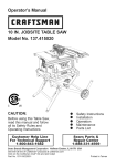
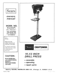
Operator's Manual
3.0 HP (Max. Developed)
10" Inch Blade
5000 R.P.M.
JOBSITE SAW
Model:
137.218240
CAUTION:
Before using this Table Saw,
read this manual and follow
all its Safety Rules and
Operating Instructions
•
•
•
•
•
Customer
Help
1-800-843-1682
Safety Instructions
Installation
Operation
Maintenance
Parts List
Line
Sears, Roebuck and Co., Hoffman Estates, IL 60179 USA
Visit our Craftsman website: www.sears.com/craftsman
Part No. : 137218240001
SECTION
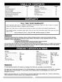
Warranty ........................................
Product Specifications .......................
Power Tool Safety ............................
Table Saw Safety ..............................
Electrical Requirements and Safety ......
Accessories and Attachments ..............
Tools Needed For Assembly ................
Carton Contents ..............................
PAGE
2
2
3
4
5
6
6
6
SECTION
Know Your Table Saw .......................
Assembly and Adjustments .................
Operation .......................................
Maintenance ...................................
Troubleshooting Guide .......................
Parts List ........................................
Push Stick Pattern ...........................
PAGE
8
9
16
20
21
22
30
FULL ONE YEAR WARRANTY
If this Table Saw fails due to a defect
Sears will at its option repair or replace
in material or workmanship
it free of charge.
Return this Table Saw to a Sears Service
This warranty
state to state.
gives you specific
Sears,
Roebuck
within one year of date of purchase,
Center for repair, or to place of purchase
legal rights,
for replacement.
and you may also have other rights which
and Co., Dept. 817 WA, Hoffman
Estates,
may vary from
IL 60179
Some dust created by power sanding, sawing, grinding, drilling and other construction activities contains
chemicals known to the state of California to cause cancer, birth defects or other reproductive harm. Some
examples of these chemicals are:
• Lead from lead-based paints
• Crystalline silica from bricks, cement and other masonry products
• Arsenic and chromium from chemically treated lumber
Your risk from these exposures varies, depending on how often you do this type of work. To reduce your exposure
to these chemicals, work in a well-ventilated area and work with approved safety equipment such as dust masks
that are specially designed to filter out microscopic particles.
•
i
MOTOR
HP (Maximum developed) .....
Type ..................................
Amps .................................
Voltage ..............................
Hz ......................................
RPM (no load) ....................
Overload Protection .............
SAW
3.0
Universal
15
120
60
5000
YES
Table Size ........................
Table Extensions ...............
Extension Rip Capacity...
Blade Size ........................
Rear Outfeed Extension
Rip Fence ........................
Miter Gauge ......................
Maximum Cut Depth @ 90°..
Maximum Cut Depth @ 45°..
Maximum Dado Cut Width...
Net Weight ......................
26" x 18-1/16"
Right - 5-3/4"
24-7/8" Right Rip
10"
YES
YES
YES
3-1/8"
2-5/8"
1/2"
64.5 LBS
To avoid electrical hazards, fire hazards or damage to the table saw, use proper circuit protection.
This table saw is wired at the factory for 110-120 Volt operation. It must be connected to a 110-120 Volt / 15 Ampere
time delay fuse or circuit breaker. To avoid shock or fire, replace power cord immediately if it is worn, cut or
damaged in any way.
Before using your table saw, it is critical that you read and understand these safety rules. Failure to follow these
rules could result in serious injury to you or damage to the table saw.
rules.
Failure
Before using your table saw, it is critical that you read and understand
these safety
to follow these rules could result in serious injury or damage to the table saw.
Good safety practices are a combination of common
sense, staying alert and understanding how to use your
power tool. To avoid mistakes that could cause serious
injury, do not plug in your power tool until you have read
and understood the following safety rules:
1.
.
.
.
.
e.
7.
.
9.
READ and become familiar with this entire
Operator's Manual. LEARN the tool's applications,
limitations and possible hazards.
Look for this symbol that
identifies important safety precautions. It means
CAUTION! Become alert, your safety is involved if
you do not follow the safety instructions.
Look for this symbol that
identifies important safety precautions. It means
CAUTION! Become alert, your safety is involved if
you do not follow the safety instructions.
NEVER OPERATE THIS MACHINE WITHOUT THE
SAFETY GUARD IN PLACE FOR ALL THROUGHSAWING OPERATIONS.
accessories. The use of improper accessories may
cause injury to you or damage to the tool.
16. REMOVE ADJUSTING KEYS AND WRENCHES.
Form the habit of checking to see that keys and
adjusting wrenches are removed from the tool
before turning ON.
17. NEVER LEAVE TOOL RUNNING UNATTENDED.
TURN THE POWER "OFF". Do not leave the tool
before it comes to a complete stop.
18. NEVER STAND ON TOOL. Serious injury could
occur if the tool is tipped or if the cutting tool is
unintentionally contacted.
19. DO NOT OVERREACH.
balance at all times.
Keep proper footing and
20. MAINTAIN TOOLS WITH CARE. Keep tools sharp
and clean for most efficient and safest performance.
Follow instructions for lubricating and changing
accessories.
DO NOT use power tools in the presence of
flammable liquids or gases.
21. CHECK FOR DAMAGED PARTS. Before further
use of the tool, a guard or other part that is damaged
should be carefully checked to ensure it will operate
properly and perform its intended function. Check
for alignment of moving parts, binding of moving
parts, mounting and any other conditions that may
affect its safe operation. A guard or other part that is
damaged should be properly repaired or replaced.
KEEP WORK AREA CLEAN. Cluttered areas and
benches invite accidents.
22. MAKE WORKSHOP CHILD PROOF with padlocks,
master switches or by removing starter keys.
KEEP CHILDREN AWAY. All visitors should be kept
at a safe distance from the work area.
23. DO NOT operate the tool if you are under the
influence of any drugs, alcohol or medication that
could impair your ability to use the tool safely.
DO NOT USE IN DANGEROUS ENVIRONMENTS
such as damp or wet locations or exposure to rain.
Keep work area well lighted.
DO NOT FORCE THE TOOL. It will do the job
better and safer at the rate for which it was
designed.
10. USE THE RIGHT TOOL. Don't force the tool or
attachment to do a job for which it is not designed.
11. WEAR PROPER APPAREL. DO NOT wear loose
clothing, gloves, neckties, rings, bracelets or other
jewelry which may get caught in moving parts. Nonslip footwear is recommended. Wear protective hair
covering to contain long hair.
12. WEARA FACE MASK OR DUST MASK. Sawing,
cutting and sanding operations produce dust.
13. DISCONNECT TOOLS before servicing and when
changing accessories such as blades, cutters, etc.
14. REDUCE THE RISK OF UNINTENTIONAL
STARTING. Make sure the switch is in the OFF
position before plugging into the power supply.
15. USE ONLY RECOMMENDED ACCESSORIES.
Consult the Operator's Manual for recommended
24. USE A DUST COLLECTION SYSTEM wherever
possible. Dust generated from certain materials can
be hazardous to your health and in some cases, a
fire hazard. Always operate the power tool in a wellventilated area with adequate dust removal.
25. ALWAYS WEAR EYE PROTECTION. Any power
tool can throw foreign objects into your eyes which
could cause permanent eye damage. ALWAYS wear
safety goggles (not glasses) that comply with ANSI
safety standard Z87.1. Everyday glasses have only
impact resistant lenses. They ARE NOT safety
glasses.
NOTE: Glasses or goggles not in compliance with
ANSI Z87.1 could cause serious injury when they
break.
26. DIRECTION OF FEED. Feed work into a blade or
cutter against the direction of rotation of the blade or
cutter only.
27. DO NOT AUTHORZE ADDITIONAL USERS to
operate this power tool without the accompanying
operators manual for which the user must read &
understand.
ALWAYS USE SAW BLADE GUARD, splitter and
anti-kickback pawls for every operation for which they
can be used, including through-sawing. Throughsawing operations are those in which the blade cuts
completely through the workpiece when ripping or
cross-cutting.
.
.
.
ALWAYS HOLD WORK FIRMLY against the miter
gauge or rip fence.
USE A PUSH STICK when required. Always use a
push stick when ripping narrow stock. Refer to
ripping instructions in this Operator's Manual where
the push stick is covered in detail. A pattern for
making your own push stick is included on page 30.
NEVER PERFORM ANY OPERATION "FREE
HAND", which means using only your hands to
support or guide the workpiece. Always use either the
fence or the miter gauge to position and guide the
work.
DANGER: FREEHAND CUTTING IS THE MAJOR
CAUSE OF KICK-BACK & FINGER/HAND
AMPUTATIONS.
.
NEVER STAND or have any part of your body in line
with the path of the saw blade. Keep your hands out
of the saw blade path.
.
NEVER REACH behind or over the cutting tool for
any reason.
7.
NEVER use a rip fence when cross cutting.
8.
DO NOT USE a molding head with this saw.
9.
FEED WORK INTO THE BLADE against the
direction of rotation only.
10. NEVER use the rip fence as a cut-off gauge when
cross-cutting.
11. NEVER ATTEMPT TO FREE A STALLED SAW
BLADE without first turning the saw OFF. Turn
power switch OFF and disconnect the plug from the
power source immediately to prevent motor damage
& before removing material
12. PROVIDE ADEQUATE SUPPORT to the rear and
the sides of the saw table for long or wide
workpieces.
13. AVOID KICKBACKS (work thrown back towards
you) by keeping the blade sharp, the rip fence
parallel to the saw blade and by keeping the splitter,
anti-kickback pawls and guards in place and
functioning. Do not release work before it has
passed all the way past the saw blade & is off the
table. Do not rip work that is twisted, warped or does
not have a straight edge to guide it along the fence.
14. AVOID AWKWARD OPERATIONS and hand
positions where a sudden slip could cause your hand
to move into the saw blade.
15. NEVER
Solvents
damage
be used
USE SOLVENTS to clean plastic parts.
could possibly dissolve or otherwise
the material. Only a soft damp cloth should
to clean plastic parts.
16. MOUNT your table saw on a bench or stand before
performing any cutting operations. Refer to
ASSEMBLY AND ADJUSTMENTS on page 9.
17. NEVER CUT METALS or materials which may make
hazardous dust.
18. ALWAYS USE IN WELL-VENTILATED
AREA.
Remove sawdust frequently. Clean out sawdust from
the interior of the saw to prevent a potential fire
hazard. Attach a vacuum to the dust port for
additional sawdust removal.
19. NEVER LEAVE THE SAW running unattended. Do
not leave the saw until it comes to a complete stop.
20. FOR proper operation follow the instructions in this
Operator's Manual. Failure to provide sawdust fallthrough and removal hole will allow sawdust to build
up in the motor area resulting in a fire hazard and
potential motor damage (see page 10 for details).
21. DO NOT AUTHORIZE ADDITIONAL USERS to
operate this power tool without the accompanying
operators manual for which the user must read and
understand.
22. THE REAR OF THE TABLE INSERT MUST BE
FLUSH TO THE TABLE during all sawing
operations. Two different inserts are provided for
regular through-sawing operations and dado cutting
where a rubber adjusting spacer is provided under
the rear of the insert for this purpose.
23. DO NOT USE A DADO BLADE LARGER THAN 6"
in diameter and ½" in width.
POWER
SUPPLY
REQUIREMENTS
GROUNDING
To avoid electrical hazards, fire hazards or damage to
the table saw, use proper circuit protection. Always
use a separate electrical circuit for your tools. This
power tool is wired at the factory for 120V operation.
Connect it to a 120V, 15 Amp circuit and use a 15
Amp time delay fuse or circuit breaker. To avoid
shock or fire, replace the cord immediately if it is
worn, cut or damaged in any way.
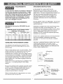
EXTENSION
Any extension cord must be GROUNDED for safe
operation.
MINIMUM GAUGE FOR EXTENSION CORDS
(AWG type / 120 Volt only)
Total length in feet
25'
18
18
16
50'
16
16
16
100'
16
14
14
IN THE EVENT OF A MALFUNCTION OR
BREAKDOWN, grounding provides a path of least
resistance for electric current and reduces the risk of
electric shock. This saw is equipped with an electric cord
that has an equipment grounding conductor and a
grounding plug. The plug MUST be plugged into a
matching receptacle that is properly installed and
grounded in accordance with ALL local codes and
ordinances.
DO NOT MODIFY THE PLUG PROVIDED. If it will not fit
the receptacle, have the proper receptacle installed by a
qualified electrician.
CORD REQUIREMENTS
Ampere Rating
Not
More Than
More Than
0
6
6
10
10
12
INSTRUCTIONS
IMPROPER CONNECTION of the equipment grounding
conductor can result in risk of electric shock. The
conductor (wire) with the green insulation (with or without
yellow stripes) is the equipment grounding conductor, tf
repair or replacement of the electric cord or plug is
necessary, DO NOT connect the equipment grounding
conductor to a live terminal.
150'
14
12
12
CHECK with a qualified electrician or service personnel if
you do not completely understand the grounding
instructions, or if you are not sure the saw is properly
@@iii@_i@iiii_i!liiii!liiii!liiii!!
iii}iiiil£{i_:_iiliii!i
ii@iii_i:i:i:ii!ili
i}ii!ili!_i_i_i_tt!i_!_ii_:iii
grounded.
GUIDELINES
FOR EXTENSION
CORDS
Any extension cord used for power tools MUST be
grounded (3 wire with two flat prongs and one round
ground prong).
Make sure the extension cord is in good condition. When
using an extension cord, make sure you use one heavy
enough to carry the current the tool will draw. An
undersized cord will cause a drop in line voltage resulting
in loss of power and overheating. The table above shows
the correct size to use according to extension cord length
and nameplate ampere rating. If in doubt, use the next
heavier gauge cord. The smaller the gauge number the
heavier the cord.
NOTE: THE 12 TO 16 AMP RATING IS CORRECT FOR
THIS TOOL. IT IS HIGHLIGHTED IN THE TABLE
ABOVE.
Be sure your extension cord is properly wired and in good
condition. Always replace a damaged extension cord or
have it repaired by a qualified person before using it.
Protect your extension cords from sharp objects,
excessive heat and damp or wet areas.
Before connecting the saw to the extension cord, make
sure the saw switch is turned OFF.
USE ONLY 3-WIRE EXTENSION CORDS THAT HAVE
3-PRONG GROUNDING PLUGS AND 3-POLE
GROUNDING RECEPTACLES THAT ACCEPT THE
SAW'S PLUG. REPAIR OR REPLACE DAMAGED OR
WORN CORDS IMMEDIATELY.
3-Prong Plug
Properly Grounded
3*Prong Receptacle
Make Sure This
is Connected to a
Known Ground
"" 2-Prong
Receptacle
RECOMMENDED
ACCESSORIES
Visit your Sears Hardware Department or see the
Craftsman Power and Hand Tools Catalog to purchase
recommended accessories for this power tool.
To avoid the risk of personal injury:
• Do not use adjustable (wobble) type dadoes or
carbide tipped dado blades.
• Maximum dado width is 1/2".
• Do not use a dado with a diameter larger than 6".
• Do not use molding head set with this saw.
• Do not modify this power tool or use accessories not
recommended by Sears.
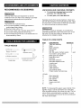
UNPACKING
Medi_m
NEEDED
screwddve_
Adiustabte
w_'ench
#2 Phillips screwdt vet
Straight edge
Combination
squa{e
CHECKING
CONTENTS
For missing or damaged parts on initial
purchase, call 1-800-843-1682
•
To order parts, call 1-800-366-7278
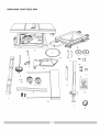
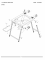
Separate all parts from packing materials. Check each
part with the illustration on the next page and the "Table
of Loose Parts" to make certain all items are accounted
for, before discarding any packing material.
If any part is missing or damaged, do not attempt to
assemble the table saw, plug in the power cord, or turn
the switch ON until the missing or damaged part is
obtained and is installed correctly.
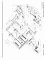
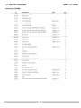
TABLE
TOOLS
AND
•
ITEM
A.
B.
C.
D.
E.
F.
G.
H.
I.
J.
K.
L.
M.
N.
O.
P.
Q.
STAND:
R.
S.
T.
U.
V.
W.
OF LOOSE PARTS
DESCRIPTION
QUANTITY
Table saw assembly
1
Blade
1
Blade wrenches
2
Miter gauge
1
Hex key
1
Bolt, flat washer, toothed washer,
1 each
Oval washer, spring washer
Blade guard and splitter
1
Dado table insert
1
Rip fence
1
Rear table extension
1
Rear table extension tube
2
Location seat
4
Dome nuts
2
Hand wheels
2
Table extension
1
Dust collector elbow
1
Parallel washer hardware bag
1
Stand assembly
Hex. head bolts
Flat washers
Roller wheels
Square neck bolts
Nuts
1
4
4
2
2
2
NOTE: To make assembly easier, keep contents of box
together. Apply a coat of automobile wax to the table.
Wipe all parts thoroughly with a clean dry cloth. This will
reduce friction when pushing the workpeice. To avoid
injury, the styrofoam block should be removed between
the motor and the table.
UNPACKING
YOUR TABLE
SAW
3
B
C
W
_Q
D
S
T
OO
M
K
==a
L
O
@
P
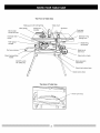
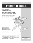
TheFrontof TableSaw
Blade
guard
Miter gauge
with LED lighting
Cutting line
indicator
Table
insert
Rip fence
Side table
_xtension
X
Bevel angle
Pointer & scale
Extension wing
locking lever
Overload reset
switch
._-----
Miter gauge
storage
Blade tilting
handwheel
Blade
Rip fence
storacie
bevel
lock knob
Stand
roller wheels
Stand transportation
handle
Blade elevation
handwheel
ON/OFF switch
with safety key
Stand
Stand
Leq Lock nq lever
Iockinq
hook
The Rear of Table Saw
j
/
Power
cord wrap
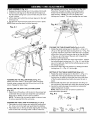
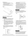
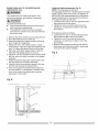
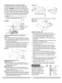
STAND ASSEMBLY (Fig. A-l)
1. Release the stand locking hook (1) by sliding it to the left.
2. Unfold the wider leg set on the left side of the stand (2).
Pull the stand locking lever (3) downward and push down
to lock in place.
3. Lift the stand and unfold the narrower leg set on the right
of the saw (4).
4. Pull the lever downward and push down to lock in place.
NOTE:Make sure the stand is locked securely.
flat washers onto four hex. head bolts (1) - (Fig. A-2).
Place them through the base mounting holes and
thread into the stand mounting and tighten all four
bolts securely. NOTE: Do not over tighten bolts
holding saw to stand. This may damage the saw base.
Fig. A-2
Fig. A-1
1
1
8
7
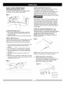
FOLDING THE TABLE SAW/STAND (Fig. A-l, A-3)
1. Rotate the stand locking lever to the left (1) - (Fig. A-1 ).
Lift up on the right side stand locking lever (2) - (Fig. A-2)
to unlock and lift the right side of the table saw up slightly
off the floor, fold up the narrower leg set on the right side
of the saw up to the base of the saw until it snaps into
position on the spring clip.
2. Rest the right side of the saw back onto the floor, release
the left side stand locking lever (3) - (Fig. A-l) and tilt the
saw on its right side, then fold the left side leg set up into
the storage position.
3. Secure the stand legs into position by rotating the stand
locking lever (1) - (Fig. A-l) to the right.
SETTING UP THE TABLE SAW/STAND (Fig. A-3)
1. Rotate the stand locking lever to the left (1) - (Fig. A-1 ).
2. Unfold the wider leg set (left side) and lock the stand
locking lever in place by sliding the lever down the slots
of the mounting bracket and push downward to lock in
place.
3. Rest the left side of the saw onto the floor and lift up on
the right side of the stand and unfold the narrower leg set.
4. Secure the right side legs into position by locking the
stand locking lever in place.
NOTE: Make sure the saw is locked in position as
instructed before operation.
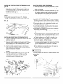
ASSEMBLING THE ROLLER WHEELS (Fig. A-l)
Attach one roller wheel (7) to the roller wheel mounting
bracket using a square neck bolt (8) and lock nut (9) as
shown. Repeat for other wheel.
INSTALLING THE DUST COLLECTION ELBOW
(Fig. A-l)
1. Align the lip of the elbow with the slot on the exhaust por
underneath the saw base and install the dust collection
elbow (6) by rotating ¼ turn to lock in position.
NOTE: The elbow can be used to attach a vacuum hose
to remove sawdust from the work area.
Fig. A-3
ASSEMBLING TABLE SAW TO STAND (Fig. A-1,A-2)
1. Place stand on level surface and adjust the leveling foot
(5) - (Fig. A-2) on the right rear leg of stand to stabilize.
2. Place table saw on the top of stand aligning the mounting
holes in base with mounting holes in stand. Place four
_OLD_NG
SET-UP
9
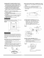
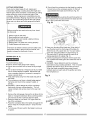
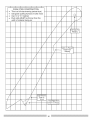
SAW MOUNTED TO WORK SURFACE (FIG. B)
1. If the leg set will not be used, the saw must be
properly secured to a sturdy workbench using the
four mounting holes at the base of the saw.
2. The surface of the table where the saw is to be
mounted must have a hole large enough to
facilitate sawdust fall-through and removal.
3. Square the saw on the mounting surface and
mark the location of the four 3/8" mounting holes
(1).
4. Drill 3/8" hole into the mounting surface.
5. Mark an 11" square (2) centered between the four
mounting holes (1).
6. Cut out and remove the square.
7. This opening will allow sawdust to fall through the
saw base.
8. Place the saw on the work surface, and align the
mounting holes of the saw with those drilled
through the surface.
9. Fasten the saw to the work surface.
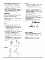
INSTALLING BATTERY FOR LED WORKLIGHT (FIG.D)
1. Open the cover (1) of the battery box on the top of blade
guard.
2. Install two 1.5V - 3A batteries into the battery box.
3. Secure the cover into the closed position.
4. Turn the on/off switch (2) to the on position to display
the LED light.
Fig. D
/
BLADE RAISING HANDWHEEL (FIG. E, F)
1. Attach the up ~ down handwheel (1) to the
elevation rod (2) at the front of the saw.
Make sure the slots (3) in the hub of the
handwheel engage with the pins (4).
2. Attach and tighten the dome nut (5 - Fig. F).
Do not operate this machine on the floor. This is very
dangerous and may cause serious injury.
Fig. B
Fig. E
2
3
Failure to provide the sawdust fall-through hole for
use of the saw when mounted to a work surface and
2
4
1
not the stand will cause sawdust to build up in the
motor area, which may result in fire or cause motor
damage.
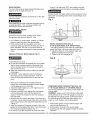
BLADE TILTING HANDWHEEL (FIG. F)
1. Attach the bevel 0 ° ~ 45 ° handwheel (6) to the
blade tilting rod on the right side of the saw in
the same manner as above.
2. Attach and tighten the handwheel dome nut (5).
ADJUSTING THE CUT LINE INDICATOR (FIG.C)
1. Remove the indicator cover (1) and the two
mounting screws (2).
2. Adjust the indicator to the desired position (3) to
align with the blade.
3. Replace the cover onto the table and replace the
two screws to affix the indicator in position.
NOTE:The cut line indicator was set up at the factory
to be positioned to the right side of the saw blade.
Fig. F
Fig. C
1
2
10
RIP FENCE (Fig. G)
1. Lift upward on the rip fence handle (1) so the
rear clamp (2) is fully extended.
2. Place the rip fence on the saw table by engaging
the front of the rip fence first
3. Lower the rear of the fence onto the table.
4. Push down on the fence handle to lock in place.
3.
4.
5.
Fig. G
6.
2
height by turning the blade raising handwheel
counterclockwise.
Place the open-end wrench jaws on the fiats of
the saw arbor to keep the arbor from turning. (Fig.
J) and place the box-end wrench (8) on the arbor
nut (5), and turn counterclockwise.
Remove the arbor nut (5) and outer flange (6).
Install the saw blade onto the arbor with the blade
teeth pointing toward the front of the saw.
Install the flange (6) against the blade and thread
the arbor nut (5) as far as possible by hand.
Ensure that the blade is flush against the inner
side of the blade flange.
To avoid possible injury and damage to the
workpiece be sure to install the blade with the teeth
pointing toward the front of table in the direction of
the rotation arrow on the blade guard.
Fig. I
5
3
INSTALLING AND CHANGING THE BLADE
(FIG. H, I, J)
To avoid injury from an accidental start, make
sure the switch is in the OFF position and the
plug is not connected to the power source
outlet.
To avoid serious injury, table insert must be
level with the table, tf the table insert is not
level with the table, adjust the screw (3) until it
is level with the table. To raise the insert, turn
the screw counterclockwise, to lower the insert,
turn the screw clockwise. Note: A rubber
adjusting spacer is provided under rear of
insert for this purpose.
1. Remove the table insert (1 by removing the two
screws (2, 3). Be careful not to lose the rubber
washer that is on the back screw (3) beneath the
table insert. (Fig. H)
To tighten the arbor nut (5) place the open-end
wrench jaws on the fiats of the saw arbor to keep
the arbor from turning. (Fig. J)
. Place the box-end wrench
(9) on the arbor nut (5),
and turn clockwise (to the rear of the saw table).
9. Replace the blade insert in the table recess, insert
the screws through the front and rear holes and
tighten remembering the rubber washer under the
rear of the insert..
.
Fig. J
Fig. H
To avoid injury from a thrown workpiece, blade parts,
or blade contact, never operate saw without the
proper insert in place. Use the original installed
insert for all sawing operations except dado cuts.
Use the dado head insert when using a dado.
2. Raise the blade arbor (4) (Fig. l) to the maximum
11
BLADE
GUARD
ASgEMBLY
[F_G
K. U M
_:_-
_
.........
i!
J
• _
.... .=,= .........
_.........
=,.
..
.............
4 ;_:.
)
°
INSTALLING THE TABLE SIDE EXTENSIONS-
cont'd
(FIG O)
6. Snap one location seat (5) over the end of the rear
table extension tube (3). Make sure the locating pin
(6) in the location seat fits into the matching hole in
the extension tube (Fig. O).
7. Install the left hand table extension in a similar way.
NOTE:
For illustration purposes the view in Fig. O looks
"through" the saw table to the under side of the table.
Fig. O
INSTALLING REAR TABLE EXTENSION (FIG. P)
1. Place the rear table extension onto the two rear table
extension tubes (1).
2. Snap two location seats (4) over the two rear table
extension tubes (1).Make sure the locating pin in the
location seat fits into the matching hole (5) in the
extension tube.
3. Insert rear table extension tubes (1) into the two
holes in the rear of the saw table and into extension
tube brackets under the table.
Position rear table support so instruction labels
are up.
4. Snap one location seat (4) over the end of the left
rear table extension tube (1). Make sure the
locating pin in the location seat fits into the
matching hole in the extension tube.
ADJUSTING
REAR TABLE EXTENSION
1. Rear table extension should be positioned as close
2.
as possible to the rear of the table when ripping
short work pieces.
Rear table extension should be pulled out fully until
the location seat prevents it from moving outward
when ripping long work pieces that require extra
support as you are completing the cut.
RIP FENCE ADJUSTMENT
(FIG. Q)
1. The fence (1) is moved by lifting up on the handle (2)
and sliding the fence to the desired location. Pushing
down on the handle locks the fence in position.
2. Position the fence on the right side of the table, and
along the miter gauge groove.
3. Lock the fence handle. The fence should be parallel
with the miter gauge groove.
4. If adjustment is needed to make the fence parallel to
the groove, do the following:
• Loosen the two screws (3) and lift up on the handle
(2).
• Hold the fence bracket (4) firmly against the front of
the saw table. Move the far end of the fence until it
is parallel with the miter gauge groove.
• Tighten both screws and push the handle to lock.
5. If fence is loose when the handle is in the locked
(downward) position, do the following:
• Move the handle (2) upward and turn the adjusting
nut (5) clockwise until the rear clamp is snug. Do not
turn the adjusting screw more than 1/4 turn at a
time.
• Over-tightening the adjusting screw will cause the
fence to come out of alignment.
I,A WARNING l
Failure to properly align fence can cause "kickback" and
serious injury.
Fig. Q
Fig. P
4 3
5
6
2
RIP FENCE INDICATOR ADJUSTMENT (FIG. P)
1. The rip fence indicator (6) points to the
measurement scale (8). The scale shows the
distance between the fence and the blade.
2. Measure the actual distance with a rule. If there is
a difference between the measurement and the
indicator, adjust the indicator (6).
3. Loosen the screw (7) and slide the indicator to the
correct measurement on the scale. Tighten the
screw and re-measure with the rule.
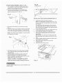
45 ° Stop
1. With the blade in the upright 90 ° position, loosen
the bevel lock knob and move the blade to the
45 ° position as far as it will go.
2. Place the combination square on the table as
shown in (Fig.Q-2) to check if the blade is 45 ° to
the table.
3. If the blade is not 45 ° to the table, loosen the two
set screws (4), located on the collar (5)
underneath the table saw, (Fig. Q-3) with the hex
key, and back off the collar.
4. Tighten the bevel lock knob & secure the screw
(4) until resistance is felt. Do not overtighten.
BLADE TILT POINTER
1. When the blade is positioned at 90 °, adjust the
blade tilt pointer to read 0 ° on the scale.
2. Loosen the mounting screw, position pointer over
0 ° and tighten the screw.
NOTE: Make a trial cut on scrap wood before
making critical cuts. Measure for exactness.
To avoid injury from an accidental start, make sure
the switch is in the OFF position and the plug is not
connected to the power source outlet.
ADJUSTING THE 90 ° AND 45 ° POSITIVE STOPS
(FIG.Q-I, Q-2, Q-3)
Your saw has positive stops that will quickly position
the saw blade at 90 ° to the table. Make adjustments
only if necessary.
Fig. Q-3
90 ° Stop
1. Disconnect the saw from the power source.
2. Turn the blade elevation handwheel and raise
the blade to the maximum elevation.
3. Loosen the blade bevel lock knob (2) and move
the blade to the maximum vertical position, then
tighten the lock knob (2).
4. Place a combination square on the table and
against the blade (1) to determine if the blade is
90 ° to the table. (Fig. Q-2)
5. If the blade is not 90 ° to the table, loosen the two
set screws (4), located on the collar (5)
underneath the table saw, (Fig. Q-3) with the
hex key, and back off the collar..
6. Loosen the bevel lock knob. Turn the blade
tilting handwheel to move the blade until it is 90 °
to the table.
7. Adjust the collar (5) so it contacts the bracket (3)
when the blade is 90 ° to the table. Tighten the
two set screws (4) (Fig.Q-3).
345
BLADE TILT POINTER
3. When the blade is positioned at 90 °, adjust the
blade tilt pointer to read 0 ° on the scale.
4. Loosen the holding screw, position pointer over 0 °
and tighten the screw.
NOTE: Make a trial cut on scrap wood before
making critical cuts. Measure for exactness.
Fig. Q-1
Fig. Q-2
90 °
....._-._
_
45 °
::......
14
BLADE PARALLEL TO THE MITER GAUGE
GROOVE (FIG. R,S)
Additional blade adjustments (Fig. S)
NOTE: The adjusting nuts are 8mm.
The adjusting mechanism is located above the blade
height adjusting hand wheel under the tabletop. If
the front and rear measurements are not the same,
adjust the alignment by the mechanism as follows:
If the blade is partial to right side:
1. Loosen the two nuts (1) and the right side screw,
then adjust the left side screw.
2. Tighten the nuts (1) and the right screw and
remeasure, as described in steps 4 to 9 in the
prior section.
WARNING I
This adjustment was made at the factory, but it
should be rechecked and adjusted if necessary.
WARNING]
To prevent personal injury:
•
Always disconnect plug from the power source
when making any adjustments.
•
This adjustment must be correct or kickback
could result in a serious injury and accurate cuts
can not be made.
If the blade is partial to left side:
3. Loosen the two nuts (1) and the left side screw,
then adjust the right screw to its position.
4. Tighten the nuts (1) and the left screw and
remeasure, as described in steps 4 to 9 in the
prior section.
5. Recheck blade clearance making sure that the
blade does not hit the table insert or other parts
when at the 90 ° and 45 ° settings.
1. Remove the yellow switch key and unplug the saw.
2. Move the blade guard out of the way.
3. Raise the blade to the highest position and set at
the 0° angle (90 ° straight up).
4. Select and mark, with a felt tip marker, a blade
tooth having a "right set" angle and positioning this
tooth 1/2" above the table at the front of the saw.
5. Place the combination square base (1) into the
right side miter gauge groove (2). (Fig. R)
6. Adjust the rule so it touches the front marked tooth
and lock ruler so it holds its position in the square
assembly.
7. Rotate the blade bringing the marked tooth to the
rear and about 1/2 inch above the blade.
8. Carefully slide the combination square to the rear
until the ruler touches the marked tooth.
9. If the ruler touches the marked tooth at the front
and rear position, no adjustment is needed at this
time. If not, perform the adjustment procedure
described in next section.
Fig. S
Fig. R
2
15
BASIC SAW OPERATIONS
ADJUSTING BLADE HEIGHT (FIG. T)
To raise or lower the blade, turn the blade elevation
handwheel (1) to the desired blade height.
Fig. T
3
1
2
TILTING THE BLADE (FIG. T)
1. To tilt the saw blade for bevel cutting, loosen the
lock knob (2) and turn the tilting handwheel (3) to
the desired angle.
2. Tighten the bevel lock knob (2) to secure the angle.
ON/OFF SWITCH (FIG. U)
The ON / OFF switch has a removable safety key. With
the key removed from the switch, unauthorized and
hazardous use by children and others is minimized.
1. To turn the saw ON, insert key (1) into the slot in the
switch (2). Move the switch upward to the ON
position.
2. To turn the saw OFF, move the switch downward.
3. To lock the switch in the OFF position, grasp the
end of the toggle switch (1) and pull out the safety
switch key.
4. With the switch key removed, the switch will not
operate.
5. If the switch key is removed while the saw is running,
it can be turned OFF but cannot be restarted without
inserting the switch key (1).
Fig. U
OVERLOAD PROTECTION (FIG. V)
This saw has a reset overload relay button (3) that
will restart the motor after it shuts off due to
overloading or low voltage, tf the motor stops during
operation, turn the ON / OFF switch to the OFF
position. Wait for the motor to cool. Push in on the
reset button (3) and turn the switch to the ON position.
To avoid injury, the ON / OFF switch must be in the
OFF position and the plug removed from the power
source while the cool down takes place, to prevent
accidental starting when the reset button is pushed.
Overheating may be caused by misaligned parts or a
dull blade. Inspect your saw for proper setup before
using it again.
USING THE TABLE EXTENSION (FIG. V, V-l)
If the table extension is not parallel with the table.
Remove the bolts (1) and position the parallel washers
(2) between the table extension and tube until it is
parallel with the table, then tighten the bolts.
NOTE: Parallel washer (2) see page 6 for table of
loose parts ITEM: Q.
Fig. V
_,_
NOTE: Move and lock the fence to the 15" left or right
side scale. The fence is now clear of the table.
1.
2.
3.
Release the extension lock handles.
Slide the extension out until the correct
measurement is displayed on the tube scale. The
user sights the scale off the edge of the table.
Tighten both extension lock handles.
3
Fig. V-1
CUTTING OPERATIONS
There are two basic types of cuts: ripping and
crosscutting. Ripping is cutting along the length and
with the grain of the workpiece. Crosscutting is cutting
either across the width or across the grain of the
workpiece. Neither ripping nor crosscutting may be
done safely freehand. Ripping requires the use of the
rip fence, and crosscutting requires the miter gauge.
Never use a rip fence and miter gauge at the same
time.
5. Slowly feed the workpiece into the blade by pushing
forward only on the workpiece section (1) that will
pass between the blade and the fence. (Fig. W)
AVOID KICKBACK by pushing forward that section of
the workpiece that will pass between the blade and the
fence. Use a push stick at all times.
Fig. W
Before using the saw each and every time, check
the following:
1. Blade is tight on the arbor.
2. Bevel angle lock knob is tight.
3. If ripping, fence lock handle is tight and fence
is parallel to the blade.
4. Blade guard is in place and working properly.
5. Safety glasses are being worn.
The failure to adhere to these common safety rules,
and those printed in the front of this manual, can
greatly increase the likelihood of injury.
RIPPING(FIG.
W,X)
To prevent serious injury:
• Never use the miter gauge when ripping.
• Never use more than one rip fence during a single
cut.
• Do not allow familiarity or frequent use of your table
saw to cause careless mistakes. Remember that
even a careless fraction of a second is enough to
cause a severe injury.
• Keep both hands away from the blade and path of
the blade.
• The workpiece must have a straight edge against
the fence and must not be warped, twisted, or
bowed.
• DANGER - Never attempt to pull the workpiece
backwards during a cutting operation. This will
cause kickback and serious injury to the user can
occur.
1. Remove the miter gauge. Secure the rip fence to the
table or if using the extension fence, set the position
and remove all other rip fences from the table..
2. Raise the blade so it is about 1/8" higher than the
top of the workpiece.
3. Place the workpiece flat on the table and against the
fence. Keep the workpiece about 1" away from the
blade.
4. Turn the saw ON and wait for the blade to come up
to speed.
6. Keep your thumbs off the blade top. When both of
your thumbs touch the front edge of the table (2),
finish the cut with a push stick (3). You can make a
push stick using the pattern on page 30 (Fig. X).
7. The push stick (3) should always be used for all
ripping operations for safety (Fig. X).
8. Continue pushing the workpiece with the push stick
until it passes the blade guard and clears the rear of
the table.
9. DANGER - Never attempt to pull the workpiece
backwards during a cutting operation. This will cause
kickback and serious injury to the user can occur.
When the blade completely stops raise the antikickback pawls on each side of the splitter and slide
the workpiece out.
Fig. X
BEVEL RIPPING
This cut is the same as ripped except the blade bevel
angle is set to an angle other than "0".
turning. Turn the switch OFF, and carefully slide the
)iece out when the blade is completely stopped.
Always position the larger surface of the workpiece on the
table when crosscutting and/or bevel crosscutting to avoid
unstability.
Cut only with the workpiece and the fence on the right
side of the blade.
Fig. Y
Never attempt to pull the workpiece backwards during
a cutting operation. This will cause kickback and
serious injury to the user can occur.
3
2
RIPPING SMALL PIECES
Avoid injury from the blade contact. Never make
through-saw cuts narrower than 3/4" wide.
1. It is unsafe to rip small pieces. Instead, rip a larger
piece to obtain the size of the desired piece.
2. When a small width is to be ripped, your hand
cannot be safely put between the blade and the rip
fence, therefore, use one or more push sticks to
pass the workpiece completely through and past the
blade.
CROSSCUTTING
BEVEL CROSSCUTTING (FIG. Z)
0°-45 ° BLADE BEVEL & 90 ° MITER ANGLE
This cutting operation is the same as crosscutting
except the blade is at bevel angle other than 0 °.
1. Adjust the blade (1) to the desired angle, and
tighten the blade bevel lock knob.
2. Tighten miter lock handle at 90.
90 ° MITER ANGLE (FIG. Y)
Fig. Z
3
To prevent serious injury:
• Do not allow familiarity or frequent use of your table
saw to cause careless mistakes. Remember that
even a careless fraction of a second is enough to
cause a severe injury.
• Keep both hands away from the blade and the path
of the blade.
• DANGER - Never attempt to pull the workpiece
backwards during a cutting operation. This will
cause kickback and serious injury to the user can
occur.
2
1. Remove the rip fence lower all table extension
fences flush to the table and place the miter gauge
a miter gauge groove on the table.
2. Adjust the blade height so it is 1/8" higher than the
top of the workpiece.
3. Hold the workpiece firmly against the miter gauge
with the blade path in line with the desired cut
location. Move the workpiece to one inch distance
from the blade.
4. Start the saw and wait for the blade (1) to come up to
full speed. Never stand directly inline of the saw blade
path, always stand to the side of the blade that you are
cutting on.
5. Keep the workpiece (2) against the face of the miter
gauge (3) and flat against the table. Then slowly push
the workpiece through the blade. (Fig. Y)
6. Do not try to pull the workpiece back with the blade
18
COMPOUND MITER CROSSCUTTING (FIG. AA)
00-45 ° BLADE BEVEL & 00-45 ° MITER ANGLE
This sawing operation is combining a miter angle with
a bevel angle.
WARNING - Always work to the left side of the blade
during this type of cut. The miter gauge (3) must be in
the left side miter gauge groove. It cannot be used in
the right side groove unless the miter angle is very
sharp, as it will interfere with the blade guard.
1. Set the miter gauge (3) to the desired angle. Use
only the left side groove (2).
2. Set the blade (1) bevel to the desired angle.
3. Carefully push the miter gauge to begin the cutting
operation.
MITERING (FIG. BB) 00-45 ° MITER ANGLE
This sawing operation is the same as crosscutting
except the miter gauge is locked at an angle other
than 90 °. WARNING - Always work to the left side of
the blade during this type of cut. The miter gauge (3)
must be in the left side miter gauge groove. It cannot
be used in the right side groove unless the miter angle
is very sharp, as it will interfere with the blade guard.
1. Hold the workpiece (2) firmly against the miter
gauge (3).
2. Feed the workpiece slowly into the blade (1) to
prevent the workpiece from moving.
Fig. CC-1
30"
_:"
_-
3/8 _ Thick
plywood
_
IF_
base
¢o
3/4"
Thick
27"
pIywood
side
I__
Attach auxiliary fence to rip fence with two "C" clamps.
(Fig. CC-2)
Fig. CC-2
USING WOOD FACING ON THE RIP FENCE
(FIG. CC)
When performing special cutting operations, you can
add a wood facing (1) to either side of the rip fence (2).
1. Use a smooth straight 3/4" thick wood board (1) that
is as long as the rip fence.
2. Attach the wood facing to the fence with wood screw
(3) through the hole in the fence. A wood fence
should be used when ripping material such as thin
paneling to prevent the material from catching
between the bottom of the fence and the table.
Fig. CC
AUXILIARY FENCE (FIG. CC-1)
_ _"
Making the base:
• Start with a piece of 3/8" plywood at least 5-1/2"
wide or wider and 30" long or longer & cut the piece
to shape and size shown.
Making the side:
• Start with a piece of 3/4" plywood at least 2-3/8"
wide or wider and 27" long or longer & cut the piece
to shape and size shown.
• Assembly the pieces together as shown.
• Make sure the screw heads do not stick out from the
bottom of the base, they must be flush or recessed.
The bottom must be flat and smooth enough to rest
on the saw table without rocking.
DADO CUTS (FIG. DD)
1. The dado table insert is included with this saw.
Remove saw blade and blade guard for dado cuts
only. Reinstall and realign blade guard for all
through sawing operations. Install a dado not
exceeding 6" diameter and ½" width and the dado
table insert.
2. Instruction for operating the dado is packed with the
separately purchased dado set.
3. The arbor (1) on this saw restricts the maximum
width of the cut to 1/2".
4. It is not necessary to install the outside flange (2)
before threading on the arbor nut (3) for maximum
½" dado cuts. Make sure that the arbor nut (3) is
tight, and that at least one thread of the arbor sticks
out past the nut.
5. Use only the 6" diameter dado set and keep the
width 1/2" or less. It will be necessary to remove the
blade guard and splitter when using a dado blade
only. Always use caution when operating a dado
blade.
6. Use only the correct number of round outside blades
and inside chippers as shown in the dado set's
instruction manual. Blades/chippers must not
exceed 1/2" total in width.
7. Check saw to ensure that the dado will not strike
the housing, insert, or motor when in operation.
For your
own safety, always replace
the blade, blade guard
assembly, and blade insert
when you are finished with
the dado operation. You
must also realign the blade
guard assembly.
Fig.
DD
j2
J
i
J
1
\
\
\
3
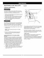
MAINTAINING
GENERAL
YOUR TABLE SAW
Fig. EE
MAINTENANCE
For your own safety, turn the switch OFF and remove
the switch key. Remove the plug from the power source
outlet before maintaining or lubricating your saw.
1. Clean out all sawdust that has accumulated inside the
saw cabinet and the motor.
2. Polish the saw table with an automotive wax to keep
it clean and to make it easier to slide the workpiece.
3. Clean cutting blades with pitch and gum remover.
4. A worn, cut, or damaged power cord should be
replaced immediately.
4
/
All electrical or mechanical repairs should be attempted
only by a trained repair technician. Contact the nearest
Sears Service Center for service. Use only identical
replacement parts. Any other parts may create a hazard.
You can place a small amount of dry lubricant on bevel
andgle adjustment rod also. This rod (1) must be kept
clean and free of sawdust, gum, pitch, and other
contaminants for smooth operation.
5. Use liquid dish washing detergent and water to clean
all plastic parts.
NOTE: Certain cleaning chemicals can damage
plastic parts.
If excessive looseness is observed in any parts of the
blade raising mechanism or tilting mechanism, take the
complete unit to a Sears Service Center.
6. Avoid use of the following cleaning chemicals or
solvents; ammonia and household detergents
containing ammonia.
BLADE RAISING AND TILTING MECHANISM
(FIG. EE)
After each five full hours of operation, the blade raising
mechanism and tilting mechanism should be checked
for looseness, binding, or other abnormalities. With the
saw disconnected from the power source, turn the saw
upside down and alternately pull upward and downward
on the motor unit. Observe any movement of the motor
mounting mechanism. Looseness or play in the blade
raising screw (1) (Fig. EE) should be adjusted as follows:
1. Using a 14mm wrench, loosen the check-nut (2).
2. Adjust nut (3) until it is finger-tight against the
bracket (4), then back off the nut (3) 1/6 turn.
3. Tighten nut (2) with the wrench, while holding nut (3)
in place. Maximum allowable play in and out of the
screw rod (1)is 1/8".
20
LUBRICATION
All motor bearings are permanently lubricated at the
factory and require no additional lubrication.
On all mechanical parts of your table saw where a pivot
or threaded rod are present, lubricate using graphite or
silicone. These dry lubricants will not hold sawdust as
would oil or grease.
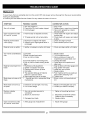
To avoid injury from an accidental start, turn the switch OFF and always remove the plug from the power source before
making any adjustments.
• Consult your local Sears Service Center if for any reason the motor will not run.
SYMPTOM
POSSIBLE CAUSES
CORRECTIVE ACTION
Saw will not start
1. Saw not plugged in
2. Fuse blown or circuit breaker tripped
3. Cord damaged
1. Plug in saw
2. Replace fuse or reset circuit breaker
3. Have cord replaced by a Sears
Service Center
1. Check blade with square and adjust
positive stop
2. Check blade with square and adjust
to zero
1. Check and align rip fence
2. Select another piece of wood
Does not make accurate
45 ° and 90 ° rip cuts
1. Positive stop not adjusted correctly
2. Tilt angle pointer not set accurately
Material pinched blade
when ripping
1. Rip fence not aligned with blade
2. Warped wood, edge against fence is
not straight
Material binds on splitter
1. Splitter not aligned correctly with blade
1. Check and align splitter with blade
Saw makes unsatisfactory
cuts
1. Dull blade
2. Blade mounted backwards
3.Gum or pitch on blade
4. Incorrect blade for work being done
5.Gum or pitch on blade causing erratic
feed
1. Replace blade
2. Turn the blade around
3. Remove blade and clean with
turpentine and coarse steel wool
4. Change the blade
5. Clean table with turpentine and
steel wool
Blade does not raise or tilt
freely
1. Rip fence out of adjustment
2. Splitter not aligned with blade
3. Feeding stock without rip fence
4. Dull blade
5. The operator letting go of material
before it is past saw blade
6. Miter angle lock knob is not tight
1. Sawdust and dirt in raising and tilting
mechanisms
1. Align rip fence with miter gauge slot
2. Align splitter with blade
3. Install and use rip fence
4. Replace blade
5. Push material all the way past saw
blade before releasing work
. Tighten
knob
1. Brush or blow out loose dust and
dirt
Blade does not come up
to speed
1. Extension cord too light or too long
2. Low house voltage
1. Replace with adequate size cord
2. Contact your electric company
Machine vibrates
excessively
Saw not mounted securely to
workbench
2. Bench on uneven floor
2.
3. Damaged saw blade
3.
1. Miter gauge out of adjustment
1. Adjust miter gauge
Material kicked back from
blade
Does not make accurate
45 ° and 90 ° cross cuts
.
.
Tighten all mounting hardware
Reposition on flat level surface
Fasten to floor if necessary
Replace blade
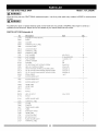
10" JOB SITE TABLE
SAW
Model : 137.218240
WARNING]
When servicing use only CRAFTSMAN
replacement parts. Use of any other parts many create a HAZARD or cause product
damage.
WARNING
J
Any attempt to repair or replace electrical parts on this Table Saw may create a HAZARD unless repair is done by a
qualified service technician. Repair service is available at your nearest Sears Service Center.
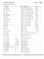
PARTS
LIST FOR Schematic
A
I.D.
Description
2178
0B3H
EXTENTION
INSERT
0B84
WASHER
0B8A
WARNING
0B8F
CAUTION
Size
WING
Qty
(RIGHT)
1
1
1
STICK LABEL
1
LABEL
1
0BC2
LOCATION
SEAT
2
0BD2
WARNING
LABEL
1
0BD3
WARNING
LABEL
0J5L
FLAT WASHER
1
cp5xl 0-0.3
...........................
od.6v.............................
FLATWASHER
0J76
10
3L].6xS4S-o,o22
............................................................
s.................
1
1
1
2
4
2
4
4
1
1
FLAT WASHER
1/4x3/4-1/16
0J95
0JAA
0K8D
0K9U
0KCH
0KCX
0KCY
0KSW
0SZY
SPRING
cp6
0SZZ
SLIDING
BASE ASS'Y
1
0T00
SLIDING
BASE ASS'Y
2
10GN
UPPER TUBE
10GP
UPPER TUBE
20KA
SCALE
1
1
1
20KC
SCALE
1
WASHER
WASHER
cp8
CR. RE.COUNT
HD. TAPPING
HEX. HD. TAPPING
SCREW
SCREW
M4xl
8-16
M5xl
6-25
CR.RE. PAN HEAD TAPPING & WASHER SCREW
M5x0.8-]
CR. RE. PAN HD PLAIN WASHER TAPPING SCREW
M5x0.8-]0
CR. RE. PAN HD PLAIN WASHER TAPPING SCREW
M5x0.8-]
STRAIN RELIEF
SLIDING BASE ASS'Y
20WQ
HEX. HD. BOLT
211Q
SCALE
21HH
MITER GAUGE
22KU
WARNING
237U
COVER
M6x1.0-50
ASS'Y
LABEL
238S
POINTER
26J7
TRADE-MARK
275A
TABLE
275D
EXTENSION
275E
UPPER TUBE
275F
LOCATION
27AD
RIP FENCE ASS'Y
LABEL
WING
SEAT
27AK
BLADE GUARD
27U7
WARNING
q_6.1
ASS'Y
LABEL
2
2
1
1
1
1
1
1
1
1
1
2
2
1
1
1
o
IiI
o
0
rn
-I
llI
r-
rrl
O)
i
I
I
t
\
• +-.+.
I
£I
o
m
==
i,o
/
o
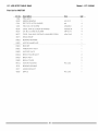
10" JOB SITE TABLE
PARTS
SAW
LIST FOR Schematic
I.D.
2149
2759
Description
KNOB
BODY SHELL
Model : 137.218240
B
Size
Qty
1
1
I.D.
0JVB
0JXL
Description
HEX. SOC. HD. CAP BOLT
HEX. SOC. SETSCREW
Size
M5x0.8-16
M10x1.5-12
Qty
1
1
2771
ANGLE ROD
1
0KOZ
HEX. HD. SCREW AND WASHER
M8x1.25-16
4
08VH
09JK
CLAMP-CORD
WRENCHHEX.
1
1
0K16
0K25
HEX. HD. SCREW AND WASHER
HEX.SOCKET HD.CAP SCREWS
M8x1.25-16
M5x0.8-20
1
1
0B22
HEIGHT REGULATING BOLT
1
0K3G
CR.RE. PAN HD. SCREW & WASHER
M5x0.8-12
1
0B23
SADDLE
1
0K7K
CR. RE. ROUND WASHER HD. SCREW
M6xl.0-12
2
0B24
SPRING
1
0K8C
CR. RE.COUNT HD. TAPPING SCREW
M4x18-10
4
0B27
0B2B
POINTER BRACKET
NEEDLE POINTER
1
1
0K8X
0K9T
CR. RE. TRUSS HD. TAPPING SCREW
HEX. HD. TAPPING SCREW
M5x12-12
M5x16-16
2
6
0B2E
SWITCH BOX
1
0K9U
HEX. HD. TAPPING SCREW
M5xl 6-25
4
0B3K
INSERT
1
0KA4
CR.RE. PAN HD. TAPPING SCREW
M4xl 6-16
2
0B3R
WRENCH
1
0KAP
CR.RE. PAN HD. TAPPING SCREW
M5x0.8-10
1
0B48
WARNING
LABEL
1
0KC8
CR. RE. TRUSSHD. TAPPING SCREW
M4x16-16
2
0B97
MOTOR BRACKET
1
0KDJ
CR. RE. PAN HD. SCREW
M5x0.8-12
2
0B99
SPACER
1
0KDR
CR. RE. PAN HD. SCREW
M5x0.8-10
1
0B9C
PLUNGER HOUSING
1
0KDU
CR. RE. PAN HD. SCREW
M6x1.0-12
2
0B9P
0B9S
CLAMP
BRACKET
2
1
0KF6
0KHZ
CR. RE. PAN HD. SCREW
M4x0.7-8
2
CAP HD. SQ.NECK BOLT
M6x1.0-12
2
0B9W
BRACKET
1
0KJ4
CAP HD. SQ.NECK BOLT
M6x1.0-35
1
0BA4
SPACER
1
0KJ5
CAP HD. SQ.NECK BOLT
M6Xt .0-80
1
0BA9
SPACER
2
0KMR
HEX. NUT
M5x0.8 T=4
1
0BAB
SHIM
1
0KMS
HEX. NUT
M6x1.0 T=5
1
0BAC
SETNUT
1
0KMV
HEX. NUT
M10x1.5 T=8
1
0BAE
0BAT
ARBOR COLLAR
NUT
1
1
0KMW
0KMY
HEX. NUT
M10x1.5 T=4
HEX. NUT
MSx1.25 , T=6.5
1
1
0BAU
SUPPORTING PLATE
1
0KQJ
CROWN NUT
MSx1.25T=I 2.5
2
0BAX
STIFFENER
1
0KRX
HEXAGON NUT AND FLAT WASHER
M6x1.0
2
0BAY
SCREW BAR
1
0KRX
HEXAGON NUT AND FLAT WASHER
M6x1.0
1
0BAZ
BEARING SEAT
1
0KWZ
LEAD WIRE ASS'Y
1
OBB1
SHAFT
1
OLSL
CIRCUIT BREAKER SWITCH
1
0BPA
LOCK KNOB
1
0QEF
MOTOR
1
0J3U
WRENCH HEX.
3-90
1
0S45
ROCKER SWITCH ELEMENT
1
0J4F
FLAT WASHER
cp8X16-2.5
1
0STF
PARALLEL RING ASS'Y
2
0J4H
FLAT WASHER
cpl0x30-0.2
2
0T04
CLAMP ASS'Y
1
0J6T
FLAT WASHER
3/16x3/4-1/16
4
232Z
STICKER ASS'Y
1
0J6U
0J70
FLAT WASHER
FLAT WASHER
3/16xl/2-3/64
1/4x3/4-7/64
1
23PP
BLADE
1
0J76
0J80
FLAT WASHER
FLAT WASHER
1/4x3/4-1/16
5/32x13/323/64
1
1
275R
275U
LOCATION SEAT
SPACER
1
1
2
0J8D
0J8D
FLAT WASHER
FLAT WASHER
3/8x3/4-5/64
3/8x3/4-5/64
1
1
279M
27A1
LABEL
ROCKER SWITCH
1
1
0JAE
EXTERNAL TOOTH LOCK WASHER
cp4
2
1
1
0JAF
0JC9
EXTERNAL TOOTH LOCK WASHER
SPRING PIN
cp5
3-18
0JCA
SPRING PIN
0JCA
0JCR
SPRING PIN
SPRING PIN
0JED
0JEY
27A2
SWITCH KEY
1
1
27QV
27U5
287H
DEFLECTOR
LABEL
RETAINING CLIP
3-24
1
28CK
POWER CABLE
1
3-24
8-90
1
1
28CY
28CZ
HAND WHEEL ASS'Y
HAND WHEEL ASS'Y
1
1
C-RING
A-16
1
E-RING
E-9
1
287A
INSTRUCTION MANUAL
1
1
o
o
3
0
_'
_}
m
}}
II
m
.18
Ok _X_
i
I",3
0i!4
o
m
o
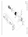
10" JOB SITE TABLE
SAW
Model:137.218240
Part list for MOTOR
I.D. No.
1502
Description
FIELDASS'Y
Size
0HX9
NEEDLE BEARING
HK-1010
1
0JAL
EXT.TOOTH LOCK WASHER
cp4
4
0JX3
HEX. SOC. SETSCREW
M5x0.8-8
2
0K3A
CR.RE. PAN HD. SCREW & WASHER
M5x0.8-30
4
0K5V
CR.-RE. COUND.HD.SCREW
M4x0.7-8
4
0KCP
CR.RE. PAN HEAD TAPPING & WASHER SCREW
M5x1 2-60
2
0KTH
STRAIN RELIEF
1
0QDZ
BEARING RETAINER
1
0QE9
MOTOR NAMEPLATE
1
0QEA
BRACKET
1
0QEC
ARBOR SHAFT ASS'Y
1
0QED
SUPPORT PLATE
1
0QM2
BRUSHHOLDER ASS'Y
2
0QQT
BRUSHASS'Y
2
0QR0
BRUSHCOVER
2
0R1Q
MOTOR HOUSING
0R1S
BEARING BUSHING
1
0R1Y
ARMATURE ASS'Y
1
0R20
BAFFLE
#6 color
#6 color
28
Qty
1
1
1
0
-I
0
0
.-I
ORIY
m
.-I
xJ
J
_D
J
OR2 %
r'-
m
J
J
J
(_C1
O(R)
<.
1502
o ]S
_o
-q
O,X['
Ok!\
OQ[}
<)<\
,/
J
J
/-
o
_D
m
L_
oo
10" JOB SITE TABLE
SAW
Model : 137.218240
Part list for STAND
I.D.
2878
Description
CLAMP HANDLE
Size
Qty
4
0lAD
WING NUT
1
01AE
LEVELING PAD
1
0J4F
FLAT WASHER
(p8X16-2.5
4
0J58
FLAT WASHER
(p5X14-1
4
0JAZ
WAVE WASHER
WW-6
2
0K7D
CR. RE. ROUND WASHER HD. SCREW
M6X1.0-10
2
0K7M
CR. RE. ROUND WASHER HD. SCREW
M6X1.0-18
1
0KKU
CR.RE. PAN HD. ROUND NECK SCREW
M5X08-10
1
0KMS
HEX. NUT
M6X1.0 T=5
1
0KQW
LOCK NUT
M5X0.8 T=5
1
0K©X
LOCK NUT
M6X1.0 T=6
4
0KQY
LOCK NUT
M8X1.25 T=8
6
213T
ROLLER WHEEL
2
22FZ
CAP HD. S©.NECK BOLT
27DJ
PAD
1
27DL
HANDLE
1
27DM
BRACKET ASS'Y (RIGHT)
1
27DV
FOOT PAD
3
27DW
DUSTCOLLECTION ELBOW
1
27DY
COUPLING
1
27DZ
BRACKET ASS'Y (LEFT)
1
27E6
HOOK
1
27RF
FOLLOWER PLATE
1
27RQ
CAP HD. SO.NECK BOLT
M8X1.25-40
4
27RR
CR.-RE. TRUSSHD. SCREW
M6X1.0-45
4
288R
HEX. HD. BOLT
M8X1.25-55
4
28BU
CAP
28BX
CR. RE. PAN HD PLAIN WASHER TAPPING SCREW
M8X1.25-45
2
1
M5X0.8-10
4
10" JOB SITE TABLE
STAND
SAW
Model : 137.218240
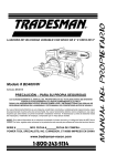
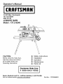
PUSH STICK CONSTRUCTION
•
•
•
•
This is a full-size drawing (actual size)
Use good quality plywood or solid wood
Use ½" or ¾" material
Push stick MUST be thinner than the
width of material being cut
/
/
//
/
/
/
;/
/
/
/
f
Notch To Prevent
Hand From
.f
Cut Here To
Push ½"
Wood
Cut Here To
Push ¾" Wood
Slipping