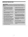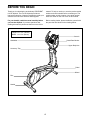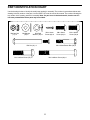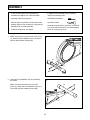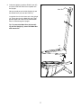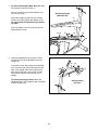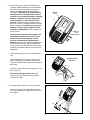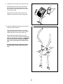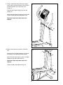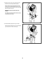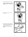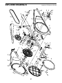
1
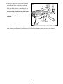
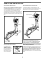
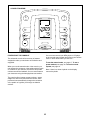
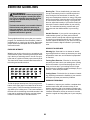
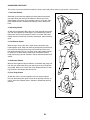
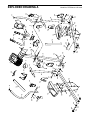
www.proform.com Model No. PFEL53911.0 Serial No. Write the serial number in the space above for reference. Serial Number Decal (under frame) QUESTIONS? If you have questions, or if parts are damaged or missing, DO NOT CONTACT THE STORE; please contact Customer Care. IMPORTANT: Please register this product (see the limited warranty on the back cover of this manual) before contacting Customer Care. CALL TOLL-FREE: 1-888-533-1333 Mon.–Fri., 6 a.m.–6 p.m. MT Sat. 8 a.m.–4 p.m. MT ON THE WEB: www.proformservice.com CAUTION Read all precautions and instructions in this manual before using this equipment. Keep this manual for future reference. USER’S MANUAL TABLE OF CONTENTS WARNING DECAL PLACEMENT . . . . . . . . . . . . . . . . . . . . . . . . . . . . . . . . . . . . . . . . . . . . . . . . . . . . . . . . . . . . . . . 2 IMPORTANT PRECAUTIONS . . . . . . . . . . . . . . . . . . . . . . . . . . . . . . . . . . . . . . . . . . . . . . . . . . . . . . . . . . . . . . . . . . 3 BEFORE YOU BEGIN. . . . . . . . . . . . . . . . . . . . . . . . . . . . . . . . . . . . . . . . . . . . . . . . . . . . . . . . . . . . . . . . . . . . . . . . 4 PART IDENTIFICATION CHART. . . . . . . . . . . . . . . . . . . . . . . . . . . . . . . . . . . . . . . . . . . . . . . . . . . . . . . . . . . . . . . . 5 ASSEMBLY . . . . . . . . . . . . . . . . . . . . . . . . . . . . . . . . . . . . . . . . . . . . . . . . . . . . . . . . . . . . . . . . . . . . . . . . . . . . . . . . 6 HOW TO USE THE ELLIPTICAL . . . . . . . . . . . . . . . . . . . . . . . . . . . . . . . . . . . . . . . . . . . . . . . . . . . . . . . . . . . . . . 15 FCC INFORMATION . . . . . . . . . . . . . . . . . . . . . . . . . . . . . . . . . . . . . . . . . . . . . . . . . . . . . . . . . . . . . . . . . . . . . . . . 19 MAINTENANCE AND TROUBLESHOOTING . . . . . . . . . . . . . . . . . . . . . . . . . . . . . . . . . . . . . . . . . . . . . . . . . . . . 20 EXERCISE GUIDELINES . . . . . . . . . . . . . . . . . . . . . . . . . . . . . . . . . . . . . . . . . . . . . . . . . . . . . . . . . . . . . . . . . . . . 22 PART LIST. . . . . . . . . . . . . . . . . . . . . . . . . . . . . . . . . . . . . . . . . . . . . . . . . . . . . . . . . . . . . . . . . . . . . . . . . . . . . . . . 25 EXPLODED DRAWING. . . . . . . . . . . . . . . . . . . . . . . . . . . . . . . . . . . . . . . . . . . . . . . . . . . . . . . . . . . . . . . . . . . . . . 26 ORDERING REPLACEMENT PARTS . . . . . . . . . . . . . . . . . . . . . . . . . . . . . . . . . . . . . . . . . . . . . . . . . . Back Cover LIMITED WARRANTY. . . . . . . . . . . . . . . . . . . . . . . . . . . . . . . . . . . . . . . . . . . . . . . . . . . . . . . . . . . . . . . Back Cover WARNING DECAL PLACEMENT This drawing shows the location(s) of the warning decal(s). If a decal is missing or illegible, see the front cover of this manual and request a free replacement decal. Apply the decal in the location shown. Note: The decal(s) may not be shown at actual size. PROFORM is a registered trademark of ICON IP, Inc. 2 IMPORTANT PRECAUTIONS WARNING: To reduce the risk of serious injury, read all important precautions and instructions in this manual and all warnings on your elliptical before using your elliptical. ICON assumes no responsibility for personal injury or property damage sustained by or through the use of this product. 1. Before beginning any exercise program, consult your physician. This is especially important for persons over age 35 or persons with pre-existing health problems. 9. The elliptical should not be used by persons weighing more than 250 lbs. (113 kg). 2. Use the elliptical only as described in this manual. 10. Wear appropriate clothes while exercising; do not wear loose clothes that could become caught on the elliptical. Always wear athletic shoes for foot protection while exercising. 3. It is the responsibility of the owner to ensure that all users of the elliptical are adequately informed of all precautions. 11. Hold the handlebars or the upper body arms when mounting, dismounting, or using the elliptical. 4. The elliptical is intended for home use only. Do not use the elliptical in a commercial, rental, or institutional setting. 12. The heart rate monitor is not a medical device. Various factors may affect the accuracy of heart rate readings. The heart rate monitor is intended only as an exercise aid in determining heart rate trends in general. 5. Keep the elliptical indoors, away from moisture and dust. Do not put the elliptical in a garage or covered patio, or near water. 13. The elliptical does not have a freewheel; the pedals will continue to move until the flywheel stops. Reduce your pedaling speed in a controlled way. 6. Place the elliptical on a level surface, with at least 3 ft. (0.9 m) of clearance in the front and rear of the elliptical and 2 ft. (0.6 m) on each side. To protect the floor or carpet from damage, place a mat under the elliptical. 14. Keep your back straight while using the elliptical; do not arch your back. 7. Inspect and properly tighten all parts regularly. Replace any worn parts immediately. 15. Over exercising may result in serious injury or death. If you feel faint or if you experience pain while exercising, stop immediately and cool down. 8. Keep children under age 12 and pets away from the elliptical at all times. 3 BEFORE YOU BEGIN Thank you for selecting the revolutionary PROFORM® 6.0 CE elliptical. The 6.0 CE elliptical provides an impressive selection of features designed to make your workouts at home more effective and enjoyable. manual. To help us assist you, note the product model number and serial number before contacting us. The model number and the location of the serial number decal are shown on the front cover of this manual. For your benefit, read this manual carefully before you use the elliptical. If you have questions after reading this manual, please see the front cover of this Before reading further, please familiarize yourself with the parts that are labeled in the drawing below. Length: 6 ft. 4 in. (193 cm) Width: 2 ft. 2 in. (66 cm) Console Handlebar Heart Rate Monitor Upper Body Arm Accessory Tray Pedal Wheel Disc Handle 4 PART IDENTIFICATION CHART Use the drawings below to identify the small parts needed for assembly. The number in parentheses below each drawing is the key number of the part, from the PART LIST near the end of this manual. The number following the key number is the quantity needed for assembly. Note: If a part is not in the hardware kit, check to see if it has been preassembled. Extra parts may be included. M8 Jam Nut (77)–4 M8 Washer (33)–2 M10 Split Washer (78)–11 M4 x 16mm Screw (92)–9 Bolt Set (31)–2 M8 x 20mm Screw (80)–2 M10 x 20mm Screw (79)–8 M8 x 45mm Button Bolt (76)–4 M10 x 45mm Screw (75)–6 M10 x 85mm Screw (82)–4 5 ASSEMBLY • To hire an authorized service technician to assemble the elliptical, call 1-800-445-2480. • In addition to the included tool(s), assembly requires the following tools: • Assembly requires two persons. one Phillips screwdriver • Place all parts in a cleared area and remove the packing materials. Do not dispose of the packing materials until you nish assembly. one rubber mallet Assembly may be easier if you have a socket set or a set of ratchet wrenches. To avoid damaging parts, do not use power tools. • To identify small parts, see page 5. 1. While a second person lifts the rear of the Frame (1), attach the Rear Stabilizer (70) to the Frame with two M10 x 85mm Screws (82). 1 70 1 82 2. Orient the Front Stabilizer (73) as indicated by the sticker. 2 73 While a second person lifts the front of the Frame (1), attach the Front Stabilizer (73) to the Frame with two M10 x 85mm Screws (82). 1 6 82 3. Orient the Upright (2) and the Shield Cover (37) as shown. Slide the Shield Cover upward onto the Upright. 3 Wire Tie Have a second person hold the Upright (2) and the Shield Cover (37) near the Frame (1). 2 Locate the wire tie in the lower end of the Upright (2). Tie the wire tie to the Main Wire (42). Then, pull the upper end of the wire tie until the Main Wire is routed through the Upright. Tip: To prevent the Main Wire (42) from falling into the Upright (2), secure the Main Wire with the wire tie. 37 Wire Tie 42 1 7 4. Tip: Avoid pinching the Main Wire (42). Slide the Upright (2) onto the Frame (1). 4 Have a second person hold the Shield Cover (37) out of the way. Avoid pinching the Main Wire (42) Attach the Upright (2) with five M10 x 20mm Screws (79) and five M10 Split Washers (78). Tip: Start all the Screws before fully tightening them. 37 Press the Shield Cover (37) into the Left and Right Shields (44, 45). 2 44, 45 79 78 78 79 1 5. Orient the Handlebar (39) as shown. Have a second person hold the Handlebar near the Upright (2). 5 39 Locate the Sensor Wires (93) in the Handlebar (39). Insert the right Sensor Wire into the right side of the Upright and insert the left Sensor Wire into the left side of the Upright. Pull the Sensor Wires upward out of the top of the Upright. 79 79 2 Tip: Avoid pinching the wires. Attach the Handlebar (39) to the Upright (2) with three M10 x 20mm Screws (79). 93 Avoid pinching the wires 8 6. The Console (4) can use four D batteries (not included); alkaline batteries are recommended. Do not use old and new batteries together or alkaline, standard, and rechargeable batteries together. IMPORTANT: If the Console has been exposed to cold temperatures, allow it to warm to room temperature before inserting batteries. Otherwise, you may damage the console displays or other electronic components. Remove the battery covers from the back of the Console, and insert batteries into the battery compartments. Make sure to orient the batteries as shown by the diagrams inside the battery compartments. Then, reattach the battery covers. 6 Battery Cover 4 Battery Cover Receptacle To purchase an optional power adapter, call the telephone number on the cover of this manual. To avoid damaging the console, use only a manufacturer-supplied power adapter. Plug one end of the power adapter into the receptacle inside the battery compartment on the console; plug the other end into an outlet installed in accordance with all local codes and ordinances. 7. Untie and discard the wire tie on the Main Wire (42). 7 4 While a second person holds the Console (4) near the Upright (2), connect the wires on the Console to the Main Wire (42) and to the Sensor Wires (93). Avoid pinching the wires 42 Insert the excess wire into the Upright (2) or into the Console (4). 2 93 Tip: Avoid pinching the wires. Attach the Console (4) to the Upright (2) with four M4 x 16mm Screws (92). 92 8. Orient the Rear Console Cover (81) as shown. 8 Have a second person hold the Rear Console Cover (81) against the Upright (2) until you complete step 9. 81 9 2 9. Orient the Front Console Cover (32) as shown. 9 32 Attach the Rear Console Cover (81) around the Upright (2) by pressing the hooks on the Rear Console Cover into the tabs on the Front Console Cover (32). 92 Attach the Front Console Cover (32) to the Upright (2) with two M4 x 16mm Screws (92). 81 2 10. Identify the Right Upper Body Arm (9), which is marked with an “R” sticker. 10 Orient the Right Upper Body Arm (9) and an Upper Body Leg (6) as shown. Insert the Right Upper Body Arm into the Upper Body Leg. Attach the Right Upper Body Arm (9) to the Upper Body Leg (6) with two M8 x 45mm Button Bolts (76) and two M8 Jam Nuts (77). Make sure that the Jam Nuts are inside the hexagonal holes. Do not fully tighten the Button Bolts yet. 8 9 Assemble the Left Upper Body Arm (8) and the other Upper Body Leg (6) in the same way. 77 Hexagonal Holes 76 77 76 6 10 6 11. Using a small plastic bag to keep your fingers clean, apply a generous amount of the included grease to the axle on the right side of the Upright (2). 11 Slide the Right Upper Body Arm (9) onto the Upright (2). Attach the Right Upper Body Arm (9) with an M8 x 20mm Screw (80) and an M8 Washer (33). Repeat this step on the other side of the elliptical. 8 2 Grease 9 33 80 12. Apply a small amount of grease to a Bolt Set (31). 12 76 Hold the end of the Right Pedal Arm (49) inside the bracket on the right Upper Body Leg (6). 76 Attach the right Upper Body Leg (6) to the Right Pedal Arm (49) with the Bolt Set (31). Repeat this step on the other side of the elliptical. Tighten the M8 x 45mm Button Bolts (76). 6 31 31 49 Grease 11 13. Identify a Pivot Cover A (19), which has hooks, and a Pivot Cover B (22), which has tabs. 13 Attach a Pivot Cover A (19) and a Pivot Cover B (22) around the Right Upper Body Arm (9) by pressing the hooks on the Pivot Cover A onto the tabs on the Pivot Cover B. Repeat this step on the other side of the elliptical. 8 Tip: Make sure that the Pivot Covers (19, 22) are positioned as shown. 19 9 22 22 19 14. Orient the Rear Upright Cover (3) as shown. 14 Attach the Rear Upright Cover (3) to the Upright (2) with three M4 x 16mm Screws (92). 2 3 92 12 92 15. Orient the Front Upright Cover (16) as shown. 15 Attach the Front Upright Cover (16) around the Upright (2) by pressing the hooks on the Front Upright Cover onto the tabs on the Rear Upright Cover (3). 16 2 3 16. Insert the Accessory Tray (5) into the Rear Upright Cover (3). 16 5 3 17. Attach a Front Leg Cover (20) and a Rear Leg Cover (21) around the right Upper Body Leg (6) by pressing the hooks on the Front Leg Cover onto the tabs on the Rear Leg Cover. 17 6 20 Repeat this step on the other side of the elliptical. 21 13 18. Identify the Right Pedal (13), which is marked with a “Right” sticker, and orient it as shown. 18 13 Attach the Right Pedal (13) to the Right Pedal Arm (49) with three M10 x 45mm Screws (75) and three M10 Split Washers (78). Make sure to use the center hole and the two outer holes to attach the Right Pedal. 49 Repeat this step on the other side of the elliptical. 78 75 19. Make sure that all parts of the elliptical are properly tightened. Note: Some hardware may be left over after assembly is completed. To protect the floor or carpet from damage, place a mat under the elliptical. 14 HOW TO USE THE ELLIPTICAL HOW TO MOVE THE ELLIPTICAL HOW TO EXERCISE ON THE ELLIPTICAL Due to the size and weight of the elliptical, moving it requires two persons. Stand in front of the elliptical, hold the upright, and place one foot against one of the front wheels. Pull on the upright and have a second person lift the handle on the rear stabilizer until the elliptical will roll on the wheels. Carefully move the elliptical to the desired location, and then lower it to the floor. To mount the elliptical, hold the handlebars or the upper body arms and step onto the pedal that is in the lowest position. Then, step onto the other pedal. Upper Body Arms Handlebars Pedals Upright Place your foot here Wheel Push the pedals until they begin to move with a continuous motion. Note: The pedal discs can turn in either direction. It is recommended that you move the pedal discs in the direction shown by the arrow; however, for variety, you can turn the pedal discs in the opposite direction. Lift here HOW TO LEVEL THE ELLIPTICAL If the elliptical rocks slightly on your floor during use, turn one or both of the leveling feet beneath the rear stabilizer until the rocking motion is eliminated. To dismount the elliptical, wait until the pedals come to a complete stop. Note: The elliptical does not have a free wheel; the pedals will continue to move until the flywheel stops. When the pedals are stationary, step off the highest pedal first. Then, step off the lowest pedal. Leveling Feet 15 CONSOLE DIAGRAM FEATURES OF THE CONSOLE You can even connect your MP3 player or CD player to the console sound system and listen to your favorite music or audio books while you exercise. The advanced console offers an array of features designed to make your workouts more effective and enjoyable. To use the manual mode, see page 17. To use a preset workout, see page 18. To use the sound system, see page 19. When you use the manual mode of the console, you can change the resistance of the pedals with the touch of a button. As you exercise, the console will provide continuous exercise feedback. You can even measure your heart rate using the handgrip heart rate monitor. Note: If there is a sheet of plastic on the display, remove the plastic. The console offers fourteen preset workouts—seven weight loss and seven performance workouts. Each preset workout automatically changes the resistance of the pedals as it guides you through an effective workout. 16 HOW TO USE THE MANUAL MODE Profile—When a workout is selected, this display mode will show a profile of the resistance settings of the workout. 1. Turn on the console. Press any button or begin pedaling to turn on the console. Pulse—This display mode will show your heart rate when you use the handgrip heart rate monitor (see step 5 on page 18). When you turn on the console, the display will turn on. A tone will sound and the console will be ready for use. Resistance (Res)—This display mode will show the resistance level of the pedals for a few seconds each time the resistance level changes. 2. Select the manual mode. Speed—This display mode will show your pedaling speed in revolutions per minute. When you turn on the console, the manual mode will be selected automatically. Time—When the manual mode is selected, this display mode will show the elapsed time. When a workout is selected, this display mode will show the time remaining in the workout. If you have selected a workout, reselect the manual mode by pressing the 7 Weight Loss Workouts button or the 7 Performance Workouts button repeatedly until a track appears in the upper display. Track—When the manual mode is selected, this display mode will show a track representing 1/4 mile (400 m). As you exercise, indicators will appear in succession around the track until the entire track appears. The track will then disappear and the indicators will again begin to appear in succession. 3. Begin pedaling and change the resistance of the pedals as desired. Press the Display Mode button repeatedly to view the desired workout information. As you pedal, change the resistance of the pedals by pressing the Resistance increase and decrease buttons. When the word SCAN appears in the display, the display will show the calories, distance, speed, and time display modes in a repeating cycle. Note: After you press the buttons, it will take a moment for the pedals to reach the selected resistance level. To reset the display to zero, press the On/Reset button. 4. Follow your progress with the display. The display can show the following workout information: Change the volume level of the console by pressing the Volume increase and decrease buttons. Calories—This display mode will show the approximate number of calories you have burned. Distance—This display mode will show the distance that you have pedaled in revolutions. 17 5. Measure your heart rate if desired. HOW TO USE A PRESET WORKOUT If there are sheets of plastic on the metal Contacts contacts on the handgrip heart rate monitor, remove the plastic. In addition, make sure that your hands are clean. To measure your heart rate, hold the handgrip heart rate monitor with your palms resting against the contacts. Avoid moving your hands or gripping the contacts tightly. 1. Turn on the console. Press any button or begin pedaling to turn on the console. When you turn on the console, the display will turn on. A tone will sound and the console will be ready for use. 2. Select a preset workout. To select a preset workout, press the 7 Weight Loss Workouts button or the 7 Performance Workouts button repeatedly until the number of the desired workout appears in the lower display. When your pulse is detected, a heart-shaped symbol will flash in the display and then your heart rate will be shown. For the most accurate heart rate reading, hold the contacts for at least 15 seconds. If your heart rate is not shown, make sure that your hands are positioned as described. Be careful not to move your hands excessively or to squeeze the contacts tightly. For optimal performance, clean the contacts using a soft cloth; never use alcohol, abrasives, or chemicals to clean the contacts. Profile When you select a preset workout, a profile of the resistance levels of the workout will scroll across the upper display, the duration of the workout will appear in the center display, and the number of the workout will appear in the lower display. 6. Turn on the fan if desired. The fan has high and low speed settings. Press the Fan increase and decrease buttons repeatedly to select a fan speed or to turn off the fan. 3. Begin pedaling to start the workout. Each workout is divided into several one-minute segments. One resistance level is programmed for each segment. Note: The same resistance level may be programmed for consecutive segments. Note: If the pedals do not move for about thirty seconds, the fan will turn off automatically. During the workout, the workout profile will show your progress (see the drawing above). The flashing segment of the profile represents the current segment of the workout. The height of the flashing segment indicates the resistance level for the current segment. 7. When you are finished exercising, the console will turn off automatically. If the pedals do not move for several seconds, a series of tones will sound, the console will pause, and the time will flash in the display. At the end of each segment of the workout, a series of tones will sound and the next segment of the profile will begin to flash. If a different resistance level is programmed for the next segment, the resistance level will appear in the display for a few seconds to alert you. The resistance of the pedals will then change. If the pedals do not move for several minutes, the console will turn off and the display will be reset. 18 If the resistance level for the current segment is too high or too low, you can manually override the setting by pressing the Resistance buttons. However, when the current segment ends, the pedals will automatically adjust to the resistance level for the next segment. 6. Turn on the fan if desired. If you stop pedaling for several seconds, a series of tones will sound and the workout will pause. See step 7 on page 18. See step 6 on page 18. 7. When you are finished exercising, the console will turn off automatically. To resume the workout, simply resume pedaling. The workout will continue until the last segment of the profile flashes and the last segment of the workout ends. HOW TO USE THE SOUND SYSTEM To play music or audio books through the console sound system while you exercise, plug the included audio cable into the jack on the console and into a jack on your MP3 player or CD player; make sure that the audio cable is fully plugged in. 4. Follow your progress with the display. See step 4 on page 17. Next, press the play button on your MP3 player or CD player. Adjust the volume level using the Volume increase and decrease buttons on the console or the volume control on your MP3 player or CD player. 5. Measure your heart rate if desired. See step 5 on page 18. FCC INFORMATION This equipment has been tested and found to comply with the limits for a Class B digital device, pursuant to part 15 of the FCC Rules. These limits are designed to provide reasonable protection against harmful interference in a residential installation. This equipment generates, uses, and can radiate radio frequency energy and, if not installed and used in accordance with the instructions, may cause harmful interference to radio communications. However, there is no guarantee that interference will not occur in a particular installation. If this equipment does cause harmful interference to radio or television reception, which can be determined by turning the equipment off and on, the user is encouraged to try to correct the interference by one or more of the following measures: • • • • Reorient or relocate the receiving antenna. Increase the separation between the equipment and the receiver. Connect the equipment into an outlet on a circuit different from that to which the receiver is connected. Consult the dealer or an experienced radio/TV technician for help. WARNING: Per FCC rules, changes or modifications not expressly approved by ICON could void the user’s authority to operate the equipment. 19 MAINTENANCE AND TROUBLESHOOTING Inspect and tighten all parts of the elliptical regularly. Replace any worn parts immediately. Note: For clarity, the pedal disc is shown removed in the drawing below. To clean the elliptical, use a damp cloth and a small amount of mild soap. IMPORTANT: To avoid damage to the console, keep liquids away from the console and keep the console out of direct sunlight. Next, locate the Reed Switch (58). Loosen, but do not remove, the M4 x 16mm Screw (92). CONSOLE TROUBLESHOOTING 86 If the console display becomes dim, replace all the batteries at the same time; most console problems are the result of low batteries. See assembly step 6 on page 9 for replacement instructions. 92 41 If the console does not display your heart rate when you use the handgrip heart rate monitor, see step 5 on page 18. 58 HOW TO ADJUST THE REED SWITCH If the console does not display correct feedback, the reed switch should be adjusted. To adjust the reed switch, you must first remove the Shield Cover (37). Using a flat screwdriver, release the tabs along the sides of the Shield Cover and then remove the Shield Cover. 37 Next, rotate the Pulley (86) until a Magnet (41) is aligned with the Reed Switch (58). Slide the Reed Switch slightly toward or away from the Magnet. Then, retighten the M4 x 16mm Screw (92). Rotate the Pulley (86) for a moment. Repeat these actions until the console displays correct feedback. When the reed switch is correctly adjusted, reattach the shield cover. 20 HOW TO ADJUST THE DRIVE BELT Loosen the Pivot Screw (88). Then, tighten the Drive Belt Adjustment Screw (72) until the Drive Belt (46) is tight. If you can feel the pedals slip while you are pedaling, even when the resistance is adjusted to the highest level, the drive belt may need to be adjusted. To adjust the drive belt, you must remove the shield cover and the left shield (see the instructions below). 46 See EXPLODED DRAWING B on page 27. Using a flat screwdriver, release the tabs along the sides of the Shield Cover (37), and then remove the Shield Cover. Next, remove the M4 x 16mm Screws (92) and the M4 x 12mm Self-tapping Screws (97) from the Left and Right Shields (44, 45). Make sure to note which size of Screw you remove from each hole. Then, gently remove the Left Shield. 88 72 When the Drive Belt (46) is tight, tighten the Pivot Screw (88). Then, reattach the left shield and the shield cover. 21 EXERCISE GUIDELINES Burning Fat—To burn fat effectively, you must exercise at a low intensity level for a sustained period of time. During the first few minutes of exercise, your body uses carbohydrate calories for energy. Only after the first few minutes of exercise does your body begin to use stored fat calories for energy. If your goal is to burn fat, adjust the intensity of your exercise until your heart rate is near the lowest number in your training zone. For maximum fat burning, exercise with your heart rate near the middle number in your training zone. WARNING: Before beginning this or any exercise program, consult your physician. This is especially important for persons over age 35 or persons with pre-existing health problems. The heart rate monitor is not a medical device. Various factors may affect the accuracy of heart rate readings. The heart rate monitor is intended only as an exercise aid in determining heart rate trends in general. Aerobic Exercise—If your goal is to strengthen your cardiovascular system, you must perform aerobic exercise, which is activity that requires large amounts of oxygen for prolonged periods of time. For aerobic exercise, adjust the intensity of your exercise until your heart rate is near the highest number in your training zone. These guidelines will help you to plan your exercise program. For detailed exercise information, obtain a reputable book or consult your physician. Remember, proper nutrition and adequate rest are essential for successful results. WORKOUT GUIDELINES EXERCISE INTENSITY Warming Up—Start with 5 to 10 minutes of stretching and light exercise. A warm-up increases your body temperature, heart rate, and circulation in preparation for exercise. Whether your goal is to burn fat or to strengthen your cardiovascular system, exercising at the proper intensity is the key to achieving results. You can use your heart rate as a guide to find the proper intensity level. The chart below shows recommended heart rates for fat burning and aerobic exercise. Training Zone Exercise—Exercise for 20 to 30 minutes with your heart rate in your training zone. (During the first few weeks of your exercise program, do not keep your heart rate in your training zone for longer than 20 minutes.) Breathe regularly and deeply as you exercise—never hold your breath. Cooling Down—Finish with 5 to 10 minutes of stretching. Stretching increases the flexibility of your muscles and helps to prevent post-exercise problems. EXERCISE FREQUENCY To find the proper intensity level, find your age at the bottom of the chart (ages are rounded off to the nearest ten years). The three numbers listed above your age define your “training zone.” The lowest number is the heart rate for fat burning, the middle number is the heart rate for maximum fat burning, and the highest number is the heart rate for aerobic exercise. To maintain or improve your condition, complete three workouts each week, with at least one day of rest between workouts. After a few months of regular exercise, you may complete up to five workouts each week, if desired. Remember, the key to success is to make exercise a regular and enjoyable part of your everyday life. 22 SUGGESTED STRETCHES The correct form for several basic stretches is shown at the right. Move slowly as you stretch—never bounce. 1. Toe Touch Stretch Stand with your knees bent slightly and slowly bend forward from your hips. Allow your back and shoulders to relax as you reach down toward your toes as far as possible. Hold for 15 counts, then relax. Repeat 3 times. Stretches: Hamstrings, back of knees and back. 1 2. Hamstring Stretch 2 Sit with one leg extended. Bring the sole of the opposite foot toward you and rest it against the inner thigh of your extended leg. Reach toward your toes as far as possible. Hold for 15 counts, then relax. Repeat 3 times for each leg. Stretches: Hamstrings, lower back and groin. 3. Calf/Achilles Stretch With one leg in front of the other, reach forward and place your hands against a wall. Keep your back leg straight and your back foot flat on the floor. Bend your front leg, lean forward and move your hips toward the wall. Hold for 15 counts, then relax. Repeat 3 times for each leg. To cause further stretching of the achilles tendons, bend your back leg as well. Stretches: Calves, achilles tendons and ankles. 3 4 4. Quadriceps Stretch With one hand against a wall for balance, reach back and grasp one foot with your other hand. Bring your heel as close to your buttocks as possible. Hold for 15 counts, then relax. Repeat 3 times for each leg. Stretches: Quadriceps and hip muscles. 5. Inner Thigh Stretch Sit with the soles of your feet together and your knees outward. Pull your feet toward your groin area as far as possible. Hold for 15 counts, then relax. Repeat 3 times. Stretches: Quadriceps and hip muscles. 23 5 NOTES 24 PART LIST Key No. Qty. 1 2 3 4 5 6 7 8 9 10 11 12 13 14 15 16 17 18 19 20 21 22 23 24 25 26 27 28 29 30 31 32 33 34 35 36 37 38 39 40 41 42 43 44 45 46 47 48 49 50 1 1 1 1 1 2 1 1 1 2 2 1 1 1 2 1 4 10 2 2 2 2 4 1 1 2 1 2 4 2 2 1 4 1 1 1 1 2 1 2 2 1 2 1 1 1 2 2 1 2 Model No. PFEL53911.0 R0112A Description Key No. Qty. Frame Upright Rear Upright Cover Console Accessory Tray Upper Body Leg Resistance Wheel Left Upper Body Arm Right Upper Body Arm Foam Grip Upper Body Arm Cap Left Pedal Right Pedal Left Pedal Arm Pedal Bracket Front Upright Cover Pivot Bushing Pedal Disc Mount Pivot Cover A Front Leg Cover Rear Leg Cover Pivot Cover B Pedal Arm Bushing Crank Right Crank Arm Pedal Disc Crank Arm Spacer Wire Bearing Pedal Arm Cap Bolt Set Front Console Cover M8 Washer Adjustment Block M5 Washer Small Snap Ring Shield Cover Crank Bearing Handlebar Large Snap Ring Magnet Main Wire M6 Washer Left Shield Right Shield Drive Belt Leveling Foot Stabilizer Cap Right Pedal Arm Wheel 51 52 53 54 55 56 57 58 59 60 61 62 63 64 65 66 67 68 69 70 71 72 73 74 75 76 77 78 79 80 81 82 83 84 85 86 87 88 89 90 91 92 93 94 95 96 97 * * * 1 1 1 1 1 1 1 1 4 1 1 1 2 1 1 1 1 1 4 1 2 1 1 1 6 4 6 11 8 2 1 4 1 10 2 1 1 1 4 1 2 20 2 1 1 1 2 – – – Description Flywheel Idler C-magnet Resistance Motor Motor Bracket Adjustment Arm Reed Switch Clamp Reed Switch/Wire M8 x 10mm Screw Key M8 Locknut M6 x 16mm Screw Shoulder Screw Flywheel Axle C-magnet Bolt Idler Bolt Key Screw Crank Arm Bolt Resistance Motor Bolt Rear Stabilizer Motor Bracket Screw Drive Belt Adjustment Screw Front Stabilizer M6 Locknut M10 x 45mm Screw M8 x 45mm Button Bolt M8 Jam Nut M10 Split Washer M10 x 20mm Screw M8 x 20mm Screw Rear Console Cover M10 x 85mm Screw M5 x 7mm Screw #10 x 13mm Screw M8 x 18mm Screw Pulley M3.5 x 12mm Screw Pivot Screw M8 x 15mm Screw M4 x 16mm Ground Screw Adjustment Nut M4 x 16mm Screw Sensor/Wire Flywheel Bearing Audio Cable Left Crank Arm M4 x 12mm Self-tapping Screw User’s Manual Assembly Tool Grease Packet Note: Specifications are subject to change without notice. For information about ordering replacement parts, see the back cover of this manual. *These parts are not illustrated. 25 30 85 33 29 22 80 33 26 29 14 78 84 12 15 17 8 84 75 17 10 11 21 19 78 23 31 76 6 81 23 95 79 31 92 78 79 3 77 78 20 4 5 78 29 79 79 2 29 92 92 33 85 16 78 30 10 21 19 28 75 13 15 84 39 79 93 31 49 84 17 78 76 79 32 17 23 9 92 23 6 80 31 20 77 33 22 11 EXPLODED DRAWING A Model No. PFEL53911.0 R0112A 92 18 97 18 44 59 18 92 27 18 26 92 96 92 26 47 48 24 82 27 92 70 86 41 47 89 38 40 89 41 35 56 92 34 57 90 72 58 92 48 66 88 43 91 77 71 55 83 87 7 42 38 52 36 40 53 65 77 74 54 94 51 64 1 69 63 97 92 50 37 25 45 73 92 46 67 63 62 60 68 92 50 61 43 82 EXPLODED DRAWING B Model No. PFEL53911.0 R0112A ORDERING REPLACEMENT PARTS To order replacement parts, please see the front cover of this manual. To help us assist you, be prepared to provide the following information when contacting us: • the model number and serial number of the product (see the front cover of this manual) • the name of the product (see the front cover of this manual) • the key number and description of the replacement part(s) (see the PART LIST and the EXPLODED DRAWING near the end of this manual) LIMITED WARRANTY IMPORTANT: You must register this product within 30 days of the purchase date to avoid added fees for service needed under warranty. Go to www.proformservice.com/registration. ICON Health & Fitness, Inc. (ICON) warrants this product to be free from defects in workmanship and material, under normal use and service conditions. The frame is warranted for five (5) years from the date of purchase. Parts and labor are warranted for ninety (90) days from the date of purchase. This warranty extends only to the original purchaser (customer). ICON’s obligation under this warranty is limited to repairing or replacing, at ICON’s option, the product through one of its authorized service centers. All repairs for which warranty claims are made must be preauthorized by ICON. If the product is shipped to a service center, freight charges to and from the service center will be the customer’s responsibility. If replacement parts are shipped while the product is under warranty, the customer will be responsible for a minimal handling charge. For in-home service, the customer will be responsible for a minimal trip charge. This warranty does not extend to freight damage to the product. This warranty will automatically be voided if the product is used as a store display model, if the product is purchased or transported outside the USA, if all instructions in this manual are not followed, if the product is abused or improperly or abnormally used, or if the product is used for commercial or rental purposes. No other warranty beyond that specically set forth above is authorized by ICON. ICON is not responsible or liable for indirect, special, or consequential damages arising out of or in connection with the use or performance of the product; damages with respect to any economic loss, loss of property, loss of revenues or prots, loss of enjoyment or use, or costs of removal or installation; or other consequential damages of any kind. Some states do not allow the exclusion or limitation of incidental or consequential damages. Accordingly, the above limitation may not apply to the customer. The warranty extended hereunder is in lieu of any and all other warranties, and any implied warranties of merchantability or tness for a particular purpose are limited in their scope and duration to the terms set forth herein. Some states do not allow limitations on how long an implied warranty lasts. Accordingly, the above limitation may not apply to the customer. This warranty provides specic legal rights; the customer may have other rights that vary from state to state. ICON Health & Fitness, Inc., 1500 S. 1000 W., Logan, UT 84321-9813 Part No. 317409 R0112A Printed in China © 2011 ICON IP, Inc.