1
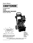
Owner's Manual
CRRFTSMRN°
6.0 HORSEPOWER
2,400 PSI
2.2 GPM
HIGH PRESSUR
WASHER
Model No. 580.768330
HOURS:
Mon.-
CAUTION"
Fri. 8 a.m. to 5 p.m. (CT)
Before
using this product,
read this manual and follow all Safety
Rules and Operating Instructions.
SEARS,
ROEBUCK
and CO.,
Hoffman
Estates,
IL 60179
Visit our Craftsman website: www.sears.com/craftsman
Part No. B5658
Draft
1 (6/28/2000)
•
•
•
•
•
Safety
Assembly
Operation
Maintenance
Parts
•
Espafiol
U.S.A.
WARRANTY ...................................
2
STORAGE ...................................
13
SAFETY RULES ..............................
2-3
TROUBLESHOOTING
ASSEMBLY ..................................
4-5
REPLACEMENT
6-9
EMISSION CONTROL WARRANTY
OPERATION .................................
MAINTENANCE
.............................
SPECIFICATIONS
9-12
.............................
LIMITED
10
WARRANTY
..........................
14
PARTS ......................
16-23
................
24
ESPANOL .................................
25-39
HOW TO ORDER PARTS ...............
ON CRAFTSMAN
HIGH PRESSURE
BACK PAGE
WASHER
For one year from the date of purchase, when this Craftsman pressure washer is maintained and operated
according to the instructions in the owner's manual, Sears will repair, free of charge, any defect in material and
workmanship.
If this washer is used for commercial purposes, this warranty applies for only 90 days from the date of
purchase. If this high pressure washer is used for rental purposes, this warranty applies for only 30 days after
date of purchase.
This warranty does not cover:
• Expendable items such as spark plugs or air filters, which become worn during normal use.
• Repairs necessary because of operator abuse or negligence, including damage resulting from no water
being supplied to pump or failure to maintain the equipment according to the instructions contained in the
owner's manual.
Warranty service is available by returning the high pressure washer to the nearest Sears service center or
dealer in the United States.
This warranty gives you specific legal rights and you may also have other rights, which vary from state to state.
Sears, Roebuck
and Co., Dept. 817WA,
,_
The engine exhaust from this product
contains chemicals known to the State of
California to cause cancer, birth defects, or
other reproductive
harm.
,_
,_
CAUTION!or making
When setting
adjusting
repairs up,
to transporting,
your high
pressure washer, always disconnect the spark
plug wire from the spark plug and place the wire
where it cannot contact spark plug.
DANGER!
Engine
exhaust gas.
gases
contain
DEADLY carbon
monoxide
This
dangerous
gas, if breathed in sufficient concentrations, can
cause unconsciousness or even death. Operate
this equipment only in the open air where
adequate ventilation is available.
Hoffman
Estates,
IL 60179
DANGER!
Gasoline
is highly FLAMMABLE
and its vapors
are EXPLOSIVE.
Do Not permit
smoking, open flames, sparks or heat in the
vicinity while handling gasoline. Avoid spilling
gasoline on a hot engine. Allow unit to cool
before refueling. Comply with all laws regulating
storage and handling of gasoline.
Read this manual carefully and become familiar
with your pressure washer. Know its applications,
its limitations, and any hazards involved.
•
Locate this pressure washer in areas away from
combustible materials, combustible fumes or dust.
•
The high pressure equipment is designed to be
used with Sears authorized parts ONLY. If you use
this equipment with parts that do not comply with
minimum specifications, the user assumes all risks
and liabilities.
•
Some chemicals or detergents may be harmful if
inhaled or ingested, causing severe nausea,
fainting or poisoning. The harmful elements may
cause property damage or severe injury.
• Do NotallowCHILDREN
tooperatethe pressure
washerat anytime.
• Operateengineonlyatgovernedspeed.Running
theengineatexcessivespeedsincreases
the
hazardof personalinjury.DoNottamperwithparts
whichmayincreaseor decreasethe governed
speed.
• Do Notwearlooseclothing,jewelryor anything
thatmaybecaughtin thestarteror otherrotating
parts.
• Beforestartingthe pressurewasherincold
weather,checkall partsoftheequipment
andbe
sureicehasnotformedthere.
• Neverusea spraygunwhichdoesnothavea
triggerlockor triggerguardin placeandinworking
order.
• Keepthe hoseconnected
to machineorthe spray
gunwhilethe systemis pressurized.
Disconnecting
thehosewhilethe unitis pressurized
is dangerous.
• Unitswithbrokenor missingparts,or without
protective
housingor covers,shouldNEVERbe
operated.
• Checkthefuelsystemforleaksor signsof
deterioration,
suchaschafedor spongyhose,
looseor missingclamps,or damagedtankor cap.
Correctalldefectsbeforeoperating
the pressure
washer.
• Do Notsprayflammableliquids.
• Usea respiratoror maskwheneverthereis a
chancethatvaporsmaybeinhaled.Readall
instructions
withmasksoyouarecertainthe mask
willprovidethe necessaryprotection
against
inhalingharmfulvapors.
• Neveraimthespraygunat people,animalsor
plants.Thehighpressurestreamofwaterthatthis
equipment
producescanpierceskinandits
underlying
tissues,leadingto seriousinjuryand
possibleamputation.
• Neverallowanypartofthe bodytocomein
contactwiththefluidstream.Do Notcomein
contactwitha fluidstreamcreatedby a leakinthe
highpressurehose.
• Alwaysweareyeprotection
whenyouusethis
equipment
orwhenyouareinthevicinitywhere
theequipment
is in use.
• Highpressurespraycancausepaintchipsor other
particlesto becomeairborne.
• Do Notoperatethepressurewasherabovethe
ratedpressure.
,_
• Nevermovethemachineby pullingonthe high
pressurehose.Usethehandleprovidedonthe
unit.
• Alwaysbecertainthe spraygun,nozzlesand
accessories
arecorrectlyattached.
• DoNot securethe sprayguninthe (open)
position.
• Highpressurespraymaydamagefragileitems
includingglass.DoNot pointspraygunat glass
wheninthejet spraymode.
• Holdthespraygunfirmlyinyourhandbeforeyou
starttheunit.Failureto doso couldresultinan
injuryfroma whippingspraygun.Do Notleavethe
spraygununattended
whilethe machineis
running.
• Thecleaningareashouldhaveadequateslopes
anddrainageto reducethe possibility
ofa fall due
to slipperysurfaces.
• Keepwatersprayawayfromelectricwiringor fatal
electricshockmayresult.
• DoNot by-passanysafetydeviceonthis
machine.
• Themufflerandengineheatupduringoperation
andremainhotimmediately
aftershuttingitdown.
Avoidcontactwitha hot muffleror engineasyou
couldbeseverelyburned.
• Operateandstorethis unitona stablesurface.
• Highpressurehosecandevelopleaksfromwear,
kinking,abuse,etc.Watersprayingfroma leakis
capableof injectingmaterialintoskin.Inspecthose
eachtimebeforeusingit. Checkallhosesforcuts,
leaks,abrasions
or bulgingof cover,or damageor
movement
of couplings.Ifanyof theseconditions
exist,replacehoseimmediately.
Neverrepairhigh
pressurehose.Replaceitwithanotherhosethat
exceedsmaximumpressureratingof yourunit.
• Themufflerandaircleanermustbe installedandin
goodconditionbeforeoperatingthe pressure
washer.Thesecomponents
actas sparkarresters
ifthe enginebackfires.
Inthe Stateof Californiaa sparkarresteris required
bylaw(Section4442ofthe CaliforniaPublic
Resources
Code).Otherstatesmayhavesimilarlaws.
Federallawsapplyonfederallands.
NOTE:Ifyouequipthe mufflerwitha sparkarrester,it
mustbemaintained
in effectiveworkingorder.You
canordera sparkarresterthroughyourauthorized
Searsservicecenter.
THIS
IS THE INJURY
SAFETY HAZARDS.
ALERT SYMBOL.
IT ISSAFETY
USED TO
ALERT YOU
TO POTENTIAL
PERSONAL
OBEY ALL
MESSAGES
THAT
FOLLOW THIS
SYMBOL TO AVOID POSSIBLE INJURY OR DEATH.
Your pressure washer requires some assembly and is
ready for use only after it has been properly serviced
with the recommended oil and fuel.
If you have any problems with the assembly of
your pressure washer, please call the pressure
washer helpline at 1-800-222-3136.
IMPORTANT: Any attempt to run the engine before it
has been serviced with the recommended oil will result
in an engine failure.
REMOVE PRESSURE
FROM CARTON
WASHER
Become familiar with each piece before assembling
the pressure washer. Check all contents against the
illustration on page 6. If any parts are missing or
damaged, call the pressure washer helpline at
1-800-222-3136.
ASSEMBLING
WASHER
YOUR PRESSURE
Your Craftsman high pressure washer was mostly
assembled at the factory. However, you will need to
perform these tasks before you can operate your
pressure washer:
•
Remove parts box shipped with your pressure
washer.
•
•
Add oil to engine crankcase.
Add fuel to fuel tank.
•
Slice two corners opposite guide handle end of
carton from top to bottom so the panel can be
folded down flat.
•
Connect pressure hose to spray gun and pump.
•
Connect water supply to the pump.
Roll the pressure washer out the open end of the
carton.
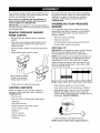
Add Engine
•
•
Raise guide handle, secure in place.
Oil
IMPORTANT: Any attempt to crank or start the engine
before it has been properly serviced with the
recommended oil may result in an engine failure.
NOTE: When adding oil to the engine crankcase, use
only high quality detergent oil rated with API service
classification SF, SG, or SH rated SAE 30 weight.
/
Other viscosity oils shown in the chart may be used
when the average temperature in your area is within
the recommended range.
Lift the handle to upright
position and slide the
locking caps into place
oF
oc
•
Check carton for additional loose parts.
CARTON
Place pressure washer on a level surface.
CONTENTS
Clean area around oil fill and remove oil dipstick.
Wipe dipstick clean. Pour oil into oil fill opening.
Replace and tighten dipstick, remove and and
check oil level. Oil level should be at "Full" mark on
the dipstick. DO NOT OVERFILL.
Check all contents. If any parts are missing or
damaged, call the pressure washer helpline at
1-800-222-3136.
•
The main unit
•
Parts box (which includes items listed below)
Spray gun
High pressure hose
Nozzle extension with quick connect
Quick connect nozzles
Engine oil
Owner's manual
Nozzle cleaning kit
O-Ring kit
•
Install oil dipstick, hand tighten securely.
NOTE: Check oil often during engine break-in.
Add Gasoline
_
DANGER!
Neverengine
fill fuel istank
indoors.
Never
fill fuel tank when
running
or hot.
Do
Not smoke when filling fuel tank.
_
ARNING!
fill expansion.
fuel tank completely
Provide
spaceNever
for fuel
Wipe awayfull.
any fuel spillage from engine and equipment
before starting.
•
Use fresh, clean unleaded automotive gasoline and
store in approved, clean, covered containers. Use
clean fill funnels. Never use "stale" gasoline left
over from last season or gasoline stored for long
periods.
•
Clean area around fuel fill cap, remove cap.
•
Slowly add "UNLEADED" regular gasoline to fuel
tank. Use a funnel to prevent spillage. Fill tank to
about 1/2" below the bottom of the filler neck.
1/2" Air Space
•
Before you connect your garden hose to the water
inlet, inspect the inlet screen. Clean the screen if it
contains debris or have it replaced if damaged. Do
Not run the pressure washer if the inlet screen
is damaged.
•
Connect garden hose to water inlet. Tighten by
hand.
. Tank
Fuel
_
•
Hose and Water
Supply
to Pump
IMPORTANT: You must assemble nozzle extension
and attach all hoses before you start engine. Starting
engine without all hoses connected and water
supplied will damage pump.
•
convenience-type water shut-off valve. Damage
to pressure washer resulting from disregarding
this warning will not be covered by the warranty.
Install fuel cap and wipe up any spilled gasoline.
Connect
Uncoil high pressure hose and attach one end of
hose to the base of the spray gun. Tighten by
hand.
ARNING! garden
There MUST
be at least
feet of
unrestricted
hose between
the ten
pressure
washer inlet and any flow shut off device, such
as a 'Y' shut-off connector or other
•
_
Turn ON the water (open valve completely).
AUTION!
Before
the pressure
washer,
be sure
you starting
are wearing
adequate
eye protection.
CHECKLIST
ENGINE
BEFORE STARTING
Review the assembly to ensure you have performed
all of the following:
Attach other end of high pressure hose to the high
pressure outlet on the pump. Tighten by hand.
•
Check that oil has been added to proper level in
engine crankcase before trying to start the
pressure washer.
•
Add proper gasoline to fuel tank.
•
Check for properly tightened hose connections
(high pressure and water supply) and for tight
connections and that there are no kinks, cuts, or
damage to the high pressure hose.
•
Provide proper water supply (not to exceed 140°F).
•
Be sure to read "Safety Rules" and "Operation"
sections before using the pressure washer.
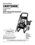
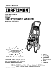
KNOW YOUR PRESSURE
WASHER
Read the owner's manual and safety rules before operating your pressure washer.
Compare the illustrations with your pressure washer to familiarize yourself with the locations of various controls
and adjustments. Save this manual for future reference.
Spray Nozzles
Spray Gun
High Pressure Hose
Oil Fill Cap
Recoil Starter
Gas Cap
Air Filter
Choke Knob
Throttle Control Lever
Detergent Pick-Up
Tube and Filter
Nozzle Extension
with Quick Connect
Water Inlet
High Pressure Outlet
Pump
Air Filter - Dry type filter element limits the amount of
dirt and dust that gets in the engine.
Oil Fill Cap - Fill engine with oil here. See page 4 for
oil recommendations.
Choke Knob - Used to help start a cold engine.
Pump - Develops high pressure water.
Detergent Pick-Up Tube and Filter - Use to draw
detergent from chemical bottle to the low pressure
water stream.
Recoil Startermanually.
Used for starting the engine
Gas Cap - Fill engine with regular unleaded gasoline
here.
Spray Gun - Controls the application of water onto
cleaning surface with trigger device. Includes safety
latch.
High Pressure Hose - Connect one end to the spray
gun and other end to the high pressure outlet.
Spray Nozzles - Chemical injection, 0 °, 15 °, 40°: for
various cleaning applications.
High Pressure
hose.
Throttle Control Lever - Sets engine in starting
mode for recoil starter and stops running engine.
Outlet - Connection for high pressure
Nozzle Extension with Quick Connect - Allows you
to switch between four different spray nozzles.
Water Inlet - Connection for garden hose.
HOW TO USE YOUR PRESSURE
WASHER
Safety Goggles
If you have any problems operating your pressure
washer, please call the pressure washer helpline at
1-800-222-3136.
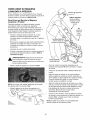
To Start Your Pressure
Left Hand
squeezes trigger
and steadies
Washer
To start your engine-powered pressure washer for the
first time, follow these instructions step-by-step. This
starting information also applies whenever you start
the engine after you have let the pressure washer sit
idle for at least a day.
•
•
Make sure unit is in a level position.
•
Connect the garden hose to the water inlet on the
pressure washer pump. Turn ON the water.
•
Do Not
attach
nozzle
extension
Place the pressure washer in an area close
enough to an outside water source capable of
supplying water at a flow rate greater than
2.2 gallons per minute.
Check that the high pressure hose is tightly
connected to the spray gun and to the pump. See
"Assembling Your Pressure Washer" for
illustrations.
•
A
upper part of unit
\
AUTION:
Not run and
the pump
water
supply Do
connected
turned without
on. Youthe
must follow this caution or the pump will be
damaged.
Left
holds base
Rotate the choke knob to the "Choke" position.
•
Place your left foot on the unit's lower frame.
•
Grasp the spray gun with your left hand and
squeeze the trigger on the spray gun. Water will
flow out of the spray gun in a thin stream. Continue
to squeeze the trigger. Your left hand will also
serve to steady the unit.
•
Grasp the recoil starter handle with your right hand,
as shown. Pull the starter handle lightly until you
feel some resistance, then pull briskly. Return the
starter grip handle slowly. Do Not let rope "snap
back" against starter.
•
When engine starts, release the spray gun trigger
and slowly rotate choke knob to the "Run" position
as engine warms and runs smoothly.
•
Engage the safety latch to the spray gun trigger.
NOTE: For a warm engine, be sure the choke knob is
in the "Run" position.
Move the throttle lever to "Fast" position, shown on
unit as a rabbit.
l
Right Hand
pulls recoil
starter handle
Safety Latch
•
As shown at the right, ensure the nozzle extension
is NOT attached to the spray gun.
• Attachthe nozzleextensionandtightenby hand.
Cleaning
,_
• Choosethe nozzleyouwantto useandinsertit
intothe nozzleextension.See"Howto Usethe
Nozzles"below.
How to Stop Your Pressure
Washer
and Applying
Chemical
WARNING!
You must
attach the
all engine
hoses before
you start the engine.
Starting
without
all the hoses connected and without the water
turned ON will damage the pump.
IMPORTANT: Use soaps designed specifically for
pressure washers. Household detergents could
damage the pump.
To apply detergent follow these steps:
• Review the use of the nozzles.
•
Prepare the detergent solution as required by the
manufacturer.
Squeeze trigger on the spray gun to relieve
pressure in the hose.
•
Hang the detergent solution container on the hook
at the rear of the pressure washer.
NOTE: A small amount of water will squirt out when
you release the pressure.
•
Place the small filter of the chemical injection tube
into the detergent container.
•
Move throttle lever on engine to "Stop" position.
•
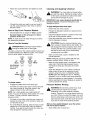
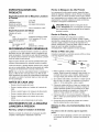
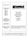
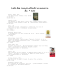
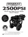
How to Use the Nozzles
_
,_
DANGER!
locking
the Never
safety exchange
latch on thenozzles
trigger. without
The quick-connect on the nozzle extension allows you
to switch between four different nozzles. The nozzles
vary the spray pattern as shown here.
•
AUTION!
the chemical
injection
tube
from
coming Keep
in contact
with the hot
muffler.
This
will damage the chemical injection tube. When
inserting the filter into a chemical bottle, route
the tube so as to keep it from inadvertently
contacting the hot muffler.
Make sure the black nozzle is installed on the
nozzle extension.
NOTE: Detergent cannot be applied with the high
pressure nozzles (White, Yellow, or Red).
Black
25°
Low Pressure
Use to apply
chemical
White
400
15 °
0o
Yellow
Red
•
Make sure the garden hose is connected to the
water inlet. Check that high pressure hose is
connected to spray gun and pump, then start
engine.
•
Apply the detergent to a dry surface, starting at
lower portion of area to be washed and work
upward, using long, even, overlapping strokes.
Do Not allow the detergent to dry on. Allowing
detergent to dry on surface may cause streaking.
•
Allow the detergent to soak between 3-5 minutes
before washing and rinsing. Reapply as needed to
prevent surface from drying.
To change nozzles:
•
Engage the safety latch on the spray gun.
Pressure
•
Pull back the collar on the quick-connect and pull
the current nozzle off. Store the nozzle in the
space provided on the control panel.
_
NOTE: For a more gentle rinse, select white 40 °
nozzle. To scour the surface, select yellow 15 ° or red
0 ° nozzle. To apply chemical, select black low
pressure nozzle.
•
Pull back on the collar, insert the new nozzle and
release the collar. Pull on the nozzle to make sure
it is securely in place.
•
For most effective cleaning, keep the spray nozzle
between 8 to 24 inches away from the cleaning
surface. If you get the spray nozzle too close, you
may damage the cleaning surface.
Washer
Rinsing
ARNING!
Be extremely
careful
if you must
use
the pressure
washer from
a ladder,
scaffolding or any other relatively unstable
location. Pressure in a running washer builds as
you climb. When you press the trigger, the recoil
from the initial spray could cause you to fall. The
high pressure spray could also cause you to fall
if you are too close to the cleaning surface.
After you have applied detergent, scour the surface
and rinse it clean as follows:
•
Apply safety latch to spray gun.
• Removethe blackchemicalnozzlefromthe nozzle Automatic Cool Down System
extension.
(Thermal Relief)
• Selectandinstallthedesiredhighpressurenozzle If you run the engine on your pressure washer for
followingtheinstructions
"Howto Usethe Nozzles". 3-5 minutes without pressing the trigger on the spray
gun, circulating water in the pump can reach a
• Keepthe sprayguna safedistancefromthe area
temperature between 140-145°F. When the water
youplanto spray.
reaches this temperature, the automatic cool down
• Applya highpressurespraytoan smallareaand
system engages and cools the pump by discharging
thencheckthe surfacefordamage.If nodamage
the warm water onto the ground. This system prevents
is found,youcanassumeit is okaytocontinue
internal damage to the pump. Once the pump has
cleaning.
cooled, it will stop discharging.
• Startatthetop oftheareato berinsed,working
NOTE: This is not a leak. Do Not return the pressure
downwithsameoverlapping
strokesusedfor
washer to the store.
cleaning.
• Theuseof a brushmaybehelpfulon somehardto
cleansurfaces.
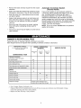
OWNER'S
RESPONSIBILITIES
Follow the hourly or calendar intervals, whichever occurs first.
More frequent service is required when operating in adverse conditions noted below.
HOURLY OPERATING
INTERVAL
MAINTENANCE
SCHEDULE
FILL IN DATES AS YOU COMPLETE
REGULAR SERVICE
Before Each
Use
MAINTENANCE
TASK
PRESSURE
WASHER
Check/clean
water inlet screen
Every 50
Hours or
Every 100
Hours or
Yearly
Yearly
xt
on quick-connect.
Check high pressure hose.
X
Check detergent
hose.
X
Check spray gun and assembly for leaks.
X
Purge pump of air and contaminants.
X
ENGINE
Check oil level.
X
X*
Change engine oil.
Service air cleaner.
X**
Service spark plug.
X
X
Service spark arrester
Prepare for storage.
1
Clean if clogged. Replace if perforated
*
Change oil after the first (5) operating
Prepare unit for storage if it is to
remain idle for longer than 30 days.
or torn.
hours and every 50 hours or every year, whichever
sooner when operating under dirty or dusty conditions.
**
SERVICE DATES
Replace more often under dirty or dusty conditions.
occurs first,thereafter.
Change
PRODUCT
SPECIFICATIONS
_
Pressure
Washer
Pressure ...................
Flow Rate ..................
Chemical Mix ...............
Water Supply Temperature .....
Engine
2,400 PSI
2.2 GPM
Use as directed
Not to Exceed 140°F
Check
Rated Horsepower ...........
Spark Plug Type: ...........
6.0 HP
Champion RJ19LM
or Equivalent
0.030 inches
(0.760ram)
1.6 Quarts
SAE 30
SAE 5W-30 orl0W-30
Set Gap To: .............
Gasoline Capacity ............
Oil Above 40°F .............
0°F - 40°F ...............
Check
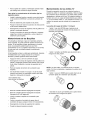
O-ring
1. Detach spray gun from high pressure hose. Detach
nozzle extension from spray gun and remove o-ring
and screen from nozzle extension. Flush the
screen, spray gun, and nozzle extension with clean
water to clear debris.
All service and adjustments should be made at least
once each season. Follow the requirements in the
"Maintenance Schedule" chart above.
2. If the screen is damaged, the o-ring kit contains a
replacement in-line filter screen and an o-ring. If
undamaged, reuse screen.
3. Place the in-line filter screen into the threaded end
of the nozzle extension. Direction does not matter.
Push the screen in with the eraser end of a pencil
until it rests flat at the bottom of the opening. Take
care to not bend the screen.
NOTE: Once a year you should clean or replace the
spark plug and replace the air filter. A new spark plug
and clean air filter assure proper fuel-air mixture and
help your engine run better and last longer.
EACH USE
•
Check water inlet screen for damage.
•
Check high pressure hose for leaks.
•
Check chemical filters for damage.
•
Check spray gun and nozzle extension assembly
for leaks.
•
Purge pump of air and contaminants.
4. Place the o-ring into the recess. Push the o-ring
snugly against the in-line filter screen.
5. Assemble the nozzle extension to the spray gun,
as described earlier in this manual.
Purge Pump of Air and Contaminants
To remove air from the pump, follow these steps:
PRESSURE WASHER
MAINTENANCE
Check
and Clean
Inlet Screen
High Pressure
•
Set up the pressure washer as described in the
ASSEMBLY section and connect the water supply.
•
Pull the trigger on the spray gun and hold until a
steady stream of water appears.
To remove contaminants from the pump, follow these
steps:
Examine garden hose inlet screen. Clean if it is
clogged or replace if it is torn.
Check
Filter
Nozzle Extension
Some adjustments will need to be made periodically to
properly maintain your pressure washer.
Check engine oil level.
In-Line
In-line Filter
RECOMMENDATIONS
•
Extension
Refer to the illustration and service the in-line filter if it
becomes clogged, as follows:
The pressure washer's warranty does not cover items
that have been subjected to operator abuse or
negligence. To receive full value from the warranty,
the operator must maintain pressure washer as
instructed in this manual.
BEFORE
Gun and Nozzle
Examine hose connection to spray gun and make sure
it is secure. Test trigger by pressing it and making
sure it springs back into place when you release it. Put
safety latch in UP position and test trigger. You should
not be able to press trigger. Replace spray gun
immediately if it fails any of these tests.
Specifications
GENERAL
ANGER:withNever
repairexceeds
a high pressure
hose.
Replace
hose that
the maximum
pressure rating of your pressure washer.
Specifications
Hose
High pressure hoses can develop leaks from wear,
kinking, or abuse. Inspect hose before each use.
Check for cuts, leaks, abrasions, bulging of cover, or
damage or movement of couplings. If any of these
conditions exist, replace hose immediately.
10
•
Set up the pressure washer as described in the
ASSEMBLY section, and connect the water supply.
•
Remove the nozzle extension from the spray gun.
•
Start the engine according to instructions in
OPERATION section.
•
Disengage the safety latch and pull the trigger on
the spray gun and hold.
• Whenthewatersupplyis steadyandconstant,
engagethesafetylatchandrefastenthenozzle
extension.
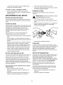
Nozzle
Maintenance
O
If a nozzle becomes restricted or clogged with dirt or
foreign materials, a pulsing sensation during use may
occur. This is caused by excessive pump pressure.
Immediately clean a clogged or partially restricted
nozzle with the kit included with your pressure washer
by following these instructions:
•
Shut off the engine and turn off the water supply.
•
Disengage the safety latch and pull the trigger on
the spray gun and hold until all water is purged
from the unit. Engage the safety latch on the spray
gun.
Remove the nozzle from the end of the nozzle
extension.
•
•
1 o-ring, yellow, (p/n B2264) for the end of the
high pressure hose.
Use the wire included in the kit or a small paper
clip to free the foreign materials clogging or
restricting the nozzle.
Use wire here to
remove
debris.
,.JL__
_
NOTE: The previous two o-rings are close in size.
1 o-ring, blue, (p/n B3065) for the inside of the
nozzle extension quick connect.
Please match carefully to assure proper o-ring usage.
__
•
Remove additional debris by rinsing out the nozzle.
Rinse between 30 to 60 seconds.
•
Reinstall the nozzle into the nozzle extension.
•
Reconnect the water supply, turn on the water, and
start the engine.
•
Disengage safety latch on the spray gun.
•
Test the pressure washer.
O-Ring
1 rubber washer, (p/n B2385) for the inside of the
garden hose connector.
Maintenance
Through the normal operation of your pressure
washer, o-rings keep the connections of the hoses
and spray gun tight and leak-free. They may become
worn or damaged with use.
Provided with your pressure washer is an O-Ring
Maintenance Kit which includes replacement o-rings,
rubber washer and water inlet filter. Refer to the
instruction sheet provided in the kit to service your
unit's o-rings. Note that not all of the parts in the kit
will be used on your unit.
•
Parts in the O-Ring Kit Include:
•
1 o-ring, red, (p/n B2726) for the end of the spray
gun connection between spray gun and nozzle
extension.
1 water inlet screen (p/n B2384) for the garden
hose connector.
To remove a worn or damaged O-Ring:
•
11
Use a small flathead screwdriver to get underneath
the o-ring to gently pry it off.
ENGINE MAINTENANCE
Replace
Checking
Replace the spark plug yearly or every 100 hours of
operation.
Oil Level
Spark Plug
Oil level should be checked prior to each use or at
least every 5 hours of operation. Keep oil level
maintained.
,_
Changing
•
Clean area around spark plug and remove.
•
For replacement use Champion RJ19LM or
equivalent.
•
Check electrode gap with wire feeler gauge and set
gap at 0.030 inches (0.76mm), if necessary.
•
Install spark plug, tighten securely.
Oil
Change engine oil after the first 5 hours and every
50 hours or annually thereafter. If you are using your
pressure washer under extremely dirty or dusty
conditions, or in extremely hot weather, change oil
every 25 hours.
CAUTION:
Disconnect
from
spark
plug and
keep wirespark
away plug
fromwire
spark
plug.
Change oil while engine is still warm from running, as
follows:
•
•
Remove drain plug from the bottom of engine.
Drain oil into a suitable container. When crankcase
is empty, replace drain plug in engine.
•
Slowly pour oil into oil fill opening. Replace and
tighten dipstick, remove and check oil level. Oil
level should be at "Full" mark on dipstick. Do Not
overfill above that mark.
•
When engine crankcase is filled to proper level,
install and tighten oil cap/dipstick.
•
Wipe up any remaining oil.
Service
Carburetor
If you think your carburetor needs adjusting, see your
nearest Sears service center. Engine performance
may be affected at altitudes above 4000 feet. For
operation at higher elevations, contact your nearest
Sears service center.
Air Cleaner
Your engine will not run properly and may be
damaged if you run it with a dirty air cleaner.
Service the air cleaner once every 100 hours of
operation or once each year, whichever comes first.
Service more often if operating under dirty or dusty
conditions. Replacements are available at your local
Sears service center.
Spark Arrester
Your engine is not factory-equipped with a spark
arrester. In some areas, it is illegal to operate an
engine without a spark arrester. Check local laws and
regulations. A spark arrester is available from your
nearest Sears service center. For the part number call
1-800-366-PART.
To service the air cleaner, follow these steps:
• Remove screws and lift cover.
•
•
Carefully remove pre-cleaner and cartridge
assembly.
After servicing pre-cleaner and cartridge, assemble
pre-cleaner on cartridge.
•
Install pre-cleaner/cartridge
•
Place cover on air cleaner and tighten screws
securely to base.
Service
The spark arrester must be serviced every 50 hours to
keep it functioning as designed.
If the engine has been running, the muffler will be very
hot. Allow the muffler to cool before servicing the
spark arrester.
in base.
12
•
Remove spark arrester screen for cleaning and
inspection.
•
Replace if screen is damaged.
AFTER EACH USE
•
Water should not remain in the unit for long periods of
time. Sediments or minerals can deposit on pump
parts and "freeze" pump action. Follow these
procedures after every use:
Connect a 3-foot section of garden hose to the
water inlet adapter. Pour RV-antifreeze (antifreeze
without alcohol) into the hose. Pull the recoil handle
twice. Disconnect 3-foot hose.
•
Properly dispose of leftover antifreeze.
•
LONG TERM STORAGE
Flush detergent siphoning tube by placing the filter
into a pail of clean water while running pressure
washer in low pressure mode. Flush for one to two
minutes.
•
Shut off the engine and let it cool, then remove all
hoses.
•
Disconnect spark plug wire from spark plug.
•
Empty the pump of all liquids by pulling recoil
handle about 3 times. This should remove most of
the liquid in the pump.
•
Coil the high pressure hose and inspect it for
damage. Cuts in the hose or fraying could result in
leaks and loss of pressure. Should any damage be
found, replace the hose. Do Not attempt to repair a
damaged hose. Replace the hose with the genuine
Craftsman part.
If you do not plan to use the pressure washer for more
than 30 days, you must prepare the engine for long
term storage.
It is important to prevent gum deposits from forming in
essential fuel system parts such as the carburetor, fuel
filter, fuel hose or tank during storage. Also,
experience indicates that alcohol-blended fuels (called
gasohol, ethanol or methanol) can attract moisture,
which leads to separation and formation of acids
during storage. Acidic gas can damage the fuel
system of an engine while in storage.
Protect
Fuel System
Fuel Additive:
•
Drain water from hose and properly hang it on the
wire support provided.
•
Reconnect spark plug wire to spark plug.
If adding
gasoline.
promote
fuel can
•
Store unit in a clean, dry area.
•
Add fuel additive following manufacturer's
instructions.
•
Make sure you have water supply to pump inlet
connected and turned ON.
•
Run the engine outdoors for 10 minutes to be sure
that treated gasoline has replaced the untreated
gasoline in the carburetor.
,_
DANGER:
engine with
fuel in
the
gas tank Never
indoorsstore
or inthe
enclosed,
poorly
ventilated areas where fumes may reach an
open flame, a spark, or pilot light.
WINTER
STORAGE
a fuel additive, fill the fuel tank with fresh
If only partially filled, air in the tank will
fuel deterioration during storage. Engine and
be stored up to 24 months with additive.
If fuel additive is not used, remove all fuel from tank
and run engine until it stops from lack of fuel.
_
AUTION:
You must protect
from
freezing
temperatures.
Failure your
to dounit
so will
permanently damage your pump and render
your unit inoperable.
Change
Oil
To protect the unit from freezing temperatures:
While engine is still warm, not hot, drain oil from
crankcase. Refill with recommended grade. See
"Changing Oil" section.
•
Oil Cylinder
Flush detergent siphoning tube by placing the filter
into a pail of clean water while running pressure
washer in low pressure mode. Flush for one to two
minutes.
•
Disconnect hose connected to chemical inject
fitting on the pump.
•
Empty the pump of all pumped liquids by pulling
recoil handle about 3 times. This should remove
most of the liquid in the pump.
Bore
•
Remove spark plug. Squirt about 1/2 ounce of
clean engine oil into the cylinder. Cover spark plug
hole with rag. Pull recoil handle slowly to distribute
oil. Avoid spray from spark plug hole.
•
Install spark plug. Do Not connect spark plug wire.
IMPORTANT: Never cover your pressure washer
while engine and exhaust area are warm.
13
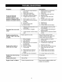
Problem
Cause
1.
Pump has following
problems: failure to
produce pressure, erratic
pressure, chattering, loss of
pressure, low water volume.
2.
3.
4.
5.
Correction
Low pressure nozzle (black) is
being used.
Water inlet is blocked.
Inadequate water supply.
Inlet hose is kinked or leaking.
Clogged inlet hose strainer.
6.
7.
1.
2.
3.
4.
5.
Water supply is over 140°F.
High pressure hose is blocked
or leaks.
8. Gun leaks.
9. Nozzle is obstructed.
10. Pump is faulty.
6.
7.
1.
1.
Detergent siphoning tube is not
submerged.
Chemical filter is clogged.
Replace with any of the three
high pressure nozzles.
Clear inlet.
Provide adequate water flow.
Replace hose.
Check and clean inlet hose
strainer.
Provide cooler water supply.
Clear blocks in outlet hose.
8. Replace gun.
9. Clean nozzle.
10. Contact Sears service facility.
Detergent fails to mix with
spray.
2.
Engine runs good at noload but "bogs" when load
is added.
Engine speed is too slow.
Move throttle control to FAST
position. If engine still "bogs down",
contact Sears service facility.
1.
2.
3.
4.
1.
2.
3.
4.
Clean or replace air cleaner.
Fill fuel tank.
Drain gas tank; fill with fresh fuel.
Connect wire to spark plug.
5.
6.
7.
Replace spark plug.
Drain gas tank; fill with fresh fuel.
Open choke fully and crank
engine.
Contact Sears service facility.
Contact Sears service facility.
Engine will not start; or
starts and runs rough.
3.
5.
6.
7.
A high pressure nozzle is being
used.
Dirty air cleaner.
Out of gasoline.
Stale gasoline.
Spark plug wire not connected
to spark plug.
Bad spark plug.
Water in gasoline.
Overchoking.
8.
9.
2.
Insert detergent siphoning tube
into detergent.
Clean or replace filter/detergent
siphoning tube.
Replace with low pressure (black)
nozzle.
3.
White smoke from exhaust.
Intake valve stuck open or
closed.
10. Engine has lost compression.
8.
9.
Engine shuts down during
operation.
Out of gasoline.
Fill fuel tank.
Engine lacks power.
Dirty air filter.
Replace air filter.
Engine "hunts"
Choke is opened too soon.
Move choke to halfway position until
engine runs smoothly.
or falters.
14
10. Contact Sears service facility.
15
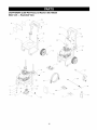
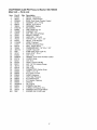
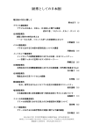
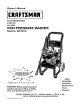
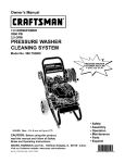
CRAFTSMAN
2,400 PSI Pressure
Main Unit -- Exploded View
Washer
580.768330
31
_\\
\\
6
/
"
/
5O
24
t
\
\
\
\
\
\
/
28
_16
_17
/
/
44
4O
_21
\
_52
16
41
CRAFTSMAN
2,400 PSI Pressure
Main Unit m Parts List
Item
2
3
4
5
6
7
8
9
10
11
12
13
14
15
16
17
18
19
20
21
23
24
25
26
27
28
29
30
31
32
34
35
36
37
38
39
40
41
42
43
44
900
PaN #
Qty.
B1932
1
96307
1
EB5654
1
50190
2
B5670
1
30809
5
B1631B
1
B4966
2
75402C
2
52858
2
27007
2
39288
2
75246
3
B4163
1
A1040B
1
A1041
1
B2218
1
31669
1
48031G
1
NSP
1
23707
4
B1460
1
EB5676
1
B1779
2
B2347
2
B2759
1
B2071
2
46476
2
B2516
3
21424
1
B5689
1
B5646
1
B3858
1
B3263
1
B5830
1
B2509
1
B5658
1
AB3061B
1
B4224
1
97837
1
92479
4
NSP
1
Washer
580.768330
Description
DECAL, Instructions
DECAL, 1-800 Number
BASE, Polo Green Powder Coated
WASHER, .34" x 1" Flat
DECAL, Unit 1433-0
GROMMET, Rubber
BILLBOARD
TIRE, Metal Hub 10"
PUSHNUT, 5/8"
NUT, M8 Locking Flange
MOUNT, Vibration
HHCS, M8- 1.25 x 55
TAPTITE, 3/8"- 16 x 1-1/4"
DECAL, 4 QD Nozzles
HOSE, Chemical
FILTER, Chemical Hose
SEAL, Engine Donut
CARRIAGE BOLT, 1/4"-20 x 1 3/4"
CLAMP, Hose 3/8"
PUMP (See pages 18 & 19)
SHCS, 5/16" - 24 x 1"
CAP, Vinyl
HANDLE, Polo Green Powder Coated
COVER, Hinge
CAP, End
HOOK, Chemical Bottle
NUT, 1/4"-20 Locking Flange
CAP, Plug
CAP, Vinyl
CONNECTOR, Garden Hose
HOSE, 1/4" x 30'
KIT, Quick Connect
WAND, Extension
GUN, High Pressure
KIT, Maintenance
KIT, Nozzle, Cleaning
MANUAL
OIL, Engine
SCREEN, Gun Inlet
O-RING, Hi Pressure Trns.
WASHER, M8 Conical Ribbed
ENGINE, B & S, 6HP Intek
17
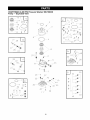
CRAFTSMAN
2,400 PSI Pressure
Pump m Exploded View
.-_--_ _
15
1
Washer
580.768330
L
o
3
1----- 0
21
//
o
_0
2
/
0_1
o
o--43
©
4
/
_/
21
½
29
9_
11
25
/
27
26
/
24
28 ½
22
25
_¢1_
18..
21
20_
0
S
32
t @
10
\44
32
55
t _
33
11
-Iy;
33
45
18
CRAFTSMAN
2,400 PSI Pressure
Pump m Parts List
Item
1
2
3
4
5
6
7
8
9
10
11
12
PaN #
B2218
97962
B5710
97835
21783
93680
97831
B2702
B4813
97841
40946
185710
......
......
......
13
14
15
16
17
18
19
20
21
22
28
23
21
24
25
26
27
29
......
......
......
......
185287
......
......
......
......
......
......
185711
......
......
......
......
......
......
Qty
1
3
1
1
1
3
3
1
1
3
4
0
1
3
1
1
2
3
1
0
1
1
1
1
1
1
0
1
1
1
1
1
1
Washer
580.768330
Description
O-RING, 1.625 ID x .103
SHCS, M6- 1 x25
VALVE, 1/8 npt 1-5 PSI
O-RING, Housing Seal
THERMAL RELIEF, GPW-EG
SEAL, Oil Piston
SPACER, Pilot
HOUSING, Piston
ADAPTER, Engine
CAP, Outlet Check Valve
SHCS, M6-1.0 x 35
KIT, AXIAL CAM
O-RING, Engine Seal
SHCS, M6- 1 x 25
O-RING, Housing Seal
WASHER, Brg. 36 x 65 x 6Thk
ASSY., Brg. Cage 45 x 65
WASHER, Brg. 45 x 65 x 1
CAM, Axial 5.6 7/8"SAE
KIT, CHEM INJECT
FITTING, Chem Inject
BALL, Chem Inject
SPRING, Chem Inject
O-RING, Venturi & Seat, Black
VENTURI, Chem Inject
O-RING, Venturi, Yellow
KIT, UNLOADER 2300
O-RING, Venturi & Seat, Black
CAP, Unloader
O-RING, Unloader Cap
SPRING, Unloader
PISTON, Unloader
SEAT, Unloader
Item
31
11
32
33
45
34
11
35
36
46
37
1
2
4
38
39
40
41
1
2
4
6
11
21
25
28
32
42
43
Part#
185712
Description
KIT, CHECK VALVES
SHCS, M6-1.0 x 35
O-RING, Check Valve
ASSY., Check Valve
O-RING, Check Valve, White
185531
KIT, HEAD BRASS EG
SHCS, M6-1.0 x 35
HEAD, Pump
PLUG, 1/8-28
WASHER, M6 Flat
185713
KIT, PISTON & SPRING
O-RING, Engine Seal
SHCS, M6- 1 x 25
O-RING, Housing Seal
RETAINER, Piston Spring
PISTON, Dia. 15 x 65 Lg
SPRING, Piston Return
185714
KIT, O-RING/SEAL 2300
O-RING, Engine Seal
SHCS, M6- 1 x 25
O-RING, Housing Seal
SEAL, Oil Piston
SHCS, M6-1.0 x 35
O-RING, Venturi & Seat, Black
O-RING, Unloader Cap
O-RING, Venturi, Yellow
O-RING, Check Valve
SEAL, Double-Lip
O-RING, High Pressure
Transfer
44
3
O-RING, Outlet CV Cap
45
3
O-RING, Check Valve, White
Item numbers 12, 17, 23, 31, 34, 37, and 41 are service
kits and include all parts shown within the box. Certain
parts may only be available as components of a kit.
19
Qty
0
4
3
6
3
0
4
1
1
4
0
1
3
1
3
3
3
0
1
3
1
3
4
2
1
1
3
3
1
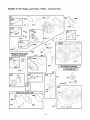
ENGINE,
6.0 HP, Briggs
and Stratton,
120612 - Exploded
View
I_TRUCT1ON MAN_L_
1102 _
i_
_3
.............51
2O
_I_U
¸!
13
ENGINE,
6.0 HP, Briggs
and Stratton,
120612 - Exploded
View
365
! _tS
............................................
27s
27_
_3A
........
_
_ _,,_
:
........
,, {._:;!
IJ ._....
_"1
836A
2,87 _
il
ii;
;i_- _!i
21
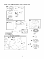
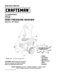
ENGINE,
6.0 HP, Briggs
and Stratton,
120612 - Exploded
View
60
601
78 _:::i!?,
J f_ ,,,_i%
,
i;03,6 E_IONS
LABEL
• 3;2
}
,_,,_,
363
7
,
23
22
_,d _,_'
ENGINE,
Item
1
2
3
4
5
7
8
9
10
11
12
13
15
16
20
22
23
24
25
25
25
25
26
26
26
26
27
28
29
32
33
34
35
36
37
40
43
45
46
51
55
58
60
65
78
95
97
104
108
109
117
121
122
125
127
130
133
134
137
146
155
163
187
188
189
190
202
209
222
227
238
276
287
300
304
305
306
307
332
333
Part#
692670
399269
299819
498983
694328
695166
495786
272481
691125
691260
692232
691137
691680
691457
399781
691092
692693
222698
690021
694167
694168
694169
499631
692785
692786
692787
691866
499423
499424
691664
499642
499641
691304
691304
694086
692194
691997
690977
694039
692668
691421
693389
281434
690837
691108
691636
499682
691242
691182
693866
498981
695190
692799
694204
694468
691203
398187
398188
693981
690979
695168
692667
691050
691147
694543
690940
691303
691290
693378
691467
691300
271716
690940
694248
499676
691108
691232
690345
690662
802574
6.0 HP, Briggs
and Stratton,
120612 - Parts List
Description
Cylinder Assembly
Bushing/Seal Kit (Magneto Side)
Oil Seal
Engine Sump
Cylinder Head
Cylinder Head Gasket
Breather Assembly
Breather Gasket
Screw (Breather Assembly)
Breather Tube
Crankcase Gasket
Screw (Cylinder Head)
Oil Drain Plug
Crankshaft
Oil Seal (PTO Side)
Screw (Engine Sump)
Flywheel
Flywheel Key
Piston Assembly (Standard)
Piston Assembly (.010 O.S.)
Piston Assembly (.020 O.S.)
Piston Assembly (.030 O.S.)
Ring Set (Standard)
Ring Set (.010 O.S.)
Ring Set (.020 O.S.)
Ring Set (.030 O.S.)
Piston Pin Lock
Piston Pin
Connecting Rod
Screw (Connecting Rod)
ExhaustValve
Intake Valve
Valve Spring (Intake)
Valve Spring (Exhaust)
Flywheel Guard
Valve Retainer
Governor/Oil Slinger
Valve Tappet
Camshaft
Intake Gasket
Rewind Starter Housing
Starter Rope
Starter Rope Grip
Screw (Rewind Starter)
Screw (Flywheel Guard)
Screw (Throttle Valve)
Throttle Shaft
Float Hinge Pin
ChokeValve
Choke Shaft
Main Jet
Carburetor Overhaul Kit
Carburetor Spacer
Carburetor
Welch Plug
Throttle Valve
Carburetor Float
Needle/Seat Kit
Gasket-Float Bowl
Timing Key
Cylinder Head Plate
Air Cleaner Gasket
Fuel Line
Screw (Control Bracket)
Rocker Arm Ball
Screw (Fuel Tank)
Mechanical Governor Link
Governor Spring
Control Bracket
Governor Control Lever
Valve Cap
Sealing Washer
Screw (Dipstick Tube)
Muffler-Exhaust
Housing-Blower
Screw (Blower Housing)
Cylinder Shield
Screw (Cylinder Shield)
Nut (Flywheel)
Armature-Magneto
Item
334
337
356
358
363
365
383
404
425
443
443A
445
455
456
459
472
505
523
524
525
529
562
564
584
585
592
597
601
604
608
613
613A
615
616
619
621
633
635
670
684
689
692
708
718
741
830
832
836
836A
842
843
847
851
868
883
914
930
957
966
968
972
975
976
977
993
1005
1019
1022
1023
1026
1029
1034
1036
1058
1059
1095
1102
1210
1211
23
Part #
691061
692051
692390
695189
19069
691136
19374
690272
690670
692523
691637
491588
691219
281503
281505
693809
231082
499621
280966
495265
691923
94852
693808
692342
691879
690800
690297
95162
693807
497680
691108
691140
690340
691306
691108
692310
693867
66538
692294
690345
691855
690572
691321
690959
691830
694544
691466
692198
690664
691031
691884
692047
493880
498592
691893
691108
692675
692046
693863
692298
499618
493640
496115
692704
694088
691346
693868
691890
499624
692045
691230
691343
694507
274264
692311
692705
691255
498144
498144
Description
Screw (Magneto Armature)
Sparkplug
Wire-Stop
Engine Gasket Set
Flywheel Puller
Screw (Carburetor)
Wrench-Sparkplug
Washer (Governor Crank)
Screw (Air Cleaner Cover)
Screw (Air Cleaner Primer Base)
Screw (Air Cleaner Primer Base)
Filter- Air Cleaner Cartridge
Cup-Flywheel
Retainer-Spring
Plate-Pawl Friction
Choke Shaft Knob
Nut (Governor Control Lever)
Dipstick
Dipstick Tube Seal
Dipstick Tube
Grommet
Bolt (Governor Control Lever)
Screw (Control Cover)
Breather Passage Cover
Breather Passage Gasket
Nut (Rewind Starter)
Screw (Pawl Friction Plate)
Clamp-Hose
Cover-Control
Starter-Rewind
Screw (Exhaust Muffler)
Screw (Exhaust Muffler)
Retainer-Governor
Shaft
Crank-Governor
Screw (Cylinder Head Plate)
Switch-Stop
Choke Shaft Seal
Boot-Sparkplug
Spacer-Fuel Tank
Screw (Breather Passage Cover)
Spring-Friction
Detent Spring
Seal-Dust
Pin-Locating
Gear-Timing
Stud (Rocker Arm)
Guard-Muffler
Screw (Muffler Guard)
Screw (Muffler Guard)
Dipstick/Tube Seal
Sleeve-Lever
Dipstick/Tube Assembly
Terminal-Cable
Seal-Valve
Gasket-Exhaust
Screw (Rocker Cover)
Guard-Rewind
Cap-Fuel Tank
Base- Air Cleaner Primer
Cover-Air Cleaner
Fuel Tank
Bowl-Float
Primer-Carburetor
Gasket Set-Carburetor
Cylinder Head Plate Gasket
Fan-Flywheel
Label Kit
Gasket-Rocker Cover
Cover-Rocker
Rod-Push
Rocker Arm
Guide-Push Rod
Label-Emissions
Owner's Manual
Screw/Washer Kit
Valve Gasket Set
Guide Pilot
Pulley/Spring Assembly (Pulley)
Pulley/Spring Assembly (Spring)
Your Warranty
If you have any questions regarding your warranty rights
and responsibilities, your should contact your nearest
authorized service center or call Sears at
1-800-473-7247.
Rights and Obligations
The California Air Resources Board ("CARB") and Sears
Roebuck and Co., USA, are pleased to explain the Emission
Control System Warranty on your model year 2000 and later
small off-road engine (engine). In California, new engines
must be designed, built and equipped to meet the State's
stringent anti-smog standards. Sears must warrant the
emission control system on your engine for the periods of
time listed below provided there has been no abuse, neglect,
or improper maintenance of your engine.
Warranty
Any warranted part which is not scheduled for replacement
as required maintenance, or which is scheduled only for
regular inspection to the effect of "repair or replace as
necessary" shall be warranted for 2 years. Any warranted
part which is scheduled for replacement as required
maintenance shall be warranted for the period of time up to
the first scheduled replacement point for that part.
Your emission control system includes parts such as the
carburetor and the ignition system.
Where a warrantable condition exists, Sears will repair your
engine at no cost to you. Expenses covered under under
warranty include diagnosis, parts, and labor.
Manufacturer's
Warranty
Diagnosis
The owner shall not be charged for diagnostic labor which
leads to the determination that the warranted part is
defective if the diagnostic work is performed at an approved
Sears service center.
Coverage
The model year 2000 and later engines are warranted for
two years. If any emission related part on your engine (as
listed below) is defective, the part will be repaired or
replaced by Sears.
Owner's
Warranty
Consequential
Responsibilities
WHAT IS NOT COVERED
All failures caused by abuse, neglect, or improper
maintenance are not covered.
Add-on
If you have any questions regarding your warranty rights and
responsibilities, you should contact your nearest authorized
service center or call Sears at 1-800-473-7247.
Where
If you have any questions regarding your warranty rights and
responsibilities, you should contact your nearest authorized
service center or call Sears at 1-800-473-7247.
Date
Service
Maintenance,
Replacement
Emission Related Parts
and Repair of
Any Sears approved replacement part used in the
performance of any warranty maintenance or repair on
emission related parts will be provided without charge to the
owner if the part it under warranty.
of Coverage
Sears warrants to the initial owner and each subsequent
purchaser that the engine is free from defects in materials
and workmanship which cause the failure of a warranted
part for a period of two years.
Emission
Control Warranty
Parts List
1. Carburetor Assembly
WHAT IS COVERED
•
to Get Warranty
Warranty services or repairs shall be provided at all Sears
authorized service centers.
The warranty period begins on the date the engine is
delivered.
Repair or Replacement
Parts
How to File a Claim
You are responsible for presenting your engine to a Sears
authorized repair center as soon as a problem exists.
Warranty repairs should be completed in a reasonable
amount of time, not to exceed 30 days.
Length
or Modified
The use of add-on or modified parts can be grounds for
disallowing a warranty claim. Sears is not liable to cover
failures of warranted parts caused by the use of add-on or
modified parts.
As the engine owner, you should be aware that Sears may
deny you warranty coverage if your engine or a part of it has
failed due to abuse, neglect, improper maintenance,
unapproved modifications, or the use of parts not made or
approved by the original equipment manufacturer.
Commencement
Damages
Sears may be liable for damages to other engine
components caused by the failure of a warranted part still
under warranty.
As the engine owner, you are responsible for the
performance of the required maintenance listed in this
owners manual. Sears recommends that you retain all
receipts covering maintenance on your engine, but Sears
cannot deny warranty solely due for the lack of receipts or
for your failure to ensure the performance of all scheduled
maintenance.
Warranty
Period
2.
Ignition System
a.
of Parts
Spark Plug, covered up to maintenance
b.
Ignition Module
3. Crankcase Breather Tube
Repair or replacement of any warranted part will be
performed at no charge to the owner at an approved
Sears service center.
4.
24
Exhaust Manifold
schedule.
GARANTIA ..............................
INSTRUCCIONES DE SEGURIDAD
MONTAJE ............................
OPERACION ..........................
MANTENIMIENTO
......................
GARANTIA
LIMITADA
.........
25
25-26
27-28
29-32
32-35
DE LA MAQUINA
ESPECIFICACIONES
......................
33
ALMACENAMIENTO
.......................
36
REPARAClON DE DANOS REPUESTOS .......
38
GARANTIA DEL CONTROL DE EMISlONES
.... 39
COMO ORDENAR PARTES . PAGINA POSTERIOR
LAVADORA
DE ALTA
PRESION
CRAFTSMAN
Durante un a_o a partir de la fecha de compra, Sears reparara, sin cargo alguno, cualquier defecto en material y mano de
obra, siempre y cuando esta maquina lavadora de alta presi6n Craftsman haya sido mantenida y puesta en funcionamiento
de acuerdo alas instrucciones suministradas en el manual del propietario.
Si esta maquina lavadora es usada para fines comerciales, la garantia se aplicara tan solo por 90 dias a partir de la fecha
de compra. Siesta maquina lavadora de alta presi6n es usada para alquiler, la garantia se aplicara tan solo por 30 dias
despu6s de la fecha de compra.
Esta garantia no cubre:
•
Elementos perecederos como bujias o filtros de aire, los cuales se desgastan con el uso normal.
•
Reparaciones necesarias debido al abuso o negligencia del operador, incluyendo daSos ocasionados pot la ausencia de
suministro de agua a la bomba o pot no mantener el equipo de acuerdo alas instrucciones contenidas en el manual del
propietario.
El servicio de garantia se hace efectivo devolviendo
Sears mas cercano en los Estados Unidos.
la maquina lavadora de alta presi6n al centro de servicio o distribuidor
Esta garantia le proporciona derechos legales especificos;
estado a estado.
Sears,
Roebuck
usted tambi6n puede tener otros derechos, los cuales varian de
and Co., Dept. 817 WA, Hoffman
Am lr,-1
m vj :(m
,_
El escape del motor de este producto contiene
elementos quimicos reconocidos en el Estado
de California por producir cancer, defectos de
nacimiento u otros dahos de tipo reproductivo.
Estates,
IL 60179
gasolina
es altamente
INFLAMABLE
yiPELIGRO!
sus vapores La
son
EXPLOSIVOS.
No permita
que
fumen, que existan llamas abiertas, chispas o calor a
su alrededor cuando manipule gasolina. Evite regar
gasolina sobre un motor caliente. Permita que la
unidad se enfrie antes de volver a colocarle
combustible. Cumpla con todas las leyes que regulan
el almacenamiento y el manejo de gasolina.
iPRECAUCION!
Cuando transporte, instale, ajuste
o haga reparaciones a su maquina lavadora de alta
presi6n, siempre desconecte el alambre de la bujia y
col6quelo donde no pueda entrar en contacto con la
bujia.
Lea este manual minuciosamente y conozca a fondo las
partes y el funcionamiento de su maquina lavadora a
presion. Conozca sus aplicaciones, sus limitaciones y
los peligros involucrados.
iPELIGRO!
Los gases del sistema de escape del
motor contienen gas de mon6xido de carbono
MORTAL. Si este gas peligroso se inhala en
concentraciones suficientes, puede causar p6rdida de
la consciencia o incluso la muerte. Opere este equipo
Qnicamente al aire libre, donde exista ventilaci6n
adecuada.
25
•
Coloque esta maquina lavadora a presi6n en Areas
alejadas de materiales combustibles, humos o polvo
combustibles.
•
El equipo de alta presi6n esta diseSado para set utilizado
UNICAMENTE con las partes autorizadas Sears. Si
utiliza este equipo con partes que no cumplan con las
especificaciones minimas, el usuario asume todos los
riesgos y responsabilidades.
•
Algunos quimicos o detergentes pueden ser nocivos si se
inhalan o ingieren, causando nausea severa, desmayos o
envenenamiento. Los elementos nocivos pueden
ocasionar daSo a la propiedad o lesiones severas.
•
Nunca mueva la maquina halando la manguera de alta
presi6n. Utilice la manija que viene con la unidad.
•
Siempre asegerese de que la pistola de rociado,
boquillas y accesorios est6n conectados correctamente.
No permita en ningQn momento que NINOS operen la
maquina lavadora a presi6n.
•
No asegure la pistola de rociado en la posici6n (open =
abierto).
Opere el motor Qnicamente a la velocidad de mando.
Hacer funcionar el motor a velocidades excesivas
aumenta el riesgo de lesiones personales. No juegue con
partes que puedan aumentar o disminuir la velocidad de
mando.
•
El rociado de alta presi6n puede daSar elementos
fragiles, incluyendo el vidrio. No apunte la pistola de
rociado al vidrio cuando est6 en el modo de rociado a
chorro.
Sostenga firmemente en su mano la manguera de
rociado antes de poner en marcha la unidad. De no
hacerlo, podrian ocurrir lesiones por el movimiento
brusco de la pistola de rociado. No abandone la pistola
de rociado cuando la maquina est6 en funcionamiento.
No use ropa suelta, joyas o elementos que puedan
quedar atrapados en el arranque o en otras partes
rotatorias.
Antes de poner en marcha la maquina lavadora a presi6n
en clima frio, revise todas las pares del equipo y
asegQrese de que no se haya formado hielo sobre elias.
•
Nunca utilice una pistola de rociado que no tenga un
seguro para gatillo o protecci6n para gatillo en su lugar y
en buenas condiciones.
El area de limpieza debera tener inclinaciones y drenajes
adecuados para disminuir la posibilidad de caidas debido
a superficies resbalosas.
•
Mantenga conectada la manguera a la maquina o a la
pistola de rociado cuando el sistema est6 presurizado. Es
peligroso desconectar la manguera cuando la unidad
esta presurizada.
Mantenga el chorro del agua alejado de alambrados
el6ctricos, de Io contrario podrian ocurrir descargas
el6ctricas fatales.
•
No eluda ningen dispositivo de seguridad de esta
maquina.
•
El silenciador y el motor se calientan durante el
funcionamiento y permanecen calientes inmediatamente
despu6s del apagado. Evite el contacto con silenciadores
o motores calientes, o podria quemarse severamente.
•
Opere y almacene esta unidad sobre una superficie
estable.
•
La manguera de alta presi6n puede desarrollar fugas
debido al desgaste, dobleces, abuso, etc. El agua que
sale de una fuga es capaz de inyectar materiales en la
piel. Inspeccione la manguera siempre que la vaya a
usar. Revise todas las mangueras para ver si presentan
cortes, fugas, abrasiones o deformaci6n de la cubierta,
daSo o movimiento de acoplamientos. Si existe
cualquiera de estas condiciones, remplace la manguera
inmediata-mente. Nunca repare la manguera de alta
presi6n. Remplacela con una manguera que tenga la
misma capacidad de presi6n maxima de su unidad.
•
El silenciador y el depurador de aire deberan estar
instalados y en buenas condiciones antes de operar la
maquina lavadora a presi6n. Estos componentes actean
como apagachispas si el motor presenta contrafuegos.
NUNCA deberan ser operadas las unidades con partes
rotas o ausentes, o sin la caja o cubiertas de protecci6n.
Revise que el sistema de combustible no presente fugas
o signos de deterioro, como mangueras desgastadas o
porosas, sujetadores flojos o ausentes, tapa o tanque
dafiados. Corrija todos los defectos antes de operar la
maquina lavadora a presi6n.
No rocie liquidos inflamables.
Utilice un respirador o mascara siempre que exista la
posibilidad de inhalar vapores. Lea todas las
instrucciones de la mascara para asegurarse de que le
brindara la protecci6n necesaria contra la inhalaci6n de
vapores nocivos.
Nunca apunte la pistola a la gente, animales o plantas.
La corriente de agua de alta presi6n que produce este
equipo pueden perforar la piel y sus tejidos profundos,
ocasionando lesiones serias y posible amputaci6n.
Nunca permita que pares del cuerpo entren en contacto
con la corriente del fluido. No entre en contacto con la
corriente del fluido creada por una fuga en la manguera
de alta presi6n.
En el estado de California es obligatorio, segen la ley, el uso
de apagachispas (Secci6n 4442 del C6digo de Recursos
Peblicos de California). Otros estados pueden tener leyes
similares. Las leyes federales se aplican en tierras
federales.
Siempre use protecci6n para los ojos cuando utilice este
equipo o cuando est6 cerca de donde se est6 usando el
equipo.
El rociado de alta presi6n puede hacer que particulas
pequeSas de pintura u otras particulas salgan disparadas
y viajen a altas velocidades.
NOTA: Si equipa el silenciador con un apagachispas, este
debera ser mantenido en buenas condiciones de trabajo.
Usted puede ordenar el apagachispas a trav6s de su
distribuidor de servicio autorizado Sears.
No opere la maquina lavadora a presi6n con un valor de
presi6n superior a su clasificaci6n de presi6n.
,_
PELIGROS
DE LESION
EL PERSONAL.
SIGA
LAS INDICARLE
INSTRUCCIONES
DE TODOS
ESTE ES ELPOTENCIALES
SIMBOLO DE ALERTA
DE PARA
SEGURIDAD.
ES USADO
PARA
SITUACIONES
CONLOS
MENSAJES DE SEGURIDAD QUE APARECEN DESPUES DE ESTE SIMBOLO PARA EVITAR POSIBLES
LESIONES O MUERTE.
26
Su maquina lavadora a presi6n requiere de cierto ensamble
y estara lista para ser usada enicamente despu6s de haber
depositado el combustible y el aceite recomendado.
MONTAJE DE LA MAQUINA
LAVADORA A PRESION
Si tiene problemas con el ensamble de su maquina
lavadora a presion, Ilame a la linea de ayuda de la
maquina lavadora a presion al 1-800-222-3136.
La gran mayoria de su maquina lavadora a presi6n
Craftsman ha sido ensamblada en la fabrica. Sin embargo,
usted debera Ilevar a cabo los siguientes procedimientos
antes de poner en funcionamiento su maquina lavadora a
presi6n:
IMPORTANTE: Cualquier intento de hacer funcionar el
motor sin haber depositado el aceite recomendado resultara
en falla del mismo.
RETIRE LA MAQUINA LAVADORA
PRESION DE LA CAJA
A
•
Retire la caja de partes enviada con su maquina lavadora
a presi6n.
•
Corte dos esquinas opuestas al extremo de la manija
guia de la caja, de la parte superior a la inferior, de tal
forma que el panel pueda set doblado hacia abajo.
•
Saque la maquina lavadora a presi6n de la caja.
•
Levante la manija guia, asegerela en su sitio.
•
Deposite aceite en la caja del cigOeSal del motor.
•
Deposite combustible en el tanque.
•
Conecte la manguera de alta presi6n a la pistola de
rociado y a la bomba.
•
Conecte el suministro de agua a la bomba.
Agregue Aceite de Motor
IMPORTANTE: Cualquier intento de hacer girar o arrancar
el motor antes de que se haya depositado el aceite
recomendado puede resultar en falla del motor.
NOTA: Cuando agregue aceite a la caja del cigL_eSal del
motor, use enicamente aceite detergente de alta calidad con
clasificaci6n de servicio API SF, SG o SH, peso 30 con
clasificaci6n SAE.
Se pueden usar los otros aceites de viscosidad mostrados
en la tabla cuando la temperatura promedio de su Area se
encuentre dentro de los limites recomendados.
/
Levante la manija a la
posici6n vertical y mueva la
tapas de fijaci6n a su sitio.
•
oF _
°c -_
Revise la caja para vet si existen partes sueltas
adicionales.
CONTENIDO
•
DE LA CAJA
La unidad principal
•
Caja de partes (incluye los elementos descritos a
continuaci6n)
Pistola de rociado
q
,_
-1;_
_
o
_,
I_
_,o
@
,_
@o
+'o
Coloque la maquina lavadora a presi6n en una superficie
nivelada.
Limpie la varilla de medici6n. Vierta el aceite en la
abertura de Ilenado. Vuelva a colocar y apriete la varilla
de medici6n; retirela y revise el nivel del aceite. El aceite
debe estar en la marca "Full" ("Lleno") de la varilla de
medici6n. NO LLENE EXCESlVAMENTE.
Manguera de alta presi6n
Extensi6n para boquillas con desconexi6n
,,_
Limpie el Area alrededor de la abertura para Ilenado de
aceite y retire la varilla de medici6n del aceite.
Revise el contenido de la caja. Si alguna de las partes no
esta presente o esta daSada, Ilame a la linea de ayuda de
la maquina lavadora a presi6n al 1-800-222-3136.
•
_
rapida
Boquillas de conexi6n rapida
Aceite para motor
Manual del operador
:
Juego para limpiar boquillas
Juego de anillos 'O'
Familiaricese con cada parte antes de ensamblar la
maquina lavadora a presi6n. Compare el contenido con la
ilustraci6n de la pagina 29. Si alguna de la partes no esta
presente o se encuentra daSada, Ilame a la linea de ayuda
de la maquina lavadora a presi6n al 1-800-222-3136.
•
Instale la varilla de medici6n del aceite y aprietela
firmemente con la mano.
NOTA: Revise el aceite frecuentemente
despegue del motor.
27
@
durante el
Agregue
,_
Gasolina
•
Conecte el otto extremo de la manguera de alta presi6n a
la salida de alta presi6n de la bomba. Apriete con la
mano.
•
Antes de que conecte la manguera de jardin a la entrada
de agua, inspeccione el colador de la entrada. Limpie el
colador si tiene residuos o solicite su remplazo siesta
daSado. No haga funcionar la m_quina lavadora a
presibn si el colador de la entrada est_ daSado.
•
Conecte la manguera de jardin a la entrada del agua.
Apriete con la mano.
iPELIGRO!
Nunca Ilene
el tanque
combustible
en
recintos cerrados.
Nunca
Ilene el de
tanque
de
combus-tible cuando el motor est6 funcionando o
est6 caliente. No fume cuando est6 Ilenando el
tanque de combustible.
,_
iADVERTENClA!
Nunca
por completo
tanque
de combustible.
DejeIlene
espacio
para la el
expansi6n del combustible. Limpie cualquier derrame
de combustible del motor y del equipo antes de darle
arranque a la unidad.
•
Utilice gasolina para automotores
contenido de plomo.
limpia, fresca y sin
•
Use combustible limpio y almac6nelo en recipientes
cubiertos, limpios y aprobados. Utilice embudos limpios.
Nunca utilice gasolina "vieja" dejada de la estaci6n
anterior o gasolina almacenada por periodos de tiempo
prolongados.
•
Limpie el area alrededor de la tapa de Ilenado del
combustible, retire la tapa.
•
Agregue lentamente gasolina regular"SIN PLOMO" al
tanque de combustible. Use un embudo para evitar que
se derrame. Llene el tanque lentamente hasta aproximadamente 1/2" por debajo de la parte inferior del cuello del
tubo de Ilenado.
Espacio de 1/2"
Tanque
ABRA el suministro del agua (abra la valvula
completamente).
Combustible
,_
•
LISTA DE REVISION PREVIA AL
ARRANQUE DEL MOTOR
Instale la tapa del tanque de combustible y limpie la
gasolina que se haya derramado.
Conecte la Manguera
Agua a la Bomba
y el Suministro
Revise la unidad para asegurarse que ha Ilevado a cabo los
siguientes procedimientos:
de
IMPORTANTE: Usted debera armar la vara y conectar
todas las mangueras antes de darle arranque al motor. La
bomba resultara daSada si arranca el motor sin tener todas
las mangueras conectadas
•
iPRECAUCION!
de darle
arranque
a la
maquina lavadora aAntes
presi6n,
asegQrese
de usar
protecci6n adecuada para los ojosbe.
•
Revise que haya sido depositado aceite y est6 al nivel
correcto en la caja del cig_JeSal del motor antes de darle
arranque a la maquina lavadora a presi6n.
•
Deposite la gasolina adecuada en el tanque del
combustible.
•
Revise que todas las conexiones de las mangueras (alta
presi6n y suministro de agua) est6n apretadas
correctamente y que no existan dobleces, cortes o daSo
de la manguera de alta presi6n.
•
Proporcione el suministro de agua adecuado (que no
exceda los 140°F).
•
Asegt_rese de leer las secciones "Reglas de Seguridad" y
"Operaci6n" antes de usar la maquina lavadora a presi6n.
y el suministro agua abierto.
Desenrrolle la manguera de alta presi6n y conecte un
extremo de la manguera a la base de la pistola de
rociado. Apriete con la mano.
28
CONOZCA
SU MAQUINA
LAVADORA
DE ALTA PRESION
Lea el manual del propietario y las reglas de seguridad antes de poner en marcha su maquina lavadora a presion.
Compare las ilustraciones con su maquina lavadora a presi0n para familiarizarse con las ubicaciones de los diferentes
controles y ajustes. Guarde este manual para referencias futuras.
Boquillas de Rociado
Pistola de Rociado
Manguera de Alta Presi0n
Filtro y Tubo para
Recolecci0n de Detergente
Arrancador de
Tapa de la Gasolina
Filtro de Aire
Perilla del Cebador
Palanca de Control de la
Valvula de Regulaci0n
Tapa del
Dep0sito
del Aceite
ExtensiOn para Boquillas
con Conexi0n Rapida
Toma
PresiOn
Entrada de Agua
Bomba
Palanca de Control de la Valvula de Regulacion - Coloca
el motor en modo de arranque para el arrancador de
retroceso y detiene el motor en funcionamiento.
Arrancador de Retroceso - Usado para arrancar el motor
manualmente.
Bomba - Desarrolla alta presi0n de agua.
Boquillas de Rociado - Inyecci0n de quimicos, 0°, 15°,
40°: para diferentes aplicaciones de limpieza.
Perilla del Cebadorfrios.
Entrada de Agua - Conexi0n para la manguera de jardin.
Pistola de Rociado - Controla la aplicaci0n de agua sobre
la superficie de limpieza con el gatillo. Incluye cerrojo de
seguridad.
ExtensiOn para Boquillas con Conexion Rapidapermite usar cuatro boquillas de rociado diferentes.
Le
Usada para arranque de motores
Tapa de la Gasolina - Llene el motor con gasolina regular
sin contenido de plomo en este punto.
Filtro de Aire - El elemento de filtro tipo seco limita la
cantidad de suciedad y polvo que se introduce en el motor.
Tapa del Deposito del Aceite - Llene el motor con aceite
aqui. Vea la pagina 27 para las recomendaciones del aceite.
Filtro y Tubo para Recoleccion de Detergente - Usado
para succionar detergente de la botella de quimicos a la
corriente de agua de baja presi0n.
Toma de Alta Presion - ConexiOn para la manguera de
alta presiOn.
Manguera de Alta Presion - Conecte un extremo a la
pistola de rociado y el otro extremo a la toma de alta
presi0n.
29
COMO USAR SU MAQUINA
LAVADORA A PRESION
Anteojos de Seguridad
Si tiene problemas con el funcionamiento de su maquina
lavadora a presi6n, por favor Ilame a la linea de ayuda de la
maquina lavadora a presi6n al 1-81)0-222-3136.
Para Poner en Marcha
Lavadora a Presion
La Mano Izquierda
oprime el gatillo y
estabiliza la parte
superior de la
unidad
la M_quina
Para darle arranque a su maquina lavadora a presi6n
accionada por motor por primera vez, siga estas
instrucciones paso a paso. Esta informaci6n acerca del
arranque tambi6n se aplica siempre que le de arranque al
motor despu6s de haber dejado la maquina lavadora a
presi6n fuera de uso por Io menos por un dia.
•
Revise que la manguera de alta presi6n est6 flrmemente
conectada a la pistola de rociado y a la bomba. Vea
"Ensamble de la Maquina Lavadora a Presi6n" para las
ilustraciones.
•
Aseg6rese de que la unidad est6 nivelada.
•
Conecte la manguera del jardin a la entrada del agua de
la bomba de la maquina lavadora a presi6n. ABRA el
suministro del agua.
•
para
boquillas
Coloque la maquina lavadora a presi6n en un area
cercana a una fuente de agua exterior capaz de
suministrar agua a una proporci6n mayor de 2.2 galones
pot minuto.
•
_
No
conecte la
extensi6n
La Mano Derecha
hala la manija del
arranque de retroceso
\
PRECAUCION!
No haga
tener
conectado y abierto
el funcionar
suministro ladebomba
agua. sin
Debera cumplir con esta instrucci6n, de otra forma la
bomba resultara daSada.
El Pie Izq
sostiene la base
Mueva la perilla del cebador a la posici6n "Choke".
•
Como se muestra a la derecha, aseg6rese que la
extensi6n para boquillas NO esta conectada a la pistola
de rociado.
•
Coloque su pie izquierdo sobre el bastidor inferior de la
unidad.
•
Agarre la pistola de rociado con su mano izquierda y
apriete el gatillo de la pistola de rociado. Observara un
chorro delgado de agua saliendo de la pistola de rociado.
Contin6e oprimiendo el gatillo. Su mano izquierda
tambi6n ayudara a estabilizar la unidad.
•
Agarre la manija del arranque de retroceso con su mano
derecha, de la forma ilustrada. Hale ligeramente la manija
del arranque hasta que sienta cierta resistencia y luego
hale rapidamente. Devuelva la manija del arranque
lentamente. No permita que la soga "rebote
violentamente" contra el arranque.
•
Cuando el motor arranque, suelte el gatillo de la pistola
de rociado y mueva lentamente la perilla del cebador a la
posici6n "Run" a medida que el motor se caliente y
funcione correctamente.
NOTA: Si el motor esta caliente, aseg6rese que la perilla
del cebador est6 en la posici6n "Run".
•
\
1
Mueva la palanca de la vMvula de regulaci6n a la
posici6n "Fast", marcada en la unidad con un conejo.
NOTA: El gatillo de la pistola de rociado DEBE estar
oprimido cuando le de arranque al motor.
30
•
Enganche el cerrojo de seguridad al gatillo de la pistola
de rociado.
Mueva el collar hacia atras, inserte le boquilla nueva y
suelte el collar. Hale la boquilla para asegurarse de que
esta conectada firmemente.
Para una limpieza mas efectiva, mantenga la boquilla de
rociado de 8 a 24 pulgadas de la superficie de limpieza.
Si coloca la boquilla muy cerca, podria daSar la superficie
que esta limpiando.
Cerrojo de
Seguridad
•
Limpieza
Conecte la extensi6n para boquillas a la pistola de
rociado. Apriete con la mano.
,_
su M_quina
Lavadora
del Quimico
iADVERTENCIA!
debera conectar
mangueras
antes de Usted
darle arranque
al motor.todas las
Arrancar el motor sin tener todas las mangueras
conectadas y sin el suministro de agua ABIERTO
(ON) causara el daSo de la bomba.
IMPORTANTE: Utilice quimicos disefiados especificamente
para maquinas lavadoras a presi6n. Los detergentes
caseros podrian daSar la bomba.
Seleccione la boquilla que quiere usar y col6quela en la
extensi6n para boquillas. Vea "C6mo Usar las Boquillas".
Como Detener
Presion
y Aplicacion
Para aplicar el detergente,
a
siga los siguientes
•
Revise el uso de las boquillas.
Prepare la soluci6n detergente siguiendo las
instrucciones del fabricante.
pasos:
•
Mueva la palanca de la valvula de regulaci6n a la
posici6n "Stop" ("Parado").
•
•
Apriete el gatillo de la pistola de rociado
eliminar la presi6n de la manguera.
•
Cuelgue el recipiente de la soluci6n detergente en el
gancho ubicado en la parte posterior de la maquina
lavadora a presi6n.
•
Coloque el filtro pequeSo del tubo de inyecci6n de
quimicos en el recipiente del detergente.
para
NOTA: Observara una pequefia cantidad de agua cuando
elimine la presi6n.
Como
Usar las Boquillas
,_
iPELIGRO! el Nunca
sin haber
asegurado
cerrojo intercambie
de seguridadboquillas
del gatillo.
La conexi6n rapida de la extensi6n para boquillas le permite
usar cuatro boquillas diferentes. Las boquillas tienen
diferentes patrones de rociado como se ilustra a
continuaci6n.
•
Usada
,,o a,a,0o
aplicar
quimicos a
baja presi6n
Negra
Amarilla
Roja
0o
•
Asegerese que la manguera de jardin est6 conectada a
la entrada del agua. Revise que la manguera de alta
presi6n est6 conectada a la pistola de rociado y a la
bomba. Dele arranque al motor.
•
Aplique el detergente sobre la superficie seca,
comenzando en la parte inferior del Area y dirigi6ndose
hacia arriba, utilizando movimientos largos, parejos y
superpuestos. No permita que el detergente se seque. Si
permite que el detergente se seque, la superficie podria
quedar con manchas.
•
Permita que el detergente penetre de 3 a 5 minutos
antes de enjuagar. Vuelva a aplicar cuando sea
necesario para evitar que la superficie se seque.
Para cambiar las boquillas:
Enganche el cerrojo de seguridad de la pistola de
rociado.
•
Mueva hacia atras el collar de la conexi6n rapida y saque
la boquilla instalada. Almacene le boquilla en el espacio
suministrado en el panel de control.
Asegerese de que la boquilla negra est6 instalada en la
extensi6n para boquillas.
NOTA: No se puede aplicar detergente con las boquillas de
alta presi6n (Blanca, Amarilla o Roja).
Blanca
•
iPRECAUCION!
Evite quecon
el tubo
de inyecci6n de
quimicos
entre en contacto
el silenciador
caliente. Si esto sucede, el tubo de inyecci6n de
quimicos resultara dafiado. Cuando coloque el filtro
en la botella del quimico, coloque el tubo de manera
que no entre en contacto accidentalmente con el
silenciador caliente.
NOTA: Para un enjuague mas suave, seleccione la boquilla
blanca de 40 °. Para fregar la superficie, seleccione la
boquilla roja de 00 o la amarilla de 15 °. Para aplicar el
quimico, seleccione la boquilla negra de baja presi6n.
31
Enjuage
Presion
de la M_quina
Lavadora
a
iADVERTENCIA!
Sea extremadamente cuidadoso
si usa la maquina lavadora a presi6n desde una
escalera, andamio o cualquier superficie
relativamente inestable. La presi6n de una maquina
lavadora en funcionamiento se acumula a medida
que usted sube. Cuando oprima el gatillo, la fuerza
de reacci6n del rociado inicial podria hacerlo caer. El
rociado de la alta presi6n podria hacerlo caer si esta
muy cerca de la superficie que esta limpiando.
Coloque el cerrojo de seguridad a la pistola de rociado.
•
Retire la boquilla negra para quimicos de la extensi6n
para boquillas.
•
Seleccione e instale la boquilla de alta presi6n que desee
siguiendo las instrucciones de "C6mo Usar las Boquillas"
de la pagina 31.
•
Mantenga la pistola de rociado a una distancia segura del
area que planea rociar.
RESPONSABILIDADES
Aplique un rociado de alta presi6n en un area pequeSa,
despu6s revise si la superficie presenta daSos. Si no
encuentra daSos, puede continuar con el trabajo de
limpieza.
•
Comience en la parte superior del area que va a
enjuagar, dirigi6ndose hacia abajo con los mismos
movimientos superpuestos que utiliz6 para la limpieza.
•
Se recomienda el uso de un cepillo en areas dificiles de
limpiar.
Sistema de Enfriamiento
(Alivio Tdrmico)
Autom&tico
El agua que circula dentro de la bomba puede alcanzar
temperaturas entre los 140-145°F si hace funcionar el motor
de su maquina lavadora a presi6n de 3 a 5 minutos sin
oprimir el gatillo de la pistola de rociado. Cuando el agua
alcanza dicha temperatura, el sistema de enfriamiento
automatico se activa y enfria la bomba descargando agua
caliente en el piso. Este sistema evita el dafio interno de la
bomba. La descarga terminara una vez la bomba se haya
enfriado
Despues de haber aplicado el detergente, refriegue la
superficie y enjuagela de la siguiente manera:
•
•
NOTA: Esto no es una fuga. No devuelva la maquina
lavadora a presi6n.
DEL PROPIETARIO
Siga el programa de mantenimiento segt_n el nt_mero de horas o segt_n el calendario, Io que suceda primero.
Se requiere de servicio con mayor frecuencia cuando opere la unidad en las condiciones adversas descritas a continuaci6n.
HORARIO DE MANTENIMIENTO
COLOQUE LAS FECHAS A MEDIDA QUE VA
COMPLETANDO
EL SERVICIO REGULAR
INTERVALO DE OPERACION
Cada 50
Horas o
Anualmente
Antes de
cada uso
POR HORA
FECHAS DE SERVIClO
Cada 100
Horas o
Anualmente
TAREA DE MANTENIMIENTO
MAQUINA LAVADORA A PRESION
Revise/limpieel coladorde la entrada
de agua de la conexi6n rapida.
xt
Revise la manguera de alta presi6n.
x
Revise la manguera del detergente.
x
Revise la pistola de rociado
_ara ver Sl existen fugas.
x
y el conjunto
x
Elimineel airey los contaminantesde la bomba
MOTOR
Revise el nivel de aceite
Cambie el aceite del motor.
X _
Proporcione servicio al depurador de aire.
X _
x
Limpie la bujia.
X
Proporcione servicio al apagachispas.
Prepare la unidad para almacenamiento.
Remplazar
Prepare la unidad para almacenamiento siva
a estar fuera de servicio per mas de 30 dias.
1
Limpiar siesta obstruido.
*
Cambiar el aceite despues de las primeras (5) horas y despues cada 50 horas. Hacer el cambio de aceite con mayor
si esta perforado
frecuencia cuando trabaje en condiciones
**
Remplazar
o roto.
de mucha suciedad o polvo.
mas a menudo bajo condiciones
de suciedad o polvo.
32
ESPECIFICACIONES
PRODUCTO
Especificaciones
a _'resibn
de la M_quina
Presi6n .................
Velocidad de flujo .........
Mezcla de quimicos ........
Temperatura del suministro
de agua .................
Especificaciones
Caballos de fuerza
DEL
Revise la Manguera
Las mangueras de alta presi6n pueden desarrollar fugas
debido al desgaste, dobleces o abuso. Revise la manguera
antes de cada uso. Revise si existen cortes, fugas, abrasiones, levantamiento de la cubierta, daSo o movimiento de los
acoplamientos. Si existe cualquiera de estas condiciones,
remplace la manguera inmediatamente.
Lavadora
2,400 PSI
2.2 GPM
Use segQn instrucciones
iPELIGRO!
Nunca repare
la manguera
manguera que
de alta
presi6n. Remplacela
con una
cumpla
con la capacidad minima de presi6n de su maquina
lavadora a presi6n.
Que no exceda los 140°F
del Motor
........
de Alta Presion
6.0 HP
Bujia
Revise la Pistola y la Vara
Tipo: ...............
Champion RJ19LM o similar
Calibre la separaci6n a: 0.030 pulgadas (0.76 mm)
Capacidad de gasolina .....
1.6 Cuartos
Aceite ..................
Por encima de 40°F ...SAE 30
0°F - 40°F ...........
SAE 5W-30 o 10W-30
Examine la conexi6n de la manguera a la pistola y
cerciorese de que est6 en buen estado. Pruebe el gatillo
oprimi6ndolo y asegurandose de que se devuelve a su sitio
cuando Io suelte. Coloque el cerrojo de seguridad en la
posici6n SUPERIOR y pruebe el gatillo. Usted no debe ser
capaz de oprimir el gatillo. Remplace la pistola
inmediatamente si falla cualquiera de estas pruebas.
RECOMENDACIONES
GENERALES
Revise el Filtro en Linea
La garantia de la maquina lavadora a presi6n no cubre los
elementos que han sido sujetos a abuso o negligencia por
parte del operador. Para recibir el valor total de la garantia,
el operador debera mantener la maquina lavadora a presi6n
como se indica en este manual.
Consulte la ilustraci6n y suministre servicio al filtro en linea
si se tapa siguiendo estos pasos:
Filtro en linea
Algunos ajustes tendran que hacerse peri6dicamente para
mantener adecuadamente su maquina lavadora a presi6n.
Lanza
Todos los servicios y ajustes deberan hacerse por Io menos
una vez en cada estaci6n. Siga las instrucciones de la tabla
"Programa de Mantenimiento" descrita anteriormente.
Anillo '0'
1. Retire la pistola y la lanza de la manguera de alta
presi6n. Retire la lanza de la pistola y retire el anillo 'o' y
el colador de la lanza. Lave el colador, pistola y lanza
con agua limpia para eliminar toda clase de residuos.
NOTA: Una vez al aSo, usted debera limpiar o remplazar la
bujia y el filtro de aire. Una bujia nueva y un filtro de aire
limpio garantizan una mezcla de combustible-aire adecuada
y le ayuda a su motor a funcionar mejor y a tener una vida
Qtil mas prolongada.
2.
ANTES DE CADA USO
•
Revise el nivel de aceite del motor.
•
Revise si existen daSos en el colador de la entrada de
•
•
•
3. Coloque el colador del filtro en linea en el extremo con
rosca de la lanza. Su direcci6n no importa. Coloque el
colador ejerciendo presi6n con el borrador de un lapiz
hasta que se asiente pot completo en el fondo de la
abertura. Tenga cuidado de no doblar el colador.
agua.
Revise si existen fugas en la manguera de alta presi6n.
Revise si existen daSos en los filtros de quimicos.
Revise si existen fugas en el conjunto de la vara y
4.
pistola.
•
Elimine el aire y los contaminantes
de la bomba.
Coloque el anillo 'o' en la ranura respectiva. Empuje el
anillo 'o' hasta que quede ajustado contra el colador del
filtro en linea.
5. Conecte la lanza a la pistola de rociado de la manera
descrita anteriormente en este manual.
MANTENIMIENTO
DE LA MAQUINA
LAVADORA A PRESION
Revise y Limpie el Colador
Si el colador esta daSado, encontrara un colador para el
filtro en linea y un anillo 'o' de repuesto en el juego de
anillos 'o'. Si no esta daSado, vuelva a usarlo.
Elimine
Bomba
de Entrada
el Aire y los Contaminantes
de la
Para retirar el aire de la bomba, siga los siguientes
pasos:
Examine el colador de entrada de la manguera de jardin.
Limpielo siesta tapado o remplacelo siesta roto.
•
33
Instale la maquina lavadora a presi6n como esta descrito
en la secci6n de MONTAJE y conecte el suministro de
agua.
•
Mantenimiento
Hale el gatillo de la pistola y mant6ngalo apretado hasta
que obtenga una corriente de agua constante.
de los Anillos
'0'
•
Instale la maquina lavadora a presi6n como esta descrito
en la secci6n de MONTAJE y conecte el suministro de
agua.
•
Retire el aditamento para boquillas de la pistola.
Durante la operaci6n normal de su maquina lavadora a
presi6n los anillos 'o' mantienen apretadas y libres de fugas
las conexiones de las mangueras y la pistola. EIIos pueden
desgastarse o daSarse con el uso. Su maquina lavadora a
presi6n viene con un Juego de Mantenimiento para anillos
'o', el cual contiene anillos 'o', una arandela de caucho y un
colador de repuesto para la entrada de la manguera de
jardin.
•
Ponga en marcha el motor de acuerdo alas instrucciones
de la secci6n OPERACION.
Las partes del Juego de Anillos 'o' incluyen:
Para retirar los contaminantes
siguientes pasos:
de la bomba, siga los
•
Desenganche el cerrojo de seguridad, hale el gatillo de la
pistola y mant6ngalo apretado.
•
Cuando el suministro de agua sea uniforme y constante,
enganche el cerrojo de seguridad y vuelva a ajustar el
aditamento para boquillas.
Mantenimiento
•
1 anillo 'o' rojo, (p/n B2726) para el extremo de la
conexi6n de la pistola de rociado entre la pistola y la
extensi6n para boquillas.
•
1 anillo 'o' amarillo, (p/n B2264) para el extremo de la
manguera de alta presi6n.
de las Boquillas
Si la boquilla se obstruye o tapa con materiales extra_os,
como suciedad, se puede presentar presi6n excesiva de la
bomba. Si las boquillas se tapan parcialmente, se puede
tener una sensaci6n pulsatil durante el uso. Esto
generalmente no es un problema relacionado con la bomba,
es masque todo una boquilla tapada o parcialmente
obstruida.
Si las boquillas se tapan u obstruyen parcialmente, limpielas
inmediatamente con el juego incluido en su maquina
lavadora a presi6n siguiendo estas instrucciones:
•
Apague el motor y cierre el suministro de agua.
•
Desenganche el cerrojo de seguridad, hale el gatillo de la
pistola y mant6ngalo oprimido hasta elimnar toda el agua
de la unidad. Enganche el cerrojo de seguridad de la
pistola.
•
Retire la boquilla del extremo de la extensi6n para
boquillas.
•
NOTA: Los dos anillos 'o' anteriores tienen un tama_o
similar. Por favor comparelos y asegerese de usarlos en el
lugar correcto.
Use el alambre incluido en el juego o un clip de papel
pequeSo para liberar los materiales extraSos que estan
tapando u obstruyendo la boquilla.
•
1 anillo 'o' azul, (p/n B3065) para la parte interna de la
conexi6n rapida de la extensi6n para boquillas.
Use el alambre aqui
para eliminar los residuos.
O
•
Retire la suciedad adicional enjuagando
la boquilla.
•
Retire la suciedad adicional enjuagando
Enjuague de 30 a 60 segundos.
la boquilla.
•
Vuelva a instalar la boquilla en la extensi6n para
boquillas.
•
Vuelva a conectar el suministro de agua, abra el
suministro del agua y ponga el motor en funcionamiento.
•
Desenganche
•
Pruebe la maquina lavadora a presi6n.
1 arandela de caucho (p/n B2385) para la parte interna
del conector de la manguera de jardin.
el cerrojo de seguridad de la pistola.
34
• 1colador
paralaentrada
deagua(p/nB2384)
parael
conector
delamanguera
dejardin.
Para retirar
•
un anillo 'o' desgastado
Revision
Instale el pre-depurador/cartucho
•
Coloque la cubierta sobre el depurador de aire y apriete
los tornillos a la base firmemente.
en la base.
o daSado:
Remplace
Utilice un destornillador de cabeza plana pequeSo,
col6quelo por debajo del anillo 'o' y saquelo suavemente
haciendo palanca.
MANTENIMIENTO
•
la Bujia
Remplace la bujia anualmente
operaciOn.
o cada 100 horas de
DEL MOTOR
_
del Nivel del Aceite
Desconecte
el alambre de la bujia
y RECAUCION:
mant6ngalo alejado
de la misma.
El nivel del aceite debera ser revisado antes de cada uso o
•
Limpie el Area alrededor de la bujia y retirela.
al menos cada 5 horas de operaci6n. Conserve el nivel del
aceite.
•
Para su remplazo utilice una bujia Champion RJ19LM o
similar.
Cambio
•
Revise la separaci6n del electrodo con un calibrador de
alambre y ajuste la separaci6n a 0.030 pulgadas
(0.76 mm), si es necesario.
•
Instale la bujia y aprietela firmemente.
de Aceite
Cambie el aceite del motor despu6s de las primeras 5 horas
y cada 50 horas, o anualmente, a partir de ese momento. Si
esta utilizando su maquina lavadora a presi6n bajo
condiciones de extrema suciedad o polvo, o en un clima
demasiado caliente, haga el cambio de aceite cada
25 horas.
Cambie el aceite con el motor caliente despu6s del
funcionamiento, como se indica a continuaci6n:
•
Retire el tap6n del drenaje ubicado en la parte inferior del
motor.
•
Drene el aceite en un recipiente adecuado. Cuando la
caja del cigQefial est6 vacia, vuelva a colocar el tap6n del
drenaje.
•
Deposite el aceite lentamente por la abertura de llenado
del aceite. Vuelva a colocar y a apretar la varilla de
medici6n, retirela y revise el nivel del aceite. El nivel del
aceite debe estar en la marca de "Full" ("Lleno") de la
varilla de medici6n. No llene por encima de esa marca.
•
Instale y apriete la varilla de medici6nltapa del aceite
cuando la caja del cigQefial est6 llena al nivel correcto.
•
Limpie los residuos de aceite.
Servicio
del Depurador
Carburador
Si usted cree que su carburador necesita ajuste, visite su
centro de servicio Sears mas cercano. El funcionamiento del
motor podria resultar afectado a altitudes por encima de
4000 pies. Para operaciones a elevaciones mayores,
p6ngase en contacto con el centro de servicio Sears mas
cercano.
Servicio
de Aire
del Apagachispas
El motor de su unidad no viene equipado de fabrica con un
apagachispas. En ciertas Areas, es ilegal operar motores
que no tengan apagachispas. Revise las leyes y
regulaciones locales. Si necesita apagachispas, Io puede
comprar en su centro de servicio Sears mas cercano. Para
obtener el nt_mero de parte Ilame al 1-800-366-PART.
Su motor no funcionara adecuadamente y puede da_arse si
usted Io hace funcionar con un depurador de aire sucio.
Suministre servicio al depurador de aire una vez cada
100 horas de operaciOn o una vez por aSo, Io que suceda
primero. Suministre servicio mas frecuentemente si la
unidad funciona bajo condiciones de mucha suciedad o
polvo. Los repuestos se encuentran disponibles en su centro
de servicio local Sears.
Debera suministrarle servicio al apagachispas cada
50 horas para conservarlo en buenas condiciones de
funcionamiento.
Para suministrar servicio al depurador de aire, siga los
siguientes pasos:
Si el motor ha estado funcionando, el silenciador estara
bastante caliente. Deje que el silenciador se enfrie para
poder darle servicio al apagachispas.
•
Retire los tornillos y levante la cubierta.
•
Retire cuidadosamente
depurador.
el conjunto de cartucho y pre-
•
Retire la pantalla del apagachispas
inspecci6n.
•
Despu6s de suministrar servicio al pre-depurador y al
cartucho, coloque el pre-depurador en el cartucho.
•
Remplace la pantalla siesta daSada.
35
para limpieza e
DESPUES
DE CADA USO
RV (anticongelante sin alcohol) en la manguera. Hale la
manija de retroceso dos veces. Desconecte la manguera
de 3 pies.
No debera haber agua en la unidad por largos periodos de
tiempo. Los sedimentos de minerales se pueden depositar
en partes de la bombay "congelar" su funcionamiento.
Lleve a cabo estos procedimientos despu6s de cada uso:
•
Lave el tubo de succi6n de detergente colocando el flltro
en un balde de agua limpia al mismo tiempo que hace
funcionar la maquina lavadora a presi6n en el modo de
baja presi6n. Lave por un minuto o dos minutos.
•
Apague el motor y d6jelo enfriar, despu6s retire todas las
mangueras.
•
Desconecte el alambre de la bujia.
•
Saque todos los liquidos de la bomba halando la manija
de retroceso aproximadamente 3 veces. Esto debera
evacuar la mayoria del liquido de la bomba.
•
Enrolle la manguera de alta presi6n y revisela para ver si
presenta daSos. Los cortes en la manguera o el
desgaste de la misma pueden ocasionar fugas y p6rdida
de presi6n. Si encuentra algQn daSo, remplace la
manguera. No intente reparar una manguera daSada.
Remplace la manguera con la parte Craftsman genuina.
•
Drene el agua de la manguera y enrollela
adecuadamente en el soporte de alambre suministrado.
•
Vuelva a conectar el alambre a la bujia.
•
Almacene la unidad en una Area limpia y seca.
Elimine el anticongelante restante de manera adecuada.
ALMACENAMIENTO
PROLONGADO
Si usted no planea usar la maquina lavadora a presi6n por
mas de 30 dias, debera preparar el motor para un
almacenamiento prolongado.
Es importante evitar la formaci6n de dep6sitos de goma en
las partes esenciales del sistema del combustible tales
como carburador, filtro del combustible, manguera o tanque
del combustible durante el almacenamiento. Tambi6n, la
experiencia indica que los combustibles con mezclas de
alcohol (llamados gasohol, etanol o metanol) pueden atraer
la humedad, Io que Ileva a la separaci6n y formaci6n de
acidos durante el almacenamiento. La gasolina acida puede
daSar el sistema del combustible de un motor durante el
almacenamiento.
Proteja el Sistema
de Combustible
Aditivo para Combustible:
Siva a usar aditivo para combustible, Ilene el tanque de
combustible con gasolina fresca. Si el tanque esta
parcialmente Ileno, el aire del tanque va a promover el
deterioro del combustible durante el almacenamiento. El
motor y el combustible pueden ser almacenados
24 meses con aditivo.
,_
iPELIGRO! enNunca
almacene
el motor
con
combustible
el tanque
en recintos
cerrados
o en
Areas encerradas con poca ventilaci6n donde los
vapores puedan entrar en contacto con llamas
abiertas, chispas o luces de piloto.
ALMACENAMIENTO
INVIERNO
PARA
•
•
Saque todos los liquidos de la bomba halando la manija
de retroceso aproximadamente 3 veces. Esto debera
evacuar la mayoria del liquido de la bomba.
•
•
AsegQrese de tener conectado y ABIERTO el suministro
de agua a la entrada de la bomba.
•
Ponga en funcionamiento el motor en un Area
descubierta por 10 minutos para asegurarse de que la
gasolina tratada ha remplazado la gasolina no tratada del
carburador.
de Aceite
Con el motor todavia tibio, no caliente, drene el aceite de la
caja del cigQeSal. Vuelva a Ilenarla con el grado de aceite
recomendado. Vea "Cambio de Aceite" en la pagina 35.
Lave el tubo de succi6n de detergente colocando el flltro
en un balde de agua limpia al mismo tiempo que hace
funcionar la maquina lavadora a presi6n en el modo de
baja presi6n. Lave por un minuto o dos minutos.
Desconecte la manguera conectada al adaptador de
inyecci6n de quimicos de la bomba.
Deposite el aditivo para combustible siguiendo las
instrucciones del fabricante.
Cambio
de
•
•
Si no usa aditivo para combustible, retire todo el
combustible del tanque y haga funcionar el motor hasta que
se detenga por falta de combustible.
iPRECAUCION!
Usteddedebera
proteger su
contra
las temperaturas
congelamiento.
Si unidad
no Io
hace, daSarA permanentemente la bombay la unidad
no podra funcionar.
Para proteger la unidad de las temperaturas
congelamiento:
hasta
Aceite el Di_metro
Interior
del Cilindro
•
Retire la bujia. Rocie aproximadamente 1/2 onza de
aceite limpio para motor dentro del cilindro. Cubra el
orificio de la bujia con un trapo. Hale la manija de
retroceso lentamente para distribuir el aceite. Evite el
rociado del orificio de la bujia.
•
Instale la bujia. No conecte el alambre de la bujia.
IMPORTANTE: NUNCA cubra su maquina lavadora a
presi6n cuando el motor y el Area del escape est6n
calientes.
Conecte un pedazo de manguera de jardin de 3 pies al
adaptador de la entrada del agua. Vierta anticongelante
36
37
Problema
La bomba presenta los
siguientes problemas: no
produce presion, produce una
presion errada, traqueteo,
p_rdida de presion, bajo
volumen de agua.
Causa
Solucion
1.
1.
Esta usando la boquilla de baja
presi6n (negra).
2.
La entrada de agua esta bloqueada.
3. Suministro de agua inadecuado.
4.
La manguera de entrada esta
doblada o presenta fugas.
5.
El colador de la manguera de
entrada esta tapado.
6.
El suministro de agua esta por
encima de los 140°F.
7.
La manguera de alta presi6n esta
bloqueada o presenta fugas.
8.
La pistola presenta fugas.
9.
La boquilla esta obstruida.
10. Bomba defectuosa.
1.
El detergente
el rociado.
no se mezcla con
2.
3.
El motor funciona bien cuando
no tiene cargas, pero funciona
"mar' cuando se conecta una
carga.
El motor no arranca; o arranca
y funciona mal.
El tubo de succi6n de detergente no
esta sumergido.
El filtro de quimicos esta tapado.
Esta usando la boquilla de alta
presi6n.
o
Revise y limpie el colador de la
manguera de entrada.
6.
Proporcione suministro de agua mas
fria.
7. Retire las obstrucciones de la
manguera de salida.
8. Remplace la pistola.
9. Limpie la boquilla.
10. P6ngase en contacto con el centro de
servicio Sears.
1.
2.
3.
Coloque el tubo de succi6n de
detergente en el detergente.
Limpie o remplace el filtro/tubo de
succi6n de detergente.
Use la boquilla de baja presi6n
(negra).
Mueva el control de la valvula de
regulaci6n a la posici6n FAST (RAPIDO).
Si el motor continua funcionando mal,
p6ngase en contacto con el centro de
servicio Sears.
1.
Depurador de aire sucio.
1.
2.
3.
Sin gasolina.
Gasolina vieja.
2.
3.
4.
4.
5.
6.
El alambre de la bujia no esta
conectado a la bujia.
Bujia mala.
Agua en la gasolina.
7.
Estrangulaci6n
8.
Humo blanco en el escape.
excesiva.
Valvula de entrada trabada en la
posici6n abierta o cerrada.
10. El motor ha perdido compresi6n.
El motor intenta estabilizarse
su funcionamiento
no es
constante.
5.
La velocidad del motor es demasiado
lenta.
9.
El motor se apaga durante la
operacion.
El motor no tiene fuerza.
2.
3.
4.
Cambie la boquilla a una de las tres
boquillas de alta presi6n.
Limpie la entrada.
Proporcione flujo de agua adecuado.
Remplace la manguera.
Limpie o remplace el depurador de
aire.
Llene el tanque de combustible.
Drene el tanque de gasolina; 116nelo
con combustible fresco.
Conecte el alambre a la bujia.
5.
6.
Remplace la bujia.
Drene el tanque de gasolina; 116nelo
con combustible fresco.
7. Abra el cebador por completo y haga
girar el motor.
8. P6ngase en contacto con el centro de
servicio Sears.
9. P6ngase en contacto con el centro de
servicio Sears.
10. P6ngase en contacto con el centro de
servicio Sears.
Sin gasolina.
Llene el tanque de combustible.
Filtro de aire sucio.
Remplace el filtro de aire.
Cebador abierto demasiado rapido
Mueva el cebador a la posici6n intermedia
hasta que el motor funcione normalmente.
38
Sus Obligaciones
y Derechos
Si tiene preguntas acerca de sus responsabilidades
y derechos
de garantia, deber& ponerse en contacto con su centro de
servicio autorizado mas cercano o Ilamar a Sears al
1-800-473-7247.
de Garantia
La Junta Directiva de Recursos Ambientales de California ("CARB')
y Sears Roebuck and Co. USA, tienen el gusto de explicar la
Garantfa del Sistema de Control de Emisiones de su motor (motor)
pequeSo aSo 2000 y modelos posteriores. En California, los
motores nuevos deben ser diseSados, fabricados y equipados para
Periodo de Garantia
Cualquier parte garantizada que no haya sido programada para
reemplazo como mantenimiento requerido, o que este programada
6nicamente para inspecci6n bajo la condici6n de "repare o
remplace cuando sea necesario", sera garantizada por 2 aSos.
Cualquier parte garantizada que este programada para reemplazo
seg6n el mantenimiento requerido sera garantizada por el periodo
de tiempo hasta su primer remplazo programado.
cumplir con los estrictos estandares anti-poluci6n del Estado. Sears
debera garantizar el sistema de control de emisiones de su motor
por los periodos de tiempo enlistados a continuaci6n, con tal de que
no haya habido abuso, negligencia
su motor.
o mantenimiento
inadecuado de
Su sistema de control de emisiones incluye partes como el
carburador y el sistema de ignici6n.
Diagnostico
Donde exista una condici6n que se pueda garantizar, Sears
reparar& su motor sin costo alguno para usted. Los gastos cubiertos
bajo la garantia incluyen diagn6stico, partes y mano de obra.
Cubrimiento
de Garantia
No se le cobrara al propietario
los costos del trabajo diagn6stico
que Ileve a la conclusi6n de que la parte garantizada
del Fabricante
si dicho trabajo diagn6stico
es defectuosa,
es hecho en un centro de servicio Sears
aprobado.
Los motores modelo aSo 2000 y posteriores estan garantizados
dos aSos. Si alguna parte de su motor relacionada con las
emisiones (lista a continuaci6n) es defectuosa, esta sera
remplazada o reparada por Sears.
Resp.onsabilidades
Propietario
de Garantia
por
Dafios Consecuenciales
Sears puede ser responsable por daSos a otros componentes del
motor causados por la falla de una parte garantizada que a6n esta
bajo garantia.
del
QUE NO ESTA CUBIERTO
Como propietario del motor, usted es responsable de la realizaci6n
del mantenimiento requerido enlistado en este manual del
propietario. Sears le recomienda conservar todos los recibos que
cubran el mantenimiento de su motor. Sin embargo, Sears no
puede negar los derechos de garantia tan solo debido a la falta de
los recibos o por que no se haya asegurado de realizar todo el
mantenimiento programado.
No seran cubiertas las fallas causadas
mantenimiento inadecuado.
Partes
Donde se Obtiene
de Garantia
en
Cualquier repuesto aprobado por Sears usado en la realizaci6n de
cualquier mantenimiento o reparaci6n de garantia en partes
relacionadas con las emisiones, sera suministrado sin costo alguno
al propietario si la parte esta bajo garantia.
El periodo de la garantia comienza en la fecha de entrega del
motor.
Lista de Partes en Garantia
Emisiones
del Cubrimiento
Sears garantiza al propietario inicial y a cada comprador
subsecuente, que el motor est& libre de defectos en materiales y
mano de obra que puedan causar falla de la parte garantizada por
un periodo de dos aSos.
del Control
1. Conjunto del carburador
2. Sistema de ignici6n
a. Bujia, cubierta hasta el programa de mantenimiento.
b. M6dulo de ignici6n
3. Tubo del respiradero de la caja del cigQeSal
4. Mt_ltiple de escape
QUE ESTA CUBIERTO
de Partes
La reparaci6n o el remplazo de cualquier parte garantizada se
realizara sin ningen costo para el propietario en un centro de
servicio aprobado
el Servicio
Mantenimiento,
Remplazo y Reparacion
de Partes Relacionadas
con Emisiones
Fecha de Inicio de la Garantia
•
un Reclamo
Las reparaciones o servicios de garantia seran proporcionados
todos los centros de servicio autorizados Sears.
Si tiene preguntas acerca de sus responsabilidades
y derechos de
garantia, debera ponerse en contacto con su centro de servicio
autorizado mas cercano o Ilamar a Sears al 1-800-473-7247.
o Remplazo
Presentar
por el
Si tiene preguntas acerca de sus responsabilidades
y derechos de
garantia, debera ponerse en contacto con su centro de servicio
autorizado mas cercano o Ilamar a Sears al 1-800-473-7247.
Usted es responsable de Ilevar su motor a un centro de reparaci6n
autorizado Sears tan pronto como aparezca el problema. Las
reparaciones de garantia deberan terminarse en un periodo de
tiempo razonable, que no exceda los 30 dias.
Reparacion
puede ser motivo
suficiente para negar reclamos bajo garantia. Sears no es
responsable de cubrir fallas de partes garantizadas causadas
uso de partes agregadas o modificadas.
Como
o
o Modificadas
El uso de partes agregadas o modificadas
Como propietario del motor, usted debe saber que Sears puede
negar el cubrimiento de la garantia si su motor, ouna parte del
mismo, ha fallado debido a abuso, negligencia, mantenimiento
inadecuado, modificaciones no aprobadas, o por el uso de partes
que no hayan sido fabricadas o aprobadas por el fabricante original
del equipo.
Duracion
Agregadas
por abuso, negligencia
Sears.
39
de
For in-home major brand repair service:
Call 24 hours a day, 7 days a week
1-800-4-MY-HOM
Para pedir servicio
E SM(1-800-469-4663)
de reparacibn
a domicilio
- 1-800-676-5811
In Canada for all your service and parts needs call - 1-800-665-4455
Au Canada por tout le service ou les pi6ces
For the repair or replacement
parts you need:
Call 7 am - 7 pm, 7 days a week
1-800-366-PART
Para ordenar
(1-800-366-7278)
piezas con entrega
a domicilio
- 1-800-659-7084
For the location of a Sears Parts and Repair Center in your area:
Call 24 hours a day, 7 days a week
1-800-488-1222
For information
on purchasing
a Sears Maintenance
or to inquire about an existing Agreement:
Call 9 am - 5 pm, Monday - Saturday
1-800-827-6655
The ServiceSideof Sears
_
Agreement