1
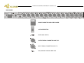
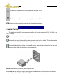
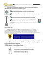
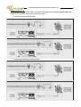
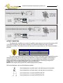
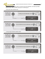
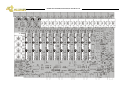
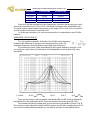
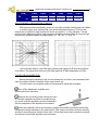
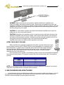
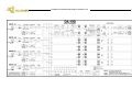
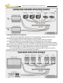
DA-410
DISTRIBUTION AMPLIFIER/ZONE MIXER/MIC SPLITTER
OWNERS MANUAL
EQUIPOS EUROPEOS ELECTRÓNICOS, S.A.L
Avda. de la Industria, 50. 28760 TRES CANTOS-MADRID (SPAIN).
34-1-804 32 65
34-1-804 43 58
[email protected]
www.altairaudio.com
DISTRIBUTION AMPLIFIER/ZONE MIXER/MIC SPLITTER DA-410.
2
1. INTRODUCTION................................................................................................................................................................................. 3
2. SWITCHES, CONTROLS, ADJUSTMENTS AND CONNECTORS................................................................................................... 4
FRONT PANEL .................................................................................................................................................................................. 4
REAR PANEL ..................................................................................................................................................................................... 5
3. WORKING PRECAUTIONS............................................................................................................................................................... 6
4. INSTALLATION .................................................................................................................................................................................. 6
UNPACKING .................................................................................................................................................................................... 6
MOUNTING...................................................................................................................................................................................... 6
CHANGING THE VOLTAGE ............................................................................................................................................................ 6
CHANGING THE FUSE .....................................................................................................................................................................7
CONNECTING TO THE MAINS....................................................................................................................................................... 8
INPUT CONNECTION ...................................................................................................................................................................... 8
UNBALANCED INPUT: ................................................................................................................................................................ 9
BALANCED INPUT: .....................................................................................................................................................................10
OUTPUT CONNECTION .................................................................................................................................................................10
UNBALANCED OUTPUT:.............................................................................................................................................................11
BALANCED OUTPUT: .................................................................................................................................................................12
GROUND LINK................................................................................................................................................................................12
5. OPERATION ......................................................................................................................................................................................13
TURN ON DELAY CIRCUIT.............................................................................................................................................................13
SIGNAL AND OVERLOAD INPUT INDICATOR.............................................................................................................................13
INPUT LEVEL CONTROL .................................................................................................................................................................13
SIGNAL AND OVERLOAD OUTPUT INDICATOR.........................................................................................................................13
OUTPUT LEVEL CONTROL .............................................................................................................................................................14
MONO SIGNAL SWITCH ...............................................................................................................................................................14
INPUT SIGNAL SELECTOR .............................................................................................................................................................14
MONITOR SIGNAL SELECTOR.......................................................................................................................................................14
MONITOR SIGNAL VU-METER......................................................................................................................................................15
MONITOR LEVEL CONTROL ..........................................................................................................................................................15
HEADPHONES OUTPUT ................................................................................................................................................................15
MINIATURE SPEAKERS ..................................................................................................................................................................15
MIC/LINE INPUT SIGNAL SELECTOR............................................................................................................................................15
OPERATING LEVEL CHART ............................................................................................................................................................16
6. OPTIONS...........................................................................................................................................................................................16
INPUT TRANSFORMER (IT-DA)......................................................................................................................................................16
OUTPUT TRANSFORMER (OT-DA) ...............................................................................................................................................16
EQUALISER CARD (TE-67) .............................................................................................................................................................16
SECURITY COVER (TP-1)................................................................................................................................................................. 17
KEY LOCKED SECURITY COVER (TS-1) ......................................................................................................................................... 17
7. SPECIAL OPERATIONS .................................................................................................................................................................... 17
INPUT TRANSFORMER (IT-DA)......................................................................................................................................................19
OUTPUT TRANSFORMER (OT-DA) ...............................................................................................................................................19
EQUALISER CARD.......................................................................................................................................................................... 20
EQUALIZER CARD CONFIGURATION ........................................................................................................................................21
GAIN CALCULATION............................................................................................................................................................21
FILTER FREQUENCY CALCULATION..................................................................................................................................... 22
BANDWIDTH CALCULATION (Q)......................................................................................................................................... 23
GAIN VARIATION ................................................................................................................................................................ 24
NON STANDARD CONFIGURATION EXAMPLES................................................................................................................ 25
PLACING AN EQUALIZER CARD ......................................................................................................................................... 25
LIFTING THE XLR INPUT GROUNDS ........................................................................................................................................... 26
8. BLOCK DIAGRAM AND HOW IT WORKS ................................................................................................................................... 26
9. REPAIR GUIDE ................................................................................................................................................................................. 28
10. APPLICATION EXAMPLES ............................................................................................................................................................ 29
DISTRIBUTION AMPLIFIER APPLICATION EXAMPLE................................................................................................................. 29
ZONE MIXER APPLICATION EXAMPLE ....................................................................................................................................... 30
MIC SPLITTER APPLICATION EXAMPLE.......................................................................................................................................31
11. TECHNICAL SPECIFICATIONS ....................................................................................................................................................... 32
12. WARRANTY.................................................................................................................................................................................... 33
DISTRIBUTION AMPLIFIER/ZONE MIXER/MIC SPLITTER DA-410.
3
1. INTRODUCTION
Congratulations on your purchase of the ALTAIR distribution amplifier/zone mixer/mic splitter
DA-410. Our dilated experience in the design and manufacture of effect processing equipment, had
led to us to carry out this distribution amplifier/zone mixer/mic splitter of great performances.
There is a lot the characteristics that make of the ALTAIR DA-410, one of the most highlighted of
the audio professional market, here enumerated some:
The ALTAIR DA-410 is a high performance distribution amplifier/zone mixer/mic splitter, compact,
only one rack 19" unit high, and is able to process two stereo input signals to obtain five stereo output
signals, both with independent level control.
Used as mixer (Zone Mixer), the unit could control five zones in stereo mode or ten in mono mode
(or any other combination) from the mix of its two stereo input signals.
As a audio distributor, allow obtaining up to ten mono output signals, or five in stereo mode for its
use in press rooms, recording units, audio production, broadcast, etc. Since it has two stereo inputs,
allow using the stereo input B as emergency input signal (reserve).
Individually selected MIC/LINE input preamplifiers allows microphone or line signals splitting to
additional mixers without quality and headroom degradation. Up to 4x8 or 1x10 active splitting is
possible.
One MONO switch by Zone allows to convert the output signals in order to adapt them to
monophonic equipment. If the input signals are monophonic, this switch is equally useful in order to
duplicate them to L, R (stereo).
The unit has a monitoring system or PFL with incorporate speakers, headphone output and
selectable Vu-meter allows analysing and calibrating the input signals and all the outputs. This stereo
monitoring system allows a simple and efficient control of audio continuity in moderate noisy
environments.
All the inputs and outputs are electronically balanced (XLR) and admit as option, input and output
transformers in order to improve the common mode rejection ratio or provide galvanic isolation.
Up to two parametric equaliser cards TE-F could be installed as option, in each one of the ten
outputs, permitting the appropriate tonal correction to each zone or speaker system.
Naturally, you want to use your distribution amplifier/zone mixer/mic splitter, but before
beginning is important that you read this manual. This manual will help you to install and use your new
distribution amplifier/zone mixer/mic splitter. It is very important that you read it carefully, mainly the
paragraphs marked as NOTE, PRECAUTION and DANGER, for your security.
Save the original packing, you can re-use it to transport the unit. NEVER SHIP THE DISTRIBUTION
AMPLIFIER/ZONE MIXER/MIC SPLITTER WITHOUT IT'S ORIGINAL PACKING.
4
DISTRIBUTION AMPLIFIER/ZONE MIXER/MIC SPLITTER DA-410.
2. SWITCHES, CONTROLS, ADJUSTMENTS AND CONNECTORS
These are the switches, controls, adjustments and connectors that you could find in your ALTAIR distribution amplifier/zone mixer/mic splitter. The
description and explanation of each one of them, you will find in the corresponding section.
FRONT PANEL
MINIATURE SPEAKERS.
MONITOR SIGNAL VU-METER.
SIGNAL AND OVERLOAD INDICATOR.
MONITOR LEVEL CONTROL.
INPUT LEVEL CONTROL.
MONITOR SIGNAL SELECTOR.
OUTPUT LEVEL CONTROL (CONCENTRIC).
HEADPHONES OUTPUT.
MONO SIGNAL SWITCH.
POWER SWITCH.
INPUT SIGNAL SELECTOR.
DISTRIBUTION AMPLIFIER/ZONE MIXER/MIC SPLITTER DA-410.
REAR PANEL
MAINS CONNECTOR AND FUSE HOLDER.
VOLTAGE SELECTOR.
EARTH LINK SWITCH.
OUTPUT SIGNAL CONNECTOR XLR-3-32.
INPUT SIGNAL CONNECTOR XLR-3-31.
MIC/LINE INPUT SIGNAL SELECTOR.
5
DISTRIBUTION AMPLIFIER/ZONE MIXER/MIC SPLITTER DA-410.
6
3. WORKING PRECAUTIONS
The manufacturer is not responsible of any damage occurred in the distribution amplifier/zone
mixer/mic splitter unit outside the limits of the warranty or those produced by not keeping in mind the
working precautions.
Mains voltage must be correct and the same as that setting on the rear of the unit voltage
switch. Damage caused by connection to improper AC voltage is not covered by any
warranty.
DANGER: Inside the distribution amplifier unit there are high voltages, doesn't open it.
The unit doesn't contain elements that could be repaired by the user. Whenever the
distribution amplifier unit is connected to the mains, contains elements with high voltages.
In order to disconnect the unit completely, you must disconnect it of the mains.
CAUTION: Protect the distribution amplifier from the rain and moisture. Ensure that no
objects or liquids enter it. If liquid is spilled into the unit, disconnect it from the mains and
consult a qualified service technician.
Don't place the unit close to heat sources.
4. INSTALLATION
UNPACKING
Before leaving from factory, each distribution amplifier was carefully inspected and tested.
Unpack and inspect the unit for any damage that may have occurred during shipment. If any
damage is found, doesn't connect the unit to the mains, notify the salesperson immediately,
because a qualified service technician must inspect the unit.
Save the original packing, you could use if you need to transport the unit. NEVER SHIP THE
DISTRIBUTION AMPLIFIER/ZONE MIXER/MIC SPLITTER WITHOUT IT'S ORIGINAL PACKING.
MOUNTING
It is always advisable to mount the unit in rack, either for mobile or fixed installations, for
protection, safety, aesthetics, etc.
The ALTAIR DA-410 is designed for standard 19" rack mounting, and occupy 1u high rack
space.
CHANGING THE VOLTAGE
The distribution amplifier/zone mixer/mic splitter unit is set to operate at 230V, 50-60Hz and
at 115V, 50-60Hz.
Make sure that the unit is disconnected of the mains.
Set up the voltage selector, placed at the unit rear panel, in the position that shows the
voltage, which you want to connect it.
DISTRIBUTION AMPLIFIER/ZONE MIXER/MIC SPLITTER DA-410.
Distribution amplifier/zone mixer/mic splitter set up to 230 V.
Distribution amplifier/zone mixer/mic splitter set up to 115 V.
Make sure that the fuse is the right one for the selected voltage:
FUSE (230V. 50-60 Hz) FUSE (115V. 50-60 Hz)
T0,5A.
T1A.
CHANGING THE FUSE
The distribution amplifier/zone mixer/mic splitter unit is set to operate at 230V, 50-60Hz or at
115V, 50-60Hz.
Make sure that the unit is disconnected from the mains.
In the unit rear panel, is placed the mains connector and the fuse holder. The box bellow this
mains connector is called fuse holder. Take out the fuse holder.
Upon extracting the fuse holder, the fuse will appear, take out it and change for the new one.
Insert the fuse holder into the mains connector again.
NOTE: The fuseholder provide a place for spare fuse.
CAUTION: Always make sure upon changing the fuse, that this is the adequate for the selected
mains voltage (T1A for 115V and T0,5A for 230V).
7
DISTRIBUTION AMPLIFIER/ZONE MIXER/MIC SPLITTER DA-410.
8
CONNECTING TO THE MAINS
The connection of the distribution amplifier/zone mixer/mic splitter power supply to the
mains takes place by a standard cord included in the box.
Make sure that the unit power switch is at 0 position (turned off).
Insert the female I.E.C. connector of the tripolar cable into the unit power supply
male connector, placed at the rear panel.
Insert the male connector of the tripolar cable into the mains plug.
Turn on the unit power switch. In that moment the MONITOR SIGNAL
SELECTOR LED indicator will light, indicating that the unit is turned on.
CAUTION: Make sure that the mains voltage is the correct as well as their fuse is the
adequate.
INPUT CONNECTION
The distribution amplifier input signals is carried out through four XLR-3-31 female
connectors, two per stereo channel. The input connections are balanced, with a nominal
impedance of 5 kΩ (2,5kΩ unbalanced) with the input set-up in line mode and 2 kΩ (1kΩ
unbalanced) with the input set-up in mic mode. The next list shows the input pins correspondence
as A.E.S recommendation practice:
INPUT CONNECTOR XLR-3-31
GND
PIN 1
PIN2
HOT (+)
COLD (-)
PIN3
The input connection depends on two factors, the first is the type of input signal balanced or
unbalanced, and the second the ground configuration of the sound source (floating or groundreferenced). The next pictures shows some of the different possibilities of connection, relying on the
type of input signal, balanced or unbalanced and according to the ground configuration of the
equipment (floating or ground-referenced).
NOTE: All the inputs and outputs of the unit accepts phantom power.
In the next diagrams, we use the following symbols:
Sound source with mains cord without ground connection.
Sound source with mains cord with ground connection.
Sound source with the EARTH-LINK OFF.
Sound source with the EARTH LINK ON.
DISTRIBUTION AMPLIFIER/ZONE MIXER/MIC SPLITTER DA-410.
UNBALANCED INPUT:
This type of connection will be used when the sound source doesn't provide balanced
output. When possible, employ the connection type 1.
1) Using twin-lead shielded cable:
2) Using single conductor shielded cable:
9
DISTRIBUTION AMPLIFIER/ZONE MIXER/MIC SPLITTER DA-410.
10
BALANCED INPUT:
OUTPUT CONNECTION
The distribution amplifier/zone mixer/mic splitter output signal is carried out through ten XLR3-32 male connectors, two per stereo channel. The outputs are balanced, with a nominal
impedance of 100 Ω. The next list shows the input pins correspondence as A.E.S recommendation
practice:
OUTPUT CONNECTOR XLR-3-32
GND
PIN 1
PIN2
HOT (+)
COLD (-)
PIN3
The output connection depends on two factors, the first is the type of input signal balanced or
unbalanced, and the second the ground configuration of the sound destination unit (floating or
ground-referenced). The next pictures shows some of the different possibilities of connection,
relying on the type of output signal, balanced or unbalanced and according to the ground
configuration of the equipment (floating or ground-referenced).
NOTE: All the outputs and inputs of the unit accepts phantom power.
In the next diagrams, we use the following symbols:
Sound destination unit with mains cord without ground connection.
Sound destination unit with mains cord with ground connection.
Sound destination unit with the EARTH-LINK OFF.
Sound destination unit with the EARTH LINK ON.
DISTRIBUTION AMPLIFIER/ZONE MIXER/MIC SPLITTER DA-410.
UNBALANCED OUTPUT:
This type of connection will be used when the sound destination unit doesn't provide a
balanced input. When possible, employ the connection type 1.
1) Using twin-lead shielded cable:
2) Using single conductor shielded cable:
11
DISTRIBUTION AMPLIFIER/ZONE MIXER/MIC SPLITTER DA-410.
12
BALANCED OUTPUT:
GROUND LINK
In some installations, it might be necessary to isolate the distribution amplifier/zone
mixer/mic splitter electric ground, from the system mains earth, in order to avoid ground loops that
could generate unwanted noises. For this reason, the unit provides an EARTH-LINK switch placed
at the rear panel in order to lift the mains earth from the unit.
MAINS EARTH LINKED WITH THE DISTRIBUION AMPLIFIER/
ZONE MIXER/MIC SPLITTER ELECTRIC GROUND.
MAINS EARTH LIFTED FROM THE DISTRIBUION AMPLIFIER/
ZONE MIXER/MIC SPLITTER ELECTRIC GROUND.
NOTE: For security reasons, the earth connection to the mains is linked with the unit chassis in both
cases.
CAUTION: Always operate the unit with the AC ground wire connected to the
electrical system ground. Precautions should be taken so that the means of
grounding of a piece of equipment is not defeated. For this circumstance, NEVER lift
the mains earth AC ground to avoid possible accidents. For your security, NEVER use
ground isolator adapters; instead it is recommended the EARTH -LINK switch.
DISTRIBUTION AMPLIFIER/ZONE MIXER/MIC SPLITTER DA-410.
13
5. OPERATION
The utility of the distribution amplifier/zone mixer/mic splitter is to process two input stereo
signals entering the unit to obtain five output stereo signals, both with independent level control.
Used as mixer (Zone Mixer), the unit could control five zones in stereo mode or ten in mono
mode (or any other combination) from the mix of its two stereo input signals.
As a audio distributor, allow obtaining up to ten mono output signals, or five in stereo mode for
its use in press rooms, recording units, audio production, broadcast, etc. Since it has two stereo
inputs, allow using the stereo input B as emergency input signal (reserve).
Individually selected MIC/LINE input preamplifiers allows microphone or line signals splitting to
additional mixers without quality and headroom degradation. Up to 4x8 or 1x10 active splitting is
possible.
NOTE: For simplicity in the next explanations, we are considering the unit as operating with stereo
inputs and outputs signals. Mono operation is similar. Exceptions are detailed separately when
necessary.
TURN ON DELAY CIRCUIT
The ALTAIR DA-410 incorporates a delay circuit, consisting of a relay, which protects the
output signal from switch-on transients. This delay takes two seconds, and in the meantime the
unit remains in mute.
SIGNAL AND OVERLOAD INPUT INDICATOR
The distribution amplifier/zone mixer/mic splitter incorporates a multipurpose signal
and overload circuit on each input. The indicator is made up of two LED's (one red and
one green) placed at the unit front panel.
This two point level circuit indicates the highest level reached inside the unit input circuits and
warns the operator about possible problems. When the level indicator lights green, the internal
level has reached -20 dBv. (signal present led). Should any internal level is near overload (+15 dBv)
the level indicator lights on red to warn the security limit has been surpassed. On that case the unit
has a 6 dB extra dynamic reserve or headroom. In order to correct this problem should lower the
level of that input or decreases the input signal (the output signal of the previous unit).
INPUT LEVEL CONTROL
Each stereo input (A & B) provides a gauged input level control between - ∞ and
+6 dB placed at the front panel. This input level control affect to the stereo signal level,
therefore this affect to the L & R inputs at the same time.
SIGNAL AND OVERLOAD OUTPUT INDICATOR
The unit incorporates a multipurpose signal and overload circuit on each output.
The indicator is made up of two LED's (one red and one green) placed at the unit front
panel.
DISTRIBUTION AMPLIFIER/ZONE MIXER/MIC SPLITTER DA-410.
14
This multipoint level circuit indicates the highest level reached inside the unit output circuits
and warns the operator about possible problems. When the level indicator lights green, the
internal level has reached -20 dBv. (signal present led). Should any internal level is near overload
(+15 dBv) the level indicator lights on red to warn the security limit has been surpassed. On that
case the unit has a 6 dB extra dynamic reserve or headroom. In order to correct this problem
should lower the level of that output or decreases the input signal.
OUTPUT LEVEL CONTROL
Each unit stereo output (1, 2, 3, 4 & 5) provides a gauged input level control
between - ∞ and +6 dB placed at the front panel. This output level control is rotary
and concentric. Internal knob is dedicated to control the Left (L) output level and the
external knob for Right (R) output level. When operating in mono mode, this
corresponds to outputs 1, 3, 5, 7, 9 and 2, 4, 6, 8 and 10 respectively.
MONO SIGNAL SWITCH
Each of the five sections incorporates a MONO switch that mix L and R incoming
signals routing it to the relevant outputs at the selected front panel output levels. When
this switch is not depressed, the L and R outputs are independent (stereo).
This switch allows adapting the stereo signals to monophonic equipment, and
equally duplicate the monophonic input signals for stereo equipments.
NOTE: If the input signal is monophonic, it's say, the input signal only are connected to L or R, upon
pressing the MONO switch, it will produce an attenuation of 6 dB in each one of the outputs. In
order to avoid this signal loss, it is advisable duplicate the inputs with an external bifurcation or
compensate it with the output gain controls.
INPUT SIGNAL SELECTOR
The input signal selector placed at the front panel, allow us select the input signal
that we will obtain at the output. When the A switch is depressed, we will obtain in the
stereo output (1, 2, 3, 4, or 5) the A stereo input signal. If we depressed the B switch, we
will obtain the B stereo input signal in the stereo output, and if we pressed the two at
the same time, we will obtain the sum of the two stereo input signals in L and R outputs
(the two outputs will have the same signal determined by the input level controls).
MONITOR SIGNAL SELECTOR
The monitor signal selector, placed at the front panel, allow us to
choose from any input or output stereo signals for monitoring purposes.
Selection is made sequentially by a momentary push button. This selector
allow us to monitor (either by means of the miniature speakers, or the
headphone output), all the outputs and inputs (A and B) and the sum of the
two stereo inputs (A+B). Upon turn on the unit, the monitor signal selector is placed automatically
in the output 1 position.
DISTRIBUTION AMPLIFIER/ZONE MIXER/MIC SPLITTER DA-410.
15
MONITOR SIGNAL VU-METER
The selected monitor signals drives a Stereo calibrated VU-METER ranging
from -12 dB, -6 dB, 0 dB, +3 dB and +6 dB. (0dB ref. 0 dBu). This 6 led VU-METER is
connected pre-monitor level and is intended for precise signal calibration. Refer to previous
paragraph about MONITOR SIGNAL SELECTOR.
MONITOR LEVEL CONTROL
The selected monitor stereo signal incorporates a stereo level control placed
at the front panel in order to control the headphones output level, or the miniature
speakers volume.
NOTE: In order to avoid breaks, never leave disregarded the monitor output level control. Avoid
prolonged saturation.
HEADPHONES OUTPUT
The headphones output are carried out by means of a stereo jack placed at the
front panel. This output can manage high impedance (100Ω - 600 Ω) standard stereo
headphones.
The signal that appears in the headphones output is the chosen in the monitor
signal selector and the level could be regulated with the monitor level control.
Upon introducing a stereo jack in the headphones output, automatically the miniature
speakers are disconnected.
MINIATURE SPEAKERS
The monitor listening of the selected signal, drives a pair of stereo
miniature speakers placed at the front panel. The volume control of these
miniature speakers is carried out by means of the monitor level control. Upon
introducing a stereo jack in the headphones output, automatically the miniature
speakers are disconnected.
This stereo monitoring system allows a simple and efficient control of audio continuity in
moderate noisy environments.
NOTE: In order to avoid breaks, never leave disregarded the monitor output level control. Avoiding
extend saturations. Avoid prolonged saturation.
MIC/LINE INPUT SIGNAL SELECTOR
The MIC/LINE input signal selector, placed at the rear panel, allows choosing
between line input signals or microphone input signals. The distribution amplifier/zone
mixer/mic splitter incorporates one mic/line input selector switch per input. Normal
position corresponds to line mode, and depressed to microphone signals inputs.
Nominal gain is 0 dB when line mode and +12 dB when configured as Mic.
Due to the reduced gain (+12 dB) in MIC mode, the DA-410 output signals must be externally
connected to preamplifiers or mixers into its MIC inputs.
16
DISTRIBUTION AMPLIFIER/ZONE MIXER/MIC SPLITTER DA-410.
The MIC mode is not intended as a microphone preamplifier. Instead, it accommodates or
adapts microphone impedances to the unit allowing perfect match between microphones and
long run cabling to external mixers.
This reduced gain, is optimised to use the unit as audio SPLITTER: If the input and output level
control is 0 dB or below, you can connect to the input either dynamic microphones, condenser
microphones or direct injection boxes without the necessity of setting-up the unit for each signal,
getting an autonomous operation.
This switch permits an extra gain of 12 dB for some applications. It is important to remember
that the input impedance becomes lower (2 kΩ) and upon connecting to old 600 Ω systems, an
insert loss of 2.3 dB will take place.
NOTE: All the inputs of the unit accept phantom power.
OPERATING LEVEL CHART
MODE
INPUT LEVEL
ADJUSTMENT
0 dB
MIC
+6 dB
0 dB
LINE
+6 dB
OUTPUT LEVEL
ADJUSTMENT
0 dB
+6 dB
0 dB
+6 dB
0 dB
+6 dB
0 dB
+6 dB
MAXIMUM INPUT
LEVEL
+ 9 dBu
+ 3 dBu
+ 3 dBu
-3 dBu
+ 22 dBu
+ 16 dBu
+ 16 dBu
+ 10 dBu
TOTAL GAIN
+12 dB
+18 dB
+18 dB
+24 dB
0 dB
+6 dB
+6 dB
+12 dB
6. OPTIONS
In this section will explain the different available options for the distribution amplifier/zone
mixer/mic splitter.
INPUT TRANSFORMER (IT-DA)
In order to improve the common mode rejection ratio and get a galvanic isolation with the
previous part of the audio system, it is available an input transformer.
Each XLR-3-31 input has an insert point for the input transformer; therefore, you could mount
four input transformers in the unit.
The provided transformers fulfil the isolation rule of 1.5 kV.
OUTPUT TRANSFORMER (OT-DA)
In order to get a galvanic isolation with the next part of the audio system, it is available an
output transformer.
Each XLR-3-32 output has an insert point for the output transformer; therefore, you could
mount ten output transformers in the unit.
The provided transformers fulfil the isolation rule of 2 kV.
EQUALISER CARD (TE-67)
In certain installations it is advisable the use of equalisation points in order to improve the
system frequency response. Inserting an equalisation directly in the distribution amplifier/zone
DISTRIBUTION AMPLIFIER/ZONE MIXER/MIC SPLITTER DA-410.
17
mixer/mic splitter is cheaper than utilise a graphic equaliser, and also avoids unwanted
manipulations.
The optional equaliser card provides a full parametric equalisation point. It means, you can
arbitrary choose and set-up the equalisation points parameters: gain, bandwidth and centre
frequency.
Two equalisation points per output (XLR-3-32) are available.
SECURITY COVER (TP-1)
In some installation, it could be necessary to tamper proof the front panel controls avoiding
unwanted or accidental manipulations. For this purpose, it is available as an option, a transparent
plastic security cover. The installation is very easy, by means of two screws provided.
KEY LOCKED SECURITY COVER (TS-1)
In some installations it is necessary isolate the distribution amplifier/zone mixer/mic splitter
controls more securely than with the plastic security cover. For this extra protection, it is available
an all-metallic and lockable security cover. This option cover fits into the four rack holes of the unit
and includes rear nut-bars allowing the installation as a stand-alone unit.
This cover prevents also from unauthorised extraction of the unit when rack mounted.
7. SPECIAL OPERATIONS
In order to set-up some of the distribution amplifier possibilities, the unit must be opened. Care
must be taken when removing the bottom cover as the line transformer is attached to it.
NOTE: This type of operations takes place with the unit open, for what it should be carried out by a
qualified technician.
DANGER: Before opening the unit, disconnect it from the mains. It is important to indicate that
although the unit is power out (with the power switch in 0 position), if it continues connected to the
mains there are different parts of the unit that are subjected to high voltage.
CAUTION: Protect the distribution amplifier from the rain and moisture, mainly if it is open. If liquid is
spilled into the unit, disconnect it from the mains and consult a qualified service technician.
The next picture shows the main PCB components layout of the unit to be used in the following
sections. Symmetry of the four input and ten output blocks makes ease the set-up, inspection, postservicing or installation of the available options.
Components naming starts in the upper left corner running to the opposite corner.
DISTRIBUTION AMPLIFIER/ZONE MIXER/MIC SPLITTER DA-410.
18
DISTRIBUTION AMPLIFIER/ZONE MIXER/MIC SPLITTER DA-410.
19
INPUT TRANSFORMER (IT-DA)
In order to improve the input common mode rejection ratio and for a galvanic isolation with
the previous part of the audio system, it is available an input transformer.
Each XLR-3-31 input has an insert point for the input transformer; therefore, you could mount
four input transformers in the unit. In the following table are shown the correspondence between
the inputs and their corresponding input transformers.
INPUT
INPUT AL
INPUT AR
INPUT BL
INPUT BR
TRANSFORMER POSITION
TR1
TR2
TR3
TR4
LINKS TO REMOVE
LK1 y LK2
LK3 y LK4
LK5 y LK6
LK7 y LK8
Before placing the transformer, you should remove the links corresponding to the input
transformer indicated in the following chart:
In the following picture is shown the placement of the input transformer TR1 corresponding to
the IN AL input. It is important to keep in mind the placement of the input transformer pins so that
they coincide with the main board (four to the left and three to the right).
Remove the links corresponding to the input transformer. In
this case LK1 and LK2.
Place the input transformer, keeping in mind the position of
their pins (four to the left and three to the right), and solder it to the
main board.
OUTPUT TRANSFORMER (OT-DA)
In order to make a galvanic isolation with the next part of the audio system, it is available an
output transformer.
Each XLR-3-32 output has an insert point for the output transformer; therefore, you could
mount ten output transformers in the unit. In the following table are shown the correspondence
between the outputs and their corresponding outputs transformers and the links that you must
remove to place the output transformer.
20
DISTRIBUTION AMPLIFIER/ZONE MIXER/MIC SPLITTER DA-410.
OUTPUT
OUT 1L (1)
OUT 1R (2)
OUT 2L (3)
OUT 2R (4)
OUT 3L (5)
OUT 3R (6)
OUT 4L (7)
OUT 4R (8)
OUT 5L (9)
OUT 5R (10)
TRANSFORMER POSITION
TR5
TR6
TR7
TR8
TR9
TR10
TR11
TR12
TR13
TR14
LINKS TO REMOVE
LK9 and LK10
LK11 and LK12
LK13 and LK14
LK15 and LK16
LK17 and LK18
LK19 and LK20
LK21 and LK22
LK23 and LK24
LK25 and LK26
LK27 and LK28
In the following picture is showing the placement of the output transformer TR5
corresponding to the OUT 1L (1) output. It is important to keep in mind the placement of the output
transformer pins so that they coincide with the main board (seven to the top and six to the bottom).
Remove the links corresponding to the output transformer. In this
case LK9 and LK10.
Place the output transformer, keeping in mind the
position of their pins (seven to the top and six to the
bottom), and solder it to the main board.
EQUALISER CARD
Two equaliser cards connectors are provided per output. Next table explains
the correspondence between the affected output and the labelled insert connector
as appears in the main distribution amplifier PCB.
OUT 1L
(1)
J1, J2
OUT 1R
(2)
J3, J4
EQUALISER CARD INSERT CONNECTORS
OUT 2L OUT 2R OUT 3L OUT 3R OUT 4L OUT 4R OUT 5L
(3)
(4)
(5)
(6)
(7)
(8)
(9)
J7, J8
J10, J11 J12, J13 J15, J16 J17, J18 J21, J22 J23, J24
OUT 5R
(10)
J26, J27
When the eq card is not installed, the signal path must be closed with a jumper.
Keep in mind this circumstance whenever you change, update or place for the first time an
equaliser card. Of course, in order to insert the equaliser card, you should remove the connector
jumper in which you want to place the equaliser card.
DISTRIBUTION AMPLIFIER/ZONE MIXER/MIC SPLITTER DA-410.
21
As seen in the main board component overlay, the jumper goes placed beside an indication.
It is important notice to install the jumper in the appropriate location, because placing it in the
wrong location could cause a short circuit in the power supply or additional malfunctions in the
unit.
EQUALIZER CARD CONFIGURATION
The next picture shows the component overlay of an equaliser card. As seen in the
picture, there are 6 resistors called RG+, RG-, RQ, RQ,' RF and RF'. This resistors define the gain
(RG+ or RG-), the bandwidth (RQ and RQ') and the centre frequency (RF and RF') of the
equalisation point:
Before adjusting an equaliser card, you should decide the gain, bandwidth and centre
frequency that you want to implement. Good results are obtained when using an external
parametric equaliser inserted in the signal path and the results are verified with a spectrum
analyser. Then, translate the obtained parameters to the next tables. A theoretical
approximation can also be used from the loudspeaker manufacturer graphs.
GAIN CALCULATION
There are two resistors in the equaliser card, labelled RG+ and RG- that configure the
equalisation point gain. For the gain you should only place a resistor, if you want positive
gains should place it in RG+, and if you want gains negatives (attenuation) should place it in
RG-.
The maximum gain of the equalisation point is 15 dB, since this resistor could not be
less than 2KΩ. If you want unitary gain, doesn't place any resistance.
The next table shows the resistors that you should use for gains between 1 and 15 dB,
in 1 dB steps. If you want an intermediate gain you are able to calculate an intermediate
value:
GAIN
1 dB
2 dB
3 dB
4 dB
5 dB
6 dB
7 dB
8 dB
9 dB
5% RESISTORS
82 KΩ
39 KΩ
24 KΩ
18 KΩ
13 KΩ
10 KΩ
8,2 KΩ
6,8 KΩ
5,6 KΩ
1% RESISTORS
82,5 KΩ
38,3 KΩ
24,3 KΩ
16,9 KΩ
13 KΩ
10 KΩ
8,06 KΩ
6,65 KΩ
5,62 KΩ
DISTRIBUTION AMPLIFIER/ZONE MIXER/MIC SPLITTER DA-410.
GAIN
10 dB
11 dB
12 dB
13 dB
14 dB
15 dB
5% RESISTORS
4,7 KΩ
3,9 KΩ
3,3 KΩ
3 KΩ
2,4 KΩ
2,2 KΩ
1% RESISTORS
4,64 KΩ
3,92 KΩ
3,32 KΩ
2,87 KΩ
2,49 KΩ
2,21 KΩ
For more accurate results, It is advisable the use of 1% film resistors.
You should be careful with the high gains adjustment (higher than 6 dB), since the
distribution amplifier/zone mixer/mic splitter dynamic decreases considerably.
FILTER FREQUENCY CALCULATION
There are two resistors in the equaliser card labelled RF and RF,' that configure the
centre frequency of the equalisation point. These two resistors should be equal: RF= RF.'
The next table shows the resistors that should use for the thirty frequencies ISO
standard. If you want an intermediate frequency, you are able to calculate an intermediate
value:
FREQUENCY
25 Hz
31,5 Hz
40 Hz
50 Hz
63 Hz
80 Hz
100 Hz
125 Hz
160 Hz
200 Hz
250 Hz
315 Hz
400 Hz
500 Hz
630 Hz
800 Hz
1 kHz
1,25 kHz
1,6 kHz
2 kHz
2,5 kHz
3,1 kHz
4 kHz
5 kHz
6,3 kHz
8 kHz
5% RESISTORS
2 MΩ
1,5 MΩ
1,2 MΩ
910 kΩ
750 kΩ
620 kΩ
470 kΩ
390 kΩ
300 kΩ
240 kΩ
200 kΩ
150 kΩ
120 kΩ
91 kΩ
75 kΩ
62 kΩ
47 kΩ
39 kΩ
30 kΩ
24 kΩ
20 kΩ
16 kΩ
12 kΩ
10 kΩ
7,5 kΩ
6,2 kΩ
1% RESISTORS
1,91 M Ω
1,54 M Ω
1,21 M Ω
953 kΩ
768 kΩ
604 kΩ
487 kΩ
383 kΩ
301 kΩ
243 KΩ
191 kΩ
154 kΩ
121 kΩ
95,3 kΩ
76,8 kΩ
60,4 kΩ
48,7 kΩ
38,3 kΩ
30,1 kΩ
24,3 kΩ
19,1 kΩ
15,4 kΩ
12,1 kΩ
9,76 kΩ
7,68 kΩ
6,04 kΩ
22
23
DISTRIBUTION AMPLIFIER/ZONE MIXER/MIC SPLITTER DA-410.
FREQUENCY
10 kHz
12,5 kHz
16 kHz
20 kHz
5% RESISTORS
4,7 kΩ
3,9 kΩ
3 kΩ
2,4 kΩ
1% RESISTORS
4,87 kΩ
3,83 kΩ
3,01 kΩ
2,43 kΩ
If you don't find the resistances for low frequencies, since they are very big, you could
change the capacitors C2 and C3 to 33 NF, and divide the resistor value of the table by 10.
This could only be made between frequencies in the range of 25 Hz and 2 kHz, since the RF
and RF' resistors could never be less than 2 kΩ.
As in the gain calculation, for more accurate results, It is advisable the use of 1% film
resistors.
BANDWIDTH CALCULATION (Q)
The Q is the filter bandwidth. So that the Q is the filter centre frequency
divided by the difference of the higher and lower frequency, which the
amplitude response is three dB down from the filter centre frequency.
The next picture shows a filter with different Q at the same frequency and gain. How
you could see a high value of Q indicates a small bandwidth and a low value of Q a big
bandwidth.
F = 1 kHz.
Q=0,5
Q=1,0
Q=2,5
Q=5
There are two resistors in the equaliser card labelled RQ and RQ,' those configure the
bandwidth (Q) of the equalisation point. These two resistors should be equal RQ = RQ.'
The next table shows the resistor that you should use for bandwidths (Q) from 0.1 to 10.
The maximum value allowed for the RQ and RQ' resistors are 150 kΩ corresponding to Q=15.
If you want an intermediate bandwidth, you are able to calculate an intermediate value:
24
DISTRIBUTION AMPLIFIER/ZONE MIXER/MIC SPLITTER DA-410.
Q
5% RESISTORS
1% RESISTORS
Q
5% RESISTORS
1% RESISTORS
Q
5% RESISTORS
1% RESISTORS
Q
5% RESISTORS
1% RESISTORS
Q
5% RESISTORS
1% RESISTORS
Q
5% RESISTORS
1% RESISTORS
Q
5% RESISTORS
1% RESISTORS
Q
5% RESISTORS
1% RESISTORS
Q
5% RESISTORS
1% RESISTORS
Q
5% RESISTORS
1% RESISTORS
0,1
1 KΩ
1KΩ
1,1
11KΩ
11,0KΩ
2,1
-21,0KΩ
3,1
-30,9KΩ
4,1
-41,2KΩ
5,1
51KΩ
51,1KΩ
6,1
--7,1
-71,5KΩ
8,1
-80,6KΩ
9,1
91KΩ
91,0KΩ
0,2
2KΩ
2KΩ
1,2
12KΩ
12,1KΩ
2,2
22KΩ
22,1KΩ
3,2
-32,4KΩ
4,2
-42,2KΩ
5,2
-52,3KΩ
6,2
62KΩ
61,9KΩ
7,2
--8,2
82KΩ
-9,2
---
0,3
3KΩ
3,01KΩ
1,3
13KΩ
13,0KΩ
2,3
-23,2KΩ
3,3
33KΩ
33,2KΩ
4,3
43KΩ
43,2KΩ
5,3
--6,3
-63,4KΩ
7,3
-73,2KΩ
8,3
-82,5KΩ
9,3
-93,1KΩ
0,4
3,9KΩ
4,02KΩ
1,4
-14,0KΩ
2,4
24KΩ
24,3KΩ
3,4
-34,0KΩ
4,4
-44,2KΩ
5,4
-53,6KΩ
6,4
--7,4
--8,4
--9,4
---
0,5
5,1KΩ
4,99KΩ
1,5
15KΩ
15,0KΩ
2,5
-24,9KΩ
3,5
-34,8KΩ
4,5
-45,3KΩ
5,5
-54,9KΩ
6,5
-64,9KΩ
7,5
75KΩ
75KΩ
8,5
-84,5KΩ
9,5
-95,3KΩ
0,6
6,2KΩ
6,04KΩ
1,6
16KΩ
16,2KΩ
2,6
-26,1KΩ
3,6
36KΩ
35,7KΩ
4,6
-46,4KΩ
5,6
56KΩ
56,2KΩ
6,6
--7,6
--8,6
--9,6
---
0,7
6,8KΩ
6,98KΩ
1,7
-16,9KΩ
2,7
27KΩ
26,7KΩ
3,7
-37,4KΩ
4,7
47KΩ
-5,7
--6,7
-66,5KΩ
7,7
-76,8KΩ
8,7
-86,6KΩ
9,7
---
0,8
8,2KΩ
8,06KΩ
1,8
18KΩ
18,2KΩ
2,8
-28,0KΩ
3,8
-38,3KΩ
4,8
-47,5KΩ
5,8
-57,6KΩ
6,8
68KΩ
68,1KΩ
7,8
--8,8
--9,8
-97,6KΩ
0,9
9,1KΩ
9,09KΩ
1,9
-19,1KΩ
2,9
-28,7KΩ
3,9
39KΩ
39,2KΩ
4,9
-48,7KΩ
5,9
-59,0KΩ
6,9
--7,9
-78,7KΩ
8,9
-88,7KΩ
9,9
---
1
10KΩ
10KΩ
2
20KΩ
20,0KΩ
3
30KΩ
30,1KΩ
4
-40,2KΩ
5
-49,9KΩ
6
-60,4KΩ
7
-69,8KΩ
8
--9
--10
100KΩ
100KΩ
As seen in the table, there are Q values for which don't exist available commercial
resistors. In that case you should approach to the nearest Q.
As in the others cases, for more accurate results, it is always advisable that use 1%
resistors.
GAIN VARIATION
Apart from the gain, frequency and Q variations, you could vary the total output gain in
which it is insert the equalisation point. This one could carry out varying the R1 resistor of the
equaliser card.
The formula that gives us the gain is showed in the picture, the gain
in dB and the resistor in Ω. The factory value for R1 is 10 kΩ, giving a gain of
0 dB. For example, for a gain of 6 dB, the resistor R1 would be of 5.1 kΩ 5%
or 4.99 kΩ 1%, and for a gain of - 6 dB, the resistor R1 would be 20 kΩ 5%
or 20 kΩ 1%. You should use values lower than 2 kΩ for this resistor.
You should be careful in the adjustment of high gains (great of 6 dB), since the
distribution amplifier/zone mixer/mic splitter dynamic diminishes considerably.
The next table shows the value of R1 resistor for different gains:
25
DISTRIBUTION AMPLIFIER/ZONE MIXER/MIC SPLITTER DA-410.
GAIN
R1
5%
1%
+6 dBv
+4 dBv
+2 dBv
-2 dBv
-4 dBv
-6 dBv
5,1 KΩ
4,99 KΩ
6,2 KΩ
6,34 KΩ
7,5 KΩ
7,87 KΩ
12 KΩ
12,4 KΩ
16 KΩ
15,8 KΩ
20 KΩ
20 KΩ
NON STANDARD CONFIGURATION EXAMPLES
With the parametric equalisation point, you can also simulate shelving and notch filters.
In order to carry out a shelving filter, you should select the frequency 35 Hz for low
frequencies or 16 kHz for high frequencies and a very small Q - 0.4 for example. The left
picture shows different equaliser card examples simulating shelving filters for low and high
frequencies, at different gains and attenuations +5, +10, +15, -5, -10 & -15:
You could also make a notch filter type, selecting the highest Q (15) that the equaliser
card allows. The right picture shows a notch filter type with 15 dB of attenuation at 1 kHz:
PLACING AN EQUALIZER CARD
Before placing the equaliser card you should adjust it, for this it is recommended that
read the previous sections carefully, if you haven't done yet.
In order to place an equaliser card in the main board, follow the next steps:
Turn off the distribution amplifier and
disconnect it from the mains.
Remove the connector jumper where you want
to insert the equaliser card (the connectors where
you could insert the equaliser card are indicated in
the first paragraph of the equaliser card section).
Insert the equaliser card in the connector, guiding the printed circuit board toward the
component overlay indication in the main board. Take care to insert the connector carefully,
and don't move it forward, behind, left or right. All the main board male connector contacts
should join in the female equaliser card connector.
DISTRIBUTION AMPLIFIER/ZONE MIXER/MIC SPLITTER DA-410.
26
WARNING: Before carrying out any operation inside the distribution amplifier/zone
mixer/mic splitter, disconnect it from the mains. Upon being connected to the mains, the
distribution amplifier/zone mixer/mic splitter contains elements with high voltages, and if for
negligence you touch one of those parts could cause a short circuit through your body with
the rising danger for your health.
CAUTION: Do not insert an equaliser card with the distribution amplifier/zone mixer/mic
splitter turn on, this could cause its break.
CAUTION: After placing the equaliser card in a insert connector, and before turning on the
distribution amplifier/zone mixer/mic splitter, make sure that the equaliser card is placed
correctly in the main board connector, and that any of the connector contacts is out of it. A
wrong placement of the equaliser card could cause that the distribution
amplifier/zone mixer/mic splitter and the equaliser card break.
LIFTING THE XLR INPUT GROUNDS
When carried out a connection of balanced input with a ground-referenced sound
source (refer the section INPUT CONNECTION for more information), it is necessary to lift
the input ground. In order to don't modify the cable, the DA-410 has jumpers that open
the input grounds. With the jumper placed, the ground is close, and with the jumper
removed, the ground is lifted (in order to don't lose the jumper, it could be placed
attached over one of the two pins).
Each input has its own jumper. In the following chart is shown the correspondence between
the inputs and their jumpers. This jumper is factory set to the closed position (pin 1 connected to
ground).
INPUT
IN AL
IN AR
IN BL
IN BR
JUMPER POSITION
JP1
JP2
JP3
JP4
NOTE: It is important to know that the input ground could be lifted only in balanced connections,
otherwise, it's possible that the unit doesn't work correctly.
8. BLOCK DIAGRAM AND HOW IT WORKS
In the following shows the distribution amplifier/zone mixer/mic splitter block diagram, with all
the options that we could insert. It is draw the channels 1L (1) and 1R (2) only, since the others are
identical, they are simplified (only the options are shown)
DISTRIBUTION AMPLIFIER/ZONE MIXER/MIC SPLITTER DA-410.
27
DISTRIBUTION AMPLIFIER/ZONE MIXER/MIC SPLITTER DA-410.
28
In the input stage, each one of the inputs has a jumper that lifts the input XLR ground. Next, the
signal crosses the input transformer (if the option is placed) and the switch LINE/MIC that allows to
choose the input gain (in line mode won't have gain, and in mic mode will have 12 dBu of gain).
Following the signal is electronically unbalanced and crosses the input level control. Note that the
input level detector reference signal is measured in two points. It's measured before and after the
input level control, in order to know if the input signal is overloaded before the DA-410 input or in the
input amplifier.
In the output stage, the signal crosses the input signal selector, that allow us to choose the input
signals A, B or both, for later carry out the input signals summing. Next it is the MONO switch that
adds the L and R output signals, and the output level control. Following the signal crosses the two
equaliser cards (if the options are placed), the electronic balanced output and the output transformer
(it the option is placed) and the output XLR connector. The output level detector reference signal is
measured in three points: A, B and C, the point A is located just after the input signal sum, the point B
after the output amplifier and the C point after the equaliser cards.
The monitor signal selector, take the output signal, just before the electronic balanced output,
allowing to listen the signal just in the output (either for the speakers or headphones), giving us a very
real signal reading. As seen in the block diagram, once selected the monitor signal, it crosses a level
control and a 10 dB amplifier driving the speakers (we could see in the block diagram, that when we
introduce a headphones jack, the signal in the speakers is muted).
9. REPAIR GUIDE
For service purposes, the unit must be open by removing the eight screws on the top cover.
NOTE: This type of operations takes place with the unit open, for what it should be carried out by a
qualified technician.
DANGER: Before opening the unit, disconnect it from the mains. It is important to indicate that
although the unit is power out (with the power switch in 0 position), if it continues connected to the
mains there are different parts of the unit that are subjected to high voltage.
CAUTION: Protect the distribution amplifier from the rain and moisture, mainly if it is open. If liquid is
spilled into the unit, disconnect it from the mains and consult a qualified service technician.
Keep in mind that all the outputs are symmetrical, so when the section is identified, you could
interchange components, except for the circuits that are common to all the outputs as could be the
power supply, or the monitor signal selector.
We recommend a meticulous visual exam before beginning to change anything in the unit:
burnt resistors, potentiometers with a broken trace, etc. This exam many times gives us the key for the
problem, saving time and unnecessary efforts.
Keep in mind when removing an element of the main board, that it is double layer printed
circuit, and the components PADs goes joined from one layer to the other through a metal tube (VIA).
For that reason, avoid excessive overheating and strength that could pulled out the VIA. This is
important mainly in components having many pins (integrated circuits, connectors, etc.), for which it is
recommended to use a good desoldering station.
DISTRIBUTION AMPLIFIER/ZONE MIXER/MIC SPLITTER DA-410.
29
Next paragraphs details some of the most frequent fixes as a guide to the qualified technical
service helping to repair the unit:
If a fuse break due to a mains transient or when the unit has been connected accidentally to 380
line voltages, replace it with the same ratings as described before. If it breaks again, check the
overvoltage protections placed on the voltage selector. If broken, substitute them by an equivalent
part (130 volts VARISTOR).
If the power supply fails, the unit will remain in MUTE mode. In this case it is necessary to check
the rectifier bridge (D50), the filter capacitors (C99, C100, C101, C103 and C115) and the regulators
(U25, U29 and U32). Keep in mind that if the unit has been turned on, the regulators heatsinks could
be hot, with the rising danger of burns.
Upon changing the damaged element, it is necessary to ascertain that no element is
overheating in the main board, since this can be origin of the problem.
The potentiometers have a limited live span; they could become dirty and produce noise upon
moving them. It is important that you don't use sprays cleaners over the potentiometers, since they
can become damaged shortly. We recommended cleaning it by compressed air only.
In order to change a potentiometer, the unit must be opened. Care must be taken when
removing the bottom cover as the line transformer is attached to it.
To remove the front panel, extract all five visible screws. The sub-panel behind the front panel is
joined to the chassis by four screws located in the chassis sides and by the potentiometers. Special
care must be taken when re-install the front panel because some delicate parts as the LED lamps
must be introduced in small panel holes and it is a not easy operation.
Normally the signal reductions in the distribution amplifier/zone mixer/mic splitter are produced
by three causes: the LEVEL potentiometers, the unbalanced circuit and the electronic balanced one. In
the unbalanced and electronic balanced circuits, a signal reduction around 6 dB reveals that one
halves of the circuit has any trouble. The LEVEL potentiometers failures gives also sudden random
signal reductions as well as swinging signals.
10. APPLICATION EXAMPLES
In the following schematic drawings are represented three of the more common applications of
the unit:
Distribution amplifier: For signal buffering and remote distribution.
Zone mixer: Dedicated mixing to separate ambient locations.
Active splitter: Microphone/Line splitting for optimal, noise free large sound systems.
DISTRIBUTION AMPLIFIER APPLICATION EXAMPLE
In the distribution amplifier example application, we have supposed a conference session
that should be transmitted to several televisions and radio stations.
A mixing console (two for system redundancy), processes all the microphone and line
signals involved in the session. The output console output and the redundant system if needed,
drives the DA-410 inputs. In this case, we configure the inputs in LINE mode operation. The
distribution amplifier then buffers the selected signal A or B to each one of the televisions and/or
radio stations separately. MONO switch allows us to convert the stereo signal provided in order to
adapt them to monophonic equipment.
In case of the main system failure, simple selection of B redundant system restores signal
transmission quickly.
The use of input (IT-DA) and output (OT-DA) transformers is recommended in order to provide
a galvanic isolation with the television and/or radio systems.
DISTRIBUTION AMPLIFIER/ZONE MIXER/MIC SPLITTER DA-410.
30
ZONE MIXER APPLICATION EXAMPLE
In the zone mixer application example, we have supposed a standard hotel set-up with
different sound zones, with two sound programs and several levels.
The input signals to the DA-410 come from a mixer console (in order to control the
microphones for example) and a cassette desk (or a CD) both working in stereo mode.
With the DA-410 outputs will feed the amplifiers of the different zones, controlling the signal
level to each zone and enabling to choose one of the two stereo programs in each zone by means
of the input signal selector. The zones could be mono or stereo since the MONO switch allows us
to convert the stereo signals in order to adapt them to monophonic equipments.
The use of equaliser cards (TE-67) for each zone is recommended, in order to correct the
frequency response of each room and personalise the system.
DISTRIBUTION AMPLIFIER/ZONE MIXER/MIC SPLITTER DA-410.
31
MIC SPLITTER APPLICATION EXAMPLE
In the mic splitter example application, we have supposed a live show, in which we should
give signal to a recording truck. For explanation simplicity, we supposed a reduced set-up about
four microphones and a DA-410 only. Normal set-ups will need 32 or more microphone inputs
corresponding to 8 or more DA-410 units.
The F.O.H. (Front of house) console is connected directly to the stage box, to give phantom
powering to the microphones requiring it. The other output of the stage box (both are paralleled) is
connected to the DA-410 inputs. In this configuration the inputs are configured in MIC mode
operation, regardless of the input signal level. See previous related paragraphs. DA-410 outputs
drives separately the Monitor and remote recording consoles avoiding ground loops, interference,
and accidental signal drop-outs conflicts.
The use of input (IT-DA) and output (OT-DA) transformers is recommended in order to provide
a galvanic isolation within all three consoles assuring also an increasing performance in
interference rejection on large cable runs normally found in these set-ups.
DISTRIBUTION AMPLIFIER/ZONE MIXER/MIC SPLITTER DA-410.
11. TECHNICAL SPECIFICATIONS
TECHNICAL SPECIFICATIONS
NUMBER OF INPUTS:
INPUT IMPEDANCE:
INPUT LEVEL:
INPUT GAIN/ATTENUATION:
NOMINAL GAIN:
NUMBER OF OUTPUTS:
OUTPUT IMPEDANCE:
OUTPUT LEVEL:
OUTPUT GAIN/ATTENUATION:
C.M.R.R.:
NOISE:
FREQUENCY RESPONSE:
CHANNEL SEPARATION:
INDICATORS:
MONITORING:
DISTORTION:
MAINS SUPPLY:
POWER REQUIREMENT:
DIMENSIONS:
OPTIONS:
• 2 stereo (XLR-3-31).
2 kΩ/5 kΩ (MIC/LINE). Electronically balanced.
• 0 dBu nominal.
• +9 dBu maximum Mic input.
• +22 dBu maximum line input.
• +6/-∞ dB. Level control via calibrated rotary potentiometer.
• 0 dB/+12 dB. Line/Mic input selection.
• 5 stereo or 10 mono (XLR-3-32).
• 100Ω. Electronically balanced.
• 0 dBu nominal / +26 dBu maximum (XLR-3-32).
• +6/-∞ dB. Level control via calibrated rotary potentiometer.
• Greater than 55 dB (20 Hz - 20 kHz).
• Less than -100 dBu at any output, 20 Hz to 20 kHz,
unweighted.
• E.I.N.: 111 dBu. Mic inputs, 200 Ω source impedance.
• 10 Hz to 50 kHz (+0, -0.5 dB).
• Greater than 90 dB @ 1kHz, 67 dB (20 Hz - 20 kHz).
• CLIP (+15 dBu) red LED (two per stereo input and output).
• SIGNAL (-20 dBu) green LED (two per stereo input and
output).
• 5 LED's stereo Vu-meter, switchable between inputs and
outputs.
• Vu-meter visualisation selector (8 LED's).
• Headphones output, Jack 1/4".
• Built-in stereo micro-speakers (maximum SPL 82 dBA).
• Less than 0.01% at 0 dBu (20 Hz - 20 kHz).
• User selectable 115 and 230 VAC ±12%, 50-60 Hz.
• 30 V.A.
• 483x44x245 mm. (19" x 1u).
• Input and output transformers.
• Equaliser cards (2 per output).
• Plastic or metal (key protected) security cover.
•
NOTE: Technical specifications subject to variation without previous notice.
32
DISTRIBUTION AMPLIFIER/ZONE MIXER/MIC SPLITTER DA-410.
33
12. WARRANTY
This unit is warranted by Equipos Europeos Electrónicos to the original user, against flaws in the
manufacturing and in the materials, for a period of one year, starting from the date of sale.
Flaws due to wrong use of the unit, internal modifications or accidents, are not covered by this
warranty.
There is no other warranty expressed or implicit.
Any faulty unit must be sent, to the dealer or the manufacturer. The serial number of the unit
must be included with any request for the technical service.
Equipos Europeos Electrónicos reserves the right to modify the prices or the technical
specifications without notice.
SERIAL NUMBER
...................................................
EQUIPOS EUROPEOS ELECTRÓNICOS, S.A.L
Avda. de la Industria, 50. 28760 TRES CANTOS-MADRID (SPAIN).
34-91-804 32 65
34-91-804 43 58
[email protected]
www.altairaudio.com
European Union
Waste Electronics Information
Unión Europea
Información sobre residuos electrónicos
Waste from Electrical and Electronic Equipment (WEEE) directive
The WEEE logo signifies specific recycling programs and procedures for
electronic products in countries of the European Union. We encourage the
recycling of our products. If you have further questions about recycling, contact
your local sales office.
Directiva sobre Residuos de Aparatos Eléctricos y Electrónicos (RAEE)
El logotipo de la Directiva RAEE se refiere a los programas y procedimientos
específicos de reciclaje para aparatos electrónicos de países de la Unión
Europea. Recomendamos el reciclaje de nuestros productos. Si tiene alguna
consulta, póngase en contacto con su Distribuidor.
Information based on European Union WEEE Directive 2002/96/EC
Información basada en la Directiva de la unión europea RAEE 2002/96/EC y el Real Decreto 208/2005
AUDIO ELECTRONICS DESIGN
EQUIPOS EUROPEOS ELECTRÓNICOS, S.A.L
Avda. de la Industria, 50. 28760 TRES CANTOS-MADRID (SPAIN).
34-91-761 65 80
34-91-804 43 58
www.altairaudio.com
[email protected]


![installation & directions for use installation & mode d`emploi [ en ] [ fr ]](http://vs1.manualzilla.com/store/data/006516414_1-826c39eefa343060f035675bc430e123-150x150.png)