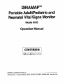
1
DINAMAPm
Portable Adult/Pediatric and
Neonatal Vital Signs Monitor
Model 8100
Operation Manual
a
company
DINAMAPTM is a trademark of Critikon, Inc.
CRITIKON, INC. 4110 George Road Tampa, Florida U.S.A. 33634
(813)887-2000 Telex 494 3183
CRITIKON, INC.
CONTENTS
List of Effective Pages.. .................................................................ii
List of Illustrations.. .......................................................................
vi
List of Tables.. ..............................................................................
vi
Frontispiece.. ..............................................................................
SECTION 1.
INTRODUCTION
General.. .....................................................................................
Manual Purpose.. .........................................................................
Manual Effectivity.. .......................................................................
Reissues.. .............................................................................
Change Information Sheets.. ..................................................
Errors, Omissions, Incorrect Data.. ...........................................
Related Publications.. ..................................................................
Instruction Labels ....................................................................
Service Manual.. .....................................................................
SECTION 2.
...
VIII
.l
.l
.l
.l
.1
.l
.2
2
.2
PRODUCT DESCRIPTION
Overview.. ....................................................................................3
Unique Operating Features.. ......................................................... 3
4
Accessories.. ................................................................................
Standard Accessories.. ...........................................................4
4
Optional Accessories ..............................................................
SECTION 3.
PHYSICAL DESCRIPTION
Performance Specifications ........................................................... 7
Technical Specifications.. .............................................................. 8
8
Mechanical .............................................................................
8
Electrical ................................................................................
9
Environmental ........................................................................
Controls, Indicators, Connectors .................................................. 10
...
III
DINAMAPTM PORTABLE ADULT/PEDIATRIC and NEONATAL VITAL SIGNS MONITOR OPERATION MANUAL
CONTENTS
SECTION 4. FUNCTIONAL DESCRIPTION
Continued
Determination Sequence
.
Maximum-Minimum Ranges
Basic Operating Cycle
Operating Modes
Manual Mode
AutoMode . . . . . . . . . . . . . . . . . . . . . . . . .
Neonatal or Adult/Pediatric Monitoring
Systolic Search
Undetermined Systolic and Diastolic Pressures
SECTION 5.
.
.
.
15
17
17
18
18
18
19
19
19
INSTALLATION AND OPERATION
Unpacking ................................
Content Checklist .........................
Missing Items ..............................
Indications and Contraindications ...............
Installation and Initial Setup ...................
Electrical and Hose Connections
.............
Operating Warnings, Precautions, and Notes
......
Operating Procedures ........................
Power-On Procedure .........................
Set Alarm Limits Procedure ....................
ManualMode ..............................
AutoMode ................................
Alarm Indications and Interpretation .............
Patient Alarms .............................
System Alarms .............................
Troubleshooting
............................
Determination Unsuccessful Alarm (899)
.......
Power-On Self Check (888)
..................
Excess Time at One Pressure Alarm (855)
.......
Excess Determination Time Alarm (844) .........
Excess Inflation Time Alarm (833) .............
Microcomputer Alarm (Blank, 900 to 999) .......
Excess Pressure Alarm (800)
................
Monitor Will Not Power-ON
..................
Monitor Displays Extremely High Readings ......
Monitor Displays Extremely Low Readings ......
Patient Alarms Activate After Every Determination
21
21
21
21
22
22
24
28
28
27
28
28
29
29
29
33
33
33
33
34
34
34
35
35
35
35
35
CONTENTS
SECTION 8.
MAINTENANCE AND CALIBRATION
Continued
Maintenance
._.....__., __..__....
Cleaning ,_.., ., . . ..__...._...._...._ . . .
Storage
.., . ..__. ._...__.., . ..__..
Battery Charging
Battery Removal and Replacement
Changing Fuses . .
.._...._...._..........
Replacement of Line Power Fuses ,
Replacement of Battery Fuse
Calibration
Blood Pressure Calibration Check
Cuff and Hose Leak Check
Performing a Cuff and Hose Pneumatic Leak Check
37
37
37
37
36
41
41
44
44
44
46
46
DINAMAPTM PORTABLE ADULT/PEDIATRIC and NEONATAL VITAL SIGNS MONITOR OPERATION MANUAL
LIST OF ILLUSTRATIONS
LIST OF TABLES
Figure No.
Title
Page
Frontispiece
VIII
3-1
3-2
Front Panel Controls and Indicators ...........
Rear Panel Controls and Indicators ............
10
14
4-1
4-2
4-3
Determination Sequence ..............
Basic Operating Cycle ................
Low Amplitude Waveform Diagram
......
16
17
19
5-l
Recommended Cuff Placement
23
6-1
6-2
6-3
6-4
6-5
6-6
6-7
6-8
6-9
6-10
Loosen the Battery Door Hold-down Screws
Remove Battery Door
Remove Battery
Remove Battery Cable Connectors
Open AC Line Fuse Compartment
Remove Fuse Holder
Remove Fuse from Fuse Holder
Replace AC Line Fuse and Fuse Holder
Calibration Check Setup
Cuff and Hose Leak Setup
39
39
40
40
42
42
43
43
44
47
Table No.
Title
Page
3-1
3-2
Front Panel Controls and Indicators
Rear Panel Controls and Indicators
10
14
4-I
Maximum and Minimum Detectable Pressures
17
5-l
5-2
5-3
Cuff-to-Hose Compatibility
Default Alarm Limits
System Alarms Summary
6-1
6-2
Battery Charging Characteristics
Calibration Check Pressure Levels
23
26
31132
38
46
CRITIKON, INC.
SECTION 1. INTRODUCTION
SECTION 1. INTRODUCTION
GENERAL
The DINAMAPTM Portable Vital Signs Monitor 8100 is designed to
noninvasively and automatically measure systolic and diastolic pressure,
mean arterial pressure (MAP), and pulse rate for neonatal or adult/pediatric
patients. Results are displayed on large, easy-to-read digital displays. The
monitor will operate on AC line voltage or on its internal battery. The monitor
will cycle automatically at operator programmed intervals between one and
ninety minutes. Results of the last determination will remain displayed (up to
ninety minutes) until another determination is completed.
The DINAMAPT” Portable Monitor Model 8100 is effective and versatile. It
continues to monitor during most clinical crises when other indirect
measurement methods may fail. The monitor can be used in any hospital
area where critical care is administered, for example, emergency room,
operating room, recovery room, intensive care unit, cardiac care unit, renal
dialysis unit, burn unit, etc.
MANUAL PURPOSE
This Operation Manual was prepared for the operator of the DINAMAPTM
Portable Monitor Model 8100. This manual contains installation and
operation instructions, device applications, limitations, and routine
performance verification procedures. To achieve satisfactory results, the
operator must read this manual thoroughly before attempting to use the
Monitor.
MANUAL
EFFECTIVITY
Reissues
Changes to this manual, either in response to user input or to continuing
product improvements, are accomplished through reissue.
Change Information Sheets
Changes occurring between reissues are addressed through Change
Information Sheets and replacement pages. If a Change Information Sheet
does not accompany this manual, it is correct as printed.
Errors, Omissions, Incorrect Data
If, in the normal use of this manual, errors, omissibns, or incorrect data, are
noted please complete the Publications Change Request Form located in
the back ot this manual. Submit the form to:
Critikon, Inc.
Marketing Services
4110 George Road
Tampa, Florida 33634
DINAMAP’” PORTABLE ADULT/PEDIATRIC and NEONATAL VITAL SIGNS MONITOR OPERATION MANUAL
RELATED
PUBLICATIONS
Instruction Labels
Two permanently affixed labels, one on each side of the monitor, contain
condensed operation and alarm code information.
Service Manual
The DINAMAP’” Portable Monitor Model 8100 Service Manual (776-370)
contains service and repair parts information directed to qualified
service personnel.
WARNING
To avoid personal injury, the user should not perform any
servicing unless qualified to do so.
CRITIKON, INC.
SECTION 2. PRODUCT DESCRIPTION
SECTION 2. PRODUCT DESCRIPTION
OVERVIEW
UNIQUE OPERATING
FEATURES
The DINAMAP’” Portable Monitor, Model 8100, is designed to provide
operator convenience and reliability when monitoring vital signs.
Features that enhance the DINAMAP’” Monitor’s operation follow.
FULLY AUTOMATIC PATIENT SELECTION AND MONITORING
Senses cuff size and switches automatically from adult/pediatric
monitoring to neonatal monitoring or vice versa. Can be
programmed to make determinations automatically at various
intervals between 1 and 90 minutes.
NONINVASIVE AND OBJECTIVE
Helps eliminate risks associated with invasive monitoring and
subjective interpretation of auscultatory methods.
OSCILLOMETRIC
No microphones or external transducers are required.
ARTIFACT REJECTION
By observing pulsations of matched amplitude and frequency, the
monitor is capable of eliminating most noise and motion artifact.
SYSTOLIC SEARCH
Tracks rapid pressure changes.
AUDIBLE/VISUAL ALARM SYSTEM
Provides a visual and audible indication if systolic or diastolic
pressures, mean arterial pressure (MAP), or pulse rate fall outside of
operator programmable high/low limits and of abnormal system
conditions or hardware failure.
COMPUTER INTERFACE
Rear panel data interface terminal for routing data to host computer.
AUTOMATIC PRESSURE ZEROING
Microcomputer automatically establishes the zero pressure
reference before each determination, thus reducing the need for
constant calibration verification.
PRIOR DATA RECALL
Recalls data from up to 100 previous determinations during last 99
minutes of elapsed time.
DINAMAPTM PORTABLE ADULT/PEDIATRIC and NEONATAL VITAL SIGNS MONITOR OPERATION MANUAL
UNIQUE OPERATING
FEATURES
Continued
U DIGITAL DISPLAYS
Large, easy-to-read digital displays (via high intensity LEDs) provide
continuous readout of the most recent patient parameter values.
0
ACCESSORIES
FULLY PORTABLE OPERATION
The monitor can be operated from a fully charged internal battery for a
minimum of 6 hours (in 5 minute cycle mode with adult cuff attached)
or from AC power using AC line power cord.
The accessories listed are either standard items shipped with the monitor
or optional items which can be ordered separately.
Reorder No.
Standard Accessories
DISPOSA-CUF’” Disposable
Blood Pressure Cuff
Neonatal #5, 8.3 cm-l 5.0 cm
2619 (non-sterile)
Regular
white)
DURA-CUF’” Bladderless
Blood Pressure Cuff
Adult
Hose (light blue), Pneumatic 8 foot
(Neonate Cuffs)
Hose (blue), Pneumatic, 12 foot
(Adult/Pediatric Cuffs)
Calibration Kit
Power Cord (Domestic)
(International)
Operation Manual
2774
8840
8841
8886
8884
8885
776-380
Reorder No.
Optional Accessories
Not included as Standard
Accessories
DISPOSA-CUF” Disposable
Blood Pressure Cuff
Neonatal #l, 3.1 cm-5.7 cm
Neonatal #2,4.3 cm-8.0 cm
Neonatal #3, 5.8 cm-lo.9 cm
Neonatal #4, 7.1 cm-13.1 cm
Neonatal #5, 8.3 cm-l 5.0 cm
Regular
(White)
Sterile
(White)
2638
2633
2628
2623
2619
8311
8312
8313
8314
CRITIKON, INC.
ACCESSORIES
SECTION 2. PRODUCT DESCRIPTION
Optional Accessories - Continued
Continued
Reorder No.
Regular
(White)
DISPOSA-CUF”
Blood Pressure Cuff
Large Adult
Adult
Small Adult
Thigh
Child
Infant
2643
2603
2608
2648
2613
2618
DURA-CUF” Bladderless
Blood Pressure Cuff
31 .O cm-40.0 cm
Large Adult,
23.0 cm-33.0 cm
Adult,
17.0 cm-25.0 cm
Small Adult,
Thigh,
38.0 cm-50.0 cm
Child,
12.0 cm-l 9.0 cm
Infant,
8.3 cm-l 5.0 cm
2791
2774
2779
2796
2781
2783
Hose (blue), Pneumatic, 24 foot
(Adult/Pediatric Cuffs only)
Model 902 Mobile Stand
DI NAMAP” BP Accessory Pole
DINAMAP” BP Accessory Base
DINAMAP” BP Accessory Basket
Service Manual
8842
0902
3207
3208
3209
776-370
Infection
Control
(Yellow)
2642
2602
2607
(Wine)
(Navy Blue)
(Royal Blue)
(Brown)
(Green)
(Rust)
5
CRITIKON, INC.
SECTION 3. PHYSICAL DESCRIPTION
SECTION 3. PHYSICAL DESCRIPTION
The DINAMAP’” Portable Monitor Model 8100 is a microprocessor
controlled noninvasive device housed in a blue plastic case.
Performance and technical specifications for the Model 8100 follow.
Tables 3-l and 3-2 contain a general physical description of the
monitor’s controls, indicators, connectors, and operating requirements
PERFORMANCE
SPECIFICATIONS
CUFF PRESSURE RANGE
0 mmHg to 250 mmHg
Adult/Pediatric
0 mmHg to 235 mmHg
Neonate
INITIAL CUFF INFLATION
178 + 15mmHg
Adult/Pediatric
125 ? 15 mmHg
Neonate
SYSTOLIC DETERMINATION
(Maximum) 245
Adult/Pediatric
30
(Minimum)
(Maximum) 190
Neonate
(Minimum)
30
mmHg
mmHg
mmHg
mmHg
MAP DETERMINATION
(Maximum) 225
Adult/Pediatric
(Minimum)
20
(Maximum) 170
Neonate
20
(Minimum)
mmHg
mmHg
mmHg
mmHg
DIASTOLIC DETERMINATION
(Maximum) 210 mmHg
Adult/Pediatric
(Minimum)
10 mmHg
(Maximum) 160 mmHg
Neonate
10 mmHg
(Minimum)
BLOOD PRESSURE ACCURACY
Blood pressure accuracy meets and exceeds proposed AAMI standards
for non-invasive blood pressure accuracy. (AAMI standard:
& 5 mmHg mean error; 8 mmHg standard deviation.)
PULSE RATE DETERMINATION
(Maximum) 200 bpm
Adult/Pediatric
(Minimum)
40 bpm
(Maximum) 220 bpm
Neonate
(Minimum)
40 bpm
7
DINAMAPTM PORTABLE ADULT/PEDIATRIC and NEONATAL VITAL SIGNS MONITOR OPERATION MANUAL
PERFORMANCE
SPECIFICATIONS
PULSE RATE ACCURACY
+ 3.5 percent
Continued
DETERMINATION TIME
20 seconds to 45 seconds typical; 120 second maximum
OVERPRESSURE CUTOFF
310 + 45 mmHg
Adult/Pediatric
235 + 10 mmHg
Neonate
BATTERY CHARGING
At least 90% capacity in 16 hours. Unit will operate and charge battery
simultaneously when connected to AC power source.
TECHNICAL
SPECIFICATIONS
Mechanical
DIMENSIONS
Height
8.8 inches
Width
6.7 inches
6.7 inches
Depth
WEIGHT
Approximately 8.6 pounds
COLOR
Blue case with black front panel
MOUNTINGS
Self-supporting on rubber feet or pole mountable.
PORTABILITY
Carrying handle recessed in top of monitor.
OPERATOR’S INSTRUCTIONS/ALARM INTERPRETATION
Abbreviated operator’s instructions and alarm interpretations are located on
side panel labels.
Electrical
POWER CABLE
Domestic - 10 foot detachable blue-jacketed 16-gauge terminated with
3-prong hospital grade plug
International - 10 foot detachable blue-jacketed 16-gauge unterminated
BATTERY
Six hour minimum operation (5 minute auto cycle w/adult cuff at 25 degrees
C) with full charge. Battery is 90% to 100% charged after 16 hours of
charging (see table 6-1, Battery Charging Characteristics).
CRrrKm. lw.
TECHNICAL
SPECIFICATIONS
SFCTION 3. PHYSICAL
tJFSCRIPTION
Elect rlcal
POWER REQUIREMENTS
Input Power
0.4 amps max. at 100,120 VAC
0.2 amps max. at 220,240 VAC
Input Voltage
(Domestic)
120 VA060 Hz (nom.), 104-132 VAC, 47-63 Hz
(International)
100 VAC/50 Hz (nom.), 88-112 VAC, 47-63 Hz
230 VAC/50 Hz (nom.), 194-268 VAC, 47-63 Hz
FUSE REQUIREMENTS
120 VACIGO Hz-2 each, 0.5 amp, 3AG at 250 VAC
100 VAC150 Hz-2 each, 0.5 amp, 3AG at 250 VAC
230 VACI50 Hz-2 each, 0.25 amp, FST at 250 VAC
POWER CABLE
Domestic-l 0 foot detachable blue-jacketed 16 gauge terminated with 3prong hospital grade plug
International-l 0 foot detachable blue-jacketed 16-gauge unterminated
BATTERY
12 volt, 2.4 amp-hours. Six hour minimum operation (5 minute auto cycle
w/adult cuff at 25 degrees C) with full charge. Battery is 90% to 100%
charged after 16 hours of charging (see Table 6-1, Battery Charging
Characteristics).
TECHNICAL
SPECIFICATIONS
Environmental
OPERATING TEMPERATURE
+5O”F to +104”F
+lO”C to +4O”C
STORAGE TEMPERATURE
-29°F to +167’F
-34OC to +75”C
HUMIDITY RANGE
0% to 95% noncondensing
ALTITUDE RANGE
-1000 feet to +15000 feet
1’ \ 1 BF SYMBOL: This symbol indicates the classification of this -type of equipment is in compliance with IEC Publication 601-l and BS
5724-1, Type BF.
A!
ATTENTION: Consult accompanying documents.
9
l-
-5
+6
19
-7
18
-8
-9
-10
17
16
-11
15
Figure 3-1.
TABLE 3-l
10
Model 8100 Front Panel Controls and Indicators
MODEL 8100 FRONT PANEL CONTROLS AND
INDICATORS
ITEM NAME
FUNCTION
1
CUFF
This illuminated (amber) indicator signifies that a
determination is in progress.
2
kPa
kPa (amber) indicator lights on/y if internal kPa
jumper is installed.
CRITIKON, INC.
TABLE3-1.
MODEL 8100 FRONT PANEL CONTROLS
AND INDICATORSContinued
ITEM NAME
FUNCTION
MAP mmHg
This 3-digit red LED display shows mean arterial
pressure. In addition this display;
0 flashes cuff pressure during deflation time.
El shows MAP alarm limits (see Item 18,
SELECT).
SYSTOLIC
mmHg
This 3-digit red LED display shows systolic
pressure. In addition, this display
q shows systolic alarm limits (see Item 18, SELECT).
DIASTOLIC
mmHg
This 3-digit red LED display shows the
diastolic pressure. In addition this display:
0 shows diastolic alarm limits (see Item 18,
SELECT).
START
This green momentary pushbutton switch initiates a
determination in manual or auto mode. The START
switch initiates a determination only during wait time;
pressing START switch during a determination has no
effect.
In manual mode, determinations are initiated by
pressing the START switch. In auto mode, pressing
the START switch will initiate a determination and
begin a new cycle.
CANCEL
This red momentary pushbutton switch performs
several functions. Pressing this switch will 1) terminate a determination in progress; 2) cancel all
visual and audible alarms except certain system
alarms (refer to Table 5-3, System Alarms Summary
table); 3) exit the calibrate mode; 4) exit patient alarm
set routine; and 5) exit Prior Data Displayed Mode.
Visual and audible alarms may be cancelled during
wait time and the displays will maintain the last
determined values.
SET
This grey momentary pushbutton switch increments
the MINUTES display when in auto mode. The
MINUTES increments are 1,2, 3,4,5, 10, 15,20,30,
45,60, and 90 minutes.
Holding the SET switch in for 4 seconds while
momentarily pressing the ON switch places the
monitor in calibrate mode, where it will remain for
3 minutes. Holding the SET switch for 20 seconds
while momentarily pressing the ON switch will cause
the monitor to remain in calibrate mode indefinitely.
SECTION 3. PHYSICAL DESCRIPTION
CRITIKON, INC.
TABLE34 Model8100 FRONTPANELCONTROLSAND
INDICATORS Continued
ITEM NAME
9
CYCLE
MINUTES
FUNCTION
This 2-digit red LED display shows the cycle time
(in minutes) when the monitor is placed into
automatic mode. The display is normally blanked
when in manual mode. In either mode, the elapsed
time since the last data update (up to 90 minutes)
is flashed in the CYCLE MINUTES display.
When auto mode is first entered, the display
indicates a default cycle time of three minutes. This
cycle time can be changed by using the SET
switch. Periodically, the elapsed time of the current
cycle is displayed briefly to indicate the amount of
time elapsed since the last data update.
10
PRIOR
DATA
Depression of this switch will cause the monitor to
display the data from the previous determination
and the elapsed time (in minutes) since the
determination was made. Pressing the switch a
second time will display the data from the next
previous determination, etc.
A total of 100 previous determinations may be
recalled (for up to 99 minutes). The monitor will exit
the PRIOR DATA display if any other switch is
pressed or if 10 seconds elapses with no activity.
Placing the front panel power switch into the OFF
position clears all stored data in memory.
This white pushbutton membrane switch controls
the power to the monitor. If AC line power is
attached to the rear panel, and the rear panel
switch is in the “I” position, the battery charger will
operate regardless of POWER ON/OFF switch
position.
This yellow LED indicates that the monitor is
operating on power from the internal battery.
Flashes when less than approximately 10% battery
charge remains.
11
POWER
ON - OFF
12
BATTERY
13
MAINS AC This green LED indicates that AC line power is
RECHARGE present and battery is being charged.
14
CUFF
CONNECTOR
Screw type connectors for connection of
pneumatic (cuff) hose.
11
DINAMAP’” PORTABLE ADULT/PEDIATRIC and NEONATAL VITAL SIGNS MONITOR OPERATION MANUAL
TABLE3-1. Model8100 FRONT PANELCONTROLSAND
INDICATORS Continued
ITEM NAME
FUNCTION
15
LOW
LIMIT
This grey momentary pushbutton switch displays
the current low alarm limit that you select (SELECT
switch). If you push and hold this switch, you will
cause the display to step through the entire range
of low limit settings (settings overlapping the high
limit will not be displayed.) The new low limit alarm
setting will be the setting that is displayed at the
time you release the LOW LIMIT switch.
16
SILENCE
This grey momentary pushbutton switch with LED
indicator alternately mutes and enables the audio
alarm. When pressed (SILENCE ON) the LED
indicator lights to indicate that the audio portion of
the alarms have been silenced. When an alarm
condition is detected the LED will flash but no
audio alarm will sound. Press again to enable
audio alarm.
17
HIGH
LIMIT
This grey momentary pushbutton switch displays
the current high alarm limit that you select
(SELECT switch). If you push and hold this switch,
you will cause the display to step through the entrre
range of high limit settings (settings overlapping
the low limit will not be displayed). The new high
limit alarm setting will be the setting that is
displayed at the time you release the HIGH LIMIT
switch.
ia
SELECT
This grey momentary pushbutton switch selects
the alarm limits to be displayed.
Depressing the switch the first time
0 blanks all displays except SYSTOLIC, and
0 allows the HIGH LIMIT and LOW LIMIT
switches to be used to display (set) the high
and low systolic alarm limits in the SYSTOLIC
display.
Pressing the switch a second time
blanks all displays except MAP, and
0 allows the HIGH LIMIT and LOW LIMIT
switches to be used to display (set) the high
and low MAP alarm limits in the MAP display.
q
Pressing the switch a third time
0 blanks all displays except PULSE, and
0 allows the HIGH LIMIT and LOW LIMIT
switches to be used to display (set) the high
and low pulse rate alarm limits in the PULSE
display.
12
CRITIKON, INC.
SECTION 3. PHYSICAL DESCRIPTION
TABLE 3-1.
Model8100 FRONT PANEL CONTROLSAND
INDICATORS Continued
ITEM NAME
FUNCTION
ia
Pressing the switch a fourth time
0 blanks all displays except DIASTOLIC, and
Cl allows the HIGH LIMIT and LOW LIMIT
switches to be used to display (set) the high
and low diastolic alarm limits in the DIASTOLIC
display.
SELECT
continued
Pressing the switch a fifth time
0 returns the values of the last determination to
all displays. There is a lo-second time limit for
each of these operations at which time the
monitor automatically returns to the previous
displays.
19
AUTO/
MANUAL
This white momentary pushbutton switch with
adjacent LED indicators controls and indicates the
mode of operation for the monitor, Pressing this
switch changes the operating mode as indicated
by the associated green LED.
Manual mode is entered when power is first
applied to the monitor. In manual mode, a single
determination is made each time and only when
the START switch is pressed.
In auto mode, one determination is initiated
immediately. Subsequent determinations occur at
the end of the cycle time shown in the CYCLE
MINUTES display (Item 9). Determinations may be
initiated at any time by pressing the START switch
(during wait time). The cycle timer starts when auto
mode is first entered and restarts at the beginning
of each automatic or manually started
determination.
20
PULSE
bpm
This 3-digit yellow LED display shows pulse rate. In
addition, this LED display:
0 shows the alarm codes during certain alarm
conditions. Refer to Section 5,
Troubleshooting.
0 shows pulse rate alarm limits (see Item 18,
SELECT).
13
DINAMAP’” PORTABLE ADULT/PEDIATRIC and NEONATAL VITAL SIGNS MONITOR OPERATION MANUAL
Figure 3-2.
Model8100 Rear Panel Controlsand Indicators
TABLE3-2.
14
MODEL 8100 REAR PANEL CONTROLS
AND INDICATORS
ITEM NAME
FUNCTION
1
Pole Clamp
Clamps monitor securely to pole.
2
Battery
Compartment
Contains internal battery. Removal of two screws
allows changing battery without affecting other
internal parts.
3
Data
Interface
Connector
4
AC Power
Switch
Port for connection of external computer.
NOTE: The maximum non-destructive
voltage which may be applied to any pin on the Data
Interface Port is + 5v. Any connections made to
these ports must be in accordance with the Service
Manual.
Controls the AC power to the monitor.
I = ON
0 = OFF
5
AC Line
Fuses
Contained under latched fuse compartment door.
See Section 3, Electrical Specifications for ratings.
6
Line Power
Connector
AC power cord connector.
SECTION 4. FUNCTIONAL DESCRIPTION
CRITIKON, INC.
SECTION 4. FUNCTIONAL DESCRIPTION
The DINAMAP’” Portable Monitor, Model 8100, is a fully portable,
microprocessor controlled, noninvasive device that automatically
measures systolic pressure, diastolic pressure, mean arterial pressure
(MAP), and pulse rate for neonates, children, and adults using the
oscillometric technique. Results are displayed on four large, easy-toread digital displays. Determination interval can be selected by the
operator in varied increments between one and ninety minutes. Two
operating modes (auto and manual) are selectable to cover a variety
of clinical situations and up to 100 previous determinations are stored
in memory for recall and display.
Alarms are provided to alert the operator should systolic, diastolic, mean
arterial pressures or pulse rate values exceed default* or operator-set
high/low limits. The monitor provides external digital output for
connection to a host computer.
DETERMINATION
SEQUENCE
A determination sequence begins
0 when the START switch is depressed in either manual, auto, or
calibrate mode;
0
upon entry into auto mode;
0
when the cycle time has expired in the auto mode.
Refer to Figure 4-1, Determination Sequence. The first determination
sequence initially pumps up to a cuff pressure of 178 mmHg for adult/
pediatric patients, or 125 mmHg for neonates.
The monitor immediately begins a stepped deflation sequence and
determines systolic pressure, MAP (mean arterial pressure), diastolic
pressure and pulse rate from pulses induced in the cuff at the varied
pressure levels. This is the oscillometric method of determination and is
accomplished by a sensitive transducer which not only measures cuff
pressure, but also minute pressure oscillations within the cuff.
*Default alarm limits are limits generally found useful in normal clinical
situations. They should not be considered as safe limits for any
particular patient.
15
DINAMAP’” PORTABLE ADULT/PEDIATRIC and NEONATAL VITAL SIGNS MONITOR OPERATION MANUAL
DETERMINATION
SEQUENCE
Continued
The monitor deflates the cuff one step each time it detects two
pulsations of relatively equal amplitude. Time between deflation steps
depends on the frequency of these matched pulses (pulse rate of
patient). However, if the monitor is unable to find any pulse within 1.6
seconds, it deflates to the next step. The process of finding two matched
pulses at each step provides rejection of artifact caused by patient
movement and greatly enhances the accuracy of the monitor.
I
TIME
I
Figure 4-l. Determination Sequence
At each step the microprocessor stores cuff pressure, the matched
pulse amplitude, and the time between successive pulses. The stepped
deflation and matched pulse detection continues until diastolic pressure
is determined or when total cuff pressure falls below 7 mmHg. The
monitor then deflates the cuff, analyzes the stored data, updates the
front panel displays, and sounds a short audio tone.
16
CRITIKON, INC.
MAXIMUM-MINIMUM
RANGES
SECTION 4. FUNCTIONAL DESCRIPTION
Maximum and minimum ranges of Blood Pressure and Pulse Rate
determinations are shown in Table 4-l.
TABLE 4-1.
MAXIMUM AND MINIMUM DETECTABLE PRESSURE
Neonatal
Parameter
BASIC OPERATING
CYCLE
Adult/Pediatric
Systolic
Pressure
Max 19OmmHg
Min 30mmHg
Max 245mmHg
Min 3OmmHg
Diastolic
Pressure
Max 16OmmHg
Min
1 OmmHg
Max 21 OmmHg
Min
1 OmmHg
MAP (Mean
Arterial
Pressure)
Max 170mmHg
Min 20mmHg
Max 225mmHg
Min
20mmHg
Pulse
Rate
Max 220bpm
Min 40bpm
Max 200bpm
Min 40bpm
The operating cycle is comprised of four parts:
0 inflation time,
0 deflation time,
0 evaluation time,
0 and wait time.
Inflation time, deflation time, and evaluation time are the same for both
modes of operation - auto and manual. Wait time is affected by the
cycle time (auto mode) or operator intervention (manual mode). See
figure 4-2.
I -CYCLE
TIME
Figure 4-2.
-I
Basic Operating Cycle
17
DINAMAP’” PORTABLE ADULT/PEDIATRIC and NEONATAL VITAL SIGNS MONITOR OPERATION MANUAL
OPERATING MODES
Manual Mode
The manual mode is the normal initial mode of operation for the monitor,
the mode entered automatically after pressing the POWER ON switch.
Default alarm limits automatically activate at power-ON but may be
changed by the operator to suit any particular patient. (See Set Alarms
Limits Procedure, Section 5.) In the manual mode, a single
determination is made only when the START switch is pressed.
Wait time extends until the START switch is pressed again
Elapsed time (since the last data update) flashes in the CYCLE
MINUTES display up to 90 minutes. After 90 minutes, all displays are
zeroed and the monitor begins another go-minute count.
A determination may be cancelled at any time by pressing the CANCEL
switch. This action deflates the cuff, places the monitor back into the
wait cycle, and leaves any operator-set alarm limits unaltered.
Alarm indicators can be cancelled (after a determination has caused an
alarm condition) by pressing the CANCEL switch. This action silences
and extinguishes all patient alarm indicators leaving operator-set alarm
limits unaltered.
NOTE
Switching the monitor OFF (then ON again) will cause the
monitor to clear (erase) all prior data and operator set alarm
limits. Alarm limits return to default values and the monitor
enters the manual mode.
Auto Mode
The auto mode may be selected by pressing the AUTO/MANUAL switch.
In the auto mode, the first determination is initiated immediately. If a
patient alarm is detected, another determination is initiated. Subsequent
determinations occur at the interval time displayed in the CYCLE
MINUTES display or at any time the START switch is pressed.
Periodically, the CYCLE MINUTES display flashes the elapsed time since
the last data update, then returns to the operator set cycle time.
A determination in progress may be cancelled at any time by pressing
the CANCEL switch. This action deflates the cuff and begins a new wait
cycle (as displayed in the CYCLE MINUTES display). Any operator set
alarm limits are unaltered. Alarm indicators can be cancelled (after a
determination has caused an alarm condition) by pressing the CANCEL
switch. This action silences and extinguishes all patient alarm indicators,
begins a new wait cycle (as displayed in the CYCLE MINUTES display),
and leaves operator set alarm limits unaltered.
18
SECTION 4. FUNCTIONAL DESCRIPTION
CRITIKON, INC.
OPERATING MODES
Neonatal or Adult/Pediatric Monitoring
Continued
The monitor automatically switches between neonatal and adult/pediatric
monitoring at the beginning of a determination when the appropriate hose
is used. No operator intervention is required. Default adult/pediatric or
neonatal alarm limits are switched on/y if limits have not been set or viewed.
However, if alarm limits have been viewed or set, the monitor retains those
limits.
Systolic Search
In any operating mode, should a patient’s systolic pressure exceed the
monitor’s pump-on pressure, the unit will
1.
begin normal deflation sequence,
2.
detect the absence of a systolic value,
3. stop deflation,
4.
reinflate to a higher (than initial) pump-on pressure (250 mmHg
maximum), and
5.
resume normal deflation sequence.
The monitor continues to use a higher cuff inflation pressure through
subsequent determinations made within 90 minutes AUTO MODE or one
minute MANUAL MODE. If the patient’s systolic pressure falls, the unit will
then lower cuff pressure accordingly.
UNDETERMINED
SYSTOLIC AND
DIASTOLIC
PRESSURES
Under certain circumstances, the monitor may display only MAP and not
display values for systolic and diastolic pressures. If the patient is in
shock, the systolic/diastolic waveform has very low amplitude
fluctuations as shown in Figure 4-3, Low Amplitude Waveform Diagram.
Because of the relatively small difference between systolic and diastolic
pressure in a shock situation, only MAP can be accurately determined and
only MAP will be displayed. If this condition occurs while in auto mode, the
monitor will attempt one or more additional determinations after a 15 second
delay.
NORMAL
ADULT
SYS 120
PRESSURE MAP 86
DIA 70
Eii7y _a E;kCE
PRESSURE SYS 30
IN SHOCK
MAP 23
SITUATION DIA 20
I
Figure 4-3.
Low Amplitude Waveform Diagram
19
SECTION 5. INSTALLATION AND OPERATION
CRITIKON, INC.
SECTION 5.
INSTALLATION AND OPERATION
This section contains preparation and initial setup instructions, electrical
and pneumatic hose connections, as well as cuff size and placement
instructions. This section also contains indications and contraindications,
operating precautions, and procedures.
UNPACKING
The monitor is shipped in a carefully designed corrugated carton. Inspect
the exterior carefully for any signs of damage. Remove the monitor from the
carton and inspect the monitor. Retain all shipping materials for inspection
by the carrier in case of shipping damage or for reshipment, if necessary, to
Critikon. Account for and inspect each item before discarding or storing the
shipping materials.
Content Checklist
1 DINAMAP” Portable Vital Signs Monitor, Model 8100
1 Operation Manual, 776-380
1 Cuff, Standard Adult
1 Pneumatic Hose (blue) with Connectors, 12 ft. - Adult/Pediatric
1 Pneumatic Hose (light blue) with Luer Connector Block, 8 ft. Neonatal
1 Neonatal Cuff (#5, non-sterile)
1 Calibration Kit
1 Power Cord
MISSING ITEMS
If an item is missing or the monitor is damaged, call Product Quality
Services, l-800-237-2033 or, (in FL) l-800-282-9151.
INDICATIONS AND
CONTRAINDICATIONS
The DINAMAP” Monitor Model 8100 is intended for
monitoring of blood pressure and pulse rate. The device is not designed,
sold, or intended for use except as indicated.
The monitor should not be used on patients who are linked to heart/lung
machines.
21
DINAMAPTM PORTABLE ADULT/PEDIATRIC and NEONATAL VITAL SIGNS MONITOR OPERATION MANUAL
INSTALLATION AND
INITIAL SETUP
Electrical and Hose Connections
If there is no apparent external damage to the monitor, follow these steps
With monitor power off:
Check the voltage rating stamped on the serial number plate attached
to the bottom of the monitor and make sure it matches the line voltage
of the receptable to be used.
UPON INITIALLY RECEIVING THE MONITOR, CHARGE THE BATTERY
FOR SIXTEEN HOURS by connecting the detachable lo-foot power
cord to the monitor rear panel. Plug the other end into an appropriate
voltage receptacle and place the rear panel POWER switch into the ON
(“I”) position. (See Section 6, Maintenance for battery charging chart).
Connect the pneumatic hose to the monitor at the front panel. There is
no preferred order of connection; either hose connector may be
attached to either port. Thread the hose connectors onto monitor ports
until finger-tight. DO NOT OVERTIGHTEN. The pneumatic seal is not
made by tightening the connector.
22
SECTION 5.
CRITIKON, INC.
INSTALLATION AND
INITIAL SETUP
4.
continued
INSTALLATION AND OPERATION
Select the appropriate measurement site (see Figure 5-l). For
neonates, the arm or leg can be used. For adults/pediatrics, the
preferred location is the upper arm. When the upper arm cannot be
used, placement on the ankle or forearm is preferred over the thigh
since measurement on the adult thigh may be uncomfortable. When
there is no suitable alternative for the thigh (e.g., shock), set the
monitor’s determination cycle to five (5) minutes or longer, unless the
clinical situation requires more frequent measurement.
NEONATE
Figure 5-l.
Recommenaea L;UTT wacemenr
WARNING
Do not place the cuff on an extremity being used for intravenous
infusion, or any area where circulation is compromised or has
the potential to be compromised.
5.
Measure the limb of the patient and select the proper cuff size
according to the size marked on cuff or cuff package. See Table 5-1.
The monitor’s accuracy depends on use of the appropriate cuff and
hose.
TABLE 5-I. CUFF-TO-HOSE COMPATIBILITY
CUFF
TYPE
Neonate #l
Neonate #2
Neonate #3
Neonate #4
Neonate #5
Infant
Child
Small Adult
Adult
Large Adult
Thigh
CUFF/
CUFF
LIMB
REORDER
CIRCUMFERENCE NO.
3.1 cm-5.7 cm
4.3 cm-8.0 cm
5.8 cm-l 0.9 cm
7.1 cm-13.1 cm
8.3 cm-15.0 cm
a.3 cm-l 5.0 cm
12.0 cm-l 9.0 cm
17.0 cm-25.0 cm
23.0 cm-33.0 cm
31 .O cm-40.0 cm
38.0 cm-50.0 cm
a31 i
8312
8313
8314
2619
2783
2781
2779
2774
2791
2796
HOSE
LENGTH
a ft.
8 ft.
8 ft.
8 ft.
8 ft.
12or24ft.
12or24ft.
12or24ft.
12or24ft.
12or24ft.
12or24ft.
HOSE
NO.
8840
8840
8840
8840
8840
8841 I8842
884 i la842
884 I I8842
884118842
884 118842
884 1 I8842
23
DINAMAPTM PORTABLE ADULTIPEDIATRIC and NEONATAL VITAL SIGNS MONITOR OPERATION MANUAL
INSTALLATION AND
INITIAL SETUP
6.
Continued
Connect the cuff to the hoses. Thread the cuff connectors onto the
hose connectors until finger tight. DO NOT OVERTIGHTEN.
WARNING
It is mandatory that the 8-foot hose (Light Blue, Reorder No.
8840) be used with neonatal cuffs and the 12 or 24 ft. hoses
(Blue, Reorder Nos. 884118842) be used with infant through thigh
cuffs. Any attempt to modify hoses will inhibit the monitor from
switching to the proper mode.
7.
Squeeze all the air from the cuff
8.
Place the cuff snugly on the patient as shown in Figure 5-1. In the case
of upper arm placement, it is recommended to place the cuff as
proximally as possible. Observe the mark on the inside of the cuff to
be placed over the artery. Be sure the cuff is snug, but not so tight as
to prevent venous return between determinations.
WARNING
Excessive tightness will cause venous congestion and
discoloration of the limb, but too loose a cuff may result in no
readings andlor inaccurate readings.
9.
10.
OPERATING WARNINGS,
PRECAUTIONS, and
NOTES
Before switching the monitor “ON”, read/review all OPERATING
WARNINGS, PRECAUTIONS, and NOTES.
Although the DINAMAPTM Monitor Model 8100 has been designed to provide
safe and reliable operation in medical environments, a responsible operator
will observe the following warnings, precautions and notes to ensure the
safe and reliable operation of the unit.
q
0
q
0
0
24
If it becomes necessary to change the cuff to another limb, make sure
the appropriate size cuff is used.
WARNINGS
In some cases, rapid, prolonged cycling of a noninvasive blood
pressure monitor has been associated with ischemia, purpura
and/or neuropathy. It is recommended to apply the cuff
appropriately and to check the cuff site and cuffed extremity
regularly when monitoring at frequent intervals and/or over
extended periods of time.
Vital signs may very likely be inaccurate if you use cuffs, hoses or
accessories other than those provided by Critikon, Inc.
The monitor will not operate effectively on patients who are
experiencing convulsions or tremors.
If a patient is encountering arrhythmias, the monitor’s blood
pressure determination time may increase and may even extend
beyond the monitor’s capabilities (120 seconds) causing an 844
system alarm.
The monitor displays results of the last blood pressure
determination for 90 minutes or until another determination is
completed. If a patient’s condition changes during the time
interval between determinations, the monitor will not detect the
change or indicate an alarm condition.
SECTION 5. INSTALLATION AND OPERATION
CRITIKON, INC.
Cl
0
0
0
Cl
c7
Cl
Cl
0
0
0
0
0
0
q
PRECAUTIONS
Read and have a thorough understanding of the material
presented in the manual.
Read and observe all the caution and warning labels affixed to
the monitor.
Place the monitor on a rigid, secure surface or attach securely
with the pole clamp.
If the integrity of the electrical ground is in doubt, disconnect the
power cord from the power source, and operate the monitor using
internal battery.
Arrange the power cord and pneumatic hoses carefully so they do
not constitute a hazard.
Verify calibration and ensure that all display digits are functioning
properly before operating the monitor.
Do not place fluids on the monitor.
Do not use the monitor in the presence of flammable anesthetics.
If the accuracy of any determination reading is questionable, first
check the patient’s vital signs by alternate means and then check
the monitor for proper functioning.
If monitoring blood pressure at frequent intervals, observe the
patient’s cuffed extremity for signs of impeded blood flow.
To obtain accurate blood pressure determinations, extremity and
cuff motion must be minimized.
Monitor blood pressure accuracy is dependent on the application
of the proper size cuff and hose. It is essential that limb
circumference be measured and the proper size cuff be selected.
See Table 5-l.
If the cuff is not at heart level, the difference in the reading due to
hydrostatic effect should be noted. The value of 1.80 mmHg must
be added to the displayed readings for every inch above heart
level. The value of 1.80 mmHg must be subtracted from the
displayed readings for every inch below heart level.
The pulse rate displayed by the DINAMAPTM Monitor may differ
from heart rate displayed by an ECG monitor because the
DINAMAPTM Monitor measures actual peripheral pulses, not
electrical signals from the heart. Occasionally, electrical signals
at the heart do not produce a peripheral pulse. Similarly, if a
patient’s beat-to-beat pulse amplitude varies significantly
(e.g., pulsus alternans, atrial fibrillation, rapid-cycling artificial
ventilator), blood pressure and pulse rate readings can be
erratic and an alternate measuring method should be used for
confirmation.
NOTE
A patient’s vital signs may vary dramatically during the administration
of agents affecting the cardiovascular status such as those used to
raise or lower blood pressure or raise or lower heart rate.
25
DINAMAPTM PORTABLE ADULT/PEDIATRIC and NEONATAL VITAL SIGNS MONITOR OPERATION MANUAL
OPERATING
PROCEDURES
The procedures described here are those steps you follow to operate the
monitor. However, you should read Section 5 in its entirety to ensure
responsible operation of the monitor.
POWER.ON
PROCEDURE
1.
Press the momentary pushbutton POWER ON switch (front panel) and
observe that the monitor momentarily displays eights (888s) in all digital
displays and flashes all indicators as a check for the operation of all
LEDs. The audio alarm is also sounded as a check for its operation.
2.
Set the audio SILENCE (ON/OFF) alarm switch on the front panel to
the desired mode. In the SILENCE OFF state, the monitor generates
an audio alarm for any alarm condition and the yellow LED indicator
will flash. In the SILENCE ON state, the LED remains lit to indicate
that the audio alarms are muted for all patient and excess time alarm
conditions. When an alarm condition is detected the alarm will not
sound but the yellow LED indicator will flash. A 900 series alarm cannot
be silenced. (See Table 5-3, Systems Alarms Summary Table).
3.
Set the systolic, MAP pulse, and diastolic alarm limits if it is desired that
these limits be changed from the default values.
TABLE 5-2. DEFAULT ALARM LIMITS
SYSTOLIC high limit
SYSTOLIC low limit
** MAP high limit
* * MAP low limit
PULSE high limit
PULSE low limit
DIASTOLIC high limit
DIASTOLIC low limit
ADULT
NEONATE
240 mmHg
*
240 mmHg
*
140 mmHg
50 mmHg
100 mmHg
30 mmHg
220 bpm
40 bpm
220 bpm
40 bpm
130 mmHg
*
130 mmHg
*
*Alarm disabled until the alarm limit is set.
**After power-ON, MAP default alarm limits switch between Adult/Pediatric
and Neonate limits depending on the type of hose used. Once these
limits are viewed or set they no longer will switch.
26
SECTION 5.
CRITIKON, INC.
SET ALARM LIMITS
PROCEDURE
INSTALLATION AND OPERATION
The adult default alarm limits are in effect each time power is first
applied to the monitor. If neonatal default alarm limits are desired, make
one determination with a neonatal cuff and hose attached prior to
inspecting or changing limits. See Table 5-2, Default Alarm Limits.
To change these limits, perform the following steps. However, note that if
no switch is pressed within a lo-second period while setting limits, the
monitor automatically returns to the normal display.
1.
Momentarily press SELECT to enable the SYSTOLIC display to show
the systolic alarm limits. All other displays will be blanked and the
SYSTOLIC display will show zero (or the systolic value of the
previous determination).
2.
Momentarily press HIGH LIMIT to display the current systolic high
limit. Press and hold HIGH LIMIT to cause the monitor to increment
through the high alarm range settings. Release the HIGH LIMIT
switch at the desired setting. (Range: 75 to 240 mmHg)
3.
Momentarily press the LOW LIMIT switch to display the current low
limit in the SYSTOLIC display. Press and hold LOW LIMIT to cause
the monitor to increment through the low alarm range settings.
Release the LOW LIMIT switch at desired setting. (Range: 30 to 150
mmHg)
4.
Momentarily press the SELECT switch to enable the MAP display to
show the MAP alarm limits. All other displays will be blanked and
the MAP display will show zero (or the MAP of the previous
determination if one was performed).
5.
Momentarily press HIGH LIMIT to display the current high limit in the
MAP display. Press and hold HIGH LIMIT to cause the monitor to
increment through the high alarm range settings. Release the HIGH
LIMIT switch at the desired setting. (Range: 70 to 200 mmHg)
6.
Momentarily press the LOW LIMIT switch to display the current low
limit in the MAP display. Press and hold the LOW LIMIT switch to
cause the monitor to increment through the low alarm range
settings, Release the LOW LIMIT switch at the desired setting.
(Range: 25 to 120 mmHg)
27
DINAMAPTM PORTABLE ADULTIPEDIATRIC and NEONATAL VITAL SIGNS MONITOR OPERATION MANUAL
SET ALARM LIMITS
PROCEDURE
7.
Momentarily press the SELECT switch to enable the PULSE display to
show the pulse alarm limits. All other displays will be blanked and the
pulse display will show zero (or the pulse of the previous determination
if one was performed).
a.
Momentarily press HIGH LIMIT to display the current high limit in the
PULSE display. Press and hold HIGH LIMIT to cause the monitor to
increment through the high alarm range settings. Release the HIGH
LIMIT switch at the desired setting. (Range: 80 to 220 mmHg)
9.
Momentarily press the LOW LIMIT switch to display the current low
limit in the PULSE display. Press and hold the LOW LIMIT switch to
cause the monitor to increment through the low alarm range settings.
Release the LOW LIMIT switch at the desired setting. (Range: 40 to
140 mmHg)
Continued
MANUAL MODE
AUTO MODE
28
10.
Momentarily press SELECT to enable the DIASTOLIC display to show
the diastolic alarm limits, All other displays will be blanked and the
DIASTOLIC display will show zero (or the diastolic value of the previous
determination).
11.
Momentarily press HIGH LIMIT to display the current diastolic high
limit. Press and hold HIGH LIMIT to cause the monitor to increment
through the high alarm range settings. Release the HIGH LIMIT switch
at the desired setting. (Range: 50 to 180 mmHg)
12.
Momentarily press the LOW LIMIT switch to display the current low
limit in the DIASTOLIC display. Press and hold LOW LIMIT to cause the
monitor to increment through the low alarm range settings. Release
the LOW LIMIT switch at desired setting. (Range: 15 to 120 mmHg)
13.
Momentarily press the SELECT or CANCEL switch to return the display
to normal operation.
To operate the monitor in manual mode, follow this procedure.
1.
Press START to begin each determination.
2.
Press CANCEL to stop a determination and deflate cuff, or to cancel
overpressure, excess time and patient alarm indicators.
1.
Press AUTOIMANUAL to enter auto mode and start a determination.
Auto mode is indicated by the LED above the AUTOIMANUAL switch
and the appearance of the cycle time in the CYCLE MINUTES display
SECTION 5. INSTALLATION AND OPERATION
CRITIKON, INC.
2.
AUTO MODE
Continued
Preset cycle time is three (3) minutes. To change the cycle time, press
and hold the CYCLE SET switch until the desired cycle time appears in
the display; then release the switch. The display will periodically flash
the amount of time which has expired since the last data update. You
may initiate a determination at any time during the wait period by
pressing the START switch. This action resets the wait cycle.
PRECAUTION
The Monitor should be set to cycle only as frequently as is
necessary to ensure adequate patient monitoring.
3.
ALARM INDICATIONS
AND INTERPRETATION
Press CANCEL to stop a determination and deflate cuff, or to cancel
overpressure, excess time and patient alarm indicators.
All alarm indications are accompanied by an audio signal unless the
SILENCE switch is in the ON state. In the SILENCE (ON) state, an alarm
condition (other than a microprocessor system failure) is indicated by the
flashing yellow LED indicator.
A microprocessor system failure will generate a continuous, high level audio
alarm regardless of the setting of the SILENCE switch.
There are two categories of alarms, patient alarms and system alarms;
these are described in the paragraphs following.
PATIENT ALARMS
Patient alarms include those alarms issued when the patient’s systolic
pressure, mean arterial pressure, pulse rate, or diastolic pressure is outside
the set limits. Whenever one of these conditions occurs, the associated
display (SYSTOLIC, MAP PULSE, or DIASTOLIC) will flash the determined
value and an audio alarm will be issued.
Pressing the SILENCE (ON/OFF) switch to ON (yellow LED lit) silences the
audio alarm, but the alarming parameter display and SILENCE LED indicator
will continue to flash at the same rate.
Pressing the CANCEL switch cancels all patient alarm indications.
Whenever the monitor detects a patient alarm condition in auto mode, the
monitor activates the alarms, waits 15 seconds and then begins one more
determination (unless CANCEL is pressed). If the alarm condition persists,
no further determinations are made until the cycle time elapses.
SYSTEM ALARMS
There are a number of system level alarms to alert the operator to certain
abnormal conditions or internal system failures. See Table 5-3, System
Alarms Summary Table. Alarm conditions and remedies are discussed in
this section, Troubleshooting.
Pressing the CANCEL switch cancels all excess time system alarms, 855,
844,833,899, and the 800 overpressure alarm.
29
TABLE 5-3.
PULSE
DISPLAY
Flashes 899
_-^-Flashes 888 for 1 set
Flashes 855 until next
SYSTEM ALARMS SUMMARY TABLE
ALL OTHER
DISPLAYS
LED
INDICATORS
CANCEL
SWITCH
PROBABLE
CAUSE
Blank
ALARM flashes, others
unchanged
Stops audio/visual
indicators
Monitor unable to make
determination due to
insufficient signal
-----
Has no effect
More than 3 min in
Calibration Mode
Alarm flashes - others
Stops audio/visual
At one pressure level for more
--- - --..888 for 1 set
Blank
Flashes 833 until next
determination
Blank
Alarm flashes-others
unchanged
Stops audio/visual
indicators
inflation time has exceeded
30 seconds or air leak is
detected
Flashes 900 to 999
continuouslv
Blank
Alarm flashes-others
unchanged
Has no effect
Internal malfunction
CRITIKON, INC.
TROUBLESHOOTING
SECTION 5.
INSTALLATION AND OPERATION
The DINAMAPTM Portable Monitor Model 8100 has been designed to provide
safe and reliable operation in medical environments. As with all medical
devices, if the accuracy of any determination value is questionable,
first check the patient’s vital signs by alternate means and then check
the monitor.
Determination Unsuccessful Alarm (899)
This alarm is indicated by an alarm tone and a flashing 899 in the PULSE
display. The alarm condition indicates that the monitor is unable to make a
determination. Possible causes include: sudden changes in blood pressure;
excessive arrhythmias; cuff too loose; or arterial obstruction. In auto mode,
the monitor initiates two determinations at a higher pump-up pressure
followed by seven determinations at the original pump-up pressure until a
successful determination is made. No more than nine retries will be made if
the 899 alarm condition persists. Move cuff to another location and attempt
another determination.
Power-On Self Check (888)
The power-ON alarm occurs anytime that power is interrupted and then
restored to the monitor, or after three (3) minutes in cal mode. The alarm
lasts for three seconds, during which time the monitor displays all eights
(888s) in the digital displays; toggles all LED indicators on and off and issues
an audio tone.
After the alarm is issued, the monitor enters the manual mode of operation
with adult default alarm limits in effect.
Excess Time at One Pressure Alarm (855)
This alarm is indicated by an alarm tone and a flashing 855 in the PULSE
display. The alarm is generated if the cuff pressure is held at one pressure
level for more than 60 seconds. Check the cuff and hose connections for
kinks or blockages and then initiate another determination.
33
DINAMAPTM PORTABLE ADULTIPEDIATRIC and NEONATAL VITAL SIGNS MONITOR OPERATION MANUAL
TROUBLESHOOTING
Excess Determination Time Alarm (844)
Continued
This alarm is indicated by an alarm tone and a flashing 844 in the PULSE
display. The alarm is generated if determination time exceeds 120 seconds,
which is usually caused by excessive patient movement andlor erratic pulse
rate. Restrain patient movement and check the patient’s pulse rate. Move
the cuff to another location and try another determination.
Excess Inflation Time Alarm (833)
This alarm is indicated by an alarm tone and a flashing 833 in the PULSE
display. The alarm is generated if the initial cuff inflation time exceeds 30
seconds and usually is caused by a leak in the pneumatic system. The alarm
will also be generated if a leak is detected after a successful inflation. Check
the cuff and hose connections for leaks and try another determination.
Microcomputer Alarm (Blank, 999 to 999)
A microcomputer alarm is indicated by an alarm tone (high), which cannot
be silenced by the SILENCE or CANCEL switches. If all displays are blanked,
this would indicate that a microprocessor failure has occurred. If the PULSE
display flashes the number 900 to 999, this would indicate an internal failure.
Refer to qualified service personnel.
34
CRITIKON, INC.
SECTION 5.
INSTALLATION AND OPERATION
TROUBLESHOOTING
Excess Pressure Alarm (800)
Continued
The alarm is indicated by an alarm tone and a flashing 800 in the PULSE
display. The alarm can be cleared by pressing CANCEL or turning power off
and on.
1.
If the sensed cuff pressure remains higher than 20 mmHg for more
than 20 seconds during the wait cycle.
2.
If the sensed cuff pressure exceeds 310,
pediatric cuff attached.
3.
If the sensed cuff pressure exceeds 235, f 10 mmHg with a neonate
cuff attached.
4.
If the sensed cuff pressure exceeds 250 mmHg for a period longer
than 20 seconds during a determination with an adult/pediatric cuff
attached. The alarm can be cleared by pressing CANCEL or turning
power off and on.
5.
If sensed cuff pressure exceeds 50 mmHg for more than 3 minutes
without going below 50 mmHg for longer than 4 seconds.
+ 45 mmHg with an adult1
Check to see if the cuff return hose attached to the front of the monitor is
kinked or otherwise blocked. If the alarm persists, it is an indication of a
hardware malfunction. Refer to qualified service personnel.
Monitor Will Not Power-On
This condition could be caused by a depleted battery. Check fuse. Attach
unit to AC power source. If problem persists, refer to qualified service
personnel.
Monitor Displays Extremely High Readings
This condition could be caused by using a cuff that is too small or by the
cuff being positioned below heart level. Use the proper size cuff or
reposition cuff at heart level. If the cuff cannot be positioned at heart level,
then compensate by subtracting 1.8 mmHg for every inch the cuff is below
heart level.
Monitor Displays Extremely Low Readings
This condition could be caused by using a cuff that is too large or by the
cuff being positioned above heart level. Use the proper size cuff or
reposition cuff at heart level. If the cuff cannot be positioned at heart level,
then compensate by adding 1.8 mmHg for every inch the cuff is above
heart level.
Patient Alarms Activate After Every Determination
This condition could be caused by narrow highllow alarm limits. Reset alarm
limits as required (see Set Alarm Limits Procedure, Section 5) and try
another determination.
35
CRITIKON, INC.
SECTION 6.
SECTION 6.
MAINTENANCE
MAINTENANCE AND CALIBRATION
MAINTENANCE AND CALIBRATION
Cleaning
The only maintenance routinely required is that the monitor and accessories
are kept clean and are handled and used according to the instructions
provided here and in the Service Manual (776-370).
The exterior of the monitor may be wiped clean with a cloth slightly
dampened with mild detergents.
0
Do not immerse unit.
0
Do not clean with isopropyl alcohol or other solvents.
•i
Cuffs and hoses should be cleaned with a cloth slightly dampened
with mild detergent.
0
Do not immerse hoses.
0
Do not immerse cuffs without prior application of cuff hose caps.
(See caution statement under Calibration.)
The Adult Cuffs supplied for use with this Monitor may be cleaned by hand
washing with warm soapy water. Care should be exercised, however, to
ensure that no water enters the cuff or cuff hoses at any time. Should water
accidentally enter the cuff it may be dried by passing air through the cuff.
Storage
If it becomes necessary to store the monitor for an extended period of time,
disconnect the battery, attach the original packing inserts and place the
unit into the original shipping carton. Refer to Section 5, Physical
Description, Environmental Specifications for storage temperature
information.
Battery Charging
To charge battery simply attach AC line power cord to the monitor’s rear
panel line power connector THEN plug the opposite end into an appropriate
AC receptacle. Make sure that the rear panel AC power switch is in the ON
(“I”) position. The battery will charge regardless of the position of any other
switches (see following table for battery charging characteristics).
37
DINAMAPTM PORTABLE ADULTIPEDIATRIC and NEONATAL VITAL SIGNS MONITOR OPERATION MANUAL
TABLE 6-1.
MAINTENANCE
BATTERY CHARGING CHARACTERISTICS
Continued
CHARGE TIME*
OPERATING TIME**
30 minutes
1 hour
2 hours
3 hours
4 hours
5 hours
6 hours
7 hours
8 hours
10 hours
16 hours
24 hours
15 minutes
30 minutes
1 .O hour
1.6 hours
2.2 hours
2.7 hours
3.2 hours
3.7 hours
4.1 hours
4.6 hours
5.3 hours
6.0 hours
*Charging at 25°C ambient temperature.
**Operating with standard adult cuff on 5 minute determination cycles at
25OC ambient temperature.
Battery Removal and Replacement
Under normal conditions the battery should last at least two years. It is best
to keep the battery charged as fully as is practical and never store the
monitor with the battery in a discharged condition. When the battery will no
longer take a charge, remove it and replace it with one of the same part
number as outlined below.
38
1.
Ensure that AC power is removed from the monitor either by removing
the power cord or placing the AC power switch on the rear of the unit to
the OFF (0) position.
2.
Using a dime, or similar tool, loosen the battery door hold-down screws
as shown in Figure 6-1. Turn each screw counterclockwise at least
one-half turn. Do not attempt to remove screws.
SECTION 6.
CRITIKON, INC.
MAINTENANCE AND CALIBRATION
MAINTENANCE
Continued
Figure 6-l.
Loosen the Battery Door Hold-Down Screws
Figure 6-2.
3.
Remove Battery Door
Place both thumbs over the knurled portions of the battery door and
push the door out and away from the monitor case as shown in
Figure 6-2.
39
DINAMAP’” PORTABLE ADULTIPEDIATRIC and NEONATAL VITAL SIGNS MONITOR OPERATION MANUAL
MAINTENANCE
Continued
4.
Locate the nylon ribbon and use it to pull the battery out of its
compartment as shown in Figure 6-3. The battery is held securely in its
compartment by friction-lock material strips and a firm, steady pull on
the ribbon is required to pull the battery free
Figure 6-3. Remove Battery
Figure 6-4.
40
Remove Battery Cable Connectors
SECTION 6.
CRITIKON, INC.
MAINTENANCE
MAINTENANCE AND CALIBRATION
5.
When the battery is free, remove the battery cable slip-on connectors
as shown in Figure 6-4.
6.
Connect the battery cable connectors to the new battery, ensuring
proper polarity. Connect the red battery cable to the positive (+)
terminal. Connect the black battery cable to the negative (- ) terminal.
7.
Pull the nylon ribbon out as far as it will come to the right of the monitor
case and insert the new battery (positive terminal up and out) over the
ribbon, pushing it into the battery compartment as far as it will go.
8.
Fold the loose end of the ribbon over the battery and slide the battery
compartment cover into its slots over the battery until it is flush with
the case.
9.
Tighten the battery cover hold-down screws.
Continued
10.
Attach the AC power cord and plug it into an appropriate AC outlet.
The battery will automatically start to charge, as described in Battery
Charging Section.
Changing Fuses
The monitor contains three fuses. Two AC line power fuses are contained in
the power entry module. One battery fuse is contained on the power supply
board and is accessible only by qualified service personnel.
Replacement of Line Power Fuses
At the rear of the monitor, remove the power cord (if one is attached). Using
a flat bladed tool such as a screwdriver or key, pry up the lower edge of the
door below the power connector as shown in Figure 6-5 and swing the door
upward on its hinge to reveal the two fuse holders.
41
DINAMAPTM PORTABLE ADULT/PEDIATRIC and NEONATAL VITAL SIGNS MONITOR OPERATION MANUAL
MAINTENANCE
Continued
Figure 6-5.
Open AC Line Fuse Compartment
Using the same tool, pry out each fuse holder as shown in Figure 6-6.
Figure 6-6.
Remove Fuse Holder
Remove each fuse from its fuse holder as shown in Figure 6-7 and inspect it
for a burned or broken filament. If the filament appears to be intact, check it
for continuity with an ohmmeter. Replace the blown fuse with one of the
exact same rating and type.
42
SECTION 6.
CRITIKON, INC.
MAINTENANCE AND CALIBRATION
MAINTENANCE
Continued
Figure 6-7.
Remove Fuse From Fuse Holder
Replace the fuse and fuse holder as shown in Figure 6-8. Make sure that the
arrows on the outward facing ends of the fuse holders are pointing in the
same direction as the arrows on the inside of the cover plate. Snap down
the cover plate.
Figure 6-8.
Replace AC Line Fuse and Fuse Holder
43
DINAMAPT” PORTABLE ADULTIPEDIATRIC and NEONATAL VITAL SIGNS MONITOR OPERATION MANUAL
MAINTENANCE
Replacement of Battery Fuse
Continued
Refer to qualified service personnel since replacement of the battery fuse
requires unit disassembly.
CALIBRATION
Calibration of the monitor should be checked at least once every three
months or when there is doubt about the validity of the pressure readings.
CAUTION
Calibration equipment should always be kept dry and free of
particulate matter. Moisture or foreign substances introduced
into the pneumatic system can cause damage to the unit.
BLOOD PRESSURE
CALIBRATION CHECK
MANOMETER
NOTE: Use Adult cuff
(Reorder No. 2774) and
12-ft. cuff hose (Reorder
No. 8841)
I
I
Figure 6-9.
44
INFLATION
BULB
Calibration Check Setup
SECTION 6.
CRITIKON, INC.
BLOOD PRESSURE
CALIBRATION CHECK
Continued
MAINTENANCE AND CALIBRATION
To perform a calibration check, follow these steps:
1.
Obtain the calibration kit (Reorder No. 8886) supplied with the unit.
2.
Connect a mercury manometer (Baumanometer 300, or equivalent) to
the monitor using the parts supplied with the calibration kit as shown in
Figure 6-9. In calibration procedure, use Adult Cuff and Air Hose.
3.
Plug the monitor into the specified line power outlet
4.
Clamp off the mercury manometer. Fold the adult cuff in such a way
that the Index Line is in line with the Inner Range Mark on the inside of
the cuff.
5.
Press Front Panel OFF switch then press and hold the SET switch in for
4 seconds while pressing the Front Panel ON switch. Flashing 888s in
the CYCLE MINUTES display indicate that calibration mode has been
entered. The monitor will exit calibration mode if the CANCEL switch is
pressed or after 3 minutes of inactivity. To remain in calibration mode
indefinitely, hold the SET key for 20 seconds. The monitor will sound a
short audio tone and remain in calibration mode until CANCEL is
pressed. Cuff pressure will be displayed in the MAP display. Allow the
monitor to stabilize for about 30 seconds, then press SET four (4) times
to perform an auto-zero operation.
6.
Using the inflation bulb, manually pump up the pressure to 200 mmHg,
+ 2 mmHg, as indicated on the MAP display and close pneumatic
release valve on inflation bulb.
7.
Verify that the pressure indicated by the MAP display does not change
more than 5 mmHg in 60 seconds.
NOTE
If the leakdown is greater than 5 mmHg in 60 seconds, isolate
the source of the leak to either the cuff and hose or the monitor
using cuff and hose leak test procedure which follows.
8.
Release clamp from manometer tubing
9.
Verify that the MAP display (Pressure Reading) indicates the correct
pressure, as shown in Table 6-2, Calibration Check Pressure Levels.
45
DINAMAPTM PORTABLE ADULT/PEDIATRIC and NEONATAL VITAL SIGNS
TABLE 6-2
BLOOD PRESSURE
CALIBRATION CHECK
Continued
CALIBRATION CHECK PRESSURE LEVELS
MANOMETER PRESSURE
MAP DISPLAY
200 mmHg, + 1 mmHg
200mmHg, f 5mmHg
150 mmHg, + 4 mmHg
lOOmmHg, f 4mmHg
50mmHg, f 4mmHg
0 mmHg, + 1 mmHg, - 0 mmHg
150 mmHg, + 1 mmHg
100 mmHg, f 1 mmHg
50mmHg, f 1 mmHg
0 mmHg
CUFF AND HOSE
LEAK CHECK
MONITOR OPERATION MANUAL
10.
If the indicated pressures are not within tolerance, the monitor must
be calibrated. Refer to qualified service personnel.
11.
Pump up the manometer using the manometer bulb and, at some
pressure between 265 mmHg and 355 mmHg, verify that the monitor
briefly blanks the displays, opens the deflate valves, and then issues
an 800 alarm.
12.
If the overpressure point is not within tolerance (310 mmHg + 45
mmHg), the overpressure switch must be adjusted. Refer to qualified
service personnel.
Performing a Cuff and Hose Pneumatic Leak Check
Obtain the calibration kit (Reorder No. 8886) supplied with the unit.
Connect a mercury manometer (Baumanometer 300, or equivalent)
with the parts supplied in the blood pressure calibration kit as shown in
Figure 6-10.
Close the pressure release valve on the manometer inflation bulb and
slowly pump up the pressure to 200 mmHg f 2 mmHg, as indicated by
the manometer.
Verify that the manometer pressure does not fall by more than 5 mmHg
in 60 seconds, If it does, either the cuff or hose or both are defective. If
the cuff and hose pass this test reconnect as shown in Figure 6-9. Pump
up the cuff and hose to 200 mmHg, + 2 mmHg, and perform the same
leak check to determine if the leak is, in fact in the monitor. Perform this
leak check for all cuff and hose combinations used with the monitor.
46
SECTION 6.
CRITIKON, INC.
MAINTENANCE AND CALIBRATION
CUFF AND HOSE
LEAK CHECK
Continued
INFLATION
BULB
Figure 6-10.
Cuff and Hose Leak Check Setup
47