1
PIXMA iP6000D
SERVICE
MANUAL
Canon
Copyright 2004, Canon U.S.A. This technical publication is the proprietary and confidential information of Canon U.S.A. which
shall be retained for reference purposes by Authorized Service Facilities of Canon U.S.A. Its unauthorized use is prohibited.
PIXMA iP6000D
SERVICE MANUAL
Revision 0
QY8-13A6-000
COPYRIGHT©2004 CANON INC. CANON PIXUS iP6100D/PIXMA iP6000 082004 XX 0.00-0
Scope
This manual has been issued by Canon Inc., to provide the service technicians of this product with the information necessary for qualified persons to learn technical
theory, installation, maintenance, and repair of products. The manual covers information applicable in all regions where the product is sold. For this reason, it may
contain information that is not applicable to your region.
Revision
This manual could include technical inaccuracies or typographical errors due to improvements or changes made to the product. When changes are made to the contents
of the manual, Canon will release technical information when necessary. When substantial changes are made to the contents of the manual, Canon will issue a revised
edition.
The following do not apply if they do not conform to the laws and regulations of the region where the manual or product is used:
Trademarks
Product and brand names appearing in this manual are registered trademarks or trademarks of the respective holders.
Copyright
All rights reserved. No parts of this manual may be reproduced in any form or by any means or translated into another language without the written permission of
Canon Inc., except in the case of internal business use.
Copyright © 2004 by Canon Inc.
CANON INC.
Inkjet SFP Quality Assurance Div.
16-1, Shimonoge 3-chome, Takatsu-ku, Kawasaki, Kanagawa 213-8512, Japan
I. MANUAL OUTLINE
This manual consists of the following three parts to provide information necessary to service the PIXMA iP6000D:
Part 1: Maintenance
Information on maintenance and repair of the PIXMA iP6000D
Part 2: Technical Reference
New technology, technical information and FAQ's (Frequently Asked Questions), etc. of the PIXMA iP6000D
Part 3: Appendix
Block diagrams and pin layouts of the PIXMA iP6000D
Reference:
This manual does not provide sufficient information for disassembly and reassembly procedures. Refer to the illustrations in the separate Parts Catalog.
II. TABLE OF CONTENTS
Part 1: MAINTENANCE
1. MAINTENANCE
1-1. Adjustment, Periodic Maintenance, Periodic Replacement Parts, and Replacement Consumables by Service Engineer
1-2. Customer Maintenance
1-3. Product Life
1-4. Special Tools
1-5. Serial Number Location
2. LIST OF ERROR DISPLAY / INDICATIONS
2-1. Operator Call Errors
2-2. Service Call Errors
2-3. Warnings
2-4. Troubleshooting by Symptom
3. REPAIR
3-1. Notes on Service Part Replacement (and Disassembling / Reassembling)
3-2. Special Notes on Repair Servicing
3-3. Adjustment / Settings
(1) Paper feed motor adjustment
(2) Gear phase adjustment
(3) Grease application
(4) Waste ink counter setting
(5) User mode
(6) Service mode
Service mode operation
Destination settings
Button and viewer test
3-4. Verification Items
(1) Service test print
(2) EEPROM information print
4. PRINTER TRANSPORTATION
Part 2: TECHNICAL REFERENCE
1. NEW TECHNOLOGIES
2. CLEANING MODE AND AMOUNT OF INK PURGED
3. PRINT MODE
3-1. Resolution by Print Mode during Printing via Computer
3.2. Resolution in Borderless Printing
3.3. Resolution in Duplex Printing
3.4. Resolution in Direct Printing
4. PHOTO DIRECT PRINT FUNCTION
4-1. Host PC Memory Card Access Function with the Memory Card Startup Utility
4-2. Memory Card Direct Printing Function
4-3. File Search
4-4. File Sort
4-5. Data Print
4-6. Bubble Jet Direct Function
4-7. PictBridge Function
4-8. Exclusive Processes
4-9. LCD Viewer
4-10. Card Slot-related Operations and Display
4-11. DPOF Settings in the Memory Card Direct Printing Function
4-12. Print Layout (Details)
4-13. Date Print Specifications
4-14. Photo Number Printing Specifications
5. FAQ (Problems Specific to the iP6000D and Corrective Actions)
Part 3: APPENDIX
1. BLOCK DIAGRAM
2. CONNECTOR LOCATION AND PIN LAYOUT
2-1. Main Board
2-2. Print Beam Board
2-3. Card Slot Board
2-4. Operation Panel Board
2-5. Carriage Board (Print Head Connector)
3. PIXMA iP6000D SPECIFICATIONS
4. Print Media Specifications
Part 1
MAINTENANCE
1. MAINTENANCE
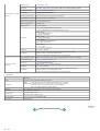
1-1. Adjustment, Periodic Maintenance, Periodic Replacement Parts, and Replacement Consumables by Service Engineer
(1) Adjustment
Adjustment
Timing
Purpose
Tool
Approx.
time
EEPROM
initialization
(EEPROM settings)
At logic board ass'y replacement
To initialize settings other than the following:
- USB serial number
- Destination setting
- Waste ink counter
- CD-R correction value
None.
1 min.
Destination settings
(EEPROM settings)
At logic board ass'y replacement
To set the destination.
None.
1 min.
LCD viewer
language settings
At logic board ass'y replacement
To set the language to be displayed on the
LCD viewer.
None.
1 min.
Waste ink counter
resetting
(EEPROM settings)
- At bottom case unit replacement
- At ink absorber (QC1-4221 / 4222 / 4223 /
4224 / 4263 / 4264 / 4864 / 4257)
replacement
To reset the waste ink counter.
None.
1 min.
CD-R sensor /
automatic print head
alignment sensor
correction (EEPROM
settings)
- At logic board ass'y replacement
- At carriage unit replacement
To correct the CD-R and automatic print head
alignment sensor.
None. (Correction
performed through
service test print)
2 min.
Print head alignment
- At print head replacement
- At logic board ass'y replacement
- At carriage unit replacement
To ensure accurate dot placement.
- None. (operation panel)
- Computer (settings via
the printer driver)
2 min.
Paper feed motor
position adjustment*1
At paper feed motor unit replacement
To adjust the belt tension. (Position the paper
feed motor so that the belt is stretched tight.)
None.
2 min.
Grease application
- At carriage unit replacement
- At chassis' upper gear replacement
- At shaft lift (QC1-4331) replacement
- To maintain sliding properties of the carriage,
carriage shaft, and shaft lift.
- To protect the chassis' upper gear.
- FLOIL KG-107A
(QY9-0057)
- MOLYKOTE HP300
(QY9-0035)
1 min.
Note: DO NOT loosen the red screws on both sides of the main chassis, securing the carriage shaft positioning.
*1: Red screws of paper feed motor
The red screws securing the paper feed motor may be loosened only at replacement of the paper feed motor unit.
(2) Periodic maintenance
No periodic maintenance is necessary.
(3) Periodic replacement parts
There are no parts in this printer that require periodic replacement by a service engineer.
(4) Replacement consumables
There are no consumables that require replacement by a service engineer.
1-2. Customer Maintenance
Adjustment
Timing
Purpose
Tool
Approx. time
Print head alignment
At print head replacement.
To ensure accurate dot placement.
- Operation panel
3 min.
- Computer (automatic settings
via the printer driver)
Print head cleaning
When print quality is not satisfying.
To improve nozzle conditions.
- Operation panel
- Computer (settings via the
printer driver)
1 min.
Print head deep
cleaning
When print quality is not satisfying, and not
improved by print head cleaning.
To improve nozzle conditions.
Computer (settings via the
printer driver)
2 min.
Ink tank replacement
When an ink tank becomes empty. (No ink
error)
Paper feed roller
cleaning
When paper does not feed properly.
To clean the paper feed rollers.
Operation panel
2 min.
CD-R print position
adjustment
At CD-R printing, when necessary
To correct CD-R print position.
Computer (application
software)
5 min.
Bottom plate cleaning
When the back side of the paper is smeared
To clean the platen ribs.
Computer (application
software)
1 min.
LCD viewer
contrast adjustment
When adjusting the contrast
To adjust the contrast
Operation panel
1 min.
1-1
-----
-----
2 min.
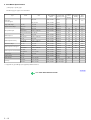
1-3. Product Life
(1) Printer
Specified print volume (I) or the years of use (II), whichever comes first.
(I) Print volume
PIXMA iP6000D
5,000 pages
Black
1,500 character pattern
1,500 pages
Color
A4, 7.5% duty per color pattern
1,300 pages
A4, 30 % duty per color pattern
400 pages
4 x 6, 30 % duty per color pattern
1,000 pages
Postcard, 30 % duty per color pattern
800 pages
(II) Years of use
5 years of use
(2) Print head
Print volume: No. of pages printed: 5,000 pages (When printing with print mode above)
(3) Ink tank (target value)
BCI-6BK: 520 pages (1,500 character pattern, plain paper / standard mode)
540 pages (ISO JIS-SCID No. 5 / plain paper / standard mode)
BCI-6C:
780 pages (ISO JIS-SCID No. 5 / plain paper / standard mode)
BCI-6M: 580 pages (ISO JIS-SCID No. 5 / plain paper / standard mode)
BCI-6Y:
360 pages (ISO JIS-SCID No. 5 / plain paper / standard mode)
BCI-6PC: 410 pages (ISO JIS-SCID No. 5 / plain paper / standard mode)
BCI-6PM: 260 pages (ISO JIS-SCID No. 5 / plain paper / standard mode)
1-4. Special Tools
Name
Tool No.
Application
Remarks
MOLYKOTE
HP300
QY9-0035-000
To be applied to the chassis' upper gear, and to the
sliding portion of the shaft lift.
In common with other
models.
FLOIL
KG-107A
QY9-0057-000
To be applied to the sliding portion of the carriage, and
the carriage shaft.
In common with other
models.
1-5. Serial Number Location
On the carriage flexible cable holder (visible when the access cover is open).
To the top
<Part 1: 1. MAINTENANCE>
1-2
2. LIST OF ERROR DISPLAY / INDICATIONS
Errors and warnings are displayed by the following ways.
1) Errors are indicated by the number of times the LED blinks.
2) Errors and warnings are displayed on the LCD viewer on the operation panel.
3) Warnings are displayed on the printer driver's Status Monitor.
2-1. Operator Call Errors (by LED Blinking in Orange)
LED blinking
in orange
2 times
3 times
Solution
Error [Error code]
No paper. (ASF) [1000]
Set the paper in the ASF, and press the Resume/Cancel
button.
No CD-R tray. [1001]*1
Set the CD-R tray, and press the Resume/Cancel button.
No paper in the cassette. [1003]
(No paper in the front paper feed cassette.)
Set the paper in the cassette, and press the Resume/Cancel
button.
Paper jam. [1300]
Remove the jammed paper, and press the Resume/Cancel
button.
Paper jam in the under guide. [1304]
Remarks
Paper jam in the rear guide. [1303]
Front door closed. [1250]
Open the paper output tray.
4 times
No ink. [1601 / 1611 / 1612 / 1613 / 1634 /
1635]
Replace the empty ink tank(s), or press the Resume/Cancel
button.
5 times
The print head is not installed [1401], or it is not Install the print head properly, and close the access cover.
Or, with the print head installed, turn the printer off and on.
properly installed (EEPROM data of the print
head is faulty) [1403 / 1405].
6 times
Inner cover open. [1841]*2
Close the inner cover, and press the Resume/Cancel button.
Inner cover open (during printing on paper).
[1846]*2
Close the inner cover, and press the Resume/Cancel button.
Pressing the
Resume/Cancel button
will exit the error without
ink tank replacement,
however, ink may run out
during printing.
CD-R tray feeder closed (during CD-R printing). Open the CD-R tray feeder, set the CD-R tray properly, and
[1850 / 1855]*1
press the Resume/Cancel button.
CD-R tray feder open (during printing on paper). Close the CD-R tray feeder, and press the Resume/Cancel
button.
[1851 / 1856]*1
7 times*1
No CD-R or DVD-R. [1002]
8 times
Warning: The waste ink absorber is almost full
Pressing the Resume/Cancel button will exit the error, and
(approx. 95% of the maximum capacity). [1700] enable printing.
In repair servicing, replace the bottom case unit (QM21496), or the ink absorbers (QC1-4221 / 4222 / 4223 / 4224 /
4257 / 4263 / 4264 / 4864 ).
9 times
The connected digital camera or digital video
After removing the cable between the camera and the printer,
camera does not support Camera Direct Printing. press the Resume/Cancel button, and re-connect the cable.
[2001]
10 times
Automatic duplex printing cannot be performed
(paper size not supported). [1310]
11 times
Failed in automatic print head alignment. [2500] Press the Resume/Cancel button, and after confirming the
following, perform print head alignment again:
- Set an appropriate type and size of paper (plain paper, A4
or letter).
- Check that the nozzle check pattern is properly printed (all
ink ejected, no faint printing).
- Protect the paper output slot from exposure to excessive
light.
Cover open. [1200]
*1: Only for models supporting CD-R printing
*2: Only for models not supporting CD-R printing
1-3
After setting a CD-R or DVD-R in the tray, set the tray in the
tray feeder, and press the Resume/Cancel button.
Press the Resume/Cancel button to eject the paper being
used at error occurrence. Printing will resume from on the
front side of the next page.
Close the cover.
The service call error,
indicating the waste ink
absorber is full, is likely to
occur soon.
Data which was to be
printed on the back side of
paper at error occurrence
is skipped (not printed).
2-2. Service Call Errors (by LED Blinking in Orange and Green Alternately, or Lit in Orange)
LED alternate
blinking in orange and
green
Solution
(Replacement of listed parts, which are likely to be faulty)
Error [Error code]
2 times
Carriage error [5100]
- Carriage unit (QM2-1499)
- Timing slit strip film (QC1-4284)
- Logic board ass'y (QM2-1786)*1
- Carriage motor (QK1-0545)
3 times
Paper feed error [6000]
- Timing sensor unit (QM2-1213)
- Timing slit disk film (QC1-4833)
- Feed roller ass'y (QL2-0598)
- Platen unit (QM2-1510)
- Logic board ass'y (QM2-1786)*1
- Paper feed motor (QK1-0550)
4 times
Purge unit error [5C00]
- Purge unit (QM2-1500)
- Logic board ass'y (QM2-1786)*1
5 times
ASF (cam) sensor error [5700]
- Sheet feed unit (QM2-1220)
6 times
Internal temperature error [5400]
- Logic board ass'y (QM2-1786)*1
7 times
Waste ink absorber full [5B00]
- Ink absorber (QC1-4221 / 4222 / 4223 / 4224 / 4257 / 4263 / 4264 / 4864 )
- Bottom case unit (QM2-1496)*2
8 times
Print head temperature rise error [5200]
- Print head (QY6-0050)
- Logic board ass'y (QM2-1786)*1
9 times
EEPROM error [6800]
- Logic board ass'y (QM2-1786)*1
11 times
Carriage lift mechanism error [5110]
- Lift shaft(QC1-4331)
- Photo interrupter (WG8-5624)
- Sheet feed unit (QM2-1220)
- Logic board ass'y (QM2-1786)*1
12 times
AP position error [6A00]
- Sheet feed unit (QM2-1220)
- Logic board ass'y (QM2-1786)*1
13 times
Paper feed position error [6B00]
- Sheet feed unit (QM2-1220)
- Logic board ass'y (QM2-1786)*1
14 times
Paper feed cam sensor error [6B10]
- Sheet feed unit (QM2-1220)
- Logic board ass'y (QM2-1786)*1
15 times
USB Host VBUS overcurrent [9000]
- Logic board ass'y (QM2-1786)*1
16 times
Valve sensor error [6C00]
- Logic board ass'y (QM2-1786)*1
17 times
Motor driver error [6D00]
- Logic board ass'y (QM2-1786)*1
20 times
Other hardware error [6500]
- Logic board ass'y (QM2-1786)*1
Continuous alternate
blinking
ROM error
- Logic board ass'y (QM2-1786)*1
Lights in orange
RAM error
- Logic board ass'y (QM2-1786)*1
*1: Before replacement of the logic board ass'y, check the waste ink amount (by service test print or EEPROM information print). If the waste ink amount is 7%
or more, also replace the bottom case unit (QM2-1496) or the ink absorbers (QC1-4221/ 4222 / 4223 / 4224 / 4257 / 4263 / 4264 / 4864 ) when replacing
the logic board ass'y.
[See Section 3-3. Adjustment / Settings, (6) Service mode, for details.]
*2: Reset the waste ink counter when replacing the bottom case unit.
[See Section 3-3. Adjustment / Settings, (6) Service mode, for details.]
2-3. Warnings
Printer (displayed on the LCD viewer):
Displayed warning
Remarks
Low ink of 6BK, 6C, 6M, 6Y, 6PC, or 6 PM (at
detection of no remaining raw ink)
Print head temperature rise
If the print head temperature is high when the access cover is opened, the warning is displayed*1.
When the print head temperature falls, the warning is released.
Protection of excess rise of the print head temperature
If the print head temperature exceeds the specified limit, a Wait is inserted during printing,
*1: If the warning is displayed, the carriage does not move to the ink tank replacement position when the access cover is opened.
1-4
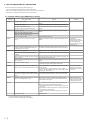
2-4. Troubleshooting by Symptom
Symptom
Replace the
- AC adapter, or
- logic board ass'y*1.
Strange noise.
Remove foreign material, or attach a removed part if
any.
Printing stops mid-way.
Replace the logic board ass'y*1.
Multiple sheets feed.
Replace the
- sheet feed unit, or
- cassette.
Paper does not feed.
Remove foreign material, or replace the
- sheet feed unit, or
- cassette.
Paper feeds at an angle.
Remove foreign material, or adjust the paper guide, or
replace the
- sheet feed unit, or
- cassette.
No printing, or no color ejected.
Replace the
- ink tank,
- print head*2,
- logic board ass'y*1, or
- purge unit.
Printing is faint, or white lines appear on printouts
even after print head cleaning.
Line(s) not included in the print data appears on
printouts.
Remove and re-install the print head, or replace the
- ink tank,
- print head*2,
- purge unit, or
- logic board ass'y*1.
Paper gets smeared.
Feed several sheets of paper,
perform bottom plate cleaning, or
clean the paper path with cotton swab or cloth.
A part of a line is missing on printouts.
Replace the
- ink tank, or
- print head*2.
Color hue is incorrect.
Replace the
- ink tank, or
- print head*2, or
perform print head alignment.
Printing is incorrect.
Replace the logic board ass'y*1.
No ejection of black ink.
Replace the
- ink tank, or
- print head*2.
Graphic or text is enlarged on printouts.
When enlarged in the carriage movement direction,
clean grease or oil off the timing slit strip film, or
replace the
- timing slit strip film,
- carriage unit, or
- logic board ass'y*1.
When enlarged in the paper feed direction, clean
grease or oil off the timing slit disk film, or replace the
- timing slit disk film,
- timing sensor unit, or
- logic board ass'y*1.
Faulty operation
Paper feed
problems
Unsatisfactory
print quality
Solution
The power does not turn on.
The power turns off immediately after power-on.
Remarks
*1: Before replacement of the logic board ass'y, check the waste ink amount (by service test print or EEPROM information print). If the waste ink amount is 7%
or more, also replace the bottom case unit (QM2-1496) or the ink absorbers (QC1-4222 / 4223 / 4224 / 4263 / 4264 / 4864 / 4221 / 4257) when replacing
the logic board ass'y.
[See Section 3-3. Adjustment / Settings, (6) Service mode, for details.]
*2: Replace the print head only after the print head deep cleaning is performed 2 times, and when the problem persists.
To the top
<Part 1: 2. LIST OF ERROR DISPLAY / INDICATION>
1-5
3. REPAIR
3-1. Notes on Service Part Replacement (and Disassembling / Reassembling)
Service part
Logic board ass'y
QM2-1786
Notes on replacement*1
Adjustment / settings
- Before removal of the logic board
ass'y, remove the power cord, and
allow for to sit approx. 1 minute (for
discharge of capacitor's accumulated
charges), to prevent damage to the
logic board ass'y.
- Before replacement, check the waste
ink amount (by service test print or
EEPROM information print). If the
waste ink amount is 7% or more, also
replace the bottom case unit or the ink
absorbers when replacing the logic
board ass'y.
[See 3-3. Adjustment / Settings, (6)
Service mode, for details.]
After replacement:
1. Initialize the EEPROM.
2. Reset the waste ink counter.
3. Set the destination in the EEPROM.
4. Set the LCD viewer language.
5. Correct the CD-R and automatic print
head alignment sensors.
[See 3-3. Adjustment / Settings, (6)
Service mode, for details of 1 to 5]
6. Perform the print head alignment in
the user mode.
- EEPROM information print
- Service test print
- Printing via parallel or USB
connection
After replacement:
1. Reset the waste ink counter.
[See 3-3. Adjustment / Settings, (6)
Service mode.]
- Service test print
At replacement:
1. Apply grease to the sliding portions.
[See 3-3. Adjustment / Settings, (3)
Grease application.]
- Service test print (Confirm CD-R
and automatic print head alignment
sensor correction.)
Bottom case unit
QM2-1496
Ink absorber
QC1-4221 / 4222 / 4223 /
4224 / 4257 / 4263 / 4264 /
4864
Carriage unit
QM2-1499
Operation check
- Direct printing from a digital camera
- Direct printing from a memory card
- Print Beam printing
After replacement:
1. Correct the CD-R and automatic print
head alignment sensors.
[See 3-3. Adjustment / Settings, (6)
Service mode.]
2. Perform the print head alignment in
the user mode.
Paper feed motor unit
QK1-0550
- The red screws securing the paper feed At replacement:
motor are allowed to be loosened.
1. Adjust the paper feed motor.
(DO NOT loosen any other red
[See 3-3. Adjustment / Settings, (1)
screws.)
Paper feed motor adjustment.]
Shaft lift
QC1-4331
Timing slit strip film
QC1-4284
Timing slit disk film
QC1-4833
Print head
QY6-0050
- Upon contact with the film, wipe the
film with ethanol.
- Confirm no grease is on the film.
(Wipe off any grease thoroughly with
ethanol.)
- Do not bend the film
At replacement:
1. Apply grease to the sliding portions.
[See 3.3. Adjustment / Settings, (3)
Grease application.]
- Service test print
After replacement:
1. Perform the print head alignment in
the user mode.
- Service test print
After replacement:
1. Perform the print head alignment in
the user mode.
- Service test print
*1: General notes:
- Make sure that the flexible cables and wires in the harness are in the proper position and connected correctly.
[See 3-2. Special Notes on Repair Servicing, (1) Flexible cable and harness wiring, connection, for details.]
- Do not drop the ferrite core, as it may damage the core.
- Protect electrical parts from damage due to static electricity.
- Before removing a unit, after removing the power cord, allow the printer to sit for approx. 1 minute (for capacitor discharging to protect the logic board
ass'y from damages).
- Do not touch the timing slit strip film and timing slit disk film. No grease or abrasion is allowed.
- Protect the units from becoming soiled with ink.
- Protect the housing from scratches.
- Exercise caution with the red screws, as follows:
i. The red screws of the paper feed motor may be loosened only at replacement of the paper feed motor unit (DO NOT loosen them in other cases).
ii. DO NOT loosen the red screws on both sides of the main chassis, securing the carriage shaft positioning (they are not adjustable in servicing).
<Part 1: 3. REPAIR, 3-1>
1-6
To the top
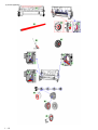
3-2. Special Notes on Repair Servicing
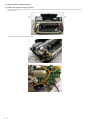
(1) Flexible cable and harness wiring, connection
Exercise care when handling the flexible cables and harness wiring. Improper wiring or connection may cause a short-circuit, and may lead to ignition or
emission of smoke.
(I) Logic board ass'y and operation panel unit wiring
1-7
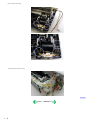
(II) DCC holder unit wiring
(III) Paper feed motor side wiring
To the top
<Part 1: 3. REPAIR, 3-2>
1-8
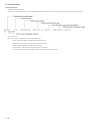
3-3. Adjustment / Settings
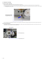
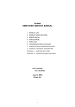
(1) Paper feed motor adjustment
Perform the following adjustments when the paper feed motor unit is replaced:
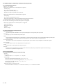
1) When attaching the motor, fasten the screws so that the belt is properly stretched (in the direction indicated by the blue arrow in the figure below).
2) After replacement, be sure to perform the service test print, and confirm that no strange noise or faulty print operation (due to dislocation of the belt or gear,
or out-of-phase motor, etc.) occurs.
Note: The red screws securing the paper feed motor may be loosened only at replacement of the paper feed motor unit. DO NOT loosen them in other cases.
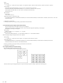
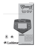
(2) Gear phase adjustment
In attaching the lift transmission gear (QC1-4327), adjust the phase so that the protrusion of the lift transmission gear (QC1-4327) fits into the recess of the
carriage shaft cam R (QC1-4282), as shown in the figure below.
1-9
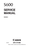
(3) Grease application
1 - 10
Part name
Chassis
Where to apply grease / oil
Grease / oil name
Grease / oil
amount
1
Entire contact surface of the carriage slider rail
FLOIL KG107A
3 drops
2
Cam contact portion
FLOIL KG107A
1 drop
3
Carriage shaft sliding portion
FLOIL KG107A
1 drop
4
Carriage shaft cam L sliding portion
MOLYKOTE HP300
2 drops
5
Carriage shaft sliding portion
FLOIL KG107A
1 drop
6
Carriage shaft sliding portion on the left side of the chassis
FLOIL KG107A
1 drop
7
Carriage shaft cam L sliding portion on the left side of the chassis
FLOIL KG107A
2 drops
8
Carriage shaft sliding portion on the right side of the chassis
FLOIL KG107A
1 drop
Carriage shaft
9
Entire surface of the carriage shaft where the carriage unit slides
FLOIL KG107A
200 to 400mg
Carriage shaft spring L
10
Carriage shaft sliding portion (over the area more than 2/3 from the top
end of the spring)
FLOIL KG107A
1 drop
Lift gear 2 shaft
11
Outer surface of the stepped portion where the spring slides
MOLYKOTE HP300
1 drop
Lift gear 2
12
Outer surface of the spring sliding bushing
MOLYKOTE HP300
1 drop
Chassis
13
Carriage shaft cam R sliding portion
MOLYKOTE HP300
1 drop
Transmission gear
14
Inner surface
MOLYKOTE HP300
1 drop
Lift shaft
15
Spring sliding portion (4 locations)
FLOIL KG107A
1 drop
16
Pressure roller ass'y contact portion (4 locations)
FLOIL KG107A
1 drop
17
Spring contact bushing
FLOIL KG107A
Half drop
Feed roller ass'y
Note: 1 drop = 9 to 18 mg
To the top
<Part 1: 3. REPAIR, 3-3 (1) to (3)>
1 - 11
(4) Waste ink counter setting
When the logic board ass'y is replaced, reset the waste ink counter. In addition, according to the waste ink amount, replace the waste ink absorber (the bottom
case unit or the ink absorbers). The standard amount for waste ink absorber replacement is given in the table below.
Waste ink amount*1
Bottom case unit or ink absorber replacement
Less than 7%
Not required.
7% or more
Required.
*1: Check the waste ink amount by service test print or EEPROM information print.
[See 3-3. Adjustment / Settings, (6) Service mode, for details.]
(5) User mode
Function
Procedures
Remarks
Nozzle check pattern printing
On standalone printers, press the Menu button
to move to Maintenance, and perform the
selection. (Nozzle check)
Also available from “Standalone
printer operation 2” below or printer
driver's maintenance sheet.
Print head manual cleaning
Cleaning both black and color:
Also available from “Standalone
printer operation 2” below or printer
driver's maintenance sheet.
On standalone printers, press the Menu button
to move to Maintenance, and perform the
selection. (Head cleaning)
Print head deep cleaning
Cleaning both black and color:
On standalone printers, press the Menu button
to move to Maintenance, and perform the
selection. (Deep cleaning)
Also available from “Standalone
printer operation 2” below or printer
driver's maintenance sheet.
Automatic print head
alignment
On standalone printers, press the Menu button
to move to Maintenance, and perform the
selection. (Auto head align)
Also available from “Standalone
printer operation 2” below or printer
driver's maintenance sheet.
Manual print head alignment
On standalone printers, press the Menu button
to move to Maintenance, and perform the
selection. (Manual head align)
In Custom Settings of the printer
driver's Maintenance sheet, manual
print head alignment (by selecting the
optimum values) as with the conventional
models can be performed.
Print head alignment values printing
Print and confirm the print head alignment values set in
the printer.
On standalone printers, press the Menu button to move to
Maintenance, and perform the selection. (Manual head
align)
Head-to-paper distance setting
The head-to-paper distance setting can be set to Auto or
Thick paper.
On standalone printers, press the Menu button to move to
Maintenance, and perform the selection. (Thick paper)
Contrast adjustment
The contrast of the LCD viewer on the printer can be
adjusted.
On standalone printers, press the Menu button to move to
Maintenance, and perform the selection. (Contrast)
Quiet mode setting
The quiet mode can be set to On or Off.
Also available from printer driver's maintenance
sheet.
On standalone printers, press the Menu button to move to
Maintenance, and perform the selection. (Quiet mode)
Language selection
Languages to be displayed on the LCD viewer of the
printer can be set.
On standalone printers, press the Menu button to move to
Maintenance, and perform the selection. (Languages)
Paper feed roller cleaning
See “Standalone printer operation 2” below.
Bottom plate cleaning
See “Standalone printer operation 2” below, or perform
from the printer driver's Maintenance tab.
Print head replacement
The print head is replaceable at the same time position as
for ink tank replacement.
(Open the cover. When the carriage stops at the center, the
print head can be replaced.)
1 - 12
Clean the platen ribs when the back side of paper
gets smeared.
<Standalone printer operation>
1) Turn on the printer.
2) Press and hold the Resume/Cancel button until the LED blinks the specified number of times listed in the table below, and release it. The operation starts.
LED blinking
Operation
Remarks
1 time
Print head manual cleaning
2 times
Nozzle check pattern printing
3 times
Paper feed roller cleaning
4 times
Automatic print head alignment
Set a sheet of plain paper (A4 or letter) in the sheet feeder.
5 times
Bottom plate cleaning
Fold a sheet of plain paper (A4 or letter) in half crosswise, then unfold and set it
in the sheet feeder with the folded ridge facing down.
6 times
Unspecified
7 times
Set the widest head-to-paper distance
Set a sheet of plain paper (A4 or letter) in the sheet feeder or the cassette
(according to the Paper Feed switch setting).
(6) Service mode
Function
Service test print
- Model name
- ROM version
- USB serial number
- Waste ink amount
Procedures
Remarks
See "Service mode operation procedures" below. Set a sheet of A4 or letter- sized paper.
For a print sample, see 3-4. Verification Items, (1) Service
test print, <Service test print sample>.
- CD-R sensor correction
- LCD viewer language settings
EEPROM information print
See "Service mode operation procedures" below. Set a sheet of A4 or letter- sized paper.
For a print sample, see 3-4. Verification Items, (2)
EEPROM information print
EEPROM initialization
See "Service mode operation procedures" below. The following items are NOT initialized:
- USB serial number
- Destination settings
- Waste ink counter
- CD-R correction value
Waste ink counter reset
See "Service mode operation procedures" below. If the waste ink amount is 7% or more, replace the bottom
case unit, or the ink absorbers.
Destination settings
See "Service mode operation procedures" below. Other than Japan: iP6000D
Japan: iP6100D
Button/LCD viewer test
See "Service mode operation procedures" below. Confirm the operation button operation and the LCD
viewer display. Perform them at the operation panel
replacement.
Note: At the end of the service mode, press the Power button. At that time, the paper lifting plate of the sheet feeder unit will be raised.
1 - 13
<Service mode operation procedures>
1) With the printer power turned off, while pressing the Resume/Cancel button, press and hold the Power button. (DO NOT release the buttons. The LED lights
in green to indicate that a function is selectable.)
2) While holding the Power button, release the Resume/Cancel button. (DO NOT release the Power button.)
3) While holding the Power button, press the Resume/Cancel button 2 times, and then release both the Power and Resume/Cancel buttons. (Each time the
Resume/Cancel button is pressed, the LED lights alternately in orange and green, starting with orange.)
4) When the LED lights in green, press the Resume/Cancel button the specified number of time(s) according to the function listed in the table below. (Each time
the Resume/Cancel button is pressed, the LED lights alternately in orange and green, starting with orange.)
Time(s)
LED
Function
Remarks
0 times
Green
Power off
When the print head is not installed, the carriage returns and
locks in the home position.
1 time
Orange
Service test print
See 3-4. Verification Items, (1) Service test print.
2 times
Green
EEPROM information print
See 3-4. Verification Items, (2) EEPROM information print.
3 times
Orange
EEPROM initialization
4 times
Green
Waste ink counter resetting
5 times
Orange
Destination settings
6 times
Green
Print head deep cleaning
7 times
Orange
CD-R test print
Not used in servicing.
8 times
Green
CD-R print position correction
(horizontal)
Not used in servicing.
9 times
Orange
CD-R print position correction
(vertical)
Not used in servicing.
10 times
Green
Button and LCD viewer test
11 times or more
Proceed to the following step 5), and follow the Destination
settings procedures.
Proceed to the following step 5), and follow the Button and
LCD viewer test procedures.
Return to the menu selection
5) After the function (menu) is selected, press the Power button. The LED lights in green, and the selected function is performed. (When the operation
completes, the printer returns to the menu selection mode automatically.)
<Destination settings procedures>
In the destination settings mode, press the Resume/Cancel button the specified number of time(s) according to the destination listed in the table below, and press
the Power button.
Time(s)
LED
1 time
Orange
Japan: iP6100D
2 times
Green
Other than Japan, non-support of CD-R printing (A4): iP6000D (A4)
3 times
Orange
Other than Japan, non-support of CD-R printing (LTR): iP6000D (LTR)
4 times
Green
Other than Japan, support of CD-R printing (A4): iP6000D (A4)
5 times
Orange
Other than Japan, support of CD-R printing (LTR): iP6000D (LTR)
6 times or
more
Destination
Return to the menu selection
Note: After setting the destination, confirm the model name in the service test print or EEPROM information print.
[See 3-4. Verification Items, (1) Service test print, or (2) EEPROM information print.]
1 - 14
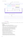
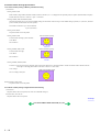
<Button and LCD viewer test>
After moving to the button and LCD viewer test mode, perform the following to check the operation of buttons and the LCD viewer display.
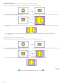
1) Press the Paper Feed switch. The LCD viewer's color will change and display “blue” full-screen. (If an error has occurred, the error LED lights. In this case,
input other than the Power button is not possible. Re-enter service mode to perform this test.)
2) Press each button on the operation panel (excluding the Power and Resume buttons). Each time each button is pressed, a part of the display will change to
“red”. (The area changed to "red" is as shown in the diagram below. The figure shows the display when both the Menu and OK buttons are pressed.)
===LCD viewer display===
3) Press all buttons, excluding the Power button and Resume button. The entire LCD viewer will change to display “red” full-screen.
4) Open the cover to display the color pattern.
5) Press the Power button to return to the service mode function selection status.
To the top
<Part 1: 3. REPAIR, 3-3 (4) to (7)>
1 - 15
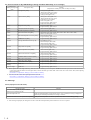
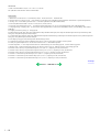
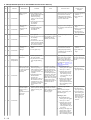
3-4. Verification Items
(1) Service test print
<EEPROM information contents>
On the service test print (sample below), confirm the EEPROM information as shown below. (The information is given in the upper portion of the printout.)
<Print check items>
On the service test print (sample below), confirm the following items:
- Check 1, nozzle check pattern: Ink shall be ejected from all nozzles
- Check 2, top of form accuracy: The line shall not extend off the paper.
- Check 3, vertical straight lines: The line shall not be broken.
- Check 4, halftone: There shall be no remarkable streaks or unevenness.
- Check 5, CD-R / automatic print head alignment sensor correction: The results shall be OK.
1 - 16
<Service test print sample>
(2) EEPROM information print
<How to read the EEPROM information print>
Print sample:
1:iPXXXXD 2:V1.00 3:IF(USB1=1) 4:D=004.5 5:ST=2004/05/27-18:30
6:ER(ER0=1000 ER1=5100 7:LPT=2004/06/03-09:09 8: PC(M=002 R=000 T=001 D=009 C=009)
9:CLT(2004/06/19-18:30) 10:CH=00002 11:CT(BK=002 C=001 M=000 Y=001 PC=002 PM=002)
12:IS(BK1=1 C=1 M=1 Y=1 PC=1 PM=1) 13:Power(SON=00061 SOFF=00041 HON=00029)
14:A_REG=1 15:M_REG=0 16: UR(A=+01 B=000 C=000 D=00 E=000 F=+01 G=000 H=000)
17:LG=01 Japanese 18:WP=0024 19:CDIN(LG=001 PB=000 OPB=000) 20:MSD(015)
21:Tpage(00398) 22:PAGE(All=00074 PP=00027 HR=00043 MP=00000 PR=00003
SP+GP=00001 GP=00000 PC=00000 ENV=00000) 23: UCPAGE(All=00312 PP=00280
HR=00032 MP=00000 PR=00000 SP+SG=00000 GP=00000 PC=00000 ENV=00000)
24:BPPAGE(All=00000 BSGP=000030 PC=00000)
25:CDPAGE(All=000) 26:EDGE=00003 27:L=00004 28:CDR=00012
29:CDRP=(+00196,-00283) 30:CDRS=(030) 31:Head Temp=31.0
32:Env Temp=27.5 33:FF(07 80 00) 34:OPP=00000 35 :PrnB=00000 36:Seal=00000
37:CardPaper=00001 38:CardIns(0081) 39:CardPrn(0008)
40:CardD-PR(L/4x6=0002 2L/5x7=0000 JPC=0000 A4/LTR=0000)
41:CardD-SP(L/4x6=0002 2L/5x7=0000 JPC=0000 A4/LTR=0000)
42:CardD-MP(L/4x6=0002 2L/5x7=0000 JPC=0000 A4/LTR=0000)
43:CameraD-Photo Paper(L/4x6=0000 2L/5x7=0000 JPC=0000 A4/LTR=0000)
44:CameraD-Fast Photo Paper(L/4x6=0000 2L/5x7=0000 JPC=0000 A4/LTR=0001)
45:CameraD-Matte Photo Paper(L/4x6=0000 2L/5x7=0000 JPC=0000 A4/LTR=0000)
1 - 17
HDEEPROM
1:V0001 2:SN=0000-08D6 3:LN(15 15 15 15 63 63 15) 3: ID=00
4:IL=(BK=000 C=000 M=000 Y=000 PC=000 PM=000)
Printed items:
1. Model name 2. ROM Version 3. Connected I/F (USB1) 4. Waste ink amount 5. Installation date
6. Operator call/service call error record 7. Last printing time 8. Purging count (manual/deep cleaning/timer/dot count/ink tank or print head replacement)
9. Cleaning time 10. Print head replacement count 11. Ink tank replacement count (BK/C/M/Y/PC/PM)
12. Ink status (BK/C/M/Y/PC/PM 13. Power-on count (soft-on, soft-off, hard-on)
14. Automatic print head alignment by user 15. Manual print head alignment by user 16. User print head alignment value (A/B/C/D/E/F/G/H)
17. Language settings 18. Wiping count 19. Camera Direct Print-supported device connection record (Bubble Jet Direct, Canon PictBridge, Other maker's
PictBridge)
20. Longest period of non-printing 21. Total pages fed
22. Sheet feeder pages fed (total, plain paper, High Resolution Paper & Matte Photo Paper, Photo Paper Pro & Photo Paper Plus Glossy & Photo Paper Plus
Semi-gloss, Glossy Photo Paper, Postcard, Envelope)
23. Cassette feeder pages fed (total, plain paper, High Resolution Paper & Matte Photo Paper, Photo Paper Pro & Photo Paper Plus Glossy & Photo Paper Plus
Semi-gloss, Glossy Photo Paper, Postcard, Envelope)
24. Auto duplex print pages (total, Photo Paper Plus Double Sided, postcard)
25. Camera Direct print pages (total) 26. Borderless print pages 27. L & 4x6 print pages 28. Number of CD-Rs printed
29. CD-R print position adjustment 30. CD-R sensor correction value 31. Print head temperature
32. Inside temperature 33. Line inspection information 34. Other Photo Paper 35. Print Beam pages fed 36. Photo Stickers pages fed
37. Business card + Credit card sized paper pages fed 38. Memory card use count 39. Total direct memory card printing pages fed
40. Number of direct memory card print: Photo Paper Pro (L/4 x 6, 2L/5 x 7, Japanese post card, and A4/Letter)
41. Number of direct memory card print: Photo Paper Plus Glossy (L/4 x 6, 2L/5 x 7, Japanese post card, and A4/Letter)
42. Number of direct memory card print: Matte Photo Paper (L/4 x 6, 2L/5 x 7, Japanese post card, and A4/Letter)
43. Number of Camera Direct print: Photo Paper (L/4 x 6, 2L/5 x 7, Japanese post card, and A4/Letter)
44. Number of Camera Direct print: Fast Photo Paper (L/4 x 6, 2L/5 x 7, Japanese post card, and A4/Letter)
45. Number of Camera Direct print: Matte Photo Paper (L/4 x 6, 2L/5 x 7, Japanese post card, and A4/Letter)
To the top
<Part 1: 3. REPAIR, 3-4>
1 - 18
4. PRINTER TRANSPORTATION
This section describes the procedures for transporting the printer for returning after repair, etc.
1) In the service mode, press the Power button to finish the mode, and confirm that the paper lifting plate of the sheet feeder unit is raised.
2) Keep the print head and ink tanks installed in the carriage.
[See Caution 1 below.]
3) Turn off the printer to securely lock the carriage in the home position. (When the printer is turned off, the carriage is automatically locked in place.)
[See Caution 2 below.]
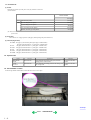
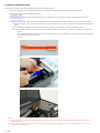
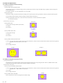
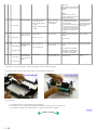
4) To further secure the carriage to prevent movement from the home position during transportation, make and use a fixing tool in the following procedures:
i. Fold an A4-sized paper 5 times, and wrap it twice with tape, as shown in Figure A below (to prevent the fixing tool from caught into the inside of the
printer).
ii. Insert the fixing tool between the carriage and the main case unit, and securely fix it with tape, as shown in Figures B and C below.
Note: The tape should be similar to the polyester tape used at shipment, which will not easily be torn or removed, or leave adhesive on the unit when
removed.
Leave a sufficient length of tape to fix the tool so that the tape end is easily seen even when the cover is closed, so that the user will remove the
tool from the returned printer without fail.
Figure A:
Figure B:
Figure C:
Caution:
(1) If the print head is removed from the printer and left alone by itself, ink is likely to dry. For this reason, keep the print head installed in the printer even
during transportation.
(2) Securely lock the carriage in the home position, to prevent the carriage from moving and applying stress to the carriage flexible cable or causing ink
leakage during transportation.
1 - 19
Part 2
TECHNICAL REFERENCE
1. NEW TECHNOLOGIES
(1) Multi-paper handling
Paper feeding through the auto sheet feeder and the cassette, automatic duplex printing, and CD-R / DVD-R direct printing are available as standard features.
- Sheet feeder: Supports name/credit card size and sticker sheets as well as conventional paper types and sizes.
- Front cassette: Except name, credit card and legal size and sticker sheets, supports the same types and sizes of paper as the sheet feeder.
- Automatic duplex printing unit built-in: Using Photo Paper Plus Double Sided, photo albums can be created automatically.
- CD-R / DVD-R direct printing unit built-in: By incorporating CD-R / DVD-R tray feeder functionality into the printer, CD-R / DVD-R direct printing is
possible.
- Front loading and operation without lever settings offers easy and quick printing.
(2) New design
- Complete renovation to a new generation printer design
- Elegant-looking housing with mirror finished surfaces
(3) Automatic duplex printing unit installed as a standard feature
For the following paper types and sizes, automatic duplex printing can be performed:
- Type: Plain paper, Super White Paper (double-sided plain paper), Photo Paper Plus Double Sided (double-sided glossy photo paper)
- Size: A5, B5, 5" x 7", A4, LTR
(4) Card direct printing
a. By using a menu-format GUI utilizing a newly adopted 2.5 inch built-in LCD Viewer (versus 2.0 inch for the i900D), printing the desired output can be
performed.
- Image search (function to search photos)
- Color adjustment (brightness, contrast, hue) and process (sepia, simulate illustration)
- Color adjustment printing (possible to change to preferred colors after sample printing)
b. Memory Stick PRO and Memory Stick PRO Duo (adapter required) are also supported.
(5) Print Beam supported
Direct Printing from a camera-equipped mobile phone can be performed using infrared communication. (not compatible with computer and PDA for printing,
and text printing is not possible.)
(6) CD-R direct printing without use of a CD-R tray feeder (applicable only to specific regions)
By incorporating CD-R tray feeder functionality into the printer, CD-R direct printing can be performed without using a CD-R tray feeder.
To the top
<Part 2: 1. NEW TECHNOLOGIES>
2-1
2. CLEANING MODE AND AMOUNT OF INK PURGED
To prevent printing problems due to bubbles, dust, or ink clogging, print head cleaning is performed before the start of printing, except in the following cases:
- Cleaning on arrival: Performed when the access cover is closed.
- Cleaning by dot count: Performed after ejection of paper (or after printing on the back side of paper when auto duplex printing is performed).
- Manual cleaning / deep cleaning: Performed manually.
<Cleaning mode list>
Condition
Details
Amount of ink used (g)
Est. required time (sec.)
On arrival of the printer
First and second cleaning after shipped from the plant.
1.80
70
Dot count cleaning
When the specified number of dots are printed since the
previous cleaning. (Large and small nozzles for cyan and
magenta counted separately.)
0.60
40
Timer cleaning - 1
If 120 to 336 hours have elapsed since the previous
cleaning till the start of the next printing.
Timer cleaning - 2
If more than 336 hours have elapsed since the previous
Black cleaning till the start of the next printing.
1.20
55
If the print head is un-capped
at power-on
However, 0.70 at Bk/Y ink
tank replacement
At ink tank replacement
At print head replacement
Manual cleaning
- Via the operation panel
1.80
70
0.60
40
1.20
55
- Via the printer driver
Deep cleaning
- Via the operation panel
- Via the printer driver
To the top
<Part 2: 2. CLEANING MODE AND AMOUNT OF INK PURGED>
2-2
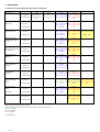
3. PRINT MODE
3-1 Resolution by Print Mode during Printing via Computer
Paper type
Plain paper
No. of passes
Resolution (dpi)
High Resolution Paper
(HR-101N)
Quality level 5
1 pass
Bk: 300 x 300
Y, M, C: 300 x
300
Quality level 4
1 pass
Bk: 300 x 300
Y, M, C: 300 x
300
No. of passes
Resolution (dpi)
Photo Paper Pro
(PR-101/PH-101)
No. of passes
Resolution (dpi)
Glossy Photo Paper
(GP-401/ KH-201N/
EC-101)
Quality level 3
Quality level 2
2 passes
6 passes
Bk, Y: 600 x 1200 Bk, Y: 600x1200
M, C: 600 x 600 M, C, Pm, Pc: 600
x 600
6 passes
8 passes
Bk, Y: 600 x 1200 Bk, Y: 600 x 1200
M, C, Pm, Pc:
M, C, Pm, Pc: 600
600x 600
x 600
6 passes
8 passes
16 passes
Bk, Y: 600 x 1200 Bk, Y: 600 x 1200 Bk, Y, M, C, Pm, Pc:
M, C, Pm, Pc:
M, C, Pm, Pc: 600
600x 600
x 600
4800 x 1200
Resolution (dpi)
6 passes
8 passes
Bk, Y: 600 x 1200 Bk, Y: 600 x 1200
M, C, Pm, Pc:
M, C, Pm, Pc: 600
600x 600
x 600
Photo Paper Plus Glossy
(PP-101/ SG-101/ KM- No. of passes
101/ MM-101)
Resolution (dpi)
6 passes
8 passes
Bk, Y: 600 x 1200 Bk, Y: 600 x 1200
M, C, Pm, Pc:
M, C, Pm, Pc: 600
600x 600
x 600
Matte Photo Paper
(MP-101)
Resolution (dpi)
6 passes
8 passes
Bk, Y: 600 x 1200 Bk, Y: 600 x 1200
M, C, Pm, Pc: 600 M, C, Pm, Pc: 600
x 600
x 600
No. of passes
Resolution (dpi)
6 passes
Bk, Y: 600 x 1200
M, C: 600 x 600
No. of passes
Resolution (dpi)
6 passes
8 passes
Bk, Y: 600 x 1200 Bk, Y: 600 x 1200
M, C: 600 x 600
M, C: 600 x 600
T-Shirt Transfers
(TR-301)
Transparencies
(CF-102)
CD-R
(suggested media/
others)
No. of passes
No. of passes
No. of passes
Resolution (dpi)
Photo Paper Plus
Sided
No. of passes
(PP-101D)
Resolution (dpi)
Other Photo Paper *
No. of passes
Resolution (dpi)
White background: Printed with 5 pl only
Yellow background: Printed with 5 pl and 2 pl (Bk/Y is printed with 5 pl only.)
Green text: Draft
Blue text: Standard
Red text: High
*: iP6000D only
2-3
Quality level 1
6 passes
8 passes
12 passes
Bk, Y: 600 x 1200 Bk, Y: 600 x 1200 Bk, Y: 600 x 1200
M, C, Pm, Pc: 600 M, C, Pm, Pc: 600 M, C, Pm, Pc: 600 x
x 600
x 600
600
6 passes
8 passes
Bk, Y: 600 x 1200 Bk, Y: 600 x 1200
M, C, Pm, Pc:
M, C, Pm, Pc: 600
600x 600
x 600
8 passes
Bk, Y: 600 x 1200
M, C, Pm, Pc: 600
x 600
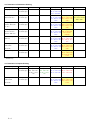
3-2 Resolution in Borderless Printing
Paper type
Plain paper
Quality level 5
Quality level 4
No. of passes
Quality level 3
Quality level 2
Quality level 1
8 passes
16 passes
2 passes
Resolution (dpi)
Bk, Y: 600 x 1200
M, C: 600x600
Photo Paper Pro
No. of passes
(PR-101/PH-101)
Resolution (dpi)
Glossy Paper
No. of passes
(GP-401/ KH-201N/
EC-101)
Resolution (dpi)
6 passes
Bk, Y: 600 x 1200 Bk, Y: 600 x 1200 Bk, Y, M, C, Pm, Pc:
M, C, Pm, Pc: 600 M, C, Pm, Pc: 600
4800 x 1200
x 600
x600
6 passes
Photo Paper Plus Glossy No. of passes
(PP-101/ SG-101/
KM-101/ MM-101)
Resolution (dpi)
Matte Photo Paper
No. of passes
(MP-101)
Resolution (dpi)
Photo Paper Plus
No. of passes
Doble Sided
Resolution (dpi)
6 passes
8 passes
Bk, Y: 600 x 1200
M, C, Pm, Pc: 600
x 600
Bk, Y: 600x1200
M, C, Pm, Pc:
600x600
6 passes
8 passes
Bk, Y: 600 x 1200 Bk, Y: 600 x 1200
M, C, Pm, Pc: 600 M, C, Pm, Pc: 00 x
x 600
600
6 passes
8 passes
Bk, Y: 600 x 1200 Bk, Y: 600 x 1200
M, C, Pm, Pc: 600 M, C, Pm, Pc: 600
x 600
x600
(PP-101D)
Other Photo Paper *
8 passes
Bk, Y: 600 x 1200 Bk, Y: 600 x 200
M, C, Pm, Pc: 600 M, C, Pm, Pc: 600
x 600
x600
No. of passes
8 passes
Resolution (dpi)
Bk ,Y: 600 x 1200
M, C, Pm, Pc: 600
x 600
*: iP6000D only
3-3 Resolution in Duplex Printing
Paper type
plain paper
No. of passes
Resolution (dpi)
Photo Paper Plus
No. of passes
Double Sided
Resolution (dpi)
(PP-101D)
2-4
Quality level 5
Quality level 4
Quality level 3
Quality level 2
1 pass
1 pass
2 passes
6 passes
Bk: 300 x 300
Y, M, C: 300 x
300
Bk: 300 x 300
Y, M, C: 300 x
300
Bk, Y: 600 x 1200 Bk, Y: 600 x 1200
M, C: 600 x 600
M, C: 600 x 600
6 passes
8 passes
Bk, Y: 600 x 1200 Bk, Y: 600 x 1200
M, C, Pm, Pc: 600 M, C, Pm, Pc: 600
x 600
x 600
Quality level 1
3-4 Resolution in Direct Printing
Paper type
Plain paper
No. of passes
Resolution (dpi)
Photo Paper Pro
No. of passes
(PR-101/ SG-101/ KM-101/ MM-101) Resolution (dpi)
Photo Paper Plus Glossy
No. of passes
(PP-101/ SG-101/ KM-101/ MM-101/ Resolution (dpi)
GP-401/ EC-101/ KH-201N)
Matte Photo Paper
No. of passes
(MP-101/HR-101S)
Resolution (dpi)
2-5
Draft
High
6 passes
8 passes
Bk, Y: 600 x 1200
Bk, Y: 600 x 1200
M, C, Pm, Pc: 600 x 600
M, C, Pm, Pc: 600 x 600
8 passes
8 passes
Bk, Y: 600 x 1200
Bk, Y: 600 x 1200
M, C, Pm, Pc: 600 x 600
M, C, Pm, Pc: 600 x 600
8 passes
8 passes
Bk, Y: 600 x 1200
Bk, Y: 600 x 1200
M, C, Pm, Pc: 600 x 600
M, C, Pm, Pc: 600 x 600
6 passes
8 passes
Bk, Y: 600 x 1200
Bk,Y: 600 x 1200
M, C, Pm, Pc: 600 x 600
M, C, Pm, Pc: 600 x 600
4. PHOTO DIRECT PRINT FUNCTION
4-1 Host PC Memory Card Access Function with the Memory Card Startup Utility
4-1-1 Supported memory cards
Media types compatible with the host computer memory card access function and Memory Card Direct Printing function are as follows:
- Compact Flash Card (CF1, CF2 [micro drive]) (However, 5V is not supported.)
- Smart Media Card (5V, 1M and 2M are not supported.)*1
- Memory Stick / Memory Stick PRO / MagicGate Memory Stick (For Memory Stick Duo / Memory Memory Stick PRO Duo / MagicGate Memory Stick Duo, an
excusive adapter is necessary.)* 1
- SD Card*1 (For the miniSD memory card, an exclusive adapter is necessary.)
- Multimedia Card
- xD-Picture Card (An exclusive adapter is necessary.)
*1 In the Memory Card Startup Utility, if Read/Write enabled mode is selected in “Change the drive’s read/write attribute”, the use of memory cards where the
write protection is set to read-only mode is prohibited, and the operations are not assured.
4-1-2 Mounting the drive
Windows:
When the iP6000D is connected by USB cable to a host computer with the Memory Card Startup Utility installed, and the printer is powered on via the Power
button, the card slot on the iP6000D is mounted in My Computer as a removable drive.
Macintosh:
When the iP6000D is connected by USB cable to a host computer with the Memory Card Startup Utility installed, and the printer is powered on via the Power
button, and then a supported memory card is inserted, the card slot on the iP6000D is mounted on the desktop as a removable drive.
4-1-3 Arrangement of image files
Photo numbers are assigned in the order of index print and viewer display in which each photo was taken by a normal digital camera.
In a folder, a higher priority is placed on a file when the file name, not counting the file extension, consists of 8 characters with the latter 4 being numeric, in
compliance with the DCF (Design rule for Camera File system). Files are sorted in ascending order of those 4 numeric figures.
4-1-4 Data access
For mounted cards in the iP6000D, data access to the memory card is possible by performing the usual file operations through the OS’s standard file control software
(such as Explorer and Finder) and general software applications. (The same operations as with standard removable drives are possible: file reading, writing, deletion,
media formatting, properties, etc.)
Note: In the Memory Card Startup Utility, when “Read Only” is selected in “Change the drive’s read/write attribute”, it is not possible to write, delete, and format the
data. When Read/Write enabled mode is selected in “Change the drive’s read/write attribute”, the use of memory cards where the write protection switch is set to
Read Only is prohibited.
- Memory card-supported file format: FAT16 only
(It may be possible to read/write with memory cards formatted using FAT32, NTFS, Macintosh, etc., however they are out of specifications.)
- Change of the number of files in the operation panel
When files have been added or deleted via the computer to the memory card, or the card has been formatted, the number of files in the operation panel is not
updated until the memory card is removed and re-inserted.
4-1-5 Card slot attribute
The card slot attributes can be changed by operating the Memory Card Startup Utility on the host computer.
Card Slot Attribute
Read only
Read/Write
State
To protect the data on the memory card, writing to the memory card inserted in the card slot is
prohibited. (Default setting)
Writing data to the memory card inserted in the card slot is allowed. (Use of memory cards
where the write protection switch is set to Read Only is prohibited.)
In this attribute, printing from the memory card cannot be performed.
Note: When the memory card is inserted to the printer, this attribute cannot be changed. The card slot attribute becomes Read only by soft power-on.
2-6
4-2 Memory Card Direct Printing Function
4-2-1 Print mode
Displayed images print (Photo Gallery):
Images in the memory card can easily be viewed on the LCD and printed, one by one.
In the print confirmation screen, it is possible to specify the number of copies to print.
Specify images (DPE Shop):
Specifies the number of copies to print per image. It is not possible to specify the layout such that multiple images are included in one page.
As the number of copies to print per image is specified, it is not possible to specify the number of copies in all.
Print all:
Prints all images in the memory card. If trimming is set in Photo Gallery, DPE Shop, etc. , the trimming settings are valid. In the print confirmation screen, it is
possible to specify the number of copies to print.
Print index:
Prints with a layout specific to all images. In the print confirmation screen, it is possible to specify the number of copies to print.
Layout print:
Selects a layout (containing multiple images in one page), and specifies the image to print in the layout. How to specify the image can be done two ways:
(a) Incorporate all images automatically, or (b) Specify image(s) one by one. In this way, images can be selected freely and attached when making layout. In the
print confirmation screen, it is possible to specify the number of copies to print.
Sticker print:
Select a layout and specify image(s) to print in the layout, and select a frame which overlays image(s). In the print confirmation screen, it is possible to specify
the number of copies to print. In this mode, all items specified in paper type / settings are invalid and image correction and adjustment can not be specified as
well.
Color balance:
Prints color samples of selected image(s) on a sheet of paper. (This process can be skipped.) In sample printing, it is not possible to specify the number of copies
to print. After sample printing, select a favorite color tone number (displayed on UI of LCD), and print it.
In printing images other than samples, it is possible to specify the number of copies to print.
DPOF:
Performs printing according to the DPOF settings in the memory card.
It is not possible to specify the number of copies to print.
4-2-2 Print quality
In the Memory Card Direct Printing, two types (either Quality priority or Speed priority) can be selected. For the resolution for each print quality, refer to 3. PRINT
MODE.
4-2-3 Supported image formats
Images in the following formats can be selected when using direct printing:
DCF, CIFF, EXIF (JPEG, Tiff), EXIF-R98, JFIF
JPEG image:
Format:
Baseline DCT
Pixel sampling:
4:4:4, 4:2:2, 4:2:0
Samples per pixel:
1 or 3
Maximum pixel size: Approx. 6,400 (H) x 6,400 (V)
TIFF image:
Format:
RGB uncompressed or YCC uncompressed
Pixel composition:
8 bits each (for RGB and YCC)
Note: Non-supported images will not be printed, and the image skipped (not printed).
If all images are not supported, they will not be printed and paper is ejected.
- When non-supported images are detected, “No images” is displayed on the LCD viewer.
- Examples of non-supported files (note: some files may be printed even out of the specifications):
TIFF (CMYK)
JPEG (CMYK)
TIFF (LZW compressed)
TIFF (JPEG compressed)
TIFF (ZIP compressed)
TIFF (over 5,000 pixels)
JPEG (over 5,000 pixels)
JPEG (Progressive)
JPEG (sampling ratio: 4:4:4)
TIFF (16 bit channel)
- Certain images cannot be printed although they are within image format specifications.
For an unknown reason, when a memory card containing partially-damaged data (detected by software such as ScanDisk as a “Bad Block”) is inserted, and
printing is attempted, there is a possibility that printing as well as some button operations may not be possible. Rectifying the Bad Block in the applicable image
files through file recovery software such as ScanDisk may correct the problem.
2-7
- Data in digital camera is processed on PhotoShop6.
When the original image file taken by the digital camera is processed on PhotoShop6, as PhotoShop6 leaves the thumbnail image in the original image file
without deleting it, the following phenomena occur:
->Pre-processed data is displayed on the LCD for a moment. (In the LCD specifications, if the thumbnail image exists in the image file, the thumbnail image is
displayed, and then full resolution image is displayed.)
->In Plain paper / Standard mode in Index printing, as printing is conducted using the thumbnail image, processed images are not printed. (In High quality mode,
full resolution images are printed even the thumbnail images exist, therefore processed images are printed.) In PhotoShop5.5, as the thumbnail image is
deleted after processing, the above phenomenon does not appear.
4-2-4 Supported file names
DOS Ver.6.2 compliance
Hierarchies up to four layers; ex. \aaa\bbb\ccc\img.jpg, \aaa\bbb\ccc\img.tif
- Length limitation: Up to 60 characters for the file and directory name
- Extension: 3 characters (4-character extensions (JPEG/TIFF) are not supported.)
4-3 File Search
In the following explanation, “O” indicates files and directories to be searched, and “X” indicates files and directories excluded from searching.
Images to be searched are .jpg and .tif files within the 4th or less layer directories, including root.
O /xxx.jpg
O /DCIM/110CANON/xxx.jpg
O /ABCD/EFGH/IJKL/xxx.jpg
X /ABCD/EFGH/IJKL/MNOP/xxx.jpg
However, the following files are excluded from searching.
(1) Hidden files, and files under hidden directories
(2) Files and sub-directories with THM as the top three characters, within PWRSHOT, DCIM, or DC97 directories
(To avoid duplication of thumbnail images taken by Canon digital cameras)
X /PWRSHOT/THM00001.jpg
X /DCIM/THM00002.tif
X /DC97/THM00003.jpg
X /DCIM/ABCD/THM00004.tif
X /ABCD/DCIM/THM00005.jpg
X /ABCD/DCIM/EFGH/THM00006.jpg
X /ABCD/DCIM/THMA/IMG00006.jpg
(3) RECYCLED directory (Windows)
X /RECYCLED
X /ABCD/RECYCLED
4) TRASH directory (Mac OS)
X /TRASH
X /ABCD/TRASH
(5) RESOURCE.FRK directory (Mac OS)
X /RESOURCE.FRK
X /ABCD/RESOURCE.FRK
(6) Other directories (including sub-directories)
X MOVE&RENAME
X THEVOLUMESETTINGSFOLDER
To the top
<2-4. PHOTO DIRECT PRINT FUNCTION (1)~(3)>
2-8
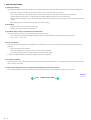
4-4 File Sort
Full pathnames ("/DCIM/100CANON") are sorted in alphabetical order.
If there are six directories; "/";"/CUSTOM";"/FREE";"/DCIM/100CANON";"/DCIM/101CANON";"/DC97/CTG_0020", they are sorted in the following order: "/" > "/CUSTOM" -> "/DC97/CTG_0020" -> "/DCIM/100CANON" -> "/DCIM/101CANON" -> "/FREE"I
<File name sorting specifications>
Files specified in the DCF (Design rule for Camera File system) standards (“the file name with 8 characters excluding the extensions, and with the latter 4-digit
figures”) are sorted to the top of the list by priority.
Also, DCF files are sorted using the last 4-digits, which are recognized as a number, and sorted in ascending order. For non- DCF files, if the file name includes
numbers, they are recognized as numbers, and are sorted in ascending order also.
Sorting is performed for each directory.
As the iP6000D can work with up to 999 files, the 1,000th file and later are not sorted.
Detailed sorting specifications are as follows:
File order is determined using the rules in the following order to sort from Low to High in ascending order:
A. When one is a DCF file, and the other is a non-DCF file, the DCF file is low.
eg. IMG_0001.JPG < IMG_FILE.JP
B. When both files are DCF files,
B-1. The last 4-digits (numbers) of each file name are recognized as a number, with the smaller number low. eg. IMG_0001.JPG < IMG_0002.JPG,
IMG_0005.JPG < 07240010.JPG (The latter figures are 0005 and 0010.)
B-2. When the result of the comparison in B-1 above is the same, the files are then sorted in alphabetical order. eg. ABC_0001.JPG < ABD_0001.JPG
IMG_0001.JPG < IMG_0001.TIF (J is "lower" than T.)
C. When both files are non-DCF files,
C-1. From the beginning of the file name, the position of first number is detected, sorting by distance in ascending order.. eg. IMG001.JPG < IMG_001.JPG
C-2. When the result of the comparison in C-1 above is the same, numbers are sorted in ascending order. eg. IMG001.JPG < ABC002.JPG
C-3. When the result of the comparison in C-2 above is the same, the length of the numerical string is sorted in ascending order. eg. IMG001.JPG <
ABC0001.JPG (The length of the former is 3, and the latter is 4.)
C-4. When the result of the comparison in C-3 above is the same, the next character is recognized as the top of the file name, and the process returns to C-1. eg.
A_1_2_.JPG < A_1_2_3.JPG (as the results of the comparison in the first (1) and second (2) loops are the same, in the third loop, the distance to the next number
is 0.)
C-5. When the result of repetition from C1 to C4 is the same, the files are sorted in alphabetical order, as in B-2. eg. A_1_2.JPG < A_1_2.TIF
4-5 Date Print
It is possible to print the date in the following three patterns, or to not print the date.
MM/DD/YYYY
DD/MM/YYYY
YYYY/MM/DD
However, in DPOF mode, the DPOF setting is used. For the date layout and size, refer to the print layout. The date data to be used in date print are as follows:
Print Mode
Exif file or non-Exif file
DPOF mode
Non-DPOF mode
--
Date data to be printed
Date in the DPOF file
Exif file: Creation date of the image data exists.
Date when the Exif file was created
Non-Exif file
Updated date of the file system
4-6 Bubble Jet Direct Function
The following applies when the printer is connected to a Bubble Jet Direct-supported digital camera. For PictBridge functionality, refer to 4.7 PictBridge Function.
4-6-1 Print mode
In Bubble Jet Direct, the following print modes are selectable.
Easy print: Printing of images during reproduction of single frame or index. Standard printing only.
DPOF print: Printing with DPOF printing settings. Standard and index printing can be set.
2-9
4-6-2 Media type
Media types that can be printed in the Digital Camera Direct Printing are as follows: When the language setting on the digital camera is not set to Japanese. (Media
types for overseas destinations are identical, however the panel display differs depending on the languages. The following is the display of US English.)
Paper setting in digital camera operation panel
iP6000D
Card#1
Photo Paper Pro 4" x 6" (PR-101 4" x 6")
Card#2
Photo Paper Plus 4" x 6" (PP-101 4" x 6")
Card#3
Photo Paper Plus 5" x 7" (PP-101 C 5" x 7")
LTR
Photo Paper Pro Letter (SP-101 LTR)
A4
Photo Paper Pro A4 (PR-101 A4)
When the language setting on the digital camera is set to Japanese.
Paper setting in digital camera operation panel
iP6000D
L
Photo Paper Plus L (SP-101 L)
2L
Photo Paper Plus 2L (SP-101 2L)
Postcard
Professional Photo postcard (PH-101)
A4
Photo Paper Plus A4 (SP-101)
Card*1
Professional Photo card (KM-101 and MM-101)
*1 Printing is possible only when feeding is performed from the sheet feeder.
4-6-3 Print layout
Print layout can be set to Border or Borderless in the digital camera operation panel
Easy print:
- Borderless: 1 photo
- Border:
1 photo
DPOF print
Standard:
- Borderless: 1 photo
- Border:
1 photo
Index Print:
- Same as Index mode of Memory Card Direct Printing.
4-6-4 Print quality
No. of passes: 8 passes
Resolution:
Bk, Y, M, C, PM, PC: 4,800 dpi x 1,200 dpi
Bk/Y:
5 pl
M/C/PM/PC:
5 pl /2 pl (mixed)
4-6-5 Image correction function
Exif 2.2 files are processed with APP (Auto Photo Perfect), and for other files, image correction is not implemented.
Not selectable by users.
4-6-6 Maintenance
Maintenance operation of the iP6000D via the digital camera's operation panel is not possible. Maintenance operations are possible through the operation panel of
the iP6000D printer even when connected to a digital camera.
4-6-7 Print date
Dates can be printed by switching the date setting on the digital camera's operation panel to "ON".
Dates cannot be printed in index printing of DPOF print mode.
4-6-8 Copies
The number of prints can be specified in both Easy Print and DPOF Print modes via the digital camera's operation panel.
To the top
<2-4. PHOTO DIRECT PRINT FUNCTION (4)~(6)>
2 - 10
4-7 PictBridge Function
The following applies when the printer is connected to a PictBridge-supported digital camera.
(As PictBridge is enabled when both the printer and digital camera have shared functionality, some functions may not be selectable, depending on the combination of
the printer and digital camera.)
For Bubble Jet Direct functionality, refer to 4.6 Bubble Jet Direct Function.
For other companies' digital cameras, refer to the camera's manual.
4-7-1 Print mode
In a PictBridge-supported digital camera, only the single frame reproduction print mode is selectable.
4-7-2 Media type
Media types that can be printed in the Digital Camera Direct Printing are as follows:
Paper setting in digital camera operation panel
iP6000D
Default
Depending on the printer setting
Photo
Photo Paper Plus Glossy
Fast Photo
Photo Paper Pro
4-7-3 Print layout
Print layout can be set to Border or Borderless in the digital camera operation panel.
However, borderless printing with plain paper cannot be performed.
4-7-4 Print quality
Print quality can be set to Standard or High.
For resolution by each print mode, refer to 3. PRINT MODE.
4-7-5 Image correction function
The following four correction functions may not be selectable by users, in some cases.
APP:
ON/OFF
Viv
id Photo:
ON/OFF
Noise reduction: ON/OFF
Face brightener: ON/OFF
4-7-6 Image adjustment
Brightness: -2, -1, standard, +1, +2
Contrast:
-2, -1, standard, +1, +2
Color hue:
Skin color red+2, red+1, non-adjustment, yellow+1, yellow+2
4-7-7 Image processing
Sepia
Simulate illustration
Non-processing
4-7-8 Maintenance
Maintenance operation of the iP6000D via the digital camera's operation panel is not possible.
Maintenance operations are possible through the operation panel of the iP6000D printer even when connected to the digital camera.
4-7-9 Print date
Dates can be printed by switching the date setting on the digital camera's operation panel to "ON"
4-7-10 Copies
The number of prints can be specified via the digital camera's operation panel
4-7-11 Digital camera's standard setting
For PictBridge-supported digital cameras, the Standard Setting is selectable in the following settings:
(When Standard Setting can be selected, printing will be performed using the printer's settings.)
Possible Standard Setting
Dependency on the printer
Setting at Printer Shipment
Paper size
Depending on the printer setting
L size
Paper type
Depending on the printer setting
Photo Paper Plus Glossy
Layout
Depending on the printer setting
Borderless
Image correction
Depending on the printer setting
Exif Print
Print date
Depending on the digital camera
Date not printed
2 - 11
4-8 Exclusive Processes
4-8-1 Exclusive processes in Memory Card Direct Printing and Digital Camera Direct Printing
As it is impossible to simultaneously process Memory Card Direct Printing and Digital Camera Direct Printing, the following actions are taken:
When the digital camera is connected via the digital camera connection cable:
Memory Card Direct Printing settings and operation are not possible.
Setting items are not displayed in the operation panel, and the print start button is invalid.
"Digital camera connected." is displayed on the LCD viewer.
When direct printing from the memory card:
Digital Camera Direct Printing is impossible. (Settings in the digital camera are possible.)
If Digital Camera Direct Printing print operations are attempted, an error is displayed in the digital camera.
4-8-2 Exclusive process control between direct printing and printing from the host computer
As it is impossible to simultaneously process direct printing from memory cards or digital cameras and printing from the host computer, the following actions are
taken:
When printing from the host computer:
Memory Card Direct Printing and Digital Camera Direct Printing are impossible.
When printing via Memory Card Direct Printing and Digital Camera Direct Printing:
Printing from the host computer is impossible.
4-8-3 Exclusive processes in host computer memory card access and Memory Card Direct Printing
Writing of data from the host computer to the memory card, while reading image data from the memory card for direct printing is conducted as follows in order to
avoid overwriting the image being printed in Memory Card Direct Printing, via the host computer.
When direct printing from the memory card:
Writing data from the host computer to the memory card is not possible. (Reading of data is possible.)
An error is displayed in the host computer at the start of data writing operations.
When writing data from the host computer to the memory card*
Direct printing from the memory card is not possible.
Even if the print start button is pressed, printing will not start.
*To write data from the host computer to the memory card, the mode needs to be changed to the Read/write mode, using the Memory Card Utility.
4-8-4 Exclusive processes between the memory card and memory card
In the card slot, there is a slot for SM, MS, and SD/MMC (used in common, however, multiple cards can not be inserted simultaneously) and a slot for a CF card.
However, even though a CF card and other card are inserted simultaneously, as one drive only is always valid, control are performed as follows:
The card inserted first has priority. Even if a card is inserted into a drive other than the current drive, this action is ignored.
When the current drive is removed, the other drive is checked. If a card is detected, the same control as when the former card is removed and a new card is inserted,
is performed.
When multiple cards are inserted when the printer is powered on, the drive is checked in the order of CF, SM, MS, and SD/MMC, and the drive in which a valid card
is detected becomes the current drive.
When the memory card is uninstalled from a computer, the power supply for the card with the current drive is halted, and the no card inserted status is valid.
However, as long as the card is not removed from the current drive, even though another card is inserted into another drive, this action is ignored.
4-9 LCD Viewer
The iP6000D LCD viewer is a 2.5 inch (176 x 128 pixel, 65,000 colors) color LCD, and realizes two functions: image display and operation display with the
operation panel. Operations are carried out by the user selecting the desired menu item from within a nested menu displayed on the LCD viewer, and by pressing the
OK button, proceeding with the next step. During the process, if an image needs to be selected, it can be displayed on the LCD viewer, and the selected image can be
changed by using the left and right cursor buttons.
To protect the LCD viewer and preserve the backlight life, when no button operation has occurred for five minutes, the LCD viewer is powered off. When any key
other than the Power and Resume buttons and Paper Feed switch is pressed with the LCD backlight off, the LCD viewer turns on, however the original function of
the key is invalid.
The content displayed on the LCD viewer changes depending on the user's operation.
Eg. When printing is being performed from the PC, the LCD viewer displays "Printing from the computer", when a digital camera is connected, the LCD shows the
printer status by displaying "Digital camera connected", and when an error occurs during printing, such as the paper out error, the LCD shows the error by displaying
"No paper. Load paper and press Resume".
When Card Direct Printing is performed, the LCD viewer becomes the operation display of the operation panel.
2 - 12
4-10 Card Slot-related Operations and Display
4-10-1 Timing and precautions when removing the memory card
The following timing and precautions are suggested to protect the memory card data.
- Remove the memory card while the Access lamp is not lit. (If the memory card is removed while the Access lamp is blinking or on, the data on the card is not
assured.)
- When the printer is not connected to a host computer, power off the printer with the Power button and after the Access lamp is not lit, remove the memory card.
- Remove the memory card together with the adapter, not the memory card only.
- When the printer is connected to the host computer, from the host computer, select "Eject disk" to turn the Access lamp off, and then remove the memory card.
(Turning off the printer also turns off the Access lamp, however, the incorrect disk removal warning message may be displayed in the connected host computer.)
When using Windows, and the memory card drive is displayed in Explorer, close the window prior to removing the memory card. (If the window is not closed
prior to removing the memory card, the following phenomenon will appear in the host computer.)
WindowsMe/98:
A blue background screen appears. This can be recovered by following the instructions in the display.
Windows2000/XP: A warning is displayed, and the "Eject disk" operation cannot be executed.
4-10-2 Power supply/cut to the memory card
1) Power supply to the memory card
When any of the following events occurs, the memory card detection process starts, and if an accessible memory card is recognized, power supply to the memory
card starts. (The Access lamp lights.)
a. When a memory card is inserted into the card slot while the printer is on.
b. When the printer is powered on while a memory card is in the card slot.
c. When the USB bus is reset while the printer is on with a memory card in the card slot. (When the host computer is already on, and is connected to the printer
via USB, or when the host computer is restarted.)
2) Power cut to the memory card
When any of the following events occur, power supply to the memory card is cut. (The Access lamp turns off.)
a. When the printer is turned off by pressing the Power button.
However, power is supplied in the following instances even if the printer is not on:
- From the time that a memory card not-removable command is received from the host computer until a removal permission command is received, or the USB
cable is disconnected.
- From the time that a writing command is received from the host computer to the memory card until writing is completed.
b. When the memory card is removed from the card slot by pressing the Eject Button.
c. When the following "Memory card removal command" is implemented on the connected host computer.
4-10-3 Memory card removal command from the host computer
When the following operation is performed on the host computer, it is detected that the memory card removal command has been implemented, and power supply to
the memory card is cut.
Select "Change the driver's read/write attribute" in the Memory Card Startup Utility.
To the top
<2-4. PHOTO DIRECT PRINT FUNCTION (7)~(10)>
2 - 13
4-11 DPOF Settings in the Memory Card Direct Printing Function
4-11-1 Supported DPOF functions
DPOF Ver. 1.0 is supported.
The following essential functions as a DPOF printer are supported.
- Standard printing
- No. of copies to be printed (1 page)
- Image format (CIFF, EXIF (JPEG), JFIF)
- Designation of images to be printed (relative path name)
The following optional functions as a DPOF printer are supported.
- Index printing
- No. of copies to be printed (2 pages or more)
- Image format (EXIF (TIFF)) - Printing of designated characters (dates, photo numbers)
If both dates and photo numbers are selected, one of the two will be printed.
Note: The CMT value indicating the comment and image title is not supported.
The following optional functions as a DPOF printer are not supported.
- Image format (FlashPix)
- Designation of paper types
- Trimming
- Rotation of images
4-11-2 Print specifications in DPOF print mode
Photo number designation:
Only photos designated in the DPOF file can be printed, and designation via the operation panel is impossible.
Paper type:
The paper type can be selected from the operation panel.
Layout:
Images designated for Standard printing in the DPOF file are printed in the designated order in the layout designated through the operation panel.
Images designated for index printing will be printed using the printer's index layout, regardless of the specified layout.
No. of copies to be printed:
The number of copies cannot be designated from the operation panel. Only the number of copies designated in the DPOF file is printed.
Image correction:
Automatic image correction can be designated from the operation panel.
Quality:
The print quality can be designated from the operation panel.
Date print:
Date print cannot be designated from the operation panel in DPOF mode, and printing is implemented using the file's DPOF settings.
Date formats are dependent on the digital camera.
4-12 Print Layout (Details)
4-12-1 Selectable layout in Memory Card Direct Printing
<Overseas>
- Index printing
LTR/A4: 80 photos, 4" x 6": 24 photos, 5" x 7": 35 photos
- Layout printing
2/4/8 photos with borderless/bordered (LTR, A4*1, 4" x 6", 5" x 7")
Postcard (with ruled line) with borderless/bordered (LTR, A4*1, 4" x 6", 5" x 7")
Album 4 photos with either side (LTR, A4*1, 4" x 6", 5" x 7")
Mix three types (LTR, A4)
- Single frame printing (= single image / page)
A4/LTR with borderless*1/bordered, 4" x 6" with borderless/bordered, 5" x 7" with borderless/bordered
2 - 14
<Japan>
- Index printing
L: 15 photos, 2L: 35 photos, Post card: 24 photos, A4: 80 photos, LTR/A4: 80 photos, Name card/Card: 6 photos*2, Panorama: 30 photos)
- Layout printing
2/4/8 photos with borderless/bordered (L, 2L, Post card, A4*1, Panorama, Name card/Card*2)
Postcard (with ruled line) with borderless/bordered (L, 2L, Post card, A4*1, Panorama, Name card/Card*2)
Album 4 photos with either side (L, 2L, Post card, A4*1, Panorama, Name card/Card*2)
Mix three types (A4)
- Photo Stickers*2
2/4/9/16 seals
1/5/6/7 seals (for free-cut)
- Single frame printing (= single image / page)
L with borderless/bordered, 2 L with borderless/bordered, Post card with borderless/bordered, A4 with borderless*1 /bordered, and Name card / Card*2 with
borderless/bordered
*1 Plain paper is not selectable.
*2 Printing is possible only when paper feeding is performed from the sheet feeder.
4-12-2 Selectable layout in Digital Camera Direct Printing
When the language setting on the digital camera is not set to Japanese.
(Media types for overseas are common for all markets, however the panel display differs depending on the languages.
The following is the display of US English.)
- Index printing
LTR/A4: 80 photos, 4" x 6": 24 photos, 5" x 7": 35 photos
- Single frame printing
A4/LTR with borderless/bordered, 4" x 6" with borderless/bordered, 5" x 7" with borderless/bordered
When the language setting on the digital camera is set to Japanese
- Index printing
L: 15 photos, 2L: 35 photos, Post card: 24 photos, A4: 80 photos, Name card/Card: 6 photos*1
- Single frame printing
L with borderless/bordered, 2 L with borderless/bordered, Post card with borderless/bordered, A4 with borderless*2/bordered, Panorama with
borderless/bordered, Name card/Card*1 with borderless/bordered
*1 Printing is possible only when paper feeding is performed from the sheet feeder.
*2 Plain paper is not selectable.
4-12-3 Layout in Memory Card Direct Printing
Layout of multiple images is arranged as shown below.
- Images are arranged horizontally, from left to right, top to bottom.
- When the number of photos designated requires less space than the layout provides, nothing is printed in the remaining spaces.
2 - 15
4-12-4 Layout and image size
Processing in borderless printing (including 2 photos / 4 photos / 8 photos / postcard with borderless)
1) Rotate the image data by 90 degrees (if necessary) to align the long edges of the image with those of the paper.
2) Enlarge (or reduce) the image data while maintaining the image's proportions so as to align either the long or short edges of the image with those of the paper , so
that blank space in the paper is completely eliminated.
3) Any image data extending beyond the printing area will be cut off and not printed. (The discarded image data will be equally divided between top and bottom, or
left and right.)
Note: As printing of the image is performed to an area 5 mm larger than that of the paper size, the perimeter of the image is further trimmed by a few
millimeters.
Processing in printing in print area without image trimming
1) Rotate the image data by 90 degrees (if necessary) to align the long edge of the image data with that of the paper.
2) Enlarge (or reduce) the image data while maintaining the image's proportions so as to align either the long or short edges of the image with those of the print area
(blue line), so that no image data is discarded.
3) The area without any image data will be blank. (Empty areas will be equally divided between left and right, or top and bottom.)
To the top
<2-4. PHOTO DIRECT PRINT FUNCTION (11)~(12)>
2 - 16
4-13 Date Print Specifications
4-13-1 Date print in Memory Card Direct Printing
1) Settings and data format
Printing in DPOF (Index and Standard) mode:
When date print is set to ON in the DPOF settings, the date is printed using the character strings in the DPOF settings, regardless of the date setting in the
printer's operation panel.
The number of characters: Up to 24 (for Standard) / Up to 12 (for Index)
Printing in other modes:
When the date setting is selected from the Date tab in Settings on the operation panel, the Exif tag information in the file is printed in the following order:
Year (four digits), month (two digits), and date (two digits), with date elements separated by "/".
If the Exif tag information does not exit, or does not have correct information, Use the date when the file was updated.
Ex. 1999/06/30 06/30/1999
2) Print location, color and size
Index mode
Printing in Index mode:
Location: Below the image (under the photo number)
Color: Black
Size: Fixed size
001 100-0001
1999/06/30
Printing in DPOF (Index) mode:
DPOF
Location: Below the image
Color: Black
Size: Fixed size
1999/06/30
Printing in DPOF (Standard) and other modes:
Location: Lower right, in the image (In images with an aspect ratio other than 4:3, the date is moved such that the relative distance from the lower right to the
image date is the same as when a 4:3 ratio is used.)
Color: Orange
Size: According to the layout
Example 1
Example 2
4-13-2 Date print in Digital Camera Direct Printing
1) Settings and data format
When date print is set in the digital camera, the date is printed using the character strings sent by the digital camera. However, in Bubble Jet Direct index
printing using the digital camera, the date will not be printed, regardless of the settings.
2) Print location, color and size
Printing in easy print and DPOF (Standard) modes:
Location: Lower right, in the image (In images with an aspect ratio other than 4:3, the date is moved such that the relative distance from the lower right to the
image date is the
same as when a 4:3 ratio is used.)
Color: Orange
Size: According to the layout
Example
Printing in DPOF (Index) mode:DPOF
Date is not printed, even when set in the digital camera's DPOF settings.
2 - 17
4-14 Photo Number Printing Specifications
4-14-1 Photo number printing in Memory Card Direct Printing
1) Data format
Printing in Index mode:
Photo number (3-digit number) and DCF number (8-character number (***-****) displayed on the operation panel) are printed. (Printed without exception)
Printed characters consist of 3 characters + space + 8 characters.
Printing in DPOF (Index and Standard) mode:
When the file number print is set to ON in the DPOF settings, the file number character string set in the DPOF settings is printed, as is. (However, when date
print is selected, the file number will not be printed.)
The number of characters: Up to 24 (for Standard)
Up to 12 (for Index))
Printing in other modes:
The photo number will not be printed.
Printing in Index mode:
Index mode Index printing
Location: Below the image (Above the date)
Color: Black
Size: Fixed size
001 100-0001
1999/06/30
Printing in DPOF (Index) mode:
DPOF mode Index printing
Location: Below the image
Color: Black
Size: Fixed size
100-0001
Printing in DPOF (Standard) mode:
Location: Lower right, in the image (In images with an aspect ratio other than 4:3, the photo number is moved such that the relative distance from the
lower right to the image photo number is the same as when a 4:3 ratio is used.)
Color: Orange
DPOF mode Standard printing
Size: According to the layout
Printing Printing in other modes:
The photo number will not be printed.
4-14-2 Photo number printing in Digital Camera Direct Printing
1) Data format
The photo number will not be printed, even when set in the DPOF settings.a)
2) Print location, color and size
The photo number will not be printed.
To the top
<2-4. PHOTO DIRECT PRINT FUNCTION (13)~(14)>
2 - 18
5. FAQ (Problems Specific to the iP6000D and Corrective Actions)
No.
*
Function
Phenomenon
Margin (approx.
0.3mm)
1
C
Print results
Condition
Cause
- Paper feeding from the
cassette, Photo Paper Plus
Double Sided (A4),
borderless printing,
printing on the back side
of paper
Corrective action
Possible call or
complaint
- In the printer driver, increase
the amount of extension.
- A margin appears on
printouts.
- Change the paper feeding
method from the cassette to
the auto sheet feeder.
- Paper feeds at an
angle.
- In the low temperature and
low humidity
environment
- Skewed paper
feeding
2
B
Print results
- Printing on the
platen
- Plain paper
- If paper is curled, straighten it. - Paper feeds at an
angle.
- Try printing on the other side
- In the high temperature
and high humidity
environment
of paper.
- Printing is performed
on the platen.
- The back side of
paper gets smeared.
3
4
5
B
B
C
Print results
Print results
Safety during
transportation
Variation in the top - A5 or legal size
of form accuracy
- In the low temperature and
low humidity
environment
A
Print results
- Skewed paper
feeding
- Photo Paper Plus Double
Sided
- In the printer driver, increase
the amount of extension.
- A margin appears on
printouts.
- Margin
- 2L size (Japan only)
- Change the paper feeding
method from the cassette to
the sheet feeder.
- Paper feeds at an
angle.
Carriage lock lever
dislocation
- With the print head and
ink tanks installed
When returning the repaired
printer to the user, insert the
fixing tool (A4 plain paper
folded 5 times) between the
main case and the carriage, and
fix it with tape. [See Part 1, 4.
PRINTER
TRANSPORTATION]
During transportation
for return after repair,
Ink dries, and no ink is
ejected.
- The phenomenon occurred
in the freight handling
test.
- With Photo Paper Plus
Double Sided or
postcards, the
phenomenon is likely to
be noticeable and to be
complained of by users,
as printing is performed
on both sides of such
paper.
Soiling on paper in - Automatic duplex printing
automatic duplex
(Photo Paper Plus Double
printing (lines or
Sided, postcards, plain
streaks
paper)
perpendicular to the
paper feed
direction)
In borderless printing,
1. Perform Bottom plate
printing is performed to
cleaning (from the printer
the size slightly larger
driver) up to 3 times*1.
than the paper size, and *1
: Change the paper in each
ink off the paper is
Bottom plate cleaning.
absorbed by the platen's
The cleaning can end
ink absorber. Absorbed
when paper does not get
ink may attach to the
any soiling.
platen rib(s) after several
dozen sheets are printed, 2. If soiling on the paper still
causing soiling at the
remains after 3 times of
leading edge of paper or
Bottom plate cleaning,
on the back side of
wipe the platen rib(s) and
paper.
their surroundings with a
cotton swab.
- Paper gets smeared.
On the rib(s) inside the
sheet feed unit used for
duplex printing, ink mist
may accumulate,
smearing paper.
- Paper gets smeared.
Temporary operational
solution:
Cancel automatic duplex
printing, and manually print
each side of paper.
Cleaning by user:
7
B
Print results
1. Perform Bottom plate
cleaning (from the printer
driver) up to 3 times*1.
*1:
Change the paper in each
Bottom plate cleaning.
The cleaning can end
when paper does not get
any soiling.
2. If soiling on the paper still
remains after 3 times of
Bottom plate cleaning,
wipe the platen rib(s) and
their surroundings with a
2 - 19
- Print start position
varies.
- Not solved even when the
number of sheets stacked
in the auto sheet feeder or
the cassette is reduced
Soiling on the back - After continuous
side of paper (lines
borderless printing of
or streaks parallel to
small sized paper (such as
the paper feed
4 x 6), when a larger
direction)
sized paper (such as A4)
is printed.
6
Due to decrease of paper - Set the top margin to 4mm or
feed capability in the low
more.
temperature and low
humidity environment
- The back side of
paper gets smeared.
- The back side of
paper gets smeared.
- Even after Bottom
plate cleaning was
performed, and the
platen ribs were
cleaned with cotton
swab, paper gets
smeared.
cotton swab.
If the phenomenon persists after
conducting 1 and 2, servicing is
required.
Service:
Wipe any soiling or dirt off
from the sheet feed unit and the
bottom case unit ribs*2.
Scratches on paper
8
C
- PP-101D, PP-101, PR101, SG-101, etc.
- Paper feeding from the
cassette
Print results
B
Paper is curled
Credit/name card sized paper can not
be ejected.
-
Print result
-
Scratches on the PF
return lever due to
paper feeding from the
- If automatic duplex printing is cassette, and duplex
performed, cancel it, and, by printing path.
setting only a single sheet of
paper in the auto sheet feeder,
manually print each side of
paper.
- Widen space between paper
and paper
Paper is soiled.
- Flatten paper
- KM-101, MM-101
Paper is set sideways in
the sheet feeder.
- GP-401 Credit Card
To change color
hue at Direct Print,
as color hue is redtinged.
At Direct Print
Set paper vertically in the sheet Paper is not ejected.
feeder.
'This paper size can be fed by
setting paper vertically in the
sheet feeder. Feeding through
the cassette is not possible.)
(specifications)
11
- Change the paper feeding
method from the cassette to
the sheet feeder.
- PR-101 (L, 4" x 6")
Print results
Paper feeding
10
- Marks appear on
printed paper.
- Multiple number of sheets
loaded
Soiling on the print - PSHR, KM-101
surface of a page
9
- Paper is scratched.
Color hue is different
from the desired colors.
Perform color adjustment on the Color hue is not
operation panel.
normal.
(specifications)
*1: When paper is not soiled, cleaning is complete. Change paper each time cleaning is performed.
*2: Locations to clean in servicing when soiling on paper in automatic duplex printing persists:
* Occurrence level:
A: The symptom is likely to occur frequently. (Caution required)
B: The symptom may occur under certain conditions, but likeliness is assumed very low in practical usage.
C: The symptom is unlikely to be recognized by the user, and no practical issues are assumed.
To the top
<Part 2: 5. FAQ>
2 - 20
6. PIXMA iP6000D Specifications
<Printer>
Type
Desktop serial color bubble jet printer
Paper feeding method
Auto sheet feed (sheet feeder, cassette, automatic duplex printing, CD-R printing*1)
Resolution
4,800 dpi x 1,200 dpi (Max.)
Throughput
(Target value)
Draft
Standard
BK (Fine Black)
11 ppm
4.3 ppm
Color (Fine Color)
9 ppm
3.0 ppm
Printing direction
Bidirectional, uni-directional
Print width
Max. 203.2 mm (216 mm in borderless printing)
Interface
USB 2.0 Full Speed, Camera Direct Print Port, IrDA 1.2 (supports only JPEG files)
ASF stacking capacity
Plain paper (65 g/m2): Max. 13 mm (Approx. 150 sheets)
Paper weight
64~105g/m2
Detection functions
Acoustic noise
(Highest print quality)
-Cover open
-Presence of print head
-Remaining ink amount (optical / dot count)
-Printing position
-Paper presence
-Paper end sensor
-Waste ink amount
-Internal temperature
-Pick-up roller
-Paper feed roller position
-Carriage position
-Head-to-paper distance
-Supported camera direct printing device
-Presence of CD-R
-Supported paper size for duplex printing
-Presence of memory card
- Highest print quality settings: Approx. 35 dB
- Quiet mode:
Approx. 32 dB
During operation
Environmental requirements
Non operation
Power supply
Temperature
5C to 35C (41F to 95F)
Humidity
10%RH to 90%RH (no condensation)
Temperature
0C to 40C (32F to 104F)
Humidity
5%RH to 95%RH (no condensation)
Power supply voltage, frequency
Power consumption
Standby
Power-off
AC 110 to 120 V, 50/60Hz
Approx. 15 W
Approx. 3 W
Approx. 1 W
AC 220 to 240 V, 50/60Hz
Approx. 15 W
Approx. 3 W
Approx. 1 W
Printer:
External dimensions
With the paper support and output tray retracted:
Approx. 429 (W) x 312 (D) x 195 (H) mm
With the paper support and output tray extended:
Approx. 429 (W) x 548 (D) x 323 (H) mm
Weight
Approx. 7.0 kg, not including print head and optional units
Related standards
(Proposed)
(Printer, Adapter)
Electromagnetic radiance:
VCCI, FCC, IC, CE Mark, Taiwan RPC, C-Tick, CCC (EMC), Korea MIC, Gost-R
Electrical safety:
Electrical Appliance and Material Safety Law (DENAN), UL, C-UL, CB Report, CE Mark, GS, Gost-R, FT, SASO,
CCC, SPRING, Korea EK, IRAM (Argentine)
Environmental regulations:
RoHS (EU), WEEE (EU), Korea Package Recycle Law, Green Point (Germany), Energy Star, Eco Mark, Law on
Promoting Green Purchasing
Serial number location
On the carriage flexible cable holder (visible when the access cover is open).
Remaining ink amount detection
Available (automatic detection by optical method and dot count, enabled at default)
Paper type detection
Not available
Print head alignment
Available (automatic or manual alignment via the driver utility (automatic alignment at default) or the operation panel on
the printer in Camera Direct Printing)
*1: Only for CD-R printing supported regions
<Photo Direct Printing>
Memory card drive
Storage function
Supported memory card
Compact Flash Type I/II, Microdrive, SmartMedia Card, Memory Stick, Memory Stick PRO,
MagicGate Memory Stick, SD Card, MultiMedia Card, xD-Picture Card*, miniSD memory card*,
Memory Stick Duo*, Memory Stick PRO Duo*, MagicGate Memory Stick Duo*
Supported OS
Windows Me / 98 / 2000 / XP
Mac OS 9.x/10.2.1 or later
Utility
Function
3 - 10
Storage utility packaged with printer
Read / Write
Direct memory card print
function
Operation panel
2.5 Color LCD, 19 keys
File format
JPEG (DCF, CIFF, Exif 2.2 or prior, JFIF), TIFF (Exif compliant), DPOF compliant
Supported print paper
[See 3-4. Print Media Specifications]
Print quality
Image quality/speed prioritized
Image correction function
APP, VIVID, image noise reduction, Face brightener
Image adjustment function Brightness, contrast, hue (flesh color)
Image processing function Sepia and illustrated touch
Image retrieval function
Available (date)
DPOF version
Ver. 1.00 compliant
- Image/image specification/full-image printing:
1 page (bordered/borderless *only bordered for plain paper)
- DPOF printing:
1 page (bordered/borderless)
6, 15, 24, 35, 80 images
Print layout
- Index printing:
6, 15, 24, 35, 80 images
- Layout printing:
2, 4, 8 images (bordered/borderless)
Mix 3 types (for A4/LTR)
- Photo Stickers:
2, 4, 9, 16 seals
1, 5, 6, 7 seals (for free-cut)
Direct camera print
function
Resolution
Max. 1,200 x 1,200 dpi
Throughput
Approx. 1 minutes 50 seconds, with the following conditions and settings:
- Image data from a 3 mega-pixel digital camera
- Process from pressing the printing start button to ejecting paper
Supported digital cameras
Digital cameras and digital video cameras supporting Bubble Jet Direct or PictBridge
Supported print paper
[See 3-4. Print Media Specifications]
Print layout
- 1 paper (bordered/borderless)
- Index printing: 2, 4, 9, 16 images (bordered)
Resolution
Max. 1,200 x 1,200 dpi
Throughput
Approx. 1 minute and 50 seconds, with the following conditions and settings:
- Image data from a 3 mega-pixel digital camera
- Process from pressing the printing start button to ejecting paper
<Print Head>
Print head
Type
Single head with 6 removable ink tanks (each color)
Print head
BK/Y:
256 nozzles per color (128 nozzles in 2 vertical lines (5 pl), 1,200dpi
C/M/PC/PM: 128 nozzles per color (5 pl) + 128 nozzles per color (2pl), 1,200 dpi
5 pl (black, yellow, cyan, magenta, photo cyan, photo magenta)
2 pl (cyan, magenta, photo cyan, photo magenta)
Ink color
Dye-based black, cyan, magenta, yellow, photo cyan, photo magenta
Ink tank
BCI-6 BK/C/M/Y/PC/PM
Weight (Net)
Print head, approx. 62 g
Ink tanks (6 colors), approx. 168 g
Supply method
As a service part (not including ink tanks)
Part number
QY6-0050-000
To the top
<PIXMA iP6000D SPECIFICATIONS>
3 - 11
4. Print Media Specifications
(1) Plain paper / specialty paper
The following types of paper are recommended:
Type
Name
Plain paper
(64 to 105 g/m2)
Size
Paper feeding
method
ASF stacking
capacity (max.)
A4, LTR
ASF, Cassette
13 mm
B5, A5, LGL
ASF, Cassette
13 mm
Camera
Direct
Printing
Card Direct
Printing
Print
Beam
Yes
Yes
Super White Paper
SW-201
A4, LTR
ASF, Cassette
13 mm
High Resolution Paper
HR-101N
A4, LTR
ASF, Cassette
80 sheets
Yes
Yes
GP-401
A4, LTR
ASF, Cassette
10 sheets
Yes
Yes
Yes
GP-401 4x6
101.6 x 152.4 mm
ASF, Cassette
20 sheets
Yes
Yes
Yes
GP-401 Credit Card
54 x 86 mm
ASF
20 sheets
Yes*1
Yes
Yes
PR-101
A4, LTR
ASF, Cassette
10 sheets
Yes
Yes
Yes
PR-101 4x6
101.6 x 152.4 mm
ASF, Cassette
20 sheets
Yes
Yes
Yes
PP-101
A4, LTR
ASF, Cassette
10 sheets
Yes
Yes
Yes
PP-101 4x6
101.6 x 152.4 mm
ASF, Cassette
20 sheets
Yes
Yes
Yes
PP-101 5x7
127 x 178 mm
ASF, Cassette
10 sheets
Yes
Yes
Yes
MP-101
A4, LTR
ASF, Cassette
10 sheets
Yes
Yes
SG-101
A4, LTR
ASF, Cassette
10 sheets
Yes
Yes
Yes
SG-101 4x6
101.6 x 152.4 mm
ASF, Cassette
20 sheets
Yes
Yes
Yes
PP-101D
A4, LTR
ASF, Cassette
10 sheets
Yes*1
Yes
Yes
Glossy Photo Paper
Photo Paper Pro
Photo Paper Plus Glossy
Matte Photo Paper
Photo Paper Plus Semi-gloss
Photo Paper Plus Double Sided
PP-101D 5x7
127 x 178 mm
ASF, Cassette
10 sheets
Transparency
CF-102
A4, LTR
ASF, Cassette
30 sheets
T-shirt transfer
TR-301
A4
ASF, Cassette
1 sheet
Photo Stickers
PS-101
148 x 100 mm
ASF
1 sheet
COM#10
241 x 106 mm
ASF, Cassette
10, 5 envelopes
DL-size
220 x 110 mm
ASF, Cassette
10, 5 envelopes
Envelope
*1: Supported only by PictBridge (not supported by Bubble Jet Direct)
To the top
<3-4. PRINT MEDIA SPECIFICATIONS>
3 - 12