1
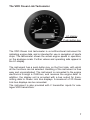
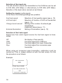
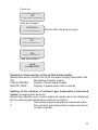
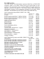
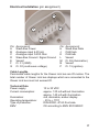
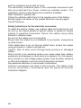
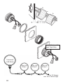
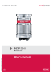
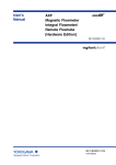
Handling a complex world. Installation and Operating Instructions Tachometer CAN Master Easy Link Gauge Installation and Operating Instructions 2 Contents Tachometer CAN Master Preliminary Remarks . . . . . . . . . . . . . . . . . . . . . . . . . . . . . . . . . 4 Safety Instructions . . . . . . . . . . . . . . . . . . . . . . . . . . . . . . . . . 5 ...for assembly . . . . . . . . . . . . . . . . . . . . . . . . . . . . . . . . . 5 ...for maintenance . . . . . . . . . . . . . . . . . . . . . . . . . . . . . . 6 The VDO Ocean Link Tachometer . . . . . . . . . . . . . . . . . . . . . 7 Components. . . . . . . . . . . . . . . . . . . . . . . . . . . . . . . . . . . . . . . 8 Accessories . . . . . . . . . . . . . . . . . . . . . . . . . . . . . . . . . . . 8 Functions of the VDO Ocean Link Tachometer . . . . . . . . . . 8 Displays and Setting Possibilities . . . . . . . . . . . . . . . . . . . . . 9 Basic Settings . . . . . . . . . . . . . . . . . . . . . . . . . . . . . . . . . . . . . 9 Selection of display units . . . . . . . . . . . . . . . . . . . . . . . . . 9 Selection of the baud rate . . . . . . . . . . . . . . . . . . . . . . . 10 Setting the inputs (config inputs) . . . . . . . . . . . . . . . . . . 10 Selection of fuel tank signal . . . . . . . . . . . . . . . . . . . . . . 10 Selection of the function of the 4-20 mA transmitter. . . . 11 Setting of the number of exhaust gas temperature measured values (change boost amount) . . . . . . . . . . . 11 Setting the illumination (external illumination) . . . . . . . . 12 Selection of the displays (screens on/off) . . . . . . . . . . . 12 Activation of the simulation mode . . . . . . . . . . . . . . . . . 12 Exit setup . . . . . . . . . . . . . . . . . . . . . . . . . . . . . . . . . . . . 13 Main Functions . . . . . . . . . . . . . . . . . . . . . . . . . . . . . . . . . . . 13 The CAN Interface . . . . . . . . . . . . . . . . . . . . . . . . . . . . . . . . . 14 Installation of the VDO Ocean Link Tachometer . . . . . . . . 15 Electrical Installation. . . . . . . . . . . . . . . . . . . . . . . . . . . . . . . 17 Cable Lengths . . . . . . . . . . . . . . . . . . . . . . . . . . . . . . . . . . . . 17 Technical Data . . . . . . . . . . . . . . . . . . . . . . . . . . . . . . . . . . . . 17 Easy Link Gauge Safety Instructions . . . . . . . . . . . . . . . . . . . . . . . . . . . . . . . . 19 ...for assembly . . . . . . . . . . . . . . . . . . . . . . . . . . . . . . . . 19 ...for the electrical connection . . . . . . . . . . . . . . . . . . . . 20 Components. . . . . . . . . . . . . . . . . . . . . . . . . . . . . . . . . . . . . . 21 Installation . . . . . . . . . . . . . . . . . . . . . . . . . . . . . . . . . . . . . . . 21 3 Tachometer CAN Master Preliminary Remarks In purchasing an instrument from the VDO marine range you have decided on a high value product, which has been manufactured according to acknowledged technical standards. Modern production processes and compliance with currently applicable quality assurance standards guarantee that our products leave the works in perfect condition. We thank you for making a good choice, and we are convinced that this instrument will be of great help to you and keep you safe at sea. In order to ensure easy and safe handling of your VDO tachometer, you should familiarize yourself with all the functions of the instrument. Please take the time to read these instructions carefully and completely. © Copyright by Siemens VDO Trading GmbH 2002 All rights reserved 4 Safety Instructions Please follow all the instructions given in this handbook exactly. Use of the instrument does not release you from the responsibility over your ship, and demands good seamanship. Always use your nautical experience in interpreting the displayed values. Safety Instructions for Assembly: You should have the tachometer installed by your shipyard, or by a specialised expert. If you carry out this work yourself, wear suitable working clothes. Do not wear wide fitting clothes. If you have long hair, wear a hair-net. Clothes and hair can get caught in moving and rotating parts. Wearing of metallic or conductive jewellery, such as necklaces, bracelets, rings etc is not allowed when working on the electrical installation on board. Before beginning work the minus pole of the battery should be disconnected, since otherwise there is a danger of short circuiting. Short circuits can cause cable fires, battery explosions and damage to other electronic systems. Please note that when disconnecting the battery, all volatile electronic memories lose their inputted values and must be reprogrammed. VDO instruments are fitted with non-volatile memories. Explosion hazard! Before beginning work on the engine compartment of petrol engines, switch on the ventilator of the engine compartment. Ensure that the necessary clearance is provided behind the installation opening, at the position where the display unit is to be installed. Rough drill the installation opening with a drill, and complete the work with a compass saw or keyhole saw (following the safety instructions of the tool manufacturer). When selecting the installation position for the transmitter, take care that no stringers are drilled. Be careful also of furniture, floorboards, superstructure boxes, cables etc. 5 When carrying out installation work with a sealing compound, solvent vapours can be formed. Make sure that there is adequate ventilation, and follow the instructions for use of the sealing compound manufacturer. Necessary work without voltage cutoff must be carried out only using insulated tools. The electrical connections of the tachometer and the cables connected to this must be protected against contact and damage. Condensers in the instrument can still be charged, even after the instrument has been disconnected from all voltage sources. The cables used should be adequately insulated, or should have sufficient electrical strength, and the contact points should be protected against electric shock hazard. The electrically conducting components of the connected consuming devices should also be protected against direct contact through suitable measures. Installation of bare metallic wires and contacts is not allowed. Safety Instructions for Maintenance: The display unit is maintenance-free. For cleaning the display unit use a moist, fluff-free or antistatic cloth. Do not use cleaning agents. Repairs on the instrument should be carried out only by Siemens VDO authorized specialists. The VDO tachometer complies with the relevant safety regulations. 6 The VDO Ocean Link Tachometer LC-display Push-button key The VDO Ocean Link tachometer is a multifunctional instrument for indicating engine data, and is intended for use in navigation of sports ships. The tachometer shows the actual engine speed in operation, on the analogue scale. Further values and operating aids appear in the LC-display. The instrument has a push-button key on the front side, with which all the functions can be selected. Handling of the instrument is thus easy and uncomplicated. The instrument is connected to the engine electronics through a CAN bus, and receives the engine data. In addition, the display unit is provided with a bus output for transmitting data to Ocean Link bus displays. A maximum of 20 Ocean Link bus displays can be connected. The instrument is also provided with 2 transmitter inputs for analogue VDO transmitters. 7 Components The supply schedule includes the following: display unit a set of parts for fixing the display unit assembly and operating instructions Accessories (not included in the supply schedule): Ocean Link front rings in various colours Ocean Link bus display Functions of the Display Displays: Engine speed (indicated by means of a pointer) Running time (indicated in LC-display) Engine oil pressure (indicated in LC-display) Transmission oil pressure (indicated in LC-display) Transmission oil temperature (indicated in LC-display) Cooling water temperature (indicated in LC-display) Engine oil temperature (indicated in LC-display) Battery voltage (indicated in LC-display) Instantaneous fuel consumption (indicated in LC-display) % load (indicated in LC-display) Intake air temperature (indicated in LC-display) Charge air temperature (indicated in LC-display) Exhaust gas temperature (indicated in LC-display) Fuel quantity (indicated in LC-display) Water supply (indicated in LC-display) Exhaust gas temperature before turbine (indicated in LC-display) Vehicle speed (display only on Ocean Link bus) Setting possibilities: Selection of illumination intensity in 8 steps Selection of display unit in metric or English units Selection of CAN baud rate Selection of transmitters for the analogue inputs Selection of the number of charge air pressure inputs 8 - Illumination - internal / external Selection of display modes Activation of the simulation mode Displays and Setting Possibilites Basic Settings The basic settings necessary for perfect operation can be selected in the settings menu. These are obtained by pressing and holding the push-button key while switching on the power supply of the display. Display units: Baud rate: Config inputs: Screens on / off: Simulator mode: Exit setup: Selection of display unit (see p. 9) Selection of baud rate (see p. 10) Setting the inputs (see p. 10) Selection of displays (see p. 12) Activation of simulation mode (see p. 12) Ending the setting menu (see p. 13) In order to change a value (e.g. from No to Yes), press the pushbutton key briefly. In order not to change a value, keep the pushbutton key pressed until the set value flashes once. Then release the push-button key immediately. Through this the displayed setting is taken over. If the push-button key is not pressed, the displayed setting is automatically taken over after 10 seconds. Selection of the display units The values for temperatures and pressures can be displayed alternatively in the units °C/bar (METRIC) or °F/psi (ENGLISH). Selection of the units is carried out as follows: Example: DISPLAY UNITS METRIC Press key DISPLAY UNITS ENGLISH In the example shown the unit is changed from METRIC to ENGLISH. 9 Selection of the baud rate The rate at which values are transmitted on the CAN bus can be set to 250 kB/s (250 kBps) or alternatively to 500 kB/s (500 kBps). Selection of the baud rate is carried out as follows: Setting the inputs (config inputs) In this menu the following settings are possible: Fuel tank signal: 4-20 mA input: Change boost amount: External illumination: Selection of fuel quantity signal (see p. 10) Selection of function of 4-20 mA transmitter (see p. 11) Setting of the number of exhaust gas temperature measured values (see p. 11) Setting of illumination (see p. 12) Selection of fuel tank signal Select here from which signal source the fuel tank signal is transmitted: Off: CAN: Lever: Pipe: No display of fuel quantity Fuel tank signal from CAN bus Fuel tank signal from lever transmitter Fuel tank signal from immersion pipe transmitter When using an immersion pipe transmitter, calibration must be carried out. This is always carried out with the tank empty. For this the procedure is as follows: Example: FUEL TANK SIGNAL PIPE Keep key pressed DO TANK KALIBRATION ? NO TANK IS NOT CALIBRATED 10 Press key DO TANK KALIBRATION ? YES TANK IS NOT CALIBRATED Keep key pressed ATTENTION TANK MUST BE EMPTY Ensure that the tank is empty. MEASURED RES: VAL: 85 NO SAVE VALUE FOR CAL. ? MEASURED RES: VAL: 85 YES SAVE VALUE FOR CAL. ? Keep key pressed TANK CALIBRATED Selection of the function of the 4-20 mA transmitter Select here which function the 4-20 mA water supply transmitter has. Off: No display of water supply FRESH WATER: Display of fresh water supply WASTE TANK: Display of waste water tank contents Setting of the number of exhaust gas temperature measured values (change boost amount) Select here whether one or two measured values are to be displayed for the exhaust gas temperature before the turbine. 1: One exhaust gas temperature measured value 2: Two exhaust gas temperature measured values (V-type engines) 11 Setting the illumination (external illumination) Select here whether illumination of the tachometer and the connected bus instruments are to be connected internally or externally. EXTERNAL: The illumination is switched on and off through an input of the 14-pole plug. Dimming of the illumination is thus not possible. INTERNAL: The illumination is regulated in the normal operating mode by pressing and holding the push-button key in 8 steps. Selection of the displays (screens on / off) Select here which measured values are to be displayed in the normal operating mode. YES: Here all measured values, with their ISO symbol, are displayed. By selecting NO the measured value can be removed from the normal operating mode. If the measured value is to be displayed again, select YES when the ISO symbol of the measured value is displayed. NO: No changes in the setting are made. Activation of the simulation mode (simulator mode) Select here whether the simulation mode is to be switched on. YES: The simulation mode is switched on. The display now generates random values for all measuring channels and displays these. The measured values are also transmitted to the bus instruments. NO: The simulation mode is switched off. Please note that the simulation mode still remains active after switching off and switching on again, if it has not been switched off by selecting NO. 12 Ending the settings (exit setup) Select here whether the settings are to be exited. YES: The settings are exited, the display restarts in the normal operating mode. NO: The settings are restarted. Main Functions The main functions of the VDO Ocean Link tachometer can be called by pressing the push-button key. Each time the key is pressed, the next measured value is displayed. Running time Engine oil pressure Transmission oil pressure Transmission oil temperature Cooling water temperature Engine oil temperature Battery voltage Instantaneous fuel consumption % load Intake air temperature Charge air pressure Exhaust gas temperature Fuel quantity (depending on the setting) Water supply (depending on the setting) Exhaust gas temperature before turbine 1 (depending on the setting) Exhaust gas temperature before turbine 2 (depending on the setting) If you keep the push-button key pressed for 4 seconds, the roll bar for the illumination setting appears. By repeated pressing of the key you can change the illumination of the tachometer and the connected bus display in 8 steps. The display jumps back to the normal operating mode 8 seconds after the last key depression. The illumination setting is retained even after switching off the power supply and switching on again. Please note that setting of the illumination is possible only if external illumination is set to INTERNAL in the settings menu. 13 The CAN Interface The VDO Ocean Link tachometer receives data from a CAN 2.OB interface. Data in the SAE J1939 format are transmitted on this interface. The parameter group numbers (PGN) of the data which the display receives are given in the table below. More detailed information is given in the respective sections of the SAE J1939 standard. This standard can be found under http://www.sae.org List of measured values SAE J1939/71 Oct. 1998 Measured value: Section no.: % load 5.2.1.7 Exhaust gas temperature 1 (before turbine) 5.2.5.207 Exhaust gas temperature 2 (before turbine) 5.2.5.207 Exhaust gas temperature 5.2.5.8 Intake air temperature 5.2.5.4 Running time 5.2.5.61 Engine speed 5.2.1.9 Vehicle speed 5.2.1.12 Fuel consumption (ltr/hr) 5.2.5.63 Fuel quantity 5.2.5.71 Cooling water temperature engine 5.2.5.5 Charge air pressure 5.2.5.36 Oil pressure transmission 5.2.5.24 Oil pressure engine 5.2.5.28 Oil temperature transmission 5.2.5.17 Oil temperature engine 5.2.5.15 Voltage of battery 5.2.5.75 PGN: 61443 65176 65176 65270 65270 65253 61444 65265 65266 65276 65262 65270 65272 65263 65272 65262 65271 List of parameter groups used SAE J1939/71 Oct. 1998 Designation: Section no. ELECTRONIC ENGINE CONTROLLER #2 5.3.6 ELECTRONIC ENGINE CONTROLLER #1 5.3.7 ENGINE HOURS; REVOLUTIONS 5.3.19 ENGINE TEMPERATURE 5.3.28 ENGINE FLUID LEVEL/PRESSURE 5.3.29 CRUISE CONTROL/VEHICLE SPEED 5.3.31 FUEL ECONOMY 5.3.32 INLET/EXHAUST CONDITIONS 5.3.36 VEHICLE ELECTRICAL POWER 5.3.37 TRANSMISSION FLUIDS 5.3.38 DASH DISPLAY 5.3.42 TURBOCHARGER INFORMATION #4 5.3.97 PGN: 61443 61444 65253 65262 65263 65265 65266 65270 65271 65272 65276 65176 14 Installation of the VDO Ocean Link Tachometer ø86 mm ø105 mm 73 mm 0.3m 15 A or B A B 16 0.5 ..6.5 mm 6.5...16.5 mm Electrical Installation (pin assignment) H A P G Pin: A B C D E F G Assignment: Slave Bus Power Analogue input 4-20 mA Analogue input 0-200 Ohm Slave Bus Ground / Signal Ground Vacant Cl. 31 (GND) Cl. 30 (continuous voltage) Pin: H J K L M N P Assignment: Slave Bus Data CAN high CAN low Vacant Cl. 58 (illumination) Vacant Cl. 15 (ignition) Cable Lengths Permissible cable lengths for the Ocean Link bus are 20 metres. The total number of Ocean Link bus displays which are connected to the Ocean Link bus must not exceed 20. Technical Data Power supply: Current consumption: Illumination: Operating temperature: Type of protection: EMV: 10 to 30 VDC approx. 120 mA without illumination approx. 140 mA with illumination red, dimmable, amber display - 20 to + 70°C DIN 40050 IP 65 front side CE according to EMV 83/336/EEC 17 Data input: Data output: Dimensions: Connection: CAN 2.OB; SAE J1939 analogue 4-20 mA analogue 0-200 Ohm VDO Ocean Link bus 85 mm built-in diameter 73 mm built-in depth (including cable) Delphi plug, GT 150 sealed Subject to technical alterations 18 Easy Link Gauge Safety Instructions for assembly: No smoking! No open fire or lights! This product has been developed, produced and tested in compliance with the basic safety requirements of EC directives and in accordance with the established state of the art. The unit is designed for use in sports boats. Use our product for the intended purpose only. The consequences of use of the product for other than the intended purpose may be personal injury and damage to property as well as environmental damage. Make a note of data from volatile electronic memory storage of other installed instruments. Please note during installation: The product should be installed by your boatyard or by a person specialising in the installation of such devices. If you wish to carry out installation yourself, wear suitable working clothing. Do not wear loose-fitting clothing. This may be caught by moving parts. If you have long hair, wear a hair net. When working on electric equipment, do not wear any metallic or conductive jewellery such as chains, bracelets, rings etc. Before beginning work, disconnect the negative pole of the battery, since otherwise there is a risk of a short circuit. Short circuits can cause cable fires, battery explosions and damage to other electronic systems. Please note that when the battery is disconnected, all volatile electronic storage units lose the values entered and have to be reprogrammed. With petrol engines, allow the engine compartment fan to run before beginning work in the engine compartment. At the installation site, make sure there is sufficient space behind drilled holes or the installation aperture. First drill small holes at the installation apertures, and enlarge if necessary using tapered drills, compass saws, fretsaws or files. Deburr edges. The safety instructions of the hand tool manufacturer must be observed. If work has to be carried out without interruptions in voltage, only insulated tools may be used. The electrical outputs of the display unit and the connected cables must be protected from direct contact and damage. To this end, the cables used must have adequate insulation or dielectric strength, 19 and the contacts must be safe to touch. The electrically conductive parts of the connected consumers must also be protected from direct contact by suitable means. The installation of bare metal cables and contacts is forbidden. After installation, please note: Clamp the earthing cable firmly to the negative pole of the battery. Enter/program the values of the volatile electronic memory again. Test all functions. Safety Instructions for the electrical connection: To install the electric cables, use existing cable ducts and looms, but do not run the cables parallel to ignition cables or parallel to cables leading to powerful consumers. Secure the cables using cable binders or adhesive tape. Do not run the cables over moving parts. Ensure that the cables are not exposed to any tensile, compressive or shear forces. If the cables have to be run through drilled holes, protect the cables using grommets or rubber bushings etc. Caution: Risk of short circuit through faulty junctions or damaged cables. Short circuits in the electrical system can cause cable fires, battery explosions and damage to other electronic systems. For this reason, all connections in the voltage supply system must be either soldered or fitted with weldable connectors and adequately insulated. Pay particular attention to correct earth connections. Incorrect connections can lead to short circuits. The cables must only be connected in accordance with the electrical terminal connection diagram. 20 Components Easy Link Indicator Seal Retainer Nut Installation Ø 63 mm Ø 53mm Ø 52 mm 0,5 ... 15 mm 36 mm 0,3m 21 B or A A: B: 0,5...5 mm 5... 15 mm Fasten Retainer Nut Hand Tight Only Tachometer CAN Master Easy Link Gauge 1 Easy Link Gauge 2 Easy Link Gauge 3 ......max. 20 Gauges max. 20 m Cable Length 22 23 Handling a complex world. TU00- 0045- 5207102 Siemens VDO Trading GmbH Stand 09/02 Kruppstrasse 105 60388 Frankfurt am Main Germany www.vdo.com