1
Network Video Recorder with HDMI
NVR-820 / NVR-1620 8/16-Channel
Network Video Recorder
with HDMI
NVR-820 / NVR-1620
1
Network Video Recorder with HDMI
NVR-820 / NVR-1620 Copyright
Copyright © 2014 by PLANET Technology Corp. All rights reserved. No part of this
publication may be reproduced, transmitted, transcribed, stored in a retrieval system, or
translated into any language or computer language, in any form or by any means, electronic,
mechanical, magnetic, optical, chemical, manual or otherwise, without the prior written
permission of PLANET.
PLANET makes no representations or warranties, either expressed or implied, with respect
to the contents hereof and specifically disclaims any warranties, merchantability or fitness for
any particular purpose. Any software described in this manual is sold or licensed "as is".
Should the programs prove defective following their purchase, the buyer (and not PLANET,
its distributor, or its dealer) assumes the entire cost of all necessary servicing, repair, and
any incidental or consequential damages resulting from any defect in the software. Further,
PLANET reserves the right to revise this publication and to make changes from time to time
in the contents hereof without obligation to notify any person of such revision or changes.
All brand and product names mentioned in this manual are trademarks and/or
registered trademarks of their respective holders.
Federal Communication Commission Interference Statement
This equipment has been tested and found to comply with the limits for a Class B digital
device, pursuant to Part 15 of FCC Rules. These limits are designed to provide reasonable
protection against harmful interference in a residential installation. This equipment generates,
uses, and can radiate radio frequency energy and, if not installed and used in accordance
with the instructions, may cause harmful interference to radio communications. However,
there is no guarantee that interference will not occur in a particular installation. If this
equipment does cause harmful interference to radio or television reception, which can be
determined by turning the equipment off and on, the user is encouraged to try to correct the
interference by one or more of the following measures:
1. Reorient or relocate the receiving antenna.
2. Increase the separation between the equipment and receiver.
3. Connect the equipment into an outlet on a circuit different from that to which the receiver
is connected.
4. Consult the dealer or an experienced radio technician for help.
FCC Caution
To assure continued compliance, for example, use only shielded interface cables when
connecting to computer or peripheral devices. Any changes or modifications not expressly
approved by the party responsible for compliance could void the user’s authority to operate
the equipment.
This device complies with Part 15 of the FCC Rules. Operation is subject to the following two
conditions: ( 1 ) This device may not cause harmful interference, and ( 2 ) this device must
accept any interference received, including interference that may cause undesired
operation.
Federal Communication Commission (FCC) Radiation Exposure Statement
This equipment complies with FCC radiation exposure set forth for an uncontrolled
environment. In order to avoid the possibility of exceeding the FCC radio frequency
exposure limits, human proximity to the antenna shall not be less than 20 cm (8 inches)
during normal operation.
2
Network Video Recorder with HDMI
NVR-820 / NVR-1620 Safety
This equipment is designed with the utmost care for the safety of those who install and use it.
However, special attention must be paid to the dangers of electric shock and static electricity
when working with electrical equipment. All guidelines of this and of the computer
manufacture must therefore be allowed at all times to ensure the safe use of the equipment.
CE Mark Warning
This is a Class B product. In a domestic environment, this product may cause radio
interference, in which case the user may be required to take adequate measures.
WEEE Regulation
To avoid the potential effects on the environment and human health as a result of
the presence of hazardous substances in electrical and electronic equipment, end
users of electrical and electronic equipment should understand the meaning of
the crossed-out wheeled bin symbol. Do not dispose of WEEE as unsorted
municipal waste; they should be collected separately.
Revision
User’s Manual for PLANET Network Video Recorder with HDMI
Model: NVR-820 / NVR-1620
Rev: 1.0 (January 2014)
Part No. EM- NVR-820 / NVR-1620
3
Network Video Recorder with HDMI
NVR-820 / NVR-1620 Table of Contents
Chapter 1.
1.1
1.2
1.3
1.4
Chapter 2.
2.1
2.2
2.2.1
Chapter 3.
3.1
3.2
Chapter 4.
4.1
4.1.1
4.1.2
4.1.3
4.1.4
4.2
4.3
4.3.1
4.3.2
4.3.3
4.4
4.5
4.6
4.6.1
4.6.2
4.7
4.8
Chapter 5.
5.1
5.2
5.3
Chapter 6.
6.1
Chapter 7.
7.1
7.1.1
7.1.2
7.1.3
7.2
7.3
7.3.1
7.3.2
7.4
7.5
Chapter 8.
Product Introduction.............................................................................. 7
Package Contents ................................................................................. 7
Overview................................................................................................. 7
Features.................................................................................................. 8
Product Specifications .......................................................................... 8
Hardware Interface...............................................................................11
Physical Descriptions...........................................................................11
Hardware Installation .......................................................................... 12
Installing Hard Disk ............................................................................. 12
Connecting to the NVR....................................................................... 15
Using Device Search Utility ............................................................... 15
Accessing NVR with its default IP address ..................................... 18
Web-based Management................................................................... 20
Main / Live Viewing ............................................................................. 20
Date and Time Display ................................................................20
User’s Configuration....................................................................21
Hardware Event Notification........................................................21
Channel Status............................................................................21
Video Frame......................................................................................... 21
List Viewing .......................................................................................... 24
Pattern View ......................................................................................... 25
Sequence Viewing .............................................................................. 25
Save Viewing ....................................................................................... 25
Saved Viewing ..................................................................................... 26
Setting Up Password .......................................................................... 26
Camera Installation ............................................................................. 27
Adding a Camera -- Automatic Search ............................................ 27
Adding a Camera Manually ............................................................... 29
Live Viewing through iPhone Safari Browser.................................. 29
Live Viewing through Blackberry Phones........................................ 31
Playback Viewing ................................................................................ 34
Certain Functions of Playback Video ............................................... 34
The Main Layout for Playback........................................................... 35
Playing Exported Playback Videos with NVR Media Player ........ 38
Event Viewing ...................................................................................... 40
Opening Event Snapshot Images with NVR Media Player........... 41
NVR Setup – System Configurations............................................... 42
Network Setup ..................................................................................... 42
Network Settings ................................................................................. 42
DHCP Server ....................................................................................... 43
DDNS Service...................................................................................... 44
Time and Date ..................................................................................... 49
User Account........................................................................................ 50
Adding a New User ............................................................................. 51
Changing the Password of the “Admin” Account............................ 52
Group Privilege .................................................................................... 52
Disk Setup ............................................................................................ 54
NVR Setup -- Channel Configurations............................................. 55
4
Network Video Recorder with HDMI
NVR-820 / NVR-1620 8.1
Adding a Camera ................................................................................ 55
8.1.1
Automatic Search ................................................................................ 55
8.1.2
Adding a Camera Manually ............................................................... 59
8.2
OSD Settings ....................................................................................... 59
8.3
PTZ Setting .......................................................................................... 61
8.3.1
PTZ Preset Settings............................................................................ 61
8.3.2
PTZ Preset Sequence ........................................................................ 62
8.4
E-Map Setting ...................................................................................... 63
8.4.1
Local E-Map Setting............................................................................ 63
8.4.2
Google Map Setting ............................................................................ 65
Chapter 9. NVR Setup -- Event Configurations.................................................. 67
9.1
Event Configuration ............................................................................ 67
9.1.1
General Settings.................................................................................. 67
9.2
I / O Settings ........................................................................................ 68
9.3
Event Servers ...................................................................................... 69
9.3.1
Configuring an FTP Server ................................................................ 69
9.3.2
Configuring an SMTP Server ............................................................ 70
9.4
Event Triggers...................................................................................... 71
Chapter 10.NVR Setup -- Recording Configurations.......................................... 73
10.1
General Settings.................................................................................. 73
10.2
Schedule Recording............................................................................ 76
Chapter 11. NVR Setup -- System Options .......................................................... 78
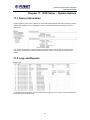
11.1
Device Information .............................................................................. 78
11.2
Logs and Reports ................................................................................ 78
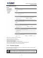
11.3
Maintenance......................................................................................... 79
11.3.1 Firmware Upgrade .............................................................................. 79
11.3.2 Through the Web Interface ................................................................ 80
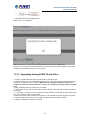
11.3.3 Upgrading through USB Thumb Drive ............................................. 81
11.3.4 Resetting the NVR to Factory Default.............................................. 82
11.4
Disk Status............................................................................................ 82
11.5
USB Backup......................................................................................... 83
11.5.1 Things to Pay Attention to the USB Backup Function ................... 84
11.5.2 Playing the Backup File with the NVR Media Player..................... 85
Chapter 12.NVR Local Interface............................................................................ 89
12.1
System Configuration ......................................................................... 89
12.1.1 Service .................................................................................................. 89
12.1.2 Display .................................................................................................. 89
12.1.3 Network................................................................................................. 90
12.1.4 User Account -- User setting.............................................................. 92
12.1.5 User Account -- User Group Setting................................................. 93
12.1.6 Disk........................................................................................................ 94
12.1.7 Channel Configurations -- Adding a Camera (Automatic Search)95
12.1.8 Channel Configurations -- Adding a Camera (Add manually) ...... 98
12.1.9 E-Map.................................................................................................. 100
12.1.10 Recording ........................................................................................... 103
12.1.11 Event Setting...................................................................................... 106
12.1.12 System Log .........................................................................................113
12.1.13 Maintenance........................................................................................114
12.1.14 USB Backup........................................................................................116
Appendix A: Ping IP Address.................................................................................118
5
Network Video Recorder with HDMI
NVR-820 / NVR-1620 Appendix B: Planet DDNS Application.................................................................119
Appendix C: Configuring Port Forwarding Manually......................................... 120
6
Network Video Recorder with HDMI
NVR‐820 / NVR‐1620 Chapter 1.
Product Introduction
1.1 Package Contents
The package should contain the following items:
z
NVR unit x 1
z
User’s Manual CD x 1
z
Quick Installation Guide x 1
z
RJ-45 Cable x 1
z
Power Cord x 1
z
HDD Screw Packet x 1
z
Mouse x 1
1. If any of the above items are missing, please contact your dealer immediately.
2. Using the power supply that is not the one included in the NVR packet will cause
damage and void the warranty for this product.
1.2 Overview
SMB Surveillance Solution
This NVR is suitable for introducing high-definition IP surveillance solution, and for upgrading
your CCTV system to IP system without re-cabling. The NVR-1620 and NVR-820 is the 16 /
8-channel Linux embedded NVR with HDMI local display from PLANET, bringing stable and
efficient system operation under a wide range of recording/network management/system
settings. This latest NVR could be used as a control center to control and monitor up to 16 / 8
network cameras (ONVIF supported) connected to this NVR locally or remotely, and also
supports image storage for evidentiary recording and data backup up to 2 hard disks, perfectly
designed for intelligent IP surveillance system. Users can just turn on the cameras and the
NVR to easily protect their life and properties under the IP networks. The recorded video files
can be saved in the NVR without the need for an additional PC for files storage, thus bringing
users a secure surveillance system at a lower total cost. It is fully compatible with iOS, Android
and Internet Explorer on Windows operating system for multi-platform remote access.
High Resolution Local Display
The NVR-1620 provides an HDMI and VGA video output interface for dual local display, which
can be connected to HDMI monitor or TV for doing monitoring in the full HD (1920 x 1080)
resolution, and check NVR system status on VGA monitor at the same time, eliminating the
need for a separate PC to view video from the unit. It also can be operated with the USB
keyboard / mouse and bundled remote control* to configure and monitor all the systems easily.
Performing Real-time Remote Monitoring
Up to 16 IP cameras can be connected to the NVR-1620 via a connected IP network. With the
NVR-1620, it delivers high performance to ensure stable recordings and smooth playbacks of
multiple megapixel cameras. Users can view remote surveillance in real time and play back
recorded videos via the web browser or the bundled CMS software.
Easy Configuration and Management
The NVR-1620 features smart setup wizard program to help users easily complete the device
installation. It supports web-based management interface for the administrators to remotely
manage the device via web browser without any concern. Furthermore, the NVR-1620 can
7
Network Video Recorder with HDMI
NVR‐820 / NVR‐1620 automatically search and find the available cameras in the network so it greatly reduces user’s
effort when setting up the system. This state-of-the-art and powerful software / hardware in
one design is considerable to fit in various network environments.
1.3 Features
¾
Hardware
Linux-embedded, highly reliable standalone NVR
Supports Gigabit Ethernet port
Supports VGA / HDMI dual local display
Supports 3.5" SATA x 2 HDD
¾
Video / Audio
Supports M-JPEG / MPEG-4 / H.264 compressions
Auto configuration for PLANET IP camera
Video resolution up to 5 mega-pixel (2560 x 1920)
Supports up to 120fps @ 1080P (H.264)
2-way audio support with enhanced audio quality
¾
Video Recording / Backup
Simultaneous recording and live video streams
Manual or schedule recording of 16 IP cameras
Video recycle function makes the video recording in 24/7
Exports record video file to AVI format to USB device or local storage
Instant Event Notification and recording
¾
Network Service
Easy access with PLANET Dynamic DNS and Built-in NTP Server
Supports DHCP Server/client (Auto detection)
Convenient Data Access (SMB/CIFS /HTTP /FTP)
¾
Easy Installation & Management
ONVIF compliant for interoperability
Supports Multiple Languages
Auto discovered by management software
E-Map interface in web and utility configuration
Web-based and management utility for easy configuration
Up to 16 NVR, max. 256 channels with the central management software
Supports USB keyboard, mouse, and joystick, IR remote control and Joystick(PTZ)*
Supports mobile phone remote view with WinCE 6.1, Android, Symbian S60,
iPhone, and Blackberry 4.6
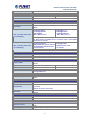
1.4 Product Specifications
Product
NVR-820
NVR-1620
Hardware
Ethernet
1 x RJ-45, 10/100/1000Base-T
USB Interface
1 x USB 2.0 for backup device and firmware upgrade
Video Interface
VGA / HDMI video interface
Audio Interface
Mic-in, line-in and line-out
Storage Device
2 x 3.5” SATA II hard disk connectors
LED
Power, Alarm, Status, HDD
Button
Power, Reset, Buzzer stop
8
Network Video Recorder with HDMI
NVR‐820 / NVR‐1620 IR Receiver
Built-in IR receiver
Camera
Max. Channels
8-channel IP Cameras
Add camera
16-channel IP Cameras
Manual / Smart Camera Search / Auto setup
Video
Compression
H.264 / MPEG-4 / M-JPEG
Resolution
5MP / 3MP / 1080P / 2MP / SXGA / 720P / FD1 / VGA / CIF /
QCIF
Max. live video frame rate
(Local Display)
Max. recording frame rate
(Local Display)
240fps@720P30
120fps@1080P30
80fps@3MP
Max. 5MP/channel
480fps@D1 30
360fps@720P30
120fps@1080P30
Max. 5MP/channel
*1: Supports Full HD1080P60
*2: NVR-1620 local display limit to 2 channel 1600 x 1200 (2MP)
resolution IP camera
240fps@1080P30,
4Mbps/channel, total 8-channel
120fps@3MP, 6Mbps/channel,
total 8-channel
480fps@1080P,
3Mbps/channel, total
16-chaneel
* Real performance may vary in different environments.
Audio
Audio Type
Two-way
Audio format
G.711, G.726 (Camera dependent)
Live Viewing
Display Mode
Live View / Playback / Full / Screen / Sequence view / Saved
views
Split Screen
1/4/9
1 / 4 / 9 / 16
Full Screen
1/4/9
1 / 4 / 9 / 16
Sequence Mode
Sequence All / Manually Selected cameras in 1/4 split view with
configurable timer
Snapshot
Video snapshot in JPEG format
PTZ Support
Digital PTZ / Auto Pan / Preset Point / Preset point Sequence
view
Playback
Split Screen
1/4
Play Method
Play / Pause / Stop / Forward / Reverse / Speed Adjust / Frame
by Frame
Search by time or event only
Bookmark
Intuitive timeline interface with bookmark function for easy file
export
Monitor
Dual Monitor
Main UI + Full screen live view / sequence view
Monitor Resolutions
1920x1080, 1280x1024, 1280x720, 1024x768
Network and Configuration
Network Service
TCP / UDP / HTTP / DHCP / DNS / ARP / ICMP / NTP / UPnP /
FTP
Streaming Protocols
Depending on the supported cameras
9
Network Video Recorder with HDMI
NVR‐820 / NVR‐1620 Triggers and Event
Event type
System Events –
z
System Start / Shutdown
z
System Settings modified
z
Camera Settings Modified
z
Start Recycle
z
Disk Full
Camera Events –
z
Motion/Sensor Detection
Event Action
z
z
z
z
z
z
z
Display red window on video of event channel
Buzzer alarm
Disable / enable event action
Duration of event action
Recording
Mail / FTP notification
E-Map notification
Management
Number of Groups
7 (Administrator / Guest / User Define * 5)
Privileges
Live View / Playback / System Configurations / Camera
Configurations / Recording Configuration / Event Configuration /
Maintenance
z
User Interface
z
z
Graphic local user interface (Operated by mouse, keyboard,
IR remote controller or USB joystick )*
Web Browser (Internet explorer 7 or above)
CMS Utility
Log Type
Alert / Event / User Access
Software Utility
Search utility / media player for recording export
Environment
Power
100~240V AC, 1.4A / Max. 50/60Hz
Consumption
90W
Operating Temperature
5~40 degrees C
Storage Temperature
-40~70 degrees C
Humidity
10~90% (non-condensing)
Weight
4.6 kg
Dimensions (W x D x H)
220 x 215 x 81 mm
10
Network Video Recorder with HDMI
NVR‐820 / NVR‐1620 Chapter 2.
Hardware Interface
2.1 Physical Descriptions
Front Panel
NVR-1620
NVR-820
LEDs
HDD x 2
Status
Green
Red
Amber
Network
Green
Amber
Green
Status
Red
Amber
Green
Power
Red
Amber
Red
Alarm
None
Buttons
Status
Definitions
Solid green when the HDD is mounted
Solid red for disk fail
Solid amber when recording is in process
Blinking when recycling
Solid green for activity on a 10 / 100Mbps network
Solid amber for activity on a 1Gbps network
Solid green for normal operation
Blinking green when firmware upgrade is done
Blinking red for failed firmware upgrade through USB disk
Blinking amber during firmware upgrade
Solid green - Normal operation
Blinking in green after pressing and holding the reset button for 5
seconds indicating the device will enter the restore default
process. Other LEDs remain unchanged during this state.
System off (power cord remains plugged in)
Fast blinking - During system initializing/starting.
Continuous blinking - When system is unable to start properly (All
other LEDs should be off when this LED is blinking in amber)
Slow blinking - The system is shutting down. Other LEDs go off
according to the stages of the process.
Blinking in red when a system/camera event occurs.
Blinking should last 10 seconds for each event
Goes off if reaches the 10-second duration, or when
buzzer stop button is pressed (if buzzer is triggered)
Definitions
11
Power
Reset
Buzzer
Stop
Buzzer
Beep
ON
OFF
Restore
default
Restart
Network Video Recorder with HDMI
NVR‐820 / NVR‐1620 Press and hold for 2 seconds
Press and hold for 2 seconds
Press and hold for 5 seconds
Press and hold for 2 seconds
STOP
Press and release to stop buzzer right away
Status
Complete
start
Initiating
restart
Initiating
shutdown
Definitions
Beep once (indicating the system is fully started)
Beep once (Indicating the restart process has begun)
Beep once (Indicating users to release the Power button
as the shutdown process has begun)
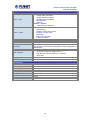
Real Panel
Connector
Description
Ethernet
10 / 100 / 1000Mbps network.
USB
Connect your USB flash disk for firmware upgrade and backup.
Video
VGA / HDMI
Audio
Line in / Line out / Mic
Power Supply
100~240V AC, 1.4A / Max. 50 / 60Hz
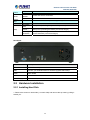
2.2 Hardware Installation
2.2.1 Installing Hard Disk
1. Remove the screws on both sides (1 on each side) and remove the top case by pulling it
toward you.
12
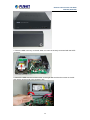
Network Video Recorder with HDMI
NVR‐820 / NVR‐1620 2. Place the HDD in the tray on the left. Slide it in until it is securely connected with the SATA
connector.
3. Secure the HDD with the tool-less screw on the right side and the other screw on the left
side, which can be found in the accessory box.
13
Network Video Recorder with HDMI
NVR‐820 / NVR‐1620 4. Place the top case and secure it with the screws on both sides.
14
Network Video Recorder with HDMI
NVR‐820 / NVR‐1620 Chapter 3.
Connecting to the NVR There are various ways you can connect to the NVR and below are the suggested methods for
different network setups:
The NVR is placed in a network with a DHCP server: Connect to the NVR by using “Device
Search” Utility.
The NVR is placed in a network without DHCP server (or you are connecting to it directly):
Access NVR with its default IP (192.168.0.20).
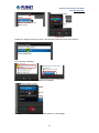
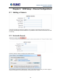
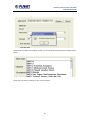
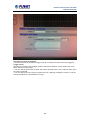
3.1 Using Device Search Utility
If the NVR is placed in a corporate network or a local area network where a DHCP server is
already presented, please install the “Device Search” utility from the bundled CD disk.
To begin, launch the “Device Search” utility from the CD and proceed with the installation.
15
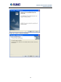
Network Video Recorder with HDMI
NVR‐820 / NVR‐1620 Please click “Next” to continue.
Please click “Install” to start the installation.
16
Network Video Recorder with HDMI
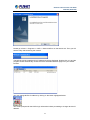
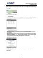
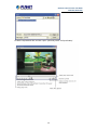
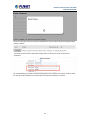
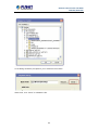
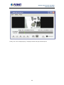
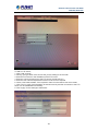
NVR‐820 / NVR‐1620 Once the installation is complete, please check the “Finish”.
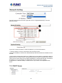
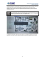
Please go to Start => Programs => NVR => Search NVR to run the search tool. Then you will
see the utility start searching the network.
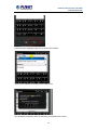
The NVR should be located and its IP address should be displayed: Double-click on it and the
program should automatically access the NVR’s web administration page from your default
browser.
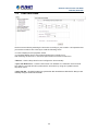
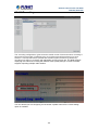
You may change NVR’s IP address by clicking on the button highlighted below.
You will be prompted for the NVR’s login information before proceeding to change device’s IP
address.
17
Network Video Recorder with HDMI
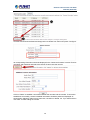
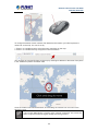
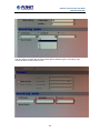
NVR‐820 / NVR‐1620 You may click on the button highlighted below to perform search again. Or double-click on any
of the search results to access NVR’s web administration page.
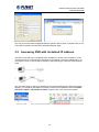
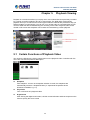
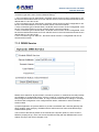
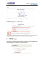
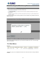
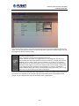
3.2 Accessing NVR with its default IP address
The NVR comes with a pre-configured static IP address “192.168.0.20”. However, it is only
used when there is no DHCP server presented in the network. Connect the NVR and PC to
your switch or hub, or connect the PC directly to the NVR using a crossover CAT5 Ethernet
cable.
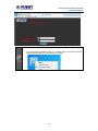
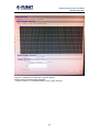
You can select utility or type the IP address to connect with NVR directly. After login window
appears, you should be prompted for the NVR’s username and password. Enter its default
username “admin” and password “admin” and then click ”OK” to enter the system.
18
Network Video Recorder with HDMI
NVR‐820 / NVR‐1620 •
Please make sure you are using Internet Explorer 7 or above.
•
If you are running Windows Vista or 7, please make sure you are running
Internet Explorer with the “administrator” privilege.
19
Network Video Recorder with HDMI
NVR‐820 / NVR‐1620 Chapter 4.
Web-based Management
This chapter provides setup details of the Internet Camera’s Web-based Interface.
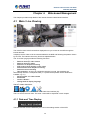
4.1 Main / Live Viewing
The main/live view is the first interface displayed once you access to the NVR through the
internet browser.
It displays the live video of all the cameras added to the NVR and following the pattern chosen
by the user. The interface has many functions explained below.
The “Live View” page provides the following functions:
•
Retrieve camera’s video stream
•
Retrieve camera’s status
•
Perform Live Sequence Viewing
•
PTZ Control (Click directly on the video)
•
Perform PTZ Preset Sequence viewing
•
Perform manual recording
•
Take snapshot - as soon as a snapshot selection is made, the snapshots are
automatically saved to x:\SnapshotFolder ("x" represents the partition where Windows is
installed, e.g: C:\)
•
Receive audio of a video stream
•
Send audio
•
Control “Buzzer”
•
Change web UI display language
The UI’s 5 main functions:
The bar displays the 5 main functions of the Web User Interface (UI).
The Live view is the main view .The other 4 views will be explained in each chapter.
4.1.1 Date and Time Display
The Date and the Time are defined by the user in the settings section of the NVR.
20
Network Video Recorder with HDMI
NVR‐820 / NVR‐1620 4.1.2 User’s Configuration
It displays the name of the current user.
If you click on the name of the user, the context menu offers the functions below:
- Language settings
- User setting
- Locking the screen
- Logout function
4.1.3 Hardware Event Notification
In this section, you will receive notifications if a warning sound is triggered or if the hard drive
of the NVR fails in recording data.
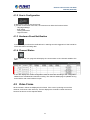
4.1.4 Channel Status
If you click on the icon, page tab will display the current status of the channels added to the
NVR.
It can also display the current configuration used for the event recording or the configuration
settled for the scheduled and manual recording. The channels status page is updated as long
as the NVR’s main user interface is open.
4.2 Video Frame
All the camera’s videos are displayed in this frame. If the cursor is pointing at one of the
cameras, it will show a bar at the top. The bar displays the channel’s number and some
functions as shown on the snapshot below.
21
Network Video Recorder with HDMI
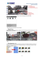
NVR‐820 / NVR‐1620 If you click on the name of the user, the menu will display as shown below:
The camera menu offers the functions below:
- Digital Zoom
After clicking the digital zoom button, hold the mouse left button and draw a square on the video
to specify the zoom in area
Once the image is digitally zoomed in, use the mouse scroll button to further zoom on or zoom
out the image. Hold and left-click on the image and move the mouse to move the zoomed in
video.
- Take Snapshot 1 / 3
User can select 1 or 3 continuous snapshots. As soon as a snapshot selection is made, the
snapshots are automatically saved to x:\SnapshotFolder ("x" represents the partition where
Windows is installed, e.g: C:\)
22
Network Video Recorder with HDMI
NVR‐820 / NVR‐1620 If the "3 continuous snapshots" option is chosen, the new window will display snapshots and let
you view them individually by using the "Prev", "Next" buttons as shown above.
- Audio in
Turn on/off audio of a live video.
- Lens Control
If this camera could control focus and Iris, the button of the selection could be active, otherwise
it will be highlighted. There are three selections of focus and iris as shown below.
- Preset Point Controls
This page focuses on just PTZ camera, and here are some definitions below:
- Add current position: Click this button and currently position will be added in the preset
point selection.
- Go to preset point: Select the preset point and the PTZ camera will move to this position.
the preset page will display, user can adjust the preset
- Preset points sequence: Click
point on this page; the other settings will be explained in each chapter.
- Auto pan controls: User can use “right”, “stop”, ”left”, “360 degree” button to control the
PTZ auto pan function.
- Changing Channel
User can select to change the view to other channels or disconnect the current channel
camera view.
23
Network Video Recorder with HDMI
NVR‐820 / NVR‐1620 - Enhancing Contrast
You are able to adjust brightness and contrast of the live video from the camera menu. The
default values of two parameters are 50%. User can adjust those values for 0% - 100%. The
layout of this bar is 10%.
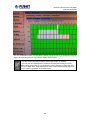
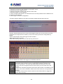
4.3 List Viewing
It displays the list of channels added to the NVR. Each channel represents a camera with its
name, the channel number and its currents status.
24
Network Video Recorder with HDMI
NVR‐820 / NVR‐1620 The channel status is defined by 3 colors:
- Red: The channel is recording and the live view is available
- Blue: The channel is connected and the live view is available
- Grey: The camera is disconnected
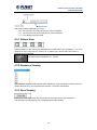
4.3.1 Pattern View
Different patterns of live view can be displayed on the video frame. You can display 1, 4, 9, or 16
cameras at once. Every time you click on an “n” pattern icon, the live video of the next “n”
cameras will be displayed.
The channel spilt of NVR-820 is 1, 4, and 8.
4.3.2 Sequence Viewing
The sequence mode will automatically switch between a single and group of cameras every a
certain period of time. You can define this period to 1 second to 60 seconds
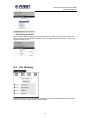
4.3.3 Save Viewing
Click on the save view button and you will able to name the current view and save it.
This will help to quickly display your configured views when needed.
25
Network Video Recorder with HDMI
NVR‐820 / NVR‐1620 4.4 Saved Viewing
This section can display the views that you have already saved.
You can choose the views from the list you have created. You are also able to switch between
saved views every certain period of time by clicking on the “start sequence function”.
If you check the box beside the name of the view, you can edit or delete the view.
4.5 Setting Up Password
The default login username and password are admin and admin. To change the password of
the admin account, go to “Setup” --> “System Configurations” --> “User Account”, click on the
“admin” account in the account list and then press the “edit” button to change its password.
Finally, click “Apply” to save the change.
26
Network Video Recorder with HDMI
NVR‐820 / NVR‐1620 4.6 Camera Installation
4.6.1 Adding a Camera -- Automatic Search
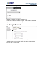
In “Settings” >> “Channel Configuration”, click the “Search” button to perform the camera
search.
You should be prompted to install Active Control component in order for the search to function
properly. Go ahead and click “Install”
After that, the search should begin and its status should be displayed:
27
Network Video Recorder with HDMI
NVR‐820 / NVR‐1620 Cameras found should be listed and simply select a camera from the list and press “Configure”
Its corresponding information should be displayed in the “Camera Information” section. Enter its
username and password and select the channel ID and name the camera.
Click on “Detect” to establish connection between the recorder and the camera. If connection
establishes successfully, camera’s detailed information should be polled and displayed as
shown below. Adjust its video format, frame rate, resolution or bitrate, etc. if you wish and then
click “Add” to finish adding the camera
28
Network Video Recorder with HDMI
NVR‐820 / NVR‐1620 4.6.2 Adding a Camera Manually
Simply follow the instruction described above but instead of using the “Search” function, enter
the camera’s IP address and credential in the “Camera Information” manually.
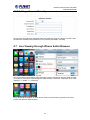
4.7 Live Viewing through iPhone Safari Browser
You can use iPhone and perform single channel live view to the NVR by using its Safari browser.
To be able to view the live video through the Safari browser, make sure “JavaScript” is on under
“Settings” >> “Safari” >> “JavaScript”
Once JavaScript is enabled, click the “Home” button on the iPhone to go back to the home
screen and open the Safari browser
29
Network Video Recorder with HDMI
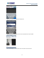
NVR‐820 / NVR‐1620 Type in the IP address of the NVR in the address bar
You should be prompted to enter the user name and password to access the NVR
Upon successful login, you should see the live view video of the first channel
30
Network Video Recorder with HDMI
NVR‐820 / NVR‐1620 Click on the “Channel” drop-down menu to select other cameras
If a PTZ camera is selected, the corresponding control buttons will display (control PT only)
This function is camera dependent and is not available to all cameras. Certain
cameras do not allow you to adjust image size and the selection “Auto” will be
used.
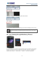
4.8 Live Viewing through Blackberry Phones
You can use Blackberry and perform single channel live view to the NVR by using its Safari
browser. To be able to view the live video through its browser, make sure “JavaScript” is
enabled under “Browser” >> “Menu button” >> “Options” >> “Browser Configuration”
31
Network Video Recorder with HDMI
NVR‐820 / NVR‐1620 Enable the “Support JavaScript” option, click the menu button and click “Save Options”
Go to “General Properties
Make sure two options illustrated above are enabled
Press the menu button and click the “Save Options” to save settings
32
Network Video Recorder with HDMI
NVR‐820 / NVR‐1620 Press the button highlighted above to go back to the browser
Type in the IP address of the NVR in the address bar
You should be prompted to enter its username and password for access
33
Network Video Recorder with HDMI
NVR‐820 / NVR‐1620 Chapter 5.
Playback Viewing
Playback is a function that allows you to play one or more videos that were previously recorded
by a chosen recording method or due to an event trigger. The NVR offers synchronized
playback from up to 4 channels and various types of search methods are provided to help you
find the footage you need quickly. You can turn on or off the audio of a recorded video at your
choice if audio was also recorded during the recording of the video. Playback video can be
viewed in full screen and snapshots can be taken and saved during a video playback.
5.1 Certain Functions of Playback Video
You can do the following by clicking camera menu on the playback video. It’s similar with live
view. User can refer the previous description.
z
Snapshot
Take snapshot - as soon as a snapshot selection is made, the snapshots are
automatically saved to x:\SnapshotFolder ("x" represents the partition where
Windows is installed, e.g: C:\)
z
Play Audio
Turn on/off audio of a playback video.
z
Digital zoom
After clicking the digital zoom button, hold the mouse left button and draw a square on the
video to specify the zoom in area
34
Network Video Recorder with HDMI
NVR‐820 / NVR‐1620 Once the image is digitally zoomed in, use the mouse scroll button to further zoom on or
zoom out the image. Hold and left-click on the image and move the mouse to move the
zoomed in video.
z
Take Snapshot 1 / 3
User can select 1 or 3 continuous snapshots. As soon as a snapshot selection is made,
the snapshots are automatically saved to x:\SnapshotFolder ("x" represents the partition
where Windows is installed, e.g: C:\)
If the "3 continuous snapshots" option is chosen, the new window will display snapshots
and let you view them individually by using the "Prev", "Next" buttons as shown above.
z
Adjust Brightness / Contrast
You are able to adjust brightness and contrast of the live video from the camera menu.
The default values of two parameters are 50%. User can adjust those values for 0% 100%. The layout of this bar is 10%.
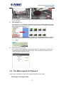
5.2 The Main Layout for Playback
Here is some explanation of other parts of playback page as shown below:
- Zooming on a range of time
35
Network Video Recorder with HDMI
NVR‐820 / NVR‐1620 If you click on the icon you can zoom on range of the time and get more details on the playback
bar. The “Display current playback time” button will display while the NVR plays the recording.
It can help user to find current playback time easily.
- Minimizing the Bar of the Playback
If you click on the icon, you can minimize the playback range to get more space for the videos.
- Exporting Playback Videos to AVI Files
User can export the recorded playback videos stored on NVR to a local computer and save
them in AVI file format. The files can then be played on the PC by a 3rd party media player such
as VLC player or Windows Media player.
Once you locate the recorded videos with steps described in the previous section, move the
time bar to the specific start time which you want to export and then click “Bookmark” button.
This specific time will be marked by a blue line. Move the time bar to the end time and click the
“Bookmark” button again. You can find that this button will be changed to “Clear” button.
Click the “Download” button and a new dialog will pop up and allows you to specify the time
frame (or length) of the video you wish to export.
36
Network Video Recorder with HDMI
NVR‐820 / NVR‐1620 Click the
button to pull down the calendar to help you specify the month, date and the year
Specify the starting and ending hours of the video by entering numbers in the text boxes.
Hit the “Start” button to start exporting. The file will be automatically named and saved under the
C:\ partition.
You will be notified once the process is completed successfully
37
Network Video Recorder with HDMI
NVR‐820 / NVR‐1620 The exported AVI file will be saved under the C partition (or the partition where Windows is
installed)
ffdshow is required in order to play the exported AVI file with Windows Media
Player. You can get it at “http://sourceforge.net/projects/ffdshow/”
5.3 Playing Exported Playback Videos with NVR
Media Player
You can also use the NVR Media Player to play the exported AVI files. This can save you the
trouble of installing third-party media player or codecs when playing the exported AVI videos.
The NVR Media Player will be automatically installed after the CMS software is installed. You
can find it in the Windows Start menu. You also can click this
software on the playback page.
Click “Open” >> “AVI File”
38
icon to download this
Network Video Recorder with HDMI
NVR‐820 / NVR‐1620 Locate the exported AVI file, and click “open”. (Normally under “C:\ExportFolder)”
39
Network Video Recorder with HDMI
NVR‐820 / NVR‐1620 Chapter 6.
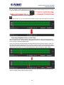
Event Viewing
This section displays the last events recorded by the NVR.
The events can only be detected and displayed if you have configured it on the NVR’s settings.
You can display the event of all the channels at once or by each channel.
You can click on one of the pictures on the bottom of the UI to display the event related to it. The
event can also be displayed if you choose them from the list on the right side of the UI.
The video will then start playing
40
Network Video Recorder with HDMI
NVR‐820 / NVR‐1620 6.1 Opening Event Snapshot Images with NVR Media
Player
The NVR sends snapshots that are taken when an event occurs to a destined FTP server or
mail recipient. These types of snapshot images are saved in a proprietary image file format, h4i
or p4i, and can only be opened by the NVR media player.
To do so, Select “Open” from the top menu and then select “Image File”. A new dialog should be
displayed which lets you locate the image file.
41
Network Video Recorder with HDMI
NVR‐820 / NVR‐1620 Chapter 7.
NVR Setup – System Configurations
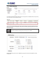
7.1 Network Setup
The “System Configurations” page provides users with options to set up the device quickly and
properly. After properly configuring all settings in all the sub-pages, users should expect a fully
working network video recorder that is ready to manage cameras on the network. We will start
by configuring its network settings to make sure it works correctly in your network. Next, we will
help you adjust the system time so videos will be recorder with correct timestamp. To better
secure the system for unwanted disturbance, we will guide you on setting up user’s account
and privileges to prevent settings from getting altered by users other than the system
administrator. Lastly, we will tell you what you should expect after installing a hard disk and how
to prepare the hard disk for the video recording.
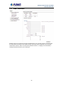
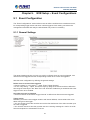
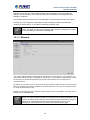
7.1.1 Network Settings
You need to adjust settings on this page for the device to work properly in your network. It is
critical that settings here are configured correctly based on your network configurations so that
the recorder can be administered through the local area network and cameras can be
connected from it.
By default, the recorder is set to "Auto Mode" which if there's a DHCP server in the same local
network, the NVR can obtain IP address from DHCP server, and you can locate the NVR by
using the NVR search utility.
If there's no DHCP server in the network, and the NVR is set to "Auto Mode", it will use its own
default static IP 192.168.101.50.
42
Network Video Recorder with HDMI
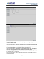
NVR‐820 / NVR‐1620 The NVR supports three connection types that can be configured depending on how the
network is set up.
If you wish to set the recorder to a static IP address in your local area network,
1. Choose “Static IP” from the “Connection Type” drop-down menu
2. Enter the IP address, subnet mask, default gateway address and DNS server address for the
recorder
* The recorder can detect the presence of a DHCP server upon startup. It sets itself to static IP
address if there is no DHCP server currently presented in the network. Its DHCP server function
is also turned on at the same time to assign IP addresses to cameras that are later connected to
the network or you can manually turn off the DHCP server function from "System
Configurations">>"Network Setup">>"DHCP Server" if you wish to use a separate DHCP
server.
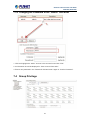
7.1.2 DHCP Server
43
Network Video Recorder with HDMI
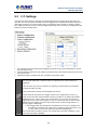
NVR‐820 / NVR‐1620 The built-in DHCP Server function is NOT always configurable and is greatly dependant to the
connection type that is set to "Device Network Setting":
1. If the connection type is "Auto Mode", the DHCP server function is NOT configurable. It will
be ON if the NVR doesn't obtain an IP from a DHCP server in the local network and uses its own
default static IP 192.168.101.50
2. If the connection type is "Auto Mode", the DHCP server function is NOT configurable. It will
be OFF if the NVR obtains an IP from a DHCP server in the local network.
3. If the connection type is "DHCP Client", the DHCP server function is NOT configurable. It will
be OFF if the NVR obtains an IP from a DHCP server in the local network.
4. If the connection type is "DHCP Client", the DHCP server function is NOT configurable. It will
be ON if the NVR doesn't obtain an IP from a DHCP server in the local network and uses its own
default static IP 192.168.101.50
5. If the connection type is "Static IP", the DHCP server function is configurable and can be
turned on/off manually.
7.1.3 DDNS Service
DDNS, which stands for “Dynamic DNS”, is a method, protocol, or network service that provides
the capability for a networked device, such as a router or computer system (in this case, the
NVR) using the Internet Protocol Suite, to notify a domain name server to change, in real time,
the active DNS configuration of its configured host names, addresses or other information
stored in DNS.
A popular application of dynamic DNS is to provide a residential user’s Internet gateway that
has a variable, often changing, IP address with a well-known host name resolvable through
standard DNS queries.
This is useful if the NVR is placed on the Internet with a dynamic public IP, which once the
DDNS is properly set up, users can access the NVR remotely with the DDNS domain name
without worrying if the IP has changed or not.
44
Network Video Recorder with HDMI
NVR‐820 / NVR‐1620 *Please make sure a valid DNS server has been configured under the “Network
Setting” page in order for this function to work properly.
*The NVR currently only works with free DDNS service provided by “DynDNS”.
For more information, please go to www.dyndns.com
*If the NVR is placed behind a router or Internet gateway, please make sure port
forwarding for port 80 is configured on the router or the gateway in order for the
DDNS function to properly register with the service. It’s often suggested to use
the DDNS function in the router/ gateway for such case instead.
*Once you have the DDNS function successfully up and running, please DO NOT
forget to configure port forwarding for the NVR web port (default 80) and the
streaming port (default 9877) in the router/gateway for remote viewing. You can
then type in http://yourddnsdomain in the browser to access the NVR remotely for
live viewing.
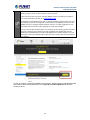
In order to properly configure the DDNS service function, please register a free DDNS domain
name and account from DynDNS first. Go to http://dyn.com/dns/dyndns-free/ from the
browser to do so.
45
Network Video Recorder with HDMI
NVR‐820 / NVR‐1620 Fill in the necessary fields as illustrated above
The page will check whether or not another user has used the host name you entered as soon
as you click the “Add to Cart” button. If you see the message below, simply enter a different one
and click “Add to Cart” again.
46
Network Video Recorder with HDMI
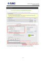
NVR‐820 / NVR‐1620 Once you get to the next page, fill in the necessary fields as illustrated above
47
Network Video Recorder with HDMI
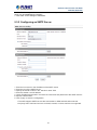
NVR‐820 / NVR‐1620 Go back to the NVR’s DDNS service configuration page under “Setup” >> “System
Configuration” >> “DDNS Service”. Fill in the domain name you picked during the registration in
the “Domain Name” field and the username/password you created in the “User ID” and
“Password” field and click “Apply” to finish
You can click the “Check DDNS Status” button to check the DynDNS service status. If you are
getting a “Disconnected” message, it means that DDNS service server is down or the NVR is
not connected to the Internet. If everything is ok normally, you should be prompted with a
success message
48
Network Video Recorder with HDMI
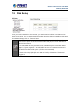
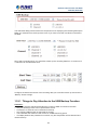
NVR‐820 / NVR‐1620 7.2 Time and Date
Set the time and date by selecting the time zone according to your location. It is imperative that
you set the recorder’s time correctly to avoid the following errors:
• Incorrect display time for playback videos
• Inconsistent display time of event logs and when they actually occur
After selecting the time zone, choose an option below to set the recorder time.
• Manual – Use the drop-down list and configure the time manually.
• Sync with NTP server – enter the host name or IP address of a valid NTP server and set
how often the recorder should synchronize the time with it by using the “Update interval”
drop-down menu.
• Sync with PC – Check this option to synchronize the recorder time with the PC that you are
currently using to access the recorder.
49
Network Video Recorder with HDMI
NVR‐820 / NVR‐1620 7.3 User Account
Multiple users can access the recorder simultaneously. You can add, remove, and edit users
by using options provided on this page to keep user information organized. Each recorder
comes with a built-in “admin” account with password “admin”. It’s highly recommended to
change the password upon your initial login.
50
Network Video Recorder with HDMI
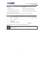
NVR‐820 / NVR‐1620 7.3.1 Adding a New User
• Enter a user name and password in “User Account Information”. All other fields are optional
for your own reference.
• Select a group from the “Group” drop-down menu to assign the new user to a particular
group • Enter a short description for the account if you wish.
• Click “Add” to finish configuration.
51
Network Video Recorder with HDMI
NVR‐820 / NVR‐1620 7.3.2 Changing the Password of the “Admin” Account
1. Click and highlight the “admin” account in the account list and click “Edit”.
2. Its information should be displayed in “User Account Information”.
3. Enter a new password in the “Password” field and enter it again in “Confirm Password”.
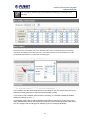
7.4 Group Privilege
52
Network Video Recorder with HDMI
NVR‐820 / NVR‐1620 Group Privilege is where you can create multiple customized access policies for situations if
you need the recorder to be accessed by users other than the administrator. You can do so by
creating a group, and then remove access privileges for certain configuration pages or
cameras. Users that are created and assigned to this group will have limited access instead of
full administration rights.
The recorder comes with seven built-in groups and five built-in privilege profiles, except the
“admin” and the “guest” accounts; the other five groups are fully customizable or you can
simply assign a group with one of the default privilege profiles. You can, however, assign more
than one users to the “admin” account if you wish to do so. The guest account comes with a
“view-only” privilege on the “Live View” page, and users in this group do not have the power to
make any changes on the “Live View” page or have access to pages other than the “Live View”
page.
To create a group, select a group from the “Group” drop-down
You can change the group name by clicking the “Change Group Name” button. A text box will
be displayed for you to enter the new group.
Choose what type of privilege you would like this group to have from the “Privilege Type”
drop-down menu.
Its access privilege will then be displayed. You can alter its settings by allowing or denying
access to other cameras using the checkboxes instead of accepting the defaults
53
Network Video Recorder with HDMI
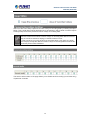
NVR‐820 / NVR‐1620 7.5 Disk Setup
Once you install a hard disk to the recorder, you would need to initialize it so that it can be
ready for recording. You can obtain basic information about the disk you installed on this page.
To initialize it, simply click the “Format” button.
*Due to the chipset limitation, “Hotswap” is NOT supported for SATA HDD. Please
make sure to power on the SATA external HDD and plug it in to the NVR before
the NVR is turned on.
*The USB HDDs will only be listed on the "USB Backup" and "Hard Disk Status
pages in "System Options". The USB HDDs have to be formatted in advance in
FAT16/FAT32 or EXT3 file system. (FAT32 is recommended)
* Please plug in the USB HDD only after the NVR is fully started. The internal
HDDs will NOT be properly detected if the NVR is powered on with USB HDD
plugged in.
54
Network Video Recorder with HDMI
NVR‐820 / NVR‐1620 Chapter 8.
NVR Setup -- Channel Configurations
8.1 Adding a Camera
The NVR provides two options for adding a new camera. Users have the option to let the
recorder automatically find the cameras or it is possible to enter camera’s information and add
it manually.
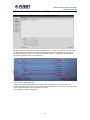
8.1.1 Automatic Search
Click the “Search” button to perform the camera search.
You should be prompted to install Active Control component the first time you visit the page in
order for the search to function properly. Go ahead and click “Install”.
55
Network Video Recorder with HDMI
NVR‐820 / NVR‐1620 Once you have the ActiveX component installed, the search status should be displayed after
clicking "Search"
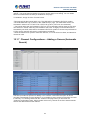
Cameras found should be listed and simply select a camera from the list and press
“Configure”
Its corresponding information should be displayed in the “Camera Information” section. Enter
its user name and password and select the channel ID and name the camera.
56
Network Video Recorder with HDMI
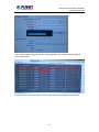
NVR‐820 / NVR‐1620 Click on “Detect” to establish connection between the recorder and the camera. If connection
establishes successfully, camera’s detailed information should be polled and displayed as
below.
Adjust its video format, frame rate, resolution or bitrate, etc. if you wish. You can also click on
the “Preview” to preview the live video of the camera.
Click “Add” to finish adding the camera
.
*If cameras are marked with "*" in the search result, it means those cameras are
already configured and connected to the NVR
57
Network Video Recorder with HDMI
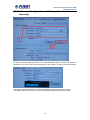
NVR‐820 / NVR‐1620 Once the camera's settings are polled and displayed, you can also enable "continuous"
recording and adjust its recording quality settings before adding the camera.
Some cameras are capable of multiple streaming profiles, in which different video codecs are
used for different purposes.
You will be able to use a different video format for continuous recording if it's a multi-stream
capable camera.
There are two types of fps settings here, one is the fps that NVR sets back to the camera, and
this is the fps NVR will be receiving from the camera. The other is recording fps, which will be
limited by the live fps. (e.g.. if the live fps is set to 10, choose "Full" in the recording fps
meaning it will only record at a maximum of 10fps.
For MPEG/H.264, only i frame or full (i+p frame) can be selected for recording fps.
58
Network Video Recorder with HDMI
NVR‐820 / NVR‐1620 For single stream camera, only the recording fps can be adjusted.
8.1.2 Adding a Camera Manually
Simply follow the instruction described above but instead of using the “Search” function, enter
the camera’s IP address and credential in the “Camera Information” manually.
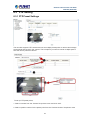
8.2 OSD Settings
The OSD (On Screen Display) allows users to add informational text message and embed it
onto the video. By default, this function is turned off. To add texts to one or more videos, select
a camera you would like to add text to and choose “Display OSD”
59
Network Video Recorder with HDMI
NVR‐820 / NVR‐1620 Choose one or more display options if you would also like the recorder to automatically embed
the system time or the frame rate for you. Or simply choose to display a custom message of
your own.
Next, define where the text will be displayed by either entering an X/Y value based on
percentage or use the system pre-defined position from the drop-down menu.
Click on the “Preview” button to see the preview of your setting and click “Apply” to save the
configuration.
The texts can be further adjusted with changes to a different size, color or font so they can be
more visible on the video.
60
Network Video Recorder with HDMI
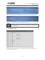
NVR‐820 / NVR‐1620 8.3 PTZ Setting
8.3.1 PTZ Preset Settings
The recorder supports PTZ cameras and can set multiple preset points or retrieve and manage
preset points that are set in the camera. This is helpful if you need to monitor multiple spots in
one area from a particular camera.
To set up PTZ preset points,
1. Select a camera from the “Camera” drop-down menu and click “Add”.
2. Select a position number for the preset point from the “Position Number” drop-down menu
61
Network Video Recorder with HDMI
NVR‐820 / NVR‐1620 and fill in a name in the “Position Name” field for easier identification.
3. Use the PTZ control provided on the configuration page to set the preset point
Ultimately, you can choose to make this preset point a “Home” point among all other preset
points, as well as making the camera to move to this particular point when an event is
triggered.
* “Move Here when Event Trigger”: In order for this function to work properly,
please also complete configuration in “Event Configuration” >> “Event Trigger”
8.3.2 PTZ Preset Sequence
Once you have multiple preset points defined for a camera, it is convenient for monitoring to
set up the sequencing viewing among those preset point and let the recorder automatically
switch between them for you.
62
Network Video Recorder with HDMI
NVR‐820 / NVR‐1620 To configure preset sequence for a camera,
1. Select a channel from the “Channel” drop-down menu. The available preset points should
be listed in the “Camera Presets” section.
2. Pick the ones you like for sequence viewing and press the “->” button to move them to the
“Preset Sequence” section, then
3. Use the Up and Down buttons to adjust their sequencing positions.
4. Finally, select a dwell time from the drop-down menu and click “Apply” to save the
configuration
8.4 E-Map Setting
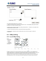
8.4.1 Local E-Map Setting
E-Map monitoring is a function that alerts users whenever there is an event triggered (e.g.
motion detected) from a camera with a geographical perspective. With this function, users can
quickly identify which camera has detected an unusual event and where this event is
happening. This function works by incorporating the event detection function as well as the
recording function, which, as a result, helps users take all the necessary actions when an
63
Network Video Recorder with HDMI
NVR‐820 / NVR‐1620 unusual event occurs.
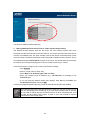
To replace the map, click the “Browse” button to locate the new map image file from the local
PC and then click “Upload”.
* Only JPG, PNG, and GIF file formats are supported with file size under 100KB.
Then click and drag the camera icon to move the camera to define its location.
Access the event monitoring page from the upper-right hand corner menu.
64
Network Video Recorder with HDMI
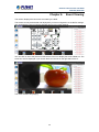
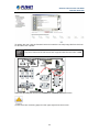
NVR‐820 / NVR‐1620 When the NVR receives an event triggered from any of the cameras, their videos will be
displayed on the E-Map and you can double-click on the video to enlarge it.
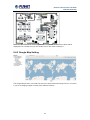
8.4.2 Google Map Setting
The Google Map monitor is a similar function to the aforementioned E-Map monitor. It is useful
if you are managing multiple cameras from different locations.
65
Network Video Recorder with HDMI
NVR‐820 / NVR‐1620 To configure locations of each camera, first determine the location you’d like to place the
camera to on the map. You can do so by:
1. Zoom in to a smaller area by using the zoom control bar on the map
2. Zoom in to a smaller area by using the mouse scroll button
You can also go to a specific place on the map by entering its address or the name of the place
in the “Address or places of interest” field
Once the location has been determined, click and drag the camera icon to move it to the
desired location
* The Google Map Monitor requires active Internet connection and cannot be
used in conjunction with the regular E-Map monitoring function.
66
Network Video Recorder with HDMI
NVR‐820 / NVR‐1620 Chapter 9.
NVR Setup -- Event Configurations
9.1 Event Configuration
The “Event Configurations” section allows users to define conditions that constitute an event,
its corresponding trigger action and when it will be triggered. Such setting can reduce the
management overhead and notify the administrator only when it’s necessary.
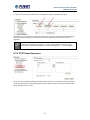
9.1.1 General Settings
The general settings section can help you quickly configure when an event is triggered, how
often events are triggered and the corresponding actions when events are triggered.
Start the event configuration by defining the general settings:
Define when an event will be triggered
• Choose “Always” or “Only during...” under “Event Trigger Duration”
• For the “Only during...” option, choose the days by using the check-box and then define the
time range in those days in the “Start Time” and “End Time” fields that you would like the event
trigger function to be enabled.
How often an event is triggered
• Set a time interval under “Event Trigger Interval” to define how often events are triggered
Trigger action
Now that you have the event trigger duration and interval defined, choose what action to be
taken during an event trigger:
• You can choose to have the recorder sent out the first few frames of the video recorder upon
an event is triggered.
• You can also choose to have the recorder sent out a warning message in e-mail or in txt file
format and upload it to a destined FTP server.
67
Network Video Recorder with HDMI
NVR‐820 / NVR‐1620 9.2 I / O Settings
This function allows users to manage camera’s digital input and output ports right from the
recorder. You can set up the recorder to receive triggers from a particular camera’s input port
and trigger a device, such as an alarm that is connected to the recorder or camera’s output
port. Cameras that do not have a built-in digital input/output port can also be configured to pair
with the recorder’s DI/DO ports.
1. For cameras that come with physical digital input ports, their ports will be listed in the far
left drop-down menu.
2. Pick the desired channel for I/O mapping, and then select the camera’s input port from the
drop-down menu.
3. Select the trigger condition from the “Condition” drop-down menu.
*The recorder does not control camera's input or output ports in a way to let you
pair recorder itself with a camera's input or output port for event receiving or
triggering.
*The recorder only acts as a medium for pairing up input/output ports between
cameras and the recorder.
*Only connected cameras will be displayed in the list.
*Some cameras only allow one trigger source to be configured at a time, e.g.,
If the camera has the motion detection function turned on, its digital input will be
disabled and vice versa. Under such circumstance, if you set to use camera’s
digital input port as the event trigger source, you will not be able to select motion
detection as the trigger source for this camera under “Event Configurations” >>
“Event Trigger” setup page.
• The image(s) that are uploaded to the destined FTP server or emailed to a
destined mail recipient are in their own proprietary image file format (.h4i
or .p4i), which can only be opened by the NVR media player.
.h4i if event was recorded in H.264, .p4i if event was recorded in MPEG4. .jpg if
event was recorded in MJPEG.
68
Network Video Recorder with HDMI
NVR‐820 / NVR‐1620 9.3 Event Servers
9.3.1 Configuring an FTP Server
Event servers are to be used with event trigger actions. In case of unusual motion detected by
the camera or a disk failure, the recorder can send notification with the acceptable format
(image/txt) to a destined event server according to the configuration.
To add an FTP server,
1. Start by giving a name to the server that you are adding to the recorder.
2. Enter the host name or the IP address of the FTP server.
3. Enter the communication port of the FTP server (usually port 21).
4. Enter the user name and password of the FTP server if it’s required.
5. Check “Use Passive Mode” if it’s required or leave it unchecked to use active mode.
69
Network Video Recorder with HDMI
NVR‐820 / NVR‐1620 6. Click “Test” to verify if all information is entered correctly and the connection to the FTP
server can be established successfully.
7. Click “Add” for the settings to take effect.
9.3.2 Configuring an SMTP Server
1. Enter the host name or the IP address of the SMTP server
2. Enter the port of the SMTP server
3. Specify the sender’s name in the “Sender’s name” field
4. Enter the sender’s e-mail address
5. Check “Enable Authentication” and enter the user name and password of the SMTP server if
it requires authentication.
6. Click “Apply” to save the configuration
• The NVR supports SMTP servers that use base64 or MD5 authentication methods.
• 3rd party free E-mail services such as Gmail, Hotmail, or Yahoo mail are not supported.
70
Network Video Recorder with HDMI
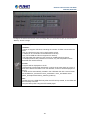
NVR‐820 / NVR‐1620 9.4 Event Triggers
We have finished defining how an event will be triggered and which servers will be receiving
notifications in the previous two sections, now we can finish up the event configuration by
setting:
•Which channels will have event trigger function enabled
•What is considered to be an event.
•Where the warnings will be sent to and how they will be sent
Use the checkbox to enable event trigger on the desired channels.
*Once motion detection is enabled on this page, please configure the motion area
and enable motion detection in the corresponding channels (cameras) from
camera's own web UI. The NVR only detects the first motion area set in the
camera. The NVR recognizes the first motion area by its ID number set in the
camera.
* Enabling the “custom event” option allows the NVR to receive events from the
CMS software and start recording; events such as the intelligent video detection
in the CMS.
71
Network Video Recorder with HDMI
NVR‐820 / NVR‐1620 Define which system events should trigger the recorder to send out notifications.
Define how the notifications will be sent and where they will be sent.
Event trigger may not work for cameras that are placed outside of your local
network or on the Internet until the “UPnP Port Forwarding” is enabled in both the
NVR and the router.
72
Network Video Recorder with HDMI
NVR‐820 / NVR‐1620 Chapter 10. NVR Setup -- Recording Configurations
10.1 General Settings
The “recording configurations” gives users the overall control of how and when a recording is
performed and the quality of different types of recordings performed on each channels. It can
help the recorder to operate with sufficient system resource by performing recording only when
it’s necessary with adjustable recording frame rate.
You can define the following in “General Settings”:
• Pre-Alarm/Post-Alarm recording length
• Recording frame rate
• Define to always keep a number of days of previously recorded data
• Enable/disable different recording types on different cameras
• Enable/disable audio recording
The “recording buffer” allows user to define “pre-alarm” and “post- alarm” time for event
recordings. The “pre-alarm” time sets the NVR to record in advance when an event is triggered.
The “post-alarm” time sets the NVR to continue recording for a period of time after an event
trigger is finished.
73
Network Video Recorder with HDMI
NVR‐820 / NVR‐1620 The “Pre-alarm” function only works when the “Continuous” recording is also
activated.
Recording frame rate allows you to set different frame rates for different types of recording
instead of recording at one frame rate only. Use the drop-down menu and select one of the
pre-defined frame rates for a particular recording type
You are able to use the same video format for recordings or you can choose other formats for
different recording purposes if it's a multi-stream capable camera.
If you chose to use a different video format for recording, you are able to adjust its detailed
settings by clicking on the "...".
A new dialog will pop out for further detailed configurations. Noticing the "Frame rate" in this
dialog represents the live fps that will be set back to the camera for this particular video format.
You can configure the recording fps for different types of recordings individually.
74
Network Video Recorder with HDMI
NVR‐820 / NVR‐1620 Users can also set to keep a previous number of days of recording data by enabling the option
below. This is quite often used in application such as banking in which certain countries require
to always keep a minimum previous number of days of recording data.
* If this option is enabled, once the hard drive is full, the recycle function will then
start but it will ensure that the number of days of recording data defined here will
stay in hard drive instead of wiping out 20GB of data at a time.
* If the hard drive is not full, the NVR re-calculates twice a day (each at 2:30am
and 2:30pm) to keep the defined number of days of recording data from these two
particular points of time backward.
The section at the bottom of the page allows you to disable audio recording (record video only)
of particular channels.
75
Network Video Recorder with HDMI
NVR‐820 / NVR‐1620 10.2 Schedule Recording
You can define the time range of the schedule recording for all channels on this page.
To configure a schedule recording
Use the “Channel” drop-down menu and select a camera first.
You can use the schedule table to set the time range. Click the cell boxes and then move
horizontally to let you set what hours to perform recording during a day. Click and move
vertically to let you set what days to perform recording at a specific time.
* Each cell box represents 15 minutes of time. Click one or more boxes to omit
consecutive recording.
76
Network Video Recorder with HDMI
NVR‐820 / NVR‐1620 You can also use the “Quick Configuration” to define recording time range instead of clicking
cell boxes one by one on the timetable. Simply check what days you would like to perform
recording and specify the recording duration by either choosing “All Day” or enter a start and
end time for specific recording duration.
Select the “Copy Schedule to Channel:” option if you would like to set the same recording
schedule to another camera.
Alternatively, you can click on “Copy Schedule to All Channels” and apply schedule setting to
all channels at once.
77
Network Video Recorder with HDMI
NVR‐820 / NVR‐1620 Chapter 11. NVR Setup -- System Options
11.1 Device Information
System Options gives users a glance of the overall system status and allows users to perform
maintenance tasks such as upgrading firmware, restore/backup device settings or reboot
device, etc.
The “Device Information” provides the general information of the device such as firmware
version and system time. It also provides information of the current network settings and
status.
11.2 Logs and Reports
“Logs and Reports” keeps a record of what’s been happening to the device and provides basic
information for troubleshooting.
78
Network Video Recorder with HDMI
NVR‐820 / NVR‐1620 11.3 Maintenance
“Maintenance” provides functions for users to:
• Reboot the NVR when necessary
• Reboot cameras directly from the NVR
• Perform Firmware Upgrade
• Back up the NVR’s settings to a local hard drive
• Restore the NVR’s settings from a previously saved configuration file
• Reset the NVR’s settings to their factory default values
11.3.1 Firmware Upgrade
The firmware can be upgraded through web UI or USB. Before upgrading firmware, please
back up configuration in advance.
** The firmware file comes with a “.tar.gz” file extension, please use the file
as it is, DO NOT unzip it. It’s normal that you may only see “.tar” as the file
extension in Windows as the OS hides the known file extension by default.
79
Network Video Recorder with HDMI
NVR‐820 / NVR‐1620 11.3.2 Through the Web Interface
Login into NVR’s web management UI, and go to "NVR Setup" >> "System
Options"->"Maintenance"
In the "Upgrade NVR's Firmware" section, click "Browse" and select new firmware file
A new dialog should display and let you choose the location of the firmware file.
80
Network Video Recorder with HDMI
NVR‐820 / NVR‐1620 When done, click “Upgrade”.
Follow the on screen instruction and wait for the process to finish (After upgrade, the system
will reboot automatically, it’s part of the process)
11.3.3 Upgrading through USB Thumb Drive
1. Prepare a USB flash disk and format with FAT or FAT32 format
2. Place the firmware in the USB flash disk and make sure it’s placed at the top-level directory.
Please do not place the file in a folder. (Make sure to change the firmware file name to
“firmware” and leave its file extension “.tar.gz” as it is before placing the file to the USB
disk)
3. Plug USB flash disk into USB port on the NVR.
4. The System LED on the NVR will start to flash in amber. This indicates firmware upgrade is
in process.
5. *** Warning *** Please wait until upgrade process finishes. Interrupting the upgrade process
may cause system not to work anymore.
6. Wait until System LED remains solid in amber. This indicates firmware upgrade is finished
7. Power off the NVR and remove the USB disk to power the unit back on again
8. Restore configuration file back if needed.
81
Network Video Recorder with HDMI
NVR‐820 / NVR‐1620 11.3.4 Resetting the NVR to Factory Default
To reset the recorder back to its factory default, click the “Restore Factory Default” button and
begin the process.
The process should be displayed and you should be prompted back to the “Live View” page
after it is completed.
11.4 Disk Status
“Disk Status” gives you more detailed information of the hard drive that is currently installed in
the NVR.
82
Network Video Recorder with HDMI
NVR‐820 / NVR‐1620 11.5 USB Backup
It’s a function that allows users to back up the recording data in its database file format (not AVI)
to the externally connected USB hard disk.
You can check the “Disk Status” page under “System Options” to see if the USB disk has been
detected by the NVR. If it's available, it will also be in the USB HDD drop-down menu on the
USB backup page.
* It needs a USB disk containing free space larger than 100MB.
Once it’s detected, go back to the “USB Backup” page and it should be available for further
configuration
83
Network Video Recorder with HDMI
NVR‐820 / NVR‐1620 The USB hard disk(s) will be listed in the drop-down menu displaying the remaining disk space.
Make your selection from the drop-down menu if you have more than one disks connected to
the NVR.
Next, select channels which you would like to back up the recording data from. A maximum of
4 channels can be selected at once.
Configure the start and end time of the recording data you would like to back up and click the
“Backup” button to begin.
11.5.1 Things to Pay Attention to the USB Backup Function
Limitation:
• It does not support USB Hub extending the number of HDD connected to the NVR.
• Only one backup process can be performed at a time.
• A maximum of channels can be selected for backup.
• Only FAT32 USB hard disk is supported for backup.
• The USB hard disk needs to have more than 100MB remaining space.
• If multiple partitions are presented in one disk, only the first partition will be detected and
used for backup
84
Network Video Recorder with HDMI
NVR‐820 / NVR‐1620 Process:
• Progress will be displayed on the UI.
• If the backup process gets interrupted, in which the process stops at a point of time that is
before the “END Time” user defined, such time will be displayed on the UI.
• A folder will be automatically created in the USB hard disk with a name format like
0028687831_20100610151515_2010060511 0010_20100606110010
(MAC_backupbuttonclicktime_starttime_ endtime).
Note:
• Please plug in the USB HDD only after the NVR is fully started, or the HDDs will be
incorrectly mounted.
11.5.2 Playing the Backup File with the NVR Media Player
The backup files can be played with the NVR media player. To do it, open the player and select
“Open” >> “Media Database”.
Click “Browse...” to select the file from the USB disk.
85
Network Video Recorder with HDMI
NVR‐820 / NVR‐1620 A new dialog should be prompted for you to select the file location.
When done, click “Check” to validate the file.
86
Network Video Recorder with HDMI
NVR‐820 / NVR‐1620 Once the file has been successfully verified, you should be prompted with the message shown
below.
Select the time zone according to your current location.
87
Network Video Recorder with HDMI
NVR‐820 / NVR‐1620 Finally, click “OK” to begin playing. The player should now play the backup file.
88
Network Video Recorder with HDMI
NVR‐820 / NVR‐1620 Chapter 12. NVR Local Interface
12.1 System Configuration
12.1.1 Service
You will the see the "Service" configuration page first when visiting the Configuration page.
You are able to set a unique device name, set system time and configure DDNS on this page.
12.1.2 Display
The "Display" configuration page allows you to choose the most optimized display resolution
for the monitor that's used with NVR, as there will be circumstances that the incorrect
resolution may be used when the system first boots up.
89
Network Video Recorder with HDMI
NVR‐820 / NVR‐1620 The NVR comes with two video outputs (HDMI: Primary as default, VGA: Secondary as
default). You can set which to be used as primary and secondary on this page other than
setting the resolution.
You are also able to set the function to be displayed on the secondary monitor on this page.
Currently you can configure the secondary monitor to display live videos with selected
channels in desired layout, or live video in automatic sequence view.
NOTE: The NVR will reboot automatically upon change of resolution/or monitor
for the new setting to take effect or be detected.
12.1.3 Network
You need to adjust settings on this page for the device to work properly in your network. It is
critical that settings here are configured correctly based on your network configurations so that
the recorder can be administered through the local area network and cameras can be
connected from it.
By default, the recorder is set to "Auto Mode" which if there's a DHCP server in the same local
network, the NVR can obtain IP address from the DHCP server. And you can locate the NVR
by using the NVR search utility.
If there's no DHCP server in the network, and the NVR is set to "Auto Mode", it will use its own
default static IP 192.168.0.20
* The recorder can detect the presence of a DHCP server upon startup. It sets
itself to use static IP address if there is no DHCP server currently presented in the
network. Its DHCP server function is also turned on at the same time to assign IP
addresses to cameras that are later connected to the network or you can
manually turn off the DHCP server function at the bottom of this page.
90
Network Video Recorder with HDMI
NVR‐820 / NVR‐1620 The built-in DHCP Server function is NOT always configurable and is greatly dependent to the
connection type that is used:
1. If the connection type is "Auto Mode", the DHCP server function is NOT configurable. It will
be ON if the NVR doesn't obtain an IP from a DHCP server in the local network and uses its
own default static IP 192.168.0.20.
2. If the connection type is "Auto Mode", the DHCP server function is NOT configurable. It will
be OFF if the NVR obtains an IP from a DHCP server in the local network.
3. If the connection type is "DHCP Client", the DHCP server function is NOT configurable. It
will be OFF if the NVR obtains an IP from a DHCP server in the local network.
4. If the connection type is "DHCP Client", the DHCP server function is NOT configurable. It
will be ON if the NVR doesn't obtain an IP from a DHCP server in the local network and uses
its own default static IP 192.168.0.20.
5. If the connection type is "Static IP", the DHCP server function is configurable and can be
turned on/off manually.
91
Network Video Recorder with HDMI
NVR‐820 / NVR‐1620 12.1.4 User Account -- User setting
Multiple users can access the recorder simultaneously. You can add, remove, and edit users
by using options provided on this page to keep user information organized. Each recorder
comes with a built-in “admin” account with password “admin”. It’s highly recommended to
change the password upon your initial login.
• Click "Add" to add a new user.
• Enter a user name and password. All other fields are optional for your own reference.
• Select a group from the “Group” drop-down menu to assign the new user to a particular group.
Enter a short description for the account if you wish.
• Click “Apply” to finish configuration.
92
Network Video Recorder with HDMI
NVR‐820 / NVR‐1620 12.1.5 User Account -- User Group Setting
Group Privilege is where you can create multiple customized access policies for situations if
you need the recorder to be accessed by users other than the administrator. You can do so by
creating a group, and then remove access privileges for certain configuration pages or
cameras. Users that are created and assigned to this group will have limited access instead of
full administration rights.
The recorder comes with seven built-in groups and five built-in privilege profiles, except the
“admin” and the “guest” accounts; the other five groups are fully customizable or you can
simply assign a group with one of the default privilege profiles. You can, however, assign more
than one users to the “admin” account if you wish to do so. The guest account comes with a
“view-only” privilege on the “Live View” page, and users in this group do not have the power to
make any changes on the “Live View” page or have access to pages other than the “Live View”
page.
To create a group, select a group from the “Group” drop-down menu.
93
Network Video Recorder with HDMI
NVR‐820 / NVR‐1620 You can change the group name by typing in a new group name and click the “Change Group
Name” button to finish.
Use the checkboxes to allow or deny access to certain functions/channels. You can also
restrict access on the certain system wise configuration pages.
12.1.6 Disk
94
Network Video Recorder with HDMI
NVR‐820 / NVR‐1620 Once you install a new hard disk to the recorder, it will be listed on this page and shown status
"offline”. You would need to initialize it so that it can be ready for recording. You can obtain
basic information about the disk you installed on this page.
To initialize it, simply click the “Format” button.
*This page will list the Internal disks only. The HDD will be formatted in EXT3 file system.
*The USB HDDs will only be listed on the "USB Backup" page. The USB HDDs have to be
formatted in advance in FAT16/FAT32 or EXT3 file system. (FAT32 is recommended)
* The internal disks that are formatted in EXT3 or FAT32 elsewhere will be listed on this page
and shown as "Online" after they are installed to the NVR. It's highly recommended that it's
formatted by the NVR, which will be formatted to EXT3 file system to ensure best performance.
FAT32 can be used but will result in a performance slowdown.
* HDDs formatted in file systems other than EXT2/3, or FAT32 will not be listed, and therefore
cannot be used.
12.1.7 Channel Configurations -- Adding a Camera (Automatic
Search)
The NVR provides two options for adding a new camera. Users have the option to let the
recorder automatically find the cameras or it is possible to enter camera’s information and add
it manually. You will be greeted with the "Channel List" page when you first enter the
"Channel" configuration page. Simply double-click on any channel in the list to start automatic
search and add camera to that channel.
95
Network Video Recorder with HDMI
NVR‐820 / NVR‐1620 The progress will be displayed, and you will be switched to the "Channel setting" page for
more configurations.
Double-click on one from the search result to add it and for more detailed configurations.
96
Network Video Recorder with HDMI
NVR‐820 / NVR‐1620 The camera's current settings will be displayed on the right and you can adjust settings such
as "Format", "Resolution" or "FPS" before adding it to the NVR.
Click "Apply" to finish and save the settings.
97
Network Video Recorder with HDMI
NVR‐820 / NVR‐1620 12.1.8 Channel Configurations -- Adding a Camera (Add
manually)
To add a camera manually, go directly to the "Channel Setting" page, and enter the camera's
IP address, HTTP port, user name and password. Click "Detect" to retrieve camera's settings.
The progress will be displayed. Once it's successfully detected, follow the procedures
described in the previous section to finish configuring and adding camera to the NVR.
98
Network Video Recorder with HDMI
NVR‐820 / NVR‐1620 You can create up to 8 preset points for each channel if it's a PTZ-capable camera. To add a
preset point:
1. Select a channel from the "Channel" list and its video will be displayed at the lower-left hand
corner.
2. Click on the video to change its pointing direction.
3. Assign a name to this preset position.
4. Click "Add" to add it.
5. Click "Apply" to save the settings.
Once you have multiple preset points defined for a camera, it is convenient for monitoring to
set up the sequencing viewing among those preset points and let the recorder automatically
switch between them for you.
99
Network Video Recorder with HDMI
NVR‐820 / NVR‐1620 To configure preset sequence for a camera,
1. Select a channel from the “Channel” drop-down menu. The available preset points should
be listed in the “Camera Presets” section.
2. Pick the ones you like for sequence viewing and press the “->” button to move them to the
“Preset Sequence” section, and then
3. Use the Up and Down buttons to adjust their sequencing positions.
4. Finally, select a dwell time from the drop-down menu and click “Apply” to save the
configuration.
12.1.9 E-Map
100
Network Video Recorder with HDMI
NVR‐820 / NVR‐1620 E-Map monitoring is a function that alerts users whenever there is an event triggered (e.g.
motion detected) from a camera with a geographical perspective. With this function, users can
quickly identify which camera has detected an unusual event and where this event is
happening. This function works by incorporating the event detection function as well as the
recording function, which, as a result, helps users take all the necessary actions when an
unusual event occurs.
E-Map setting page in the local UI only allows you to configure the position of each
camera (by using drag and drop). For detailed settings such as changing the
E-Map image, please do so in the web configuration UI.
To change the map image, place your own image on a USB disk and plug it into one of the
USB ports on the NVR. Click the "Browse" button and select the USB disk when prompted.
101
Network Video Recorder with HDMI
NVR‐820 / NVR‐1620 Locate the image file (.jpg) and click "Open" to finish.
102
Network Video Recorder with HDMI
NVR‐820 / NVR‐1620 12.1.10 Recording
The “recording configurations” gives users the overall control of how and when a recording is
performed and the quality of different types of recordings that will be performed on each
channel. It can help the NVR to operate with sufficient system resource by performing
recording only when it’s necessary with adjustable recording frame rate. The NVR supports
displaying live video and recording with different video quality settings or format if camera
supports outputting multiple video streams.
You can tell that you are configuring a multi-stream capable camera if the "Video setting"
option is available.
103
Network Video Recorder with HDMI
NVR‐820 / NVR‐1620 You can further configure the recording frame rate for different types of recordings, and
choose whether to record audio or not.
104
Network Video Recorder with HDMI
NVR‐820 / NVR‐1620 You will be given with options to record i frame only or i+p frames if the recording format is
MPEG4 or H.264.
On the "Schedule" page, you are able to configure the NVR to recording during a particular
time frame for each channel.
Start by selecting a channel for configuration from the upper-right hand corner.
Use the schedule table to define recording time frame. Each cell box represents 15 minutes.
You can click one to select or click and hold down the mouse left button and drag horizontally
to select consecutive hours of a particular day, or drag vertically to select a particular hour for
multiple days.
105
Network Video Recorder with HDMI
NVR‐820 / NVR‐1620 You can also use the options in the "Quick Configuration" section to quickly define the
recording time frame without using the schedule table.
The record buffer allows you to set the NVR to start recording with a certain period of time
before and after an event trigger.
12.1.11 Event Setting
The “Event Handling” section allows users to define conditions that constitute an event, its
corresponding trigger action and when it will be triggered. Such setting can reduce the
management overhead and notify the administrator only when it’s necessary.
The general settings section can help you quickly configure when an event is triggered, how
often events are triggered and the corresponding actions when events are triggered.
106
Network Video Recorder with HDMI
NVR‐820 / NVR‐1620 Start the configuration by defining the general settings:
Define when an event will be triggered
• Choose “Always” or “Scheduled” under “Event Trigger Duration”
107
Network Video Recorder with HDMI
NVR‐820 / NVR‐1620 • For the “Scheduled” option, use the table to define a range of time if you would like events to
trigger corresponding actions only during a certain period of time.
* Use the mouse left button to select and the right button to deselect.
* You can click and hold down the left button and drag horizontally to quickly
select consecutive hours of a particular day, or drag vertically to select the same
time for multiple days. Drag diagonally to select consecutive hours/days at once.
* Each cell box represents 15 minutes of time.
108
Network Video Recorder with HDMI
NVR‐820 / NVR‐1620 How often an event is triggered
• Set a time interval under “Event Trigger Interval” to define how often events are triggered.
Trigger action
Now that you have the event trigger duration and interval defined, choose what action to be
taken during an event trigger:
• You can choose to have the recorder sent out the first few frames of the video recorder upon
an event is triggered.
• You can also choose to have the recorder sent out a warning message in e-mail or in txt file
format and upload it to a destined FTP server.
109
Network Video Recorder with HDMI
NVR‐820 / NVR‐1620 This function allows users to use camera's digital input port from the recorder as source of an
event. You can set up the recorder to receive events from a particular camera’s input port and
then trigger the NVR to start recording.
*The recorder only acts as a medium for pairing up input/output ports between
cameras and the recorder.
*Only connected cameras will be displayed in the list.
*Some cameras only allow one trigger source to be configured at a time, e.g.,
If the camera has the motion detection function turned on, its digital input will be
disabled and vice versa. Under such circumstance, if you set to use camera’s
digital input port as the event trigger source, you will not be able to select motion
detection as the trigger source for this camera under “Event Trigger” setup page.
* The image(s) that are uploaded to the destined FTP server or emailed to a
destined mail recipient are in their own proprietary image file format (.h4i or .p4i),
which can only be opened by the NVR media player.
Event servers are to be used with event trigger actions. In case of unusual motion detected by
the camera or a disk failure, the recorder can send notification with the acceptable format
(image / txt) to a destined event server according to the configuration.
110
Network Video Recorder with HDMI
NVR‐820 / NVR‐1620 To add an FTP server,
1. Click "Add" to begin
2. Start by giving a name to the server that you are adding to the recorder
3. Enter the host name or the IP address of the FTP server
4. Enter the communication port of the FTP server (usually port 21)
5. Enter the user name and password of the FTP server if it’s required
6. Check “Use Passive Mode” if it’s required or leave it unchecked to use active mode
7. Click “Test” to verify if all information is entered correctly and the connection to the FTP
server can be established successfully
8. Click “Apply” for the settings to take effect
111
Network Video Recorder with HDMI
NVR‐820 / NVR‐1620 To add an SMTP server,
1. Enter the host name or the IP address of the SMTP server.
2. Enter the port of the SMTP server.
3. Specify the sender’s name in the “Sender’s name” field.
4. Enter the sender’s e-mail address.
5. Check “Enable Authentication” and enter the user name and password of the SMTP server
if it requires authentication.
6. Click “Apply” to save the configuration.
*The NVR supports SMTP servers that use base64 or MD5 authentication methods.
We have finished defining how an event will be triggered and which servers will be receiving
notifications in the previous two sections, now we can finish up the event configuration by
setting:
•Which channels will have event trigger function enabled
•Add system events if you will
•Where the warnings will be sent to and how they will be sent.
Use the checkbox to enable event trigger on the desired channels.
*Once motion detection is enabled on this page, please configure the motion area
and enable motion detection in the corresponding channels (cameras) from
camera's own web UI. The NVR only detects the first motion area set in the
camera. The NVR recognizes the first motion area by its ID number set in the
camera.
* Grayed out checkboxes represent the function that is either not available on the
camera, or the event notification method used in the camera is not supported by
the NVR.
* Enabling "Custom Event" allows events from the CMS software to trigger the
NVR to start recording.
112
Network Video Recorder with HDMI
NVR‐820 / NVR‐1620 Define which system events should trigger the recorder to send out notifications if you will.
Define how the notifications will be sent and where they will be sent.
Event trigger may not work for cameras that are placed outside of your local
network or on the Internet until the “UPnP Port Forwarding” is enabled in both the
NVR and the router.
12.1.12 System Log
"System Log” keeps a record of what’s been happening to the device and provides basic
information for troubleshooting.
113
Network Video Recorder with HDMI
NVR‐820 / NVR‐1620 12.1.13 Maintenance
“Maintenance” provides functions for users to:
• Reboot the NVR when necessary
• Reboot cameras directly from the NVR
• Perform Firmware Upgrade
• Back up the NVR’s settings to a local hard drive
• Restore the NVR’s settings from a previously saved configuration file
• Reset the NVR’s settings to their factory default values
The configuration can be backed up to or restore from a USB disk. It is required to plug in a
USB disk formatted in FAT32, EXT3, or EXT4 prior to using the backup and restore functions.
114
Network Video Recorder with HDMI
NVR‐820 / NVR‐1620 To reset the recorder back to its factory default, click the “Restore Factory Default” button and
begin the process.
115
Network Video Recorder with HDMI
NVR‐820 / NVR‐1620 It’s a function that allows users to back up the recording data in its database file format as well
as in AVI to the externally connected USB hard disk.
12.1.14 USB Backup
It’s a function that allows users to back up the recording data in its database file format as well
as in AVI to the externally connected USB hard disk.
The USB hard disk(s) will be listed in the drop-down menu displaying the remaining disk space.
Make your selection from the drop-down menu if you have more than one disk connected to
the NVR.
Next, select channels which you would like to back up the recording data from. A maximum of
4 channels can be selected at once.
116
Network Video Recorder with HDMI
NVR‐820 / NVR‐1620 Configure the start and end time of the recording data you would like to back up and click the
“Backup” button to begin.
Things to pay attention to the USB Backup function
Limitation:
• It does not support USB Hub, extending the number of HDDs connected to the
NVR.
• Only one backup process can be performed at a time.
• A maximum of 4 channels can be selected for backup.
• Only FAT32 USB hard disk is supported for backup.
• The USB hard disk needs to have more than 100MB remaining space.
• If multiple partitions are presented in one disk, only the first partition will be
detected and used for backup.
Process:
• Progress will be displayed on the UI.
• If the backup process gets interrupted, in which the process stops at a point of
time that is before the “END Time” user defined, such time will be displayed on
the UI.
• A folder will be automatically created in the USB hard disk with a name format
like 0028687831_20100610151515_2010060511 0010_20100606110010
(MAC_backupbuttonclicktime_starttime_endtime).
Note:
• Please plug in the USB HDD only after the NVR is fully started, or the HDDs will
be incorrectly mounted.
• Play the backup files using the NVR media player.
117
Network Video Recorder with HDMI
NVR‐820 / NVR‐1620 Appendix A: Ping IP Address
The ping (Packet Internet Groper) command is used to detect whether a specific IP address is
accessible by sending a packet to the specific address and waiting for a reply. It’s also a very
useful tool to confirm whether or not Internet camera is installed or if the IP address conflicts
with any other device over the network.
If you want to make sure the IP address of Internet camera, utilize the ping command as
follows:
z
Start a DOS window.
z
Type ping x.x.x.x, where x.x.x.x is the IP address of the Internet camera.
The replies, as illustrated below, will provide an explanation to the problem.
If you want to detect any other device that conflicts with the IP address of Internet camera, you
also can utilize the ping command but you must disconnect the Internet camera from the
network first.
118
Network Video Recorder with HDMI
NVR‐820 / NVR‐1620 Appendix B: Planet DDNS Application
Configuring PLANET DDNS Steps:
Step 1 Enable DDNS option through accessing web page of the ICA-3200.
Step 2 Select on DDNS server provided, and register an account if you do not use yet.
Let’s take dyndns.org as an example. Register an account at http://planetddns.com
119
Network Video Recorder with HDMI
NVR‐820 / NVR‐1620 Appendix C:
Configuring Port Forwarding Manually
The device can be used with a router. If the device wants to be accessed from the WAN, its IP
address needs to be set up as a fixed IP address. The port forwarding or Virtual Server
function of router also needs to be set up. This device supports UPnP traversal function.
Therefore, user could use this feature to configure port forwarding of NAT router first. However,
if user needs to configure port forwarding manually, please follow the steps below:
Manually installing the device with a router on your network is an easy 3–step procedure as
follows:
1. Assign a local/fixed IP address to your device
2. Access the Router with Your Web browser
3. Open/Configure Virtual Server Ports of Your Router
1. Assigning a local/fixed IP address to your device
The device must be assigned a local and fixed IP Address that allows it to be recognized by
the router. Manually set up the device with a fixed IP address, for example, 192.168.0.100.
2. Accessing the Router with Your Web browser
The following steps generally apply to any router that you have on your network. PLANET
WNRT-620 is used as an example to clarify the configuration process. Configure the initial
settings of the router by following the steps outlined in the router’s Quick Installation Guide.
If you have cable or DSL service, you will most likely have a dynamically assigned WAN IP
Address. ‘Dynamic’ means that your router’s WAN IP address can change from time to time
depending on your ISP. A dynamic WAN IP Address identifies your router on the public
network and allows it to access the Internet. To find out what your router’s WAN IP Address is,
go to the Status screen on your router and locate the WAN information for your router. As
shown on the following page the WAN IP Address will be listed. This will be the address that
you will need to type in your web browser to view your camera over the Internet. Be sure to
uncheck the Reset IP address at the next boot button at the top of the screen after modifying
the IP address. Failure to do so will reset the IP address when you restart your computer.
120
Your WAN IP Address will be listed here.
3. Opening/Setting Virtual Server Ports to enable remote image viewing
The firewall security features built into the router and most routers prevent users from
accessing the video from the device over the Internet. The router connects to the Internet over
a series of numbered ports. The ports normally used by the device are blocked from access
over the Internet. Therefore, these ports need to be made accessible over the Internet. This is
accomplished using the Virtual Server function on the router. The Virtual Server ports used by
the camera must be opened through the router for remote access to your camera.
Follow these steps to configure your router’s Virtual Server settings
z
Click Enabled.
z
Enter a unique name for each entry.
z
Select Both under Protocol Type (TCP and UDP)
z
Enter your camera’s local IP Address (e.g., 192.168.0.100, for example) in the
Private IP field.
z
If you are using the default camera port settings, enter 80 into the Public and
the Private Port section and click Add.
A check mark appearing before the entry name will indicate that the ports are enabled.
Some ISPs block access to port 80. Be sure to check with your ISP so that you can
open the appropriate ports accordingly. If your ISP does not pass traffic on port 80,
you will need to change the port the camera uses from 80 to something else, such
as 8080. Not all routers are the same, so refer to your user manual for specific
instructions on how to open ports.
121
Enter valid ports in the Virtual Server section of your router. Please make sure to check the
box on this line to enable settings. Then the device can be accessed from WAN by the router’s
WAN IP Address.
By now, you have finished your entire PC configuration for this device.
122