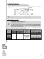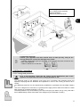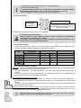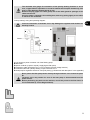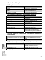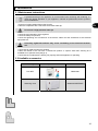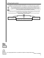
1
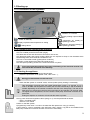
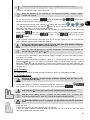
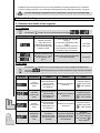
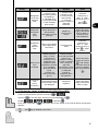
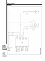
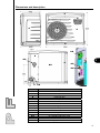
Installation instructions PF 6M-8M-11M-13M-15M Heat pump for swimming pool Réf. : N.C.003.B.EN - Ver. 12-2009 1. Installation............................................................................................ 2 1.1 Generals ............................................................................................................. 2 1.1.1 Cautions ..................................................................................................................... 2 1.1.2 General terms of delivery ........................................................................................... 2 1.1.3 Storage and transport conditions ............................................................................... 3 1.1.4 Field of application ..................................................................................................... 3 1.1.5 How it works ............................................................................................................... 3 1.2 Technical characteristics .................................................................................. 3 1.3 Operating conditions ......................................................................................... 4 1.4 Installation .......................................................................................................... 4 1.4.1 Access to technical compartment ............................................................................... 4 1.4.2 Selection of installation site ........................................................................................ 4 1.4.3 Installing the appliance ............................................................................................... 5 1.4.4 Hydraulic connections ................................................................................................ 5 1.4.5 Electric connections ................................................................................................... 6 1.5 Starting up .......................................................................................................... 9 1.5.1 Presentation of the regulation .................................................................................... 9 1.5.2 Checks before operating the appliance ...................................................................... 9 1.5.3 Starting the appliance ................................................................................................. 9 1.5.4 Checking .................................................................................................................. 10 1.5.5 Overwintering ........................................................................................................... 10 2. Troubleshooting ................................................................................ 11 2.1 Statuses and faults of the regulator ............................................................... 11 2.1.1 Statuses ................................................................................................................... 11 2.1.2 Faults ........................................................................................................................ 11 2.1.3 Display the values of sensors ST1-ST2-ST3 and ST4 ............................................. 12 2.2 Malfunctions of the appliance......................................................................... 13 2.2.1 The appliance does not work ................................................................................... 13 2.2.2 The appliance operates but the water temperature does not rise ............................ 13 2.2.3 The fan turns but the compressor stops from time to time without an error message appearing .......................................................................................................................... 13 2.2.4 The heat pump trips out or attempts to start itself from time to time ........................ 13 3. Maintenance ....................................................................................... 14 3.1 Maintenance instructions ................................................................................ 14 3.2 Available accessories...................................................................................... 14 3.3 Recycling the product ..................................................................................... 15 Available in the appendices at the end of the manual: - electric diagram - dimensions and description 1 1. Installation 1.1 Generals Carefully read this manual before installing, performing maintenance on or troubleshooting this device! The symbol indicates the presence of important information that must be taken into account to avoid injurying people or damaging the device. The symbol indicates the presence of useful information serving as a guideline. EN 1.1.1 Cautions This device must be installed and serviced by certified professionals qualified for electrical, hydraulic and refrigerating interventions. Before working on the appliance, ensure that the power supply is disconnected and secured, and that the function “priority heating” is disconnected. Do not vent R410A into atmosphere: R410A is a fluorinated greenhouse gas, covered by Kyoto Protocol, with a Global Warming Potential (GWP) = 1975 (Directive of the EC 842/2006). Elimination or shunting of one of the safety leads automatically to the cancellation of the guarantee, as for the replacement of parts by non-original parts. 1.1.2 General terms of delivery Any equipment, even CARRIAGE and PACKING FREE, travels at the consignee's risk. The consignee shall make reserves in writing on the carrier's delivery bill if he notes damage caused during the transport (confirmation to be sent to the carrier within 48 hours by registered mail and Acknowledgement of Receipt). The appliance must be transported upright on its pallet in its original packaging. If the appliance has been tipped over, express reserves in writing to the transporter. Contents: + + + Supplied parts (in a bag in the technical compartment, see §1.4.1): anti-vibration studs x5 + half union Ø50 fitting to stick x2 + gasket x 2 + M20 cable gland x1 2 1.1.3 Storage and transport conditions The appliance must be transported upright on its pallet. EN 1.1.4 Field of application Exclusive use: heating swimming pool water It must not be used for anything else. 1.1.5 How it works Compressor Air 15 °C Air 10 °C Condenser Evaporator Water 28 °C Water 26 °C Expansion valve condenstates Temperatures for information 1.2 Technical characteristics PF Single phase voltage Power Power consumed* restored* kW 6.6 Nominale current COP* consumption* A 6.25 4.9 Sound power* 6M 230V-50Hz kW 1.35 8M 230V-50Hz 1.59 7.8 7.3 4.9 65.2 37.2 52 11M 230V-50Hz 2.20 11 10.5 5 66.7 38.7 63 13M 230V-50Hz 2.83 13.3 13 4.7 65.1 37.1 68 65.1 37.1 81 3.10 15.5 15 5 15M 230V-50Hz * with an ambient air of +15 °C and a pool water of 24 °C, humidity 70% dBA 65.3 Sound pressure at Weight 10 meters* dBA Kg 37.3 51 unit protection class: IP 24 refrigerant gas: R410A refrigerant charge: see product name plate class : I, degree of pollution : 2, overvoltage category : II 3 1.3 Operating conditions Operating range: between 5 °C and 38 °C of air temperature between 5 °C and 32 °C of water temperature Maximum temperature limited at 32°C to protect the pool liner. 1.4 Installation EN Do not pick up the unit by the outside case, use the base to lift the unit. The installation and the hydraulic and electrical connections must be done to standards in force and especially standard NF C 15 100 for France (equivalent to EC I 364). 1.4.1 Access to technical compartment 1.4.2 Selection of installation site The appliance must be installed outdoors and must be surrounded by free space (see §1.4.4). the heat pump must be installed: - at a minimum distance from the end of the pool, as defined by the applicable national electrical standards. In France, the NF C 15 100 standard (section 702) specifies that this device must be installed more than 2 meters from any basin or water reserve. In case it may be subjected to water jets, provide for a minimum distance of 3.5 meters. the heat pump must not be installed: - near a source of heat or inflammable gas, - near a road with the risk of water and mud splashes, - facing a strong wind, - with the blowing towards a window or nearby wall, - with the blowing less than 4 metres from a permanent or temporary obstacle. Any bad installation can cause serious material or bodily damage (and can cause death). Keep the appliance out of the reach of children. 4 1.4.3 Installing the appliance installed the 5 anti-vibration studs (supplied, see §1.1.2), put onto a stable, solid (concrete slab type) and level surface, preserve from risks of flooding due to condensation produced by the appliance whilst it is operating (see §1.4.4) Fixing holes EN Possibility of fixing the appliance to the ground, using the holes in the base of the appliance. A diagram of drilling is available to the back of the packing box. 1.4.4 Hydraulic connections Water treatment, recommended parameters: - free chlorine: maximum 2.5 mg/l, - total bromine: maximum 5.5 mg/l, - pH : between 6.9 and 8.0. The water treatment system (chemical or electro-physical disinfection) must be installed downstream from the heat pump (see installation below), and must be compatible with it (check with the manufacturer). The connection shall be by Ø 50 PVC pressure pipe, from a by-pass , to the swimming pool filter circuit, after the filter and before the water treatment : Hydraulic circuit pressure PF test operating bar bar Fittings = inlet = outlet 6M 8M 11M 13M 15M 3 1.5 half union Ø50 fitting to stick (see parts and §1.1.2) Average water flow-rate head loss m³/h mCE 3 1.3 4 1.4 5 1.5 6 1.5 6.5 1.1 5 V1-V2-V3: by-pass valves V5-V4: setting valves (optional) *minimum distance electrical protection boxes EN Condensation drainage: Caution: your appliance can drain several litres of water per day, and you are strongly advised to connect the drainage to the sewer. connect a Ø18 interior pipe (not supplied), to the grooved end piece mounted on the base of the appliance, outlet: to the back or on the side : 1.4.5 Electric connections 1.4.5.1 Voltage and protection Prior to any operation, check that the voltage on the identification plate of the appliance corresponds to the mains voltage provided on site. the electrical supply of the appliance must come from a protection and switching device (not supplied) complying with the standards and regulations in force in the country (in France: NF C 15100). an additional protection may be required during installation to guarantee the overvoltage category II, the unit is designed for connection to a general power supply with full earth and neutral or neutral earth systems (in compliance with NF C 15-100), electrical protection: by circuit-breaker (curve D) or fuse (Am) (for calibre, see §1.4.5.3), and with a 30 mA differential trip switch at the head of the supply line (circuit-breaker or switch), 6 acceptable tolerance of tension variation: ± 6% (while working), electric cables shall be fixed, use cable suited for outdoor use, of type RO2V or equivalent in countries outside the European Community, and with an outer diameter between 9 and 18 mm, use the stuffing box to bring the supply cable into the appliance 1.4.5.2 Connections Earth terminal green/yellow Fuse holder F1 3.15 A Type T (timed) 250Vac Configuration of supply terminal rail single-phase 230V-50Hz with phase (L) + neutral (N) + Earth See placing § “dimensions and description” in the appendix The appliance must be earthed. Risk of electrical shock inside the device. Only a qualified and experienced technician can install the device’s cables. If the power cable is damaged, it must be replaced by a qualified technician or in a Zodiac Pool Care Europe technical station. 1.4.5.3 Cable sections supply cable section: for cables of a maximum length of 20 metres (calculation base: 5A/mm²), must be checked and adapted depending on installation conditions. PF 6M 8M 11M 13M 15M Maximum current consumption A 9 10 14.5 16.1 21.9 Cable saction mm² 3 x 2.5 3 x 2.5 3 x 2.5 3x4 3x6 3G2.5 3G2.5 3G2.5 3G4 3G6 Electrical protection A 16 16 16 20 25 1.4.5.4 “Priority Heating” function Objective: to keep the pool water at the required temperature, independent of the filtering time (the heat pump triggers the operation of the filter every hour): - the pool temperature > required temperature = the heat pump stops the filter system after 5 minutes. - the pool temperature < required temperature = the heat pump switches on and keeps the filter pump running until the correct temperature is attained. Main advantages offered by this function: - a guarantee that the heat pump operates long enough to attain the required temperature, in particular during initial warm-up periods (no longer necessary to manually switch on the filter system 24h/24). - constant control and monitoring of the pool heating requirements, even when the filter system has been switched off by the timer. Connection of the “priority heating” function: to use terminals 16 and 17 to come to control the pump of filtration using the dry contact (I max. = 5 has under 230Vac with circuit of class AC1 and I max. = 1,2A under 230Vac with circuit of class AC3), see diagram hereafter. The cable used for priority heating and the electrical power supply cable must be strapped together inside the unit until just after the stuffing box. 7 The minimum wire gauge for connection of the priority heating function is: 2x1.5 mm², of type RO2V or equivalent in countries outside the European Community, and with an outer diameter between 8 and 13 mm. Remove the plug (upper the cable gland) and fit the cable gland for passage of the cable into the unit. Once the cable is inserted in this stuffing box, block it by pulling lightly on the cable to retract it one centimeter. “Priority heating” wiring and operating diagram: Incorrect connection of terminals 16-17 may damage the regulator and renders the warranty invalid. Phase Phase F Neutral A1-A2: supply to power contactor coil of the filtering pump filter timer power contactor (3-pole or 2-pole), supplying the filter pump connection cable, wire gauge 2 x 1.5 mm² minimum (service voltage 300Vac) controller board with “priority heating” output, terminals 16-17 heat pump B1 regulation electronic card (see placing § “dimensions and description” in the appendix) Never power the filter pump motor directly through terminals 16-17 located on plate . Terminals 16-17 may remain live even if the heat pump is disconnected from the power source. Before performing any work on the machine, cut off the power to the filter timer at its circuit breaker (F on the diagram above). 8 EN 1.5 Starting up 1.5.1 Presentation of the regulation : controller “on” indicator : priority heating output enabled indicator : “on/off” or stand-by : display required water temperature or setting : setting values : compressor “on” (steady) or timed (blinking) indicator : defrost in progress (steady) or timed (blinking) indicator 1.5.2 Checks before operating the appliance the hydraulic connections are tight, the unit is stable (as well as level and upright), all cables are secure and all terminal connections are correct, the electrical supply and priority heating cables are not exposed to sharp or hot elements which could damage them, both inside and outside the unit, the unit is connected to earth (green/yellow conductor), not tools or other objects have been left inside the unit, the side panel providing access to the technical section is in place. Incorrectly tightened terminals may cause overheating of the electrical terminal rail, and causes the annulment of the warranty. 1.5.3 Starting the appliance recommendations to attain the required temperature: - protect the pool with a cover (blister cover, roller cover …), Strongly recommended to avoid heat loss. - switch the filter system to “manual” mode, 24h/24 (unless priority heating is connected), Take advantage of periods when the outside temperature is mild (> on average 10 °C) in order to facilitate the temperature increase (this can take several days, and its duration is variable depending on the weather conditions and size of the heat pump). The task of the heat pump is to extract the heat from the surrounding air and transfer it to the pool water. The higher the air temperature, the more heat the heat pump will be able to transfer to the pool water. Putting the setpoint on maximum will not heat the water any faster. the by-pass valves and regulation valves (see §1.4.4) must be positioned as follows: - valve 1 completely open, - valves 2-3-4-5 closed. switch on the filter system, progressively close valve 1 in order to increase the filter pressure to 150 g (0.150 bar), open valves 2, 3 and 4 completely, then half open valve 5 (see §1.4.4) (the air accumulated in the heat pump condenser unit and in the filter circuit is then evacuated), 9 If valves 4 and 5 are not present, open valve 2 completely and half close valve 3. switch on the electrical supply to the heat pump, When the regulator is first switched on, the following information messages appear: “REXX” then “MAPX”. if the heat pump is in stand-by: , press 3 seconds on seconds and then the water temperature is displayed. , appears for 5 set the temperature to the value required (= set point) with the buttons + or + ) => If the pool requires heating, the indicator blinks for 2 to 3 minutes then remains on and the heat pump compressor + fan start up at the same time. during the first 5 minutes of compressor and fan operation, the 3 coloured bars located left of the display blink , then only one bar remains on. This indicates whether the water flow-rate through the heat pump is: too low (red bar), correct (green bar) or too high (red bar). if the regulator detects that the flow-rate is too low or too high, valve 5 (or 3 if 5 is not present) must be adjusted until the green middle bar lights up. During this adjustment phase, wait 30 seconds after each valve position change as the regulator response time is not instantaneous. Once the pool has attained the required temperature, the heat pump switches off automatically (indicators and off) in case of mains power failure, when the power supply is restored, the heat pump starts up after a time period of 2 minutes. when the ambient temperature is between 5 and 12 °C, the heat pump may start a defrost cycle (indicators and on). In this case, the compressor stops but the fan keeps running in order to defrost the evaporator with the ambient air. Once the end of defrost cycle has been detected, The compressor and fan restart after a time period of 2 to 5 minutes (varies according to the compressor stoppage time). 1.5.4 Checking The heat pump must switch off when filtering is stopped or valve 2 (or 4 if present) is closed. 1.5.5 Overwintering Wintering is essential, on pain of the condenser freezing, and this case is not covered by the warranty. switch the regulator to “stand-by” mode by pressing and holding for 3 seconds on then appears on the screen for 5 seconds before a small red dot appears If the indicator , , is on, it will remain on for 2 minutes before switching off. With the priority heating function connected, the filter remains on for 2 minutes, after switching the heat pump to “stand-by” (outside the programmed filter periods). If a heat pump defrost cycle is in progress: the fan remains on until the end of this cycle. open the valve 1, close valves 2 and 3, and open valves 4 and 5 (if present), drain the water condenser (risk of frost) by removing the two pool water inlet and outlet connections at the back of the heat pump, 10 EN retighten these connections one turn to avoid penetration of foreign bodies into the condenser, cover the heat pump with a micro-breathing overwintering cover (optional accessory, see §3.2). To avoid damaging the appliance with condensation, do not cover it hermetically. 2. Troubleshooting 2.1 Statuses and faults of the regulator 2.1.1 Statuses The indicator remains on for 2 minutes after the message Display (alternating with ) or Cause Solution Reset 1 - filtration pump off 2 – water flow in the appliance not enough, 3- flow switch defective or disconnected. 1- clean the filter and start the filtering 2- check the adjustment of the valves, 3- test the continuity of the flow switch and the connection of terminals 7 and 8 of card B1 Automatic after timer Outside temperature too low (ST2 < to + 5 °C) for probe reading, see §2.1.3 Wait for the outside temperature to increase naturally Automatic 2.1.2 Faults The indicator remains on for 2 minutes after one of the messages indicated above. The fault of the heat pump. Display , alternating with the pool water temperature, does not block operation Designation Cause Solution Control sensor fault (ST1) Sensor defective or disconnected (terminals 2-3 of the plate B1) Replace or reconnect the sensor Antifreeze sensor fault (ST2) Sensor defective or disconnected (terminals 1-3 of the plate B1) Replace or reconnect the sensor Defrost sensor fault (ST3) Sensor defective or disconnected (terminals 4-6 of the plate B1) Replace or reconnect the sensor Refrigerant circuit low pressure fault Insufficient refrigerant (if the fault persists after clearing) Contact an approved technician to detect the leak and top up the refrigerant Reset Switch the power supply off or press if “dSr” flashes Switch the power supply off or press if “dSA” flashes Switch the power supply off or press if “dSd” flashes Automatic (if less than 4 “dbP” or “dHP” faults per hour) or press if “dbP” flashes 11 Display (alternating with ) Designation Cause Solution Refrigerant circuit high pressure fault 1- emulsion of air and water passed in the appliance, 2- bad water flow, 3- exchanger fouled 4- flow controller jammed shut 1 - check the pool hydraulic circuit 2 - check the flow rate controler 3 - if the fault persists, contact an approved technician Sensor defective or disconnected (terminals 4-5 of the plate B1) Replace or reconnect the sensor Water flowrate sensor fault (ST4) Refrigerant circuit pressure fault High or low pressure fault tripped while fault “ESt4” Cancel the fault “ESt4” Defrost cycle time exceeded Defrost cycle too long (> 1 hour): - excessive ice formation on the evaporator (low temperature with evaporator blocked or no ventilation during the defrost cycle). - incorrect ST3 sensor value (see §2.1.3) Cancel the fault, then check that the defrost cycle operates correctly. In case of repeated fault: contact an approved technician to check for the presence of an adequate quantity of refrigerant gas in the appliance. The parameters data in the controller chips are damaged Change the regulator EEPROM fault (microprocessor) Reset Automatic (if less than 4 “dbP” or “dHP” faults per hour) or if press “dHP” flashes EN Switch the power supply off and then back on again or automatic if the fault disappears. Automatic (if less than 4 “dbP” or “dHP” faults per hour) or press if “ESt4” flashes Switch the power supply off or press if “dtd” flashes (case after stand-by following regulator start up by pressing ) Switch the power supply off and then back on again 2.1.3 Display the values of sensors ST1-ST2-ST3 and ST4 enter into the parameter: press 3 seconds on press on display to view the value, and return by pressing again on => quit: press 3 seconds on regulator. - the => => by pressing , . or automatic after a time period of 70 seconds without touching the key is disabled in this menu. 12 2.2 Malfunctions of the appliance 2.2.1 The appliance does not work Causes Verification / solution No display Check the supply voltage and the fuse The pool temperature is above the temperature setpoint. Increase the temperature setpoint. A message is on the screen. Check the meaning of message §2.1 2.2.2 The appliance operates but the water temperature does not rise Causes Verification / solution Not enough filtering time Put the filtering on manual 24/24 hours to raise the temperature. Non-complying period of use Check whether the heat pump is of the right dimension for this period of the year. The heat pump is under-dimensioned. Check the characteristics of the heat pump according to the pool. The automatic pool water filler is jammed in open position. Checking correct operation of the automatic filler. The heat insulating cover is not used. Put on the heat insulating cover. The evaporator is fouled. Clean the evaporator (see §3.1) The appliance is badly installed. The appliance must be installed outdoors. Make sure there is no obstacle less than 4 metres from where the blower is facing, and 0.50 metre behind the heat pump. 2.2.3 The fan turns but the compressor stops from time to time without an error message appearing Causes Verification / solution The heat pump does defrosting cycles from time to time. Normal if the outside temperature is lower than 12 °C. The evaporator is fouled. Clean the evaporator. 2.2.4 The heat pump trips out or attempts to start itself from time to time Causes Verification / solution The circuit breaker is under dimensioned or badly dimensioned. Check the circuit breaker (see § 1.4.5.1). The cable section is to small. Check the cable section (see §1.4.5.3) The supply voltage is to low. Call your electricity board. 13 3. Maintenance 3.1 Maintenance instructions A general servicing of the appliance is recommended when wintering and restarting, to check the proper operation of your appliance, maintain its performance and to prevent some breakdowns. ensure no foreign bodies obstruct the fan grid, clean the evaporator with a soft brush and a fresh water jet, EN Do not use a high-pressure water jet. check the good operation of the regulator, check the safety components, check the tightening and connections of the electric cables and the cleanliness of the electrical equipment box, Incorrectly tightened terminals may cause overheating of the electrical terminal rail. check that all metal elements are earthed, clean the outside of the unit with a solvent-free product. A specific PAC NET cleaning kit is available as an optional extra (see §3.2), check that the condensation is flowing out properly whilst the appliance is operating. 3.2 Available accessories Naming Representation Item code PAC NET WMA03491 Wintering cover W20HOUSSEPFIRST 14 3.3 Recycling the product Your appliance is reaching the end of its working life. You would like to get rid of it or replace it. Please do not throw it into the dustbin or into your local council’s selective sorting containers. When this symbol appears on a new appliance, it means that the equipment must not be thrown away and that it will be collected selectively so that it can be reused, recycled or recovered. Any substances it may contain which are potentially dangerous to the environment will be eliminated or neutralised. You can give it to a community association who will be able to repair it and put it back into circulation. If you buy a new one, you can take the old one to the store or ask the delivery man to take it back. This is known as a “One-for-One” exchange. Otherwise please take it to a waste collection centre, if your local council has set up a selective collection system for these products. Give the appliance to a community. Take the used device back to the distributor when making a new purchase. Take the used device to a waste. For ongoing improvement, our products are subject to change without notice. Version of 12/2009 B 15 CONFORMITY CERTIFICATE Z.P.C.E. declares that the herewith products or ranges: Swimming pool Heat pumps: Power First 6M-8M-11M-13M-15M are in conformity with the provisions: of the ELECTROMAGNETIC COMPATIBILITY directive 2004/108/EC. of the LOW VOLTAGE directive 2006/95/EC. ADDITIONAL RECOMMENDATIONS In relation with the Pressurised Equipment Directive (PED-97/23/CE) 1. Installation and maintenance before beginning any installation, commissioning, operation or maintenance work, the persons responsible for these tasks must have read and understood all instructions and recommendations contained in the unit installation instructions as well as in the project technical file. the person responsible for final acceptance of the unit must carry out a visual inspection to detect any damage the unit may have suffered during transport: refrigeration circuit, electrical enclosure, frame and casing. the unit may not be installed close to: - a heat source, - combustible materials, - the air duct inlet of an adjacent building. for certain appliances, it is essential to fit protection grids if the unit is installed in an area which is unprotected and easily accessible. the appliance may only be installed, commissioned, serviced and repaired by properly qualified persons in accordance with directives, laws, valid regulations and acceptable professional practice. during installation, repair and maintenance work, it is strictly prohibited to step on pipes and hoses as these could break and the escaping refrigerant could cause serious scalding. when servicing the appliance, the composition and state of heat carrying fluid must be checked, as well as the absence of any refrigerant. during the annual unit sealing test in accordance with valid legislation, the high and low pressure switches must be checked to ensure they are securely fastened to the refrigeration circuit and that they shut-off the electrical circuit when tripped. during maintenance work, ensure there are no traces of corrosion or oil around refrigeration components. before beginning work on the refrigeration circuit, isolate the appliance and wait several minutes before removing the temperature or pressure sensors. Certain elements such as the compressor and associated piping may attain temperatures in excess of 100°C and high pressures with the consequent risk of severe scalding. 2. Repair all work on the refrigeration circuit must be carried out with total respect of valid safety regulations and acceptable professional practice: recuperation of refrigerant, nitrogen brazing, etc… all brazing work must be carried out by a qualified brazer/welder, in the case of units filled with R410A, refer to the specific indications in the installation instructions. this unit contains pressurized components, some of which may be manufactured by ZPCE, this is the case of piping elements. Only use the original spare parts indicated in the spare parts list to replace a defective refrigeration component replacement pipes must always be made of copper in compliance with standard NF EN 12735-1. leak detection, pressure test: - never use oxygen or dry air, risk of fire or explosion, - use dry nitrogen or the mixture of nitrogen and refrigerant indicated on the name plate, - the test pressure for both the high and low pressure circuits must not exceed 42 bar. the high pressure circuit pipes are made of copper and have a diameter equal to or greater than 1’’5/8. A certificate as indicated in §2.1 in compliance with standard NF EN 10204 will be requested from the supplier and filed in the installation technical documentation. the use of non-original spare parts, modifications to the refrigeration circuit, replacement of the refrigerant with a refrigerant type other than that indicated on the name plate, use of the appliance under conditions outside the application limits indicated in the associated documentation will result in a cancellation of the EC label and PED conformity and the person who carried out these modifications will be sole responsible for the consequences. the technical data relative to the safety requirements of the various applicable directives must be indicated on the name plate. This data must be recorded in the unit installation instructions which are included in the installation technical file: - model – code – serial number, - maximum and minimum OT, - OP, - year of manufacture, - EC label, - manufacturer’s address, - refrigerant and weight, - electrical parameters, - thermo-dynamic and acoustic performance Electric diagram PF 6M-8M * 1 PF 11M-13M-15M * 2 3 Flow rate controler Regulation sensor NTC Antifreeze sensor Defrost sensor NTC Water flow adjusting probe NTC Regulation electronic card J1 SD1 SD2 SD3 SD4 B1 Grey White Pink G Bl R Soft starter Soft starter Brown Compressor M2 M Fan M1 Blue Fan connector CX1 B Compressor capacitor C2 Black Fan capacitor C1 N Fuse 3.15A T 250V 5/20 F1 Pump control Low pressure switch E21 16-17 High pressure switch Earth Power supply 230V-1N-50Hz E2 L-N English Dimensions and description * English Base Front pannel cowl Technical door Back pannel Post Grid Regulator Ø1” ½ water pool inlet Ø1” ½ water pool outlet Evaporator Stuffing box B1 regulation electronic card Fuse F1 Supply terminal board 4 N o t e s - N o t e n - A a n t e k e n i n g - N o t a s - N o t a N o t e s - N o t e n - A a n t e k e n i n g - N o t a s - N o t a Plaque signalétique – Product name plate Votre installateur – Your installer Chauffage et déshumidification de piscines – Heating and dehumidification of pools Zodiac Pool Care Europe – Boulevard de la Romanerie – BP 90023 49180 Saint Barthélémy d’Anjou cedex – France www.zodiac-poolcare.com Global provider of innovative pool products and services Produits et services innovants pour la piscine