1
MITSUBISHI ELECTRIC
MELSEC Q Series
Motion Controllers
Programming Manual
SV22 (VIRTUAL MODE)
Q172HCPU
Q173HCPU
Art. no: 201817
IB(NA)-0300114-B
01092006
Version B
MITSUBISHI ELECTRIC
INDUSTRIAL AUTOMATION
SAFETY PRECAUTIONS
(Read these precautions before using.)
When using this equipment, thoroughly read this manual and the associated manuals introduced in this
manual. Also pay careful attention to safety and handle the module properly.
These precautions apply only to this equipment. Refer to the Q173HCPU/Q172HCPU Users manual for a
description of the Motion controller safety precautions.
These SAFETY PRECAUTIONS classify the safety precautions into two categories: "DANGER" and
"CAUTION".
DANGER
Indicates that incorrect handling may cause hazardous conditions,
resulting in death or severe injury.
! CAUTION
Indicates that incorrect handling may cause hazardous conditions,
resulting in medium or slight personal injury or physical damage.
!
Depending on circumstances, procedures indicated by ! CAUTION may also be linked to serious
results.
In any case, it is important to follow the directions for usage.
Store this manual in a safe place so that you can take it out and read it whenever necessary. Always
forward it to the end user.
A-1
For Safe Operations
1. Prevention of electric shocks
DANGER
!
Never open the front case or terminal covers while the power is ON or the unit is running, as this
may lead to electric shocks.
Never run the unit with the front case or terminal cover removed. The high voltage terminal and
charged sections will be exposed and may lead to electric shocks.
Never open the front case or terminal cover at times other than wiring work or periodic
inspections even if the power is OFF. The insides of the Motion controller and servo amplifier are
charged and may lead to electric shocks.
When performing wiring work or inspections, turn the power OFF, wait at least ten minutes, and
then check the voltage with a tester, etc.. Failing to do so may lead to electric shocks.
Be sure to ground the Motion controller, servo amplifier and servomotor. (Ground resistance :
100 or less) Do not ground commonly with other devices.
The wiring work and inspections must be done by a qualified technician.
Wire the units after installing the Motion controller, servo amplifier and servomotor. Failing to do
so may lead to electric shocks or damage.
Never operate the switches with wet hands, as this may lead to electric shocks.
Do not damage, apply excessive stress, place heavy things on or sandwich the cables, as this
may lead to electric shocks.
Do not touch the Motion controller, servo amplifier or servomotor terminal blocks while the power
is ON, as this may lead to electric shocks.
Do not touch the built-in power supply, built-in grounding or signal wires of the Motion controller
and servo amplifier, as this may lead to electric shocks.
2. For fire prevention
!
CAUTION
Install the Motion controller, servo amplifier, servomotor and regenerative resistor on inflammable
material. Direct installation on flammable material or near flammable material may lead to fire.
If a fault occurs in the Motion controller or servo amplifier, shut the power OFF at the servo
amplifier’s power source. If a large current continues to flow, fire may occur.
When using a regenerative resistor, shut the power OFF with an error signal. The regenerative
resistor may abnormally overheat due to a fault in the regenerative transistor, etc., and may lead
to fire.
Always take heat measures such as flame proofing for the inside of the control panel where the
servo amplifier or regenerative resistor is installed and for the wires used. Failing to do so may
lead to fire.
A-2
3. For injury prevention
!
CAUTION
Do not apply a voltage other than that specified in the instruction manual on any terminal.
Doing so may lead to destruction or damage.
Do not mistake the terminal connections, as this may lead to destruction or damage.
Do not mistake the polarity ( + / - ), as this may lead to destruction or damage.
Do not touch the servo amplifier's heat radiating fins, regenerative resistor and servomotor, etc.,
while the power is ON and for a short time after the power is turned OFF. In this timing, these
parts become very hot and may lead to burns.
Always turn the power OFF before touching the servomotor shaft or coupled machines, as these
parts may lead to injuries.
Do not go near the machine during test operations or during operations such as teaching.
Doing so may lead to injuries.
4. Various precautions
Strictly observe the following precautions.
Mistaken handling of the unit may lead to faults, injuries or electric shocks.
(1) System structure
!
CAUTION
Always install a leakage breaker on the Motion controller and servo amplifier power source.
If installation of an electromagnetic contactor for power shut off during an error, etc., is specified in
the instruction manual for the servo amplifier, etc., always install the electromagnetic contactor.
Install the emergency stop circuit externally so that the operation can be stopped immediately and
the power shut off.
Use the Motion controller, servo amplifier, servomotor and regenerative resistor with the combinations listed in the instruction manual. Other combinations may lead to fire or faults.
If safety standards (ex., robot safety rules, etc.,) apply to the system using the Motion controller,
servo amplifier and servomotor, make sure that the safety standards are satisfied.
Construct a safety circuit externally of the Motion controller or servo amplifier if the abnormal
operation of the Motion controller or servo amplifier differ from the safety directive operation in the
system.
In systems where coasting of the servomotor will be a problem during the forced stop, emergency
stop, servo OFF or power supply OFF, use dynamic brakes.
Make sure that the system considers the coasting amount even when using dynamic brakes.
In systems where perpendicular shaft dropping may be a problem during the forced stop,
emergency stop, servo OFF or power supply OFF, use both dynamic brakes and electromagnetic
brakes.
The dynamic brakes must be used only on errors that cause the forced stop, emergency stop, or
servo OFF. These brakes must not be used for normal braking.
A-3
!
CAUTION
The brakes (electromagnetic brakes) assembled into the servomotor are for holding applications,
and must not be used for normal braking.
The system must have a mechanical allowance so that the machine itself can stop even if the
stroke limits switch is passed through at the max. speed.
Use wires and cables that have a wire diameter, heat resistance and bending resistance
compatible with the system.
Use wires and cables within the length of the range described in the instruction manual.
The ratings and characteristics of the parts (other than Motion controller, servo amplifier and
servomotor) used in a system must be compatible with the Motion controller, servo amplifier and
servomotor.
Install a cover on the shaft so that the rotary parts of the servomotor are not touched during
operation.
There may be some cases where holding by the electromagnetic brakes is not possible due to the
life or mechanical structure (when the ball screw and servomotor are connected with a timing belt,
etc.). Install a stopping device to ensure safety on the machine side.
(2) Parameter settings and programming
!
CAUTION
Set the parameter values to those that are compatible with the Motion controller, servo amplifier,
servomotor and regenerative resistor model and the system application. The protective functions
may not function if the settings are incorrect.
The regenerative resistor model and capacity parameters must be set to values that conform to
the operation mode, servo amplifier and servo power supply module. The protective functions
may not function if the settings are incorrect.
Set the mechanical brake output and dynamic brake output validity parameters to values that are
compatible with the system application. The protective functions may not function if the settings
are incorrect.
Set the stroke limit input validity parameter to a value that is compatible with the system
application. The protective functions may not function if the setting is incorrect.
Set the servomotor encoder type (increment, absolute position type, etc.) parameter to a value
that is compatible with the system application. The protective functions may not function if the
setting is incorrect.
Set the servomotor capacity and type (standard, low-inertia, flat, etc.) parameter to values that
are compatible with the system application. The protective functions may not function if the
settings are incorrect.
Set the servo amplifier capacity and type parameters to values that are compatible with the
system application. The protective functions may not function if the settings are incorrect.
Use the program commands for the program with the conditions specified in the instruction
manual.
A-4
!
CAUTION
Set the sequence function program capacity setting, device capacity, latch validity range, I/O
assignment setting, and validity of continuous operation during error detection to values that are
compatible with the system application. The protective functions may not function if the settings
are incorrect.
Some devices used in the program have fixed applications, so use these with the conditions
specified in the instruction manual.
The input devices and data registers assigned to the link will hold the data previous to when
communication is terminated by an error, etc. Thus, an error correspondence interlock program
specified in the instruction manual must be used.
Use the interlock program specified in the special function module's instruction manual for the
program corresponding to the special function module.
(3) Transportation and installation
!
CAUTION
Transport the product with the correct method according to the mass.
Use the servomotor suspension bolts only for the transportation of the servomotor. Do not
transport the servomotor with machine installed on it.
Do not stack products past the limit.
When transporting the Motion controller or servo amplifier, never hold the connected wires or
cables.
When transporting the servomotor, never hold the cables, shaft or detector.
When transporting the Motion controller or servo amplifier, never hold the front case as it may fall
off.
When transporting, installing or removing the Motion controller or servo amplifier, never hold the
edges.
Install the unit according to the instruction manual in a place where the mass can be withstood.
Do not get on or place heavy objects on the product.
Always observe the installation direction.
Keep the designated clearance between the Motion controller or servo amplifier and control panel
inner surface or the Motion controller and servo amplifier, Motion controller or servo amplifier and
other devices.
Do not install or operate Motion controller, servo amplifiers or servomotors that are damaged or
that have missing parts.
Do not block the intake/outtake ports of the servomotor with cooling fan.
Do not allow conductive matter such as screw or cutting chips or combustible matter such as oil
enter the Motion controller, servo amplifier or servomotor.
The Motion controller, servo amplifier and servomotor are precision machines, so do not drop or
apply strong impacts on them.
A-5
!
CAUTION
Securely fix the Motion controller and servo amplifier to the machine according to the instruction
manual. If the fixing is insufficient, these may come off during operation.
Always install the servomotor with reduction gears in the designated direction. Failing to do so
may lead to oil leaks.
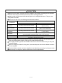
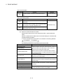
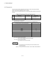
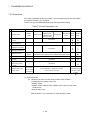
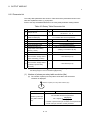
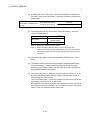
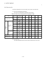
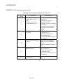
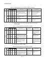
Store and use the unit in the following environmental conditions.
Environment
Ambient
temperature
Ambient humidity
Storage
temperature
Atmosphere
Conditions
Motion controller/Servo amplifier
According to each instruction manual.
According to each instruction manual.
According to each instruction manual.
Servomotor
0°C to +40°C (With no freezing)
(32°F to +104°F)
80% RH or less
(With no dew condensation)
-20°C to +65°C
(-4°F to +149°F)
Indoors (where not subject to direct sunlight).
No corrosive gases, flammable gases, oil mist or dust must exist
Altitude
1000m (3280.84ft.) or less above sea level
Vibration
According to each instruction manual
When coupling with the synchronization encoder or servomotor shaft end, do not apply impact
such as by hitting with a hammer. Doing so may lead to detector damage.
Do not apply a load larger than the tolerable load onto the servomotor shaft. Doing so may lead
to shaft breakage.
When not using the module for a long time, disconnect the power line from the Motion controller
or servo amplifier.
Place the Motion controller and servo amplifier in static electricity preventing vinyl bags and store.
When storing for a long time, please contact with our sales representative.
A-6
(4) Wiring
!
CAUTION
Correctly and securely wire the wires. Reconfirm the connections for mistakes and the terminal
screws for tightness after wiring. Failing to do so may lead to run away of the
servomotor.
After wiring, install the protective covers such as the terminal covers to the original positions.
Do not install a phase advancing capacitor, surge absorber or radio noise filter (option FR-BIF)
on the output side of the servo amplifier.
Correctly connect the output side (terminals U, V, W). Incorrect connections will lead the
servomotor to operate abnormally.
Do not connect a commercial power supply to the servomotor, as this may lead to trouble.
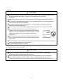
Do not mistake the direction of the surge absorbing diode
Servo amplifier
installed on the DC relay for the control signal output of brake
VIN
signals, etc. Incorrect installation may lead to signals not being
(24VDC)
output when trouble occurs or the protective functions not
functioning.
Control output
RA
signal
Do not connect or disconnect the connection cables between
each unit, the encoder cable or PLC expansion cable while the
power is ON.
Securely tighten the cable connector fixing screws and fixing mechanisms. Insufficient fixing may
lead to the cables combing off during operation.
Do not bundle the power line or cables.
(5) Trial operation and adjustment
!
CAUTION
Confirm and adjust the program and each parameter before operation. Unpredictable
movements may occur depending on the machine.
Extreme adjustments and changes may lead to unstable operation, so never make them.
When using the absolute position system function, on starting up, and when the Motion
controller or absolute value motor has been replaced, always perform a home position return.
A-7
(6) Usage methods
!
CAUTION
Immediately turn OFF the power if smoke, abnormal sounds or odors are emitted from the Motion
controller, servo amplifier or servomotor.
Always execute a test operation before starting actual operations after the program or
parameters have been changed or after maintenance and inspection.
The units must be disassembled and repaired by a qualified technician.
Do not make any modifications to the unit.
Keep the effect or electromagnetic obstacles to a minimum by installing a noise filter or by using
wire shields, etc. Electromagnetic obstacles may affect the electronic devices used near the
Motion controller or servo amplifier.
When using the CE Mark-compliant equipment, refer to the "EMC Installation Guidelines" (data
number IB(NA)-67339) for the Motion controllers and refer to the corresponding EMC guideline
information for the servo amplifiers, inverters and other equipment.
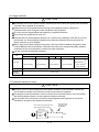
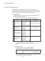
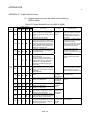
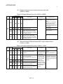
Use the units with the following conditions.
Item
Conditions
Q61P-A1
100 to 120VAC
Q61P-A2
+10%
-15%
200 to 240VAC
Q61P
+10%
-15%
Q62P
100 to 240VAC
+10%
-15%
Q63P
24VDC
Q64P
+30%
-35%
100 to 120VAC
200 to 240VAC
Input power
(85 to 132VAC)
(170 to 264VAC)
(85 to 264VAC)
Input frequency
50/60Hz ±5%
Tolerable
momentary
power failure
20ms or less
(15.6 to 31.2VDC)
+10%
-15%
+10%
-15%
(85 to 132VAC/
170 to 264VAC)
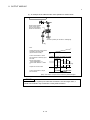
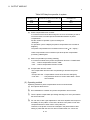
(7) Corrective actions for errors
!
CAUTION
If an error occurs in the self diagnosis of the Motion controller or servo amplifier, confirm the
check details according to the instruction manual, and restore the operation.
If a dangerous state is predicted in case of a power failure or product failure, use a servomotor
with electromagnetic brakes or install a brake mechanism externally.
Use a double circuit construction so that the electromagnetic brake operation circuit can be
operated by emergency stop signals set externally.
Shut off with servo ON signal OFF,
alarm, magnetic brake signal.
Servomotor
RA1
Electromagnetic
brakes
Shut off with the
emergency stop
signal(EMG).
EMG
24VDC
A-8
/
!
CAUTION
If an error occurs, remove the cause, secure the safety and then resume operation after alarm
release.
The unit may suddenly resume operation after a power failure is restored, so do not go near the
machine. (Design the machine so that personal safety can be ensured even if the machine
restarts suddenly.)
(8) Maintenance, inspection and part replacement
!
CAUTION
Perform the daily and periodic inspections according to the instruction manual.
Perform maintenance and inspection after backing up the program and parameters for the Motion
controller and servo amplifier.
Do not place fingers or hands in the clearance when opening or closing any opening.
Periodically replace consumable parts such as batteries according to the instruction manual.
Do not touch the lead sections such as ICs or the connector contacts.
Do not place the Motion controller or servo amplifier on metal that may cause a power leakage or
wood, plastic or vinyl that may cause static electricity buildup.
Do not perform a megger test (insulation resistance measurement) during inspection.
When replacing the Motion controller or servo amplifier, always set the new module settings
correctly.
When the Motion controller or absolute value motor has been replaced, carry out a home position
return operation using one of the following methods, otherwise position displacement could occur.
1) After writing the servo data to the Motion controller using programming software, switch on the
power again, then perform a home position return operation.
2) Using the backup function of the programming software, load the data backed up before
replacement.
After maintenance and inspections are completed, confirm that the position detection of the
absolute position detector function is correct.
Do not short circuit, charge, overheat, incinerate or disassemble the batteries.
The electrolytic capacitor will generate gas during a fault, so do not place your face near the
Motion controller or servo amplifier.
The electrolytic capacitor and fan will deteriorate. Periodically replace these to prevent secondary
damage from faults. Replacements can be made by our sales representative.
A-9
(9) About processing of waste
When you discard Motion controller, servo amplifier, a battery (primary battery) and other option articles,
please follow the law of each country (area).
!
CAUTION
This product is not designed or manufactured to be used in equipment or systems in situations
that can affect or endanger human life.
When considering this product for operation in special applications such as machinery or systems
used in passenger transportation, medical, aerospace, atomic power, electric power, or
submarine repeating applications, please contact your nearest Mitsubishi sales representative.
Although this product was manufactured under conditions of strict quality control, you are strongly
advised to install safety devices to forestall serious accidents when it is used in facilities where a
breakdown in the product is likely to cause a serious accident.
(10) General cautions
!
CAUTION
All drawings provided in the instruction manual show the state with the covers and safety
partitions removed to explain detailed sections. When operating the product, always return the
covers and partitions to the designated positions, and operate according to the instruction manual.
A - 10
REVISIONS
The manual number is given on the bottom left of the back cover.
Print Date
Jun., 2005
Sep., 2006
Manual Number
Revision
IB(NA)-0300114-A First edition
IB(NA)-0300114-B [Additional model]
Q61P, MR-J3- B(Large capacity), MR-J3- B-RJ006
[Additional function]
Control loop changing command, Control loop monitor status
[Additional correction/partial correction]
About Manuals, Device lists, Error codes, etc.
Japanese Manual Number IB(NA)-0300094
This manual confers no industrial property rights or any rights of any other kind, nor does it confer any patent
licenses. Mitsubishi Electric Corporation cannot be held responsible for any problems involving industrial property
rights which may occur as a result of using the contents noted in this manual.
© 2005 MITSUBISHI ELECTRIC CORPORATION
A - 11
INTRODUCTION
Thank you for choosing the Q173HCPU/Q172HCPU Motion Controller.
Please read this manual carefully so that equipment is used to its optimum.
CONTENTS
Safety Precautions .........................................................................................................................................A- 1
Revisions ........................................................................................................................................................A-11
Contents .........................................................................................................................................................A-12
About Manuals ...............................................................................................................................................A-15
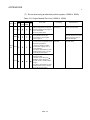
1. OVERVIEW
1- 1 to 1- 4
1.1 Overview................................................................................................................................................... 1- 1
1.2 Motion Control in SV13/SV22 Real Mode............................................................................................... 1- 3
1.3 Motion Control in SV22 Virtual Mode ...................................................................................................... 1- 4
2. STARTING UP THE MULTIPLE CPU SYSTEM
2- 1 to 2- 8
2.1 Starting Up the System ............................................................................................................................ 2- 1
2.2 Differences Between Incremental System and Absolute System .......................................................... 2 - 3
2.2.1 Operation for incremental system..................................................................................................... 2 - 3
2.2.2 Operation for absolute (absolute position) system........................................................................... 2 - 4
2.3 Differences Between Real Mode and Virtual Mode................................................................................ 2 - 5
2.3.1 Positioning data................................................................................................................................. 2 - 5
2.3.2 Positioning devices............................................................................................................................ 2 - 5
2.3.3 Servo programs................................................................................................................................. 2 - 6
2.3.4 Control change (Current value change/speed change)................................................................... 2 - 7
3. PERFORMANCE SPECIFICATIONS
3- 1 to 3- 2
4. POSITIONING DEDICATED SIGNALS
4- 1 to 4-92
4.1 Internal Relays ......................................................................................................................................... 4- 2
4.1.1 Axis statuses ..................................................................................................................................... 4-17
4.1.2 Axis command signals ...................................................................................................................... 4-24
4.1.3 Virtual servomotor axis statuses....................................................................................................... 4-28
4.1.4 Virtual servomotor axis command signals ...................................................................................... 4-33
4.1.5 Synchronous encoder axis statuses ............................................................................................... 4-38
4.1.6 Synchronous encoder axis command signals.................................................................................. 4-40
4.1.7 Cam axis command signals.............................................................................................................. 4-41
4.1.8 Smoothing clutch complete signals .................................................................................................. 4-42
4.1.9 Common devices .............................................................................................................................. 4-44
4.2 Data Registers.......................................................................................................................................... 4-59
4.2.1 Axis monitor devices ......................................................................................................................... 4-67
4.2.2 Control change registers................................................................................................................... 4-69
4.2.3 Virtual servomotor axis monitor devices........................................................................................... 4-70
A - 12
4.2.4 Current value after virtual servomotor axis main shaft's differential gear ....................................... 4-72
4.2.5 Synchronous encoder axis monitor devices..................................................................................... 4-74
4.2.6 Current value after synchronous encoder axis main shaft's differential gear ................................. 4-75
4.2.7 Cam axis monitor devices................................................................................................................. 4-77
4.2.8 Common devices .............................................................................................................................. 4-78
4.3 Motion registers(#) ................................................................................................................................... 4-82
4.4 Special relays (SP.M) .............................................................................................................................. 4-83
4.5 Special registers (SP.D)........................................................................................................................... 4-85
5. MECHANICAL SYSTEM PROGRAM
5- 1 to 5- 6
5.1 Mechanical Module Connection Diagram ............................................................................................... 5- 2
5.2 Mechanical Module List ........................................................................................................................... 5- 5
6. DRIVE MODULE
6- 1 to 6-26
6.1 Virtual Servomotor ................................................................................................................................... 6- 1
6.1.1 Operation description ........................................................................................................................ 6- 1
6.1.2 Parameter list .................................................................................................................................... 6-11
6.1.3 Virtual servomotor axis devices (Internal relays, data registers)..................................................... 6-16
6.2 Synchronous Encoder.............................................................................................................................. 6-17
6.2.1 Operation description ........................................................................................................................ 6-17
6.2.2 Parameter list .................................................................................................................................... 6-21
6.2.3 Synchronous encoder axis devices (Internal relays, data registers)............................................... 6-22
6.3 Virtual Servomotor/Synchronous Encoder Control Change................................................................... 6-23
6.3.1 Virtual servomotor control change.................................................................................................... 6-23
6.3.2 Synchronous encoder control change.............................................................................................. 6-25
7. TRANSMISSION MODULE
7- 1 to 7-38
7.1 Gear.......................................................................................................................................................... 7- 3
7.1.1 Operation ........................................................................................................................................... 7- 3
7.1.2 Parameters ........................................................................................................................................ 7- 3
7.2 Clutch........................................................................................................................................................ 7- 5
7.2.1 Operation ........................................................................................................................................... 7-11
7.2.2 Parameters ........................................................................................................................................ 7-28
7.3 Speed Change Gear ................................................................................................................................ 7-34
7.3.1 Operation ........................................................................................................................................... 7-34
7.3.2 Parameters ........................................................................................................................................ 7-35
7.4 Differential Gear ....................................................................................................................................... 7-37
7.4.1 Operation ........................................................................................................................................... 7-37
7.4.2 Parameters (Must be not set) ........................................................................................................... 7-37
8. OUTPUT MODULE
8- 1 to 8-38
8.1 Rollers....................................................................................................................................................... 88.1.1 Operation ........................................................................................................................................... 88.1.2 Parameter list .................................................................................................................................... 88.2 Ball Screw................................................................................................................................................. 88.2.1 Operation ........................................................................................................................................... 8A - 13
4
4
5
8
8
8.2.2 Parameter list .................................................................................................................................... 8- 9
8.3 Rotary Tables ........................................................................................................................................... 8-12
8.3.1 Operation ........................................................................................................................................... 8-12
8.3.2 Parameter list .................................................................................................................................... 8-13
8.4 Cam .......................................................................................................................................................... 8-20
8.4.1 Operation ........................................................................................................................................... 8-21
8.4.2 Settings items at cam data creating ................................................................................................. 8-24
8.4.3 Parameter list .................................................................................................................................... 8-27
8.4.4 Cam curve list.................................................................................................................................... 8-35
8.5 Phase Compensation Function ............................................................................................................... 8-36
9. REAL/VIRTUAL MODE SWITCHING AND STOP/RE-START
9- 1 to 9-12
9.1 Switching from the Real to Virtual Mode ................................................................................................. 9- 1
9.2 Switching from the Virtual to Real Mode ................................................................................................. 9- 5
9.2.1 Switching from the virtual to real mode by user side ....................................................................... 9- 5
9.2.2 Switching from the virtual to real mode by operating system software ........................................... 9- 5
9.2.3 Continuous operation on servo error in virtual mode....................................................................... 9- 6
9.3 Precautions at Real/Virtual Mode Switching ........................................................................................... 9- 7
9.4 Stop and re-start....................................................................................................................................... 9- 9
9.4.1 Stop operation/stop causes during operation and re-starting operation list.................................... 9-10
10. AUXILIARY AND APPLIED FUNCTIONS
10- 1 to 10- 8
10.1 Mixed Function of Virtual Mode with Real Mode ................................................................................ 10- 1
10.2 Cam/Ball Screw Switching Function.................................................................................................... 10- 7
APPENDICES
App- 1 to App-77
APPENDIX 1 Cam Curves.........................................................................................................................App- 1
APPENDIX 2 Error Codes Stored Using The Motion CPU ....................................................................App- 5
APPENDIX 2.1 Expression Method for Word Data Axis No.................................................................App- 8
APPENDIX 2.2 Related Systems and Error Processing.......................................................................App- 9
APPENDIX 2.3 Servo program setting errors (Stored in D9190) .........................................................App-10
APPENDIX 2.4 Drive module errors ......................................................................................................App-14
APPENDIX 2.5 Servo errors..................................................................................................................App-19
APPENDIX 2.6 PC link communication errors ......................................................................................App-38
APPENDIX 2.7 Output Module Errors ...................................................................................................App-39
APPENDIX 2.8 Errors at Real/Virtual Mode Switching.........................................................................App-45
APPENDIX 3 Special Relays/special registers .........................................................................................App-47
APPENDIX 3.1 Special relays ...............................................................................................................App-47
APPENDIX 3.2 Special registers ...........................................................................................................App-50
APPENDIX 4 Setting Range for Indirect Setting Devices.........................................................................App-54
APPENDIX 5 Processing Times of the Motion CPU ................................................................................App-56
A - 14
About Manuals
The following manuals are related to this product.
Referring to this list, please request the necessary manuals.
Related Manuals
(1) Motion controller
Manual Number
(Model Code)
Manual Name
Q173HCPU/Q172HCPU Motion controller User's Manual
This manual explains specifications of the Motion CPU modules, Q172LX Servo external signal interface
module, Q172EX Serial absolute synchronous encoder interface module, Q173PX Manual pulse
generator interface module, Teaching units, Power supply modules, Servo amplifiers, SSCNET
cables,
IB-0300110
(1XB910)
synchronous encoder cables and others.
(Optional)
Q173HCPU/Q172HCPU Motion controller Programming Manual (COMMON)
This manual explains the Multiple CPU system configuration, performance specifications, common
parameters, auxiliary/applied functions and others.
IB-0300111
(1XB911)
(Optional)
Q173HCPU/Q172HCPU Motion controller (SV13/SV22) Programming Manual (Motion SFC)
This manual explains the functions, programming, debugging, error codes and others of the Motion SFC.
IB-0300112
(1XB912)
(Optional)
Q173HCPU/Q172HCPU Motion controller (SV13/SV22) Programming Manual (REAL MODE)
This manual explains the servo parameters, positioning instructions, device list, error list and others.
IB-0300113
(1XB913)
(Optional)
Q173HCPU/Q172HCPU Motion controller (SV43) Programming Manual
This manual describes the dedicated instructions to execute the positioning control by Motion program of
EIA language (G-code).
This manual explains the servo parameters, positioning instructions, device list, error list and others.
(Optional)
A - 15
IB-0300115
(1XB915)
(2) PLC
Manual Number
(Model Code)
Manual Name
QCPU User's Manual (Hardware Design, Maintenance and Inspection)
This manual explains the specifications of the QCPU modules, power supply modules, base modules,
extension cables, memory card battery and others.
SH-080483ENG
(13JR73)
(Optional)
QCPU User's Manual (Function Explanation, Program Fundamentals)
This manual explains the functions, programming methods and devices and others to create programs
with the QCPU.
SH-080484ENG
(13JR74)
(Optional)
QCPU User's Manual (Multiple CPU System)
This manual explains the functions, programming methods and cautions and others to construct the
Multiple CPU system with the QCPU.
SH-080485ENG
(13JR75)
(Optional)
QCPU (Q Mode)/QnACPU Programming Manual (Common Instructions)
This manual explains how to use the sequence instructions, basic instructions, application instructions and
micro computer program.
SH-080039
(13JF58)
(Optional)
QCPU (Q Mode)/QnACPU Programming Manual (PID Control Instructions)
SH-080040
(13JF59)
This manual explains the dedicated instructions used to exercise PID control.
(Optional)
QCPU (Q Mode)/QnACPU Programming Manual (SFC)
This manual explains the system configuration, performance specifications, functions, programming,
debugging, error codes and others of MELSAP3.
SH-080041
(13JF60)
(Optional)
I/O Module Type Building Block User's Manual
SH-080042
(13JL99)
This manual explains the specifications of the I/O modules, connector, connector/terminal block
conversion modules and others.
(Optional)
(3) Servo amplifier
Manual Number
(Model Code)
Manual Name
MR-J3- B Servo amplifier Instruction Manual
This manual explains the I/O signals, parts names, parameters, start-up procedure and others for
MR-J3- B Servo amplifier.
SH-030051
(1CW202)
(Optional)
Fully Closed Loop Control MR-J3- B-RJ006 Servo amplifier Instruction Manual
This manual explains the I/O signals, parts names, parameters, start-up procedure and others for Fully
Closed Loop Control MR-J3- B-RJ006 Servo amplifier.
(Optional)
A - 16
SH-030056
(1CW304)
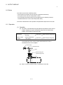
1 OVERVIEW
1. OVERVIEW
1
1.1 Overview
This programming manual describes the dedicated instructions, positioning control
parameters and positioning dedicated devices for mechanical system program
comprised of a virtual main shaft or mechanical module required to execute the
synchronous control in the Motion controller (SV22 virtual mode).
The following positioning control is possible in the Motion controller (SV22 virtual
mode).
Applicable CPU
Number of positioning control axes
Q173HCPU (32 axes)
Up to 32 axes
Q172HCPU (8 axes)
Up to 8 axes
In this manual, the following abbreviations are used.
Generic term/Abbreviation
Description
Q173HCPU/Q172HCPU or
Motion CPU (module)
Q173HCPU/Q172HCPU/Q173HCPU-T/Q172HCPU-T Motion CPU module
Q172LX/Q172EX/Q173PX or
Motion module
Q172LX Servo external signals interface module/
(Note-1)
Q172EX-S2/-S3 Serial absolute synchronous encoder interface module
/
Q173PX(-S1) Manual pulse generator interface module
MR-J3- B
Servo amplifier model MR-J3- B
AMP or Servo amplifier
General name for "Servo amplifier model MR-J3- B"
QCPU, PLC CPU or PLC CPU module
Qn(H)CPU
Multiple CPU system or Motion system
Abbreviation for "Multiple PLC system of the Q series"
CPUn
Abbreviation for "CPU No.n (n= 1 to 4) of the CPU module for the Multiple CPU
system"
Programming software package
General name for "MT Developer" and "GX Developer"
Operating system software
General name for "SW RN-SV Q "
SV13
Operating system software for conveyor assembly use (Motion SFC) :
SW6RN-SV13Q
SV22
MT Developer
GX Developer
Operating system software for automatic machinery use (Motion SFC) :
SW6RN-SV22Q
Abbreviation for Integrated start-up support software package
"MT Developer (Version 00K or later)"
Abbreviation for MELSEC PLC programming software package
"GX Developer (Version 6 or later)"
Manual pulse generator or MR-HDP01
Abbreviation for "Manual pulse generator (MR-HDP01)"
Serial absolute synchronous encoder
or Q170ENC
Abbreviation for "Serial absolute synchronous encoder (Q170ENC)"
SSCNET
(Note-2)
High speed synchronous network between Motion controller and servo
amplifier
SSCNET
High speed serial communication between Motion controller and servo
amplifier
Absolute position system
General name for "system using the servomotor and servo amplifier for
absolute position"
Battery holder unit
Battery holder unit (Q170HBATC)
(Note-2)
1-1
1 OVERVIEW
Generic term/Abbreviation
Description
External battery
General name for "Q170HBATC" and "Q6BAT"
A 0BD-PCF
A10BD-PCF/A30BD-PCF SSC I/F board
SSC I/F communication cable
Abbreviation for "Cable for SSC I/F board/card"
Intelligent function module
Abbreviation for "MELSECNET/H module/Ethernet module/
CC-Link module/Serial communication module"
(Note-1) : Q172EX can be used in SV22.
(Note-2) : SSCNET: Servo System Controller NETwork
REMARK
For information about the each module, design method for program and parameter,
refer to the following manuals relevant to each module.
Item
Reference Manual
Motion CPU module/Motion unit
Q173HCPU/Q172HCPU User’s Manual
PLC CPU, peripheral devices for PLC program design, I/O
modules and intelligent function module
Operation method for MT Developer
Manual relevant to each module
Help of each software
• Multiple CPU system configuration
• Performance specification
Q173HCPU/Q172HCPU Motion controller
• Design method for common parameter
Programming Manual (COMMON)
• Auxiliary and applied functions (common)
• Design method for Motion SFC program
SV13/SV22
• Design method for Motion SFC parameter
• Motion dedicated PLC instruction
Q173HCPU/Q172HCPU Motion controller (SV13/SV22)
Programming Manual (Motion SFC)
• Design method for positioning control
program in the real mode
Q173HCPU/Q172HCPU Motion controller (SV13/SV22)
• Design method for positioning control
Programming Manual (REAL MODE)
parameter
!
CAUTION
When designing the system, provide external protective and safety circuits to ensure safety in
the event of trouble with the Motion controller.
There are electronic components which are susceptible to the effects of static electricity
mounted on the printed circuit board. When handling printed circuit boards with bare hands you
must ground your body or the work bench.
Do not touch current-carrying or electric parts of the equipment with bare hands.
Make parameter settings within the ranges stated in this manual.
Use the program instructions that are used in programs in accordance with the conditions
stipulated in this manual.
Some devices for use in programs have fixed applications: they must be used in accordance
with the conditions stipulated in this manual.
1-2
1 OVERVIEW
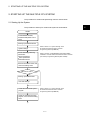
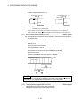
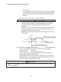
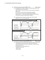
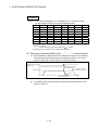
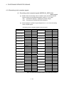
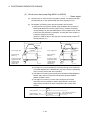
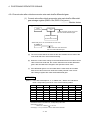
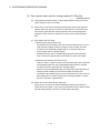
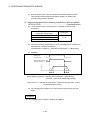
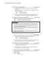
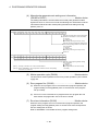
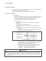
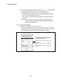
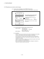
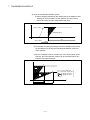
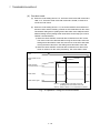
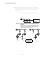
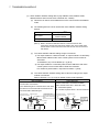
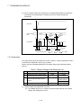
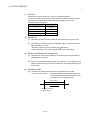
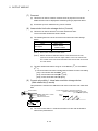
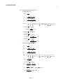
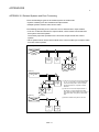
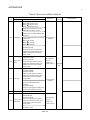
1.2 Motion Control in SV13/SV22 Real Mode
(1) System with servomotor is controlled directly using the servo program in
(SV13/SV22) real mode.
(2) Setting of the positioning parameter and creation of the servo
program/Motion SFC program are required.
(3) The procedure of positioning control is shown below:
1) Motion SFC program is requested to start using the S(P). SFCS
instruction of the PLC program.
(Motion SFC program can also be started automatically by parameter
setting.)
2) Execute the positioning control using the specified Motion SFC program.
(Output to the servo amplifier)
3) The servomotor is controlled.
Program structure in SV13/SV22 real mode
<PLC CPU>
<Motion CPU>
PLC program
Motion SFC program
1)
SP.SFCS
••••
K0
••••
••••
Transfer
[G100]
M2049//servo ON accept ?
Motion SFC
Specification of starting
program No.
program start
request instruction
2)
Servo amplifier
Servo program
[K10: real]
1 INC-2
Axis
1,
10000 PLS
Axis
2,
20000 PLS
Combined-speed 30000 PLS/s
(Note) : Motion SFC program can also be started automatically
by parameter setting.
END
Positioning control parameters
System settings
Fixed parameters
Servo parameters
Parameter blocks
Home position return data
JOG operation data
Limit switch output data
1-3
3)
Servomotor
1 OVERVIEW
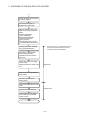
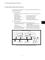
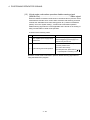
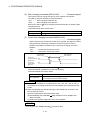
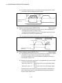
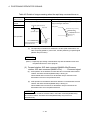
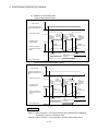
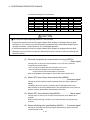
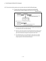
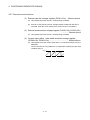
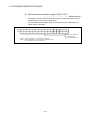
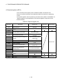
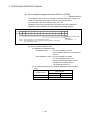
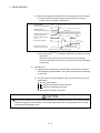
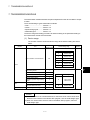
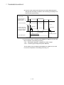
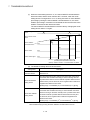
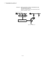
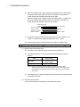
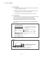
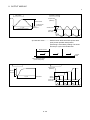
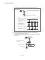
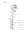
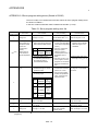
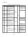
1.3 Motion Control in SV22 Virtual Mode
(1) Synchronous control with software is performed using the mechanical
system program comprised by virtual main shaft and mechanical module in
(SV22) virtual mode.
(2) Mechanical system programs is required in addition to the positioning
parameter, servo program/Motion SFC program used in real mode.
(3) The procedure of positioning control in virtual model is shown below:
1) Motion SFC program for virtual mode is requested to start using the
S(P). SFCS instruction of the PLC program.
(Motion SFC program can also be started automatically by parameter
setting.)
2) The virtual servomotor of the mechanical system program is started.
3) Output the operation result obtained through the transmission module to
the servo amplifier set as the output module.
4) The servomotor is controlled.
Program structure in SV22 virtual mode
<Motion CPU>
<PLC CPU>
PLC program
Mechanical system program
Drive module
(Virtual servomotor)
Motion SFC program
1)
SP.SFCS
••••
K0
••••
Transfer
••••
Motion SFC
Specification of starting
program No.
program start
request instruction
(Note) : Motion SFC program can also be started automatically
by parameter setting.
Transmission module
[G200]
M2044//on virtual mode?
2)
Servo program
[K100: virtual]
1 VF
Axis
1,
Speed
#
(Axis 1)
0
PLS/s
END
Output module
Positioning control parameters
System settings
Fixed parameters
Servo parameters
Parameter blocks
Limit switch output data
• Home position return data is not used, since home position return cannot be executed in virtual mode.
(Home position return is executed in real mode.)
• JOG operation in virtual mode is controlled using the JOG operation data set by drive module parameters.
3)
Servo amplifier
4)
Servomotor
1-4
3)
Servo amplifier
4)
Servomotor
2 STARTING UP THE MULTIPLE CPU SYSTEM
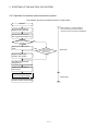
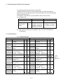
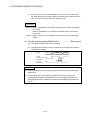
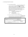
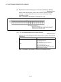
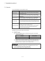
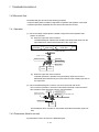
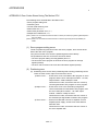
2. STARTING UP THE MULTIPLE CPU SYSTEM
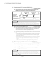
The procedure for virtual mode positioning control is shown below.
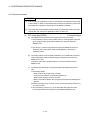
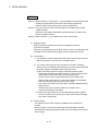
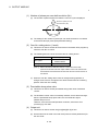
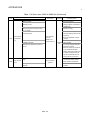
2.1 Starting Up the System
The procedure to start up for virtual mode system is shown below.
START
Install SW6RN-GSV22P,
SW3RN-CAMP(When cam is
used)
Starting up SW6RN-GSV22P
Refer to Section "3.1 System Settings" of the
Q173HCPU/Q172HCPU Motion controller
Programming Manual (COMMON).
System settings
Set the following positioning
parameters
Fixed parameters
Servo parameters
Parameter blocks
Refer to Chapter "4 PARAMETERS FOR POSITIONING
CONTROL" of the Q173HCPU/Q172HCPU Motion controller
(SV13/SV22) Programming Manual (REAL MODE).
Execute the relative check, and
correct the setting errors
Will cam be used ?
NO
YES
Starting up SW3RN-CAMP
Cam data settings
Create the mechanical system
program
Refer to Section "3.1 System Settings" of the
Q173HCPU/Q172HCPU Motion controller
Programming Manual (COMMON).
Check the mechanical system
program, and correct the setting
errors
1)
2-1
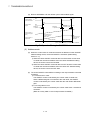
2
2 STARTING UP THE MULTIPLE CPU SYSTEM
1)
Create the Motion SFC program
and servo program
Turn the power supply of
Multiple CPU system ON
Write the following data to the
Motion CPU using a peripheral
device
System setting data
Servo setting data
Motion SFC parameter
Motion SFC program
Servo program
Mechanical system program
Cam data(When cam is used)
Refer to Section "3.1 System Settings" of the
Q173HCPU/Q172HCPU Motion controller
Programming Manual (COMMON).
Starting up the servo amplifier
using a peripheral device
Execute the JOG operation,
manual pulse generator
operation and home position
return test
Adjust cam setting axis (When
cam is used)
(Bottom dead point, stroke value,
etc.)
Real mode
Align the virtual mode operation
start position
Set data in the parameter
setting device
Switch from real mode to virtual
mode
Start drive module operation
Virtual mode
Check operation state with the
servo monitor or mechanical
system monitor
END
2-2
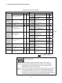
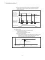
2 STARTING UP THE MULTIPLE CPU SYSTEM
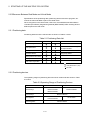
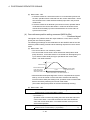
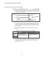
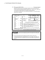
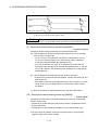
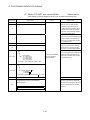
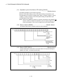
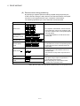
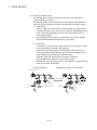
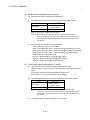
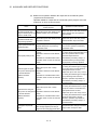
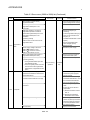
2.2 Differences Between Incremental System and Absolute System
The procedure for virtual mode operation is shown below.
2.2.1 Operation for incremental system
The operation procedure for incremental system is shown below.
START
Refer to Section "3.1 System Settings" of the
Q173HCPU/Q172HCPU Motion controller
Programming Manual (COMMON).
Turn the power supply of
Multiple CPU system ON
Execute the all axes servo
start request (Turn M2042 on)
Execute the home position
return
Align the virtual mode
operation start position
Real mode
Set data in the parameter
setting device
Switch from real mode to
virtual mode
Set the operation start address
by the current value change
Virtual mode
Execute virtual mode operation
2-3
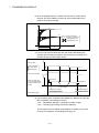
2 STARTING UP THE MULTIPLE CPU SYSTEM
2.2.2 Operation for absolute (absolute position) system
The operation procedure for absolute system is shown below.
START
Refer to Section "3.1 System Settings"
of the Q173HCPU/Q172HCPU Motion
controller Programming Manual (COMMON).
Turn the power supply of
Multiple CPU system ON
Execute the all axes servo
start request (Turn M2042 on)
Is the home
position return request
signal ON ?
YES
Execute the home position
return
Align the virtual mode
operation start position
NO
YES
Is the continuation disabled warning
signal ON ?
Real mode
NO
Set data in the parameter
setting device
Switch from real mode to
virtual mode
Set the operation start address
by the current value change
Virtual mode
Execute virtual mode operation
2-4
2 STARTING UP THE MULTIPLE CPU SYSTEM
2.3 Differences Between Real Mode and Virtual Mode
Specifications of the positioning data, positioning devices and servo programs, etc.
used in the real mode differ in part in the virtual mode.
When using them in the virtual mode, refer to the "Q173HCPU/Q172HCPU Motion
controller (SV13/SV22) Programming Manual (REAL MODE)" after checking about a
different point in the real mode.
2.3.1 Positioning data
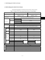
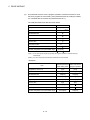
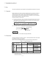
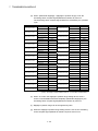
Positioning data used in the virtual mode are shown in Table 2.1 below.
Table 2.1 Positioning Data List
Item
Real mode
Virtual mode
Remark
System settings
Usable units differ according to
Fixed parameters
the output module.
Servo parameters
Parameter blocks
Only [PLS] usable.
Home position return data
JOG operation data
Limit switch output data
: Used
: Used (Restrictions in part)
: Not used
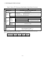
2.3.2 Positioning devices
The operating ranges of positioning devices used in virtual mode are shown in Table
2.2 below.
Table 2.2 Operating Range of Positioning Devices
Device name
Real mode
Virtual mode
M2000 to M3839
Internal relays
M4640 to M4687
M2000 to M5599
M5440 to M5487
Special relays
M9073 to M9079
D0 to D799
Data registers
D1120 to D1239
Special registers
D9180 to D9201
2-5
D0 to D1559
2 STARTING UP THE MULTIPLE CPU SYSTEM
2.3.3 Servo programs
(1) Servo program area
(a) The same servo program (Kn) No. cannot be used in both the real and virtual
modes. The range of the servo program (Kn) used in the virtual mode must
be set in advance.
(The range is set using a peripheral device which started SW6RN-GSV22P.)
(2) Servo instructions
(a) The home position return, speed control ( ), speed/position switching control,
high-speed oscillation control and speed control with fixed position stop
among the controls which can be used in the real mode cannot be used in
the virtual mode.
(b) Control units of the parameter block and the torque limit value among the
positioning data which can be set using the servo program are not used.
(3) Differences of the servo instruction between real mode and virtual mode are
shown in Table 2.3 below.
Table 2.3 Differences of Servo Instruction List
Item
Real
Virtual
mode
mode
Remark
VPF
Speed/position
control
VPR
VPSTART
VVF
Speed control ( )
Servo
instruction
VVR
Home position
return
Switch to virtual
mode after home
position return in the
real mode.
ZERO
High-speed
oscillation
OSC
Speed control
with fixed position
stop
PVF
PVR
Fixed
as
"PLS"
Control units
Positioning
data
Parameter block
The torque limit
value is set with the
"drive module
parameter".
Torque limit value
: Used,
: Unusable,
: Not used
(Note) : It is common in the real mode and virtual mode about instructions except for the above
table.
2-6
2 STARTING UP THE MULTIPLE CPU SYSTEM
2.3.4 Control change (Current value change/speed change)
When a control change is executed in the virtual mode, the feed current value/speed of
the drive module is changed.
Control changes are not possible for the output module (except for cam).
Differences between control changes in the real and virtual modes are shown in Table
2.4 below.
Table 2.4 Differences List of Control Change
Virtual mode
Item
Real
mode
Drive module
Virtual
Synchronous
servomotor
encoder
Output module
Roller
Ball
Rotary
screw
table
Cam
Current value
change
(Note-1)
Speed change
: Used,
: Unusable
(Note-1) : If the output module is a roller which uses a speed change gear, a speed change can
be executed by changing the speed change gear ratio.
REMARK
1) Refer to the following Chapters for details of the drive and output modules.
• Drive module : Chapter 5 and 6
• Output module : Chapter 5 and 8
2-7
2 STARTING UP THE MULTIPLE CPU SYSTEM
MEMO
2-8
3 PERFORMANCE SPECIFICATIONS
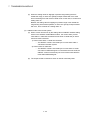
3. PERFORMANCE SPECIFICATIONS
Performance specifications of the Motion CPU are shown in Table 3.1 below.
Table 3.1 Motion CPU Performance Specifications (Virtual Mode)
Item
Number of control axes
Q173HCPU(-T)
Q172HCPU(-T)
Up to 32 axes
(Simultaneous : 2 to 4 axes)
(Independent : 32 axes)
Up to 8 axes
(Simultaneous : 2 to 4 axes)
(Independent : 8 axes)
Synchronous control, PTP (Point to Point), speed control, fixed-pitch feed, constant-speed control,
position follow-up control, speed-switching control
Control method
Drive module
Virtual servomotor
PLS
Synchronous encoder
Roller
Control units
Output module
mm, inch
Ball screw
Rotary table
Fixed as "degree"
Cam
mm, inch, PLS
Program language
Dedicated instructions (Servo program + mechanical system program)
14k steps (14334 steps)
Capacity
Servo program
Number of
positioning points
(Note-2)
Total of 3200 points (It changes with programs, indirect specification is possible.)
Number of modules which can be set per CPU
Mechanical system program
Drive
modules
Virtual
axes
Transmission
modules
Output
modules
Virtual module
32 axes
8 axes
Synchronous
encoder
12 axes
8 axes
Main shaft
32
8
Auxiliary input
axis
32
8
Gear
64
16
Clutch
64
16
Speed change
gear
64
16
Differential gear
32
8
Differential gear
to main shaft
32
8
Roller
32
8
Ball screw
32
8
Rotary table
32
Cam
Program setting method
Total of 32
32
WindowsNT
R
4.0/ Windows
98/ Windows
R
2000/ Windows
Up to 256
Memory capacity
R
XP which started SW6RN-GSV22P
(Note-3)
256 • 512 • 1024 • 2048
Resolution per cycle
Cam
Total of 8
8
R
Types
(Note-3)
132k bytes
Storage memory for cam data
CPU internal RAM memory
Stroke resolution
32767
Control mode
Cam data setting method
8
Two-way cam/feed cam
WindowsNT
R
4.0/ Windows
R
98/ Windows
3-1
R
2000/ Windows
R
XP which started SW3RN-CAMP
3
3 PERFORMANCE SPECIFICATIONS
Table 3.1 Motion CPU Performance Specifications (Virtual Mode) (Continued)
Item
Q173HCPU(-T)
Interpolation functions
Linear interpolation (2 to 4 axes), circular interpolation (2 axes)
PTP (Point to Point), speed control, fixed-pitch feed, constant-speed control,
position follow-up control
Control methods
PTP
: Selection of absolute or incremental data method
Fixed-pitch feed
: Incremental data method
Constant-speed control : Both absolute and incremental data method can be used together
Position follow-up control : Absolute data method
Method
Positioning
Position command
Address setting range : –2147483648 to 2147483647 [PLS]
Virtual servomotor
Speed command
Acceleration/
deceleration
control
Q172HCPU(-T)
Speed setting range : 1 to 2147483647 [PLS/s]
Automatic
trapezoidal
acceleration/
deceleration
Acceleration-fixed acceleration/deceleration
Time-fixed acceleration/deceleration
Acceleration time : 1 to 65535 [ms]
Acceleration/deceleration time:1 to 5000 [ms]
(Only constant-speed control is possible.)
Deceleration time : 1 to 65535 [ms]
S-curve
acceleration/
deceleration
S-curve ratio : 0 to 100[%]
JOG operation function
Provided
M-function (with mode)
M-code output function provided, M-code complete wait function provided
Up to 3 units can be connected.
Up to 3 axes can be operated simultaneously.
Setting of magnification : 1 to 10000
Setting of smoothing magnification provided.
Manual pulse generator operation
function
(Test mode only)
(Note-1) : When the TREN input signal is used as "external input mode clutch", the high speed reading function cannot be used.
(Note-2) : Capacity matching the servo program for real mode.
(Note-3) : Relation between a resolution per cycle of cam and type are shown below.
Resolution per cycle
256
512
1024
2048
Type
256
128
64
32
3-2
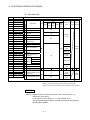
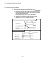
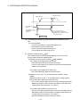
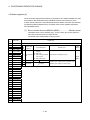
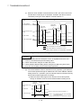
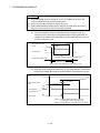
4 POSITIONING DEDICATED SIGNALS
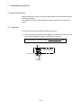
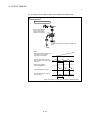
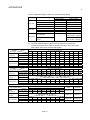
4. POSITIONING DEDICATED SIGNALS
The internal signals of the Motion CPU and the external signals to the Motion CPU are
used as positioning signals.
(1) Internal signals
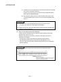
The following five devices of the Motion CPU are used as the internal signals of
the Motion CPU.
• Internal relay (M) .............................. M2000 to M5599 (3600 points)
• Special relay (SP.M) ........................ M9073 to M9079 (7 points)
• Data register (D) .............................. D0 to D1599 (1600 points)
• Motion register (#) ........................... #8000 to #8191 (192 points)
• Special register (SP.D) .................... D9112, D9180 to D9201 (23 points)
(2) External signals
The external input signals to the Motion CPU are shown below.
• Upper/lower limit switch input .......... The upper/lower limit of the positioning
range is controlled.
• Stop signal ....................................... This signal makes the starting axis stop.
• Proximity dog signal......................... ON/OFF signal from the proximity dog.
• Speed/position switching signal ...... Signal for switching from speed to position.
• Manual pulse generator input .......... Signal from the manual pulse generator.
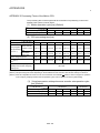
Configuration between modules
PLC CPU
Motion CPU
1)
2)
Device memory
Device memory
Motion control
processor
PLC control
processor
Shared CPU
memory
Shared CPU
memory
SSCNET
PLC bus
Servo amplifier
Sensor, solenoid, etc. PLC intelligent function
module (A/D, D/A, etc.)
(DI/O)
Motion control dedicated I/F
(DOG signal, manual
pulse generator)
M
M
Servomotor
Note) : Device memory data : 1) = 2)
Fig.4.1 Flow of the internal signals/external signals
4-1
4
4 POSITIONING DEDICATED SIGNALS
The positioning dedicated devices are shown below.
It indicates the device refresh cycle of the Motion CPU for status signal with the
positioning control, and the device fetch cycle of the Motion CPU for command signal
with the positioning control.
The operation cycle and main cycle of the Motion CPU are shown below.
(a) Operation cycle
Item
Q173HCPU
Q172HCPU
Up to 32 axes
Up to 8 axes
0.88[ms] / 1 to 5 axes
1.77[ms] / 6 to 14 axes
3.55[ms] / 15 to 28 axes
7.11[ms] / 29 to 32 axes
0.88[ms] / 1 to 5 axes
1.77[ms] / 6 to 8 axes
Number of control axes
Operation cycle
(Default)
SV22
(b) Main cycle is not fixed-cycle as operation cycle. The cycle is dozens[ms] to
hundreds[ms].
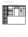
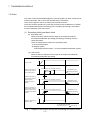
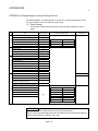
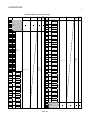
4.1 Internal Relays
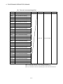
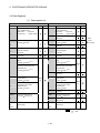
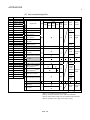
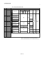
(1) Internal relay list
Q173HCPU
Device No.
M0
to
M2000
Purpose
User device
(2000 points)
Q172HCPU
Real
Virtual
Device No.
M0
to
Purpose
M2000
M2320
to
Special relay allocated device
(Status)
(80 points)
M2320
M2400
Axis status
(20 points 32 axes)
Real mode …... Each axis
Virtual mode … Output module
M2400
Unusable
(32 points)
M2560
Common device
(Command signal)
(64 points)
M3072
Special relay allocated device
(Command signal)
(64 points)
M3136
Axis command signal
(20 points 32 axes)
Real mode …... Each axis
Virtual mode … Output module
M3200
Axis command signal
(20 points 8 axes)
to
Real mode …... Each axis
Virtual mode … Output module
to
M3040
to
M3072
to
M3136
to
M3200
to
M3840
to
M3999
Unusable
(160 points)
to
to
to
to
to
to
M3360
to
M3999
4-2
Virtual
User device
(2000 points)
Common device
(320 points)
to
Real
Common device
(320 points)
Special relay allocated device
(Status)
(80 points)
Axis status
(20 points 8 axes)
Real mode …... Each axis
Virtual mode … Output module
Unusable
(512 points)
Common device
(Command signal)
(64 points)
Special relay allocated device
(Command signal)
(64 points)
Unusable
(640 points)
Real/
virtual
community
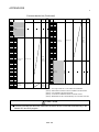
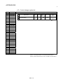
4 POSITIONING DEDICATED SIGNALS
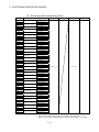
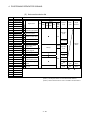
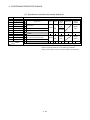
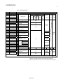
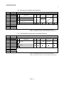
Internal relay list (Continued)
Q173HCPU
Device No.
Purpose
M4000 (Note-1) Virtual servomotor axis status
(20 points 32 axes) (Note-2)
to
Q172HCPU
Real
Back
up
Virtual
Device No.
Purpose
M4000 (Note-1) Virtual servomotor axis status
(20 points 8 axes) (Note-2)
to
Real
Virtual
Back
up
M4160 (Note-1) Unusable
(480 points)
to
M4640 (Note-1) Synchronous encoder axis
status
to
(4 points 12 axes)
M4640 (Note-1) Synchronous encoder axis
status
to
(4 points 8 axes)
M4688 (Note-1) Unusable
(112 points)
to
M4672 (Note-1) Unusable
(128 points)
to
M4800 (Note-1) Virtual servomotor axis
command signal
to
(20 points 32 axes) (Note-2)
M4800 (Note-1) Virtual servomotor axis
command signal
to
(20 points 8 axes) (Note-2)
M4960 (Note-1) Unusable
(480 points)
to
M5440 (Note-1) Synchronous encoder axis
command signal
to
(4 points 12 axes)
M5440 (Note-1) Synchronous encoder axis
command signal
to
(4 points 8 axes)
Virtual
M5472 (Note-1) Unusable
(16 points)
to
M5488 (Note-1) Cam axis command signal
(1 point 32 axes) (Note-3)
to
M5488 (Note-1) Cam axis command signal
(1 point 8 axes) (Note-3)
to
M5496
to
Unusable
(24 points)
M5520
to
Smoothing clutch complete
signal
(2 points 32 axes) (Note-2)
M5520
to
Smoothing clutch complete
signal
(2 points 8 axes) (Note-2)
M5584
to
Unusable
(16 points)
M5536
to
Unusable
(64 points)
M5600
User device
(2592 points)
M5600
to
User device
(2592 points)
to
M8191
M8191
: Valid,
: Invalid
It can be used as an user device.
POINT
• Total number of user device points
4592 points
(Note-1) : Do not set M4000 to M5599 as the latch range in virtual mode.
(Note-2) : This signal occupies only the area of the axis set in the mechanical
system program. The unused axis areas in the mechanical system
program can be used as an user device.
(Note-3) : Unused axis of cam axis command signal can be used as an user device.
(Note-4) : As for "axis status (M2400 to)" and "axis command signal (M3200 to)",
only details for internal relays used in the virtual mode are described in
this manual. If it is required, refer to the "Q173HCPU/Q172HCPU Motion
controller (SV13/SV22) Programming Manual (REAL MODE)".
4-3
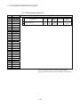
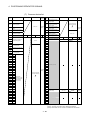
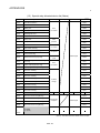
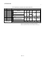
4 POSITIONING DEDICATED SIGNALS
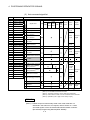
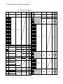
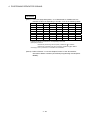
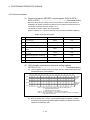
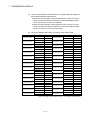
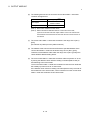
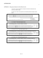
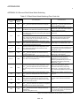
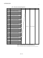
(2) Axis status list
Axis No.
Device No.
1
M2400 to M2419
Signal name
2
M2420 to M2439
3
M2440 to M2459
4
M2460 to M2479
5
M2480 to M2499
6
M2500 to M2519
0 Positioning start complete
7
M2520 to M2539
1 Positioning complete
8
M2540 to M2559
9
M2560 to M2579
10
M2580 to M2599
3 Command in-position
11
M2600 to M2619
4 Speed controlling
12
M2620 to M2639
13
M2640 to M2659
Virtual
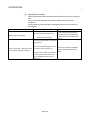
Signal name
Real
Real
Ball Rotary
Cam Mode
Roller
screw table
axis
Refresh
cycle
Fetch Signal
cycle direction
OFF
2 In-position
5
Operation
cycle
OFF
Speed / position
switching latch
14
M2660 to M2679
6 Zero pass
15
M2680 to M2699
7 Error detection
16
M2700 to M2719
17
M2720 to M2739
18
M2740 to M2759
19
M2760 to M2779
20
M2780 to M2799
21
M2800 to M2819
22
M2820 to M2839
11
23
M2840 to M2859
24
M2860 to M2879
12 External RLS
13 signals STOP
Immediately
8 Servo error detection
Operation
cycle
9
Home position return
request
Main cycle
10
Home position return
complete
Operation
cycle
Status
signal
FLS
Main cycle
DOG/CHANGE
25
M2880 to M2899
14
26
M2900 to M2919
15 Servo ready
27
M2920 to M2939
16 Torque limiting
28
M2940 to M2959
17 Unusable
29
M2960 to M2979
30
M2980 to M2999
31
M3000 to M3019
Virtual mode continuation
18 operation disable warning
(Note-1)
signal
32
M3020 to M3039
Operation
cycle
At virtual
mode
transition
OFF
19 M-code outputting signal
Operation
cycle
Status
signal
: Valid
(Note-1) : It is unusable in the SV22 real mode.
(Note-2) : The range of axis No.1 to 8 is valid in the Q172HCPU.
(Note-3) : Device area of 9 axes or more is unusable in the Q172HCPU.
REMARK
(Note-1) : Details except for internal relays used in the virtual mode are not
described in this manual.
If it is required, refer to Section "3.1.1 Axis statuses" of the
"Q173HCPU/Q172HCPU Motion controller (SV13/SV22) Programming
Manual (REAL MODE)".
4-4
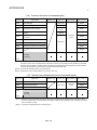
4 POSITIONING DEDICATED SIGNALS
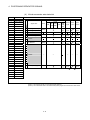
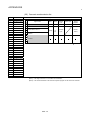
(3) Axis command signal list
Axis No.
Device No.
1
M3200 to M3219
2
M3220 to M3239
3
M3240 to M3259
4
M3260 to M3279
5
M3280 to M3299
Signal name
Virtual
Signal name
6
M3300 to M3319
0 Stop command
7
M3320 to M3339
1 Rapid stop command
8
M3340 to M3359
9
M3360 to M3379
10
M3380 to M3399
11
M3400 to M3419
12
M3420 to M3439
13
M3440 to M3459
14
M3460 to M3479
15
M3480 to M3499
16
M3500 to M3519
6 Unusable
17
M3520 to M3539
7 Error reset command
18
M3540 to M3559
19
M3560 to M3579
20
M3580 to M3599
21
M3600 to M3619
22
M3620 to M3639
10
23
M3640 to M3659
11
24
M3660 to M3679
25
M3680 to M3699
26
M3700 to M3719
27
M3720 to M3739
28
M3740 to M3759
29
M3760 to M3779
30
M3780 to M3799
31
M3800 to M3819
32
M3820 to M3839
2
Forward rotation JOG
start command
3
Reverse rotation JOG
start command
4
Complete signal OFF
command
5
Speed/position switching
enable command
8
Servo error reset
command
9
External stop input
disable at start command
Real
Roller
Real Refresh
Ball Rotary
Cam mode cycle
screw table
axis
Fetch
cycle
Signal
direction
Operation
cycle
Main
cycle
Command
signal
Operation
cycle
Main
cycle
Command
signal
At start
Unusable
12
Feed current value
update request command
13
Address clutch reference
(Note-1)
setting command
14
Cam reference position
(Note-1)
setting command
At start
At virtual
mode
transition Command
signal
Operation
cycle
15 Servo OFF command
Operation
cycle
16 Gain changing command
(Note-4)
17 Unusable
18
Control loop changing
command
Operation Command
cycle
signal
19 FIN signal
: Valid,
: Invalid
(Note-1) : It is unusable in the SV22 real mode.
(Note-2) : The range of axis No.1 to 8 is valid in the Q172HCPU.
(Note-3) : Device area of 9 axes or more is unusable in the Q172HCPU.
(Note-4) : Operation cycle 7.1[ms] or more: Every 3.5[ms]
REMARK
(Note-1) : Details except for internal relays used in the virtual mode are not
described in this manual. If it is required, refer to Section "3.1.2 Axis
command signals" of the "Q173HCPU/Q172HCPU Motion controller
(SV13/SV22) Programming Manual (REAL MODE)".
4-5
4 POSITIONING DEDICATED SIGNALS
(4) Virtual servomotor axis status list
Axis No.
Device No.
1
M4000 to M4019
Signal name
2
M4020 to M4039
3
M4040 to M4059
4
M4060 to M4079
5
M4080 to M4099
6
M4100 to M4119
0 Positioning start complete
7
M4120 to M4139
1 Positioning complete
8
M4140 to M4159
2 Unusable
9
M4160 to M4179
3 Command in-position
10
M4180 to M4199
4 Speed controlling
11
M4200 to M4219
5
12
M4220 to M4239
6
13
M4240 to M4259
14
M4260 to M4279
15
M4280 to M4299
8
16
M4300 to M4319
9
17
M4320 to M4339
10
18
M4340 to M4359
11
19
M4360 to M4379
12
20
M4380 to M4399
13 Unusable
21
M4400 to M4419
14
22
M4420 to M4439
15
23
M4440 to M4459
16
24
M4460 to M4479
17
25
M4480 to M4499
18
26
M4500 to M4519
27
M4520 to M4539
28
M4540 to M4559
29
M4560 to M4579
30
M4580 to M4599
31
M4600 to M4619
32
M4620 to M4639
Virtual
Signal name
Real
Real Refresh
Ball Rotary
cycle
Cam mode
Roller
screw table
axis
Fetch Signal
cycle direction
Backup
Operation
cycle
Status
signal
Backup
Operation
cycle
Status
signal
Backup
Immediately
Status
signal
Unusable
7 Error detection
19 M-code outputting signal
—
Backup
—
—
—
Operation
cycle
: Valid,
—
Status
signal
: Invalid
(Note-1) : The range of axis No.1 to 8 is valid in the Q172HCPU.
(Note-2) : The unused axis areas in the mechanical system program can be used as an user device.
4-6
4 POSITIONING DEDICATED SIGNALS
(5) Virtual servomotor axis command signal list
Axis No.
Device No.
1
M4800 to M4819
2
M4820 to M4839
3
M4840 to M4859
4
M4860 to M4879
5
M4880 to M4899
Signal name
Virtual
Signal name
6
M4900 to M4919
0 Stop command
7
M4920 to M4939
1 Rapid stop command
8
M4940 to M4959
9
M4960 to M4979
10
M4980 to M4999
11
M5000 to M5019
12
M5020 to M5039
13
M5040 to M5059
14
M5060 to M5079
5
15
M5080 to M5099
6
16
M5100 to M5119
17
M5120 to M5139
18
M5140 to M5159
8 Unusable
19
M5160 to M5179
20
M5180 to M5199
21
M5200 to M5219
External stop input
9 disable at start
command
22
M5220 to M5239
10
23
M5240 to M5259
11
24
M5260 to M5279
12
25
M5280 to M5299
13
26
M5300 to M5319
14 Unusable
27
M5320 to M5339
15
28
M5340 to M5359
16
29
M5360 to M5379
17
30
M5380 to M5399
18
31
M5400 to M5419
32
M5420 to M5439
2
Forward rotation JOG
start command
3
Reverse rotation JOG
start command
4
Complete signal OFF
command
Real
Roller
Real Refresh
Ball Rotary
Cam mode cycle
screw table
axis
Fetch
cycle
Signal
direction
Operation
cycle
Main
cycle
Unusable
7 Error reset command
Main
cycle
Command
signal
At start
Command
signal
Operation Command
cycle
signal
19 FIN signal
: Valid,
: Invalid
(Note-1) : The range of axis No.1 to 8 is valid in the Q172HCPU.
(Note-2) : The unused axis areas in the mechanical system program can be used as an user device.
4-7
4 POSITIONING DEDICATED SIGNALS
(6) Synchronous encoder axis status list
Axis No.
Device No.
1
M4640 to M4643
Signal name
2
M4644 to M4647
3
M4648 to M4651
4
M4652 to M4655
0 Error detection
5
M4656 to M4659
1 External signal TREN
6
M4660 to M4663
7
M4664 to M4667
Virtual mode continuation operation
2
disable warning
8
M4668 to M4671
3 Unusable
9
M4672 to M4675
10
M4676 to M4679
11
M4680 to M4683
12
M4684 to M4687
Signal name
Real
Virtual Refresh cycle
Fetch cycle
Signal
direction
Immediately
Status
signal
Main cycle
: Valid
(Note-1) : The range of axis No.1 to 8 is valid in the Q172HCPU.
(Note-2) : Device area of 9 axes or more is unusable in the Q172HCPU.
(7) Synchronous encoder axis command signal list
Axis No.
Device No.
1
M5440 to M5443
Signal name
2
M5444 to M5447
3
M5448 to M5451
4
M5452 to M5455
5
M5456 to M5459
6
M5460 to M5463
7
M5464 to M5467
2 Unusable
8
M5468 to M5471
3
9
M5472 to M5475
10
M5476 to M5479
11
M5480 to M5483
12
M5484 to M5487
Signal name
Real
0 Error reset
Virtual Refresh cycle
Fetch cycle
Signal
direction
Main cycle
Status
signal
1
: Valid,
: Invalid
(Note-1) : The range of axis No.1 to 8 is valid in the Q172HCPU.
(Note-2) : Device area of 9 axes or more is unusable in the Q172HCPU.
4-8
4 POSITIONING DEDICATED SIGNALS
(8) Cam axis command signal list
Device No.
Signal name
Refresh cycle
M5488
Axis-1 cam/ball screw switching
M5489
Axis-2 cam/ball screw switching
M5490
Axis-3 cam/ball screw switching
M5491
Axis-4 cam/ball screw switching
M5492
Axis-5 cam/ball screw switching
M5493
Axis-6 cam/ball screw switching
M5494
Axis-7 cam/ball screw switching
M5495
Axis-8 cam/ball screw switching
M5496
Axis-9 cam/ball screw switching
M5497
Axis-10 cam/ball screw switching
M5498
Axis-11 cam/ball screw switching
M5499
Axis-12 cam/ball screw switching
M5500
Axis-13 cam/ball screw switching
M5501
Axis-14 cam/ball screw switching
M5502
Axis-15 cam/ball screw switching
M5503
Axis-16 cam/ball screw switching
M5504
Axis-17 cam/ball screw switching
M5505
Axis-18 cam/ball screw switching
M5506
Axis-19 cam/ball screw switching
M5507
Axis-20 cam/ball screw switching
M5508
Axis-21 cam/ball screw switching
M5509
Axis-22 cam/ball screw switching
M5510
Axis-23 cam/ball screw switching
M5511
Axis-24 cam/ball screw switching
M5512
Axis-25 cam/ball screw switching
M5513
Axis-26 cam/ball screw switching
M5514
Axis-27 cam/ball screw switching
M5515
Axis-28 cam/ball screw switching
M5516
Axis-29 cam/ball screw switching
M5517
Axis-30 cam/ball screw switching
M5518
Axis-31 cam/ball screw switching
M5519
Axis-32 cam/ball screw switching
Fetch cycle
Signal direction
Main cycle
Command signal
Remark
(Note-1) : The range of axis No.1 to 8 is valid in the Q172HCPU.
(Note-2) : Device area of 9 axes or more is unusable in the Q172HCPU.
(Note-3) : Unused axis of cam axis command signal can be used as an user device.
4-9
4 POSITIONING DEDICATED SIGNALS
(9) Smoothing clutch complete signal list
Device No.
M5520
M5521
M5522
M5523
M5524
M5525
M5526
M5527
M5528
M5529
M5530
M5531
M5532
M5533
M5534
M5535
M5536
M5537
M5538
M5539
M5540
M5541
M5542
M5543
M5544
M5545
M5546
M5547
M5548
M5549
M5550
M5551
M5552
M5553
M5554
M5555
M5556
M5557
M5558
M5559
M5560
M5561
M5562
M5563
M5564
M5565
M5566
M5567
M5568
M5569
M5570
M5571
M5572
M5573
M5574
M5575
M5576
M5577
M5578
M5579
M5580
M5581
M5582
M5583
Signal name
Output axis 1
Output axis 2
Output axis 3
Output axis 4
Output axis 5
Output axis 6
Output axis 7
Output axis 8
Output axis 9
Output axis 10
Output axis 11
Output axis 12
Output axis 13
Output axis 14
Output axis 15
Output axis 16
Output axis 17
Output axis 18
Output axis 19
Output axis 20
Output axis 21
Output axis 22
Output axis 23
Output axis 24
Output axis 25
Output axis 26
Output axis 27
Output axis 28
Output axis 29
Output axis 30
Output axis 31
Output axis 32
Refresh cycle
Fetch cycle
Signal direction
Remark
Main shaft side
Auxiliary input side
Main shaft side
Auxiliary input side
Main shaft side
Auxiliary input side
Main shaft side
Auxiliary input side
Main shaft side
Auxiliary input side
Main shaft side
Auxiliary input side
Main shaft side
Auxiliary input side
Main shaft side
Auxiliary input side
Main shaft side
Auxiliary input side
Main shaft side
Auxiliary input side
Main shaft side
Auxiliary input side
Main shaft side
Auxiliary input side
Main shaft side
Auxiliary input side
Main shaft side
Auxiliary input side
Main shaft side
Auxiliary input side
Main shaft side
Auxiliary input side
Main shaft side
Operation cycle
Status signal
Auxiliary input side
Main shaft side
Auxiliary input side
Main shaft side
Auxiliary input side
Main shaft side
Auxiliary input side
Main shaft side
Auxiliary input side
Main shaft side
Auxiliary input side
Main shaft side
Auxiliary input side
Main shaft side
Auxiliary input side
Main shaft side
Auxiliary input side
Main shaft side
Auxiliary input side
Main shaft side
Auxiliary input side
Main shaft side
Auxiliary input side
Main shaft side
Auxiliary input side
Main shaft side
Auxiliary input side
Main shaft side
Auxiliary input side
Main shaft side
Auxiliary input side
(Note-1) : The range of axis No.1 to 8 is valid in the Q172HCPU.
(Note-2) : Device area of 9 axes or more is unusable in the Q172HCPU.
(Note-3) : Unused axis of mechanical system program can be used as an user device.
4 - 10
4 POSITIONING DEDICATED SIGNALS
(10) Common device list
Device
Signal name
No.
Refresh cycle
Fetch cycle
Signal
Remark
Device
direction
(Note-5)
No.
M3072
M2053
Command
M2000 PLC ready flag
Main cycle
signal
(Note-4)
M2001 Axis 1
Signal name
M2055
M2004 Axis 4
M2056
M2005 Axis 5
M2057 Unusable
M2006 Axis 6
M2058 (6 points)
M2007 Axis 7
M2059
M2008 Axis 8
M2060
M2009 Axis 9
M2061 Axis 1
M2010 Axis 10
M2062 Axis 2
M2011 Axis 11
M2063 Axis 3
M2012 Axis 12
M2064 Axis 4
M2013 Axis 13
M2065 Axis 5
M2014 Axis 14
M2016 Axis 16
M2017 Axis 17
M2071 Axis 11
M2020 Axis 20
M2072 Axis 12
M2021 Axis 21
M2073 Axis 13
M2022 Axis 22
M2074 Axis 14
M2023 Axis 23
M2075 Axis 15
M2024 Axis 24
M2076 Axis 16
M2025 Axis 25
M2077 Axis 17
M2026 Axis 26
M2078 Axis 18
M2027 Axis 27
M2079 Axis 19
M2028 Axis 28
M2080 Axis 20
M2029 Axis 29
M2081 Axis 21
M2030 Axis 30
M2082 Axis 22
M2031 Axis 31
M2083 Axis 23
M2032 Axis 32
M2084 Axis 24
M2033 Unusable
M2035
M2036
M2037
M2038
M2039
M2040
Personal computer link
communication error flag
Main cycle
clear request flag (Note-6)
M2044
M2045
Status
M2086 Axis 26
signal
M2087 Axis 27
Command
signal
M3080
Immediate
flag
At start
flag
signal
M2094
signal
M2095
M3073
(Note-4)
request (SV22)
M2098
signal
Operation cycle
Command
At virtual mode
signal
transition
(Note-4)
M2099
M3074
M3075
M2051
status (SV22)
M2052
M2105 Axis 5
transition
Status
M2106 Axis 6
signal
M2107 Axis 7
M2108 Axis 8
Main cycle
signal
value changing flag
(Note-3)
(12 axes)
M2111 Axis 11
M3076
(Note-4)
Operation cycle
Main cycle
M2112 Axis 12
M2113
Status
M2114
signal
M2115 Unusable
Command
M3077
signal
(Note-4)
M3078
M2116 (6 points)
M2117
M2118
4 - 11
Status
encoder current
M2110 Axis 10
Command
Manual pulse generator 1
enable flag
Synchronous
M2109 Axis 9
Operation cycle
start command
Manual pulse generator 2
M2102 Axis 2
M2104 Axis 4
At virtual mode
JOG operation simultaneous
enable flag
M2100
M2101 Axis 1
M2103 Axis 3
Real/virtual mode switching
M2050 Start buffer full
M2096 Unusable
M2097 (8 points)
Status
Operation cycle
Real/virtual mode switching
M2049 All axes servo ON accept flag
M2088 Axis 28
M2093
M2046 Out-of-sync warning (SV22)
M2048
(Note-2)
M2089 Axis 29
Status
Command
Speed switching point specified
M2047 Motion slot fault detection flag
signal
(Note-1),
M2092 Axis 32
Motion SFC error detection
error detection (SV22)
Operation cycle
M2091 Axis 31
(3 points)
Real/virtual mode switching
Status
Speed changing flag
M2090 Axis 30
Unusable
M2042 All axes servo ON command
M2043
signal
M2085 Axis 25
Operation cycle
Motion SFC error history
M2041 System setting error flag
Status
M2070 Axis 10
M2019 Axis 19
M2034
Operation cycle
M2069 Axis 9
(Note-2)
M2018 Axis 18
signal
(Note-4)
M2068 Axis 8
(Note-1),
Operation cycle
Remark
(Note-5)
M2067 Axis 7
signal
Start accept flag
Signal
direction
M2066 Axis 6
Status
M2015 Axis 15
Main cycle
enable flag
M2003 Axis 3
Fetch cycle
Command
Manual pulse generator 3
M2054 Operation cycle over flag
M2002 Axis 2
Refresh cycle
Operation cycle
signal
(Note-1),
(Note-2)
M3079
4 POSITIONING DEDICATED SIGNALS
Common device list (Continued)
Refresh cycle
Fetch cycle
Signal
Remark
Device
direction
(Note-5)
No.
M2119
M2180
M2120
M2123
M2124
M2182
Unusable
(9 points)
M2184
M2126
M2128 Axis 1
M2186
M2129 Axis 2
M2131 Axis 4
M2188
M2132 Axis 5
M2134 Axis 7
M2190
M2135 Axis 8
M2137 Axis 10
M2192
M2138 Axis 11
M2140 Axis 13
M2194
M2141 Axis 14
M2143 Axis 16
Automatic
M2144 Axis 17
deceleration flag
M2196
M2146 Axis 19
M2198
M2147 Axis 20
M2149 Axis 22
M2200
M2150 Axis 23
M2152 Axis 25
M2202
M2153 Axis 26
M2155 Axis 28
M2204
M2156 Axis 29
M2157 Axis 30
Status
M2158 Axis 31
Operation cycle
M2159 Axis 32
Output
M2169 axis 5
M2170
Output
M2171 axis 6
M2172
Output
M2173 axis 7
M2174
Output
M2175 axis 8
M2176
Output
M2177 axis 9
M2178
Output
M2179 axis 10
Auxiliary input
side
Auxiliary input
Auxiliary input
M2212
side
Auxiliary input
Main shaft side
Auxiliary input
side
Main shaft side
Auxiliary input
side
Main shaft side
Auxiliary input
side
Main shaft side
Auxiliary input
Output
Output
M2213 axis 27
Main shaft side
side
Output
M2211 axis 26
Main shaft side
Auxiliary input
Output
M2207 axis 24
M2210
side
Main shaft side
M2206
M2209 axis 25
Main shaft side
side
(Note-1),
Output
M2205 axis 23
M2208
M2214
(Note-3)
M2168
signal
(Note-2)
Main shaft side
Clutch status (SV22)
M2167 axis 4
Output
M2203 axis 22
M2154 Axis 27
Output
Output
M2201 axis 21
M2151 Axis 24
M2166
Output
M2199 axis 20
M2148 Axis 21
M2165 axis 3
Output
M2197 axis 19
M2145 Axis 18
Output
Output
M2195 axis 18
M2142 Axis 15
M2163 axis 2
Output
M2193 axis 17
M2139 Axis 12
Output
Output
M2191 axis 16
M2136 Axis 9
M2161 axis 1
Output
M2189 axis 15
M2133 Axis 6
Output
Output
M2187 axis 14
M2130 Axis 3
M2164
Output
M2185 axis 13
M2127
M2162
Output
M2183 axis 12
M2125
M2160
Output
M2181 axis 11
M2121
M2122
Signal name
Output
M2215 axis 28
M2216
Output
M2217 axis 29
M2218
Output
M2219 axis 30
M2220
Output
M2221 axis 31
M2222
Output
M2223 axis 32
M2225
Main shaft side
M2226
Auxiliary input
M2227
side
M2228
4 - 12
Fetch cycle
Signal
Remark
direction
(Note-5)
Main shaft side
Auxiliary input
side
Main shaft side
Auxiliary input
side
Main shaft side
Auxiliary input
side
Main shaft side
Auxiliary input
side
Main shaft side
Auxiliary input
side
Main shaft side
Auxiliary input
side
Main shaft side
Auxiliary input
side
Main shaft side
Auxiliary input
side
Main shaft side
Auxiliary input
side
Main shaft side
Auxiliary input
side
Main shaft side
Auxiliary input
side
Main shaft side
Auxiliary input
side
Main shaft side
Auxiliary input
side
Main shaft side
Auxiliary input
side
Main shaft side
Auxiliary input
side
Main shaft side
Auxiliary input
side
Main shaft side
Auxiliary input
side
Main shaft side
Auxiliary input
side
Main shaft side
Auxiliary input
side
Main shaft side
Auxiliary input
side
Main shaft side
Auxiliary input
side
Main shaft side
Auxiliary input
side
M2224
side
Refresh cycle
Unusable
(5 points)
(Note-3)
Signal name
No.
Clutch status (SV22)
Device
Status
Operation cycle
signal
(Note-1),
(Note-2)
4 POSITIONING DEDICATED SIGNALS
Common device list (Continued)
Device
Signal name
No.
Refresh cycle
Fetch cycle
Signal
Remark
Device
direction
(Note-5)
No.
M2229
M2276 Axis 5
M2230
M2277 Axis 6
M2231
M2278 Axis 7
M2232
M2233
M2234
M2235
Signal name
Refresh cycle
Fetch cycle
Signal
Remark
direction
(Note-5)
M2279 Axis 8
M2280 Axis 9
Unusable
M2281 Axis 10
(11 points)
M2282 Axis 11
M2236
M2283 Axis 12
M2237
M2284 Axis 13
M2238
M2285 Axis 14
M2239
M2286 Axis 15
M2240 Axis 1
M2287 Axis 16
M2241 Axis 2
M2288 Axis 17
M2242 Axis 3
M2289 Axis 18 Control loop
M2243 Axis 4
M2290 Axis 19 monitor status
M2244 Axis 5
M2291 Axis 20
M2245 Axis 6
M2292 Axis 21
M2246 Axis 7
M2293 Axis 22
M2247 Axis 8
M2294 Axis 23
M2248 Axis 9
M2295 Axis 24
M2249 Axis 10
M2296 Axis 25
M2250 Axis 11
M2297 Axis 26
M2251 Axis 12
M2298 Axis 27
M2252 Axis 13
M2299 Axis 28
M2253 Axis 14
M2300 Axis 29
M2254 Axis 15
M2255 Axis 16
M2256 Axis 17
M2257 Axis 18
M2301 Axis 30
Status
Speed change "0"
accepting flag
Operation cycle
signal
(Note-1),
(Note-2)
M2302 Axis 31
M2303 Axis 32
M2304
M2258 Axis 19
M2305
M2259 Axis 20
M2306
M2260 Axis 21
M2307
M2261 Axis 22
M2308
M2262 Axis 23
M2309
M2263 Axis 24
M2310
M2264 Axis 25
M2311 Unusable
M2265 Axis 26
M2312 (16 points)
M2266 Axis 27
M2313
M2267 Axis 28
M2314
M2268 Axis 29
M2315
M2269 Axis 30
M2316
M2270 Axis 31
M2317
M2271 Axis 32
M2318
M2272 Axis 1
Status
M2273 Axis 2
Control loop
M2274 Axis 3
monitor status
M2275 Axis 4
Operation cycle
M2319
signal
(Note-1),
(Note-2)
4 - 13
Status
Operation cycle
signal
(Note-1),
(Note-2)
4 POSITIONING DEDICATED SIGNALS
Explanation of the request register
No.
Function
Bit device
Request register
1
PLC ready flag
M2000
D704
2
Speed switching point specified flag
M2040
D705
3
All axes servo ON command
M2042
D706
4
Real/virtual mode switching request (SV22)
M2043
D707
5
JOG operation simultaneous start command
M2048
D708
6
Manual pulse generator 1 enable flag
M2051
D755
7
Manual pulse generator 2 enable flag
M2052
D756
8
Manual pulse generator 3 enable flag
M2053
D757
(Note-1) : The range of axis No.1 to 8 is valid in the Q172HCPU.
(Note-2) : Device area of 9 axes or more is unusable in the Q172HCPU.
(Note-3) : This signal is unusable in the SV22 real mode.
(Note-4) : Handling of D704 to D708 and D755 to D757 registers
Because cannot be turn ON/OFF for every bit from the PLC CPU, the above
bit devices are assigned to D register, and each bit device becomes on with
the lowest rank bit 0 1 of each register, and each bit device becomes off
with 1 0.
Use it when the above functions are requested from the PLC CPU using the
S(P).DDRD and S(P).DDWR instruction. Refer to the
"Q173HCPU/Q172HCPU Motion controller (SV13/SV22) Programming
Manual (Motion SFC)" for the S(P).DDRD and S(P).DDWR instruction.
The direct bit device ON/OFF is possible in the Motion SFC program.
(Note-5) : It can also be ordered the device of a remark column.
(Note-6) : M3080 does not turn off automatically. Turn it off as an user side.
CAUTION
The data executed later becomes effective when the same device is executed in the Motion
SFC program and PLC program.
4 - 14
4 POSITIONING DEDICATED SIGNALS
(11) Special relay allocated device list (Status)
Device No.
Signal name
Refresh cycle
Fetch cycle
Signal direction
(Note-1)
Remark
M2320
Fuse blown detection
M9000
M2321
AC / DC DOWN detection
M9005
M2322
Battery low
M2323
Battery low latch
M2324
Self-diagnostic error
M9008
M2325
Diagnostic error
M9010
M2326
Always ON
M2327
Always OFF
M2328
Clock data error
M2329
PCPU WDT error flag
M2330
PCPU READY complete flag
M2331
Test mode ON flag
M2332
External forced stop input flag
M2333
Manual pulse generator axis setting
error flag
M9006
Error
occurrence
M9007
Main
operation
M9036
Error
occurrence
M9026
M9037
M9073
M9074
At request
M9075
Operation
cycle
Status signal
M9076
M9077
Error
occurrence
M2334
TEST mode request error flag
M2335
Servo program setting error flag
M9079
M2336
CPU No.1 reset flag
M9240
M2337
CPU No.2 reset flag
M9241
M2338
CPU No.3 reset flag
M9242
M2339
CPU No.4 reset flag
M2340
CPU No.1 error flag
M2341
CPU No.2 error flag
M9245
M2342
CPU No.3 error flag
M9246
M2343
CPU No.4 error flag
M9247
M2344
Unusable
M2345
CPU No.1 MULTR complete flag
M2346
CPU No.2 MULTR complete flag
M2347
CPU No.3 MULTR complete flag
M2348
CPU No.4 MULTR complete flag
M9078
M9243
At status
change
M9244
M9216
At instruction
completion
Status signal
M9217
M9218
M9219
M2349
to
Unusable
(51 points)
M2399
(Note-1) : The same status as a remark column is output.
4 - 15
4 POSITIONING DEDICATED SIGNALS
(12) Common device list (Command signal)
Device No.
Signal name
M3072
PLC ready flag
M3073
Speed switching point specified flag
Refresh cycle
Fetch cycle
Signal direction
Remark
(Note-1) , (Note-2)
Main cycle
M2000
At start
M2040
Operation
cycle
M2042
At virtual mode
transition
M2043
M3074
All axes servo ON command
M3075
Real/virtual mode switching request
(SV22)
M3076
JOG operation simultaneous start
command
M3077
Manual pulse generator 1 enable flag
M3078
Manual pulse generator 2 enable flag
M2052
M3079
Manual pulse generator 3 enable flag
M2053
M3080
Motion SFC error history clear request
flag (Note-3)
M2035
Command
signal
M2048
M2051
Main cycle
M3081
to
Unusable
(55 points)
M3135
(Note-1) : The device of a remarks column turns ON by OFF to ON of the above device, and the device of a remarks column
turns OFF by ON to OFF of the above device. The state of a device is not in agreement when the device of a remarks
column is turned on directly. In addition, when the request from a data register and the request from the above device
are performed simultaneously, the request from the above device becomes valid.
(Note-2) : It can also be ordered the device of a remark column.
(Note-3) : M3080 does not turn off automatically. Turn it off as an user side.
(13) Special relay allocated device list (Command signal)
Device No.
M3136
Signal name
Refresh cycle
Fetch cycle
Signal direction
Main cycle
Command
signal
Clock data set request
M3137
Clock data read request
M3138
Error reset
Remark
(Note-1), (Note-2)
M9025
M9028
M9060
M3139
to
Unusable
(61 points)
M3199
(Note-1) : The device of a remarks column turns ON by OFF to ON of the above device, and the device of a remarks column
turns OFF by ON to OFF of the above device. The state of a device is not in agreement when the device of a remarks
column is turned on directly.
(Note-2) : It can also be ordered the device of a remark column.
4 - 16
4 POSITIONING DEDICATED SIGNALS
4.1.1 Axis statuses
(1) In-position signal (M2402+20n) ............…................... Status signal
(a) This signal turns on when the number of droop pulses in the deviation
counter becomes below the "in-position range" set in the servo parameters.
It turns off at the start.
Number of droop pulses
In-position range
t
In-position signal ON
(M2402+20n)
OFF
(b) An in-position check is performed in the following cases.
• When the servo power supply is turned on.
• After the automatic deceleration is started during
positioning control.
• After the deceleration is started with the JOG start signal
At real mode
OFF.
• During the manual pulse generator operation.
• After the proximity dog ON during a home position return.
• After the deceleration is started with the stop command.
• When the speed change to a speed "0" is executed.
• Anytime.............................................................................. At virtual mode
(2) Zero pass signal (M2406+20n) ................................... Status signal
This signal turns on when the zero point is passed after the power supply on of
the servo amplifier.
Once the zero point has been passed, it remains on state until the CPU has
been reset.
However, in the home position return method of proximity dog, count, dog cradle
or limit switch combined type, this signal turns off once at the home position
return in real mode start and turns on again at the next zero point passage.
(3) Error detection signal (M2407+20n) ..............….......... Status signal
(a) This signal turns on with detection of a minor error or major error, and it is
used as judgement of the error available/not available.
The applicable error code (Note-1) is stored in the minor error code storage
register with detection of a minor error. (Refer to Section 4.2.1 (4))
The applicable error code (Note-1) is stored in the major error code storage
register with detection of a major error. (Refer to Section 4.2.1 (5))
4 - 17
4 POSITIONING DEDICATED SIGNALS
(b) This signal turns off when the error reset command (M3207+20n) turns on.
Error detection
ON
Error detection signal OFF
(M2407+20n)
ON
Error reset command OFF
(M3207+20n)
REMARK
(Note-1) : Refer to APPENDIX 2 for the error codes with detection of major/minor
errors.
(4) Servo error detection signal (M2408+20n) ...…........... Status signal
(a) This signal turns on when an error occurs at the servo amplifier side (except
for errors cause of alarms and emergency stops) (Note-1), and it is used as
judgement of the servo error available/not available.
When an error is detected at the servo amplifier side, the applicable error
code (Note-1) is stored in the servo error code storage register (Refer to
Section 4.2.1).
(b) This signal turns off when the servo error reset command (M3208+20n)
turns on or the servo power supply turns on again.
Servo error detection
Servo error detection signal OFF
(M2408+20n)
ON
ON
Servo error reset command OFF
(M3208+20n)
REMARK
(Note-1) : Refer to APPENDIX 2.5 for the error codes on errors detected at the
servo amplifier side.
(5) Home position return request signal (M2409+20n)
....…...….. Status signal
This signal turns on when it is necessary to confirm the home position address.
(a) When not using an absolute position system
1) This signal turns on in the following cases:
• Motion CPU power supply on or reset
• Servo amplifier power supply on
• Home position return start
(Unless a home position return is completed normally, the home
position return request signal does not turn off.)
2) This signal turns off by the completion of home position return.
4 - 18
4 POSITIONING DEDICATED SIGNALS
(b) When using an absolute position system
1) This signal turns on in the following cases:
• When not executing a home position return once after system start.
• Home position return start
(Unless a home position return is completed normally, the home
position return request signal does not turn off.)
• Erase of an absolute data in Motion CPU according to causes, such
as battery error
• Servo error [2025] (absolute position erase) occurrence
• Servo error [2143] (absolute position counter warning) occurrence
• Major error [1203] or [1204] occurrence
• When the "rotation direction selection" of servo parameter is
changed.
2) This signal turns off by the completion of the home position return.
CAUTION
When using the absolute position system function, on starting up, and when the Motion
controller or absolute value motor has been replaced, always perform a home position return
in real mode. In the case of the absolute position system, use the PLC program to check the
home position return request before performing the positioning operation.
Failure to observe this could lead to an accident such as a collision.
(6) Home position return complete signal (M2410+20n)
......….….. Status signal
(a) This signal turns on when the home position return operation using the
servo program has been completed normally.
(b) This signal turns off at the positioning start, JOG operation start and manual
pulse generator operation start.
(c) If the home position return of proximity dog, dog cradle or stopper type
using the servo program is executed during this signal on, the "continuous
home position return start error (minor error: 115)" occurs and it cannot be
start the home position return.
(7) FLS signal (M2411+20n) (Note-1) .................................... Status signal
(a) This signal is controlled by the ON/OFF state for the upper stroke limit
switch input (FLS) of the Q172LX/servo amplifier.
• Upper stroke limit switch input OFF ...... FLS signal: ON
• Upper stroke limit switch input ON ........ FLS signal: OFF
4 - 19
4 POSITIONING DEDICATED SIGNALS
(b) The state for the upper stroke imit switch input (FLS) when the FLS signal is
ON/OFF is shown below.
(Note-2)
1) Q172LX use
FLS signal : ON
Q172LX
FLS
FLS signal : OFF
Q172LX
FLS
FLS
COM
2) Servo amplifier input use
COM
(Note-3)
FLS signal : ON
MR-J3- B
FLS
FLS
DI1
FLS signal : OFF
MR-J3- B
FLS
DICOM
DI1
DICOM
(Note-1): Refer to the "Q173HCPU/Q172HCPU Motion controller Programming Manual
(COMMON)" for an external signal.
(Note-2): Refer to the "Q173HCPU/Q172HCPU User’s Manual" for a pin configuration.
(Note-3): Refer to the "MR-J3- B Servo Amplifier Instruction Manual" for a pin configuration.
(8) RLS signal (M2412+20n) (Note-1) .................…............... Status signal
(a) This signal is controlled by the ON/OFF state for the lower stroke limit
switch input (RLS) of the Q172LX/servo amplifier.
• Lower stroke limit switch input OFF ...... RLS signal: ON
• Lower stroke limit switch input ON ........ RLS signal: OFF
(b) The state of the lower stroke limit switch input (RLS) when the RLS signal is
ON/OFF is shown below.
(Note-2)
1) Q172LX use
RLS signal : ON
Q172LX
RLS
RLS
COM
4 - 20
RLS signal : OFF
Q172LX
RLS
RLS
COM
4 POSITIONING DEDICATED SIGNALS
2) Servo amplifier input use
(Note-3)
RLS signal : ON
MR-J3- B
RLS
DI2
RLS signal : OFF
MR-J3- B
RLS
DI2
DICOM
DICOM
(Note-1): Refer to the "Q173HCPU/Q172HCPU Motion controller Programming Manual
(COMMON)" for an external signal.
(Note-2): Refer to the "Q173HCPU/Q172HCPU User’s Manual" for a pin configuration.
(Note-3): Refer to the "MR-J3- B Servo Amplifier Instruction Manual" for a pin configuration.
(9) STOP signal (M2413+20n) .....................................…. Status signal
(a) This signal is controlled by the ON/OFF state for the stop signal input
(STOP) of the Q172LX.
• Stop signal input of the Q172LX OFF ..... STOP signal: OFF
• Stop signal input of the Q172LX ON ....... STOP signal: ON
(b) The state of the stop signal input (STOP) of the Q172LX when the STOP
signal input is ON/OFF is shown below.
STOP signal : ON
Q172LX
STOP signal : OFF
Q172LX
STOP
STOP
STOP
STOP
COM
COM
(10) DOG/CHANGE signal (M2414+20n) (Note-1) ................ Status signal
(a) This signal turns on/off by the proximity dog input (DOG) of the
Q172LX/servo amplifier at the home position return in the real mode.
This signal turns on/off by the speed/position switching input (CHANGE) of
the Q172LX at the speed/position switching control in the real mode.
(There is no CHANGE signal in the servo amplifier.)
(b) When using the Q172LX, "Normally open contact input" and "Normally
closed contact input" of the system setting can be selected.
The state of the speed/position switching input (CHANGE) when the
CHANGE signal is ON/OFF is shown below.
(Note-2)
1) Q172LX use
DOG/CHANGE signal : ON
Q172LX
DOG/CHANGE
DOG/CHANGE signal : OFF
Q172LX
DOG/CHANGE
DOG/CHANGE
DOG/CHANGE
COM
COM
4 - 21
4 POSITIONING DEDICATED SIGNALS
2) Servo amplifier input use
(Note-3)
DOG/CHANGE signal : OFF
MR-J3- B
DOG/CHANGE
DOG/CHANGE signal : ON
MR-J3- B
DOG/CHANGE
DI3
DI3
DICOM
DICOM
(Note-1): Refer to the "Q173HCPU/Q172HCPU Motion controller Programming Manual
(COMMON)" for an external signal.
(Note-2): Refer to the "Q173HCPU/Q172HCPU User’s Manual" for a pin configuration.
(Note-3): Refer to the "MR-J3- B Servo Amplifier Instruction Manual" for a pin configuration.
(11) Servo ready signal (M2415+20n) .......................…... Status signal
(a) This signal turns on when the servo amplifiers connected to each axis are in
the READY state.
(b) This signal turns off in the following cases.
• M2042 is off
• Servo amplifier is not installed
• Servo parameter is not set
• It is received the forced stop input from an external source
• Servo OFF by the servo OFF command (M3215+20n) ON
• Servo error occurs
Refer to APPENDIX 2.5 "Servo errors" for details.
Q38B
Q61P Q02H Q172H Q172
CPU CPU LX
Communication is normal
Servo ready signal : ON
AMP
AMP
M
M
POINT
When the part of multiple servo amplifiers connected to the SSCNET
a servo error, only an applicable axis becomes the servo OFF state.
becomes
(12) Torque limiting signal (M2416+20n) .................…..... Status signal
This signal turns on while torque limit is executed.
The signal toward the torque limiting axis turns on.
4 - 22
4 POSITIONING DEDICATED SIGNALS
(13) Virtual mode continuation operation disable warning signal
(M2418+20n) ..................................................…....... Status signal
When the difference between the final servo command value in previous virtual
mode last time and the servo current value at virtual mode switching next time
exceeds the "Allowable travel value during power off (× Number of feedback
pulses)" set in the "System setting", "Virtual mode continuation operation
disable warning signal device" of the applicable axis is turned on as warning of
being uncontinuable in virtual mode operation.
It checks for the following cases.
No.
1
Check
Servo amplifier power supply ON for
absolute axis.
Remark
• A minor error [901] (power supply on in
real mode)/[9010] (power supply on in
virtual mode) are also set.
• It also turns on at the following cases.
1) Home position return
2
Anytime during real mode operation.
2) Current value change
3) Fixed-pitch feed, speed control ( ), ( )
or speed/position switching control.
Reset the "Virtual mode continuation operation disable warning signal device"
using the Motion SFC program.
4 - 23
4 POSITIONING DEDICATED SIGNALS
4.1.2 Axis command signals
(1) Error reset command (M3207+20n) ..................... Command signal
This command is used to clear the minor/major error code storage register of an
axis for which the error detection signal has turn on (M2407+20n: ON), and reset
the error detection signal (M2407+20n).
ON
Error detection signal (M2407+20n) OFF
ON
Error reset command (M3207+20n) OFF
Minor error code storage
register (D6+20n)
**
00
Major error code storage
register (D7+20n)
**
00
** : Error code
(2) Servo error reset command (M3208+20n) ........... Command signal
This command is used to clear the servo error code storage register of an axis
for which the servo error detection signal has turn on (M2408+20n: ON), and
reset the servo error detection signal (M2408+20n).
ON
Servo error detection signal
(M2408+20n)
OFF
Servo error reset command
(M3208+20n)
OFF
ON
Servo error code storage
register
**
00
** : Error code
(3) Address clutch reference setting command (M3213+20n)
.......... Command signal
This signal is only effective when the output module is a cam connected an
address mode clutch or a rotary table, and it is used to specify the "0" reference
position for the current value within 1 virtual axis revolution.
The following processings are executed based on the ON/OFF state of the
address clutch reference setting command at the switching request from real to
virtual mode.
(a) M3213+20n : ON
Virtual mode operation starts as "0" for the current value within 1 virtual
axis revolution of the main shaft and auxiliary input axis.
4 - 24
4 POSITIONING DEDICATED SIGNALS
(b) M3213+20n : OFF
• If the drive module is a virtual servomotor or an incremental synchronous
encoder, operation will be continued from the current value within 1 virtual
axis revolution for the main shaft and auxiliary input axis in the previous
virtual mode.
• If the drive module is an absolute synchronous encoder, operation will be
continued from the current value within 1 virtual axis revolution for the
main shaft and auxiliary input axis calculated from the current value of
synchronous encoder.
(4) Cam reference position setting command (M3214+20n)
..….... Command signal
This signal is only effective when the output module is a cam, and it is used to
specify the cam reference position.
The following processings are executed based on the ON/OFF state of the cam
reference position setting command at the switching request from real to virtual
mode.
(a) M3214+20n : ON
• The current value is cam reference position.
• The current feed current value is lower stroke limit value (bottom dead
point). Moreover, a cam table search is conducted from the beginning of a
cycle, and the bottom dead point (0) is specified as the current value
within 1 cam shaft revolution.
Stroke amount
Lower stroke limit value
Feed current value
(bottom dead point)
when M3214+20n is ON.
0
1 cycle
Number of pulses within
1 cam shaft revolution-1
Current value within 1 cam shaft revolution = 0
• After the bottom dead point alignment of cam is completed at the system
start-up, it must be turned on at the first real to virtual mode switching.
Once the bottom dead point setting is set, operation will be continued with
M3214+20n ON by switching from real to virtual mode.
(The bottom dead point position is stored in the backup memory.)
(b) M3214+20n : OFF
(Final servo command value in previous virtual mode operation)
(Current servo current value) (In-position) ……………………….1)
• For formura 1)
Operation will be continued by making the lower stroke limit value and
current value within 1 cam sfaft revolution into the lower stroke limit
value and current value within 1 cam sfaft revolution at the previous
virtual mode operation.
(Final servo command value in previous virtual mode operation)
(Current servo current value) > (In-position) ……………………….2)
4 - 25
4 POSITIONING DEDICATED SIGNALS
• For formura 2)
Current value within 1 cam sfaft revolution for current feed current value
is calculated and operation will be continued by making the lower stroke
limit value into the lower stroke limit value at the previous virtual mode
operation.
[Calculation of current value within 1 cam shaft revolution]
(Feed current value) = (Stroke amount)
(Stroke ratio)
(Lower stroke limit value)
The stroke ratio(y) used as above formula is calculated, the cam table of
the setting cam No. is searched from the beginning of a cycle, and the
current value within 1 cam shaft revolution for applicable point is
calculated.
Because the current value within 1 cam shaft revolution is serched always
from the beginning of a cycle, beware of cases where the same stroke
ratio appears more than once in the cycle.
(Make the necessary position adjustment at the switching from the real to
virtual mode.)
32767
In the figure at left, there are 2 relevant
points (A and B) for the calculated stroke
ratio "y", but only point "A" is recognized.
y
Stroke amount
Stroke
ratio
Lower stroke limit value
A
B
Number of pulses within
1 cam shaft revolution-1
1 cycle (1 cam shaft revolution)
(5) Servo OFF command (M3215+20n) ............…..... Command signal
This command is used to execute the servo OFF state (free run state).
• M3215+20n : OFF ......... Servo ON
• M3215+20n : ON ........... Servo OFF (free run state)
This command becomes invalid during positioning, and should therefore be
executed after completion of positioning.
When the servo OFF command is executed in virtual mode, the clutch will be
disengaged first. If it is executed while a "clutch ON" state, a minor error occurs
and the servo OFF command becomes invalid.
CAUTION
Turn the power supply of the servo amplifier side off before touching a servomotor, such as
machine adjustment.
4 - 26
4 POSITIONING DEDICATED SIGNALS
(6) Gain changing command (M3216+20n) .......….....Command signal
This signal is used to change the gain of servo amplifier in the Motion
controller by the gain changing command ON/OFF.
• ON .......... Gain changing command ON
• OFF .......... Gain changing command OFF
Refer to the "MR-J3- B Servo Amplifier Instruction Manual" for details of gain
changing function.
Instruction Manual list is shown below.
Servo amplifier type
MR-J3- B
Instruction manual name
MR-J3- B Servo Amplifier Instruction Manual (SH-030051)
(7) Control loop changing command (M3216+20n)
....................... Command signal
When using the fully closed loop control servo amplifier, this signal is used to
change the fully closed loop control/semi closed loop control of servo
amplifier in the Motion controller by the control loop changing command
ON/OFF.
• ON .......... During fully closed loop control
• OFF .......... During semi closed loop control
Fully closed loop
control change
Control loop
changing command OFF
(M3218+20n)
Control loop
monitor status
(M2272+n)
Semi closed loop
control change
ON
ON
OFF
Refer to the "Fully closed loop control MR-J3- B-RJ006 Servo Amplifier
Instruction Manual" for details of control loop changing.
Instruction Manual list is shown below.
Servo amplifier type
MR-J3- B-RJ006
Instruction manual name
Fully closed loop control MR-J3- B-RJ006
Servo Amplifier Instruction Manual (SH-030056)
POINTS
(1) When the servo amplifier is not started (LED: "AA", "Ab", "AC", "Ad" or "AE"), if
the control loop changing command is turned ON/OFF, the command becomes
invalid.
(2) When the followings are operated during the fully closed loop, it returns to the
semi closed loop control.
(a) Power supply ON or reset of the Motion CPU
(b) Wire breakage of the SSCNET cable between the servo amplifier and
Motion controller
(c) Control circuit power supply OFF of the servo amplifier
REMARK
It can be use in the SW6RN- SV22Q
4 - 27
(Ver.00D or later).
4 POSITIONING DEDICATED SIGNALS
4.1.3 Virtual servomotor axis statuses
(1) Positioning start complete signal (M4000+20n) (Note-1)
.......…….. Status signal
(a) This signal turns on with the start completion for the positioning control of
the axis specified with the servo program. It does not turn on at the starting
using JOG operation or speed control.
It can be used to read a M-code (Note-2) at the positioning start.
(b) This signal turns off at turning the complete signal OFF command
(M4804+20n) (Note-1) off to on or positioning completion.
When the complete signal OFF command (M4804+20n) turns off to on.
V
Dwell time
t
Servo program start
ON
Start accept flag (M2001 to M2032) OFF
Positioning start complete signal
(M4000+20n)(Note-1)
OFF
Complete signal OFF command
(M4804+20n)(Note-1)
OFF
ON
ON
When the positioning is completed.
Dwell time
V
Positioning completion
t
Servo program start
ON
Start accept flag
(M2001 to M2032)
OFF
Positioning start complete
signal (M4000+20n)(Note-1)
OFF
ON
4 - 28
4 POSITIONING DEDICATED SIGNALS
REMARK
(Note-1) : In the front page descriptions, "n" in "M4000+20n"or "M4804+20n" etc.
indicates a value corresponding to axis No. such as the following tables.
Axis No.
n
Axis No.
n
Axis No.
1
2
n
Axis No.
n
0
9
8
17
16
25
24
1
10
9
18
17
26
25
3
2
11
10
19
18
27
26
4
3
12
11
20
19
28
27
5
4
13
12
21
20
29
28
6
5
14
13
22
21
30
29
7
6
15
14
23
22
31
30
8
7
16
15
24
23
32
31
• Calculate as follows for the device No. corresponding to each axis.
(Example) For axis 32
M4000+20n (Positioning start complete) = M4000+20
31=M4620
M4804+20n (Complete signl OFF command) = M4804+20
31=M5424
• The range (n=0 to 7) of axis No.1 to 8 is valid in the Q172HCPU.
(Note-2) : Refer to Section "7.1 M-code Output Function" of the "Q173HCPU/
Q172HCPU Motion controller (SV13/SV22) Programming manual (REAL
MODE)".
4 - 29
4 POSITIONING DEDICATED SIGNALS
(2) Positioning complete signal (M4001+20n) ...........…... Status signal
(a) This signal turns on with the completion for the positioning control of the
axis specified with the servo program.
It does not turn on at the start or stop on the way using JOG operation or
speed control.
It does not turn on at the stop on the way during positioning.
It can be used to read a M-code at the positioning completion.
(Refer to Section 7.1 of the "Q173HCPU/Q172HCPU Motion controller
(SV/13/SV22) Programming Manual (REAL MODE)".)
(b) This signal turns off at turning the complete signal OFF command
(M4804+20n) off to on or positioning start.
When the complete signal OFF command (M4804+20n) turns off to on.
V
Dwell time
t
Servo program start
ON
ON
Start accept flag
(M2001 to M2032)
OFF
Positioning complete
signal (M4001+20n)
OFF
OFF
ON
ON
OFF
Complete signal OFF
command (M4804+20n)
When the next positioning starts.
V
Dwell time
Positioning
completion
Positioning start
t
Servo program start
ON
ON
Start accept flag
(M2001 to M2032)
OFF
Positioning complete
signal (M4001+20n)
OFF
OFF
ON
(3) Command in-positioning signal (M4003+20n) ............ Status signal
(a) This signal turns on when the absolute value of the difference between the
command position and the feed current value becomes below the
"command in-position range" set in the parameters of virtual servomotor
(Refer to Section 6.1.2).
This signal turns off in the following cases.
• Positioning control start
• Speed control
• JOG operation
4 - 30
4 POSITIONING DEDICATED SIGNALS
(b) Command in-position check is continually executed during position control.
This check is not executed during speed control.
V
Command in-position setting
Position
control
start
Speed
control
start
t
Command in-position ON
(M4003+20n)
OFF
Execution of command in-position check
(4) Speed controlling signal (M4004+20n) ................….... Status signal
(a) This signal turns on during speed control, and it is used as judgement of
during the speed control or position control.
The speed controlling signal that turned on with speed control turns off at
the positioning control start of following figure.
(b) This signal turns off at the power supply on and during position control.
At speed control
Speed control start
At position control
Positioning start
t
Speed controlling signal
(M4004+20n)
OFF
(5) Error detection signal (M4007+20n) .........…......…..... Status signal
(a) This signal turns on when a minor error or major error is detected in a virtual
servomotor or output module connected to a virtual servomotor.
It is used as judgement of the error available/not available by turning the
error detection signal on/off.
(b) When the error detection signal turns on, the applicable error code is stored
in the error code storage register.
• Minor error code (Note-1) ... Stored in the minor error code storage register
(Note-2).
• Major error code (Note-1) ... Stored in the major error code storage register
(Note-2).
The judgement of the virtual servomotor/output module for detected error
can be confirmed by the error code details or turning the error detection
signal of output module on/off.
4 - 31
4 POSITIONING DEDICATED SIGNALS
(c) When the error reset command (M4807+20n) turns on in the state where
the virtual servomotor or output module connected to the virtual servomotor
turns on is normal, the error detection signal turns off.
REMARK
(Note-1) : Refer to APPENDIX 2.4 for details of the virtual servomotor minor/major
error codes.
Refer to APPENDIX 2.7 for details of the output module minor/major
error codes.
(Note-2) : Refer to Section 4.2.3 for details of the minor/major error code storage
register.
(6) M-code outputting signal (M4019+20n) ...............….... Status signal
(a) This signal turns during M-code is outputting.
(b) This signal turns off when the stop command, cancel signal, skip signal or
FIN signal are inputted.
M1
M-code
M-code
outputting signal
(M4019+20n)
FIN signal
(M4819+20n)
OFF
OFF
M2
M3
ON
ON
POINT
(1) The FIN signal and M-code outputting signal are both signal for the FIN signal
wait function.
(2) The FIN signal and M-code outputting signal are effective only when FIN
acceleration/deceleration is designated in the servo program. Otherwise, the
FIN signal wait function is disabled, and the M-code outputting signal does not
turn on.
4 - 32
4 POSITIONING DEDICATED SIGNALS
4.1.4 Virtual servomotor axis command signals
(1) Stop command (M4800+20n) (Note-1) ....…............ Command signal
(a) This command stops a starting axis from an external source and becomes
effective at the turning signal off to on. (An axis for which the stop command
is turning on cannot be started.)
ON
Stop command
(M4800+20n)
OFF
Stop command for
specified axis
V
Setting speed
Control when stop
command turns off
Stop
t
Deceleration stop processing
(b) It can also be used as the stop command during the speed control. (Refer
to Section "6.13 Speed Control (I)" of the "Q173HCPU/Q172HCPU Motion
controller (SV13/SV22) Programming Manual (REAL MODE)" for details of
the speed control.
(c) Stop processing details when the stop command turned on is shown in
Table 4.1.
Table 4.1 Stop Processing at Stop command ON
Control details
during execution
Positioning
control
Speed control
Processing at the turning stop command on
During control
During deceleration stop processing
The stop command is ignored and
The axis decelerates to a stop in
deceleration stop processing is
the deceleration time set in the
parameter block or servo program. continued.
JOG operation
(d) The stop command in a dwell time is invalid. (After a dwell time, the start
accept flag (M2001+n) turns OFF, and the positioning complete signal
(M4001+20n) turns ON.)
4 - 33
4 POSITIONING DEDICATED SIGNALS
REMARK
(Note-1) : In the above descriptions, "n" in "M4800+20n", etc. indicates a value
corresponding to axis No. such as the following tables.
Axis No.
n
Axis No.
n
Axis No.
1
2
n
Axis No.
n
0
9
8
17
16
25
24
1
10
9
18
17
26
25
3
2
11
10
19
18
27
26
4
3
12
11
20
19
28
27
5
4
13
12
21
20
29
28
6
5
14
13
22
21
30
29
7
6
15
14
23
22
31
30
8
7
16
15
24
23
32
31
• Calculate as follows for the device No. corresponding to each axis.
(Example) For axis 32
M4800+20n (Stop command) = M4800+20 31 = M5420
• The range (n=0 to 7) of axis No.1 to 8 is valid in the Q172HCPU.
(2) Rapid stop command (M4801+20n) ...........…...... Command signal
(a) This command is a signal which stop a starting axis rapidly from an external
source and becomes effective when the signal turns off to on. (An axis for
which the rapid stop command turns on cannot be started.)
ON
Rapid stop command OFF
(M4801+20n)
Rapid stop command
for specified axis
V
Control when rapid
stop command turns off
Setting speed
Stop
t
Rapid stop processing
(b) The details of stop processing when the rapid stop command turns on are
shown in Table 4.2.
4 - 34
4 POSITIONING DEDICATED SIGNALS
Table 4.2 Details of stop processing when the rapid stop command turns on
Control details
Processing at the turning rapid stop command on
during execution
Positioning
During control
During deceleration stop processing
Deceleration processing is stopped and rapid
Rapid stop processing is executed.
stop processing is executed.
control
Speed control
Parameter (Speed limit value)
Setting speed
Stop cause
Deceleration stop processing
Rapid stop cause
Operation speed
Rapid stop deceleration
processing
JOG operation
Stop
Stop
Real deceleration time
Rapid stop deceleration time
of the parameter block
(c) The rapid stop command in a dwell time is invalid. (After a dwell time, the
start accept flag (M2001+n) turns OFF, and the positioning complete signal
(M4001+20n) turns ON.)
REMARK
(Note-1) : Rapid stop processing is deceleration stop with deceleration time set in
the parameter block or servo program.
(3) Forward rotation JOG start command (M4802+20n)/Reverse
rotation JOG start command (M4803+20n) ......... Command signal
(a) JOG operation to the address increase direction is executed while forward
rotation JOG start command (M4802+20n) is turning on.
When M4802+20n is turned off, a deceleration stop is executed in the
deceleration time set in the parameter block.
(b) JOG operation to the address decrease direction is executed while reverse
rotation JOG start command (M4803+20n) is turning on.
When M4803+20n is turned off, a deceleration stop is executed in the
deceleration time set in the parameter block.
POINT
Take an interlock so that the forward rotation JOG start command (M4802+20n)
and reverse rotation JOG start command (M4803+20n) may not turn on
simultaneously.
4 - 35
4 POSITIONING DEDICATED SIGNALS
(4) Complete signal OFF command (M4804+20n)
…...... Command signal
(a) This command is used to turn off the positioning start complete signal
(M4000+20n) and positioning complete signal (M4001+20n).
Dwell time
ON
ON
Positioning start
complete signal
(M4000+20n)
Positioning complete
signal (M4001+20n)
Dwell time
ON
t
OFF
ON
ON
OFF
ON
Complete signal OFF
OFF
command (M4804+20n)
POINT
Do not turn the complete signal OFF command on with a PLS instruction.
If it is turned on with a PLS instruction, it cannot be turned off the positioning start
complete signal (M4000+20n) and the positioning complete signal (M4001+20n).
(5) Error reset command (M4807+20n) ..................... Command signal
(a) This command is used to clear the minor/major error code storage register
of an axis for which the error detection signal has turn on (M4007+20n :
ON), and reset the error detection signal (M4007+20n).
(b) The following processing is executed when the error reset command turns
on.
• If the virtual servomotor and output module are normal, the minor/major
error code storage registers are cleared and the error detection signal
(M4007+20n) is reset.
• If the virtual servomotor and output module error has not been canceled,
the error code is again stored in the minor/major error code storage
register.
In this case, the error detection signal (M4007+20n) remains on.
(6) External stop input disable at start command (M4809+20n)
...…... Command signal
This command is used to set the external stop signal input valid or invalid.
• ON......... External stop input is set as invalid, and even axes which stop input is
turning on can be started.
• OFF .......External stop input is set as valid, and axes which stop input is
turning on cannot be started.
POINT
When it stops an axis with the external stop input after it starts by turning on the
external stop input disable at command (M4809+20n), switch the external stop
input from OFF ON (If the external stop input is turning on at the starting, switch
it from ON OFF ON).
4 - 36
4 POSITIONING DEDICATED SIGNALS
(7) FIN signal (M4819+20n) ....................................... Command signal
When a M-code is set in a servo program, transit to the next block does not
execute until the FIN signal changes as follows: OFF ON OFF. Positioning
to the next block begins after the FIN signal changes as above.
It is effective, only when the FIN accelaration/deceleration is set and FIN signal
wait function is selected.
Virtual
<K 1000>
Point
1
2
3
4
CPSTART2
Axis
1
Axis
2
Speed
FIN acceleration/
deceleration
ABS-2
Axis
1,
Axis
2,
M-code
ABS-2
Axis
1,
Axis
2,
M-code
ABS-2
Axis
1,
Axis
2,
M-code
ABS-2
Axis
1,
Axis
2,
CPEND
Point
1
M-code
10000
100
200000
200000
10
300000
250000
11
350000
300000
12
400000
400000
WAIT
10
2
11
M-code outputting
signal
(M4019+20n)
FIN signal
(M4819+20n)
Timing Chart for Operation Description
1. When the positioning of point 1 starts, M-code 10 is output
and the M-code outputting signal turns on.
2. FIN signal turns on after performing required processing in the
Motion SFC program. Transition to the next point does not
execute until the FIN signal turns on.
3. When the FIN signal turns on, the M-code outputting signal
turns off.
4. When the FIN signal turns off after the M-code outputting signal
turns off, the positioning to the next point 2 starts.
POINT
(1) The FIN signal and M-code outputting signal are both signal for the FIN signal
wait function.
(2) The FIN signal and M-code outputting signal are valid only when FIN
acceleration/deceleration is designated in the servo program. Otherwise, the
FIN signal wait function is disabled, and the M-code outputting signal does not
turn on.
4 - 37
4 POSITIONING DEDICATED SIGNALS
4.1.5 Synchronous encoder axis statuses
(1) Error detection signal (M4640+4n) (Note-1) .................. Status signal
(a) This signal turns on when a minor error or major error is detected in a
synchronous encoder or output module connected to the synchronous
encoder.
It is used as judgement of the error available/not available by turning the
error detection signal on/off.
(b) When the error detection signal turns on, the applicable error code is stored
in the error code storage register.
• Minor error code (Note-2) … Stored in the minor error code storage register
(Note-3).
• Major error code (Note-2) … Stored in the major error code storage register
(Note-3).
The judgement of the synchronous encoder/output module for detected
error can be confirmed by the error code details or turning the error
detection signal of output module on/off.
(c) When the error reset command (M5440+4n) turns on in the state where the
synchronous encoder or output module connected to the synchronous
encoder is normal, the error detection signal turns off.
(2) External signal TREN (M4641+4n) (Note-1) .................... Status signal
(a) This signal is used for clutch control in the external input mode. It turns on
by turning on the Q172EX/Q173PX "TREN" input terminal, and indicates
the input ON/OFF state of the "TREN" terminal.
(3) Virtual mode continuation operation disabled warning signal
(M4642+4n) (Note-1) ...............................................…..... Status signal
(a) When the inputted current value at the power supply on of the Multiple CPU
system differs from the memorized current value (Final current value in
virtual mode operation) at the power supply off of the Multiple CPU system,
like the absolute synchronous encoder is moved during the power supply
off of the Multiple CPU system, this signal turns on.
The validity of continuation operation in virtual mode can be confirmed at
the power supply on or resetting of the Multiple CPU system.
4 - 38
4 POSITIONING DEDICATED SIGNALS
REMARK
(Note-1) : "n" in M4640+4n, M4641+4n and M4642+4n indicates a value corresponding to
the synchronous encoder No. such as the following tables.
Synchronous encoder No.
n
Synchronous encoder No.
n
P1 / E1
0
P7 / E7
6
P2 / E2
1
P8 / E8
7
P3 / E3
2
P9 / E9
8
P4 / E4
3
P10 / E10
9
P5 / E5
4
P11 / E11
10
P6 / E6
5
P12 / E12
11
• The range of synchronous encoder No. P1/E1 to P8/E8 is valid in the Q172HCPU.
(Note-2) : Refer to APPENDIX 2.4 for details of the minor/major error code for the
synchronous encoder.
Refer to APPENDIX 2.7 for details of the minor/major error code for the output
module.
(Note-3) : Refer to Section 4.2.5 for details of the minor/major error code storage register.
4 - 39
4 POSITIONING DEDICATED SIGNALS
4.1.6 Synchronous encoder axis command signals
(1) Error reset command (M5440+4n) ....................... Command signal
(a) This command is used to clear the minor/major error code storage register
of synchronous encoder of an axis for which the error detection signal has
turn on (M4640+4n : ON), and reset the error detection signal (M4640+4n).
(b) The following processing is executed when the error reset command turns
on.
• If the synchronous encoder and output module are normal, the
minor/major error code storage registers are cleared and the error
detection signal (M4640+4n) is reset.
• If the synchronous encoder and output module error has not been
canceled, the error code is again stored in the minor/major error code
storage register.
In this case, the error detection signal (M4640+4n) remains on.
4 - 40
4 POSITIONING DEDICATED SIGNALS
4.1.7 Cam axis command signals
(1) Cam/ball screw switching command (M5488+n)
..…......... Command signal
(a) This command is used when a cam is set as output module in the
mechanical system program.
Cam executes the same operation as a ball screw by turning ON the cam/
ball screw switching command corresponding to each output axis No..
• OFF ……… Specified cam pattern operation
• ON ……….. Same operaion as ball screw
(Command to servo amplifier [PLS] = Preset command to
servo amplifier + Drive module travel value [PLS]
Electronic gear ratio)
Feed current value is calculated based on the travel value
per pulse set in the fixed parameter.
Therefore, it is invalid to turn ON the cam/ball screw switching command to
axis that except cam axis is set as output module.
If the cam/ball screw switching command is turned OFF outside the range of
"lower stroke limit value to stroke amount for cam", a minor error (error
code: 5000) will occur.
The current value within 1 cam shaft revolution is calculated based on the
feed current value, lower stroke limit value, stroke amount and cam No.
(cam pattern) by turning OFF the cam/ball screw switching command.
4 - 41
4 POSITIONING DEDICATED SIGNALS
4.1.8 Smoothing clutch complete signals
(1) Smoothing clutch complete signals (M5520+2n, M5521+2n)
.….......... Status signal
(a) ON/OFF state of smoothing clutch is indicated. (Only exponential function
system and linear acceleration/deceleration system(Note-1) are valid.)
• ON ….."(Remainder slippage) < (Slippage in-position range)"
• OFF…. Smoothing processing start (Clutch ON/OFF)
(b) Set the slippage in-position range setting device(Note-2) to use the smoothing
clutch complete signal.
• Smoothing clutch complete signals are shown below.
Connected module
Output module for axis 1
Output module for axis 2
Output module for axis 3
Output module for axis 4
Output module for axis 5
Output module for axis 6
Output module for axis 7
Output module for axis 8
Output module for axis 9
Output module for axis 10
Output module for axis 11
Output module for axis 12
Output module for axis 13
Output module for axis 14
Output module for axis 15
Output module for axis 16
Applicable device
Main shaft side
M5520
Auxiliary input axis side
M5521
Main shaft side
M5522
Auxiliary input axis side
M5523
Main shaft side
M5524
Connected module
Output module for axis 17
Output module for axis 18
Output module for axis 19
Applicable device
Main shaft side
M5552
Auxiliary input axis side
M5553
Main shaft side
M5554
Auxiliary input axis side
M5555
Main shaft side
M5556
M5557
Auxiliary input axis side
M5525
Auxiliary input axis side
Main shaft side
M5526
Main shaft side
M5558
Auxiliary input axis side
M5527
Auxiliary input axis side
M5559
Main shaft side
M5528
Main shaft side
M5560
M5561
Output module for axis 20
Output module for axis 21
Auxiliary input axis side
M5529
Auxiliary input axis side
Main shaft side
M5530
Main shaft side
M5562
Auxiliary input axis side
M5531
Auxiliary input axis side
M5563
Main shaft side
M5532
Main shaft side
M5564
M5565
Output module for axis 22
Output module for axis 23
Auxiliary input axis side
M5533
Auxiliary input axis side
Main shaft side
M5534
Main shaft side
M5566
Auxiliary input axis side
M5535
Auxiliary input axis side
M5567
Main shaft side
M5536
Auxiliary input axis side
M5537
Main shaft side
M5538
Auxiliary input axis side
M5539
Main shaft side
M5540
Auxiliary input axis side
M5541
Main shaft side
M5542
Auxiliary input axis side
M5543
Main shaft side
M5544
Auxiliary input axis side
M5545
Main shaft side
M5546
Auxiliary input axis side
M5547
Main shaft side
M5548
Auxiliary input axis side
M5549
Main shaft side
M5550
Auxiliary input axis side
M5551
Output module for axis 24
Output module for axis 25
Output module for axis 26
Output module for axis 27
Output module for axis 28
Output module for axis 29
Output module for axis 30
Output module for axis 31
Output module for axis 32
Main shaft side
M5568
Auxiliary input axis side
M5569
Main shaft side
M5570
Auxiliary input axis side
M5571
Main shaft side
M5572
Auxiliary input axis side
M5573
Main shaft side
M5574
Auxiliary input axis side
M5575
Main shaft side
M5576
Auxiliary input axis side
M5577
Main shaft side
M5578
Auxiliary input axis side
M5579
Main shaft side
M5580
Auxiliary input axis side
M5581
Main shaft side
M5582
Auxiliary input axis side
M5583
(Note) : The range of output module for axis No. 1 to 8 is valid in the Q172HCPU.
4 - 42
4 POSITIONING DEDICATED SIGNALS
(c) Operation for smoothing clutch
1) Exponential function system
V
Input to clutch
Travel value after main
shaft's differential gear
t
Internal clutch status
OFF by
smoothing
ON by
acceleration clutch start
smoothing
completion
Smoothing clutch
complete signal
OFF by
smoothing
ON by
deceleration clutch start
smoothing
completion
ON by
acceleration
smoothing
completion
V
Slippage
in-position range
Slippage
in-position range
Output of output axis
by slippage smoothing
clutch
t
Acceleration smoothing
completion
Acceleration smoothing
completion
Deceleration smoothing
completion
Clutch status signal
2) Linear acceleration/deceleration system
V
Input to clutch
Travel value after main
shaft's differential gear
t
Internal clutch status
OFF by
smoothing
ON by
acceleration clutch start
smoothing
completion
Smoothing clutch
complete signal
OFF by
smoothing
ON by
deceleration clutch start
smoothing
completion
ON by
acceleration
smoothing
completion
V
Slippage
in-position range
Output of output axis
by slippage smoothing
clutch
Slippage
in-position range
t
Acceleration smoothing
completion
Acceleration smoothing
completion
Deceleration smoothing
completion
Clutch status signal
REMARK
(Note-1) : Refer to Section 7.2 for exponential function system/linear acceleration/
deceleration system of smoothing clutch.
(Note-2) : Refer to Section 7.2.2 for slippage in-position range setting device.
4 - 43
4 POSITIONING DEDICATED SIGNALS
4.1.9 Common devices
POINT
(1) Internal relays for positioning control are not latched even within the latch range.
In this manual, in order to indicate that internal relays for positioning control are
not latched, the expression used in this text is "M2000 to M2319".
(2) The range devices allocated as internal relays for positioning control cannot be
used by the user even if their applications have not been set.
(1) PLC ready flag (M2000) ............………….………. Command signal
(a) This signal informs the Motion CPU that the PLC CPU is normal.
1) The positioning control, home position return or JOG operation using the
servo program which performs the Motion SFC program when the
M2000 is ON.
2) The above 1) control is not performed even if the M2000 is turned on
during the test mode [TEST mode ON flag (M9075) : ON] using a
peripheral device.
(b) The setting data such as the fixed parameters, servo parameters and limit
switch output data can be changed using a peripheral device when the
M2000 is OFF only.
The above data using a peripheral device cannot be written when the
M2000 is ON.
(c) The following processings are performed when the M2000 turns OFF to
ON.
1) Processing details
• Clear the M-code storage area of all axes.
• Turn the PCPU READY complete flag (M9074) on.
(Motion SFC program can be executed.)
• Start to execute the Motion SFC program of the automatic starting from
the first.
2) If there is a starting axis, an error occurs, and the processing in above (c)
1) is not executed.
3) The processing in above (c) 1) is not executed during the test mode.
It is executed when the test mode is cancelled and M2000 is ON.
4 - 44
4 POSITIONING DEDICATED SIGNALS
V
Positioning start
Deceleration stop
t
ON
PLC ready flag OFF
(M2000)
ON
PCPU READY OFF
complete flag
(M9074)
PCPU READY complete flag
(M9074) does not turn on because
during deceleration.
Clear a M-code.
(d) The following processings are performed when the M2000 turns ON to
OFF.
1) Processing details
• Turn the PCPU READY complete flag (M9074) off.
• Deceleration stop of the starting axis.
• Stop to execute the Motion SFC program.
• Turn all points of the real output PY off.
(e) Operation setting at STOP RUN
The condition which the PLC ready flag (M2000) turns on is set in the
sysytem setting. Select the following either.
1) M2000 turns on by the switch (STOP RUN). (Default)
The condition which M2000 turns OFF to ON.
• Move the RUN/STOP switch from STOP to RUN.
• Turn the power supply on or release to reset where the RUN/STOP
switch is moved to RUN.
The condition which M2000 turns ON to OFF.
• Move the RUN/STOP switch from RUN to STOP.
2) M2000 turns on by set "1" to the switch (STOP RUN) + setting
register.
(M2000 is turned on by set "1" to the switch RUN setting register.)
The condition which M2000 is turned ON to OFF.
• Set "1" to the setting register (D704) of the PLC ready flag where the
RUN/STOP switch is moved to RUN. (The Motion CPU detects the
change of the lowest rank bit 0 1 in D704.)
The condition which M2000 is turned on to off.
• Set "0" to the setting register (D704) of the PLC ready flag where the
RUN/STOP switch is moved to RUN. (The Motion CPU detects the
change of the lowest rank bit 1 0 in D704.)
• Move the RUN/STOP switch from RUN to STOP.
4 - 45
4 POSITIONING DEDICATED SIGNALS
(2) Virtual servo start accept flag (M2001 to M2032)
.......…….. Status signal
(a) This flag turns on when the servo program is started. The start accept flag
corresponding to an axis specified with the servo program turns on.
(b) The ON/OFF processing of the start accept flag is shown below.
1) When the servo program is started using the Motion SFC program or
Motion dedicated PLC instruction (S(P).SVST), the start accept flag
corresponding to an axis specified with the servo program turns on and
it turns off at the positioning completion. This flag also turns off when it
is made to stopping on the way.
(When it is made to stop on the way by the speed change to speed "0",
this flag remains on.)
Positioning stop during control
Normal positioning completion
V
V
Dwell time
t
Positioning
completion
Servo program start
Positioning
start
Servo program start
ON
ON
Start accept flag
(M2001+n)
Positioning start
complete signal
(M4000+20n)
Start accept flag
(M2001+n)
OFF
Positioning complete
signal (M4001+20n)
t
Positioning
stop
completion
OFF
Positioning complete
signal (M4001+20n)
ON
Positioning start
complete signal
(M4000+20n)
OFF
ON
OFF
2) This flag turns on at the positioning control by turning on the JOG start
command (M4802+20n or M4803+20n), and turns off at the positioning
stop by turning off the JOG start command.
3) This flag turns on during the manual pulse generator enable (M2051 to
M2053: ON), and turns off at the manual pulse generator disable
(M2051 to M2053: OFF).
4) This flag turns on during a current value change by the CHGA
instruction of servo program or Motion dedicated PLC instruction
(S(P).CHGA), and turns off at the completion of the current value
change.
CHGA instruction
ON
Current value changing
processing
Start accept flag OFF
(M2001 to M2032)
4 - 46
Turns off at the completion of
current value change.
4 POSITIONING DEDICATED SIGNALS
The start accept flag list is shown below.
Axis No.
Device No.
Axis No.
Device No.
Axis No.
Device No.
Axis No.
1
M2001
9
M2009
17
M2017
25
Device No.
M2025
2
M2002
10
M2010
18
M2018
26
M2026
3
M2003
11
M2011
19
M2019
27
M2027
4
M2004
12
M2012
20
M2020
28
M2028
5
M2005
13
M2013
21
M2021
29
M2029
6
M2006
14
M2014
22
M2022
30
M2030
7
M2007
15
M2015
23
M2023
31
M2031
8
M2008
16
M2016
24
M2024
32
M2032
(Note): The range of axis No.1 to 8 is valid in the Q172HCPU.
CAUTION
Do not turn the start accept flags ON/OFF in the user side.
• If the start accept flag is turned off using the Motion SFC program or peripheral devices while
this flag is on, no error will occur but the positioning operation will not be reliable. Depending on
the type of machine, it might operate in an unanticipated operation.
• If the start accept flag is turned on using the Motion SFC program or peripheral devices while
this flag is off, no error will occur but the "start accept on error" will occur at the next starting and
cannot be started.
(3) Personal computer link communication error flag (M2034)
...…....….. Status signal
This flag turns on when the communication error occurs in the personal
computer link communication.
• ON : Personal computer link communication error occurs
• OFF: No personal computer link communication error
(It turns off if normal communication is resumed.)
Refer to APPENDIX 2.6 for details on the PC link communication error.
(4) Motion SFC error history clear request flag (M2035)
….…. Command signal
This flag is used to clear the backed-up Motion SFC error history (#8000 to
#8063).
The Motion SFC error history is cleared at the turning M2035 OFF to ON.
After detection of the turning M2035 OFF to ON, the Motion SFC error history is
cleared, and then the M2035 is automatically turned OFF.
(5) Motion SFC error detection flag (M2039) ....…..….…. Status signal
This flag turns on with error occurrence at the execution of the Motion SFC
program.
When turned off this flag, execute it by the user side after checking the error
contents.
(6) Speed switching point specified flag (M2040) ….. Command signal
This flag is used when the speed change is specified at the pass point of the
constant speed control.
4 - 47
4 POSITIONING DEDICATED SIGNALS
(a) By turning M2040 on before the starting of the constant speed control
(before the servo program is started), control with the change speed can be
executed from the first of pass point.
• OFF .......... Speed is changed to the specified speed from the pass point
of the constant speed control.
• ON .......... Speed has been changed to the specified speed at the pass
point of the constant speed control.
M2040 OFF
V
t
t
Pass points of the
constant speed control
(When the speed change
is specified with P3.)
Speed switching point
specified flag (M2040)
P1
P2
P3
Pass points of the
constant speed control
(When the speed change
is specified with P3.)
P4
OFF
Speed switching point
specified flag (M2040)
Servo program start
P1
P2
P3
P4
ON
OFF
Servo program start
ON
Start accept flag
(M2001+n)
M2040 ON
V
ON
OFF
Start accept flag
(M2001+n)
OFF
(7) System setting error flag (M2041) ..............…............. Status signal
This flag set the "system setting data" and performs an adjustment check with a
real installation state (CPU base unit/extension base units) at the power supply
on or resetting of the Motion CPU.
• ON ........... Error
• OFF ......... Normal
(a) When an error occurs, the ERR.LED at the front of the CPU turns on.
The error contents can be confirmed using the error list monitor of a
peripheral device started by SW6RN-GSV P.
(b) When M2041 is on, positioning cannot be started. Remove an error factor,
and turn the power supply on again or reset the Multiple CPU system.
REMARK
Even if the module which is not set as the system setting with the peripheral device
is installed in the slot, it is not set as the object of an adjustment check. And the
module which is not set as the system setting cannot be used in the Motion CPU.
(8) All axes servo ON command (M2042) ......…........ Command signal
This command is used to enable servo operation.
(a) Servo operation enabled ……M2042 turns on while the servo OFF command
(M3215+20n) is off and there is no servo error.
(b) Servo operation disable ........• M2042 is off
• The servo OFF command (M3215+20n) is on
• Servo error state
4 - 48
4 POSITIONING DEDICATED SIGNALS
ON
All axes servo ON command OFF
(M2042)
ON
All axes servo ON accept flag OFF
(M2049)
ON
(Note)
Each axis servo ready state
OFF
(Note): Refer to Section "3.1.1 Axis statuses "Servo ready signal"" of the Q173CHPU/Q172HCPU Motion controller
(SV13/SV22) Programming Manual (REAL MODE) for details.
POINT
When M2042 turns on, it is not turned off even if the CPU is set in the STOP state.
(9) Real/virtual mode switching request flag (M2043)
..….... Command signal
This flag is used for switching between the real and virtual modes.
(a) Turn the M2043 on after the PCPU READY flag has turn on for switching
from the real to virtual mode.
• An error check is executed when the M2043 is switched from off to on.
If no error is detected, switch to the virtual mode, and the real/virtual
mode status switching status flag (M2044) turns on.
• If an error is detected, not switch to the virtual mode. In this case, the
real/virtual mode switching error detection flag (M2045) turns on, and the
error code is stored in the real/virtual mode switching error code storage
register (D9193).
(b) Turn the M2043 off for switching from the virtual to real mode.
• If all axes of the virtual servomotors stopped, switch to the real mode, and
M2044 turns off.
• If the virtual servomotor is operating also with 1 axis, not switch to the real
mode. In this case, the M2045 turns on, and the error code is stored in
the D9193.
(c) Refer to Chapter 9 for switching between the real and virtual modes.
(10) Real/virtual mode switching status flag (M2044)
.........…... Status signal
This flag checks the switching competion between the real and virtual modes,
and the current mode.
• This flag turns off with during the real mode or switching completion from the
virtual to real mode.
• This flag turns on with switching completion from the real to virtual mode.
It can be used as an interlock for the servo program start or control change
(speed change, current value change).
4 - 49
4 POSITIONING DEDICATED SIGNALS
(11) Real/virtual mode switching error detection flag (M2045)
....…...….. Status signal
This flag is used as judgement of the error available/not available at the mode
switching (between the real and virtual modes).
• This flag remains off if no error was detected at mode switching.
• This flag turns on if an error was detected at mode switching.
In this case, the error code is stored in the D9193.
(12) Out-of-sync warning flag (M2046) ...............….......... Status signal
(a) This signal turns on mode when a discrepancy of synchronized positions
between the drive module and output module occurs during the virtual
mode.
It is used as judgement for validity of the continuation operation when the
drive module has stopped.
• M2046 : ON...............Continuation operation disabled
• M2046 : OFF .............Continuation operation enabled
(b) This flag turns on the following cases.
• Stop by the forced stop.
• The servo error in the output module.
(c) When the out-of-sync warning flag turns on, resume operation by the
following procedure.
1) Return to the real mode and eliminate the error cause.
2) Synchronize the axes.
3) Turn the out-of-sync warning flag (M2046) off.
4) Switch to the virtual mode.
5) Resume operation.
(13) Motion slot fault detection flag (M2047) .................... Status signal
This flag is used as judgement which modules installed in the motion slot of the
CPU base unit is "normal" or "abnormal".
• ON................Installing module is abnormal
• OFF .............Installing module is normal
The module information at the power supply on and after the power supply
injection are always checked, and errors are detected.
(a) Perform the disposal (stop the starting axis, servo OFF, etc.) of error
detection using the Motion SFC program.
4 - 50
4 POSITIONING DEDICATED SIGNALS
(14) JOG operation simultaneous start command (M2048)
.…..... Command signal
(a) When M2048 turns on, JOG operation simultaneous start based on the
JOG operation execution axis set in the JOG operation simultaneous start
axis setting register (D710 to D713).
(b) When M2048 turns off, the axis during operation decelerates to a stop.
(15) All axes servo ON accept flag (M2049) ...........…...... Status signal
This flag turns on when the Motion CPU accepts the all axes servo ON
command (M2042).
Since the servo ready state of each axis is not checked, confirm it in the servo
ready signal (M2415+20n).
ON
All axes servo ON command
(M2042)
OFF
ON
All axes servo ON accept flag OFF
(M2049)
ON
(Note)
Each axis servo ready state
OFF
(Note) : Refer to Section "3.1.1 Axis statuses "Servo ready signal"" of the Q173HCPU/Q172HCPU Motion controller
(SV13/SV22) Programming Manual (REAL MODE) for details.
(16) Manual pulse generator enable flag (M2051 to M2053)
.…..... Command signal
This flag set the enabled or disabled state for positioning with the pulse input
from the manual pulse generators connected to P1 to P3 (Note) of the Q173PX.
• ON ........ Positioning control is executed by the input from the manual pulse
generators.
• OFF ...... Positioning control cannot be executed by the manual pulse
generators because of the input from the manual pulse generators
is ignored.
Default value is invalid (OFF).
REMARK
(Note) : Refer to the "Q173HCPU/Q172HCPU User's Manual" for P1 to P3
connector of the Q173PX.
4 - 51
4 POSITIONING DEDICATED SIGNALS
(17) Operation cycle over flag (M2054) .................…....... Status signal
This flag turns on when the time concerning motion operation exceeds the
operation cycle of the Motion CPU setting. Perform the following operation, in
making it turn off.
• Turn the power supply of the Multiple CPU system on to off
• Reset the Multiple CPU system
• Reset using the user program
[Error measures]
1) Change the operation cycle into a large value in the system setting.
2) The number of instruction completions of an event task or NMI task in
the Motion SFC program.
(18) Speed changing flag (M2061 to M2092) ................... Status signal
This flag turns on during speed change by the control change (CHGV)
instruction (or Motion dedicated PLC instruction (S(P).CHGV)) of the Motion
SFC program.
CHGV instruction
ON
Speed changing flag OFF
0 to 4ms
Speed change
Speed after
speed change
Setting speed
t
Speed change completion
The speed changing flag list is shown below.
Axis No.
Device No.
Axis No.
Device No.
Axis No.
Device No.
Axis No.
1
M2061
9
M2069
17
M2077
25
Device No.
M2085
2
M2062
10
M2070
18
M2078
26
M2086
3
M2063
11
M2071
19
M2079
27
M2087
4
M2064
12
M2072
20
M2080
28
M2088
5
M2065
13
M2073
21
M2081
29
M2089
6
M2066
14
M2074
22
M2082
30
M2090
7
M2067
15
M2075
23
M2083
31
M2091
8
M2068
16
M2076
24
M2084
32
M2092
(Note) : The range of axis No.1 to 8 is valid in the Q172HCPU.
4 - 52
4 POSITIONING DEDICATED SIGNALS
(19) Automatic decelerating flag (M2128 to M2159) ….... Status signal
This signal turns on while automatic deceleration processing is performed at
the positioning control or position follow-up control.
(a) This flag turns on during automatic deceleration processing to the
command address at the position follow-up control, but it turns off if the
command address is changed.
(b) When the normal start is completed at the control in all control system, it
turns off.
(c) In any of the following cases, this flag does not turn off.
• During deceleration by the JOG signal off
• During manual pulse generator operation
• At deceleration on the way due to stop command or stop cause
occurrence
• When travel value is 0
V
t
ON
Automatic
deceleration flag (Note)
OFF
The automatic deceleration flag list is shown below.
Axis No.
Device No.
Axis No.
Device No.
Axis No.
Device No.
Axis No.
1
M2128
9
M2136
17
M2144
25
Device No.
M2152
2
M2129
10
M2137
18
M2145
26
M2153
3
M2130
11
M2138
19
M2146
27
M2154
4
M2131
12
M2139
20
M2147
28
M2155
5
M2132
13
M2140
21
M2148
29
M2156
6
M2133
14
M2141
22
M2149
30
M2157
7
M2134
15
M2142
23
M2150
31
M2158
8
M2135
16
M2143
24
M2151
32
M2159
(Note) : The range of axis No.1 to 8 is valid in the Q172HCPU.
4 - 53
4 POSITIONING DEDICATED SIGNALS
(20) Clutch status (M2160 to M2223) .............................. Status signal
Clutch ON/OFF state is indicated.
ON: Clutch ON state
OFF: Clutch OFF state
The clutch status list is shown below.
Connected Module
Output module for axis 1
Output module for axis 2
Output module for axis 3
Output module for axis 4
Output module for axis 5
Output module for axis 6
Output module for axis 7
Output module for axis 8
Output module for axis 9
Output module for axis 10
Output module for axis 11
Output module for axis 12
Output module for axis 13
Output module for axis 14
Output module for axis 15
Output module for axis 16
Applicable Device
Main shaft side
M2160
Auxiliary input axis side
M2161
Main shaft side
M2162
Connected Module
Output module for axis 17
Output module for axis 18
Applicable Device
Main shaft side
M2192
Auxiliary input axis side
M2193
Main shaft side
M2194
M2195
Auxiliary input axis side
M2163
Auxiliary input axis side
Main shaft side
M2164
Main shaft side
M2196
Auxiliary input axis side
M2165
Auxiliary input axis side
M2197
Main shaft side
M2166
Main shaft side
M2198
M2199
Output module for axis 19
Output module for axis 20
Auxiliary input axis side
M2167
Auxiliary input axis side
Main shaft side
M2168
Main shaft side
M2200
Auxiliary input axis side
M2169
Auxiliary input axis side
M2201
Main shaft side
M2170
Main shaft side
M2202
M2203
Output module for axis 21
Output module for axis 22
Auxiliary input axis side
M2171
Auxiliary input axis side
Main shaft side
M2172
Main shaft side
M2204
Auxiliary input axis side
M2173
Auxiliary input axis side
M2205
Main shaft side
M2174
Main shaft side
M2206
M2207
Output module for axis 23
Output module for axis 24
Auxiliary input axis side
M2175
Auxiliary input axis side
Main shaft side
M2176
Main shaft side
M2208
Auxiliary input axis side
M2177
Auxiliary input axis side
M2209
Main shaft side
M2178
Auxiliary input axis side
M2179
Main shaft side
M2180
Auxiliary input axis side
M2181
Main shaft side
M2182
Auxiliary input axis side
M2183
Output module for axis 25
Output module for axis 26
Output module for axis 27
Output module for axis 28
Main shaft side
M2210
Auxiliary input axis side
M2211
Main shaft side
M2212
Auxiliary input axis side
M2213
Main shaft side
M2214
Auxiliary input axis side
M2215
Main shaft side
M2216
Main shaft side
M2184
Auxiliary input axis side
M2185
Auxiliary input axis side
M2217
Main shaft side
M2186
Main shaft side
M2218
Auxiliary input axis side
M2187
Auxiliary input axis side
M2219
Main shaft side
M2220
Output module for axis 29
Output module for axis 30
Main shaft side
M2188
Auxiliary input axis side
M2189
Auxiliary input axis side
M2221
Main shaft side
M2190
Main shaft side
M2222
Auxiliary input axis side
M2191
Auxiliary input axis side
M2223
Output module for axis 31
Output module for axis 32
(Note) : The range of output module for axis No.1 to 8 is valid in the Q172HCPU.
4 - 54
4 POSITIONING DEDICATED SIGNALS
(21) Speed change "0" accepting flag (M2240 to M2271)
.....…..….. Status signal
This flag turns on while a speed change request to speed "0" or negative
speed change is being accepted.
It turns on when the speed change request to speed "0" or negative speed
change is accepted during a start. After that, this signal turns off when a speed
change is accepted or on completion of a stop due to a stop cause.
Deceleration stop at the speed change
"0" accept.
Speed change "0"
V
Thereafter, by changing speed to
except "0", it starts continuously.
V1
Speed change V2
V2
t
Start accept flag
ON
OFF
Speed change "0"
accepting flag
Positioning
complete signal
The speed change "0" accepting flag list is shown below.
Axis No.
Device No.
Axis No.
Device No.
Axis No.
Device No.
Axis No.
1
M2240
9
M2248
17
M2256
25
Device No.
M2264
2
M2241
10
M2249
18
M2257
26
M2265
3
M2242
11
M2250
19
M2258
27
M2266
4
M2243
12
M2251
20
M2259
28
M2267
5
M2244
13
M2252
21
M2260
29
M2268
6
M2245
14
M2253
22
M2261
30
M2269
7
M2246
15
M2254
23
M2262
31
M2270
8
M2247
16
M2255
24
M2263
32
M2271
(Note) : The range of axis No.1 to 8 is valid in the Q172HCPU.
REMARK
(1) Even if it has stopped, when the start accept flag (M2001 to M2032) is ON
state, the state where the request of speed change "0" is accepted is
indicated.
Confirm by this speed change "0" accepting flag.
(2) During interpolation, the flags corresponding to the interpolation axes are set.
(3) In any of the following cases, the speed change "0" request is invalid.
• After deceleration by the JOG signal off
• After positioning automatic deceleration start
• After deceleration due to stop cause
4 - 55
4 POSITIONING DEDICATED SIGNALS
(a) The flag turns off if a speed change request occurs during deceleration to a
stop due to speed change "0".
Speed change "0"
V
V1
Speed change V2
V2
t
Start accept flag
ON
Speed change "0"
accepting flag
OFF
(b) The flag turns off if a stop cause occurs after speed change "0" accept.
Speed change "0"
V
Stop cause
t
Start accept flag
ON
Speed change "0"
accepting flag
OFF
(c) The speed change "0" accepting flag does not turn on if a speed change "0"
occurs after an automatic deceleration start.
Automatic deceleration start
V
Speed change "0"
t
Start accept flag
(OFF)
Speed change "0"
accepting flag
4 - 56
4 POSITIONING DEDICATED SIGNALS
(d) Even if it is speed change "0" after the automatic deceleration start to the
"command address", speed change "0" accepting flag turns on.
Automatic deceleration start
V
Command address P1
Speed change "0"
V1
Speed change V2
Command
address P2
P1
V2
P2
t
Start accept flag
ON
Speed change "0"
accepting flag
OFF
REMARK
It does not start, even if the "command address" is changed during speed change
"0" accepting.
4 - 57
4 POSITIONING DEDICATED SIGNALS
(22) Control loop monitor status (M2272 to M2303)
............................... Command signal
When using the fully closed loop control servo amplifier, this signal is used to
check the fully closed loop control/semi closed loop control of servo
amplifier.
• ON .......... During fully closed loop control
• OFF .......... During semi closed loop control
It can be changed the fully closed loop control/semi closed loop control of
servo amplifier in the Motion controller by the control loop changing
command ON/OFF.
Fully closed loop
control change
Control loop
changing command OFF
(M3218+20n)
Control loop
monitor status
(M2272+n)
Semi closed loop
control change
ON
ON
OFF
The Control loop monitor status list is shown below.
Axis No.
Device No.
Axis No.
Device No.
Axis No.
Device No.
Axis No.
1
M2272
9
M2280
17
M2288
25
Device No.
M2296
2
M2273
10
M2281
18
M2289
26
M2297
3
M2274
11
M2282
19
M2290
27
M2298
4
M2275
12
M2283
20
M2291
28
M2299
5
M2276
13
M2284
21
M2292
29
M2300
6
M2277
14
M2285
22
M2293
30
M2301
7
M2278
15
M2286
23
M2294
31
M2302
8
M2279
16
M2287
24
M2295
32
M2303
(Note): The range of axis No.1 to 8 is valid in the Q172HCPU.
REMARK
It can be use in the SW6RN-SV22Q
4 - 58
(Ver.00D or later).
4 POSITIONING DEDICATED SIGNALS
4.2 Data Registers
(1) Data register list
Q173HCPU
Device No.
D0
to
Purpose
Q172HCPU
Real
Axis monitor device
(20 points 32 axes)
Real mode ........... Each axis
Virtual mode ........ Output module
Virtual Device No.
Purpose
D0
Axis monitor device
(20 points 8 axes)
Real mode ........... Each axis
Virtual mode ........ Output module
to
D160
to
D640
Control change register
(2 points 32 axes)
D640
to
to
D656
to
D704
to
D758
to
D800
Common device
(Command signal)
(54 points)
D704
Common device (Monitor)
(42 points)
D758
Virtual servomotor axis monitor
device
(6 points 32 axes) (Note-1)
D800
to
to
to
Current value after virtual
servomotor axis main shaft's
differential gear
(4 points 32 axes) (Note-1)
to
to
Synchronous encoder axis
monitor device
(6 points 12 axes)
Current value after synchronous
encoder axis main shaft's
differential gear
(4 points 12 axes)
D1120
Back
up
to
D1200
to
D1240
Cam axis monitor device
(10 points 32 axes) (Note)
to
D1240
to
D1320
to
D1560
to
D8191
User device
(6632 points)
D1560
to
Virtual
Unusable
(480 points)
Real/
Control change register
(2 points 8 axes)
virtual
community
Unusable
(48 points)
Common device
(Command signal)
(54 points)
Common device (Monitor)
(42 points)
Virtual servomotor axis monitor
device
(6 points 8 axes) (Note-1)
Current value after virtual
servomotor axis main shaft's
differential gear
(4 points 8 axes) (Note-1)
D880
D1120
Real
Back
up
Unusable
(240 points)
Synchronous encoder axis
monitor device
(6 points 8 axes)
Current value after synchronous
encoder axis main shaft's
differential gear
(4 points 8 axes)
Back
up
Unusable
(40 points)
Cam axis monitor device
(10 points 8 axes) (Note-1)
Back
up
Unusable
(6872 points)
User device
(6632 points)
D8191
Usable in the user device.
: Valid
4 - 59
4 POSITIONING DEDICATED SIGNALS
POINT
• Total number of points for the user devices
6632 points
(Note-1) : This device occupies only the areas of the axes set in the mechanical
system program. The unused axis areas in the mechanical system
program can be used as an user side.
(Note-2) : Only details for data registers used in the virtual mode are described in this
manual. If it is required, refer to the "Q173HCPU/Q172HCPU Motion
controller (SV13/SV22) Programming Manual (REAL MODE)".
4 - 60
4 POSITIONING DEDICATED SIGNALS
(2) Axis monitor device list
Axis No.
Device No.
1
D0 to D19
2
D20 to D39
3
D40 to D59
4
D60 to D79
Signal name
Virtual
Signal name
5
D80 to D99
6
D100 to D119
7
D120 to D139
0 Feed current
1 value/roller cycle speed
8
D140 to D159
2
9
D160 to D179
3
10
D180 to D199
4
11
D200 to D219
5
12
D220 to D239
6 Minor error code
13
D240 to D259
7 Major error code
14
D260 to D279
8 Servo error code
15
D280 to D299
16
D300 to D319
Home position return
9
re-travel value
17
D320 to D339
18
D340 to D359
10 Travel value after
11 proximity dog ON
19
D360 to D379
12 Execute program No.
20
D380 to D399
13 M-code
21
D400 to D419
14 Torque limit value
22
D420 to D439
23
D440 to D459
24
D460 to D479
25
D480 to D499
26
D500 to D519
27
D520 to D539
28
D540 to D559
29
D560 to D579
30
D580 to D599
31
D600 to D619
32
D620 to D639
15
Real
Ball Rotary
Cam
Roller
screw table
Real
mode
axis
Refresh
cycle
Fetch
cycle
Signal
direction
Operation
cycle
Real current value
Deviation counter value
Immediately
Backup
Backup
Operation
cycle
At start
Operation
cycle
Data set pointer for
constant-speed control
At start/
during start
16 Travel value change
17 register
18 Real current value at
19 stop input
Monitor
device
Main cycle
Operation Command
cycle
device
Backup
Monitor
device
Operation
cycle
: Valid,
: Invalid
(Note-1) : The range of axis No.1 to 8 is valid in the Q172HCPU.
(Note-2) : Device area of 9 axes or more is unusable in the Q172HCPU.
4 - 61
4 POSITIONING DEDICATED SIGNALS
(3) Control change register list
Axis No.
Device No.
1
D640, D641
Signal name
2
D642, D643
3
D644, D645
4
D646, D647
0
5
D648, D649
1
6
D650, D651
7
D652, D653
8
D654, D655
9
D656, D657
10
D658, D659
11
D660, D661
12
D662, D663
13
D664, D665
14
D666, D667
15
D668, D669
16
D670, D671
17
D672, D673
18
D674, D675
19
D676, D677
20
D678, D679
21
D680, D681
22
D682, D683
23
D684, D685
24
D686, D687
25
D688, D689
26
D690, D691
27
D692, D693
28
D694, D695
29
D696, D697
30
D698, D699
31
D700, D701
32
D702, D703
Signal name
Real
JOG speed setting
Virtual
Refresh
cycle
Fetch cycle
Signal
direction
At start
Command
device
: Valid
(Note-1) : The range of axis No.1 to 8 is valid in the Q172HCPU.
(Note-2) : Device area of 9 axes or more is unusable in the Q172HCPU.
4 - 62
4 POSITIONING DEDICATED SIGNALS
(4) Virtual servomotor axis monitor device list
Axis No.
Device No.
1
D800 to D809
2
D810 to D819
3
D820 to D829
4
D830 to D839
5
D840 to D849
6
D850 to D859
0
7
D860 to D869
1
8
D870 to D879
2 Minor error code
9
D880 to D889
3 Major error code
10
D890 to D899
4 Execute program No.
11
D900 to D909
12
D910 to D919
13
D920 to D929
14
D930 to D939
15
D940 to D949
6 Current value after virtual
servomotor axis main
7
shaft's differential gear
16
D950 to D959
8 Error search output axis No.
17
D960 to D969
18
D970 to D979
19
D980 to D989
20
D990 to D999
21
D1000 to D1009
22
D1010 to D1019
23
D1020 to D1029
24
D1030 to D1039
25
D1040 to D1049
26
D1050 to D1059
27
D1060 to D1069
28
D1070 to D1079
29
D1080 to D1089
30
D1090 to D1099
31
D1100 to D1109
32
D1100 to D1119
Signal name
Virtual
Signal name
Real
Ball Rotary
Cam mode
Roller
screw table
axis
Refresh
cycle
Fetch Signal
cycle direction
Operation
cycle
Feed current value
5 M-code
9
Real
Immediately
At start
Monitor
device
Backup
Operation
cycle
Data set pointer for
constant-speed control
: Valid,
: Invalid
(Note-1) : The range of axis No.1 to 8 is valid in the Q172HCPU.
(Note-2) : The unused axis areas in the mechanical system program can be used as an user side.
4 - 63
4 POSITIONING DEDICATED SIGNALS
(5) Synchronous encoder axis monitor device list
Axis No.
Device No.
1
D1120 to D1129
Signal name
2
D1130 to D1139
3
D1140 to D1149
4
D1150 to D1159
0
5
D1160 to D1169
1
6
D1170 to D1179
2 Minor error code
7
D1180 to D1189
3 Major error code
8
D1190 to D1199
4
9
D1200 to D1209
5
10
D1210 to D1219
11
D1220 to D1229
6 Current value after synchronous encoder
Backup
7 axis main shaft's differential gear
12
D1230 to D1239
8 Error search output axis No.
Signal name
Real
Current value
Backup
Virtual
Refresh
cycle
Operation
cycle
Immediately
Fetch cycle
Signal
direction
Monitor
device
Unusable
Operation
cycle
Monitor
device
9 Unusable
: Valid
(Note-1) : It is unusable in the SV22 real mode.
(Note-2) : The range of axis No.1 to 8 is valid in the Q172HCPU.
(Note-3) : Device area of 9 axes or more is unusable in the Q172HCPU.
4 - 64
4 POSITIONING DEDICATED SIGNALS
(6) Cam axis monitor device list
Axis No.
Device No.
1
D1240 to D1249
Signal name
2
D1250 to D1259
3
D1260 to D1269
4
D1270 to D1279
5
D1280 to D1289
1 Execute cam No.
6
D1290 to D1299
2
7
D1300 to D1309
3
8
D1310 to D1319
9
D1320 to D1329
4 Current value within 1 cam shaft
5 revolution
10
D1330 to D1339
6
11
D1340 to D1349
7
12
D1350 to D1359
8
13
D1360 to D1369
9
14
D1370 to D1379
15
D1380 to D1389
16
D1390 to D1399
17
D1400 to D1409
18
D1410 to D1419
19
D1420 to D1429
20
D1430 to D1439
21
D1440 to D1449
22
D1450 to D1459
23
D1460 to D1469
24
D1470 to D1479
25
D1480 to D1489
26
D1490 to D1499
27
D1500 to D1509
28
D1510 to D1519
29
D1520 to D1529
30
D1530 to D1539
31
D1540 to D1549
32
D1550 to D1559
Signal name
Real
Virtual
Refresh
cycle
Fetch cycle
Signal
direction
0 Unusable
Execute stroke amount
Backup
Operation
cycle
Monitor
device
Unusable
: Valid
(Note-1) : The range of axis No.1 to 8 is valid in the Q172HCPU.
(Note-2) : The unused axis areas in the mechanical system program can be used as an user side.
4 - 65
4 POSITIONING DEDICATED SIGNALS
(7) Common device list
Device
Signal name
No.
Refresh cycle
Fetch cycle
Signal
Device
direction
No.
Signal name
D704
PLC ready flag request
D752
Manual pulse generator 1
smoothing magnification
setting register
D705
Speed switching point
specified flag request
D753
Manual pulse generator 2
smoothing magnification
setting register
D706
All axes servo ON command
request
D754
Manual pulse generator 3
smoothing magnification
setting register
D707
Real/virtual mode switching
request (SV22)
D755
Manual pulse generator 1
enable flag request
D708
JOG operation simultaneous
start command request
D756
Manual pulse generator 2
enable flag request
D757
Manual pulse generator 3
enable flag request
D709
Main cycle
Command
device
Unusable
D710
D711
D712
JOG operation simultaneous
start axis setting register
At start
Unusable
D759
PCPU ready complete flag
status
D762
Manual pulse generator axis
2 No. setting register
D764
Manual pulse generator axis
3 No. setting register
D766
D720
Axis 1
D768
D721
Axis 2
D769
D722
Axis 3
D770
D723
Axis 4
D771
D724
Axis 5
D772
D725
Axis 6
D773
D726
Axis 7
D774
D727
Axis 8
D775
D728
Axis 9
D729
Axis 10
D730
Axis 11
D731
Axis 12
D732
Axis 13
D733
Axis 14
D734
Axis 15
D735
Axis 16
D736
Axis 17
D737
Axis 18
D785
D738
Axis 19
D786
D739
Axis 20
D787
D740
Axis 21
D788
D741
Axis 22
D789
D742
Axis 23
D790
D743
Axis 24
D791
D744
Axis 25
D792
D745
Axis 26
D793
D746
Axis 27
D794
D747
Axis 28
D795
D748
Axis 29
D796
D749
Axis 30
D797
D750
Axis 31
D798
D751
Axis 32
D799
D716
D717
D718
D719
Signal
direction
At the manual pulse
generator enable flag
Command
device
Main cycle
Main cycle
Monitor
device
Main cycle
Monitor
device
D761
Manual pulse generator axis
1 No. setting register
D715
Fetch cycle
D760
D713
D714
D758
Refresh cycle
D763
D765
D767
Unusable (30 points)
D776
Command
device
D777
D778
At the manual pulse
D779
generator enable flag
D780
D781
Manual pulse
generators 1 pulse
input magnification
setting register
(Note-2), (Note-3)
D782
D783
D784
Real mode axis information
(Note-1)
register (SV22)
Unusable (8 points)
(Note-1): This signal is unusable in the SV22 real mode.
(Note-2): The range of axis No.1 to 8 is valid in the Q172HCPU.
(Note-3): Device area of 9 axes or more is unusable in the Q172HCPU.
4 - 66
4 POSITIONING DEDICATED SIGNALS
4.2.1 Axis monitor devices
The monitoring data area is used by the Motion CPU to store data such as the feed
current value during positioning control, the real current value and the number of
droop pulses in the deviation counter.
It can be used to check the positioning control state using the Motion SFC program.
The user cannot write data to the monitoring data area (except the travel value
change register).
Refer to APPENDIX 5 "Processing Times of the Motion CPU" for the delay time
between a positioning device (input, internal relay and special relay) turning on/off and
storage of data in the monitor data area.
(1) Feed current value/roller cycle speed storage register
(D0+20n, D1+20n) ................................................... Monitor device
(a) The target address which is output to the servo amplifier is stored in this
register. The target address is based on the command address calculated
from the mechanical system program settings.
(b) The stroke range check is performed on this feed current value data.
(c) Roller cycle speed is stored.
The storage range for cycle speed the roller cycle speed storage register is
shown below.
Setting Units
mm
inch
Storage Range
1 to 600000000
Real Roller Cycle Speed
0.01 to 6000000.00 [mm/min]
0.001 to 600000.000 [inch/min]
(2) Real current value storage register (D2+20n, D3+20n)
.........….. Monitor device
(a) This register stores the real current value which took the droop pulses of the
servo amplifier into consideration to the feed current value.
(b) The "feed current value" is equal to the "real current value" in the stopped
state.
(3) Deviation counter value storage register (D4+20n, D5+20n)
.........….. Monitor device
This register stores the droop pulses read from the servo amplifier.
(4) Minor error code storage register (D6+20n) .…….... Monitor device
(a) This register stores the corresponding error code (Refer to APPENDIX 2.4
and 2.7) at the minor error occurrence. If another minor error occurs after
error code storing, the previous error code is overwritten by the new error
code.
(b) Minor error codes can be cleared by an error reset command (M3207+20n).
4 - 67
4 POSITIONING DEDICATED SIGNALS
(5) Major error code storage register (D7+20n) ...….... Monitor device
(a) This register stores the corresponding error code (Refer to APPENDIX 2.4
and 2.7) at the major error occurrence. If another major error occurs after
error code storing, the previous error code is overwritten by the new error
code.
(b) Major error codes can be cleared by an error reset command (M3207+20n).
(6) Servo error code storage register (D8+20n) ......... Monitor device
(a) This register stores the corresponding error code (Refer to APPENDIX 2.5)
at the servo error occurrence. If another servo error occurs after error code
storing, the previous error code is overwritten by the new error code.
(b) It returuns to the real mode by the servo error.
(7) Torqrue limit value storage register (D14+20n) ....... Monitor device
This register stores the torque limit value imposed on the servo amplifier.
The default value "300[%]" is stored at the power supply of servo amplifier ON.
4 - 68
4 POSITIONING DEDICATED SIGNALS
4.2.2 Control change registers
This area stores the JOG operation speed data of the virtual servomotor axis.
Table 4.3 Data storage area for control change list
Name
Axis 1
Axis 2
Axis 3
Axis 4
Axis 5
Axis 6
Axis 7
Axis 8
D641, D640 D643, D642 D645, D644 D647, D646 D649, D648 D651, D650 D653, D652 D655, D654
Axis 9
Axis 10
Axis 11
Axis 12
Axis 13
Axis 14
Axis 15
Axis 16
JOG speed D657, D656 D659, D658 D661, D660 D663, D662 D665, D664 D667, D666 D669, D668 D671, D670
setting
register
Axis 17
Axis 18
Axis 19
Axis 20
Axis 21
Axis 22
Axis 23
Axis 24
D673, D672 D675, D674 D677, D676 D679, D678 D681, D680 D683, D682 D685, D684 D687, D686
Axis 25
Axis 26
Axis 27
Axis 28
Axis 29
Axis 30
Axis 31
Axis 32
D689, D688 D691, D690 D693, D692 D695, D694 D697, D696 D699, D698 D701, D700 D703, D702
(Note): The range of axis No.1 to 8 is valid in the Q172HCPU.
(1) JOG speed setting registers (D640+2n) ....…….. Command device
(a) This register stores the JOG speed at the JOG operation.
(b) Setting range of the JOG speed is shown below.
PLS
Unit
Item
JOG speed
Setting Range
Unit
1 to 2147483647
[PLS/s]
(c) The JOG speed is the value stored in the JOG speed setting registers when
the JOG start signal turns off to on.
Even if data is changed during JOG operation, JOG speed cannot be
changed.
(d) Refer to Section 6.21 of the "Q173HCPU/Q172HCPU Motion controller
(SV13/SV22) Programming Manual (REAL MODE)" for details of the JOG
operation.
4 - 69
4 POSITIONING DEDICATED SIGNALS
4.2.3 Virtual servomotor axis monitor devices
(1) Feed current value storage register (D800+10n) (Note-1)
.........….. Monitor device
(a) This register stores the target address output to the servo amplifier based
on the positioning address/travel value specified with the servo program.
(b) The stroke range check is performed on this feed current value data.
(c) Ring address is –2147483648 (-231) [PLS] to 2147483647 (231-1) [PLS] in
the infinite operation.
(231-1)
Feed current value
-231
(d) The date of feed current value storage register is also stored in a backup
memory at the power supply off or resetting of the Multiple CPU system.
(2) Minor error code storage register (D802+10n)
.........….. Monitor device
(a) This register stores the corresponding error code (refer to APPENDIX 2.4,
2.7) at the minor error occurrence in the virtual servomotor or output
module. If another minor error occurs after error code storing, the previous
error code is overwritten by the new error code.
(b) Minor error codes in the virtual servomotor can be cleared by an error reset
command (Note-2) of the drive module.
Minor error codes in the output module can be cleared by an error reset
command (Note-3) of the output module.
REMARK
(Note-1) : In the above descriptions, "n" in "D800+10n", etc. indicates a value
corresponding to axis No. such as the following tables.
Axis No.
n
Axis No.
n
Axis No.
1
2
n
0
9
8
17
16
25
24
1
10
9
18
17
26
25
3
2
11
10
19
18
27
26
4
3
12
11
20
19
28
27
5
4
13
12
21
20
29
28
6
5
14
13
22
21
30
29
7
6
15
14
23
22
31
30
8
7
16
15
24
23
32
31
• Calculate as follows for the device No. corresponding to each axis.
(Example) For axis 32
D800+10n (Feed current value storage register) = D800+10
• The range (n = 0 to 7) of axis No.1 to 8 is valid in the Q172HCPU.
4 - 70
Axis No.
31 = D1110
n
4 POSITIONING DEDICATED SIGNALS
(Note-2) : Refer to Section 4.1.4 for details of the error reset command for the virtual
servomotor axis.
(Note-3) : Refer to Section 4.1.2 for details of the error reset command for the
output module.
(3) Major error code storage register (D803+10n)
.........….. Monitor device
(a) This register stores the corresponding error code (refer to APPENDIX 2.4,
2.7) at the major error occurrence in the virtual servomotor or output
module. If another major error occurs after error code storing, the previous
error code is overwritten by the new error code.
(b) Major error codes in the virtual servomotor can be cleared by an error reset
command (Note-1) of the drive module.
Major error codes in the output module can be cleared by an error reset
command (Note-2) of the output module.
REMARK
(Note-1) : Refer to Section 4.1.4 for details of the error reset command for the virtual
servomotor axis.
(Note-2) : Refer to Section 4.1.2 for details of the error reset command for the
output module.
4 - 71
4 POSITIONING DEDICATED SIGNALS
4.2.4 Current value after virtual servomotor axis main shaft's differential gear
(1) Current value after virtual servomotor axis main shaft’s differential
gear storage register (D806+10n, D807+10n) (Note-1)
.........….. Monitor device
Differential gear is connected with the main shaft.
Virtual
servomotor
Differentialgear
Current value after virtual servomotor
axis main shaft's differential gear
Virtual servomotor
or
Synchronous encoder
Differential gear is not connected with the main shaft.
Virtual
servomotor
Current value after virtual servomotor
axis main shaft's differential gear
(a) The current value will be the same as the drive module current value of the
main shaft side at the virtual mode switching.
(b) When the current value change is executed toward the drive module current
value of the main shaft side, the current value afte main shaft's differential
gear is also simultaneous changed to the specified current value.
(c) If the differential gear is not connected with the main shaft, drive module
feed current value of the main shaft side is always stored in the current
value storage register after main shaft’s differential gear.
REMARK
(Note-1) : In the above descriptions, "n" in "D806+10n", "D807+10n" indicates a
value corresponding to axis No. such as the following tables.
Axis No.
n
Axis No.
n
Axis No.
1
2
n
0
9
8
17
16
25
24
1
10
9
18
17
26
25
3
2
11
10
19
18
27
26
4
3
12
11
20
19
28
27
5
4
13
12
21
20
29
28
6
5
14
13
22
21
30
29
7
6
15
14
23
22
31
30
8
7
16
15
24
23
32
31
• Calculate as follows for the device No. corresponding to each axis.
(Example) For axis 32
D806+10n = D806+10 31 = D1116
• The range (n = 0 to 7) of axis No.1 to 8 is valid in the Q172HCPU
.
4 - 72
Axis No.
n
4 POSITIONING DEDICATED SIGNALS
(2) Error search output axis No. storage register (D808+10n)
.........….. Monitor device
(a) This register stores the axis No. of the output module in error by the error
search function in the virtual mode.
(b) If there are no errors at the virtual servomotor axes of the main shaft and
auxiliary input axis, the error occurrence output axis No. is stored into the
error search output axis No. storage register of the corresponding drive
module No. when a minor or major error occurs at the connected output
axis.
(c) Error search and error reset
1) Searching the main shaft for error
The output axes connected to the main shaft are searched for an error in
order of lower to higher numbers. If either a minor or major error has
occurred, the corresponding output axis No. is stored into the error
search output axis No. storage register.
Resetting the error of the corresponding output axis stores the other error
occurrence output axis No. connected to the same main shaft.
2) Searching the auxiliary input axis for error
If either a minor or major error has occurred at the output axis connected
to the auxiliary input axis, the corresponding output axis No. is stored
into the error search output axis No. storage register.
However, when the differential gear (for virtual main shaft connection) is
used to provide auxiliary input to the main shaft, the output axis
connected to the auxiliary input axis is not searched for an error. Use the
main shaft side error search output axis No. storage register to confirm
the error occurrence output axis No.
(d) When error occurs at the drive module axis
When an error occurs at the main shaft/auxiliary input axis to which the
output axis is connected, "0" (no error) is stored into the error search output
axis No.storage device if an error occurred at the output axis.
4 - 73
4 POSITIONING DEDICATED SIGNALS
4.2.5 Synchronous encoder axis monitor devices
(1) Current value storage register (D1120+10n, D1121+10n)
.........….. Monitor device
(a) This register stores the synchronous encoder current value of the drive
module.
(b) Ring address is "-2147483648 ( -231) to 2147483647 (231-1)" [PLS].
(c) The current value storage register data is also stored in a backup memory
at the power supply off or resetting of the Multiple CPU system.
(2) Minor error code storage register (D1122+10n) ...... Monitor device
(a) This register stores the corresponding error code (refer to APPENDIX 2.4,
2.7) at the minor error occurrence in the synchronous encoder or output
module. If another minor error occurs after error code storing, the previous
error code is overwritten by the new error code.
(b) Minor error codes in the synchronous encoder can be cleared by an error
reset command (Note-1) of the synchronous encoder axis.
Minor error codes in the output module can be cleared by an error reset
command (Note-2) of the output module.
REMARK
(Note-1) : Refer to Section 4.1.6 for details of the error reset command for the
synchronous encoder axis.
(Note-2) : Refer to Section 4.1.2 for details of the error reset command for the
output module.
(3) Major error code storage register (D1123+10n) ...... Monitor device
(a) This register stores the corresponding error code (refer to APPENDIX 2.4,
2.7) at the major error occurrence in the synchronous encoder or output
module. If another major error occurs after error code storing, the previous
error code is overwritten by the new error code.
(b) Major error codes in the synchronous encoder axis can be cleared by an
(Note-1)
error reset command
of the synchronous encoder.
Major error codes in the output module can be cleared by an error reset
(Note-2)
command
of the output module.
REMARK
(Note-1) : Refer to Section 4.1.6 for details of the error reset command for the
synchronous encoder axis.
(Note-2) : Refer to Section 4.1.2 for details of the error reset command for the
output module.
4 - 74
4 POSITIONING DEDICATED SIGNALS
4.2.6 Current value after synchronous encoder axis main shaft's differential gear
(1) Current value after synchronous encoder axis main shaft’s
differential gear storage registers (D1126+10n, D1127+10n)
.........….. Monitor device
Differential gear is connected with the main shaft.
Differentialgear
Synchronous
encoder
Current value after synchronous encoder
axis main shaft's differential gear
Virtual servomotor
or
Synchronous encoder
Differential gear is not connected with the main shaft.
Synchronous
encoder
Current value after synchronous encoder
axis main shaft's differential gear
(a) The current value will be the same as the drive module current value of the
main shaft side at the virtual mode switching.
(b) When the current value change is executed toward the drive module current
value of the main shaft side, the current value afte main shaft's differential
gear is also simultaneous changed to the specified current value.
(c) If the differential gear is not connected with the main shaft, drive module
current value of the main shaft side is always stored in the current value
storage register after main shaft’s differential gear.
4 - 75
4 POSITIONING DEDICATED SIGNALS
(2) Error search output axis No. storage register (D1128+10n)
.........….. Monitor device
(a) This register stores the axis No. of the output module in error by the error
search function in the virtual mode.
(b) If there are no errors at the virtual servomotor axes of the main shaft and
auxiliary input axis, the error occurrence output axis No. is stored into the
error search output axis No. storage register of the corresponding drive
module No. when a minor or major error occurs at the connected output
axis.
(c) Error search and error reset
1) Searching the main shaft for error
The output axes connected to the main shaft are searched for an error in
order of lower to higher numbers. If either a minor or major error has
occurred, the corresponding output axis No. is stored into the error
search output axis No. storage register.
Resetting the error of the corresponding output axis stores the other
error occurrence output axis No. connected to the same main shaft.
2) Searching the auxiliary input axis for error
If either a minor or major error has occurred at the output axis connected
to the auxiliary input axis, the corresponding output axis No. is stored
into the error search output axis No. storage register.
However, when the differential gear (for virtual main shaft connection) is
used to provide auxiliary input to the main shaft, the output axis
connected to the auxiliary input axis is not searched for an error. Use the
main shaft side error search output axis No. storage register to confirm
the error occurrence output axis No.
(d) When error occurs at the drive module axis
When an error occurs at the main shaft/auxiliary input axis to which the
output axis is connected, "0" (no error) is stored into the error search output
axis No.storage device if an error occurred at the output axis.
4 - 76
4 POSITIONING DEDICATED SIGNALS
4.2.7 Cam axis monitor devices
(1) Execute cam No. storage register (D1241+10n) ... Monitor device
(a) This register stores the cam No. currently being controlled.
(b) Cam No. of the execute cam No. storage register is held until next cam is
executed. (Cam No. is not cleared, even if cam control is completed.)
(2) Execute stroke amount storage register (D1242+10n, D1243+10n)
.........….. Monitor device
(a) This register stores the cam No. currently being controlled.
(3) Current value within 1 cam shaft revolution storage register
(D1244+10n, D1245+10n) ....................................... Monitor device
(a) This register stores the current value within 1 cam shaft revolution set in the
parameter.
The current value is a ring address of "0 to [Number of pulses per cam shaft
revolution (Nc)-1]".
(NC-1)
0
4 - 77
4 POSITIONING DEDICATED SIGNALS
4.2.8 Common devices
(1) Common bit device SET/RST request register (D704 to D708,
D755 to D757) ..…........….................................... Command device
Because cannot be turn on/off in every bit from the PLC CPU, the bit device is
assigned to D register, and each bit device turns on with the lowest rank bit 0 to
1 and each bit device becomes off with 1 to 0.
The details of request register are shown below.
(Refer to Section "4.1.9 Common devices" for the bit device M2000 to M2053.)
Details of the request register
No.
Function
Bit device
Request register
1
PLC ready flag
M2000
D704
2
Speed switching point specified flag
M2040
D705
3
All axes servo ON command
M2042
D706
4
Real/virtual mode switching request
(SV22)
M2043
D707
5
JOG operation simultaneous start
command
M2048
D708
6
Manual pulse generator 1 enable flag
M2051
D755
7
Manual pulse generator 2 enable flag
M2052
D756
8
Manual pulse generator 3 enable flag
M2053
D757
(2) JOG operation simultaneous start axis setting registers
(D710 to D713) .…............................................... Command device
(a) These registers set the virtual servomotor axis No. and direction which start
simultaneously the JOG operation.
b15
b14
b13
b12
b11
b10
b9
b8
b7
b6
b5
b4
b3
b2
b1
b0
Axis 8
Axis 7
Axis 6
Axis 5
Axis 4
Axis 3
Axis 2
Axis 1
D710
Axis 16 Axis 15 Axis 14 Axis 13 Axis 12 Axis 11 Axis 10 Axis 9
D711
Axis 32 Axis 31 Axis 30 Axis 29 Axis 28 Axis 27 Axis 26 Axis 25 Axis 24 Axis 23 Axis 22 Axis 21 Axis 20 Axis 19 Axis 18 Axis 17
D712
Axis 16 Axis 15 Axis 14 Axis 13 Axis 12 Axis 11 Axis 10 Axis 9
D713
Axis 32 Axis 31 Axis 30 Axis 29 Axis 28 Axis 27 Axis 26 Axis 25 Axis 24 Axis 23 Axis 22 Axis 21 Axis 20 Axis 19 Axis 18 Axis 17
Axis 8
Axis 7
Axis 6
Axis 5
Axis 4
Axis 3
Axis 2
Axis 1
Forward
rotation
JOG
Reverse
rotation
JOG
(Note-1) : Make JOG operation simultaneous start axis setting with 1/0.
1 : Simultaneous start execution
0 : Simultaneous start not execution
(Note-2) : The range of axis No.1 to 8 is valid in the Q172HCPU.
(Note-3) : Refer to APPENDIX 2.1 for the expression method of axis No. corresponding
to the each bit of word data.
(b) Refer to Section 6.21.3 of the "Q173HCPU/Q172HCPU Motion controller
(SV13/SV22) Programming Manual (REAL MODE)" for details of the JOG
operation simultaneous start.
4 - 78
4 POSITIONING DEDICATED SIGNALS
(3) Manual pulse generator axis No. setting registers (D714 to D719)
.......... Command signal
(a) These registers stores the virtual servomotor axis No. controlled with the
manual pulse generator.
b15
b14
b13
b12
b11
b10
b9
b8
b7
b6
b5
b4
b3
b2
b1
b0
Axis 8
Axis 7
Axis 6
Axis 5
Axis 4
Axis 3
Axis 2
Axis 1
D714
Axis 16 Axis 15 Axis 14 Axis 13 Axis 12 Axis 11 Axis 10 Axis 9
D715
Axis 32 Axis 31 Axis 30 Axis 29 Axis 28 Axis 27 Axis 26 Axis 25 Axis 24 Axis 23 Axis 22 Axis 21 Axis 20 Axis 19 Axis 18 Axis 17
D716
Axis 16 Axis 15 Axis 14 Axis 13 Axis 12 Axis 11 Axis 10 Axis 9
D717
Axis 32 Axis 31 Axis 30 Axis 29 Axis 28 Axis 27 Axis 26 Axis 25 Axis 24 Axis 23 Axis 22 Axis 21 Axis 20 Axis 19 Axis 18 Axis 17
D718
Axis 16 Axis 15 Axis 14 Axis 13 Axis 12 Axis 11 Axis 10 Axis 9
D719
Axis 32 Axis 31 Axis 30 Axis 29 Axis 28 Axis 27 Axis 26 Axis 25 Axis 24 Axis 23 Axis 22 Axis 21 Axis 20 Axis 19 Axis 18 Axis 17
P1
Axis 8
Axis 7
Axis 6
Axis 5
Axis 4
Axis 3
Axis 2
Axis 1
P2
Axis 8
Axis 7
Axis 6
Axis 5
Axis 4
Axis 3
Axis 2
Axis 1
P3
(Note-1) : Make the axis No. controlled with the manual pulse generator setting with 1/0.
1 : Specified axis
0 : Unspecified axis
(Note-2) : The range of axis No.1 to 8 is valid in the Q172HCPU.
(Note-3) : Refer to APPENDIX 2.1 for the expression method of axis No. corresponding to
the each bit of word data.
(b) Refer to Section 6.22 of the "Q173HCPU/Q172HCPU Motion controller
(SV13/SV22) Programming Manual (REAL MODE)" for details of the
mamual pulse generator operation.
(4) Manual pulse generator 1-pulse input magnification setting
registers (D720 to D751) ..................................... Command device
(a) These register set the magnification (1 to 10000) per pulse of number of the
input pulses from manual pulse generator at the pulse generator operation.
1-pulse input
magnification
1-pulse input
Axis No.
Setting range
setting register
magnification
Axis No.
Setting range
setting register
D720
Axis 1
D736
Axis 17
D721
Axis 2
D737
Axis 18
D722
Axis 3
D738
Axis 19
D723
Axis 4
D739
Axis 20
D724
Axis 5
D740
Axis 21
D725
Axis 6
D741
Axis 22
D726
Axis 7
D742
Axis 23
D727
Axis 8
D743
Axis 24
D728
Axis 9
D744
Axis 25
D729
Axis 10
D745
Axis 26
D730
Axis 11
D746
Axis 27
D731
Axis 12
D747
Axis 28
D732
Axis 13
D748
Axis 29
D733
Axis 14
D749
Axis 30
D734
Axis 15
D750
Axis 31
D735
Axis 16
D751
Axis 32
1 to 10000
1 to 10000
(Note-1) : The range of axis No.1 to 8 is valid in the Q172HCPU.
4 - 79
4 POSITIONING DEDICATED SIGNALS
(b) Refer to Section 6.22 of the "Q173HCPU/Q172HCPU Motion controller
(SV13/SV22) Programming Manual (REAL MODE)" for details of the
mamual pulse generator operation.
(5) Manual pulse generator smoothing magnification setting registers
(D752 to D754) .................................................... Command device
(a) These registers set the smoothing time constants of manual pulse
generators.
Manual pulse generator smoothing
magnification setting register
Setting range
Manual pulse generator 1 (P1): D752
0 to 59
Manual pulse generator 2 (P1): D753
Manual pulse generator 3 (P1): D754
(b) When the smoothing magnification is set, the smoothing time constant is as
indicated by the following expression.
Smoothing time constant (t) = (Smoothing magnification + 1) 56.8 [ms]
(c) Operation
Manual pulse
generator input
ON
Manual pulse generator OFF
enable flag (M2051)
V
V1
t
t
t
t
Output speed (V1) [PLS/s] = (Number of input pulses/s) × (Manual pulse
generator 1-pulse input magnification setting)
Travel value (L) = (Number of input pulses) × (Manual pulse generator 1-pulse
input magnification setting)
(d) The manual pulse operation in the virtual mode is effctive at the only test
mode.
REMARK
(1) The smoothing time constant is 56.8[ms] to 3408[ms].
4 - 80
4 POSITIONING DEDICATED SIGNALS
(6) Real mode axis information register (D790, D791)
.................................................... Monitor device
This signal is used to store the information used as a real mode axis at the time
of switching from real mode to virtual mode.
The real mode axis information does not change at the time of switching from
virtual mode to real mode.
b15
b14
b13
b12
b11
b10
b9
b8
b7
b6
b5
b4
b3
b2
b1
b0
Axis 8
Axis 7
Axis 6
Axis 5
Axis 4
Axis 3
Axis 2
Axis 1
D790
Axis 16 Axis 15 Axis 14 Axis 13 Axis 12 Axis 11 Axis 10 Axis 9
D791
Axis 32 Axis 31 Axis 30 Axis 29 Axis 28 Axis 27 Axis 26 Axis 25 Axis 24 Axis 23 Axis 22 Axis 21 Axis 20 Axis 19 Axis 18 Axis 17
Real mode axis information
0 : Real mode axis
1 : Except real mode axis
(Note-1): The range of axis No.1 to 8 is valid in the Q172HCPU.
(Note-2): Refer to APPENDIX 2.1 for the expression method of the axis
No. corresponding to each bit of word data.
4 - 81
4 POSITIONING DEDICATED SIGNALS
4.3 Motion registers (#)
There are motion registers (#0 to #8191) in the Motion CPU. #8000 to #8063 are used
as the Motion SFC dedicated device and #8064 to #8191 are used as the servo
monitor device. Refer to the "Q173HCPU/Q172HCPU Motion Controller (SV13/SV22)
Programming Manual (Motion SFC)" for details of the motion registers and Motion
SFC dedicated device.
(1) Servo monitor devices (#8064 to #8191) ................. Monitor device
Information about "servo amplifier type", "motor current" and "motor speed" for
each axis is stored the servo monitor devices.
The details of the storage data are shown below.
Axis
No.
Device No.
1
#8064 to #8067
2
#8068 to #8071
3
#8072 to #8075
4
#8076 to #8079
5
#8080 to #8083
6
#8084 to #8087
7
#8088 to #8091
8
#8092 to #8095
9
#8096 to #8099
Signal name
Signal name
(Note-1)
0 : Unused
256 : MR-J3-B
Servo amplifier
257 : MR-J3-B (Fully closed
+0
type
loop control)
258 : MR-J3-B (Linear)
10 #8100 to #8103
+1 Motor current
11 #8104 to #8107
+2
12 #8108 to #8111
+3
13 #8112 to #8115
Signal description
Motor speed
0.1[%]
0.1[r/min]
Refresh cycle
Signal
direction
When the servo amplifier power-on
Monitor
devise
Operation cycle 1.7[ms] or less: Operation cycle
Operation cycle 3.5[ms] or more: 3.5[ms]
(Note-1) : The value that the lowest servo monitor device No. was added "+0, +1 ···" on each axis is shown.
14 #8116 to #8119
15 #8120 to #8123
16 #8124 to #8127
17 #8128 to #8131
18 #8132 to #8135
19 #8136 to #8139
20 #8140 to #8143
21 #8144 to #8147
22 #8148 to #8151
23 #8152 to #8155
24 #8156 to #8159
25 #8160 to #8163
26 #8164 to #8167
27 #8168 to #8171
28 #8172 to #8175
29 #8176 to #8179
30 #8180 to #8183
31 #8184 to #8187
32 #8188 to #8191
4 - 82
4 POSITIONING DEDICATED SIGNALS
4.4 Special relays (SP.M)
There are 256 special relay points of M9000 to M9255 in the Motion CPU.
Of these, 7 points of the M9073 to M9079 are used for the positioning control, and
their applications are indicated in Table 4.4. (Refer to APPENDIX 3.1 "Special relays"
for the applications of the special relays except M9073 to M9079.)
Table 4.4 Special relay list
Device No.
Signal name
M9073
PCPU WDT error flag
M9074
PCPU REDAY complete flag
M9075
TEST mode ON flag
M9076
External forced stop input flag
M9077
Manual pulse generator axis setting error flag
M9078
TEST mode request error flag
M9079
Servo program setting error flag
Refresh cycle
Signal type
Main cycle
Status signal
(1) PCPU WDT error flag (M9073) ................................... Status signal
This flag turns on when a "watchdog timer error" is detected of the Motion CPU
self-diagnosis function.
When the Motion CPU detects a WDT error, it executes an immediate stop
without deceleration of the operating axes.
If the Motion CPU WDT error flag has turn on, reset the Motion CPU.
If M9073 remains on after resetting, there is a fault at the Motion CPU side.
The error cause is stored in the "Motion CPU WDT error cause (D9184)".
(Refer to Section 4.5(3)).
(2) PCPU REDAY complete flag (M9074) …………......... Status signal
This flag is used as judgement of the normal or abnormal in the Motion CPU
side using the PLC program.
(a) When the PLC ready flag (M2000) turns off to on, the fixed parameters,
servo parameters and limit switch output data are checked, and if error is
not detected, this flag turns on.
The servo parameters are written to the servo amplifiers and the M-codes
are cleared.
(b) This flag turns off when the PLC ready flag (M2000) turns off.
PLC ready flag
(M2000)
t
PCPU READY
complete flag
(M9074)
The servo parameters are
written to the servo amplifiers
and the M-codes are cleared.
4 - 83
4 POSITIONING DEDICATED SIGNALS
(3) TEST mode ON flag (M9075) ........……...................... Status signal
(a) This flag is used as judgement of during the test mode or not using a
peripheral.
Use it for an interlock, etc. at the starting of the servo program using the
Motion SFC program.
• OFF ........ Except the test mode
• ON .......... During the test mode
(b) If the test mode request is executed in the test mode request from the
peripheral device, the TEST mode request error flag (M9078) turns on.
(4) External forced stop input flag (M9076) ....…………… Status signal
This flag checks the external forced stop input signal ON/OFF.
• OFF ...….. During the external forced stop input on
• ON ........... During the external forced stop input off
POINT
(1) If the forced stop signal is input during positioning, the feed current value is
advanced within the rapid stop deceleration time set in the parameter block.
At the same time, the servo OFF state is established because the all axes
servo ON command (M2042) turns off.
When the rapid stop deceleration time has elapsed after input of the forced
stop signal, the feed current value returns to the value at the point when the
emergency stop was initiated.
(2) If the forced stop is reset before the emergency stop deceleration time has
elapsed, a servo error occurs.
(5) Manual pulse generator axis setting error flag (M9077)
.........….. Status signal
(a) This flag is use as judgement of normal or abnormal setting of the manual
pulse generator axis No. setting registers (D714 to D719).
• OFF ......... D714 to D719 is normal
• ON ........... D714 to D719 is abnormal
(b) When M9077 turns on, the error contents are stored in the manual pulse
generator axis setting error information (D9185 to D9187).
(6) TEST mode request error flag (M9078) ..........………. Status signal
(a) This flag turns on when the test mode is not executed in the test mode
request using a peripheral device.
(b) When M9078 turns on, the error contents are stored in the test mode
request error information (D9182, D9183).
(7) Servo program setting error flag (M9079) ............…... Status signal
This flag is used as judgement of normal or abnormal for the servo program
positioning data.
• OFF ...... Normal
• ON ........ Abnormal
4 - 84
4 POSITIONING DEDICATED SIGNALS
4.5 Special registers (SP.D)
There are 256 special register points of D9000 to D9255 in the Motion CPU.
Of these, 23 points of the D9112 and D9180 to D9201 are used for the positioning
control.
The special registers used for positioning are shown below. (Refer to APPENDIX 3.2
"Special registers" for the applications of the special registers except D9112 and
D9180 to D9201.)
Table 4.5 Special register list
Device No.
D9112
D9180
D9181
D9182
D9183
D9184
D9185
D9186
D9187
Signal name
Connect/disconnect
Test mode request error information
Motion CPU WDT error cause
Manual pulse generator axis setting error
information
Motion operation cycle
D9189
Error program No.
D9190
Error item information
D9192
D9193
D9194
D9195
Servo amplifier loading information
Real/virtual mode switching error
information (SV22)
D9196
PC link communication error codes
D9197
Operation cycle of the Motion CPU setting
D9198
D9199
Fetch cycle
Signal direction
Main cycle
Main cycle
Command device/
Monitor device
Unusable
D9188
D9191
Refresh cycle
At test mode request
At Motion CPU WDT error
occurrence
At the manual pulse generator
enable flag
Operation cycle
At start
Monitor device
At power supply on/
operation cycle
At virtual mode transition
Operation cycle
At power supply on
Unusable
D9200
State of switch
Main cycle
D9201
State of LED
Immediate
4 - 85
Monitor device
4 POSITIONING DEDICATED SIGNALS
(1) Connect/disconnect (D9112)
..................................... Command device/Monitor device
This function is used to connect/disconnect the SSCNET communication
temporarily, when the servo amplifiers or SSCNET cables on the SSCNET
system are exchanged during power supply on of the Motion CPU. The user
side requires to connect/disconnect for a system, and the system side stores the
states of command accept waiting or execute waiting for connect/disconnect.
Moreover, also connect the servo amplifiers disconnected with the
connect/disconnect device using this device. When turning the power supply
OFF/ON for the axis 1 of SSCNET system, there is no necessity for
connect/disconnect processing.
• 0 ………… Connect/disconnect command accept waiting
• -1 ……….. Connect/disconnect execute waiting
• 1 to 32 ….. Disconnect command
• -10 ………. Re-connect command
• -2 ………... Connect/disconnect execute command
(2) Test mode request error information (D9182, D9183)
.........….. Monitor device
If there are operating axis at a test mode request from a peripheral device, a test
mode request error occurs, the test mode request error flag (M9078) turns on,
and the during operation/stop data of the each axis are stored.
b15
b14
b13
b12
b11
b10
b9
b8
b7
b6
b5
b4
b3
b2
b1
b0
Axis 8
Axis 7
Axis 6
Axis 5
Axis 4
Axis 3
Axis 2
Axis 1
D9182
Axis 16 Axis 15 Axis 14 Axis 13 Axis 12 Axis 11 Axis 10 Axis 9
D9183
Axis 32 Axis 31 Axis 30 Axis 29 Axis 28 Axis 27 Axis 26 Axis 25 Axis 24 Axis 23 Axis 22 Axis 21 Axis 20 Axis 19 Axis 18 Axis 17
(Note-1) : The range of axis No.1 to 8 is valid in the Q172HCPU.
(Note-2) : Refer to APPENDIX 2.1 for the expression method of axis No. corresponding
to the each bit of word data.
4 - 86
Stores the during operation/stop
data of each axis
0 : During stop
1 : During operation
4 POSITIONING DEDICATED SIGNALS
(3) Motion CPU WDT error cause (D9184) ……......... Monitor device
This register is used as judgement of the error contents in the Motion CPU.
Error code
1
Operation when error
occurs
Error cause
• Reset with the reset key.
• If the error reoccurs after resetting,
1) Change the operation cycle into
a large value in the system setting.
2) Reduce the number of command
execution of the event task or NMI
task in the system setting.
S/W fault 1
Operation cycle time over
2
Q bus WDT error
• Reset with the reset key.
• If the error reoccurs after resetting, the
relevant module or the relevant slot
(base unit) is probably faulty: replace
the module/base unit.
WDT error
• Reset with the reset key.
• If the error reoccurs after resetting,
explain the error symptom and get
advice from our sales representaitive.
3
4
Action to take
Information processor H/W error
30
• Reset with the reset key.
• If the error reoccurs after resetting, the
All axes stop immediately, relevant module or the relevant slot
(base unit) is probably faulty: replace
after which operation
the module/base unit.
cannot be started.
Q bus H/W fault
201
Error contents
01 : Q bus error 1
02 : Q bus error 2
04 : Q bus error 4
08 : Q bus error 8
201 to 215
Error code = Total of the error contents + 200
Servo amplifier interface H/W fault
250
250 to 253
Faulty SSCNET No.
0 : SSCNET 1
1 : SSCENT 2
Error code = Total of the faulty SSCNET No. + 250
300
S/W fault3
• Reset with the reset key.
8 or more points of CPSTART instruction were used
to start programs in excess of simultaneously
startable program.
• Reset with the reset key.
• Use 8 or more points of CPSTART
instruction to start programs within the
number of simultaneously startable
programs.
301
Number of simultaneous startable programs
14
4 - 87
4 POSITIONING DEDICATED SIGNALS
(4) Manual pulse generator axis setting error information
(D9185 to D9187) ...............................................….. Monitor device
The setting information is checked when the manual pulse generator enable
signal turns off to on, if an error is found, the following error information is stored
into D9185 to D9187 and the manual pulse generator axis setting error flag
(M9077) turns on.
D9185
b15
b14
b13
b12
b11
b10
b9
b8
b7
b6
b5
b4
b3
b2
b1
b0
0
0
0
0
0
0
0
0
0
0
P3
P2
P1
P3
P2
P1
Store the axis setting errors of the manual pulse
generators connected to P1 to P3 of Q173PX.
0 : Normal
1 : Setting error
(Axis setting in each digit is except 1 to 32)
Store the smoothing magnification setting errors
of the manual pulse generators connected to P1
to P3 of Q173PX.
0 : Normal
1 : Setting error
(Axis setting in each digit is except 0 to 59)
All turn to 0.
D9186
Axis 16 Axis 15 Axis 14 Axis 13 Axis 12 Axis 11 Axis 10
D9187
Axis 32 Axis 31 Axis 30 Axis 29 Axis 28 Axis 27 Axis 26 Axis 25 Axis 24 Axis 23 Axis 22 Axis 21 Axis 20 Axis 19 Axis 18 Axis 17
Axis 9
Axis 8
Axis 7
Axis 6
Axis 5
Axis 4
(Note-1) : The range of axis No.1 to 8 is valid in the Q172HCPU.
(Note-2) : Refer to APPENDIX 2.1 for the expression method of axis No. corresponding
to the each bit of word data.
Axis 3
Axis 2
Axis 1
Store the 1-pulse input magnification setting
errors of the axes.
0 : Normal
1 : Setting error
(Input magnification of each axis is except
1 to 10000)
(5) Motion operation cycle (D9188) .….……..…………. Monitor device
The time which motion operation took for every motion operation cycle is stored
in [µs] unit.
(6) Error program No. (D9189) .................……….......... Monitor device
(a) When the servo program error occurs at the servo program operation, the
program setting error flag (M9079) turns on and the error servo program
No. (0 to 4095).
(b) If an error occurs in another servo program when error program No. has
been stored, the program No. of the new error is stored.
(7) Error item information (D9190) ..........………........... Monitor device
When the servo program error occurs at the servo program operation, the
program setting error flag (M9079) turns on and the error code corresponds to
the error setting item is stored.
Refer to APPENDIX 2.3 for details of servo program setting errors.
4 - 88
4 POSITIONING DEDICATED SIGNALS
(8) Servo amplifier loading information (D9191 to D9192)
.........….. Monitor device
The installation state of the servo amplifier is checked at the power supply on or
resetting of the Motion CPU and its results are stored in this device.
If communication with servo amplifier stops, it is reset.
Installation state is stored also about the axis which from non-installation to
installation or from installation to non-installation after power supply on.
b15
b14
b13
b12
b11
b10
b9
b8
b7
b6
b5
b4
b3
b2
b1
b0
D9191
Axis 16 Axis 15 Axis 14 Axis 13 Axis 12 Axis 11 Axis 10 Axis 9
Axis 8
Axis 7
Axis 6
Axis 5
Axis 4
Axis 3
Axis 2
Axis 1
D9192
Axis 32 Axis 31 Axis 30 Axis 29 Axis 28 Axis 27 Axis 26 Axis 25 Axis 24 Axis 23 Axis 22 Axis 21 Axis 20 Axis 19 Axis 18 Axis 17
Servo amplifier installation state
Installation. . . . . . . . 1
Non-installation . . . . 0
(Note-1) : The range of axis No.1 to 8 is valid in the Q172HCPU.
(Note-2) : Refer to APPENDIX 2.1 for the expression method of axis No. corresponding
to the each bit of word data.
(a) Servo amplifier installation state
1) Installation/non-installation state
• "Installation" state ..…..... The servo amplifier is normal.
(Communication with the servo amplifier is
normal.)
• "Non-installation" state ... No servo amplifier is installed.
The servo amplifier power is off.
Normal communication with the servo
amplifier is not possible due to a
connecting cable fault, etc.
2) The system settings and servo amplifier installation states are shown
below.
System Settings
Used (axis No. setting)
Unused
Servo amplifier
Installation
Non-installation
1 is stored
0 is stored
0 is stored
4 - 89
4 POSITIONING DEDICATED SIGNALS
(9) Real/virtual mode switching error information (D9193 to D9195)
.........….. Monitor device
When a mode switching error occurs in real-to-virtual or virtual-to-real mode
switching, or a mode continuation error occurs in the virtual mode, its error
information is stored.
Refer to APPENDIX 2.8 for details of the stored error code.
b15
b0
Error
D9193
D9194
Axis 16 Axis 15 Axis 14 Axis 13 Axis 12 Axis 11 Axis 10 Axis 9
D9195
Axis 32 Axis 31 Axis 30 Axis 29 Axis 28 Axis 27 Axis 26 Axis 25 Axis 24 Axis 23 Axis 22 Axis 21 Axis 20 Axis 19 Axis 18 Axis 17
Axis 8
Axis 7
Axis 6
Axis 5
Axis 4
Axis 3
Axis 2
Axis 1
Erroneous axis bit "1"
<Example> For 8 axes error
(Decimal) "128" and (Hexadecimal) "0080H" is stored in the D9194,
(Decimal) "0" and (Hexadecimal) "0000H" is stored in the D9195,
and the error code is stored in the D9193.
(10) PC link communication error codes (D9196)
.........….. Monitor device
When an error occurs during the PC link communication, the error code is stored
in this device.
PC communication error code storage register
Contents
00: No error
01: Receiving timing error
02: CRC error
03: Communication response code error
04: Received frame error
05: Communication task start error
(Each error code is reset to "00" when normal
communication is restarted.)
D9196
Refer to APPENDIX 2.6 for details of the PC link communication errors.
4 - 90
4 POSITIONING DEDICATED SIGNALS
(11) Operation cycle of the Motion CPU setting (D9197)
.........….. Monitor device
The setting operation cycle is stored in [µs] unit.
When the "Automatic setting" is set in the system setting, the operation cycle
corresponding to the number of setting axes. When "0.44[ms] / 0.8[ms] / 1.7[ms]
/ 3.5[ms] / 7.1[ms] /14.2[ms]" is set in the system setting, the operation cycle
corresponding to each setting.
(Note): If the servo amplifiers of 9 axes or more are connected to one SSCNET
system, it does not support an operation cycle of 0.4[ms]. 0.8[ms] is used
as the real operation cycle, even if 0.4[ms] is set in the system setting.
(12) State of switch (D9200) ………………………….. Monitor device
The switch state of CPU is stored in the form of the following.
b15
b14
b13
b12
b11
b10
b9
b8
b7
b6
b5
b4
b3
b2
b1
b0
D9200
Switch state of CPU
0 : RUN
1 : STOP
2 : L.CLR
Memory card switch
Always OFF
(All setting of each
digit is "0".)
No used
b8 to b12 corresponds to
SW1 to SW5 of the
system setting switch.
(b13 to b15 : Not used)
0 : OFF
1 : ON
(13) State of LED (D9201) ………………………………. Monitor device
It stores whether the LED of CPU is in which state in next by the following bit
patterns. 0 is OFF, 1 is ON and 2 is Flicker.)
b15
b14
b13
b12
b11
b10
b9
b8
b7
b6
b5
b4
b3
b2
b1
b0
D9201
RUN
ERROR
M.RUN
BAT.ALARM
BOOT
Not used
(Note) : Indicate the following setting.
0 : OFF
1 : ON
2 : Flicker
4 - 91
MODE
0 : OFF
1 : Green
2 : Orange
4 POSITIONING DEDICATED SIGNALS
MEMO
4 - 92
5 MECHANICAL SYSTEM PROGRAM
5. MECHANICAL SYSTEM PROGRAM
This section describes the mechanical system program in the virtual mode.
In the mechanical system program (Mechanical support language), what was
performing synchronous control by hardware using the gear, shaft, belt, pulley, cam or
infinitely variable speed changer, etc. is transposed to software, and same operation
control is performed.
The mechanical system program is composed with the mechanical module connection
diagram and mechanical module parameter.
• The mechanical module connection diagram shows the virtual mechanical system
which connected the virtual mechanical modules.
• The mechanical module parameters are used to control of the mechanical modules
used at the mechanical module connection diagram.
Refer to the mechanical module parameter lists shown in Chapters 6 to 8 for the
mechanical module parameters.
5
5-1
5 MECHANICAL SYSTEM PROGRAM
5.1 Mechanical Module Connection Diagram
The mechanical module connection diagram shows a virtual system diagram which
arranged the mechanical modules and was composed.
Configuration of the mechanical module connection is shown in Fig. 5.1 below.
Indicates rotation direction
Drive module
Virtual axis
Transmission module
Virtual
servomotor
Virtual main shaft
Differential
gear
Gear
Drive module
Connection axis
Transmission module
Synchronous
encoder
Virtual
servomotor
Virtual auxiliary
Synchronous
encoder
Clutch
input axis
Differential
gear
Gear
Speed
change gear
Speed
change gear
Drive module
Cam
Output axis
Synchronous
encoder
Roller
Ball
screw
Rotary
table
Output module
Clutch
Virtual
servomotor
1 block
1 system
Fig. 5.1 Configuration of the Mechanical Module Connection
POINT
(1) Either a virtual servomotor or a synchronous encoder can be connected in the
drive module.
(2) One of the cam, roller, ball screw or rotary table can be connected in the
output module.
5-2
5 MECHANICAL SYSTEM PROGRAM
(1) Block
The term "block" is one relation from the virtual transmission module (gear)
connected to the virtual main shaft to the output module.
Refer to Section 5.2 for the number of mechanical modules which can be
connected in one block.
(2) System
The term "system" is a generic term of multiple blocks connected to one virtual
main shaft.
The number of blocks connectable with one system is up to 32 blocks.
(3) Transmission module connections
There are 3 transmission module connection patterns:
• Pattern 1....... Without a differential gear.
• Pattern 2....... Without a speed change gear at the output side of the differential
gear.
• Pattern 3....... With a speed change gear at the output side of the differential
gear.
Pattern 2
Pattern 1
Pattern 3
Gear
Gear
Gear
AA
A
C
C
Output
module
Gear
Differential
gear
B
Drive
module
5-3
Gear
B
Output
module
Drive
module
Differential
gear
Speed
change
gear
Output
module
5 MECHANICAL SYSTEM PROGRAM
(a)
Transmission modules which can be connected at "A" and "B" above
1) A clutch, speed change gear, and "clutch + speed change gear" can be
connected at "A" and "B".
2) If a "clutch + speed change gear" are used, connection constraints
have not restrictions.
Clutch
(b)
Speed
change gear
Clutch
Speed
change gear
Speed
change gear
Clutch
Transmission module which can be connected at "C" (pattern 3)
Only a clutch can be connected at "C".
5-4
5 MECHANICAL SYSTEM PROGRAM
5.2 Mechanical Module List
An overview of the mechanical modules used at the mechanical module connection
diagrams in the virtual mode is shown in Tables 5.1.
Refer to Chapter 6 to 8 for details of the each mechanical module.
Table 5.1 Mechanical Module List
Maximum Number of Usable
Mechanical Module
Classification
Name
Appearance
Virtual
Drive
module
32
servomotor
Virtual
axis
–-
8
–-
32
8
8
–-
8
8
–-
–-
Section
–-
• It is used to drive the virtual axis by the
input pulses from the external
synchronous encoder.
Section
8
–-
–-
8
–-
–-
Total
64
16
32
–-
–-
64
64
1
1
16
16
1
1
64
64
1
1
16
16
1
1
64
64
1
1
16
16
1
1
32
32
1
8
8
1
input axis
Gear
Direct clutch
Trans-
Smoothing
mission
clutch
module
Speed change
gear
Differential
–-
gear
32
Roller
Ball
screw
32
32
32
table
Cam
8
32
8
32
32
32
32
8
Total
Total
Rotary
–-
1
32
32
1
Section
• Auxiliary input axis rotation is
7.4
subtracted from virtual main shaft
rotation, and the result is transmitted to
the output axis.
(Connected to the virtual main shaft)
• It is used to perform the speed control
at the final output.
Section
8.1
8
8
8
8
8
5-5
8
8
Section
8.2
Total
Total
1
6.2
• This is a virtual "link shaft".
• Drive module rotation is transferred to
–the transmission module.
• This is the auxiliary input axis for input to
the differential gear of transmission
module.
–• It is automatically displayed when a
differential gear and gear are connected.
• The drive module rotation is transmitted
to the output axis.
• A setting gear ratio is applied to the
Section
travel value (pulse) input from the drive
7.1
module, and then transmits to the output
axis that it becomes in the setting
rotation direction.
• Transmit or separate the drive module
rotation to the output module.
• There are a direct clutch transmitted
directly and the smoothing clutch which
performs the acceleration/deceleration
and transmission by the smoothing time
Section
constant setting at the switching
ON/OFF of the clutch.
7.2
• It can be selected the ON/OFF mode,
address mode or the external input
mode depending on the application.
• Time constant system or slippage
system can be selected as a smoothing
method.
• It is used to change the speed of output
module (roller).
• The setting speed change ratio is
Section
applied to input axis speed, and
7.3
transmits to the output axis.
• It is used to perform the linear
positioning control at the final output.
Output
module
8
6.1
• Auxiliary input axis rotation is
subtracted from virtual main shaft
rotation and the result is transmitted to
the output axis.
–-
–-
1
Section
• It is used to drive the virtual axis of
mechanical system program by the
servo program or JOG operation.
10
16
–-
Total
–-
–-
Function Description
Total
Total
–-
32
Q172HCPU
Number Per Block
Number
Auxiliary
Per
Connection
Input
System Axis Side
Axis Side
8
34
12
32
Virtual
auxiliary
–-
Total
44
12
encoder
shaft
–-
32
Total
Synchronous
Virtual main
Number
Per
Motion
CPU
module
Q173HCPU
Number
Number Per Block
Number
Per
Auxiliary
Per
Motion
Connection
Input
System Shaft Side
CPU
Axis Side
module
1
1
• It is used to perform the angle control
at the final output.
Section
8.3
• It is used to control except the above.
Position control is executed based on
the cam pattern setting data.
• There are 2 cam control modes: the
two-way cam and feed cam.
Section
8.4
5 MECHANICAL SYSTEM PROGRAM
MEMO
5-6
6 DRIVE MODULE
6. DRIVE MODULE
The drive module is the source of drive for the virtual axis (virtual main shaft, virtual
auxiliary input axis).
There are following 2 types drive module.
• Virtual servomotor ....................... Refer to Section 6.1
• Synchronous encoder ................. Refer to Section 6.2
6.1 Virtual Servomotor
The virtual servomotor is used to operate the virtual axis (virtual main shaft, virtual
auxiliary input axis) using the servo program or JOG operation.
Virtual servomotor operation and parameters are shown below.
6.1.1 Operation description
(1) Operation
When the virtual servomotor is started, the pulses are transmitted to the virtual
axis (virtual main shaft, virtual auxiliary input axis) by the start conditions.
The transmitted pulses are transmitted to the output module connected via the
transmission module (gear, differential gear, clutch, speed change gear).
(2) Starting method
The virtual servomotor is started using the servo program or JOG operation.
(a) Start using the servo program
The servo program of Motion SFC program (motion control step) is
executed.
At this time, the start accept flag (Note) (M2001 to M2032) of the starting axis
turns on.
Example of the Motion SFC program is shown below.
Mechanical system program
Motion SFC program
Virtual servo motor
Starting method
G10
PX000*M2044*!M2001
Wait until PX000 and switching status turn on,
and axis 1 start accept flag turn off.
[Virtual axis1]
Control
K10
ABS-1
Axis 1, 10000PLS
Speed 1000PLS/s
G20
!PX000*!M2001
1 axis linear positioning control
Used axis . . . . . . . . Axis 1
End address . . . . . .10000[PLS]
Positioning speed . . . . .1000[PLS/s]
Wait until PX000 and axis 1 start accept flag
turn on.
END
(Note) : Example of the above Motion SFC program is started using the automatic start or PLC program.
REMARK
(Note) : Refer to Section 4.1.9 (2) for details of the start accept flag.
6-1
6
6 DRIVE MODULE
(b) Start using the JOG operation
An individual start and simultaneous start can be executed in the JOG
operation (Note-1).
1) Individual start
.......It is started by turning on the forward/reverse JOG command (Note-2)
of each axis.
Motion SFC program for which executes the JOG operation is shown
below.
Virtual axis1 individual start program
JOG operation - Individual start
Mechanical system program
F10
Virtual servomotor
Set the JOG operation speed
to D640, D641.
D640L=K100000
G10
Wait until the switching status turn
on, and axis 1 start accept flag
turn off.
M2044*!M2001
P1
F20
SET M4802=PX003*!M4803
RST M4802=!PX003
SET M4803=PX004*!M4802
RST M4803=!PX004
1 axis forward/reverse JOG
operation.
1 axis forward JOG command
SET/RST.
1 axis reverse JOG command
SET/RST.
Forward JOG
Reverse JOG
P1
(Note) : Example of the above Motion SFC program is started using the automatic start or PLC program.
6-2
6 DRIVE MODULE
2) Simultaneous start
.......The simultaneous start axis No. and directions (forward/reverse) are
set by the JOG operation simultaneous start axis setting register
(D710 to D713) (Note-3), and it is started by turning on the JOG
operation simultaneous start command flag (M2048) (Note-3).
Virtual axis 1, 2 simultaneous program
Simultaneous start
When the 2 axes simultaneous start switch (PX000)
turn on, the following JOG operation is executed
with speed of 150000 [mm/min].
[PX000 : 1 axis reverse, 2 axes forward]
G10
PX001*M2044*!M2001*!M2002
Wait until PX000 and switching status
turn on, and axis 1, 2 start accept flag
turn off.
Mechanical system program
Virtual servomotor
P0
G20
[Virtual axis 1]
PX000
JOG operation execution by
turning on the JOG operation
RST M2048
F10
simultaneous start command
D710=H0002
D712=H0001
D640L=K150000
D642L=K150000
SET M2048
JOG operation
[Virtual axis 2]
P0
(Note) : Example of the above Motion SFC program is started using the automatic start or PLC program.
REMARK
(Note-1) : Refer to Section "6.21 JOG Operation" of the "Q173HCPU/Q172HCPU
Motion controller (SV13/SV22) Programming Manual (REAL MODE)" for
details of the JOG operation.
(Note-2) : Refer to Section 4.1.4 for details of the forward/reverse JOG start
commands.
(Note-3) : Refer to Section 4.2.8 (2) for details of the JOG operation simultaneous
start axis setting registers, and Section 4.1.9 (14) for details of the JOG
operation simultaneous start command.
6-3
6 DRIVE MODULE
(3) Stopping method during operation
When the virtual servomotor is stopped during operation after the start, turn the
stop command (M4800+20n)/rapid stop command (M4801+20n) on using the
Motion SFC program.
(There are no external stop causes (STOP, FLS, RLS) for the virtual
servomotor.)
(4) Control items
(a) It is controlled as the virtual servomotor backlash compensation amount "0"
at the positioning control.
(b) The deviation counter value and the real current value are not stored, so that
the virtual servomotor has no feedback pulse.
(c) The feed current value of virtual servomotor is recorded in a backup
memory, and it is restored at the switching from real to virtual mode after the
power supply of the Multiple CPU system turned on.
1) When the output module is using the absolute position system,
continuation operation is possible. However, if the servomotor of the
output module connected to the virtual servomotor is operated while the
power supply of the Multiple CPU system turns off, continuation operation
is impossible even if the absolute position system is being used.
At this time, the virtual mode continuation operation disabled warning
(Note-1)
signal
turns on.
Set the virtual servomotor or servomotor of output module to the position
which synchronous operation is possible.
2) When the output module is not using the absolute position system, correct
the feed current value of virtual servomotor by the current value change
switching from real to virtual mode.
(5) Control change
The following control changes are possible for the virtual servomotor.
• Current value change
• Speed change
Refer to the "Q173HCPU/Q172HCPU Motion controller (SV13/SV22)
Programming Manual (Motion SFC)" for details of the current value change or
speed change.
REMARK
(Note-1) : Refer to Section 4.1.5 (3) for details of the virtual mode continuation
operation disabled warning signal.
6-4
6 DRIVE MODULE
(6) Error-time operation mode
The processings are shown below when major errors occurred with the output
modules per 1 system.
The following control is executed based on the parameter settings (Refer to
Section 6.1.2) of the virtual servomotor connected to the virtual main shaft.
(a) Continuation
Even if a major error occurs with the output module, the output module
continues operation. At this time, the error detection signal (M2407+20n)
turns on, and the applicable error code is stored in the major error code
storage register.
Use the Motion SFC program for continue/stop of the system and the output
module operation at the major error occurrence.
(b) Clutch OFF
If a major error occurs with the output module, the clutch within 1 system
turns off and stops connected output modules. (The smoothing processing is
executed by the clutch setting.)
At this time, the clutch ON/OFF command device does not turn off.
However, the clutch status storage device turns off regardless of the clutch
ON/OFF command device's ON/OFF status.
Operation continues at axes where no clutch is connected.
Use the Motion SFC program to stop the drive module.
Eliminate the error cause, then turn the clutch ON/OFF command device off
to on to resume the operation.
[During operation]
[Operation at major error occurrence]
Virtual servomotor
Clutch ON
Clutch OFF
Major error occurrence
Operation
continuation
Clutch ON
Clutch ON
Major error occurrence
Clutch OFF
Clutch OFF
Stop
6-5
6 DRIVE MODULE
(7) Virtual servomotor axis infinite operation
By setting the upper stroke limit value and lower stroke limit value of the virtual
servomotor parameters such that the "upper stroke limit value = lower stroke limit
value", the stroke limit becomes invalid and infinite operation becomes possible.
When the stroke limit is invalid, it is also possible for the start of the feed current
value to take place in a direction that exceeds 32 bits. In this case, the feed
current value is converted to a 32 bits ring address.
-2147483648......2147483647
The following operations are possible by the control mode.
Control mode
Control contents
• When the ABS command is used for the start, it starts in a
direction within the 32 bits range. It does not start in a
direction that exceeds the 32 bits range.
• When the INC command is used for the start, it starts in
the specified direction, so it also can be start in a direction
that exceeds 32 bits.
• It starts in the specified direction, it also can be start in a
direction that exceeds 32 bits.
• The command address is controlled by the absolute
method so it does not start in a direction that exceeds the
32 bits range.
Positioning (Linear)
Speed-switching
Constant-speed (Linear)
Fixed-pitch feed
Position follow-up
Speed
• Stroke is invalid. (It is ignored.) Moves in the specified
direction.
JOG
Manual pulse generator
(Test mode)
Positioning (Circular, Helical)
Constant-speed (Circular, Helical)
• A start error (107, 108, 109) accompanies the ABS, ABH,
INC or INH command and start is not possible.
6-6
6 DRIVE MODULE
(8) Reverse return during positioning
By specifying a negative speed and making a speed change request by the
CHGV instruction during the start, allow the axis start deceleration at that point
and return in the opposite direction upon completion of deceleration.
The following operations by the servo instruction are shown below.
Control mode
Linear control
Servo instruction
ABS 1
INC 1
ABS 2
INC 2
ABS 3
INC 3
ABS 4
INC 4
Circular/helical
interpolation control
ABS circular
ABH circular
INC circular
INH circular
Fixed-pitch feed
FEED 1
Constant-speed
control
CPSTART1
CPSTART2
CPSTART3
CPSTART4
Speed control ( )
VF
Position follow-up
control
Speed-switching
control
FEED 2
Operation
• On completion of deceleration, the axis reverses
its travel direction, returns to the positioning start
point at the absolute value of the specified speed,
and stops (waits).
For circular interpolation, the axis returns in the
circular path.
FEED 3
• On completion of deceleration, the axis reverses
its travel direction, returns to the preceding point at
the absolute value of the specified speed, and
stops (waits).
• On completion of deceleration, the axis reverses
its travel direction at the absolute value of the
specified speed.
The axis does not stop until a stop instruction is
input.
VR
• The axis cannot return.
• The speed change request is regarded as a
normal speed change request.
(Note)
• Minor error [305]
occurs and the axis is
controlled at the speed limit value.
PFSTART
VSTART
JOG operation
(Note) : Minor error [305]: The setting speed is outside the range of 0 to the speed limit value.
6-7
6 DRIVE MODULE
[Control contents]
(1) If a speed change is made to a negative speed, control is executed with the
control mode during the start as indicated in the front page.
(2) The returning command speed is the absolute value of the change speed. If it
exceeds the speed limit value, the minor error [305] occurs, and it is controlled the
speed limit value.
(3) When the axis is waiting at the return position
(a) Signal states
• Start accept (M2001+n)……………………….. ON (Unchanged from before
execution of CHGV
instruction)
• Positioning start complete (M4000+20n)…… ON (Unchanged from before
execution of CHGV
instruction)
• Positioning complete (M4001+20n)………… OFF
• Command in-position (M4003+20n) ….……… OFF
• Speed change "0" accepting flag (M2240+n)… ON
(b) Make a speed change to a positive speed for a restart.
(c) Turn on the stop command to end the positioning.
(d) A negative speed change again is ignored.
(4) While the axis is reversion in the speed control mode
(a) Make a speed change to a positive speed to change the travel direction
again.
(b) Turn on the stop command to make a stop.
(c) A speed change is made in the opposite direction if a negative speed
change is made again.
[Error contents]
(1) During the start of control mode which can return, if the absolute value of the
negative changed speed exceeds the speed limit, the minor error [305] occurs and
reversion control is executed with the speed limit value.
(2) During the constant-speed control, if the absolute value of the negative changed
speed exceeds the speed set in the servo program, reversion control is executed
with the speed set in the program. (Speed clamp control for a speed change
during constant-speed control) At this time, an error will not occur.
(3) Not enabled after the initial automatic deceleration. Minor error [303] occurs.
6-8
6 DRIVE MODULE
[Operation at the constant-speed control]
The operation when a reverse return is requested for the constant-speed control is
shown below.
[ Servo program ]
P1
P2
P3
CPSTART2
Axis 1
Axis 2
Speed 1000
ABS-2
Axis 1, 10000
Axis 2,
0
ABS-2
Axis 1, 10000
Axis 2, 10000
ABS-2
Axis 1, 20000
Axis 2, 10000
CPEND
[Locus]
Axis 2
P2
P3
Negative speed change
P1
Starting point
Axis 1
Stat request
Start accept flag
M2001+n
Speed change request
CHGV
-1000
Change speed
1000
Combined-speed
Waiting at point P1
Return operation to point P1
Command in-position
(OFF)
Speed change "0"
accepting flag
If a speed change to a negative speed is made during execution of positioning to
P2 as shown above, the axis returns to P1 along the program specified locus and
waits at P1.
6-9
6 DRIVE MODULE
`
POINT
• Precautions at the speed change
(1) A speed change may be invalid if the speed change is executed until the
"positioning start complete signal" status changes to ON at the servo
program start request . When making a speed change at almost the same
timing as a start, always create a program which will execute the speed
change after the "positioning start complete signal" has turned on.
(2) When the M-code FIN signal wait function is used in the constant-speed
control and reverse return is requested during stop in the FIN wait, it is
ignored.
(3) In the above example, if reverse return is requested before P2 and the axis
passes through P2 during deceleration, it return to P2.
(4) There will be a delay of time equivalent to an operation cycle at the maximum
in the response time from when the CHGV instruction is executed until the
speed begins to change actually.
Axis 2
P2
P3
Reverse return is
requested here.
Starting point
6 - 10
P1
Axis 1
6 DRIVE MODULE
6.1.2 Parameter list
The virtual servomotor parameters are shown in Table 6.1 and the parameters shown
in this table are explained in items (1) to (4) below.
Refer to the help of SW6RN-GSV22P for the parameter setting method of virtual
servomotor.
A parameter is requested except for the above for program operation of the virtual
servomotor. Refer to the item (5) for precautions of the parameter blocks.
Table 6.1 Virtual Servomotor Parameter List
No.
Setting item
Default value
Setting range
Q173HCPU : 1 to 32
1
Virtual axis No.
2
Upper stroke limit value
2147483647
PLS
-2147483648 to 2147483647
PLS
3
Lower stroke limit value
0
PLS
-2147483648 to 2147483647
PLS
4
Command in-position range
5
JOG operation-time JOG speed restriction
6
parameter
7
Operation mode at error occurrence
Q172HCPU : 1 to 8
100
PLS
1 to 32767
PLS
200000
PLS/s
1 to 2147483647
PLS/s
Parameter block No.
1
1 to 64
Continuation
Continuation/Clutch OFF
(1) Virtual axis No. setting
The virtual axis No. is set in the servo program at the virtual mode operation. The
axis No. of the virtual servomotor connected to the virtual main shaft or virtual
auxiliary input axis.
(2) Upper/lower stroke limit value settings
The stroke limit range of the virtual servomotor axis is set.
(a) When the stroke limit value is made valid:
Set the stroke range of the "Lower stroke limit value < upper stroke limit
value".
The stroke limit check and control details at the start/during start are shown
below.
Error check
Control mode
At start
106
Positioning
(Note)
Remarks
During start
207
208
220
Linear
Circular
Start in the return direction in a
stroke limit range from outside the
stroke limit range is possible.
Fixed-pitch feed
Speed-switching
Constant-speed/Helical
Position follow-up
Speed
Stroke limit is invalid.
JOG
Start in the return direction in a
stroke limit range from outside the
stroke limit range is possible.
Manual pulse generator
(Note) :
6 - 11
Code detected at the error check.
6 DRIVE MODULE
<Error check at start>
Error code
106
Contents
Operation
Command position is outside the stroke limit range at
Operation does not
start.
start.
<Error check during start>
Error code
207
208
220
Contents
Operation
Feed current value is outside the stroke limit range
during start.
Feed current value of another axis is outside the stroke
limit range at the circular interpolation start.
Deceleration stop.
Command address is outside the stroke limit range
during position follow-up control.
(b) When the stroke limit value is invalid.
Set the stroke range of the "Lower stroke limit value = upper stroke limit
value".
When the stroke limit is invalid, feed current value startup in a direction that
exceeds 32 bits is possible.
In such a case the feed current value is converted to a 32 bit ring address.
-2147483648......2147483647
The following operations are possible by the control mode.
Control mode
Control contents
• When the ABS command is used at the start, it starts in a
Positioning (Linear)
direction within the 32 bits range. It does not start in a
Speed-switching
direction that exceeds the 32 bits range.
• When the INC command is used at the start, it starts in
Constant-speed (Linear)
the specified direction, so it also can be start in a direction
that exceeds 32 bits.
• It starts in the specified direction, it also can be start in a
Fixed-pitch feed
direction that exceeds 32 bits.
• The command address is controlled by the absolute
Position follow-up
method so it does not start in a direction that exceeds the
32 bits range.
Speed
• Stroke is invalid. (It is ignored.) Travel in the specified
JOG
direction.
Manual pulse generator
Positioning (Circular, Helical)
Constant-speed (Circular, Helical)
• A start error (107, 108, 109) occurs in the ABS, ABH, INC
or INH command and start is not possible.
6 - 12
6 DRIVE MODULE
(3) Command in-position range
The command in-position is the difference between the positioning address
(command position) and feed current value.
Once the value for the command in-position has been set, the command inposition signal (M2403 + 20n) turns on when the difference between the
command position and the feed current value enters the set range [(command
position - feed current value) (command in-position range)].
The command in-position check is executed, continuously during position control.
(The command in-position range is not checked during the speed control and
JOG operation.)
V
Command in-position
setting value
Speed
control
start
Position
control
start
t
Command in-position ON
(M4003+20n)
OFF
Execution of command in-position check
Fig. 6.1 Command in-position range
(4) Setting of the JOG speed restriction and parameter block No.
The JOG speed restriction and parameter block No. used in the JOG operation
are shown below.
(a) JOG speed restriction
This is the maximum speed setting at the JOG operation for virtual axis.
If the JOG speed exceeds the JOG speed restriction, the JOG speed is
controlled with the JOG speed restriction.
(b) Parameter block No. setting
This is the parameter block No. setting at the JOG operation.
The following parameter block data items are valid in the JOG operation.
• Acceleration time
• Deceleration time
• Rapid stop deceleration time
Speed limit value
Speed
Rapid stop cause occurrence
Positioning
speed set in
the servo
program
1) Real acceleration time
Time take to reach the positioning speed
set in the servo program.
2) Real rapid stop deceleration time
Time taken to effect a rapid stop from the
positioning speed set in the servo program.
1) Real acceleration time
2) Real rapid stop
deceleration time
Set acceleration Set rapid stop
deceleration
time
time
Time
3) Real deceleration time
Time taken to stop from the positioning
speed set in the servo program.
3) Real deceleration time
Set deceleration time
Fig. 6.2 Relationships between the JOG speed restriction, acceleration
time, deceleration time and rapid stop time
6 - 13
6 DRIVE MODULE
POINT
(1) Unit is fixed at [PLS] regardless of the interpolation control unit setting of
parameter block in the JOG operation.
(2) Even if the JOG speed of virtual servomotor is within the JOG speed restriction,
when the JOG speed has not satisfied the condition "(Command speed [PLS/s])
(Operation cycle [ms]) (Number of input side gear teeth) < 2147483647 103",
the speed of output module becomes abnormal. Be sure to use within the range
of above conditional expression.
Number of input
side gear teeth
Virtual
servomotor
Output
module
(Example) Relation between an operation cycle, number of input side gear teeth
and maximum speed
Speed [Unit: PLS/s]
Operation cycle
[ms]
Number of input side gear teeth
10000
65535
0.88
225000000
34332800
1.77
112500000
17166400
56250000
8583200
3.55
1
2147483647
7.11
28125000
4291600
14.2
14062500
2145800
REMARK
Regardless of the speed limit value of parameter block for also program start of
virtual servomotor, when the command speed has not satisfied the condition
"(Command speed [PLS/s]) (Operation cycle [ms]) (Number of input side gear
teeth) < 2147483647 103 ", the speed of output module becomes abnormal.
Be sure to use within the range of above conditional expression.
6 - 14
6 DRIVE MODULE
(5) The parameter block No. for the program operation of virtual servomotor is set in
the servo program for virtual mode. (If the parameter block No. setting is omitted,
it is controlled with the contents of parameter block No.1.)
The valid parameter block data are shown below.
Item
Interpolation control unit
Control unit
(Note-1)
[PLS] only
Speed limit value
[PLS/s] only
(Note-1)
Acceleration time
Deceleration time
Rapid stop deceleration time
S-curve ratio
(Note-2)
Torque limit value
STOP input-time deceleration processing
Circular interpolation error permissible range
(Note-1)
[PLS] only
: Valid,
: Invalid
(Note-1) : If it is set except for the [PLS] or [PLS/s], the program operation is executed as [PLS]
automatically.
(Note-2) : It is set for every output module with a parameter of output module.
<Example>
Item
Specified parameter Value used for the
block setting value
program operation
[mm]
[PLS]
Speed limit value
2000.00[mm/min]
200000[PLS/s]
Acceleration time
1000[ms]
1000[ms]
Deceleration time
1000[ms]
1000[ms]
Rapid stop deceleration time
1000[ms]
1000[ms]
0[%]
0[%]
Interpolation control unit
S-curve ratio
Torque limit value
300[%]
STOP input-time deceleration processing
Circular interpolation error permissible range
6 - 15
Deceleration stop
0.0100[mm]
100[PLS]
6 DRIVE MODULE
6.1.3 Virtual servomotor axis devices (Internal relays, data registers)
(1) Virtual servomotor axis status
Refer to Section 4.1.3 for details of the virtual servomotor axis statuses.
(2) Virtual servomotor axis command signal
Refer to Section 4.1.4 for details of the virtual servomotor axis command signals.
(3) Virtual servomotor axis monitor device
Refer to Section 4.2.3 for details of the virtual servomotor axis monitor devices.
(4) Current value after virtual servomotor axis main shaft’s differential
gear
Refer to Section 4.2.4 for details of the current value after virtual servomotor axis
main shaft’s differential gear.
6 - 16
6 DRIVE MODULE
6.2 Synchronous Encoder
The synchronous encoder is used to operate the virtual axis (virtual main shaft, virtual
auxiliary input axis) with the external input pulse.
Synchronous encoder operation and parameters are shown below.
6.2.1 Operation description
(1) Operations
Although a synchronous encoder does not need to start using the servo program
etc. in order to operate it by external devices, it needs cautions for the timing
which begins to input the input pulse from a synchronous encoder.
The input timing from a synchronous encoder is shown below.
(a) Operation start
The input timing of input pulse from an external synchronous encoder is
shown below.
• At the switching from real to virtual mode
(Note-2)
• At the external signal
(TREN : Synchronous encoder input start
signal) input
1) When the input pulse is started to input at the switching from real mode
to virtual mode.
a) The input pulse is inputted from the external synchronous encoder at
the switching from real mode to virtual mode.
ON
Real/virtual mode (Note-1)
switching request flag (M2043)
OFF
Real/virtual mode (Note-1)
switching status flag (M2044)
OFF
ON
Real mode
Virtual mode
Input pulse from the external
synchronous encoder
(231-1)
Feed current value of the
synchronous encoder axis
(-231)
Operation start of the synchronous encoder axis
(Note-3)
b) The control mode
of a clutch is operation in the case of ON/OFF
mode and address mode. It can be used with the synchronous
encoder for the incremental/absolute data method.
c) It depends on the state of connected clutch whether synchronous
encoder operation is transmitted or not to the output module.
• Clutch ON ........ Transmit to the output module.
• Clutch OFF ...... Not transmit to the output module.
CAUTION
If the mode is switched from real to virtual mode in the state of clutch ON, use the smoothing clutch.
If the direct clutch is used and the mode is switched from real to virtual mode in the state of clutch ON,
the rapid acceleration occurs at the output module axis, causing a servo error, and the machine will
be subjected to a jolt.
6 - 17
6 DRIVE MODULE
2) When the input pulse is inputted from an external synchronous encoder.
a) The input pulse is started to input from the external synchronous
encoder, when the clutch is switched on.
Real/virtual mode (Note-1)
OFF
switching request flag (M2043)
Real/virtual mode (Note-1)
switching status flag (M2044)
ON
ON
OFF
Real mode
Input pulse from the external
synchronous encoder
Virtual mode
ON
Clutch ON/ OFF command
device
OFF
External signal(TREN)
OFF
ON
OFF
ON
(231-1)
Feed current value of the
synchronous encoder axis
Operation stop of the
synchronous encoder
Operation start of the synchronous encoder
(-231)
(Note-3)
b) The control mode
of a clutch is operation in the case of external
input mode.
Operation of the synchronous encoder and clutch corresponds.
It can be used with the synchronous encoder for the incremental data
method only.
(b) Operation end
1) Operation of the synchronous encoder axis is executed the real/virtual
mode switching request (M2043 : ON OFF) and ends at the switching
to real mode.
2) The procedure for ending operation of the synchronous encoder axis is
shown below.
a) Stop the output module
Stop the external synchronous encoder.
Switch the connected clutch OFF.
b) Switch from the virtual to real mode.
CAUTION
If the mode is switched from virtual to real mode while the synchronous encoder and connected output
module are operating, the rapid stop occurs at the output module axis, causing a servo error, and the
machine will be subjected to a jolt.
6 - 18
6 DRIVE MODULE
REMARK
(Note-1) : Refer to Section 4.1.9 (9) and 4.1.9 (10) for details of the real/virtual mode
switching request flag and real/virtual mode switching status flag.
Refer to Chapter 9 for switching of the real to virtual mode.
(Note-2) : The synchronous encoder input start signal is inputted to the Q173PX
"TREN" terminal.
Refer to the "Q173HCPU/Q172HCPU User's Manual" for details of the
Q173PX "TREN" terminal.
(Note-3) : Refer to Section 7.2.1 for details of the clutch control mode.
(c) Stopping method
Stop the external synchronous encoder for stopping the external
synchronous encoder.
There are no external inputs (FLS, RLS, STOP) or stop command/rapid stop
command from the Motion SFC program for the synchronous encoder.
(d) Control items
1) The deviation counter value and the real current value are not stored, so
that the synchronous encoder has no feedback pulse.
2) The current value of synchronous encoder is recorded in a backup
memory, and it is restored at the switching from real to virtual mode after
the power supply of the Multiple CPU system turned on.
a) When the output module is using the absolute position system,
continuation operation is possible. However, if the servomotor of the
output module connected to the synchronous encoder or
synvhronoue encoder is operated while the power supply of the
Multiple CPU system turns off, continuation operation is impossible
even if the absolute position system is being used.
At this time, the virtual mode continuation operation disabled warning
signal turns on.
Set the servomotor of output module to the position which
synchronous operation is possible.
b) When the output module is not using the absolute position system,
correct the feed current value by the current value change switching
from real to virtual mode.
(e) Control change
The following current value change is possible for the synchronous
encoder.
Refer to Section 7.3 of the "Q173HCPU/Q172HCPU Motion controller
(SV13/SV22) Programming Manual (Motion SFC)" for details of the current
value change.
6 - 19
6 DRIVE MODULE
(f) Error-time operation mode
The processings are shown below when major errors occurred with the
output modules per 1 system.
The following control is executed based on the parameter settings (Refer to
Table 6.2) of the synchronous encoder connected to the virtual main shaft.
1) Continuation
Even if a major error occurs with the output module, the output module
continues operation. At this time, the error detection signal (M2407+20n)
turns on, and the applicable error code is stored in the major error
code storage register.
Use the Motion SFC program for continue/stop of the system and the
output module operation at the major error occurrence.
2) Clutch OFF
If a major error occurs with the output module, the clutch within 1 system
turns off and stops connected output modules.
At this time, the clutch ON/OFF command device does not turn off.
However, the clutch status storage device turns off regardless of the
clutch ON/OFF command device's ON/OFF status.
Operation continues at axes where no clutch is connected.
Use the Motion SFC program to stop the drive module.
Eliminate the error cause, then turn the clutch ON/OFF command device
off to on to resume the operation.
[During operation]
[Operation at major error occurrence]
Synchronous encoder
Clutch ON
Clutch OFF
Major error occurrence
Operation
continuation
Clutch ON
Clutch OFF
Clutch ON
Major error occurrence
Clutch OFF
Stop
6 - 20
6 DRIVE MODULE
6.2.2 Parameter list
The synchronous encoder parameters are shown in Table 6.2 and the parameters
shown in this table are explained in items (1) below.
Refer to the help of SW6RN-GSV22P for the parameter setting method of synchronous
encoder.
Table 6.2 Synchronous Encoder Parameter List
No.
Setting item
Default value
1
Synchronous encoder No.
—
2
Error-time operation mode
Continuation
Setting range
Q173HCPU : 1 to 12
Q172HCPU : 1 to 8
Continuation/ Clutch OFF
(1) Synchromous encoder No.
The synchronous encoder No. is set connected to the Q172EX/Q173PX.
Connecting position of the Q172EX/Q173PX
Synchronous encoder No.
P1/E1
1
P2/E2
2
P3/E3
3
P4/E4
4
P5/E5
5
P6/E6
6
P7/E7
7
P8/E8
8
P9/E9
9
P10/E10
10
P11/E11
11
P12/E12
12
P1 to P12: Connect to the Q173PX.
This is incremental type synchronous encoders.
E1 to E12: Connect to the Q172EX.
This is absolute synchronous encoder.
REMARK
(Note-1) : The absolute and incremental synchronous encoders can be
used (set) together.
(Note-2) : The synchronous encoder No.1 to 8 are valid in the Q172HCPU.
6 - 21
6 DRIVE MODULE
6.2.3 Synchronous encoder axis devices (Internal relays, data registers)
(1) Synchronous encoder axis status
Refer to Section 4.1.5 for details of the synchronous encoder axis statuses.
(2) Synchronous encoder axis command signal
Refer to Section 4.1.6 for details of the synchronous encoder axis command
signals.
(3) Synchronous encoder axis monitor device
Refer to Section 4.2.5 for details of the synchronous encoder axis monitor
devices.
(4) Current value after synchronous encoder axis main shaft's
differential gear
Refer to Section 4.2.6 for details of the current value after synchronous encoder
axis main shaft’s differential gear.
6 - 22
6 DRIVE MODULE
6.3 Virtual Servomotor/Synchronous Encoder Control Change
The current value change and JOG speed change of the virtual servomotor and the
current value of synchronous encoder.
Refer to the "Q173HCPU/Q172HCPU Motion controller (SV13/SV22) Programming
Manual (Motion SFC)" for details of the current value change/speed change.
6.3.1 Virtual servomotor control change
(1) Control change registers
Axis
No.
Device No.
1
D640, D641
2
D642, D643
3
D644, D645
4
D646, D647
5
D648, D649
6
D650, D651
7
D652, D653
8
D654, D655
9
D656, D657
10
D658, D659
11
D660, D661
12
D662, D663
13
D664, D665
14
D666, D667
15
D668, D669
16
D670, D671
17
D672, D673
18
D674, D675
19
D676, D677
20
D678, D679
21
D680, D681
22
D682, D683
23
D684, D685
24
D686, D687
25
D688, D689
26
D690, D691
27
D692, D693
28
D694, D695
29
D696, D697
30
D698, D699
31
D700, D701
32
D702, D703
Signal name
Signal name
REAL
VIRTUAL
Refresh cycle
Fetch cycle
Singnal direction
At start
Command signal
0
1
JOG speed setting
: Valid
(Note-1) : The range of axis No.1 to 8 is valid in the Q172HCPU.
(Note-2) : Device area of 9 axes or more is unusable in the Q172HCPU.
6 - 23
6 DRIVE MODULE
(a) JOG speed setting registers (D640+2n, D641+2n) ...…….. Command device
1) This register stores the JOG speed at the JOG operation.
2) Setting range of the JOG speed is 1 to 2147483647 [PLS/s].
3) The JOG speed is the value stored in the JOG speed setting registers
when the JOG start signal turns off to on.
Even if data is changed during JOG operation, JOG speed cannot be
changed.
(Note) : Refer to Section 6.21 of the "Q173HCPU/Q172HCPU Motion
controller (SV13/SV22) Programming Manual (REAL MODE)" for
details of the JOG operation.
(2) Current value change
(a) Current value change by the CHGA instruction
Motion SFC program for which executes the servo program is shown below.
Current value change program of the virtual servomotor (When 1 axis feed
current value of the virtual servomotor is changed to 1000 PLS.)
Current value change CHGA
Current value change
G10
PX000*M2043*M2044*!M2001
Wait until PX000, real/virtual mode switching
request and switching status turn on, and
Axis 1 start accept flag turn off.
K10
CHGA
Axis
1,
1000PLS
G20
Virtual servomotor axis current value change
control.
Used axis . . . . . . . . . . . . . . . Axis 1
Current value to change. . . . 1000[PLS]
Wait until PX000 and axis 1 start accept flag
turns off.
!PX000*!M2001
END
(Note) : Example of the above Motion SFC program is started using the automatic start or PLC program.
6 - 24
6 DRIVE MODULE
6.3.2 Synchronous encoder control change
(1) Current value change by the CHGA-E instruction
Motion SFC program for which executes the servo program is shown below.
Current value change CHGA-E
Current value change
G10
PX000*M2043*M2044*!M2101
Wait until PX000, real/virtual mode switching
request and switching status turn on, and
current value changing flag turns off.
K10
CHGA-E
Axis
1,
20000PLS
G20
Synchronous encoder axis current value
change control.
Used axis . . . . . . . . . . . . . . . Axis 1
Current value to change. . . . 20000[PLS]
Wait until PX000 and current value changing
flag turns off.
!PX000*!M2101
END
(Note) : Example of the above Motion SFC program is started using the automatic start or PLC program.
(a) The current value to change uses the following devices.
• Indirect setting....... Data register (D)
Link register (W)
2 word
Motion register (#)
• Direct setting ......... Decimal constant (K)
(b) Precautions
• When the synchronous encoder current value is changed in the real mode,
an error occurs and the current value change is not executed.
• The synchronous encoder current value change can be executed even
during operation in the virtual mode operation (during pulse input from the
synchronous encoder).
When the current value is changed, the synchronous encoder current value
will be continued from the changed value.
• Even if a synchronous encoder current value is changed, it will have no
effect on the output module current value.
6 - 25
6 DRIVE MODULE
MEMO
6 - 26
7 TRANSMISSION MODULE
7. TRANSMISSION MODULE
The transmission module transmits the pulse outputted from the drive module to output
module.
There are following 4 types transmission modules.
• Gear .................................. Section 7.1
• Clutch ................................ Section 7.2
• Speed change gear .......... Section 7.3
• Differential gear ................ Section 7.4
The device range and setting procedure for indirect setting in the parameter setting of
the transmission module are show below.
(1) Device range
The number of device words and device range at the indirect setting are shown
below.
Module
Number of
device words
Item
Clutch ON/OFF command device
Bit
Clutch
Gear
Speed change gear
Mode setting device
1
Clutch ON address setting device
2
Clutch OFF address setting device
2
Slippage setting device
2
Slippage in-position range setting
device
2
Input axis side tooth count
1
Output axis side tooth count
1
Speed change ratio setting device
1
Device setting range
Device
Range
X
0000 to 1FFF
Y
0000 to 1FFF
M/L
0 to 8191
M
9000 to 9255
B
0000 to 1FFF
F
0 to 2047
Remark
7
Device
Range
D
800 to 3069
3080 to 8191
W
0000 to 1FFF
POINT
(1) Be sure to set an even-numbered device for the items set as 2-word. And, when
the data is set to device in the Motion SFC program, set it as 32-bit integer type.
(2) When a 2-word monitor device is read in the Motion SFC program, read it as
32-bit integer type.
7-1
7 TRANSMISSION MODULE
(2) Device data input
The all device data set indirectly is inputted as "initial value" at the switching from
real to virtual mode, thereafter the input control for module is executed during the
virtual mode operation.
The input timing of each setting device and refresh cycle of setting device are
shown below.
Device input timing
Module
Item
Input
Refresh
device
device
Real
During the virtual mode
Virtual mode
operation
switching
Refresh
cycle
Clutch ON/OFF
command device
Mode setting device
Input for every operation cycle
Clutch ON address
(Note).
setting device
Clutch
Clutch OFF address
setting device
Slippage setting
device
Slippage in-position
range setting device
Gear
Input axis side tooth
Input when the current value
count
change of the connection source
drive module (virtual servomotor
Output axis side tooth
axis/synchronous encoder axis)
count
is executed and the gear ratio is
changed.
Speed change Speed change ratio
Input for every operation cycle
gear
(Note).
setting device
REMARK
(Note) : The operation cycle is set in the "operation cycle setting" of system basic
setting.
Refer to the "Q173HCPU/Q172HCPU Motion controller Programming
Manual (COMMON)" for details of setting contents.
The operation cycle of Motion CPU is shown below.
Item
Q173HCPU
Q172HCPU
Up to 32 axes
Up to 8 axes
0.88[ms] / 1 to 5 axes
1.77[ms] / 6 to 14 axes
3.55[ms] / 15 to 28 axes
7.11[ms] / 29 to 32 axes
0.88[ms] / 1 to 5 axes
1.77[ms] / 6 to 8 axes
Number of control axes
Operation cycle
(Default)
SV22
7-2
7 TRANSMISSION MODULE
7.1 Gear
This section describes the gear operation and the parameters required to use a gear.
7.1.1 Operation
Relation between the number of pulses outputted from the synchronous encoder or
virtual servomotor and the output module is adjusted by parameter setting of the
encoder resolution of servomotor, the gear ratio in consideration of the deceleration
ratio for machine system etc. and rotation direction.
The gear operation is shown below.
(1) The gear transmits the number of pulses which applied the gear ratio set in the
gear parameter to the travel value (number of pulses) of drive module (virtual
servomotor, synchronous encoder).
Number of output
=
axis pulses
Number of input
axis pulses
× [Gear ratio]
[PLS]
(2) The rotation direction of output axis is set in the gear parameters.
Input axis
Gear (gear ratio)
Drive module
Output axis
REMARK
Refer to Section 7.1.2 for details of the gear parameters.
7.1.2 Parameters
The gear parameters are shown in Table 7.1 and the parameters shown in this table
are explained in items (1) to (2) below.
Refer to the help of SW6RN-GSV22P for the gear parameter setting method.
Table 7.1 Gear Parameter List
No.
1
2
Setting Item
Default
Input axis side
tooth count (GI)
1
Output axis side
tooth count (GO)
1
Setting range
Direct setting
Indirect setting
1 to 65535
D800 to D3069 (Note)
D3080 to D8191
W0 to W1FFF
D800 to D3069 (Note)
Gear
ratio
Rotation direction of
output axis
1 to 65535
D3080 to D8191
W0 to W1FFF
Forward rotation
Forward rotation
Reverse rotation
—
(Note) : D800 to D1559 are dedicated devices of the virtual servomotor axis, synchronous encoder axis and
output module "Cam" in the virtual mode. Unused areas of virtual servomotor axis and cam axis can
be used as an user device.
7-3
7 TRANSMISSION MODULE
(1) Gear ratio
(a) The number of pulses transmitted to the output axis through 1 pulse
outputted from the drive module by the gear module is set in the gear ratio.
(b) The gear ratio is based on the settings for the input axis side tooth count (GI)
and output axis side tooth count (GO).
Gear ratio
=
Input axis side tooth count (GI)
Output axis side tooth count (GO)
(2) Rotation direction of output axis
(a) The rotation direction of the output axis forward the rotation direction of the
input axis is set.
(b) There are two types for rotation directions of the output axis: forward and
reverse.
1) Forward
When the input axis rotates to the address increase direction, the output
axis also rotates to the address increase direction.
Gear
Drive module
Input axis rotates
to the address
increase direction.
Output axis rotates
to the address
increase direction.
2) Reverse
When the input axis rotates to the address increase direction, the output
axis rotates to the address decrease direction.
Gear
Drive module
Input axis rotates
to the address
increase direction.
Output axis rotates
to the address
decrease direction.
POINT
If the gear ratio is set indirectly, the timing that the gear ratio set in Motion SFC
program becomes valid is shown below.
(1) When the real mode is switched to virtual mode.
(2) When the current value of the drive module is changed in the virtual mode.
7-4
7 TRANSMISSION MODULE
7.2 Clutch
The clutch is used to transmit/disengage the command pulse from drive module side to
output module side, and to control the operation/stop of servomotor.
There are two types for clutch: smoothing clutch and direct clutch.
These two clutches operate in the same way, but these have the difference in whether
the acceleration/deceleration processing by the smoothing processing is executed or
not at the switching of the clutch on/off.
(1) Smoothing clutch and direct clutch
(a) Smoothing clutch
When the clutch is switched on/off, output to the output axis with the
acceleration/deceleration processing (smoothing processing) set in the
clutch parameters.
There are following three systems for smoothing clutch.
1) Time constant system
2) Slippage system
• Exponential function system • Linear acceleration/deceleration system
(b) Direct clutch
When the clutch is switched on/off, output to the output axis without the
acceleration/deceleration processing.
V
Input to clutch
t
Clutch OFF
Clutch ON
V
Acceleration by the smoothing processing
Output to output axis by
the smoothing clutch for
time constant system
A
B
Deceleration by the
smoothing processing
t
t*
Output to output axis by
the smoothing clutch for
slippage system
(Exponential function
system)
V
Acceleration by the smoothing processing
Deceleration by the
smoothing processing
t
Slippage
Output to output axis by
the smoothing clutch for
slippage system (Linear
acceleration/deceleration
system)
V
Acceleration by the smoothing processing
Deceleration by the
smoothing processing
t
Slippage
V
Output to output axis by
the direct clutch
t
t: Smoothing time constant
A
Time until it becomes t =
B
*
100 = 63 [%]
Fig. 7.1 Output to the Output axis by the Smoothing and Direct Clutch
7-5
7 TRANSMISSION MODULE
REMARK
(1) Clutch ON/OFF state is shown below.
Input side (Input axis) to the clutch
Clutch
Output axis
• Clutch ON state..........The state in which pulses inputted to the clutch are
output to the output axis.
• Clutch OFF state........The state in which pulses inputted to the clutch are not
output to the output axis.
(2) Smoothing processing
(a) Time constant system
1) Since the time constant is fixed, the slippage of clutch changes
according to the speed of drive module.
V
VA
VA, VB : Drive module speed
VA
SA : Slippage [PLS] at VA
VB
SB : Slippage [PLS] at VB
SA
VB
VAX
0.63
SB
VBX
0.63
t
Smoothing time constant
Clutch status
7-6
7 TRANSMISSION MODULE
2) If input to clutch (travel value after the main shaft's differential gear)
changes after smoothing completion, the smoothing processing is
executed at that point.
V
Input to clutch
Travel value after
the main shaft's
differential gear
t
Internal clutch status
V
Output to output axis
by the smoothing
clutch for time
constant system
t
*t
*t
Smoothing completion
*t
*t
Clutch status signal
*t : Smoothing time constant
(b) Slippage system
There are following two systems for slippage system.
• Exponential function system
• Linear acceleration/deceleration system
1) Exponential function system
a) Set the slippage indicated by the shaded area in the diagram below.
Slippage is recommended to be set greater than input to clutch
(travel value after the main shaft's differential gear).
V
Input to clutch
Slippage [PLS]
t
ON
Clutch status
OFF
7-7
7 TRANSMISSION MODULE
b) Since the slippage remains constant even if the drive module speed
changes, the clutch ON/OFF position can be controlled without any
influence from speed changes.
V
VA
SA
VB
SB
VA, VB : Drive module speed
tA, tB : Smoothing complete time
: Slippage [PLS] at VA
SA
: Slippage [PLS] at VB
SB
t
tA
tB
c) If input to clutch (travel value after the main shaft's differential gear)
changes after smoothing completion, the smoothing processing is not
executed at that point and output directly.
V
Input to clutch
Travel value after
the main shaft's
differential gear
t
Internal clutch status
V
Slippage [PLS]
Output to output axis
by the smoothing clutch
for exponential function
system
Slippage [PLS]
Smoothing processing
is not executed.
Smoothing completion
t
Smoothing completion
Clutch status signal
d) The smoothing clutch complete signal (M5520+2n, M5521+2n) turns ON
after completion of smoothing processing.
• ON …."(Remainder slippage) < (Slippage in-position range)"
• OFF… Smoothing processing start (Clutch ON/OFF)
The smoothing clutch complete signal (M5520+2n, M5521+2n) is used
to check the completion of smoothing processing, etc.
7-8
7 TRANSMISSION MODULE
2) Linear acceleration/deceleration system
a) Set the slippage indicated by the shaded area in the diagram below.
Slippage is recommended to be set greater than input to clutch
(travel value after the main shaft's differential gear).
V
Input to clutch
Slippage [PLS]
t
ON
Clutch status
OFF
b) Execute the smoothing processing so that the slippage may become
the shaded area by the linear acceleration/deceleration system at
clutch ON/OFF.
c) Since the slippage remains constant even if the drive module speed
changes, the clutch ON/OFF position can be controlled without any
influence from speed changes.
V
VA
SA
VB
SB
VA, VB : Drive module speed
tA, tB : Smoothing complete time
: Slippage [PLS] at VA
SA
: Slippage [PLS] at VB
SB
t
tA
tB
7-9
7 TRANSMISSION MODULE
d) If input to clutch (travel value after the main shaft's differential gear)
changes after smoothing completion, the smoothing processing is not
executed and output directly.
V
Input to clutch
Travel value after
the main shaft's
differential gear
t
Internal clutch status
V
Slippage [PLS]
Output to output axis
by the smoothing clutch
for linear acceleration/
deceleration system
Slippage [PLS]
Smoothing processing
is not executed.
Smoothing completion
t
Smoothing completion
Clutch status signal
e) The smoothing clutch complete signal (M5520+2n, M5521+2n) turns ON
after completion of smoothing processing.
• ON …."(Remainder slippage) < (Slippage in-position range)"
• OFF… Smoothing processing start (Clutch ON/OFF)
The smoothing clutch complete signal (M5520+2n, M5521+2n) is used
to check the completion of smoothing processing, etc.
7 - 10
7 TRANSMISSION MODULE
7.2.1 Operation
There are following five clutch operation modes.
Operation mode
ON/OFF mode
Description
Clutch ON/OFF control is executed by turning the clutch ON/OFF
command device on/off.
Clutch ON/OFF control is executed by turning the clutch ON/OFF
Address mode
command device on/off and an address of clutch ON/OFF address
setting device.
Address mode 2
After clutch ON/OFF command device turns on, Clutch ON/OFF
control by an address of clutch ON/OFF address setting device.
Clutch ON/OFF control is executed based on the drive module current
One-shot mode
value, setting travel value before clutch ON and setting travel value
after clutch ON after the clutch ON/OFF command device from off to
on.
Only axis that the incremental synchronous encoder (manual pulse
generator) is set as drive module can be set.
External input mode
Clutch ON/OFF control is executed by turning the clutch ON/OFF
command device on/off and an external input (TREN signal:
Synchronous encoder start signal).
Operations for every clutch mode are shown below.
(1) ON/OFF mode
(a) The clutch ON/OFF control is executed by turning the clutch ON/OFF
command device on/off.
Conditions
Clutch operation
Clutch ON/OFF command device: ON
ON
Clutch ON/OFF command device: OFF
OFF
(b) It takes a time for maximum operation cycle until a clutch will be in the
ON/OFF state after turning the clutch ON/OFF command device on/off.
If greater accuracy is required, use the "address mode".
POINT
(1) The mode setting device of except "0 to 4" is regarded as an error, and it
controls continuously at the previous setting value.
(2) Clutch operation mode can be changed at any time.
7 - 11
7 TRANSMISSION MODULE
(c) The clutch ON/OFF state can be checked by the clutch status signal.
Connected module
Output module for axis 1
Output module for axis 2
Output module for axis 3
Output module for axis 4
Output module for axis 5
Output module for axis 6
Output module for axis 7
Output module for axis 8
Output module for axis 9
Output module for axis 10
Output module for axis 11
Output module for axis 12
Output module for axis 13
Output module for axis 14
Output module for axis 15
Output module for axis 16
Applicable device
Main shaft side
M2160
Auxiliary input axis side
M2161
Main shaft side
M2162
Auxiliary input axis side
M2163
Main shaft side
M2164
Connected module
Output module for axis 17
Output module for axis 18
Output module for axis 19
Applicable device
Main shaft side
M2192
Auxiliary input axis side
M2193
Main shaft side
M2194
Auxiliary input axis side
M2195
Main shaft side
M2196
M2197
Auxiliary input axis side
M2165
Auxiliary input axis side
Main shaft side
M2166
Main shaft side
M2198
Auxiliary input axis side
M2167
Auxiliary input axis side
M2199
Main shaft side
M2168
Main shaft side
M2200
M2201
Output module for axis 20
Output module for axis 21
Auxiliary input axis side
M2169
Auxiliary input axis side
Main shaft side
M2170
Main shaft side
M2202
Auxiliary input axis side
M2171
Auxiliary input axis side
M2203
Main shaft side
M2172
Main shaft side
M2204
M2205
Output module for axis 22
Output module for axis 23
Auxiliary input axis side
M2173
Auxiliary input axis side
Main shaft side
M2174
Main shaft side
M2206
Auxiliary input axis side
M2175
Auxiliary input axis side
M2207
Main shaft side
M2176
Auxiliary input axis side
M2177
Main shaft side
M2178
Auxiliary input axis side
M2179
Main shaft side
M2180
Auxiliary input axis side
M2181
Output module for axis 24
Output module for axis 25
Output module for axis 26
Output module for axis 27
Main shaft side
M2208
Auxiliary input axis side
M2209
Main shaft side
M2210
Auxiliary input axis side
M2211
Main shaft side
M2212
Auxiliary input axis side
M2213
Main shaft side
M2214
Main shaft side
M2182
Auxiliary input axis side
M2183
Auxiliary input axis side
M2215
Main shaft side
M2184
Main shaft side
M2216
Auxiliary input axis side
M2185
Auxiliary input axis side
M2217
Main shaft side
M2218
Output module for axis 28
Output module for axis 29
Main shaft side
M2186
Auxiliary input axis side
M2187
Auxiliary input axis side
M2219
Main shaft side
M2188
Main shaft side
M2220
Auxiliary input axis side
M2189
Auxiliary input axis side
M2221
Main shaft side
M2222
Auxiliary input axis side
M2223
Main shaft side
M2190
Auxiliary input axis side
M2191
Output module for axis 30
Output module for axis 31
Output module for axis 32
(Note) : The range of output module for axis No. 1 to 8 is valid in the Q172HCPU.
7 - 12
7 TRANSMISSION MODULE
(d) Refer to APPENDIX 5 for the refresh cycle of clutch status signal.
ON
OFF
Clutch ON/OFF
command device (Note)
ON
Clutch status
signal
OFF
Maximum
1 operation cycle
Maximum
1 operation cycle
Current value of
virtual axis (input
axis)
Maximum
1 operation cycle
Continuance from
current value at
clutch OFF
Current value of
output axis
Clutch OFF state
Clutch ON state
Clutch OFF state
Continuance from
current value at
clutch OFF
(Note) : Refer to Section "7.2.2 Parameters" for details.
Fig. 7.2 Operation Timing for ON/OFF Mode
(2) Address mode
(a) When the current value of virtual axis reaches an address of clutch ON/OFF
address setting device, the clutch ON/OFF is executed. (Mode setting
device is "1".)
1) When the clutch ON/OFF command device is ON and the current value
of virtual axis reaches an address set in the clutch ON address setting
device, the clutch is set to the ON state.
2) When the clutch ON/OFF command device is OFF and the current value
of virtual axis reaches an address set in the clutch OFF address setting
device, the clutch is set to the OFF state.
(b) The clutch ON/OFF control differs according to the output module connected
as follows.
1) For a ball screw or roller
The ON/OFF control is executed by the current value of virtual axis.
When a differential gear is connected to the main shaft, the ON/OFF
control is executed by the current value after the main shaft's differential
gear.
2) For a rotary table or cam
The ON/OFF control is executed by the current value within 1 virtual axis
revolution.
(Refer to a rotary table or cam of output module for details.)
7 - 13
7 TRANSMISSION MODULE
(c) Turn the clutch ON/OFF command device on/off after setting an address of
clutch ON/OFF address setting device.
1) When the clutch ON/OFF command device is OFF, even if the current
value of virtual axis reaches an address of clutch ON address setting
device, the clutch is not set to the ON state.
2) When the clutch ON/OFF command device is ON, even if the current
value of virtual axis reaches an address of clutch OFF address setting
device, the clutch is not set to the OFF state.
(d) The clutch ON/OFF state can be checked by clutch status signal.
Connected module
Output module for axis 1
Output module for axis 2
Output module for axis 3
Output module for axis 4
Output module for axis 5
Output module for axis 6
Output module for axis 7
Output module for axis 8
Output module for axis 9
Output module for axis 10
Output module for axis 11
Output module for axis 12
Output module for axis 13
Output module for axis 14
Output module for axis 15
Output module for axis 16
Applicable device
Main shaft side
M2160
Auxiliary input axis side
M2161
Main shaft side
M2162
Connected module
Output module for axis 17
Output module for axis 18
Applicable device
Main shaft side
M2192
Auxiliary input axis side
M2193
Main shaft side
M2194
M2195
Auxiliary input axis side
M2163
Auxiliary input axis side
Main shaft side
M2164
Main shaft side
M2196
Auxiliary input axis side
M2165
Auxiliary input axis side
M2197
Main shaft side
M2166
Main shaft side
M2198
M2199
Output module for axis 19
Output module for axis 20
Auxiliary input axis side
M2167
Auxiliary input axis side
Main shaft side
M2168
Main shaft side
M2200
Auxiliary input axis side
M2169
Auxiliary input axis side
M2201
Main shaft side
M2170
Main shaft side
M2202
M2203
Output module for axis 21
Output module for axis 22
Auxiliary input axis side
M2171
Auxiliary input axis side
Main shaft side
M2172
Main shaft side
M2204
Auxiliary input axis side
M2173
Auxiliary input axis side
M2205
Main shaft side
M2174
Main shaft side
M2206
M2207
Output module for axis 23
Output module for axis 24
Auxiliary input axis side
M2175
Auxiliary input axis side
Main shaft side
M2176
Main shaft side
M2208
Auxiliary input axis side
M2177
Auxiliary input axis side
M2209
Main shaft side
M2178
Auxiliary input axis side
M2179
Main shaft side
M2180
Auxiliary input axis side
M2181
Main shaft side
M2182
Auxiliary input axis side
M2183
Main shaft side
M2184
Auxiliary input axis side
M2185
Main shaft side
M2186
Auxiliary input axis side
M2187
Main shaft side
M2188
Auxiliary input axis side
M2189
Main shaft side
M2190
Auxiliary input axis side
M2191
Output module for axis 25
Output module for axis 26
Output module for axis 27
Output module for axis 28
Output module for axis 29
Output module for axis 30
Output module for axis 31
Output module for axis 32
Main shaft side
M2210
Auxiliary input axis side
M2211
Main shaft side
M2212
Auxiliary input axis side
M2213
Main shaft side
M2214
Auxiliary input axis side
M2215
Main shaft side
M2216
Auxiliary input axis side
M2217
Main shaft side
M2218
Auxiliary input axis side
M2219
Main shaft side
M2220
Auxiliary input axis side
M2221
Main shaft side
M2222
Auxiliary input axis side
M2223
(Note) : The range of output module for axis No. 1 to 8 is valid in the Q172HCPU.
7 - 14
7 TRANSMISSION MODULE
(e) The refresh cycle of clutch status signal is an operation cycle.
ON/OFF mode
Mode setting device
value
0
Address mode
1
ON
OFF
Clutch ON/OFF
command device (Note) 1 operation cycle
required
OFF
ON
1 operation cycle
required
ON
Clutch status
signal
OFF
Clutch OFF address (Note)
Current value of
virtual axis (input
axis)
Current value of
output axis
Clutch ON address
(Note)
Continuance from
current value at
clutch OFF
Clutch OFF state
Clutch ON state
Clutch OFF state
(Note) : Refer to Section "7.2.2 Parameters" for details.
Fig. 7.3 Operation Timing for Address Mode
POINT
(1) The mode setting device of except for "0 to 4" is regarded as an error, and
control is continued at the previous setting value.
(2) Clutch operation mode changes are valid at any time.
(3) Clutch ON/OFF address setting device changes are valid at any time. Since
they have 2-word data, set it as 32-bit integer type data.
(3) Address mode 2
(a) When the current value of virtual axis reaches an address of clutch ON/OFF
address setting device, the clutch ON/OFF is executed. (Mode setting
device is "2".)
(b) When the clutch ON/OFF command device is ON, the following controls are
executed according to the current clutch status.
1) When the current clutch status is OFF.
When the current value of virtual axis reaches an address set in the
clutch ON address setting device, the clutch is set to the ON state.
After that, it is set the state in 2).
2) When the current clutch status is ON.
When the current value of virtual axis reaches an address set in the
clutch OFF address setting device, the clutch is set to the OFF state.
After that, it is set the state in 1).
7 - 15
7 TRANSMISSION MODULE
(c) When the clutch ON/OFF command device is OFF, the clutch is turned off
and the above control (b) is not executed. Therefore, the above control is
resumed by turning the clutch ON/OFF command device on.
Mode setting device
value
2
ON
Clutch ON/OFF
OFF
command device (Note)
Clutch ON
address (Note)
Clutch ON
address (Note)
Drive module current
value
ON
Clutch status
OFF
Clutch status signal
OFF
Clutch OFF
address (Note)
Clutch OFF
address (Note)
ON
1)
2)
1)
2)
1)
1)
Control by address mode 2
1)
Clutch ON address is monitored for control.
2)
Clutch OFF address is monitored for control.
(Note) : Refer to Section "7.2.2 Parameters" for details.
Fig. 7.4 Operation Timing for Address Mode 2
POINT
(1) The mode setting device of except for "0 to 4" is regarded as an error, and
control is continued at the previous setting value.
(2) Clutch control mode changes are valid at any time.
(3) Clutch ON/OFF address setting device changes are valid at any time. Since
they have 2-word data, set it as 32-bit integer type data.
(d) The clutch ON/OFF control is executed for every operation cycle. When the
current value passes through an address set in the clutch ON/OFF address
setting device for 1 operation cycle, the internal control is executed correctly
but the clutch status signal does not change.
1) When the clutch status signal is OFF and the current value passes
through an address set in the clutch ON/OFF address setting device.
Clutch ON
address (Note-2)
Clutch OFF
address (Note-2)
Drive module current
value
ON
Clutch status
OFF
Number of pulses in this area are transmitted.(Note-1)
Clutch status signal
OFF
Operation cycle
7 - 16
(Note-1) : "0" is transmitted when the "clutch ON address"
= "clutch OFF address".
(Note-2) : Refer to Section "7.2.2 Parameters" for details.
7 TRANSMISSION MODULE
2) When the clutch status signal is ON and the current value passes
through an address set in the clutch ON/OFF address setting device.
Clutch OFF
address (Note-2)
Clutch ON
address (Note-2)
Drive module current
value
Clutch status
ON
OFF
Number of pulses in this area are transmitted.(Note-1)
Clutch status
signal
ON
Operation cycle
(Note-1) : Number of all pulses are transmitted when the
"clutch OFF address" = "clutch ON address".
(Note-2) : Refer to Section "7.2.2 Parameters" for details.
(e) When the "Clutch OFF" is set in the parameter "Error-time operation mode"
of drive module and a major error occurs in the output module, the operating
system software turns off the clutch.
The procedure to resume an operation after an error occurrence is shown
below.
1) Remove a major error factor.
2) Turn the clutch ON/OFF command device off.
It returns to normal state.
3) Turn the clutch ON/OFF command device on.
The clutch ON address is monitored and control is resumed.
(f) The procedure to execute the axis servo OFF or power supply OFF of servo
amplifier during operation is shown below.
1) Turn the clutch ON/OFF command device off.
The clutch status is set to the OFF state. After that, the axis servo
OFF command becomes valid.
2) Execute the axis servo OFF command or the power supply OFF of servo
amplifier.
(g) The procedure to resume an operation after the axis servo OFF or power
supply OFF of servo amplifier during operation is shown below.
1) Turn the power supply of servo amplifier on.
2) Execute the axis servo ON command.
3) Turn the clutch ON/OFF command device on.
The clutch ON address is monitored and control is resumed.
7 - 17
7 TRANSMISSION MODULE
(4) One-shot mode
(a) When the mode setting device is "3: One-shot mode clutch ON command is
valid" or "4: One-shot mode clutch ON command is invalid", it switches to
one-shot mode control.
(b) When the mode setting device is "3", the clutch ON/OFF command device
becomes valid, and the following controls are executed based on the clutch
ON address setting device (setting travel value after clutch ON)/clutch OFF
address setting device (setting travel value before clutch ON) by the clutch
ON/OFF command device.
1) When the clutch ON/OFF command device switches from OFF to ON.
The clutch is set to the ON state after moving the travel value set in the
setting travel value before clutch ON, and it is set to the OFF state after
moving the travel value set in the setting travel value after clutch ON.
2) When the clutch ON/OFF command device switches from ON to OFF.
It has no influence on the clutch processing. The clutch state is held.
Mode setting device
value
3
1)
Drive module current
value
2)
ON
Clutch ON/OFF
command device (Note-2) OFF
ON
OFF
Clutch status
ON
Clutch status signal
OFF
(Note-1) : 1) Setting travel value after clutch ON.
2) Setting travel value before clutch ON.
(Note-2) : Refer to Section "7.2.2 Parameters" for details.
Fig. 7.5 Operation Timing for One-shot Mode
7 - 18
7 TRANSMISSION MODULE
(c) When the mode setting device is "4", the clutch ON/OFF command device
becomes invalid, and the clutch remains OFF. However, when the mode
setting device is changed from "3" to "4" during execution of clutch ON/OFF
processing by turning the clutch ON/OFF command device on, the clutch
ON/OFF processing in execution is executed till the end and the next clutch
ON/OFF command or later becomes invalid.
The clutch ON/OFF command device becomes valid by changing the mode
setting device value to "3" again.
Mode setting device
value
3
4
1)
Drive module current
value
2)
ON
Clutch ON/OFF
command device (Note-2) OFF
ON
Clutch status
OFF
ON
Clutch status signal
OFF
(Note-1) : 1) Setting travel value after clutch ON.
2) Setting travel value before clutch ON.
(Note-2) : Refer to Section "7.2.2 Parameters" for details.
(d) The details for setting items are shown below.
Setting items
Description
Clutch ON/OFF
The clutch ON/OFF processing of one-shot mode starts by turning
command device
this device on.
The transmitted travel value (setting travel value after clutch ON) of
connected drive module from turning on clutch to turning off is set.
Clutch ON address
A positive travel value is stored to indicate a positive direction travel
setting device
value from the point of clutch ON, and a negative value to indicate a
negative travel direction travel value.
31
31
(Setting range: -2147483648 (-2 ) to 2147483647 (2 -1) [PLS])
The travel value (setting travel value before clutch ON) of
connected drive module from turning on clutch ON/OFF command
Clutch OFF address
setting device
device to turning on the clutch actually is set. A positive travel value
is stored to indicate a positive direction travel value from the point
of clutch ON, and a negative value to indicate a negative travel
direction travel value.
31
31
(Setting range: -2147483648 (-2 ) to 2147483647 (2 -1) [PLS])
(Note) : When the setting travel value before clutch ON is "0", the clutch also becomes ON
state simultaneously by turning the clutch ON/OFF command device off to on.
7 - 19
7 TRANSMISSION MODULE
POINT
(1) The mode setting device of except for "0 to 4" is regarded as an error, and
control is continued at the previous setting value.
(2) Clutch control mode changes are valid at any time.
(3) Clutch ON/OFF address setting device changes are valid at any time. Since
they have 2-word data, set it as 32-bit integer type data.
(e) The clutch ON/OFF control is executed for every operation cycle. The
internal control is executed correctly but the clutch status signal does not
change for the setting travel value that the clutch status turns from off to on
to off for 1 operation cycle.
Drive module current
value
1)
ON
Clutch status
OFF
Number of pulses in this area are transmitted.(Note)
Clutch status signal OFF
Operation cycle
(Note) : There is no transmission value, when 1) is "0".
(f) When the mode setting device becomes "3", the clutch ON/OFF control starts
based on the setting data while the clutch ON/OFF command device is ON.
Mode setting device
value
3
1)
Drive module current
value
2)
ON
OFF
Clutch ON/OFF
command device (Note-2)
Clutch status
ON
OFF
(Note-1) : 1) Setting travel value after clutch ON.
2) Setting travel value before clutch ON.
(Note-2) : Refer to Section "7.2.2 Parameters" for details.
7 - 20
7 TRANSMISSION MODULE
(g) When the mode setting device becomes "3", the clutch status turns OFF,
while the clutch ON/OFF command device is OFF and the clutch status is
ON.
Mode setting device
value
3
Drive module current
value
Clutch ON/OFF
OFF
command device (Note)
ON
Clutch status
OFF
(Note) : Refer to Section "7.2.2 Parameters" for details.
(h) When the mode setting device is changed from "except 3" to "4", the clutch
status turns off regardless of the clutch ON/OFF command device.
(i) When the clutch ON/OFF address setting device data is changed during the
clutch processing of one-shot mode, it becomes valid by turning the next
clutch ON/OFF command device off to on.
(j) When the drive module stops during the clutch ON/OFF processing by
turning the clutch ON/OFF command device on, or if the clutch ON/OFF
command device is turned on though the drive module stops, the one-shot
mode clutch does not end until the travel value condition set to the setting
travel value before clutch ON or setting travel value after clutch ON is
satisfied.
(k) When the current value change is made to the drive module during the
clutch ON/OFF processing by turning the clutch ON/OFF command device
on, the clutch turns off at the position where the setting travel value before
clutch ON or setting travel value after clutch ON from the clutch ON position
is satisfied.
7 - 21
7 TRANSMISSION MODULE
(l) When the travel direction of drive module changes during the clutch ON/OFF
processing by turning the clutch ON/OFF command device on, the clutch
ON/OFF control is executed at the position in which not the travel value of
drive module but the setting travel value before clutch ON/ setting travel
value after clutch ON to the position where the clutch ON command is given
was added.
Mode setting device
value
3
1)
Drive module current
value
2)
ON
Clutch ON/OFF
OFF
command device (Note-2)
ON
Clutch status
OFF
(Note-1) : 1) Setting travel value after clutch ON.
2) Setting travel value before clutch ON.
(Note-2) : Refer to Section "7.2.2 Parameters" for details.
(m) The setting travel value before clutch ON/setting travel value after clutch ON
differs according to the output module connected as follows.
1) For a ball screw or roller
The clutch ON/OFF control is executed by the current travel value of
virtual axis connected.
When a differential gear is connected to the main shaft, the clutch
ON/OFF control is executed by the current travel value after the main
shaft's differential gear.
2) For a rotary table or cam
The clutch ON/OFF control is executed by the travel value of current
value within 1 virtual axis revolution. The setting travel value can be set
outside the range of current value within 1 virtual axis revolution.
(n) When the travel direction set in the setting travel value before clutch ON/
setting travel value after clutch ON does not match the virtual axis or current
value within 1 virtual axis revolution, note that the clutch will turn on/off even
if the condition is not satisfied when the data found by subtracting the travel
value from the specified travel value comes out of the range -2147483648 to
2147483647 [PLS] and changes from "+" to "-" or from "-" to "+".
7 - 22
7 TRANSMISSION MODULE
(o) When the "Clutch OFF" is set in the parameter "Error-time operation mode"
of drive module and a major error occurs in the output module, the operating
system software turns off the clutch.
The procedure to resume an operation after an error occurrence is shown
below.
1) Remove a major error factor.
2) Turn the clutch ON/OFF command device off.
It returns to normal state.
3) Turn the clutch ON/OFF command device on.
The clutch control of one-shot mode is resumed.
(p) The procedure to execute the axis servo ON/OFF or power supply OFF of
servo amplifier during operation is shown below.
1) Turn the clutch revolution OFF command device off, when the clutch
status is ON state, wait until the clutch status becomes OFF.
After the clutch status to be set to OFF state, the axis servo OFF
command becomes valid.
2) Execute the axis servo OFF command or the power supply OFF of servo
amplifier off.
(q) The procedure to resume an operation after the axis servo OFF or the power
supply OFF of servo amplifier during operation is shown below.
1) Turn the power supply of servo amplifier on.
2) Execute the axis servo ON command.
3) Turn the clutch ON/OFF command device on.
The clutch control of one-shot mode is resumed.
(5) External input mode
(a) The clutch ON/OFF control is executed by turning the clutch ON/OFF
command device on/off and external input (TREN signal: Synchronous
encoder start signal).
Since the input pulses from synchronous encoder are counted by turning the
external input off to on, a high-speed response and high accuracy clutch
control is possible.
1) The clutch is set to the ON state by turning the external input off to on
(OFF ON) after the clutch ON/OFF command device turns on.
2) When the clutch ON/OFF command device turns off, the clutch is set to
the OFF state after maximum 2 operation cycles.
(b) Turn the external input (TREN signal) on after turning the clutch ON/OFF
command device on.
In this mode, a time for maximum 2 operation cycles is required to turn the
external input on after the clutch ON/OFF command device turns on.
1) If the external input turns from off to on when the clutch ON/OFF
command device is OFF, the clutch is not set to the ON state.
7 - 23
7 TRANSMISSION MODULE
2) If the clutch ON/OFF device turns on when the external input is ON, the
clutch is not set to the ON state.
3) If the external input turns off after the clutch is set to the ON state, the
clutch state remain ON.
(c) The clutch ON/OFF state can be checked by the clutch status signal.
The clutch status signal ON/OFF is refreshed by the operation cycle.
Connected module
Output module for axis 1
Output module for axis 2
Output module for axis 3
Output module for axis 4
Output module for axis 5
Output module for axis 6
Output module for axis 7
Output module for axis 8
Output module for axis 9
Output module for axis 10
Output module for axis 11
Output module for axis 12
Output module for axis 13
Output module for axis 14
Output module for axis 15
Output module for axis 16
Applicable device
Main shaft side
M2160
Auxiliary input axis side
M2161
Main shaft side
M2162
Auxiliary input axis side
M2163
Main shaft side
M2164
Connected module
Output module for axis 17
Output module for axis 18
Output module for axis 19
Applicable device
Main shaft side
M2192
Auxiliary input axis side
M2193
Main shaft side
M2194
Auxiliary input axis side
M2195
Main shaft side
M2196
M2197
Auxiliary input axis side
M2165
Auxiliary input axis side
Main shaft side
M2166
Main shaft side
M2198
Auxiliary input axis side
M2167
Auxiliary input axis side
M2199
Main shaft side
M2168
Main shaft side
M2200
M2201
Output module for axis 20
Output module for axis 21
Auxiliary input axis side
M2169
Auxiliary input axis side
Main shaft side
M2170
Main shaft side
M2202
Auxiliary input axis side
M2171
Auxiliary input axis side
M2203
Main shaft side
M2172
Main shaft side
M2204
M2205
Output module for axis 22
Output module for axis 23
Auxiliary input axis side
M2173
Auxiliary input axis side
Main shaft side
M2174
Main shaft side
M2206
Auxiliary input axis side
M2175
Auxiliary input axis side
M2207
Main shaft side
M2176
Auxiliary input axis side
M2177
Main shaft side
M2178
Auxiliary input axis side
M2179
Main shaft side
M2180
Auxiliary input axis side
M2181
Main shaft side
M2182
Auxiliary input axis side
M2183
Main shaft side
M2184
Auxiliary input axis side
M2185
Main shaft side
M2186
Auxiliary input axis side
M2187
Main shaft side
M2188
Auxiliary input axis side
M2189
Main shaft side
M2190
Auxiliary input axis side
M2191
Output module for axis 24
Output module for axis 25
Output module for axis 26
Output module for axis 27
Output module for axis 28
Output module for axis 29
Output module for axis 30
Output module for axis 31
Output module for axis 32
Main shaft side
M2208
Auxiliary input axis side
M2209
Main shaft side
M2210
Auxiliary input axis side
M2211
Main shaft side
M2212
Auxiliary input axis side
M2213
Main shaft side
M2214
Auxiliary input axis side
M2215
Main shaft side
M2216
Auxiliary input axis side
M2217
Main shaft side
M2218
Auxiliary input axis side
M2219
Main shaft side
M2220
Auxiliary input axis side
M2221
Main shaft side
M2222
Auxiliary input axis side
M2223
(Note) : The range of output module for axis No. 1 to 8 is valid in the Q172HCPU.
7 - 24
7 TRANSMISSION MODULE
(d) The current value of input axis (synchronous encoder) changes at the clutch
ON state only.
Input pulse from
synchronous encoder
ON
OFF
Clutch ON/OFF
command device (Note)
Clutch status signal
ON
ON
OFF
ON
OFF
External input
(TREN signal)
1 operation cycle
required
2 operation cycle
required
Current value of
input axis
(Synchronous encoder)
Continuance from the
current value at the
clutch OFF
Current value of
output axis
Clutch OFF state
Clutch ON state
Clutch OFF state
(Note) : Refer to Section "7.2.2 Parameters" for details.
Fig. 7.6 Operation Timing for External Input Mode
(e) Only axis that the incremental synchronous encoder (manual pulse
generator) is set as drive module can be used in this mode. When an
absolute synchronous encoder is set as the drive module, it cannot be used.
(f) A synchronous encoder, external input and external input mode clutch can
be set in only 1:1 ratio.
The relationship between the synchronous encoder and external input is
shown in the table below.
Synchronous
External input
Synchronous
External input
encoder No.
(TREN signal)
encoder No.
(TREN signal)
P1/E1
TREN 1
P7/E7
TREN 7
P2/E2
TREN 2
P8/E8
TREN 8
P3/E3
TREN 3
P9/E9
TREN 9
P4/E4
TREN 4
P10/E10
TREN 10
P5/E5
TREN 5
P11/E11
TREN 11
P6/E6
TREN 6
P12/E12
TREN 12
(Note) : The range of synchronous encoder No. P1/E1 to P8/E8 is valid in the Q172HCPU.
7 - 25
7 TRANSMISSION MODULE
(g) Set all clutches connected to the same encoder No. to the external input
mode to use the clutch connected to an encoder in the external input mode.
However, it is permissible to use a combination of direct clutches and
smoothing clutches.
< Example 1 > Synchronous encoder is connected to a drive axis
When an external input mode clutch is used, set all clutches
connected to the synchronous encoder to the external input
mode. (Also set clutch ON/OFF devices to the same
setting.)
Synchronous encoder
Set all to external input
mode. (Also set clutch
ON/OFF device to the
same setting.)
< Example 2 > Same synchronous encoder is connected to auxiliary
input axis
Set all the clutches connected to the same synchronous
encoder set to the external input mode. (Also set clutch
ON/OFF devices to the same setting.)
Synchronous encoder No.1
7 - 26
Set both to external
input mode. (Also set
clutch ON/OFF device
to the same setting.)
Synchronous encoder No.1
7 TRANSMISSION MODULE
< Example 3 > Same synchronous encoder is connected to a drive
axis and auxiliary input axis
Set all the connected clutches to the external input mode.
(Refer to examples 1 and 2)
Synchronous encoder No.1
Set all to external input mode.
Synchronous encoder No.1
7 - 27
7 TRANSMISSION MODULE
7.2.2 Parameters
The clutch parameters are shown in Table 7.2 and the parameters shown in this table
are explained in items (1) to (7) below.
Refer to the help of SW6RN-GSV22P for the clutch parameter setting.
Table 7.2 Clutch Parameter List
No.
Setting item
Default value
1 Operation mode
Setting range
ON/OFF
mode
ON/OFF mode
–-
2
Mode setting device
(1 word)
–-
3
Clutch ON/OFF
command device
–-
4
Clutch ON address
setting device (2 words)
5
Clutch OFF address
setting device (2 words)
ON/OFF mode
Address mode
Address mode 2
One-shot mode
combined use
Setting possible
External input
mode
Word device
Direct Smoothing
clutch
clutch
–-
Bit device
–-
–-
Word device
–-
Time constant
Time constant system/slippage system
system
(Exponential function system/Linear acceleration deceleration system)
6 Smoothing method
–
7 Smoothing time constant
–-
1 to 65535 [ms]
–
Slippage setting device
8
(2 words)
–-
Word device
–
Slippage in-position
9 range setting device
(2 words)
–-
Word device
–
Address mode clutch
10
control system
Current value
within 1 virtual
axis revolution
Current value within 1 virtual axis revolution/
Current value of virtual axis
Valid when a
cam/rotary table is
set as the output
module.
: Enable
(1) Operation mode
(a) This device is used to set the mode to switch clutch ON/OFF.
The following three modes can be set.
• ON/OFF mode
• ON/OFF mode, address mode, address mode 2 and one-shot mode
combined use
• External input mode
Refer to Section "7.2.1 Operation" for each operation modes.
7 - 28
7 TRANSMISSION MODULE
(b) If a synchronous encoder is used as the drive module, the operation modes
that can be set differ depending on the encoder interface connected to the
Q173PX/Q172EX.
Clutch operation mode
Address mode,
Encoder interface
ON/OFF mode
Address mode 2,
External input
One-Shot mode
mode
Manual pulse generator input (INC)
Serial encoder input (ABS)
: Enable,
: Disable
(2) Mode setting device (only ON/OFF mode, address mode, address mode 2 and
one-shot mode combined use, 1 word)
(a) This device is used to switch the ON/OFF mode and address mode.
The mode by mode setting device value are as follows:
Mode setting device No.
Name
0
ON/OFF mode
1
Address mode
2
Address mode 2
3, 4
One-shot mode
The mode setting device of except for "0 to 4" is regarded as an error, and
an operation is continued at the previous setting value.
(b) The following devices can be used as the mode setting device.
Name
Setting range
D800 to D3069
Data register
(Note-1)
D3080 to D8191
Link register
W0 to W1FFF
(Note-1) : D800 to D1559 are dedicated devices of virtual servomotor axis,
synchronous encoder axis and output module "cam" in the virtual mode.
Unused areas of virtual servomotor axis and cam axis can be used as an
user device.
(3) Clutch ON/OFF command device
(a) This device is used to execute the clutch ON/OFF command.
(b) The following devices can be used as the clutch ON/OFF command device.
Name
Setting range
Input
X0 to X1FFF
Output
Y0 to Y1FFF
Internal relay/Latch relay
M/L0 to M/L8191
Special relay
M9000 to M9255
Link relay
B0 to B1FFF
Annunciator
F0 to F2047
7 - 29
7 TRANSMISSION MODULE
(4) Clutch ON/OFF address setting device (only ON/OFF mode, address mode,
address mode 2 and one-shot mode combined use, 2 words)
(a) This device is used to set an address to turn the clutch on/off in the address
mode.
(b) The following devices can be used as the clutch ON/OFF address setting
devices.
Name
Setting range
(Note-1)
D800 to D3068
Data register
(Note-2)
D3080 to D8190
Link register
W0 to W1FFE
(Note-1) : Set an even number as the first device.
(Note-2) : D800 to D1559 are dedicated devices of virtual servomotor axis,
synchronous encoder axis and output module "cam" in the virtual mode.
Unused areas of virtual servomotor axis and cam axis can be used as an
user device.
(c) The clutch ON/OFF address settings range is as follows.
1) The output module is a ball screw/roller, or output module is a cam/rotary
table and the address mode clutch control system is current value of
virtual axis.
-2147483648 (-231) to 2147483647 (231-1) [PLS]
2) The output module is a cam/rotary table, and the address mode clutch
control system is current value within virtual axis revolution.
0 to number of pulses within 1 output axis revolution -1 [PLS]
(d) The clutch ON/OFF address setting device value according to the output
module is as follows.
Refer to Section 7.2.1 (1) to (5) for details of each mode operation.
Ball screw/Roller
Rotary table/Cam
• Current value within 1 virtual axis revolution
• Current value of virtual axis
If the differential gear is connected to the main shaft,
the device is current value after virtual servomotor
axis main shaft’s differential gear.
Virtual servomotor/
Differential gear
synchronous encoder
Gear
Current value after
virtual servomotor axis
main shaft's differential
gear
(Drive module travel value × Gear ratio %Nc)
% : Remainder operator,
Nc : Number of pulses within 1 cam axis revolution
Virtual servomotor/
Differential gear
synchronous encoder
Gear
Clutch
Drive module
travel value
Gear ratio
Clutch
Roller
Drive
module
Drive
module
7 - 30
Cam
7 TRANSMISSION MODULE
(5) Smoothing method
(a) The method for smoothing processing of the clutch is set.
The following two methods can be set:
• Time constant system
• Slippage system
Exponential function system
Linear acceleration/deceleration system
(b) Refer to Section 7.2 for each system operation.
(6) Smoothing time constant
This is the time taken to reach 63[%] of the output axis speed.
(7) Slippage setting device (2 words)
(a) This device is used to set the slippage of clutch.
(b) The following devices can be used as the slippage setting device.
Name
Setting range
(Note-1)
D800 to D3068
Data register
(Note-2)
D3080 to D8190
Link register
W0 to W1FFE
(Note-1) : Set an even number as the first device.
(Note-2) : D800 to D1559 are dedicated devices of virtual servomotor axis,
synchronous encoder axis and output module "cam" in the virtual mode.
Unused areas of virtual servomotor axis and cam axis can be used as an
user device.
(c) The setting range for slippage is 0 to 2147483647 [PLS].
(8) Slippage in-position range setting device (2 words)
(a) This device is used to set the remainder slippage range for judge as
smoothing completion.
(b) The following devices can be used as the slippage in-position range setting
device.
Name
Setting range
(Note-1)
D800 to D3068
Data register
(Note-2)
D3080 to D8190
Link register
W0 to W1FFE
(Note-1) : Set an even number as the first device.
(Note-2) : D800 to D1559 are dedicated devices of virtual servomotor axis,
synchronous encoder axis and output module "cam" in the virtual mode.
Unused areas of virtual servomotor axis and cam axis can be used as an
user device.
(c) The setting range for remainder slippage is 0 to 2147483647 [PLS].
7 - 31
7 TRANSMISSION MODULE
(d) When "(Remainder slippage) < (Slippage in-position range)" is set, the
smoothing clutch complete signal (M5520+2n, M5521+2n) turns on.
The smoothing clutch complete signal ON/OFF is refreshed by the operation
cycle.
Connected module
Output module for axis 1
Output module for axis 2
Output module for axis 3
Output module for axis 4
Output module for axis 5
Output module for axis 6
Output module for axis 7
Output module for axis 8
Output module for axis 9
Output module for axis 10
Output module for axis 11
Output module for axis 12
Output module for axis 13
Output module for axis 14
Output module for axis 15
Output module for axis 16
Applicable device
Main shaft side
M5520
Auxiliary input axis side
M5521
Main shaft side
M5522
Connected module
Output module for axis 17
Output module for axis 18
Applicable device
Main shaft side
M5552
Auxiliary input axis side
M5553
Main shaft side
M5554
M5555
Auxiliary input axis side
M5523
Auxiliary input axis side
Main shaft side
M5524
Main shaft side
M5556
Auxiliary input axis side
M5525
Auxiliary input axis side
M5557
Main shaft side
M5526
Main shaft side
M5558
M5559
Output module for axis 19
Output module for axis 20
Auxiliary input axis side
M5527
Auxiliary input axis side
Main shaft side
M5528
Main shaft side
M5560
Auxiliary input axis side
M5529
Auxiliary input axis side
M5561
Main shaft side
M5530
Main shaft side
M5562
M5563
Output module for axis 21
Output module for axis 22
Auxiliary input axis side
M5531
Auxiliary input axis side
Main shaft side
M5532
Main shaft side
M5564
Auxiliary input axis side
M5533
Auxiliary input axis side
M5565
Main shaft side
M5534
Main shaft side
M5566
M5567
Output module for axis 23
Output module for axis 24
Auxiliary input axis side
M5535
Auxiliary input axis side
Main shaft side
M5536
Main shaft side
M5568
Auxiliary input axis side
M5537
Auxiliary input axis side
M5569
Main shaft side
M5538
Auxiliary input axis side
M5539
Main shaft side
M5540
Auxiliary input axis side
M5541
Main shaft side
M5542
Auxiliary input axis side
M5543
Main shaft side
M5544
Auxiliary input axis side
M5545
Main shaft side
M5546
Auxiliary input axis side
M5547
Main shaft side
M5548
Auxiliary input axis side
M5549
Main shaft side
M5550
Auxiliary input axis side
M5551
Output module for axis 25
Output module for axis 26
Output module for axis 27
Output module for axis 28
Output module for axis 29
Output module for axis 30
Output module for axis 31
Output module for axis 32
Main shaft side
M5570
Auxiliary input axis side
M5571
Main shaft side
M5572
Auxiliary input axis side
M5573
Main shaft side
M5574
Auxiliary input axis side
M5575
Main shaft side
M5576
Auxiliary input axis side
M55477
Main shaft side
M5578
Auxiliary input axis side
M5579
Main shaft side
M5580
Auxiliary input axis side
M5581
Main shaft side
M5582
Auxiliary input axis side
M5583
(Note) : The range of output module for axis No. 1 to 8 is valid in the Q172HCPU.
(e) When "0" is set in the slippage in-position range setting device, when a
clutch is connected/disconnected completely (Remainder slippage=0), the
smoothing clutch complete signal (M5520+2n, M5521+2n) turns on.
(f) Slippage in-position range can be changed at any time.
(g) When the slippage in-position range setting device is not set, the smoothing
clutch complete signal (M5520+2n, M5521+2n) does not turns on.
7 - 32
7 TRANSMISSION MODULE
(h) When the setting value for slippage in-position range setting device is
outside the range, a minor error [5430] of output module will occur at the
time of switching from real mode to virtual mode. In this case, it controls as a
setting value "0".
Besides, the setting value for slippage in-position range is set outside the
range during virtual mode operation, a minor error [6170] of output module
will occur, and it controls as a setting value "0".
(9) Address mode clutch control system
(a) When a clutch is turned on by the setting value of ON/OFF address setting
device in the address mode/address mode 2, the current value (current
value within 1 virtual axis revolution/current value of virtual axis) of virtual
axis to be used is selected.
1) Current value within 1 virtual axis revolution
….. The ON/OFF control is executed by the current value within 1
virtual axis revolution system.
2) Current value of virtual axis
….. The ON/OFF control is executed by the current value of virtual
axis. When a differential gear is connected to the main shaft, the
ON/OFF control is executed by the current travel value after the
main shaft's differential gear.
(b) The output module connected to clutch is valid for cam/rotary table
7 - 33
7 TRANSMISSION MODULE
7.3 Speed Change Gear
Speed change gear is used to change the rotation speed to output module and travel
value during operation.
The operation of speed change gear and parameters required to use it are shown
below.
7.3.1 Operation
This section describes the operation of speed change gear.
(1) The speed that the input axis speed multiplied by a speed change ratio set in the
speed change ratio setting device is transmitted to output axis.
[Output axis speed] = [Input axis speed]
[Speed change ratio]
Speed change gear
(Speed change ratio)
Output axis
Output module
7 - 34
10000
[PLS]
7 TRANSMISSION MODULE
(2) When a speed change ratio changes, the acceleration/deceleration processing is
executed by the smoothing time constant (t) set in the speed change gear
parameters.
V
Input axis
t
Speed change
ratio
10000
2500
8000
Operation
cycle
V
C
Operation
cycle
D
Output axis
A
B
E
F
t
t=
A
B
100
A
Time until it becomes t =
B
t=
C
D
100
100 =
C
D
t=
100 = E
F
E
F
100
100 = 63[%]
7.3.2 Parameters
The speed change gear parameters are shown in Table 7.3 and the parameters shown
in this table are explained in items (1) to (3) below.
Refer to the help of SW6RN-GSV22P for the speed change gear parameter setting
method.
Table 7.3 Speed Change Gear Parameter List
No.
Setting Item
Default
Setting range
1
Speed change ratio upper limit value
10000
1 to 10000
2
Speed change ratio lower limit value
1
1 to 10000
—
D3080 to D8191
3
4
Speed change ratio setting device
(1 word)
D800 to D3069
W0 to W1FFF
Smoothing time constant
0
0 to 65535 [ms]
(1) Speed change ratio upper/lower limit value
(a) The validate range (0.01 to 100[%]) of speed change ratio set in the speed
change ratio setting device is set.
7 - 35
7 TRANSMISSION MODULE
(b) When the setting value of speed change ratio setting device is greater than
the speed change ratio upper limit value, an operation is executed by a
speed change ratio clamped at the upper limit value.
When the setting value of speed change ratio setting device is smaller than
the speed change ratio lower limit value, an operation is executed by a
speed change ratio clamped at the lower limit value.
Speed change ratio
10000
Speed change ratio
upper limit value
Speed change ratio
lower limit value
1
Clamp at speed change ratio upper limit value
Operation by setting speed change ratio
Clamp at speed change ratio lower limit value
(c) The speed change ratio upper/lower limit value is set in the range of 1 to
10000, i.e. 100 times the settings actually made: 0.01 to 100%.
(d) Set the speed change ratio upper/lower limit value as formula below.
1
(Speed change ratio lower limit value)
(Speed change ratio upper limit value)
10000
(2) Speed change ratio setting device
(a) The device to set a speed change ratio of speed change gear.
(b) The following devices can be used as the speed change ratio setting
devices.
Name
Setting range
D800 to D3069
Data register
(Note)
D3080 to D8191
Link register
W0 to W1FFF
(Note) : D800 to D1559 are dedicated devices of virtual servomotor axis,
synchronous encoder axis and output module "cam" in the virtual mode.
Unused areas of virtual servomotor axis and cam axis can be used as an
user device.
(c) The setting range is "Speed change ratio lower limit value" to "Speed change
ratio upper limit value".
(3) Smoothing time constant
This is the time taken to reach 63[%] of the output axis speed.
7 - 36
7 TRANSMISSION MODULE
7.4 Differential Gear
The differential gear is used for the following purposes;
• Output module phase is shifted or alignment of operation start position is executed.
• Individual operation separated from the virtual main shaft is executed.
7.4.1 Operation
(1) When the output module phase is shifted or alignment of the operation start
position is executed.
(a) When the input axis clutch turned on.
The differential gear subtracts the auxiliary input shaft travel value from the
input shaft travel value and transmits this to the output axis.
Output axis
travel value
=
Input axis
Auxiliary input axis
travel value
travel value
[PLS]
Virtual main shaft
Clutch
Auxiliary input axis
Input axis
Differential gear
Output axis
Drive
module
Output
module
(b) When the input axis clutch turned off.
Individual operation is possible using the auxiliary input axis since the
differential gear transmits only the travel value from the auxiliary input axis to
the output axis.
(2) When the differential gear is used to connect to the virtual main shaft.
This is used for operation in which the main shaft is switched or when the same
drive module is used as auxiliary input to control all blocks.
Input axis
Virtual servomotor/
synchronous encoder
Differential gear
Output axis
Virtual main shaft
Auxiliary input axis
Drive
module
Set the different drive modules for virtual main shaft side and auxiliary input axis
side.
7.4.2 Parameters (Must be not set)
No parameters need to be set for the differential gear.
7 - 37
7 TRANSMISSION MODULE
MEMO
7 - 38
8 OUTPUT MODULE
8. OUTPUT MODULE
The command pulse output from drive module is input to output module via the
transmission module.
The travel value of servomotor is controlled by the command pulse from output
module.
There are following four output modules.
The parameters in accordance with that mechanism is set if necessary.
• Roller.................... Section 8.1
• Ball screw............. Section 8.2
• Rotary table.......... Section 8.3
• Cam ..................... Section 8.4
(1) Output module types
Output module types are shown below.
Module
Details
Applications
The speed control is executed with
the final output (axis).
Roller
Roller
The linear position control is
Ball screw
executed with the final output
Ball screw
(axis).
The angle control is executed with
Rotary table
the final output (axis).
8
Rotary table
The electronic cam operation is
executed with the final output
(axis).
Cam
(Electronic cam)
Cam
8-1
8 OUTPUT MODULE
(2) Device range of output module parameters and device data input
The device range and setting method of items set in the indirect setting by
devices among the output module parameters are shown below.
(a) Device range
The number of device words and device range in the indirect setting are
shown below.
Module
Number of
Item
Device range
device words
Roller
Torque limit value setting device
1
Ball screw
Torque limit value setting device
1
Torque limit value setting device
1
Remark
Current value within 1 virtual axis
revolution storage device
Rotary table
2
(Main shaft side)
Current value within 1 virtual axis
2
revolution storage device
(Auxiliary input axis side)
Range
Cam No. setting device
1
D
800 to 3069
3080 to 8191
Stroke amount setting device
2
W
0 to 1FFF
Torque limit value setting device
1
Lower stroke limit value storage
Cam
Device
device
2
Current value within 1 virtual axis
2
revolution storage device
(Main shaft side)
Current value within 1 virtual axis
2
revolution storage device
(Auxiliary input axis side)
POINT
(1) Be sure to set an even-numbered device for the items set as 2-word. And, when
the data is set to device in the Motion SFC program, set it as 32-bit integer type.
(2) When a 2-word monitor device is read in the Motion SFC program, read it as
32-bit integer type.
8-2
8 OUTPUT MODULE
(b) Device data input
All indirect setting device data are input as "initial value" at the switching
from real to virtual mode, thereafter the input control for module is executed
during the virtual mode operation.
The input timing and refresh cycle of setting device are shown below.
Device input timing
Module
Item
Roller
Torque limit value setting device
Ball screw
Torque limit value setting device
Rotary table
Torque limit value setting device
Current value within 1 virtual axis
revolution storage device
(Main shaft side)
Current value within 1 virtual axis
revolution storage device
(Auxiliary input axis side)
Input
Refresh
device
device
Real
Virtual
mode switching
cycle
mode operation
Input for every
operation cycle. (Note)
Operation
cycle
(Note)
Input for every
operation cycle. (Note)
However, the cam
No. and stroke
amount switching
position pass point
are valid.
Input for every
operation cycle. (Note)
Cam No. setting device
Stroke amount setting device
Cam
Refresh
During the Virtual
Torque limit value setting device
Lower stroke limit value storage
device
Current value within 1 virtual axis
revolution storage device
(Main shaft side)
Current value within 1 virtual axis
revolution storage device
(Auxiliary input axis side)
Operation
cycle
(Note)
REMARK
(Note) : The operation cycle is set in the "operation cycle setting" of system basic
setting.
Refer to the "Q173HCPU/Q172HCPU Motion controller Programming
Manual (COMMON)" for details.
The operation cycle of Motion CPU is shown below.
Item
Q173HCPU
Q172HCPU
Up to 32 axes
Up to 8 axes
0.88[ms] / 1 to 5 axes
1.77[ms] / 6 to 14 axes
3.55[ms] / 15 to 28 axes
7.11[ms] / 29 to 32 axes
0.88[ms] / 1 to 5 axes
1.77[ms] / 6 to 8 axes
Number of control axes
Operation cycle
(Default)
SV22
8-3
8 OUTPUT MODULE
8.1 Rollers
The rollers are used in the following cases.
• The machine connected to the servomotor is operated continuously.
• The system which does not need position control.
(It is used when the speed control (cycle speed/number of rotations) mainly is
controlled without the current value and position data.)
This section describes the roller operation and parameters required to use a roller.
8.1.1 Operation
(1) Operation
(a) The roller is controlled with the speed that the speed/travel value of drive
module multiplied by a gear ratio/speed change ratio of transmission
module, and it rotates for the travel value.
Roller speed
=
Number of roller
revolution
=
(Drive module speed
[PLS/s])
(Drive module travel
value [PLS])
(Gear ratio)
(Speed change ratio) [PLS/s]
(Gear ratio)
(Speed change ratio) [PLS]
The speed/travel value of drive module transmitted to the roller is
commanded to the servo amplifier.
Drive module
Gear(Gear ratio)
Clutch
Speed change gear
(Speed change ratio)
Roller
(b) When a clutch is used, the roller is controlled at clutch ON.
8-4
8 OUTPUT MODULE
(2) Control details
(a) The roller has no current value.
However, when it switches from the virtual to real mode, it reaches the
current value corresponding to the position moved in the virtual mode.
• The current value is a ring address within the range of -2147483648 (-231)
to 2147483647 (231-1) [PLS].
(231-1)
Current value
-231
(b) Backlash compensation processing is continued with the settings value of
fixed parameters even if it switches the real/virtual mode.
(c) The roller cycle speed can be monitored using a peripheral device and the
roller cycle speed storage register.
Refer to Section 8.1.2 for the calculation formula of roller cycle speed, and
refer to Section 4.2.1 for details of the roller cycle speed storage register.
8.1.2 Parameter list
The roller parameters are shown in Table 8.1 and the parameters shown in this table
are explained in items (1) to (6) below.
Refer to the help of SW6RN-GSV22P for the roller parameter setting method.
Table 8.1 Roller Parameter List
No.
Setting item
Default
0
Setting range
Q173HCPU : 1 to 32
1
Output axis No.
2
Output unit
3
Roller diameter (L)
0
4
Number of pulses per roller
revolution (NL)
0
1 to 2147483647 [PLS]
5
Permissible droop pulse value
65535
6
Speed limit value (VL)
0
1 to 65535 [ 100 PLS]
0.01 to 6000000.00
0.001 to 600000.000
[mm/min]
[inch/min]
7
Torque limit value setting
device (1 word)
—
-(300[%]) / word device (D, W)
8
Comment
None
32 characters
mm
Q172HCPU : 1 to 8
mm
0.1 to 214748364.7
[µm]
inch
0.00001 to 21474.83647
[inch]
(1) Output unit
(a) This device is used to set the unit ([mm]/[inch]) of roller.
(b) The unit (unit in the fixed parameter) for the axis which execute the roller
setting in the real mode is permissible to use the any of [mm], [inch],
[degree] and [PLS].
8-5
8 OUTPUT MODULE
(2) Roller diameter (L)/Number of pulses per roller revolution (NL)
(a) The roller diameter connected to servomotor and the number of pulses per
roller revolution are displayed.
Number of pulses per roller
revolution (NL)
Roller diameter (L)
(b) The roller cycle speed is calculated by the roller diameter and number of
pulses per roller revolution as the formula below.
1) Unit : [mm]
[Roller cycle speed] =
Number of input
pulses per minute
L
NL
[mm/min]
L : [mm]
2) Unit : [inch]
[Roller cycle speed] =
Number of input
pulses per minute
L
NL
[inch/min] L : [inch]
The value calculated by calculations 1) and 2) is stored with an integer
value in the roller cycle speed storage register.
Output unit
Roller cycle speed storage register
mm
Calculated value
100
inch
Calculated value
1000
(3) Permissible droop pulse value
(a) This device is used to set the permissible droop pulse value of deviation
counter.
(b) The deviation counter value is continually checked, and if it becomes larger
than the permissible droop pulse value, the error detection signal
(M2407+20n) turns on.
However, since the roller axis operation continues, execute the error
processing by user side.
(4) Speed control limit (VL)
(a) This device is used to set the maximum speed of roller axis.
(b) Set the speed limit value within the following range.
1
VL
60
NL
L
2147483647[PLS/s]
8-6
VL : [mm/min] or [inch/min]
L : [mm] or [inch]
8 OUTPUT MODULE
(c) When the roller axis speed exceeds the speed limit value, the error detection
signal (M2407+20n) turns on.
However, the roller axis speed is not clamped.
Even if the speed limit value is exceeded,
it controls with the setting speed.
V
Speed limit value
t
(5) Torque limit value setting device (1 word)
(a) This device is used to set the torque limit value of roller axis.
When the device is set, the torque control is executed with the preset device
value.
In the virtual mode, the torque limit setting is always valid.
If the device is not set, the torque limit is set at 300[%].
(b) The following devices can be set as the torque limit setting device.
Name
Setting range
D800 to D3069
Data register
(Note-1)
D3080 to D8191
Link register
W0 to W1FFF
(Note-1) : D800 to D1559 are dedicated devices of virtual servomotor axis,
synchronous encoder axis and output module "cam" in the virtual mode.
Unused areas of virtual servomotor axis and cam axis can be used as an
user device.
(c) The setting range for torque limit value is 1 to 1000[%].
(6) Comment
(a) This device is used to create a comment such as purpose of roller axis.
Made comment can be displayed at monitoring using a peripheral device.
(b) Comments up to 32 characters long can be created.
POINT
(1) "Roller diameter" or "number of pulses per roller revolution" set in the roller
parameter is used for only the cycle speed monitor of servomotor, and it is not
related to the rotation speed/travel value of servomotor.
(2) The roller cycle speed monitor device is the same for the "feed current value"
in the real mode. Therefore, the position address (current value) of roller axis
cannot be monitored in the virtual mode.
When it switches from the virtual to real mode, the certain value is stored in
the position address (current value). The value at this time is an unfixed value.
8-7
8 OUTPUT MODULE
8.2 Ball Screw
The ball screw is used to make a machine connected to servomotor operate linearly.
This section describes the ball screw operation and parameters required to use ball
screws.
8.2.1 Operation
(1) Operation
(a) The ball screw is controlled with the speed that the speed/travel value of
drive module multiplied by a gear ratio of transmission module, and the
travel value is output.
(Ball screw speed)
= (Drive module speed [PLS/s])
(Ball screw travel value) = (Drive module travel value [PLS])
(Gear ratio)
[PLS/s]
(Gear ratio)
[PLS]
The speed/travel value of drive module transmitted to the ball screw is
commanded to the servo amplifier.
Drive module
Gear(Gear ratio)
Clutch
Ball screw
(b) When a clutch is used, the ball screw is controlled at clutch ON.
(2) Control details
(a) Feed current value is continued, even if it switches from the real to virtual
mode/from the virtual to real mode.
(b) Backlash compensation processing is continued with the settings value of
fixed parameters, even if it switches the real/virtual mode.
(c) The travel value per pulse is controlled with the travel value per pulse in the
fixed parameters.
8-8
8 OUTPUT MODULE
8.2.2 Parameter list
The ball screw parameters are shown in Table 8.2 and the parameters shown in this
table are explained in items (1) to (7) below.
Refer to the help of SW6RN-GSV22P for the ball screw parameter setting method.
Table 8.2 Ball Screw Parameter List
No.
Setting Item
1
Output axis No.
2
Output unit
3
Ball screw pith (P)
4
Default
Setting range
Q173HCPU : 1 to 32
0
Q172HCPU : 1 to 8
mm
mm
inch
Must be not set.
It is controlled with the fixed parameter.
Number of pulses per ball
screw revolution (NP)
5
Permissible droop pulse value
6
Upper stroke limit value
214748364.7
-214748364.8 to
-21474.83648 to
7
Lower stroke limit value
0
214748364.7 [µm]
21474.83647 [inch]
8
Speed limit value (VL)
0
0.01 to 6000000.00
0.001 to 600000.000
[mm/min]
[inch/min]
9
10
Torque limit value setting
device (1 word)
Comment
65535
1 to 65535 [ 100 PLS]
—
-(300[%]) / word device (D, W)
None
32 characters
(1) Output unit
(a) This device is used to set the unit ([mm]/[inch]) of ball screw.
(b) Set the same unit as used in the real mode (unit in the fixed parameters) for
the ball screw unit.
If the ball screw unit differs unit in the real mode, a mode switching error will
occur at the switching from real to virtual mode.
(2) Ball screw pitch(P)/Number of pulses per ball screw revolution(NP)
(a) The ball screw pitch connected to the servomotor and number of pulses per
ball screw revolution are displayed.
Ball screw
Number of pulses per ball
screw revolution (NP)
Displayed items
Ball screw pitch (P)
Default
Ball screw pith (P)
Number of pulses per ball
screw revolution (NP)
8-9
Displayed range
Must be not set.
It is controlled with the fixed parameter.
8 OUTPUT MODULE
(b) The travel value per pulse is calculated by the ball screw pitch and number
of pulses per ball screw revolution as the formula below.
[Travel value per pulse]
=
P
NP
(3) Permissible droop pulse value
(a) This device is used to set the permissible droop pulse value of deviation
counter.
(b) The deviation counter value is continually checked, and if it becomes larger
than the permissible droop pulse value, the error detection signal
(M2407+20n) turns on.
However, since the ball screw axis operation continues, execute the error
processing by user side.
(4) Upper/lower stroke limit value
(a) This device is used to set the stroke range in the virtual mode.
(b) When it exceeds the stroke range during operation, the error detection signal
(M2407+20n) turns on.
However, a stop processing of ball screw axis is not executed.
(5) Speed limit value (VL)
(a) This device is used to set the maximum speed of ball screw axis.
(b) Set the speed limit value within the following range.
1) Unit : [mm]
1
VL
104
60
NP
P
2147483647
[PLS/s]
2147483647
[PLS/s]
2) Unit : [inch]
1
VL
105
60
NP
P
(c) When the ball screw axis speed exceeds the speed limit value, the error
detection signal (M2407+20n) turns on.
However, the ball screw axis speed is not clamped.
Even if the speed limit value is exceeded,
it controls with the setting speed.
V
Speed limit value
t
8 - 10
8 OUTPUT MODULE
(6) Torque limit value setting device (1 word)
(a) This device is used to set the torque limit value of ball screw axis.
When the device is set, the torque control is executed with the preset device
value.
In the virtual mode, the torque limit setting is always valid.
If the device is not set, the torque limit is set at 300[%].
(b) The following devices can be set as the torque limit value setting device.
Name
Setting range
D800 to D3069
Data register
(Note-1)
D3080 to D8191
Link register
W0 to W1FFF
(Note-1) : D800 to D1559 are dedicated devices of virtual servomotor axis,
synchronous encoder axis and output module "Cam" in the virtual mode.
Unused areas of virtual servomotor axis and cam axis can be used as an
user device.
(c) The setting range for the torque limit value is 1 to 1000[%].
(7) Comment
(a) This device is used to create a comment such as purpose of ball screw axis.
Made comment can be displayed at monitoring using a peripheral device.
(b) Comments up to 32 characters long can be created.
8 - 11
8 OUTPUT MODULE
8.3 Rotary Tables
The rotary table is used to make a machine connected to servomotor gyrate.
This section describes the rotary table operation and parameters required to use rotary
table.
8.3.1 Operation
(1) Operation
(a) The rotary table is controlled with the speed that the speed/travel value of
drive module multiplied by a gear ratio of transmission module, and the
travel value is output.
(Rotary table speed)
= (Drive module speed) [PLS/s]
(Rotary table travel value) = (Drive module travel value) [PLS]
(Gear ratio) [PLS/s]
(Gear ratio) [PLS]
The speed/travel value of drive module transmitted to the rotary table is
commanded to the servo amplifier.
Drive module
Gear(Gear ratio)
Clutch
Rotary table
(b) When a clutch is used, the rotary table is controlled at clutch ON.
(2) Control details
(a) Feed current value is continued, even if it switches from the real to virtual
mode/from the virtual to real mode.
(b) Backlash compensation processing is continued with the settings value of
fixed parameters, even if it switches the real/virtual mode.
(c) The travel value per pulse is controlled with the travel value per pulse in the
fixed parameters.
8 - 12
8 OUTPUT MODULE
8.3.2 Parameter list
The rotary table parameters are shown in Table 8.3 and the parameters shown in this
table are explained in items (1) to (8) below.
Refer to the help of SW6RN-GSV22P for the rotary table parameter setting method.
Table 8.3 Rotary Table Parameter List
No.
1
2
Setting Item
Default
Output axis No.
Setting range
Q173HCPU : 1 to 32
0
Q172HCPU : 1 to 8
Must be not set.
Number of pulses per rotary
It is controlled with the fixed parameter.
table revolution (ND)
3
Permissible droop pulse value
65535
1 to 65535 [ 100 PLS]
4
Upper stroke limit value
0
0 to 359.99999 [degree]
5
Lower stroke limit value
0
6
Speed limit value (VL)
0
7
8
Torque limit value setting
device (1 word)
Comment
0 to 359.99999 [degree]
0.001 to 2147483.647 [degree/min]
(Note-1)
—
-(300[%]) / word device (D, W)
None
32 characters
—
- / word device (D, W)
—
- / word device (D, W)
Current value within 1 virtual
9
axis revolution storage device
(Main shaft side) (2 words)
Current value within 1 virtual
10
axis revolution storage device
(Auxiliary input axis side)
(2 words)
(Note-1) : When the "speed control 10
multiplied speed setting for degree axis" is set to "valid",
the setting range is 0.01 to 21474836.47[degree/min].
(1) Number of pulses per rotary table revolution (ND)
(a) The number of pulses per rotary table connected to the servomotor
revolution is displayed.
Number of pulses per rotary table revolution (ND)
Displayed items
Default
Number of pulses per
rotary table revolution
(ND)
Displayed range
Must be not set.
It is controlled with the fixed parameter.
ND = AP[PLS]
360[degree]
AL [degree]
AP : Number of pulsesl value per revolution of fixed parameter
AL : Travel value per revolution of fixed parameter
8 - 13
8 OUTPUT MODULE
(b) The travel value per pulse is calculated from the number of pulses per rotary
table revolution in accordance with the following formula:
[Travel value per pulse]
=
360
ND
[degree]
(2) Permissible droop pulse value
(a) This device is used to set the permissible droop pulse value of deviation
counter.
(b) The deviation counter value is continually checked, and if it becomes larger
than the permissible droop pulse value, the error detection signal
(M2407+20n) turns on.
However, since the rotary table axis operation continues, execute the error
processing by user side.
(3) Upper/lower stroke limit value
(a) This device is used to set the stroke range in the virtual mode.
The upper/lower stroke limit setting determines whether the stroke limit is
valid or not. If the upper stroke limit value is equal to the lower stroke limit
value, the stroke limit is invalid.
(b) When it exceeds the stroke range during operation, the error detection signal
(M2407+20n) turns on.
However, a stop processing of rotary table axis is not executed.
(4) Speed limit value (VL)
(a) This device is used to set the maximum speed of rotary table axis.
(b) Set the speed limit value within the following range.
1
VL
105
ND
60
360
105
2147483647
[PLS/s]
(c) When the rotary table axis speed exceeds the speed limit value, the error
detection signal (M2407+20n) turns on.
However, the rotary table axis speed is not clamped.
Even if the speed limit value is exceeded,
it controls with the setting speed.
V
Speed limit value
t
8 - 14
8 OUTPUT MODULE
(5) Torque limit value setting device (1 word)
(a) This device is used to set the torque limit value of rotary table axis.
When the device is set, the torque control is executed with the preset device
value.
In the virtual mode, the torque limit setting is always valid.
If the device is not set, the torque limit is set at 300[%].
(b) The following devices can be set as the torque limit value setting device.
Name
Setting range
D800 to D3069
Data register
(Note-1)
D3080 to D8191
Link register
W0 to W1FFF
(Note-1) : D800 to D1559 are dedicated devices of virtual servomotor axis,
synchronous encoder axis and output module "Cam" in the virtual mode.
Unused areas of virtual servomotor axis and cam axis can be used as an
user device.
(c) The setting range for torque limit value is 1 to 1000[%].
(6) Comment
(a) This device is used to create a comment such as purpose of rotary table
axis.
Made comment can be displayed at monitoring using a peripheral device.
(b) Comments up to 32 characters long can be created.
(7) Current value within 1 virtual axis revolution storage device
(Main shaft side) (2 words)
This parameter is set when the address mode clutch is set at the rotary table
main shaft side.
Current value within 1 virtual axis revolution
= (Drive module travel value gear) %ND
Drive module
Current value within 1 virtual
axis revolution
Address mode clutch
(% : Remainder operator)
(ND-1)
PLS
0
0
0
0
The reference position (0) for the current value within
1 virtual axis revolution is set with the address clutch
reference setting command (M3213+20n).
Rotary table
(a) The current value within 1 virtual axis revolution of rotary table main shaft
side is stored in the preset device.
8 - 15
8 OUTPUT MODULE
(b) The following devices can be set as the current value within 1 virtual axis
revolution storage device.
Name
Setting range
(Note-1)
D800 to D3069
Data register
(Note-2)
D3080 to D8191
Link register
W0 to W1FFF
(Note-1) : Set an even number at the first device.
(Note-2) : D800 to D1559 are dedicated devices of virtual servomotor axis,
synchronous encoder axis and output module "Cam" in the virtual mode.
Unused areas of virtual servomotor axis and cam axis can be used as an
user device.
(c) The current value within 1 virtual axis revolution is the range of 0 to (ND-1)
[PLS].
(ND: Number of pulses per rotary table revolution)
(d) The address mode clutch is turned on/off with the specified address of the
current value within 1 virtual axis revolution range of 0 to (ND-1) [PLS].
Therefore, set the address value within the range of 0 to (ND-1) [PLS] in the
clutch ON/OFF address setting device.
(e) The current value within 1 virtual axis revolution reference position "0" is set
by turning the address clutch reference setting command (M3213+20n) on
and switching to the virtual mode.
The current values within 1 virtual axis revolution for both the main shaft and
the auxiliary input axis is set to "0" at this time.
If the address clutch reference setting command (M3213+20n) is turned off
and it switches to the virtual mode, control continues from the current value
within 1 virtual axis revolution of last virtual mode.
8 - 16
8 OUTPUT MODULE
(f) An example of an address mode clutch operation is shown below.
Operation example
Set the clutch ON/OFF in this current value
(Current value within 1 virtual axis revolution).
1 axis
Number of pulses per revolution : 20000[PLS]
1 axis
Virtual servomotor current value
(Synchronous encoder)
Current value within 1 virtual
axis revolution
0
0 10000 0 10000 0
20000
Set the clutch status
Clutch ON address = 0
Clutch OFF address = 10000
359.99999 [degree]
Output axis current value
20000
10000
Current value within 1 output
axis revolution
(8) Current value within 1 virtual axis revolution storage device
(Auxiliary input axis side) (2 words)
This parameter is set when the address mode clutch is set at the rotary table
auxiliary input axis side.
Drive module
Current value within 1 virtual
axis revolution
Address mode clutch
Rotary table
Drive module
(a) By setting the current value within 1 virtual axis revolution of rotary table
auxiliary input axis side for the current value within 1 virtual axis revolution is
stored in the preset device.
Current value within 1
virtual axis revolution of
auxiliary input axis side
Drive module travel
= value of auxiliary input
axis side
Gear ratio
Number of pulses per rotary table revolution
(Note): Current value within 1 virtual axis revolution of auxiliary input axis side is updated regardless of clutch ON/OFF.
8 - 17
8 OUTPUT MODULE
(b) The following devices can be set as the current value within 1 virtual axis
revolution storage device.
Name
Setting range
(Note-1)
D800 to D3069
Data register
D3080 to D8191
Link register
W0 to W1FFF
(Note-1) : Set an even number at the first device.
(Note-2) : D800 to D1559 are dedicated devices of virtual servomotor axis,
synchronous encoder axis and output module "Cam" in the virtual mode.
Unused areas of virtual servomotor axis and cam axis can be used as an
user device.
(c) The current value within 1 virtual axis revolution is the range of 0 to (ND-1)
[PLS].
(ND: Number of pulses per rotary table revolution)
(d) The address mode clutch is turned on/off with the specified address of the
current value within 1 virtual axis revolution range of 0 to (ND-1) [PLS].
Therefore, set the address value within the range of 0 to (ND-1) [PLS] in the
clutch ON/OFF address setting device.
(e) The current value within 1 virtual axis revolution reference position "0" is set
by turning the address clutch reference setting command (M3213+20n) on
and switching to the virtual mode.
The current values within 1 virtual axis revolution for both the main shaft and
the auxiliary input axis is set to "0" at this time.
If the address clutch reference setting command (M3213+20n) is turned off
and it switches to the virtual mode, control continues from the current value
within 1 virtual axis revolution of last virtual mode.
8 - 18
8 OUTPUT MODULE
(f) An example of an address mode clutch operation is shown below.
Main shaft side clutch OFF
Set the clutch ON/OFF
in this current value.
(Current value within 1
virtual axis revolution)
1 axis
Number of pulses per revolution : 20000[PLS]
1 axis
Virtual servomotor current value
of auxiliary input axis side
(Synchronous encoder)
Current value within 1 virtual
axis revolution of auxiliary input
axis side
0
0 10000 0 10000 0
20000
Set the clutch status
Clutch ON address = 0
Clutch OFF address = 10000
359.99999 [degree]
Output axis current value
20000
Current value within 1 output
axis revolution
10000
(Note): The rotation of output axis is reversed by differential gear.
POINT
When the number of pulses per virtual axis revolution is not an integer value, a
virtual axis revolution may not become a rotary table revolution.
8 - 19
8 OUTPUT MODULE
8.4 Cam
Cam is used to make a machine connected to servomotor operate according to the
preset cam pattern.
(1) For axes at which the cam is set as the output module, the same operation as a
cam is executed using a ball screw as shown in the example below.
Same operation
Cam
Upper dead point
Pulse generator
Servo
motor
Upper
dead point
Reduction gear
Moving part
Lower dead point
Stroke amount
AMP
Stroke amount
Q61P Q02H Q173H Q172
CPU CPU
LX
(2) The following two types data required to use a cam.
• Settings item at cam data creation.
It is set at cam data (cam curve) creation by SW3RN-CAMP.
(Refer to Section 8.4.2)
• Cam parameters
These are the parameters used to set to cam in the output module at mechanical
system program creation.
(Refer to Section 8.4.3)
8 - 20
8 OUTPUT MODULE
8.4.1 Operation
This section describes the cam operation.
(1) Procedure for switching from the real to virtual mode
Set the devices by the following procedure using the Motion SFC program at the
switching from real to virtual mode.
(a) Set the following details.
• Set the cam No. and stroke amount in the "cam No. setting device" and
"stroke amount setting device" set in the each cam shaft parameters.
• Turn the cam reference position setting command (M3214+20n) on/off as
required .
(Refer to Section 4.1.2 (4))
(b) Execute from the real to virtual mode switching request.
(M2043: OFF ON)
(c) Start operation based on the cam pattern, stroke amount and cam reference
setting command set in the each cam shaft.
(2) Processing at the switching from the real to virtual mode
The current value within 1 cam shaft revolution is indexed based on the cam
reference position setting command (M3214+20n), feed current value, lower
stroke limit value, stroke amount and cam No. (cam pattern) at the switching from
real to virtual mode.
(3) Operation
A value calculated by the stroke ratio of cam data table based on the current
value within 1 cam shaft revolution is output.
[Feed current value] = [Lower stroke limit value] + [Stroke amount]
[Stroke ratio]
The current value within 1 cam shaft revolution is set by the travel value that the
travel value of drive module multiplied by a gear ratio of transmission module.
Number of pulses per stroke amount is controlled based on the travel value per
pulse set in the fixed parameter in the real mode.
(4) Switching the stroke amount and cam No. during operation
(a) The cam stroke amount and execute cam No. can be changed using the
Motion SFC program during cam operation.
(b) The stroke amount and cam No. are changed by the address set in the
"stroke amount, cam No. change point" at the creating cam data.
When the "stroke amount, cam No. change point" is passed, the stroke
amount/cam No. is changed based on the value of the stroke amount setting
device and cam No. setting device set in the cam parameters.
8 - 21
8 OUTPUT MODULE
< Example > Switching between cam No.1 and No.2, and switching timing
between stroke amount I1 and I2 when the stroke amount/cam
No. change point is set as "0".
Current value within 1 cam
shaft revolution [PLS]
Nc : Number of pulses within
1 cam shaft revolution
Nc-1, 0
Nc-1, 0
Nc-1, 0
1 cycle
Cam No. setting device
value
1
Stroke amount setting
device
l1
Execute cam No.
1
Execute stroke amount
l1
2
l2
2
l2
(c) Error causes at the changing stroke amount/cam No. during operation
1) The cam No. and stroke amount are always input at the switching from
real to virtual mode and in the virtual mode.
A relative check is executed at the time of input. An error occurs in the
following cases, the error detection signal (M2407+20n) turns on and the
error code is stored in the minor error code storage register.
• The stroke amount is outside the range of 1 to 2147483647 (231-1).
"Lower stroke limit value + Stroke amount" "2147483647 (231-1)" is
not satisfied in the two-way cam mode.
• The control mode of cam No. is not same.
2) Processing for the cam No./stroke amount error
• If the error occurs at switching from the real to virtual mode, it does not
switch to the virtual mode.
• If the error occurs at reaching the preset "stroke amount, cam No.
change point" (during cam operation), operation continues without
switching to the preset stroke amount/cam No.
Reset the error detection signal and minor error code storage register
by the error reset command (M3207+20n).
3) Processing for the error
a) If the error occurs at switching from the real to virtual mode, correct by
the following procedure.
• Turn the real/virtual mode switching request flag (M2043) off.
• Correct the cam No. and stroke amount.
• Turn the real/virtual mode switching request flag on, and switch to
virtual mode.
b) If the error occurs during cam operation, correct the cam No. and
stroke amount.
8 - 22
8 OUTPUT MODULE
(5) Control details
(a) The cam feed current value is continued at switching from the real to virtual
mode/from the virtual to real mode.
(b) Backlash compensation processing is continued with the settings value of
fixed parameters, even if switches the real/virtual mode.
(c) Upper/lower stroke limit value and speed limit value are not checked.
(6) Control change
The current value within 1 cam shaft revolution can be changed to optional value
for the cam as the control change during the virtual mode operation.
Refer to the "Q173HCPU/Q172HCPU Motion controller (SV13/SV22)
Programming Manual (Motion SFC)" for details of current value change.
Motion SFC program for which executes the current value change (CHGA-C) is
shown below.
Current value change CHGA-C
Current value change
G10
PX000*M2043*M2044*!M2001
Wait until PX000, real/virtual switching request
and switching status turn on, and axis 1 start
accept flag turn off.
K10
CHGA-C
Axis
1, 10000PLS
Current value within 1 cam shaft revolution
change control
Axis used ............................... Axis 1
Current value to be changed ... 1000[PLS]
G20
Wait until PX000 and axis 1 start accept flag
turn off.
!PX000*!M2001
END
(Note) : Example of the above Motion SFC program is started using the automatic start or PLC program.
[Operation]
Stroke
This stroke amount of lower stroke limit value
is changed so that the motor may not rotate even
if the current value is changed.
Current value within 1 cam shaft revolution
Change
1000
Current value within 1 cam shaft revolution after the change
8 - 23
8 OUTPUT MODULE
(7) Program example
[Switching from real to virtual mode]
Motion SFC program for switching from real to virtual mode is shown below.
Switching from real to virtual example
Switching from real to virtual
G10
PX000 turn on, and real/virtual mode switching
request and switching status turn off.
PX000*!M2043*!M2044
F10
D2000=K1
D2002L=K50000
SET M3214
SET M2043
Cam No. setting device set
Stroke amount setting device set
Cam reference position setting command set
Real/virtual switching request ON
END
(Note) : Example of the above Motion SFC program is started using the automatic start or PLC program.
[Switching cam No./stroke amount during operation]
Motion SFC program for switching cam No. or stroke amount is shown below.
Cam data value setting example
Cam data value setting
G10
Cam data value setting condition PX001
turn on.
PX001
F10
Cam No. setting device set
Stroke amount setting device set
D2000=K1
D2002L=K60000
END
(Note) : Example of the above Motion SFC program is started using the automatic start or PLC program.
8.4.2 Settings items at cam data creating
This section describes the setting items at cam data creating using a peripheral device.
Table 8.4 Table of Settings Items at cam Data Creating
No.
Setting item
1
Cam No.
2
Resolution
3
Stroke amount/
Cam No. change point
Default
Setting range
—
Refer to (1)
256
256, 512, 1024, 2048
0
0 to (resolution-1)
4
Operation mode
Two-way cam mode
5
Cam data table
0
8 - 24
• Two-way cam mode
• Feed cam mode
0 to 32767
8 OUTPUT MODULE
(1) Cam No.
This device is used to set the No. (1 to 64) of created cam data.
A cam No. is used with the number which offset value attached by the machine
name sequence registered on mechanical system editing screen in the
mechanical system program.
Machine name sequence
Setting cam No.
1
1 to 64
2
101 to 164
3
201 to 264
4
301 to 364
(2) Resolution
(a) This device is used to set the number of index divisions in one cam cycle.
(b) The following conditions need to be satisfied in order to output the all point
data of resolution correctly.
• Number of pulses per cam revolution (Nc) Resolution
• Time required per cam revolution Operation cycle × Resolution
(3) Stroke amount/cam No. change point
(a) This device is used to set a position at which the stroke amount/cam No. is
switched during operation.
(b) When the set switching position [range: 0 to (resolution -1)] is reached, if the
stroke amount/cam No. is normal, it is switched to the setting stroke amount
and cam No.
(4) Operation mode
(a) This device is used to set the two-way cam mode/feed cam mode.
1) Two-way cam mode ....... A two-way operation is repeated between the
lower stroke limit value (lower dead point) and
the range set in the stroke amount.
Stroke amount
Lower stroke limit value
(Lower dead point)
8 - 25
8 OUTPUT MODULE
Cam pattern
Operation example
32767
Output value
(Address)
Stroke amount
0
0
1 cycle
Lower stroke
limit value
Resolution-1
(1 cam shaft revolution)
Stroke amount
Lower stroke
limit value
t
V
t
2) Feed cam mode .............With the lower stroke limit value (lower dead
point) as the operation start position,
positioning is executed by feeding one stroke
amount per cycle in a fixed direction.
Stroke amount
1 cycle
1 cycle
1 cycle
Current
value
Lower stroke limit value
(Lower dead point)
Cam pattern
Operation example
Output value
(Address)
Stroke
amount
0
0
1 cycle
Resolution-1
Stroke
amount
Lower stroke
limit value
V
1 cycle
1 cycle
1 cycle
t
t
8 - 26
8 OUTPUT MODULE
(5) Cam data table
(a) This device is used to set the each point stroke ratio (when the stroke
amount is divided into 32767 divisions) in the set resolution.
Output value
(Address)
32767
Stroke
amount
Cam curve
Lower stroke
limit value
(Lower dead
point)
(0)
Stroke ratio
t
0
1 cycle
(b) The cam data table is automatically created by creating the cam curve using
a peripheral device.
The cam curves which can be used in the Motion CPU are shown in Section
8.4.4.
8.4.3 Parameter list
The cam parameters are shown in Table 8.5 and the parameters No.2 to No.11 shown
in this table are explained in items (1) to (10) below.
Refer to the help of SW6RN-GSV22P for the cam parameter setting method.
Table 8.5 Cam Parameter List
No.
1
2
Setting item
Output axis No.
Number of pulses per cam shaft revolution
(NC)
3
Cam No. setting device (1 word)
4
Permissible droop pulse value
Default value
Setting range
Q173HCPU : 1 to 32
0
Q172HCPU : 1 to 8
0
1 to 1073741824 [PLS]
—
Word device (D, W)
65535
1 to 65535 [ 100 PLS]
5
Output unit
6
Stroke amount setting device (2 words)
—
Word device (D, W)
7
Torque limit value setting device (1 word)
—
-(300[%]) / word device (D, W)
8
Comment
None
32 characters
—
Word device (D, W)
—
- / word device (D, W)
—
- / word device (D, W)
9
Lower stroke limit value storage device
(2 words)
mm
mm
inch
Current value within 1 virtual axis revolution
10
storage device
(Main shaft side, 2 words)
Current value within 1 virtual axis revolution
11
storage device
(Auxiliary input axis side, 2 words)
8 - 27
PLS
8 OUTPUT MODULE
(1) Number of pulses per cam shaft revolution (Nc)
(a) The number of pulses required to rotate the cam one cycle is displayed.
Number of pulses per cam
shaft revolution (Nc)
(b) The setting for the number of pulses per cam shaft revolution is not related
to the travel value per pulse (fixed parameter setting).
(2) Cam No. setting device (1 word)
(a) This device is used to set the device that sets in the Motion SFC program by
which the cam No. to control.
(b) The following devices can be set as the cam No. setting device.
Name
Setting range
D800 to D3069
Data register
(Note-1)
D3080 to D8191
Link register
W0 to W1FFF
(Note-1) : D800 to D1559 are dedicated devices of virtual servomotor axis,
synchronous encoder axis and output module "Cam" in the virtual mode.
Unused areas of virtual servomotor axis and cam axis can be used as an
user device.
(c) When the cam No. setting device value is changed during operation, it
changes to the cam No. changed in the "stroke amount/cam No. switching
position" set at the cam creating.
(3) Permissible droop pulse value
(a) This device is used to set the permissible droop pulse value of deviation
counter.
(b) The deviation counter value is continually checked, and if it becomes larger
than the permissible droop pulse value, the error detection signal
(M2407+20n) turns on.
However, since the cam shaft operation continues, execute the error
processing by user side.
(4) Output unit
(a) This device is used to set the unit ([mm]/[inch]/[PLS]) of cam.
(b) Set the same unit as used in the real mode (unit in the fixed parameters) for
the cam shaft.
8 - 28
8 OUTPUT MODULE
(5) Stroke amount setting device (2 words)
(a) This device is used to set the cam stroke amount.
(b) The following devices can be set as the stroke amount setting device.
Name
Setting range
(Note--1)
D800 to D3069
Data register
(Note--2)
D3080 to D8191
Link register
W0 to W1FFF
(Note-1) : Set an even number at the first device.
(Note-2) : D800 to D1559 are dedicated devices of virtual servomotor axis,
synchronous encoder axis and output module "Cam" in the virtual mode.
Unused areas of virtual servomotor axis and cam axis can be used as a
user device.
(c) Set the stroke amount within the following range.
• Setting range in the two-way cam mode
[mm]: Lower stroke limit value + Stroke amount 2147483647 10-1 [µm]
[inch]: Lower stroke limit value + Stroke amount 2147483647 10-5 [inch]
[PLS]: Lower stroke limit value + Stroke amount 2147483647 [PLS]
• Setting range in the feed cam mode
[mm]: 0 < Stroke amount 2147483647 10-1 [µm]
[inch]: 0 < Stroke amount 2147483647 10-5 [inch]
[PLS]: 0 < Stroke amount 2147483647 [PLS]
(6) Torque limit value setting device (1 word)
(a) This device is used to set the torque limit value for cam shaft.
When the device is set, the torque control is executed with the preset device
value.
In the virtual mode, the torque limit setting is always valid.
If the device is not set, the torque limit is set at 300[%].
(b) The following devices can be set as the torque limit value setting device.
Name
Setting range
D800 to D3069
Data register
(Note-1)
D3080 to D8191
Link register
W0 to W1FFF
(Note-1) : D800 to D1559 are dedicated devices of virtual servomotor axis,
synchronous encoder axis and output module "Cam" in the virtual mode.
Unused areas of virtual servomotor axis and cam axis can be used as an
user device.
(c) The setting range for torque limit value is 1 to 1000[%].
8 - 29
8 OUTPUT MODULE
(7) Comment
(a) This device is used to create a comment such as purpose of cam shaft.
Made comment can be displayed at monitoring using a peripheral device.
(b) Comments up to 32 characters long can be created.
(8) Lower stroke limit value storage device (2 words)
(a) This device is used to store the cam lower stroke limit value.
The current lower stroke limit value is stored.
(b) The following devices can be set as the lower stroke limit value storage
device.
Name
Setting range
(Note-1)
D800 to D3069
Data register
(Note-2)
D3080 to D8191
Link register
W0 to W1FFF
(Note-1) : Set an even number at the first device.
(Note-2) : D800 to D1559 are dedicated devices of the virtual servomotor axis,
synchronous encoder axis and output module "Cam" in the virtual mode.
The unused areas of the virtual servomotor axis and cam axis can be used
as a user device.
(c) The lower stroke limit value is range of -2147483648 (-231) to 2147483647
(231-1).
1) The lower stroke limit value is determined as follows for each unit setting:
[mm]: Lower stroke limit value 10-1 [µm]
[inch]: Lower stroke limit value 10-5 [inch]
[PLS]: Lower stroke limit value 1 [PLS]
(9) Current value within 1 virtual axis revolution storage device
(Main shaft side) (2 words)
This parameter is set when the address mode clutch is set at the cam main shaft
side.
Drive module
Current value within 1 virtual
axis revolution
Address mode clutch
Current value within 1 virtual axis revolution
= (Drive module travel value gear) %Nc
(% : Remainder operator)
(Nc-1)
PLS
0
0
0
0
Cam
(a) The current value within 1 virtual axis revolution of cam main shaft side is
stored in the preset device.
8 - 30
8 OUTPUT MODULE
(b) The following devices can be set as the current value within 1 virtual axis
revolution storage device.
Name
Setting range
(Note-1)
D800 to D3069
Data register
(Note-2)
D3080 to D8191
Link register
W0 to W1FFF
(Note-1) : Set an even number at the first device.
(Note-2) : D800 to D1559 are dedicated devices of virtual servomotor axis,
synchronous encoder axis and output module "Cam" in the virtual mode.
Unused areas of virtual servomotor axis and cam axis can be used as an
user device.
(c) The current value within 1 virtual axis revolution is the range of 0 to (NC-1)
[PLS].
(NC: Number of pulses per cam shaft revolution)
(d) The address mode clutch is turned on/off with the specified address of the
current value within 1 virtual axis revolution range of 0 to (NC-1) [PLS].
Therefore, set the address value within the range of 0 to (NC-1) [PLS] in the
clutch ON/OFF address setting device.
(e) The current value within 1 virtual axis revolution reference position "0" is set
by turning the address clutch reference setting command (M3213+20n) on
and switching to the virtual mode.
The current values within 1 virtual axis revolution for both the main shaft and
the auxiliary input axis is set to "0" at this time.
If the address clutch reference setting command (M3213+20n) is turned off
and it switches to the virtual mode, control continues from the current value
within 1 virtual axis revolution of last virtual mode.
8 - 31
8 OUTPUT MODULE
(f) An example of an address mode clutch operation is shown below.
Operation example
Set the clutch ON/OFF in this current value.
(Current value within 1 virtual axis revolution)
1 axis
Number of pulses per revolution : 10000[PLS]
Cam
1 axis
Virtual servomotor current value
(Synchronous encoder)
Current value within 1 virtual
axis revolution
0
0
0
10000
0
0
0
0
10000
0
0
0
Set the clutch status
Clutch ON address = 0
Clutch OFF address = 0
Cam pattern(Stroke amount)
Current value within 1 output
axis revolution
0
(10) Current value within 1 virtual axis revolution storage device
(Auxiliary input axis side) (2 words)
This parameter is set when the address mode clutch is set at the cam auxiliary
input axis side.
Drive module
Current value within 1 virtual
axis revolution
Address mode clutch
Cam
Drive module
8 - 32
8 OUTPUT MODULE
(a) By setting the current value within 1 virtual axis revolution of auxiliary input
axis side, for the current value within 1 virtual axis revolution is stored in the
preset device.
Current value within 1 virtual
axis revolution of auxiliary input =
axis side
Drive module travel value
Gear ratio
of auxiliary input axis side
Number of pulses per cam revolution
(Note): Current value within 1 virtual axis revolution of auxiliary input axis side is updated regardless of clutch ON/OFF.
(b) The following devices can be set as the current value within 1 virtual axis
revolution storage device.
Name
Setting range
(Note-1)
D800 to D3069
Data register
(Note-2)
D3080 to D8191
Link register
W0 to W1FFF
(Note-1) : Set an even number at the first device.
(Note-2) : D800 to D1559 are dedicated devices of virtual servomotor axis,
synchronous encoder axis and output module "Cam" in the virtual mode.
Unused areas of virtual servomotor axis and cam axis can be used as an
user device.
(c) The current value within 1 virtual axis revolution is the range of 0 to (NC-1)
[PLS].
(d) The address mode clutch is turned on/off with the specified address of the
current value within 1 virtual axis revolution range of 0 to (NC-1) [PLS].
Therefore, set the address value within the range of 0 to (NC-1) [PLS] in the
clutch ON/OFF address setting device.
(e) The current value within 1 virtual axis revolution reference position "0" is set
by turning the address clutch reference setting command (M3213+20n) on
and switching to the virtual mode.
The current values within 1 virtual axis revolution for both the main shaft and
the auxiliary input axis is set to "0" at this time.
If the address clutch reference setting command (M3213+20n) is turned off
and it switches to the virtual mode, control continues from the current value
within 1 virtual axis revolution of last virtual mode.
8 - 33
8 OUTPUT MODULE
(f) An example of an address mode clutch operation is shown below.
Operation example
Main shaft side clutch OFF
Set the clutch ON/OFF
in this current value.
(Current value within 1
virtual axis revolution)
2 axes
Number of pulses per revolution : 20000[PLS]
Cam
2 axes
Virtual servomotor current value
of auxiliary input axis side
(Synchronous encoder)
Current value within 1 virtual
axis revolution of auxiliary input
axis side
0
0
0 10000 0
20000
Set the clutch status
Clutch ON address = 0
Cam pattern(Stroke amount)
Current value within 1 output
axis revolution
0
0
20000
(Note): The rotation of output axis is reversed by differential gear.
8 - 34
8 OUTPUT MODULE
8.4.4 Cam curve list
This section describes the cam curves which can be used in the virtual mode.
(1) Cam curve characteristics comparison
The cam curve characteristics comparison is shown below.
Table 8.6 Cam Curve Characteristics Comparison Table
Class
Cam curve
name
Acceleration
curve shape
Vm
Am
(A • V)m
(V • V)m
(S • V)m
1.00
1.00
Remark
Constant speed
1.00
Constantacceleration
2.00
± 4.00
± 8.00
4.00
1.09
5th curve
1.88
± 5.77
± 6.69
3.52
1.19
Cycloid
2.00
± 6.28
± 8.16
4.00
1.26
Distorted
trapezoid
2.00
± 4.89
± 8.09
4.00
1.20
Ta = 1 / 8
Distorted
sine
1.76
± 5.53
± 5.46
3.10
1.13
Ta = 1 / 8
Distorted
constantspeed
1.28
± 8.01
± 5.73
1.63
1.07
Ta = 1 / 16
Ta = 1 / 4
Trapecloid
2.18
± 6.17
± 10.84
4.76
1.28
m=1
Reverse
trapecloid
2.18
± 6.17
± 10.84
4.76
1.28
m=1
One-dwelling curve
Double
hypotenuse
2.04
+ 5.55
- 9.87
+ 7.75
- 9.89
4.16
1.39
Non-dwelling curve
Single
hypotenuse
1.57
± 4.93
± 3.88
2.47
1.02
Discontinuity curves
Twodwelling
curve
Symmetrical
curves
Asymmetrical
curves
(2) Free-form curve
The spline interpolation function can be used to create free-form cam curves.
8 - 35
8 OUTPUT MODULE
8.5 Phase Compensation Function
When carrying out a position follow-up control (synchronous operation) by
synchronous encoder, delays in the progresses, etc. cause the phase to deviate at
servomotor shaft end in respect to the synchronous encoder. The phase compensation
function compensates in this case so that the phase does not deviate.
(1) Parameter list
Set the following devices for axes to execute the phase compensation function.
(Set in the output module parameter.)
Table 8.7 Phase Compensation Function Parameter List
No.
Item
Device setting range
D800 to D3068
Setting range
(Note-1)
D3080 to D8190
1 Phase advance time
-2147483648 to 2147483647[µs]
W0 to W1FFE
(2 word data)
(Note) Set an even number
D800 to D3069
2
(Note-1)
Phase compensation
D3080 to D8191
time constant
W0 to W1FFF
0 to 32767[times]
(1 word data)
X0 to X1FFF
Y0 to Y1FFF
3
Phase compensation
M0 to M8191
processing valid flag
M9000 to M9255
—
F0 to F2047
B0 to B1FFF
D800 to D3068
4
Compensation amount
monitor device
(Note-1)
D3080 to D8190
—
W0 to W1FFE
(2 word data)
(Note) Set an even number
(Note-1) : D800 to D1559 are dedicated devices of virtual servomotor axis, synchronous
encoder axis and output module "Cam" in the virtual mode.
Unused areas of virtual servomotor axis and cam axis can be used as an user
device.
(a) Phase advance time
It is used to set whether a phase is advanced/delayed.
Phase advance time is calculated in the formula below.
Phase advance time
= Delay time peculiar to system [s] + 1/PG1 [rad/s]
Delay time peculiar to system [t] : Refer to Table 8.8
: Model control gain
"Command speed[PLS/s] Phase advance time[s]" is added to the servo
command value as an amount of compensation.
8 - 36
8 OUTPUT MODULE
Table 8.8 Delay time peculiar to system
Operation cycle
Incremental synchronous encoder use
Q170ENC use
[ms]
[µs]
[µs]
0.88
2376
2611
1.77
4165
4388
3.55
7715
7943
7.11
18378
78608
(b) Phase compensation time constant
It is used to set to execute the turning off to on/on to off smoothly so that a
servomotor does not make rapid acceleration/deceleration at phase
compensation.
Set the number of operation cycles as setting unit.
<Example>
For operation cycle is 0.88[ms] and phase compensation time constant is
50[times].
The phase compensation time constant becomes "0.88 50 = 44[ms] "
Phase compensation time constant is input at the phase compensation
processing valid flag ON.
(c) Phase compensation processing valid flag
It is used to set whether the phase compensation function is "Valid/Invalid".
• ON……Phase compensation function "Valid"
• OFF…. Phase compensation function "Invalid"
(d) Compensation amount monitor
The compensation amount under compensating is stored to the preset
register.
• Except cam axis…Compensation amount of servomotor shaft [PLS]
• Cam axis…………Compensation amount of current value within 1 virtual
axis revolution
(2) Operating method
Operating method for phase compensation function is shown below.
(a) Set a phase advance time.
(b) Set a suitable time constant as a phase compensation time constant.
(c) Turn the phase compensation processing valid flag on for every axis before
the servomotor start.
(d) For cam axis, make a gain adjustment in the servo amplifier side to improve
the flattery for cam pattern. In this case, advance to the phase of cam axis
compared with axis of other roller or rotary table, etc.
Therefore, if the phase of cam axis is delayed in the phase advance time
setting, a phase with the axis of a roller or rotation table, etc. can be set.
8 - 37
8 OUTPUT MODULE
(3) Errors at phase compensation
(a) When the phase compensation time constant is outside the setting range, an
minor error [6300] will occur for applicable axis, a phase compensation is
executed without soothing processing.
POINT
(1) It must be reduced a phase compensation time constant to use for delay
compensation of synchronous encoder.
(2) When driving 2 axes synchronizing with virtual servomotor, even if the position
control gains 1 of each axis differ, a phase discrepancy is removed by the
following setting.
<Example>
For Axis 1: PG1= 50[rad/s] and Axis 2: PG1=100[rad/s],
Phase advance time = 1/50 – 1/100
= 0.01[s] (=10000[µs])
Therefore, -10000[µs] is set as a phase advance time of axis 2, a phase of
axis 2 can be set with a phase of axis 1.
(3) For cam axis, if it switches from the virtual to real mode in compensation
amount except "0", it switches to the real mode with a phase shifted to other
axes for compensation amount of remainder. In this case, switch to the real
mode after setting "0" as a compensation amount.
8 - 38
9 REAL/VIRTUAL MODE SWITCHING AND STOP/RE-START
9. REAL/VIRTUAL MODE SWITCHING AND STOP/RE-START
This section describes the check details and switching method for the real/virtual mode
switching.
(1) Real/virtual mode switching
Real/virtual mode switching is executed by turning the real/virtual mode switching
request flag (M2043) ON/OFF.
• Real mode ......... Switching request to the real mode by turning the M2043 OFF.
• Virtual mode ...... Switching request to the virtual mode by turning the M2043 ON.
(2) Real/virtual mode confirmation
The current control mode state (real or virtual) can be confirmed by turning the
real/virtual mode switching status flag (M2044) ON/OFF.
• M2044 : OFF ................ Real mode state
• M2044 : ON .................. Virtual mode state
9.1 Switching from the Real to Virtual Mode
When the real to virtual mode switching is requested (M2043 OFF ON), the following
check is executed. (Confirm the check items in Table 9.1 to 9.3 for switching from real
to virtual mode, and execute with all normal state.)
• Check to determine if switching to the virtual mode is possible.... Refer to Table 9.1
• Output module check .................................................................... Refer to Table 9.2
• Synchronous encoder axis check ................................................. Refer to Table 9.3
9
9-1
9 REAL/VIRTUAL MODE SWITCHING AND STOP/RE-START
(1) Check to determine if switching to the virtual mode is possible
(a) The items in Table 9.1 are checked to determine if switching to the virtual
mode is possible.
When all check items of Table 9.1 are normal, switching to the virtual mode is
executed.
(b) If an error of at least one item of Table 9.1, the real/virtual mode switching
error detection flag (M2045) turns on, and the error code is stored in the
real/virtual mode switching error information storage register (D9193 to
D9195).
Refer to APPENDIX 2.8 for the error codes which are stored in the D9193 to
D9195.
Table 9.1 Check Items List for Real to Virtual Mode Switching
Applicable output module
Check
sequence
Check item
Roller
Ball
screw
Rotary
table
Cam
AbnorReal Normal
mal
mode condition
condition
axis
• Are PLC ready flag (M2000) and PCPU
READY complete flag (M9074) ON ?
• Have all axes stopped ?
(M2001 to M2032 : OFF)
• Has cam data using the Motion SFC
program changed ?
• Has the mechanical system program been
registered ?
ON
OFF
YES
NO
NO
YES
YES
NO
• Does the axis No. set in the system
settings match the output axis set in the
mechanical system program ?
YES
NO
5
• Is the all axes servo ON command
(M2042) ON ?
ON
OFF
6
• Does not the servo start processing by the
servo error reset executed at the servo
amplifier (axis used) ?
1
2
3
4
Completion
7
• Is the external encoder normal ?
YES
8
• Is the external forced stop inputted ?
NO
9
10
11
12
13
14
15
During
processing
NO
YES
ON even
if 1 axis
ON even
if 1 axis
• Are the all axes servo error detection
signal (M2408+20n) ON ?
• Are the home position return request flag
(M2409+20n) OFF ? (Excluding roller axis)
• Does the units set in the fixed parameters
match that set in the output module ?
—
—
OFF
—
—
YES
NO
• Has the cam data been registered?
—
—
—
—
YES
NO
—
—
—
—
YES
NO
—
—
—
—
YES
NO
—
—
—
—
YES
NO
• Has the cam No. been set at the "cam No.
setting device" set in the cam parameter ?
• Has the stroke amount (1 to 2147483647)
been set at the "stroke amount setting
device" set in the cam parameter ?
• Is the cam "stroke amount setting device"
an even number ?
OFF
9-2
9 REAL/VIRTUAL MODE SWITCHING AND STOP/RE-START
(2) Output module check
(a) The items in Table 9.2 below are checked to determine the output module
state.
If an error is detected, it switches to the virtual mode, but the applicable
system cannot be started. Correct the error cause in the real mode, and
switch to virtual mode again.
(b) When an error is detected, the error detection signal (M2407+20n) of
applicable output module turns on, and the error code is stored in the
minor/major error code storage register.
Table 9.2 Check Items List for Output Module
Check
sequence
1
2
3
4
5
6
Applicable output module
Check item
• Is the feed current value within the stroke
limit range ?
• Is the feed current value within the range
of "[lower stroke limit value] to [stroke
amount]" ?
• Does not "[lower stroke limit value] +
[stroke amount]" exceed 2147483647 (2311) in the two-way cam mode ?
• When the clutch connected to between the
drive module and synchronous encoder is
"external input mode", are the clutch
ON/OFF device the same device ?
• When the clutch connected to between the
drive module and synchronous encoder is
"external input mode", are the encoder I/F
the manual pulse generator input ?
• Is the output module where either a "no
clutch" or "clutch ON command" in effect
for the virtual main shaft or the virtual
auxiliary input axis the servo ready
(M2415+20n : ON)?
• Is the external input signal "STOP" of
output module where either a "no clutch" or
"clutch ON command" in effect for the main
shaft or the auxiliary input axis OFF ?
• Can the current value within 1 cam
revolution be calculated in the two-way
cam mode ?
• Is the clutch ON/ OFF address setting
device for address mode clutch an even
number ?
Roller
Ball
screw
Rotary
table
—
—
—
—
—
—
9-3
Normal
condition
Abnormal
condition
YES
NO
YES
NO
YES
NO
YES
NO
(Serial
encoder
(ABS) input)
ON
OFF
OFF
ON
YES
NO
YES
NO
—
—
—
Cam
—
—
9 REAL/VIRTUAL MODE SWITCHING AND STOP/RE-START
(3) Synchronous encoder axis check
(a) The items in Table 9.3 below are checked to determine the synchronous
encoder state.
If an error is detected, it switches to the virtual mode, but the applicable
system cannot be started. Correct the error cause in the real mode, and
switch to virtual mode again.
(b) When an error is detected, the error detection signal (M2407+20n) of the
applicable output module turns on, and the error code is stored in the
minor/major error code storage register.
Table 9.3 Check Items List for Synchronous Encoder Axis
Applicable synchronous
encoder
External
Output
synchronous
module
encoder
Check sequence
Check item
1
• Is the synchronous encoder connected
to the Q172EX ?
9-4
—
Normal
condition
Connected
Abnormal
condition
Not connected
Cable break
9 REAL/VIRTUAL MODE SWITCHING AND STOP/RE-START
9.2 Switching from the Virtual to Real Mode
Switching from the virtual to real mode is executed by user side or operating system
software.
• By user side
......... Turn the real/virtual mode switching request flag
(M2043) off.
• By operating system software ......... Switch automatically at the servo error detection.
9.2.1 Switching from the virtual to real mode by user side
(1) When the virtual to real mode switching is requested (M2043 ON OFF), the
item in Table 9.4 is checked. If normal, it switches to the real mode.
(Confirm the check items in Table 9.4 for the switching from virtual to real mode,
and execute with all normal state.)
(2) The real/virtual mode switching error detection flag (M2045) turns on at the error
detection, and the error code is stored in the real/virtual mode switching error
information (D9193 to D9195). (Refer to APPENDIX 2.8)
Table 9.4 Check Items List for VIRTUAL to REAL Mode Switching
Check sequence
1
Check item
Normal condition Abnormal condition
• Are all axes (Virtual axis and real mode axis)
stopped? (M2001 to M2032 : OFF)
OFF
ON even if 1 axis
9.2.2 Switching from the virtual to real mode by operating system software
(1) If the following items are detected in the virtual mode operation, the operating
system software automatically switches back to the real mode.
• The forced stop is input.
• PLC ready flag (M2000) turns off.
• When "Return to Real Mode" is set as an operation on servo error, the servo
error detection signal (M2408+20n) turns on even if 1 axis.
(2) The error code is stored in the real/virtual mode switching error information
(D9193 to D9195) at the switching back from virtual to real mode. However, the
real/virtual mode switching error detection flag (M2045) does not turn on.
9-5
9 REAL/VIRTUAL MODE SWITCHING AND STOP/RE-START
9.2.3 Continuous operation on servo error in virtual mode
(1) Processing on servo error in virtual mode can be set by MT Developer
(mechanical system editor screen). (Default: "Return to Real Mode")
• Mechanical system editor screen
[Operation on Servo Error] key
• Operation setting screen on servo error
Operation conditions for continuous operation on servo error in virtual mode are
shown below.
Operation mode
Details
Return to Real Mode
Continue Virtual Mode
Operation on servo
Operation for
Return condition to
error
other axes
virtual mode
Motion CPU switches
Only axis on servo
to real mode.
error is servo OFF,
Virtual mode continues.
and servomotor
coasts.
Rapid stop
After error release in
real mode
Normal operation After error release in
continues
virtual mode
POINT
When "Continue Virtual Mode" is selected, be sure to use a clutch in the
mechanical system program.
In addition, the drive module connected to output axis on servo error is also
continuing operation. Be sure to release a servo error after clutch OFF.
9-6
9 REAL/VIRTUAL MODE SWITCHING AND STOP/RE-START
9.3 Precautions at Real/Virtual Mode Switching
This section describes the precautions at real/virtual mode switching.
(1) The motion control step and the torque limit value change instruction/speed
change instruction during mode switching processing execution impossible
The motion control step and the torque limit value change instruction/speed
change instruction during the from real to virtual mode/from virtual to real mode
switching processing (part of timing chart (Note-1) cannot execute.
The real/virtual mode switching request flag (M2043) and real/virtual mode
switching status flag (M2044) should be used as an interlock.
[Timing Chart]
Real to virtual mode switching request
ON
Real/virtual mode
switching request
(M2043)
OFF
Real/virtual mode
switching status
(M2044)
OFF
Virtual to real mode switching request
ON
(Note-1) : Real to virtual
mode switching
processing
(Note-1) : Virtual to real
mode switching
processing
Real mode
Virtual mode
Real mode
Motion SFC program for which executes the motion control step of real and
virtual mode is shown below.
[Program Example]
(a) Motion control step in the virtual mode
Example of Motion SFC program is shown below.
Virtual mode example
Virtual mode
G10
PX000*M2043*M2044*!M2001
PX000, real/virtual switching request and
switching status turn on, and axis 1 start
accept flag turn off.
K10
ABS-1
Axis 1,
Speed
10000PLS
1000PLS/s
G20
1 axis linear control
Axis used................ Axis 1
End address............ 10000[PLS]
Positioning speed......... 1000[PLS/s]
Wait until PX000 and axis 1 start accept flag
turn off.
!PX000*!M2001
END
(Note) : Example of the above Motion SFC program is started using the automatic start or PLC program.
9-7
9 REAL/VIRTUAL MODE SWITCHING AND STOP/RE-START
(b) Motion control step in the real mode
Example of Motion SFC program is shown below.
Real mode example
Real mode
G10
PX000*!M2043*!M2044*!M2001
PX000 turn on, real/virtual switching request
and switching status turn off, and axis 1 start
accept flag turn off.
K10
ABS-1
Axis 1,
Speed
20000PLS
2000PLS/s
G20
1 axis linear control
Axis used................ Axis 1
End address............ 20000[PLS]
Positioning speed......... 2000[PLS/s]
Wait until PX000 and axis 1 start accept flag
turn off.
!PX000*!M2001
END
(Note) : Example of the above Motion SFC program is started using the automatic start or PLC program.
REMARK
Refer to the "Q173HCPU/Q172HCPU Motion controller (SV13/SV22) Programming
Manual (REAL MODE)" for details.
(2) M2043 processing during the TEST mode using a peripheral device
M2043 ON/OFF (Real/virtual mode switching request) is ignored during the test
mode using a peripheral device.
Real/virtual mode switching can be executed using a peripheral device, during
TEST mode operation using a peripheral device.
The real/virtual mode switching status flag (M2044) is turned off/on with the
real/virtual mode.
REMARK
The same check as the "M2043 (OFF ON/ON OFF)" is also executed at the
real/virtual mode switching using a peripheral device.
(Refer to Sections 9.1 and 9.2)
9-8
9 REAL/VIRTUAL MODE SWITCHING AND STOP/RE-START
9.4 Stop and re-start
The basic method for stopping the system (output module) in the virtual mode
operation is to stop the main shaft. If an auxiliary input axis is used, also stop the
auxiliary input axis.
(1) Virtual axis stop
The stop operation or causes of virtual axis, the stop processing and re-start after
stop are shown below. The following three methods for the virtual servomotor
axis stop processing. This processing is also valid for interpolation axes during
the interpolation operation.
• Deceleration stop ..... Deceleration stop based on the "stop deceleration time"
of parameter block.
• Rapid stop ................ Deceleration stop based on the "rapid stop deceleration
time" of parameter block.
• Immediate stop .…… Immediate stop without deceleration.
Because the synchronous encoder axis becomes the input immediate stop,
operation should be executed after the synchronous encoder axis has been
stopped from the external input, except for abnormal stops such as the forced
stop or a servo error occurrence, etc.
(Example : M2000 is OFF, All axes servo OFF command etc,.)
(The servo error occurs by the immediate stop of output module connected to
the synchronous encoder axis, and the synchronization discrepancy may
occurs.)
When the synchronization discrepancy occurs by the stop cause, the
synchronization discrepancy warning (M2046) turns on. In this case, re-align the
axes in the real mode, turn M2046 off, then continue the virtual mode operation.
The stop operation/stop causes during operation and re-starting operation after
stop are shown in the next page.
9-9
9 REAL/VIRTUAL MODE SWITCHING AND STOP/RE-START
9.4.1 Stop operation/stop causes during operation and re-starting operation list
Table 9.5 Stop Operation/stop Causes during Operation and Re-starting Operation List
No.
Stop operation or stop
causes during
operation
1
Stop command ON
2
Rapid stop command
ON
Affected virtual axis
Virtual
Synchronous
servomotor
encoder axis
axis
Stop processing
All axes
batch
Virtual
servomotor axis
Return to Real mode
Synchronization
by operating system
discrepancy warning
Synchronous
software after all virtual
(M2046) set
encoder axis
axes stop completion
(Applicable
axis)
—
—
Deceleration stop
—
—
—
(Applicable
axis)
—
—
Rapid stop
—
—
—
3
All-axes servo OFF
command
(M2042 OFF,
Command using a
peripheral device in the
TEST mode)
—
—
Deceleration stop
Immediate
input stop
—
—
4
PLC ready flag
(M2000) OFF
—
—
Deceleration stop
Immediate
input stop
—
5
Motion CPU stop
—
—
Deceleration stop
Immediate
input stop
—
6
All-axes rapid stop key
input from a peripheral
device
—
—
Rapid stop
Immediate
input stop
—
—
7
Stop key input from
peripheral device in the
TEST mode
Deceleration stop
—
—
—
8
Forced stop input
—
—
Rapid stop
Immediate
input stop
9
Servo error at output
module even if 1 axis
—
—
Rapid stop
Immediate
input stop
10 Motion CPU WDT error
—
—
Immediate stop
Immediate
input stop
—
—
11 Motion CPU reset
—
—
Immediate stop
Immediate
input stop
—
—
—
—
Immediate stop
Immediate
input stop
—
—
—
Deceleration stop
—
—
—
—
—
Immediate
input stop
—
—
12
Motion CPU power
OFF
13
Other errors during
virtual axis operation
Error detection at
14 absolute synchronous
encoder axis
(All axes)
—
—
—
—
9 - 10
9 REAL/VIRTUAL MODE SWITCHING AND STOP/RE-START
Error set
Output module operation
—
• Deceleration stop based on the
smoothing time constant.
—
• Deceleration stop based on the
smoothing time constant.
Operation continuation
enabled ( )/
disabled ( )
• Continuous operation is possible by turning the stop command off (not
necessary when on) and starting.
• Continuous operation is possible by turning the stop command off (not
necessary when on) and starting.
• Servo OFF state after deceleration
stop based on the smoothing time
constant.
• Continuous operation is possible by turning the all clutch off
all axes
clutch on.
servo on
(However, when the servomotor does not operate during the servo OFF.
Also, the clutch OFF/ON is switched as required by the user side.)
• For synchronous encoder axes, switch to the real mode, then back to the
virtual mode to resume inputs.
—
Minor error • Deceleration stop based on the
(200) set
smoothing time constant.
(virtual axis)
Minor error • Deceleration stop based on the
(200) set
smoothing time constant.
(virtual axis)
• Deceleration stop based on the
smoothing time constant.
—
—
• Operation is possible by executing the real to virtual mode switching
request (M2043 ON), after turning the PLC ready flag (M2000) on.
• Operation is possible by executing the real to virtual mode switching
request (M2043 ON), after starting the Motion CPU.
• Continuous operation is possible by starting after stop.
• For synchronous encoder axes, switch to the real mode, then back to the
virtual mode to resume inputs.
• Deceleration stop based on the
smoothing time constant.
• Continuous operation is possible by starting after stop.
• Servo OFF state after immediate
stop.
• Continuous operation is not possible due to a synchronization
discrepancy between the virtual axis and output module, and stop.
• After release the forced stop, re-align the output module in the real
mode, switch the synchronization discrepancy warning (M2046) OFF,
then switch back to the virtual mode to resume operation.
• Servo OFF state after immediate
stop for error axis only.
• All other axes are synchronized with
the virtual axis, and are then
stopped.
• After executing a servo error reset in the real mode, re-align the axes,
switch the synchronization discrepancy warning (M2046) OFF, then
switch back to the virtual mode to resume operation.
• Servo OFF state after immediate
stop.
• Continuous operation is not possible due to a synchronization
discrepancy between the virtual axis and output module, and stop.
• After resetting the Motion CPU, re-align the output module, then switch to
the virtual mode to resume operation.
• Servo OFF state after immediate
stop.
• Continuous operation is not possible due to a synchronization
discrepancy between the virtual axis and output module, and stop.
• After resetting the Motion CPU, re-align the output module, then switch to
the virtual mode to resume operation.
• Servo OFF state after immediate
stop.
• Continuous operation is not possible due to a synchronization
discrepancy between the virtual axis and output module, and stop.
• After resetting the Motion CPU, re-align the output module, then switch to
the virtual mode to resume operation.
• Deceleration stop based on the
smoothing time constant.
• Operation is possible by release the error cause.
• Deceleration stop based on the
smoothing time constant.
• Return to the real mode, re-align the axes, then switch to the virtual mode
to resume operation.
—
Applicable
output
module
(Servo error,
Servo error
code set)
M9073
(PCPU WDT
error) ON
—
—
Applicable
error set
Applicable
error set
Re-start operation after stop
9 - 11
9 REAL/VIRTUAL MODE SWITCHING AND STOP/RE-START
MEMO
9 - 12
10 AUXILIARY AND APPLIED FUNCTIONS
10. AUXILIARY AND APPLIED FUNCTIONS
This section describes the auxiliary and applied functions for positioning control in the
Multiple CPU system.
Items
Details
Applications
Positioning control for preset axis is
It is used in the system for which
Mixed function of virtual
executed during synchronous
conveys while executing synchronous
mode with real mode
control/cam control in the
control.
mechanical system program.
Cam/ball screw switching
function
Cam axis operation is switched to
When an error occurs during cam axis
ball screw operation in the
operation and it becomes outside the
mechanical system program.
stroke range, it can be returned within
the stroke range by switching from cam
to ball screw.
10.1 Mixed Function of Virtual Mode with Real Mode
When the output axis No. to execute positioning control directly is selected in the
mixed function of virtual mode with real mode, a positioning control of axis which is not
used in the mechanical system program can be executed simultaneously during the
mechanical system program.
(1) Program example
<Virtual mode>
<Virtual mode>
Motion SFC program
Transfer
[G200]
M2044//on virtual mode?
Mechanical system program
Motion SFC program
Drive module
(Virtual servomotor)
Transfer
[G100]
M2049//Servo ON accept?
Transmission module
Servo program
Servo program
[K100 : Virtual]
1 VF
Axis 1,
Combined
[K10 : Real]
1 INC-1
Axis 5,
Address
(Axis 1)
D 0 PLS/s
END
20000 PLS
200000 PLS
Servo amplifier
(Axis 5)
Servomotor
END
Output
module
(Note): Motion SFC program can also be started automatically
by parameter setting.
Servo amplifier
(Axis 2)
Servomotor
Servo amplifier
(Axis 3)
Servomotor
10 - 1
10
10 AUXILIARY AND APPLIED FUNCTIONS
(2) Setting method
Set the axis to control as real mode axis in the [Option] – [Real Mode Axis Setting]
key of mechanical system program editor screen in the SW6RN-GSV22P.
• Mechanical system editor screen
[Real Mode Axis Setting] key
• Real mode axis setting screen
POINT
(1) Execute "Conversion and Save" after setting "Real mode axis setting" in the
mechanical system program editor.
(2) Axis No. set in the "Real mode axis setting" cannot be set as virtual servomotor
axis No.. And, the output No. set in the mechanical system program cannot be
also set as real mode axis No..
(3) When a fixed parameter of each axis is changed, be sure to execute
"Conversion and Save" in also the mechanical system program editor screen.
(4) Operation cycle over may occur for default operation cycle depending on the
number of axes for real mode axis. In this case, change an operation cycle to a
large value in the system setting.
10 - 2
10 AUXILIARY AND APPLIED FUNCTIONS
(a) Usable instructions and controls
Items
Usable/unusable
Remarks
Linear positioning control
Linear interpolation control
Circular interpolation control
Helical interpolation control
Fixed-pitch feed control
Speed control ( )
Servo
instructions
Positioning control with the
Speed control ( )
Speed-position switching control
Position follow-up control
torque limit value set in the
servo program (parameter
block)
Constant-speed control
Simultaneous start
Speed control with fixed position
stop
Home position return (ZERO)
High-speed oscillation (OSC)
Control with JOG operation
JOG operation
data
Test mode disable
Manual pulse generator operation
(Virtual mode)
Current value change
(Note)
(S(P).CHGA Jn
, CHGA)
Speed change (S(P).CHGV, CHGV)
Torque limit value change (S(P).CHGT, CHGT)
: Usable
: Unusable
(Note) : "n" shows the numerical value correspond to axis No..
10 - 3
10 AUXILIARY AND APPLIED FUNCTIONS
(b) Control methods
Items
Control method
Remarks
• When the ZERO, OSC, CHGA-C or CHGA-E
instruction is executed to real mode axis, "Servo
program setting error" (error code: 905) occurs.
Servo program
start
• Use a Motion SFC program start or
S(P).SVST instruction
• When the real mode axis is set to the virtual servo
program and it starts, "Servo program setting
• Set a real mode axis No. as axis No..
error" (error code: 906) occurs.
• When the real mode axis and virtual axis are set
together to the interpolation axis if it starts, "Servo
program setting error" (error code: 906) occurs.
• Turn the stop command
(M3200+20n) or rapid stop command
(M3201+20n) ON in real mode.
Stop
• Turn the external signal (STOP) ON.
• Use the deceleration stop or all axes
rapid stop (Test mode ON) from the
Refer to the "Q173HCPU/Q172HCPU Motion
controller (SV13/SV22) Programming Manual
(REAL MODE)" for details of stop processing.
peripheral device.
• Change speed to "0".
Use the forward rotation JOG start
JOG operation
command (M3202+20n) or reverse
rotation JOG start command
Control with parameter JOG operation data.
(M3203+20n).
• When the S(P).CHGA Cn
Current value
change
• Use S(P).CHGA Jn
(Note)
, CHGA
(Note)
or CHGA En
(Note)
instruction is executed, the instruction is ignored.
• When the CHGA-C or CHGA-E instruction is
instruction.
• Set a real mode axis No. as axis No..
executed to real mode axis, "Servo program
setting error" (error code: 905) occurs.
Speed change
• Use S(P).CHGV, CHGV instruction.
• Set a real mode axis No. as axis No..
Torque limit
• Use S(P).CHGT, CHGT instruction.
value change
• Set a real mode axis No. as axis No..
Torque limit value of real mode axis at switching
from real to virtual mode continues the state in real
mode.
(Note) : "n" shows the numerical value correspond to axis No..
(c) Error codes in real mode axis
Error codes at positioning control in the mixed function of virtual mode with
real mode are shown below.
1) Minor error (1 to 999)
2) Major error (1000 to 1299)
Minor error (4000 to 9990)/major error (10000 to 12990) code of output
module in virtual mode are not set in minor/major error code storage register
(D6+20n/D7+20n).
10 - 4
10 AUXILIARY AND APPLIED FUNCTIONS
(d) Difference for operation between the output axis of mechanical system
program and real mode axis
Operation details for "output axis of mechanical system program" and "real
mode axis" on error are shown below.
Items
Operation for output axis of mechanical
system program
Operation for real mode axis
Feed current value
• Minor error (error code: 105) occurs at
• Minor error (error code: 5000) occurs.
exceeds the stroke limit
servo program start, and operation
range at switching from real • Related system cannot be started.
does not start.
mode to virtual mode.
Feed current value
exceeds the stroke limit
range during operation.
• Minor error (error code: 6030) occurs. • Minor error (error code: 207) occurs,
• Operation continues.
and deceleration stop is executed.
• Minor error (error code: 6010) occurs. • Servo program setting error or minor
Output speed exceeds the
• Speed cramp does not process by
error occurs. Speed is controlled by
speed limit value.
speed limit value.
speed limit value.
• Major error (error code: 1000) occurs
• Major error (error code: 11020)
by turning the stop signal (STOP) on at
occurs.
start, and operation does not start.
• Operation continues for axis without
• Operation stops based on
clutch.
Stop signal (STOP) is ON.
"deceleration processing at stop" of
• Operation is controlled based on the
parameter block by turning the stop
operation mode on error for axis with
signal (STOP) on during operation.
clutch.
• Major error (error code: 1001) occurs
by turning the external upper LS signal
• Major error (error code: 11030)
(FLS) off at start to forward direction,
occurs.
External upper LS signal
and operation does not start.
(FLS) turns off during travel • Operation continues for axis without
• Major error (error code: 1101) occurs
to forward direction
clutch.
by turning the external upper LS signal
• Operation is controlled based on the
(address increase
(FLS) off during start to forward
operation mode on error for axis with
direction).
direction, operation stops based on
clutch.
"deceleration processing at stop" of
parameter block.
• Major error (error code: 1002) occurs
by turning the external lower LS signal
• Major error (error code: 11040)
(RLS) off at start to reverse direction,
External lower LS signal
occurs.
and operation does not start.
(RLS) turns off during travel • Operation continues for axis without
• Major error (error code: 1102) occurs
clutch.
to reverse direction
by turning the external lower LS signal
(address decrease
• Operation is controlled based on the
(RLS) off during start to reverse
operation mode on error for axis with
direction).
direction, operation stops based on
clutch.
"deceleration processing at stop" of
parameter block.
Change the torque limit
value.
Any time valid by setting the torque limit
• Torque limit value change instructions
value storage register (D14+20n) of
(S(P).CHGT, CHGT) are valid.
output axis and changing preset value.
10 - 5
10 AUXILIARY AND APPLIED FUNCTIONS
(e) Difference for operation between the real mode axis in virtual mode and real
mode
When the servo OFF command (M3215+20n) turns on at using the mixed
function of virtual mode with real mode in virtual mode, positioning control
stops.
Operation for real mode axis
in virtual mode
Items
Servo OFF command
(M3215+20n)
Any time valid at using real mode
axis in virtual mode.
Operation for axis in real mode
Invalid during positioning control.
(f) Cautions
1) Axis operation, current value, speed and torque limit value cannot be
changed for all axes during mode switching.
2) When the feed current value of real mode axis is outside the stroke limit
range at virtual mode switching, an error will occur at start of real mode
axis. Use the JOG operation to reverse within the stroke limit range.
3) Switching from virtual mode to real mode cannot be executed during
positioning control of real mode axis. Switch a mode after stop the real
mode axis.
10 - 6
10 AUXILIARY AND APPLIED FUNCTIONS
10.2 Cam/Ball Screw Switching Function
When a cam is set as output module in the mechanical system program, a cam
executes the same operation as ball screw by turning the cam/ball screw switching
command (M5488+n) on corresponding to each output axis No..
(1) Operation of output axis by cam/ball screw switching command
Items
Operation details
Cam/ball screw switching
command (M5488+n) : OFF
Specified cam pattern operation
Same operation as ball screw
Cam/ball screw switching
command (M5488+n) : ON
Command to servo amplifier = Preset command to servo amplifier +
Drive module travel value[PLS] Gear ratio
(Note): Feed current value is calculated based on the travel value per pulse set
in the fixed parameter.
(2) Cautions at cam/ball screw switching
The current value within 1 cam shaft revolution is calculated based on the feed
current value, lower stroke limit value, stroke amount and cam No. (cam pattern)
by turning off the cam/ball screw switching command.
It is invalid to turn on the cam/ball screw switching command to axis that except
cam axis.
If the cam/ball screw switching command (M5488+n) is turned off outside the
range of "lower stroke limit value to stroke amount" for cam a minor error (error
code: 5000)will occur.
(3) Cam operation re-start procedure on servo error
"Continue Virtual Mode" is set for operation on servo error, if the feed current
value of output axis is outside the range of cam operation ("Lower stroke limit
value to Stroke amount") by servo error for two-way cam, return the output axis to
within cam operation range.
a) Remove servo error cause.
b) Turn the cam/ball screw switching command (M5488+n) ON.
c) Execute the servo error reset (M3208+20n).
d) Return the output axis position within cam operation range to within stroke
range by JOG operation, etc.
e) Turn the cam/ball screw switching command (M5488+n) OFF.
f) Re-start virtual mode.
10 - 7
10 AUXILIARY AND APPLIED FUNCTIONS
MEMO
10 - 8
APPENDICES
APPENDICES
APP.
APPENDIX 1 Cam Curves
The cam acceleration curve formulas used in the virtual mode are shown below.
(1) Acceleration curve formula
<Symbol explanation>
•A
: Dimensionless acceleration
• Am
: Dimensionless maximum acceleration
•T
: Dimensionless time
• Ta, Tb, Tc : T borderlines when section divisions are used
(a) Discontinuity curve
1) Constant-speed curve
A = C0
2) Constant-acceleration curve
• Section (0 T 0.5)
A = 4 + C0
• Section (0.5 < T 1)
A = 4 + C0
(b) Two-dwelling symmetrical curve
1) 5th curve
A = 120T3
180T2 + 60T + C0
2) Cycloid curve
Am = 2
A=2
sin2
T + C0
3) Distorted trapezoid curve
Ta
=
1
8
1
Am =
1
2
Ta +
4
Ta
• Section (0 T Ta)
A = Amsin
• Section
T + C0
2Ta
Ta)
(Ta < T 0.5
A = Am + C0
• Section
(0.5
(T
A = Amcos
• Section
A=
0.5
Ta)
2Ta
(0.5 + Ta < T 1
+ C0
Ta)
Am + C0
• Section
A=
Ta < T 0.5 + Ta)
(1
Amcos
Ta < T 1)
(T
APP - 1
1
2Ta
Ta)
+ C0
APPENDICES
4) Distorted sine curve
Ta
=
1
8
1
Am =
2Ta
8Ta
2
+
2
• Section (0 T Ta)
A = Amsin
• Section
Ta)
(Ta < T 1
(T
A = Amcos
• Section
A=
T + C0
2Ta
Ta)
1
+ C0
2Ta
Ta < T 1)
(1
(T
Amcos
1 + Ta)
2Ta
+ C0
5) Distorted constant-speed curve
Ta
=
Tb
=
Am =
1
16
1
4
1
2
8
(2
TaTb + (
4
• Section (0 T Ta)
A = Amsin
• Section
(Ta < T Tb)
A = Amcos
• Section
T + C0
2Ta
(T
Ta)
2 (Tb
Ta)
(Tb < T 1
+ C0
Tb)
A = 0 + A0
• Section
A=
Amsin
• Section
A=
(1
(1
Amcos
Tb < T 1
Ta)
(T
1 + Ta)
2 (Tb
Ta)
+ C0
Ta < T 1)
(T
APP - 2
1 + Ta)
2Ta
+ C0
2 )Tb2 + Tb
APPENDICES
(c) Two-dwelling asymmetrical curve
1) Trapecloid curve
Ta
=
Tb
=
Tc
=
1
8
2
6Ta +
Ta
2+
2
2Ta + 3 Ta
2+
1
3
4
4
(
+ + 2 ) Ta2 + (1 + 2 ) TaTb + 1 Tb2 ( 2
2
2
Am =
4 ) (1 Tc)2
2
• Section (0 T Ta)
A = Amsin
• Section
T + C0
2Ta
(Ta < T Tb)
A = Am + C0
• Section
(Tb < T Tc)
(T
A = Amcos
• Section
6T)
2Ta
+ C0
(Tc < T 1)
A = Amcos
(T
Tc)
2 (1
Tc)
+ C0
2) Reverse trapecloid curve
Ta
=
Tb
=
Tc
=
8
2
6Ta +
2+
2
2Ta + 3 Ta
2+
=
2TaAm
Vb = Am (Tb
Sa =
Sb =
Sc =
Ta
1
3
4
4
(
+ + 2 ) Ta2 + (1 + 2 ) TaTb + 1 Tb2 ( 2
2
2
Am =
Va
1
Ta) + Va
2Ta2Am
4Ta2
2
Am
(Tb
2
8Ta2Am
2
Ta)2 + Va (Tb
+ 2VbTa + Sb
APP - 3
Ta) + Sa
4 ) (1 Tc)2
2
APPENDICES
• Section (0 T 1
(1
A = Amcos
• Section
Tc
2 (1
(1
T)
(1
1
Tb)
Tb
T)
+ C0
2Ta
• Section (1 Tb < T 1
A = Am + C0
• Section (1 Ta < T 1)
T)
(1
A = Amsin
+ C0
Tc)
Tc < T
Amcos
A=
Tc)
2Ta
Ta)
+ C0
(d) One-dwelling curve
1) Double hypotenuse curve
A
=
2
(cos
2
T
cos 2
T) + C0
(e) Non-dwelling curve
1) Single hypotenuse curve
A
=
2
2
cos
T + C0
(2) Cam curve coefficient
(a) Distorted trapezoid
• Section
0 < Section < 0.25 (1/4)
Default Value : 0.125 (1/8)
(b) Distorted sine
• Section
0 < Section < 0.5 (1/2)
Default Value : 0.125 (1/8)
(c) Distorted constant-speed (Section l < Section II)
• Section
0 < Section < 0.125 (1/4)
Default Value : 0.0625 (1/16)
• Section
0 < Section < 0.5 (1/2)
Default Value : 0.25 (1/4)
(d) Trapecloid
• Section
0 < Section < 0.25 (1/4)
Default Value : 0.125 (1/8)
(e) Reverse trapecloid
• Section
0 < Section < 0.25 (1/4)
Default Value : 0.125 (1/8)
APP - 4
APPENDICES
APPENDIX 2 Error Codes Stored Using The Motion CPU
The following errors are detected in the Motion CPU.
• Servo program setting error
• Positioning error
• Control mode switching error
• Motion SFC error (Note-1)
• Motion SFC parameter error (Note-1)
• Multiple CPU related error (Note-2)
(Note-1): Refer to the "Q173HCPU/Q172HCPU Motion controller (SV13/SV22) Programming Manual (Motion
SFC)" for details.
(Note-2): Refer to the "Q173HCPU/Q172HCPU Motion controller Programming Manual (COMMON)" for
details.
(1) Servo program setting errors
These are positioning data errors set in the servo program, and it checks at the
start of the each servo program.
They are errors that occur when the positioning data is set indirectly.
The operations at the error occurrence are shown below.
• The servo program setting error flag (M9079) turns on.
• The erroneous servo program is stored in the error program No. storage
register (D9189).
• The error code is stored in the error item information register (D9190).
(2) Positioning error
(a) Positioning errors occurs at the positioning start or during positioning control.
There are minor errors, major errors and servo errors.
1) Minor errors…… These errors occur in the Motion SFC program or servo
program, and the error codes (drive module : 1 to 999,
output module : 4000 to 9990) are used.
Check the error code, and remove the error cause by
correcting the Motion SFC program or servo program.
2) Major errors…… These errors occur in the external input signals or
control commands from the Motion SFC program, and
the error codes (drive module : 1 to 1999, output
module : 10000 to 11990) are used.
Check the error code, and remove the error cause of
the external input signal state or Motion SFC program.
3) Servo errors ..….These errors detected in the servo amplifier or servo
amplifier power supply, and the error codes 2000 to
2999 are used.
Check the error code, and remove the error cause of
the servo amplifier side.
APP - 5
APPENDICES
The error applicable range for each error class are shown below.
Error class
Minor error
Major error
Error module
Drive module
Output module
Erroneous category
Setting data
At start
During operation
At control change
At start
During operation
System
1 to 99
100 to 199
200 to 299
300 to 399
1000 to 1099
1100 to 1199
—
Servo amplifier
Servo error
—
Servo amplifier power supply
module
4000 to 4990
5000 to 5990
6000 to 6990
—
10000 to 10990
11000 to 11990
15000 to 15990
2000 to 2799
(2100 to 2499 : warning)
2800 to 2999
(2900 or later : warning)
(b) The error detection signal of the erroneous axis turns on at the error
occurrence, and the error codes are stored in the minor error code, major
error code or servo error code storage register.
Device
Error class
Error code storage register
Axis 1
Axis 2
Axis 3
Axis 4
Axis 5
Axis 6
Axis 7
Axis 8
Axis 9 Axis10 Axis11 Axis12
Virtual
servomotor
Minor error code
D802
D812
D822
D832
D842
D852
D862
D872
D882
D892
D902
D912
Major error code
D803
D813
D823
D833
D843
D853
D863
D873
D883
D893
D903
D913
Synchronous
encoder
Minor error code
D1122 D1132 D1142 D1152 D1162 D1172 D1182 D1192 D1202 D1212 D1222 D1232
Major error code
D1123 D1133 D1143 D1153 D1163 D1173 D1183 D1193 D1203 D1213 D1223 D1233
Minor error code
D6
D26
D46
D66
D86
D106
D126
D146
D166
D186
D206
D226
Output module Major error code
D7
D27
D47
D67
D87
D107
D127
D147
D167
D187
D207
D227
Servo error code
D8
D28
D48
D68
D88
D108
D128
D148
D168
D188
D208
D228
Device
Error class
Error code storage register
Axis13 Axis14 Axis15 Axis16 Axis17 Axis18 Axis19 Axis20 Axis21 Axis22 Axis23 Axis24
Virtual
servomotor
Minor error code
D922
D932
D942
D952
D962
D972
D982
D992
D1002 D1012 D1022 D1032
Major error code
D923
D933
D943
D953
D963
D973
D983
D993
D1003 D1013 D1023 D1033
Synchronous
encoder
Minor error code
Major error code
Minor error code
D246
D266
D286
D306
D326
D346
D366
D386
D406
D426
D446
D466
Output module Major error code
D247
D267
D287
D307
D327
D347
D367
D387
D407
D427
D447
D467
Servo error code
D248
D268
D288
D308
D328
D348
D368
D388
D408
D428
D448
D468
Device
Error class
Virtual
servomotor
Synchronous
encoder
Error code storage register
Axis25 Axis26 Axis27 Axis28 Axis29 Axis30 Axis31 Axis32
Minor error code
D1042 D1052 D1062 D1072 D1082 D1092 D1102 D1112
Major error code
D1043 D1053 D1063 D1073 D1083 D1093 D1103 D1113
Minor error code
Major error code
Minor error code
D486
D506
D526
D546
D566
D586
D606
D626
Output module Major error code
D487
D507
D527
D547
D567
D587
D607
D627
Servo error code
D488
D508
D528
D548
D568
D588
D608
D628
APP - 6
Error detection
signal
Error reset
command
M4007+20n
M4807+20n
M4640+4n
M5440+4n
M2407+20n
M3207+20n
M2408+20n
M3208+20n
APPENDICES
(c) If another error occurs after an error code has been stored, the existing
error code is overwritten, deleting it.
However, the error history can be checked using a peripheral device
started with the SW6RN-GSV22P.
(d) Error detection signals and error codes are held until the error reset
command (M3207+20n) or servo error reset command (M3208+20n)
turns on.
POINT
(1) Even if the servo error reset (M3208+20n) turns on at the servo error
occurrence, the same error code might be stored again.
(2) Reset the servo error after removing the error cause of the servo amplifier side
at the servo error occurrence.
(3) Error at the real/virtual mode switching
These errors are checked when the real/virtual mode switching request flag
(M2043) turns off to on/on to off.
When the check shown in Section 9.1 and 9.2 is executed, and if error is
detected, it is as follows.
• It remains the current mode without the real/virtual mode switching.
• The real/virtual mode switching error detection flag (M2045) turns on.
• The error codes are stored in the real/virtual mode switching error information
(D9193 to D9195).
POINT
• The axis error code among the error codes stored in the D9193 to D9195 is
shown below.
b15
D9193
b0
Error
D9194
Axis 16 Axis 15 Axis 14 Axis 13 Axis 12 Axis 11 Axis 10 Axis 9
D9195
Axis 32 Axis 31 Axis 30 Axis 29 Axis 28 Axis 27 Axis 26 Axis 25 Axis 24 Axis 23 Axis 22 Axis 21 Axis 20 Axis 19 Axis 18 Axis 17
Axis 8
Axis 7
Axis 6
Axis 5
Axis 4
Axis 3
Axis 2
Axis 1
Erroneous axis bit "1"
<Example> For 8 axes error
(Decimal) "128" and (Hexadecimal) "0080H" is stored in the D9194,
(Decimal) "0" and (Hexadecimal) "0000H" is stored in the D9195,
and the error code is stored in the D9193.
APP - 7
APPENDICES
APPENDIX 2.1 Expression Method for Word Data Axis No.
The axis No. may be expressed to correspond to each bit of word data for the
positioning dedicated signal.
Example of the TEST mode request error information (D9182 to D9183) is shown
below.
b15
b14
b13
b12
b11
b10
b9
b8
b7
b6
b5
b4
b3
b2
b1
b0
Axis 8
Axis 7
Axis 6
Axis 5
Axis 4
Axis 3
Axis 2
Axis 1
D9182
Axis 16 Axis 15 Axis 14 Axis 13 Axis 12 Axis 11 Axis 10 Axis 9
D9183
Axis 32 Axis 31 Axis 30 Axis 29 Axis 28 Axis 27 Axis 26 Axis 25 Axis 24 Axis 23 Axis 22 Axis 21 Axis 20 Axis 19 Axis 18 Axis 17
Stores the during operation/stop
data of each axis
0 : During stop
1 : During operation
(Note) : The range of axis No.1 to 8 is valid in the Q172HCPU.
(1) Axis 8 : Test mode request error
The controlling signal "1" is stored in D9182 "b7 (axis 8)".
b15
b14
b13
b12
b11
b10
b9
b8
b7
b6
b5
b4
b3
b2
b1
b0
D9182
0
0
0
0
0
0
0
0
1
0
0
0
0
0
0
0
D9182
D9183
0
0
0
0
0
0
0
0
0
0
0
0
0
0
0
0
D9183
Decimal Hexadecimal
128
0080H
0
0000H
(2) Axis 12, 20 : Test mode request error
The controlling signal "1" is stored in D9182 "b11 (axis 12)" and D9183 "b3 (axis 20)".
b15
b14
b13
b12
b11
b10
b9
b8
b7
b6
b5
b4
b3
b2
b1
b0
D9182
0
0
0
0
1
0
0
0
0
0
0
0
0
0
0
0
D9182
D9183
0
0
0
0
0
0
0
0
0
0
0
0
1
0
0
0
D9183
Decimal Hexadecimal
2048
0800H
8
0008H
(3) Axis 4, 10 : Test mode request error
The controlling signal "1" is stored in D9182 "b3 (axis 4)" and D9182 "b9 (axis 10)".
b15
b14
b13
b12
b11
b10
b9
b8
b7
b6
b5
b4
b3
b2
b1
b0
D9182
0
0
0
0
0
0
1
0
0
0
0
0
1
0
0
0
D9182
D9183
0
0
0
0
0
0
0
0
0
0
0
0
0
0
0
0
D9183
APP - 8
Decimal Hexadecimal
520
0208H
0
0000H
APPENDICES
APPENDIX 2.2 Related Systems and Error Processing
There are following 2 types for the related systems of virtual mode.
• System consisting of a drive module and output module.
• Multiple systems used the same drive module.
The following processing occurs, when the error is detected at an output module.
• If an error is detected at least one output module, a drive module cannot start and
that system cannot be operate.
The auxiliary input axis operation for the erroneous output module also cannot
operate.
• Other systems which use the drive module which could not start by the output module
error also cannot operate.
[System 1]
Drive module
A
Start
impossible
Output
module
a
Differential
gear
Output
module
b
[System 2]
Drive
module
B
Output
module
c
Start
impossible
Errors
Drive module
C
Differential
gear
Drive
module
A
[System 3]
Output
module
e
Output
module
d
(1) If an error occurs at any of the output module
"a", "b", "c" for system 1, a drive module "A"
cannot start and system 1 cannot operate.
The drive module "A" at system 2 cannot
also start.
(2) If an error occurs at the output module "c"
for system 1, a drive module cannot also
start. Since the drive module "B" for system 3
cannot also start, the system 3 cannot also
start.
Start
impossible
(3) The drive module for system 2 can start.
Drive module
B
Output
module
f
APP - 9
Output
module
g
APPENDICES
APPENDIX 2.3 Servo program setting errors (Stored in D9190)
The error codes, error contents and corrective actions for servo program setting errors
are shown in Table 2.1.
In the error codes marked with "Note" indicates the axis No. (1 to 32).
Table 2.1 Servo program setting error list
Error code
stored in D9190
1
n03
(Note)
Error name
Error contents
Error processing
Parameter block No. The parameter block No. is outside Execute the servo program
setting error
the range of 1 to 64.
with the default value "1" of
parameter block.
(1) Positioning control does
Address (travel
(1) The address is outside the
not start. (All interpolation
value) setting error
setting range at the positioning
control at the interpolation
(Except the speed
start for absolute data method.
control.)
control and
(2) If the error is detected
speed/position
Unit Address setting range
during the speedcontrol.)
0 to
10–5
switching control or
(Setting error for
degree
35999999 [degree]
constant-speed control, a
linear axis at the
deceleration stop is
helical-interpolation.)
made.
(2) The travel value is set to
-2147483648 (H80000000) at (3) If an error occurs in one
servo program, all servo
the positioning start for
programs do not execute
incremental data method.
during the simultaneous
start.
(1) Positioning control does
(1) The command speed is
Command speed
not start if the command
outside the range of 1 to the
error
speed is "0" or less.
speed limit value.
(2) The command speed is outside (2) If the command speed
exceeds the speed limit
the setting range.
value, control with the
speed limit value.
Unit
Speed setting range
Corrective action
Set the parameter block No.
within the range of 1 to 64.
(1) If the control unit is
[degree], set the address
within the range of 0 to
35999999.
(2) Set the travel value within
the range of "0 to (231-1)".
Set the command speed within
the range of 1 to the speed
limit value.
1 to
10-2
600000000 [mm/min]
1 to
10-3
inch
600000000 [inch/min]
10-3
[degree
1 to
degree
/min]
2147483647
mm
4
(Note-1)
PLS
5
6
7
Dwell time setting
error
1 to
2147483647
[PLS/s]
The dwell time is outside the
range of 0 to 5000.
M-code setting error The M-code is outside the range
of 0 to 32767.
Torque limit value
The torque limit value is outside
setting error
the range of 1 to 1000.
(Note-1): When the "speed control 10
[degree/min].
Control with the default value Set the dwell time within the
"0".
range of 0 to 5000.
Control with the default value
"0".
Control with the torque limit
value of the specified
parameter block.
Set the M-code within the
range of 0 to 32767.
Set the torque limit value
within the range of 1 to 1000.
multiplier setting for degree axis" is set to "valid", the setting range is 0.01 to 21474836.47
APP - 10
APPENDICES
Table 2.1 Servo program setting error list (Continued)
Error code
stored in D9190
n08
n09
N10
(Note)
(Note)
(Note)
11
12
13
14
Error name
Error contents
Error processing
Corrective action
Auxiliary point
(1) The auxiliary point address is
Positioning control does not (1) If the control unit is
setting error
outside the setting range at the
[degree], set the auxiliary
start.
(At the auxiliary
positioning start for absolute data
point address within the
point-specified
method.
range of 0 to 35999999.
circular
interpolation. )
Unit Address setting range
(At the auxiliary
10-5
0 to
point-specified
degree
[degree]
35999999
helical nterpolation.)
(2) Set the auxiliary point
(2) The auxiliary point address is set
address within the range of
to -2147483648 (H80000000) at
0 to (231-1).
the positioning start for
incremental data method.
Radius setting error (1) The radius is outside the setting Positioning control does not (1) If the control unit is
start.
range at the positioning control
[degree], set the radius
(At the radiusfor absolute data method.
within the range of 0 to
specified circular
35999999.
interpolation.)
(At the radiusUnit Address setting range
specified helical
0 to
10-5
degree
interpolation.)
35999999 [degree]
(2) Set the radius within the
(2) The radius is set to "0" or
range of 1 to (231-1).
negative setting at the
positioning start for incremental
data method.
Positioning control does not (1) If the control unit is
Central point setting (1) The central point address is
outside the setting range at the
[degree], set the central
start.
error
positioning start for absolute data
point address within the
(At the central pointmethod.
range of 0 to 35999999.
specified circular
interpolation.)
(At the central pointUnit Address setting range
specified helical
0 to
10-5
degree
interpolation.)
35999999 [degree]
(2) The central point is set to
-2147483648 (H80000000) at
the positioning start for
incremental data method.
Interpolation control The interpolation control unit is set
unit setting error
outside the range of 0 to 3.
Speed limit value
The speed limit value is set outside
setting error
the setting range.
Acceleration time
setting error
FIN acceleration/
deceleration setting
error
Fixed position stop
acceleration/
deceleration time
setting error
Deceleration time
setting error
The acceleration time is set to "0".
The FIN acceleration/deceleration
time is set except 1 to 5000.
The fixed position stop acceleration/
deceleration time is set to "0".
The deceleration time is set to "0".
APP - 11
(2) Set the central point
address within the range of
0 to (231-1).
Control with the default
value "3".
Control with the default
value 200000[PLS/s].
Control with the default
value "1000".
Set the interpolation control
unit within the range of 0 to 3.
Set the speed limit value within
the setting range.
[For PLS]
1 to 2147483647[PLS/s]
Set the acceleration time
within the range of 1 to 65535.
The FIN acceleration/
deceleration time within the
range of 1 to 5000.
Set the fixed position stop
acceleration/deceleration time
within the range of 1 to 65535.
Set the deceleration time
within the range of 1 to 65535.
APPENDICES
Table 2.1 Servo program setting error list (Continued)
Error code
stored in D9190
15
16
Error name
Rapid stop
deceleration time
setting error
Torque limit value
setting error
Allowable error
range for circular
interpolation setting
error
Error contents
mm
inch
degree
PLS
18
Repeat count error
START instruction
setting error
19
20
21
22
23
24
25
26
Corrective action
The rapid stop deceleration time is Control with the default value Set the rapid stop deceleration
set to "0".
"1000".
time within the range of 1 to
65535.
The torque limit value is outside
Control with the default value Set the torque limit value
the range of 1 to 1000.
"300[%]".
within the range of 1 to 1000.
Control with the default value Set the allowable error range
The allowable error range for
circular interpolation is outside the "100[PLS]".
for circular interpolation within
setting range.
the setting range.
Unit
17
Error processing
Address setting range
[µm]
0 to
100000
10-5 [inch]
10-5
[degree]
[PLS]
The repeat count is outside the
range of 1 to 32767.
(1) The servo program specified
with the START instruction
does not exist.
(2) There is a START instruction in
the specified servo program.
(3) The starting axis of the
specified servo program
overlap.
Point setting error
Point is not specified in the
instruction at the constant-speed
control.
Reference axis
The axis except interpolation axis
speed setting error is set as the reference axis at the
linear interpolation of the reference
axis speed-specified method.
S-curve ratio setting S-curve ratio is set outside the
error
range of 0 to 100[%] at the S-curve
acceleration/deceleration.
VSTART setting
Not even one speed-switching
error
point has been set between a
VSTART and VEND instruction, or
between FOR and NEXT
instruction.
Cancel function
The start program No. for the
start program No.
cancel function is set outside the
error
range 0 to 4095.
High-Speed
Operation cannot be started
oscillation command because the amplitude specified
amplitude error
with the high-speed oscillation
function is outside the range 1 to
2147483647.
High-Speed
Operation cannot be started
oscillation command because the starting angle
starting angle error specified with the high-speed
oscillation function is outside the
range of 0 to 3599
( 0.1[degrees]).
APP - 12
Control the repeat count with Set the repeat count within the
"1".
range of 1 to 32767.
Positioning control does not (1) Create the servo program
start.
specified with the START
instruction.
(2) Delete the servo program
specified with the START
instruction.
(3) Do not overlap the starting
axis.
Positioning control does not
start.
Set a point between CPSTART
and CPEND.
Positioning control does not
start.
Set one of the interpolation
axes as the reference axis.
Control the S-curve ratio with Set the S-curve ratio within the
100[%].
range of 0 to 100[%].
Positioning control does not
start.
Set the speed switching point
between the VSTART and
VEND instructions or the FOR
and NEXT instructions.
Positioning control does not
start.
Start after set the start
program No. within the range
of 0 to 4095.
Start after set the command
amplitude within the range of 1
to 214783647.
Positioning control does not
start.
Positioning control does not
start.
Start after set the starting
angle within the range of 0 to
3599 ( 0.1 [degree]).
APPENDICES
Table 2.1 Servo program setting error list (Continued)
Error code
stored in D9190
27
28
900
901
902
903
904
905
906
907
908
Error name
Error contents
Operation cannot be started
High-Speed
oscillation command because the frequency specified
with the high-speed oscillation
frequency error
function is outside the range of 1
to 5000[CPM].
The specified number of pitches of
Number of helical
interpolation pitches helical interpolation is outside the
range of 0 to 999.
error
START instruction The servo program specified with
setting error
the servo program start does not
exist.
START instruction The axis No. set in the servo
setting error
program start is different from the
axis No. set in the servo program.
Servo program
The instruction code cannot be
instruction code
decoded.
error
(A non-existent instruction code
has been specified.)
Start error
A virtual mode program was
started in the real mode.
Start error
A real mode program was started
in the virtual mode.
(1) Operation disable instructions
Start error
(VPF, VPR, VPSTART, PVF,
PVR, ZERO, VVF, VVR, OSC)
was started in virtual mode.
(2) Operation disable instructions
(ZERO, OSC, CHGA-C,
CHGA-E) was started in real
mode axis.
(3) Operation disable instructions
(CHGA-C, CHGA-E) from the
S(P).SVST instruction of
Motion dedicated instruction
was started.
Axis No. setting
(1) Unused axis of the system
error
setting is set in the Motion SFC
program set in the servo
program start.
(2) It was started by setting the
real mode axis in the virtual
servo program.
(3) It was started in the condition
that the real mode axis had
been mixed with virtual axis in
the interpolation axis.
(4) It was started by setting the
virtual axis in the real mode
program in virtual mode.
Start error
It was started during processing for
switching from real mode to virtual
mode.
Start error
It was stated during processing
for switching from virtual mode to
real mode.
APP - 13
Error processing
Corrective action
Positioning control does not
start.
Start after set the frequency
within the range of 1 to
5000[CPM].
Positioning control does not
start.
Set the specified number of
pitches within the range of 0 to
999.
Set the correct servo program
No..
Positioning control does not
start.
Positioning control does not
start.
Set the correct axis No.
Positioning control does not
start.
Set the correct instruction
code.
Positioning control does not
start.
Positioning control does not
start.
Positioning control does not
start.
Check the program mode
allocation.
Correct the servo program.
Use the S(P).CHGA instruction
of Motion dedicated instruction.
Positioning control does not
start.
Set the axis No. set in the
system setting or mechanical
system program.
Positioning control does not
start.
Use M2043 (real/virtual mode
switching request), M2044
(real/virtual mode switching
status) as interlocks for start.
APPENDICES
APPENDIX 2.4 Drive module errors
Table 2.2 Drive module error (100 to 1199) list
100
Position follow-up
Synchronous encoder
Manual pulse generator
JOG
Constant-speed
Speed switching
Speed
Error
code
Fixed-pitch feed
Error
class
Positioning
Control mode of virtual servo axis
Error cause
• The PLC ready flag (M2000) or
PCPU ready flag (M9074) is OFF.
• The start accept flag (M2001 to
M2032) for applicable axis is ON.
101
103
104
105
(Note)
106
Minor
error
(Note)
107
108
(Note)
109
• The stop command (M4800+20n)
for applicable axis is ON.
• The rapid stop command
(M4801+20n) for applicable axis is
ON.
• The feed current value is outside
the range of stroke limit at the
start.
• Positioning is outside the range of
stroke limit.
• The address that does not
generate an arc is set at the
auxiliary point-specified circular
interpolation or auxiliary pointspecified helical interpolation.
(Relationship between the start
point, auxiliary point and end
point.)
Error
processing
Corrective action
• Set the Motion CPU to RUN.
• Turn the PLC ready flag
(M2000) on.
• Take an interlock in the
program not to start the
starting axis. (Use the start
accept flag OFF of the
applicable axis as the starting
condition).
• Turn the stop command
(M4800+20n) off and start.
• Turn the rapid stop command
(M4801+20n) off and start.
• Set within the stroke limit
range by the JOG operation.
• Set within the stroke limit
range by the home position
return or current value change.
• Perform the positioning within
Positioning
the range of stroke limit.
control
• Correct the addresses of the
does not
servo program.
start.
• The address that does not
generate an arc is set at the
R(radius) specified circular
interpolation or R(radius) specified
helical interpolation.
(Relationship between the start
point, radius and end point.)
• The address that does not
generate an arc is set at the
central point-specified circular
interpolation or central pointspecified helical interpolation.
(Relationship between the start
point, central point and end point.)
(Note) : This error code is stored at all relevant interpolation axis storage areas at the interpolation operation.
APP - 14
APPENDICES
Table 2.2 Drive module error (100 to 1199) list (Continued)
110
(Note)
116
Minor
error
117
140
141
151
152
Position follow-up
Synchronous encoder
Manual pulse generator
JOG
Constant-speed
Speed switching
Speed
Error
code
Fixed-pitch feed
Error
class
Positioning
Control mode of virtual servo axis
Error cause
• The difference between the end
point address and ideal end point
is outside the allowable error range
for circular interpolation at the
circular interpolation.
• The setting JOG speed is "0".
Error
processing
Corrective action
• Correct the addresses of the
servo program.
Positioning
control
does not
start.
• Set the correct speed (within
the setting range).
• The setting JOG speed exceeded
the JOG speed limit value.
Control
with the
JOG
speed limit
value.
• The setting JOG speed limit value
exceeded the setting range.
• Set the correct JOG speed
Control
limit value (within the setting
with the
range).
maximum
setting
range of
each
control
unit.
• Set a correct data.
Only the
applicable
axis set to
the forward
direction
starts.
• Do not set axis of travel value
"0" as the reference axis.
• Both of forward and reverse
rotation were set at the
simultaneous start for the JOG
operation.
• The travel value of the reference
axis is set at "0" in the linear
interpolation for reference axis
specification.
• The position command device of
position follow-up control is set the
odd number.
• Not allowed axis started in the
virtual mode. (It cannot be started
with error at real/virtual mode
switching.
• It started at the virtual mode and
during deceleration by all axes
servo OFF (M2042 OFF).
• Set the even number for the
position command device of
position follow-up control.
Positioning • Start in the virtual mode again
control
after correct the error cause in
does not
the real mode.
start.
153
• It started at the virtual mode and
during deceleration by occurrence
of the output module servo error.
200
• The PLC ready flag (M2000)
turned off during the control by the Deceleration stop
servo program.
• Turn the PLC ready flag
(M2000) on after all axes have
stopped.
(Note) : This error code is stored at all relevant interpolation axis storage areas at the interpolation operation.
APP - 15
APPENDICES
Table 2.2 Drive module error (100 to 1199) list (Continued)
204
207
208
Minor
error
211
214
215
220
Position follow-up
Synchronous encoder
Manual pulse generator
JOG
Constant-speed
Speed switching
Speed
Error
code
Fixed-pitch feed
Error
class
Positioning
Control mode of virtual servo axis
Error cause
Error
processing
• The PLC ready flag (M2000)
turned off to on again during
deceleration by turning off the PLC No
ready flag (M2000).
operation
• The feed current value exceeded
the stroke limit range during
positioning control. Only the axis
exceed the stroke limit range is
stored at the circular/helical
interpolation.
All interpolation axes are stored in
the linear interpolation.
• The feed current value of another
axis exceeded the stroke limit
value during the circular/helical
interpolation control or
simultaneous manual pulse
generator operation. (For detection
of other axis errors).
• During positioning control, an
overrun occurred because the
deceleration distance for the output
speed is not attained at the point
where the final positioning address
was detected.
• The manual pulse generator was
enabled during the start of the
applicable axis, the manual pulse
generator operation was executed.
Corrective action
• Turn the PLC ready flag
(M2000) off to on after all axes
have stopped.
(Turn the PLC ready flag
(M2000) off to on during
deceleration is "no operation".)
• Correct the stroke limit range
or travel value setting so that
positioning control is within the
range of the stroke limit.
Deceleration stop
• Set the speed setting so that
overrun does not occur.
• Set the travel value so that
overrun does not occur.
• Execute the manual pulse
Manual
generator operation after the
pulse
applicable axis stopped.
generator
input is
ignored
until the
axis stops.
• Set the speed-switching point
• The speed switching point address
between the previous speed
exceed the end point address.
switching point address and
• The positioning address in the
reverse direction was set during
Rapid stop the end point address.
the speed switching control.
• The same servo program was
executed again.
• Correct the Motion SFC
program.
• When the control unit is "degrees"
during the position follow-up
control, the command address
exceeded the range of 0 to
35999999.
• The command address for the
position follow-up control exceeded
the stroke limit range.
• When the control unit is
"degree", set the command
address within the range of 0
to 35999999.
APP - 16
Deceleration stop
(M2001+n
OFF)
• Set the address within the
stroke limit range.
APPENDICES
Table 2.2 Drive module error (100 to 1199) list (Continued)
Position follow-up
Synchronous encoder
Manual pulse generator
JOG
Constant-speed
Speed switching
Error cause
Error
processing
Corrective action
225
• Set the speed command value
Control
• The speed at the pass point
within the range of 1 to speed
with the
exceeded the speed limit value
during the constant-speed control. speed limit limit value.
value.
230
• When the skip is executed in the
constant-speed control, the next
interpolation instruction is an
absolute circular interpolation or
absolute helical interpolation.
300
Minor
error
Speed
Error
code
Fixed-pitch feed
Error
class
Positioning
Control mode of virtual servo axis
302
303
304
• Execute the absolute linear
interpolation after a point which
Immediate
make a skip.
stop
• The current value was changed
during positioning control of the
applicable axis.
• Use the following devices as
interlocks not to change the
current value for the applicable
axis.
(1) The start accept flag (M2001
to M2032) OFF for
applicable axis.
(2) The servo READY signal
(M2415+20n) ON.
• The speed was changed for the axis
during circular interpolation.
• Do not change speed during
circular interpolation.
• The speed was changed after
positioning automatic deceleration Speed is
not
start.
changed.
• The speed was changed during
• Do not change speed after
automatic deceleration start
for positioning control.
Current
• The current value was changed for
value is
the axis that had not been started.
not
changed.
• The current value was changed for
the servo OFF axis.
deceleration by turning off the JOG
start command signal
(M4802+20n, M4803+20n).
• Do not change speed during
deceleration by turning off the
JOG start command signal
(M4802+20n, M4803+20n).
305
• Set the speed after speed
• The speed after speed change is
change within the range of 0 to
set outside the range of 0 to speed
Control
speed limit value.
limit value.
with the
• The absolute value of speed after speed limit • Set the absolute value of
speed after speed change
speed change is set outside the
value.
within the range of 0 to speed
range of 0 to speed limit value.
limit value.
309
• The current value was changed
outside the range of 0 to 35999999
( 10-5[degrees]) for the degree
axis.
APP - 17
Current
value is
not
changed.
• Set the current value within the
range of 0 to 35999999
( 10-5[degree]).
APPENDICES
Table 2.2 Drive module error (100 to 1199) list (Continued)
Position follow-up
Synchronous encoder
Manual pulse generator
JOG
Constant-speed
Speed switching
Speed
Error
code
Fixed-pitch feed
Error
class
Positioning
Control mode of virtual servo axis
Error cause
• Q172EX or encoder hardware error.
• Disconnected encoder cable
1151
Major
error
• A synchronous encoder set in the
system setting differs from a
synchronous encoder actually
connected.
• Q170ENC is connected to
Q172EX/Q172EX-S1.
1152
• Low voltage at Q172EX.
1153
• No battery or disconnected battery
at Q172EX.
APP - 18
Error
processing
Immediate
input stop
Corrective action
• Check (replace) the Q172EX or
encoder.
• Check the encoder cable
Input from • Set a synchronous encoder
actually connected in the
synchrosystem setting.
nous
encoder
does not
• Use Q172EX/Q172EX-S1 to
accept.
connect Q170ENC.
Operation • Replace the battery.
is
• Replace the battery or check
continued.
(replace) the Q172EX.
APPENDICES
APPENDIX 2.5 Servo errors
(1) Servo amplifier errors (2000 to 2899)
These errors are detected by the servo amplifier, and the error codes are [2000]
to [2899].
The servo error detection signal (M2408+20n) turns on at the servo amplifier
error occurrence. Eliminate the error cause, reset the servo amplifier error by
turning on the servo error reset command (M3208+20n) and perform re-start.
(The servo error detection signal does not turn on because the codes [2100] to
[2599] are for warnings.)
(Note-1): As for the regenerative alarm (error code [2030]) or overload 1 or 2
(error codes [2050], [2051]), the state at the operation is held also for
after the protection circuit operation in the servo amplifier. The memory
contents are cleared with the external power supply off, but are not
cleared by the reset signal.
(Note-2): If resetting by turning off the external power supply is repeated at the
occurrence of error code [2030], [2050] or [2051], it may cause devices
to be destroyed by overheating. Re-start operation after eliminating the
cause of the error certainly.
Details of servo errors are shown in Table 2.3.
CAUTION
If a controller, servo amplifier self-diagnosis error occurs, check the points stated in this manual
and clear the error.
APP - 19
APPENDICES
Table 2.3 Servo error (2000 to 2899) list
Error
code
Error cause
Name
Error check
Description
Error
processing
• Power supply voltage is low.
MR-J3- B: 160VAC or less
MR-J3- B1: 83VAC or less
MR-J3- B4: 280VAC or less
Corrective action
• Review the power supply.
• There was an instantaneous control
power failure of 60[ms] or longer.
• Shortage of power supply capacity
caused the power supply voltage to drop
at start, etc.
2010 Undervoltage
• The bus voltage dropped to the following
value or less.
MR-J3- B: 200VDC
MR-J3- B1: 158VDC
MR-J3- B4: 380VDC
Any time during
operation
• Faulty parts in the servo amplifier
[Checking method]
Servo error [2010] occurs if power is
switched on after disconnection of all
cables but the control circuit power
supply cables.
• Replace the servo amplifier.
• Faulty parts in the servo amplifier
(RAM memory error)
[Checking method]
Memory error 1
Servo error [2012] occurs if power is
2012
(RAM)
switched on after disconnection of all
cables but the control circuit power
supply cables.
• Replace the servo amplifier.
2013 Clock error
• Faulty parts in the servo amplifier
(Printed board fault)
[Checking method]
Servo error [2013] occurs if power is
switched on after disconnection of all
cables but the control circuit power
supply cables.
• Faulty the controller
(Clock error transmitted from the
controller)
[Checking method]
Servo error [2013] occurs if Motion CPU
is used in the Multiple CPU system.
• Servo amplifier
power on.
• Multiple CPU
system power on.
Immediate
stop
• Replace the servo amplifier.
Any time during
operation
• Replace the Motion CPU.
• Replace the servo amplifier.
2014 CPU Watchdog • Faulty hardware of servo amplifier
• Faulty parts in the servo amplifier
(EEP-ROM fault)
[Checking method]
Servo error [2015] occurs if power is
Memory error 2
switched on after disconnection of all
2015
(EEP-ROM)
cables but the control circuit power
supply cables.
• Servo amplifier
power on.
• Multiple CPU
system power on.
• The number of write times to EEP-ROM
exceeded 100,000.
APP - 20
APPENDICES
Table 2.3 Servo error (2000 to 2899) list (Continued)
Error
code
Error cause
Name
Error check
Description
Error
processing
• Encoder connector (CN2) disconnected.
• Connect correctly.
• Encoder fault
• Replace the servomotor.
• Encoder cable faulty
Encoder error 1
2016
(Wire breakage or shorted)
(At power on)
• Encoder cable type (2-wire, 4-wire)
selection was wrong in parameter
setting.
2017 Board error
• Repair or replace the cable.
• Set the correct encoder type of
servo parameter.
• Faulty parts in the servo amplifier
(CPU/parts fault)
[Checking method]
Servo error [2017] occurs if power is
switched on after disconnection of all
cables but the control circuit power
supply cables.
• Replace the servo amplifier.
• Servo amplifier
power on.
• Multiple CPU
system power on.
• Faulty parts in the servo amplifier
(ROM memory fault)
[Checking method]
Memory error 3
Servo error [2019] occurs if power is
2019
(Flash ROM)
switched on after disconnection of all
cables but the control circuit power
supply cables.
2020 Encoder error 2
2024
Main circuit
error
Immediate
stop
• Encoder connector (CN2) disconnected.
• Connect correctly.
• Encoder fault
• Replace the servomotor.
• Encoder cable faulty
(Wire breakage or shorted)
• Repair or replace the cable.
• Power input wires and servomotor
power wires are in contact.
[Checking method]
Servo error [2024] occurs if servo is
switched on after disconnecting the U, V
and W power cables from the servo
amplifier.
• Correct the wiring.
Any time during
operation
• Sheathes of servomotor power cables
deteriorated, resulting in ground fault.
• Replace the cable.
• Replace the servo amplifier.
• Main circuit of servo amplifier failed.
• Voltage drop in encoder
(Battery of servo amplifier
disconnected.)
Absolute
2025
position erase
Corrective action
• Battery voltage low
• Battery cable or battery is faulty.
• Home position return not set. (Power
was switched on for the first time in the
absolute position detection system.)
• Servo amplifier
power on.
• Multiple CPU
system power on.
APP - 21
• After leaving the servo error
[2025] occurring for a few
minutes, switch power off, then
Immediate on again. Always make home
stop
position return again.
Home
position
return
request
ON
• Replace the battery.
Always make home position
return again.
• After leaving the servo error
[2025] occurring for a few
minutes, switch power off, then
on again. Always make home
position return again.
APPENDICES
Table 1.12 Servo error (2000 to 2899) list (Continued)
Error
code
Error cause
Name
Error check
Description
• Check the machine.
• Accuracy at initial magnetic pole
detection is bad.
• Review the parameter No.PS09
setting (magnetic pole detection
voltage level).
• Wrong wiring of the servomotor wires
(U, V, and W).
• Correct the wiring.
• Linear encoder resolution differs from
the setting value.
• Review the parameter No.PS02
and PS03 setting (linear encoder
resolution).
• Check the installation of linear
encoder.
• Servo amplifier
power on.
• Multiple CPU
system power on.
• Magnetic pole detection limit switch is
not on.
Linear encoder
error 2
Corrective action
• Machine struck.
Initial magnetic
2027 pole detection
error
• Mismatch of the linear encoder
installation direction.
2028
Error
processing
• The temperature of linear encoder is
high.
• The signal level of linear encoder `has
dropped.
Any time during
operation
APP - 22
• Check the installation direction of
Immediate linear encoder.
stop
• Connect the magnetic detection
limit switch correctly.
• Set the limit switch to forced ON
by the parameter No.PD02
setting. (When the amplifier input
is used in the Motion CPU, do
not set to forced ON since it is
shared with the input signal.)
• Check the temperature of linear
encoder and contact with the
linear encoder manufacturer.
• Check the installation of linear
encoder.
APPENDICES
Table 2.3 Servo error (2000 to 2899) list (Continued)
Error
code
2030
Error cause
Name
Regenerative
alarm
Error check
Description
Error
processing
Corrective action
• Wrong setting of system setting
(regenerative brake)
• Check the regenerative brake of
system setting and set correctly.
• Built-in regenerative brake resistor or
regenerative brake option is not
connected.
• Connect correctly.
• High-duty operation or continuous
regenerative operation caused the
permissible regenerative power of the
regenerative brake option to be
exceeded.
[Checking method]
Call the servo monitor and check the
regenerative level.
• Reduce the frequency of
positioning.
(Call the regenerative level [%] of
servo monitor and reduce the
frequency of
acceleration/deceleration or feed
speed.)
• Use the regenerative brake
option of larger capacity.
• Reduce the load.
• Power supply voltage is abnormal.
MR-J3- B: 260VAC or more
MR-J3- B1: More than 135VAC
MR-J3- B4: 535VAC or more
• Review the power supply
• Built-in regenerative brake resistor or
regenerative brake option faulty.
• Replace the servo amplifier or
regenerative brake option..
• Regenerative transistor faulty.
[Checking method]
• The regenerative brake option has
overheated abnormally.
• Servo error [2030] occurs even after
removal of the built-in regenerative
brake resistor or regenerative brake
option.
• Replace the servo amplifier.
Any time during
operation
Immediate
stop
• Command speed is too high. (Motor
speed has exceeded the instantaneous
permissible speed.)
• Check the servo program or
mechanical system program,
and set correctly.
• Small acceleration/deceleration time
constant caused overshoot to be large.
• If an overshoot occurs during
acceleration/deceleration, check
the acceleration/deceleration
time in the fixed parameters.
• Servo system is instable to cause
overshoot.
• Re-set servo gain to proper
value.
• If servo gain cannot be set to
proper value:
1) Reduce load inertia moment
ratio; or
2) Reexamine acceleration/
deceleration time constant.
• Electronic gear ratio is high.
• Set correctly.(Check if the
number of pulses per revolution
and travel value per revolution
in the fixed parameters match
the machine system.
• Encoder faulty.
• Replace the servomotor.
2031 Overspeed
APP - 23
APPENDICES
Table 2.3 Servo error (2000 to 2899) list (Continued)
Error
code
Error cause
Name
2032 Overcurrent
Error check
Description
Error
processing
• Short occurred in servomotor power (U,
V, W).
• Correct the wiring.
• Transistor (IPM) of the servo amplifier
faulty.
[Checking method]
Servo error [2032] occurs if power is
switched on after U, V and W are
disconnected.
• Replace the servo amplifier.
• Ground fault occurred in servomotor
power (U, V, W).
• Correct the wiring.
• External noise caused the overcurrent
detection circuit to misoperate.
• Take noise suppression
measures.
• Lead of built-in regenerative brake
resistor or regenerative brake option is
open or disconnected.
• Replace the lead.
• Connect correctly.
• Regenerative transistor faulty.
• Replace the servo amplifier.
• Wire breakage of built-in regenerative
brake resistor or regenerative brake
option.
• For wire breakage of built-in
regenerative brake resistor,
replace the servo amplifier.
• For wire breakage of
regenerative brake option,
replace the regenerative brake
option.
2033 Overvoltage
• Capacity of built-in regenerative brake
resistor or regenerative brake option is
insufficient.
Communica2034
tions error
2035
2036
Any time during
operation
Immediate
stop
• Add regenerative brake option or
increase capacity.
• Power supply voltage is high.
• Review the power supply.
• Ground fault occurred in servomotor
power (U, V, W).
• Correct the wiring.
• Data received from the Motion CPU
faulty.
• Check the connection of
SSCNET cable.
• Check if there is a disconnection
in the SSCNET cable.
• There is excessive variation in the
position commands and command
speed is too high from the Motion CPU.
• Check the command speed and
the number of pulses per
revolution/travel value per
revolution of the fixed
parameters.
Command
• Noise entered the commands from the
frequency error
Motion CPU.
Transmission
error
Corrective action
• Check the connection of
SSCNET cable.
• Check if there is a disconnection
in the SSCNET cable.
• Check if any relays or solenoids
are operating in the vicinity.
• Motion CPU failure
• Replace the Motion CPU.
• Fault in communication with the Motion
CPU.
• Check the connection of
SSCNET cable.
• Check if there is a disconnection
in the SSCNET cable.
APP - 24
APPENDICES
Table 2.3 Servo error (2000 to 2899) list (Continued)
Error
code
Error cause
Name
Linear servo
control error
2042
(Linear servo
amplifier)
Error check
Description
Error
processing
Corrective action
• Linear encoder signal resolution diffes
from the setting value.
• Review the settings of parameter
No.PS02 and PS03 setting
(linear encoder resolution).
• Check the installation of linear
encoder.
• Initial magnetic pole detection has not
been performed.
• Perform initial magnetic pole
detection.
• Mismatch of the linear encoder
installation direction.
• Check the installation direction of
linear encoder.
• Review the setting of parameter
No. PC27 (encoder pulse count
polarity).
• Wrong wiring of the servomotor wires
(U, V, and W).
• Correct the wiring.
• The position deviation exceeded the
detection level.
• Review the operation condition.
• Review the setting of parameter
No.PS05 (Linear servo control
position deviation error detection
level) as required.
• The speed deviation exceeded the
detection level.
• Review the operation condition.
• Review the setting of parameter
No.PS06 (Linear servo control
speed deviation error detection
level) as required.
• Servo amplifier
power on.
• Multiple CPU
system power on.
• The thrust deviation exceeded the
detection level.
Immediate • Review the operation condition.
stop
• Review the setting of parameter
No.PS07 (Linear servo control
thrust deviation error detection
level) as required.
• Load side encoder resolution differs from
the setting value.
• Review the settings of parameter
No.PE04 and PE05 (Fully closed
loop control feedback pulse
electronic gear).
• Check the installation of load side
encoder.
• Mismatch of the load side encoder
installation direction.
• Check the installation direction of
load side encoder.
• Review the setting of parameter
No. PC27 (encoder pulse count
polarity).
Fully closed
control error
2042 (Fully closed
loop control
• The position deviation exceeded the
servo amplifier) detection level.
• Review the operation condition.
• Review the setting of parameter
No.PE07 (Fully closed loop
control position deviation error
detection level) as required.
• Review the operation condition.
• Review the setting of parameter
No. PE06 (Fully closed loop
control speed deviation error
detection level) as required.
• The speed deviation exceeded the
detection level.
APP - 25
APPENDICES
Table 2.3 Servo error (2000 to 2899) list (Continued)
Error
code
2045
2046
2047
Error cause
Name
Error check
Description
Cooling fan
alarm
Corrective action
• Servo amplifier failure
• Replace the servo amplifier.
• The power supply was turned on and off
continuously by overloaded status.
• The drive method is reviewed.
Main circuit
• Ambient temperature of servo amplifier
device overheat is over 55[°C] (131[°F]).
Servomotor
overheat
Error
processing
• Review environment so that
ambient temperature is 0 to
55[°C] (32 to 131[°F]).
• Used beyond the specifications of close
mounting of servo amplifier.
• Use within the range of
specifications.
• Ambient temperature of servomotor is
over 40[°C] (104[°F]).
• Review environment so that
ambient temperature is 0 to
40[°C] (32 to 104[°F]).
• Servomotor is overloaded.
• Reduce load.
• Review operation pattern.
• Use servomotor that provides
larger output.
• Thermal sensor in encoder is faulty.
• Replace the servomotor.
• Cooling fan life expiration
• Replace the cooling fan of the
servo amplifier.
• Foreign matter caught in the fan stopped
rotation.
• Remove the foreign matter.
• The power supply of the cooling fan
failed.
• Replace the servo amplifier.
Any time during
operation
• Servo amplifier is used in excess
of its continuous output current.
Immediate • Reduce load.
stop
• Review operation pattern.
• Use servomotor that provides
larger output.
• Servo system is instable and hunting.
• Repeat acceleration/
deceleration to execute auto
tuning.
• Change auto tuning response
setting.
• Set auto tuning to OFF and make
gain adjustment manually.
• Machine struck something.
• Review operation pattern.
• Install limit switches.
• Wrong connection of servo motor.
(Servo amplifier's output terminals U, V,
W do not match servo motor's input
terminals U, V, W.)
• Connect correctly.
• Encoder faulty.
[Checking method]
When the servomotor shaft is rotated
with the servo off, the cumulative
feedback pulses do not vary in
proportion to the rotary angle of the shaft
but the indication skips or returns
midway.
• Replace the servomotor.
2050 Overload 1
APP - 26
APPENDICES
Table 2.3 Servo error (2000 to 2899) list (Continued)
Error
code
Error cause
Name
Error check
Description
• Review operation pattern.
• Install limit switches.
• Wrong connection of servomotor. (Servo
amplifier's output terminals U, V, W do
not match servo motor's input terminals
U, V, W.)
• Connect correctly.
• Servo system is instable and hunting.
`• Repeat acceleration/
deceleration to execute auto
tuning.
• Change auto tuning response
setting.
• Set auto tuning to OFF and make
gain adjustment manually.
• Encoder faulty.
[Checking method]
When the servomotor shaft is rotated
with the servo off, the cumulative
feedback pulses do not vary in
proportion to the rotary angle of the shaft
but the indication skips or returns
midway.
• Replace the servomotor.
• Acceleration/deceleration time constant
is too small.
Any time during
operation
• Torque limit value is too small.
Motor
2060
combination
(AL.1A)
error
Corrective action
• Machine struck something.
2051 Overload 2
2052 Error excessive
Error
processing
• Increase the
Immediate acceleration/deceleration time.
• Increase the torque limit value.
stop
• Motor cannot be started due to torque
shortage caused by power supply
voltage drop.
• Review the power supply
capacity.
• Use servomotor which provides
larger output.
• Model loop gain value of servo
parameter is small.
• Increase set value and adjust to
ensure proper operation.
• Servomotor shaft was rotated by
external force.
• When torque is limited, increase
the limit value.
• Reduce load.
• Use servomotor that provides
larger output.
• Machine struck something.
• Review operation pattern.
• Install limit switches.
• Encoder faulty
• Replace the servomotor.
• Wrong connection of servomotor. (Servo
amplifier's output terminals U, V, W do
not match servomotor's input terminals
U, V, W.)
• Connect correctly.
• Fault in combination with the servo
amplifier and servomotor.
• Servo amplifier
power on.
• Multiple CPU
system power on.
APP - 27
• Use the correct combination with
the servo amplifier and
servomotor.
APPENDICES
Table 2.3 Servo error (2000 to 2899) list (Continued)
Error
code
Error cause
Name
Error check
Description
2070
2071
2088
(88)
Load side
encoder error 2
Watchdog
2102 Open battery
(AL.92) cable warning
2106 Home position
(AL.96) setting warning
Corrective action
• The speed of linear encoder has
exceeded the range of use.
• Change the speed of linear
encoder within the range of use.
• Noise entered.
• Take the noise reduction
measures.
Any time during
operation
2061 Linear encoder
• Alarm of the linear encoder.
(AL.2A) error 1
Load side
encoder error 1
Error
processing
• Contact with the linear encoder
manufacturer.
• Defective installation positions of the
scale and head.
• Adjust the positions of the scale
and head.
• The connector CN2L is disconnected.
• Connect correctly.
• Faulty of the load side encoder cable
• Repair or change the cable.
• Wrong wiring of the load side encoder
cable
• Review the wiring connection.
• Servo amplifier
• The load side encoder cable type (2power on.
wire, 4-wire) selection was wrong in the
• Multiple CPU
parameter setting.
system power on.
Immediate
stop
• Correct the setting in the fourth
digit of parameter No. PC26
encoder cable communication
system selection)..
• The startup timing is slow.
(For the load side encoder with the
external power supply input)
• Make the startup timing of the
external power supply fast.
• Faulty of the load side encoder cable
• Repair or change the cable.
• Wrong wiring of the load side encoder
cable
• Review the wiring connection.
• The power supply voltage dropped.
(For the load side encoder with the
external power supply input)
• Check the power supply capacity
and voltage.
• CPU, parts faulty
• Replace the servo amplifier.
• Bttery cable for absolute position
detection system is open.
• Repair the cable or replace the
battery.
• Voltage of battery for absolute position
detection system supplied fell to about
3V or less.
(Detected with the encoder.)
• Replace the battery.
• After home position return, droop pulses
remaining are greater than the inposition range setting.
• Re-try the home position return.
• Creep speed is high.
• Voltage of battery for absolute position
detection system installed to servo
2116
Battery warning
amplifier fell to 3.2V or less.
(AL.9F)
(Detected with the servo amplifier.)
Any time during
operation
• Reduce the creep speed.
Operation • Replace the battery.
continues
Excessive
2140
regenerative
(AL.E0)
warning
• There is a possibility that regenerative
alarm [2030] may occur.
(Detected 85[%] regenerative level of
the maximum load capacity for the
regenerative register.)
• Refer to the details on the
regenerative alarm [2030].
2141 Overload
(AL.E1) warning 1
• There is a possibility that overload alarm
[2050], [2051] may occur.
(Detected 85[%] overload level.)
• Refer to the details on the
overload alarm [2050], [2051].
APP - 28
APPENDICES
Table 2.3 Servo error (2000 to 2899) list (Continued)
Error
code
Error cause
Name
Error check
Description
Error
processing
• Ambient temperature of servomotor is
over 40[°C] (104[°F]).
Servo motor
2142
overheat
(AL.E2)
warning
• Review environment so that
ambient temperature is 0 to
49[°C] (32 to 104[°F]).
Operation • Reduce load.
continues • Review operation pattern.
• Use servomotor that provides
larger output.
• Servomotor is overloaded.
• Replace the servomotor.
• Thermistor in encoder is faulty.
Operation • Take noise suppression
continues measures.
• Replace the servomotor.
Home • Execute the home position return
after measures.
position
return
request
ON
• Absolute position encoder pulses faulty.
Absolute
2143
position counter
(AL.E3)
warning
2146 Servo forced
(AL.E6) stop warning
Controller
2147
forced stop
(AL.E7)
warning
• Ensure safety and deactivate
forced stop.
• Servo amplifier are forced stop state.
(Servo amplifier input signal EM1 is
OFF.)
• A forced stop signal is input from the
Motion CPU
Any time during
operation
Immediate
stop
• Ensure safety and deactivate
forced stop.
• Cooling fan life expiration
Cooling fan
• The power supply of the cooling fan is
2148
speed reduction broken.
(AL.E8)
warning
2149 Main circuit off
(AL.E9) warning
2152 Overload
(AL.EC) warning 2
2153 Output watt
(AL.ED) excess warning
Corrective action
• Replace the cooling fan of servo
amplifier.
• Replace the servo amplifier.
• Replace the cooling fan of servo
amplifier.
• Servo-on signal was turned on with main
circuit power off.
• During a stop, the status in which a
current flew intensively in any of the U, V
and W phases of the servomotor
occurred repeatedly, exceeding the
warning level.
• Continuous operation was performed
with the output wattage (speed
torque) of the servomotor exceeding
150[%] of the rated output.
APP - 29
• Switch on the main circuit power.
Operation
continues
• Reduce the positioning frequency
at the specific positioning
address.
• Reduce the load.
• Replace the servo amplifier/
servomotor with the one of larger
capacity.
• Reduce the servomotor speed.
• Reduce the load.
APPENDICES
Table 2.3 Servo error (2000 to 2899) list (Continued)
Error
code
Error cause
Name
Error check
Description
Error
processing
Corrective action
Parameter error
• The servo parameter value is outside the setting
range. (Any unauthorized parameter is ignored and
the value before setting is held.)
2301
to
2599
Parameter
error
Error
code
Parameter
No.
2301
PA01
For manufacturer setting
2302
PA02
Regenerative brake option
2303
PA03
Absolute position detection
system
Name
2304
PA04
Function selection A-1
2305
PA05
For manufacturer setting
2306
PA06
For manufacturer setting
2307
PA07
For manufacturer setting
2308
PA08
Auto tuning mode
2309
PA09
Auto tuning response
2310
PA10
In-position range
2311
PA11
For manufacturer setting
2312
PA12
For manufacturer setting
2313
PA13
For manufacturer setting
2314
PA14
Rotation direction selection
2315
PA15
Encoder output pulse
2316
PA16
For manufacturer setting
2317
PA17
For manufacturer setting
2318
PA18
For manufacturer setting
2319
PA19
Parameter write inhibit
2320
PB01
Adaptive tuning mode
2321
PB02
Vibration suppression control
filter tuning mode
2322
PB03
For manufacturer setting
2323
PB04
Feed forward gain
2324
PB05
For manufacturer setting
2325
PB06
Ratio of load inertia moment to
servo motor inertia moment
2326
PB07
Model loop gain
2327
PB08
Position loop gain
2328
PB09
Speed loop gain
2329
PB10
Speed integral compensation
2330
PB11
Speed differential
compensation
2331
PB12
For manufacturer setting
2332
PB13
Machine resonance
suppression filter 1
2333
PB14
Notch form selection 1
2334
PB15
Machine resonance
suppression filter 2
2335
PB16
Notch form selection 2
APP - 30
Any time
Operation • Check the setting ranges of
during operation continues
the servo parameters.
APPENDICES
Table 2.3 Servo error (2000 to 2899) list (Continued)
Error
code
Error cause
Name
2301 Parameter
to
error
2599
Error check
Description
Error
code
Parameter
No.
2336
PB17
For manufacturer setting
2337
PB18
Low-pass filter
2338
PB19
Vibration suppression control
vibration frequency setting
2339
PB20
Vibration suppression control
resonance frequency setting
2340
PB21
For manufacturer setting
2341
PB22
For manufacturer setting
2342
PB23
Low-pass filter selection
2343
PB24
Slight vibration suppression
control selection
2344
PB25
For manufacturer setting
2345
PB26
Gain changing selection
2346
PB27
Gain changing condition
2347
PB28
Gain changing time constant
2348
PB29
Gain changing ratio of load
inertia moment to servo motor
inertia moment
2349
PB30
Gain changing position loop
gain
2350
PB31
Gain changing speed loop
gain
2351
PB32
Gain changing speed integral
compensation
2352
PB33
Gain changing vibration
suppression control vibration
frequency setting
2353
PB34
Gain changing vibration
suppression control resonance
frequency setting
2354
PB35
For manufacturer setting
2355
PB36
For manufacturer setting
2356
PB37
For manufacturer setting
2357
PB38
For manufacturer setting
2358
PB39
For manufacturer setting
2359
PB40
For manufacturer setting
2360
PB41
For manufacturer setting
2361
PB42
For manufacturer setting
2362
PB43
For manufacturer setting
2363
PB44
For manufacturer setting
2364
PB45
For manufacturer setting
2365
PC01
Error excessive alarm level
2366
PC02
Electromagnetic brake
sequence output
Error
processing
Corrective action
Name
APP - 31
Any time
Operation • Check the setting ranges of
during operation continues
the servo parameters.
APPENDICES
Table 2.3 Servo error (2000 to 2899) list (Continued)
Error
code
Error cause
Name
Error check
Description
Error
code
Parameter
No.
2367
PC03
Encoder output pulses
selection
2368
PC04
Function selection C-1
2369
PC05
Function selection C-2
Error
processing
Corrective action
Name
2370
PC06
For manufacturer setting
2371
PC07
Zero speed
2372
PC08
For manufacturer setting
2373
PC09
Analog monitor output 1
2374
PC10
Analog monitor output 2
2375
PC11
Analog monitor 1 offset
2376
PC12
Analog monitor 2 offset
2377
PC13
For manufacturer setting
2378
PC14
For manufacturer setting
2379
PC15
For manufacturer setting
2380
PC16
For manufacturer setting
2381
PC17
Function selection C-4
2382
PC18
For manufacturer setting
2383
PC19
For manufacturer setting
2384
PC20
For manufacturer setting
2385
PC21
Alarm history clear
2301 Parameter
error
to
2386
PC22
For manufacturer setting
2387
PC23
For manufacturer setting
2599
2388
PC24
For manufacturer setting
2389
PC25
For manufacturer setting
2390
PC26
For manufacturer setting
2391
PC27
For manufacturer setting
2392
PC28
For manufacturer setting
2393
PC29
For manufacturer setting
2394
PC30
For manufacturer setting
2395
PC31
For manufacturer setting
2396
PC32
For manufacturer setting
2397
PD01
For manufacturer setting
2398
PD02
For manufacturer setting
2399
PD03
For manufacturer setting
2400
PD04
For manufacturer setting
2401
PD05
For manufacturer setting
2402
PD06
For manufacturer setting
2403
PD07
Output signal device selection
1
2404
PD08
Output signal device selection
2
2405
PD09
Output signal device selection
3
2406
PD10
For manufacturer setting
APP - 32
Any time
Operation • Check the setting ranges of
during operation continues
the servo parameters.
APPENDICES
Table 2.3 Servo error (2000 to 2899) list (Continued)
Error
code
2301
to
2599
Error cause
Name
Parameter
error
Error check
Description
Error
code
Parameter
No.
2407
PD11
Error
processing
Corrective action
Name
Input filter setting
2408
PD12
For manufacturer setting
2409
PD13
For manufacturer setting
2410
PD14
Function selection D-3
2411
PD15
For manufacturer setting
2412
PD16
For manufacturer setting
2413
PD17
For manufacturer setting
2414
PD18
For manufacturer setting
2415
PD19
For manufacturer setting
2416
PD20
For manufacturer setting
2417
PD21
For manufacturer setting
2418
PD22
For manufacturer setting
2419
PD23
For manufacturer setting
2420
PD24
For manufacturer setting
2421
PD25
For manufacturer setting
2422
PD26
For manufacturer setting
2423
PD27
For manufacturer setting
2424
PD28
For manufacturer setting
2425
PD29
For manufacturer setting
2426
PD30
For manufacturer setting
2427
PD31
For manufacturer setting
2428
PD32
For manufacturer setting
APP - 33
Any time
Operation • Check the setting ranges of
during operation continues
the servo parameters.
APPENDICES
Table 2.3 Servo error (2000 to 2899) list (Continued)
Error
code
Error cause
Name
Error check
Description
Error
processing
Corrective action
Initial parameter error
• The parameter setting is wrong.
• The parameter data was corrupted.
Initial
2601
parameter
to
error
2899
Error
code
Parameter
No.
2601
PA01
2602
PA02
Regenerative brake option
2603
PA03
Absolute position detection
system
2604
PA04
Function selection A-1
2605
PA05
For manufacturer setting
2606
PA06
For manufacturer setting
2607
PA07
For manufacturer setting
2608
PA08
Auto tuning mode
2609
PA09
Auto tuning response
2610
PA10
In-position range
2611
PA11
For manufacturer setting
2612
PA12
For manufacturer setting
2613
PA13
For manufacturer setting
2614
PA14
Rotation direction selection
2615
PA15
Encoder output pulse
2616
PA16
For manufacturer setting
2617
PA17
For manufacturer setting
2618
PA18
For manufacturer setting
2619
PA19
Parameter write inhibit
2620
PB01
Adaptive tuning mode
2621
PB02
Vibration suppression control
filter tuning mode
2622
PB03
For manufacturer setting
2623
PB04
Feed forward gain
2624
PB05
For manufacturer setting
2625
PB06
Ratio of load inertia moment to
servo motor inertia moment
2626
PB07
Model loop gain
2627
PB08
Position loop gain
2628
PB09
Speed loop gain
2629
PB10
Speed integral compensation
2630
PB11
Speed differential
compensation
2631
PB12
For manufacturer setting
2632
PB13
Machine resonance
suppression filter 1
2633
PB14
Notch form selection 1
2634
PB15
Machine resonance
suppression filter 2
2635
PB16
Notch form selection 2
Name
For manufacturer setting
APP - 34
• After checking and
• Servo amplifier
correcting of the parameter
power on.
Immediate
setting, turn off to on or
• Multiple CPU
stop
reset the power of Multiple
system power
CPU system.
on.
APPENDICES
Table 2.3 Servo error (2000 to 2899) list (Continued)
Error
code
Error cause
Name
2601 Initial
parameter
to
error
2899
Error check
Description
Error
code
Parameter
No.
2636
PB17
For manufacturer setting
2637
PB18
Low-pass filter
2638
PB19
Vibration suppression control
vibration frequency setting
2639
PB20
Vibration suppression control
resonance frequency setting
2640
PB21
For manufacturer setting
2641
PB22
For manufacturer setting
2642
PB23
Low-pass filter selection
2643
PB24
Slight vibration suppression
control selection
2644
PB25
For manufacturer setting
2645
PB26
Gain changing selection
2646
PB27
Gain changing condition
2647
PB28
Gain changing time constant
2648
PB29
Gain changing ratio of load
inertia moment to servo motor
inertia moment
2649
PB30
Gain changing position loop
gain
2650
PB31
Gain changing speed loop
gain
2651
PB32
Gain changing speed integral
compensation
2652
PB33
Gain changing vibration
suppression control vibration
frequency setting
2653
PB34
Gain changing vibration
suppression control resonance
frequency setting
2654
PB35
For manufacturer setting
2655
PB36
For manufacturer setting
2656
PB37
For manufacturer setting
2657
PB38
For manufacturer setting
2658
PB39
For manufacturer setting
2659
PB40
For manufacturer setting
2660
PB41
For manufacturer setting
2661
PB42
For manufacturer setting
2662
PB43
For manufacturer setting
2663
PB44
For manufacturer setting
2664
PB45
For manufacturer setting
2665
PC01
Error excessive alarm level
2666
PC02
Electromagnetic brake
sequence output
Error
processing
Corrective action
Name
APP - 35
• After checking and
• Servo amplifier
correcting of the parameter
power on.
Immediate
setting, turn off to on or
• Multiple CPU
stop
reset the power of Multiple
system power
CPU system.
on.
APPENDICES
Table 2.3 Servo error (2000 to 2899) list (Continued)
Error
code
Error cause
Name
Initial
2601
parameter
to
error
2899
Error check
Description
Error
code
Parameter
No.
2667
PC03
Encoder output pulses
selection
2668
PC04
Function selection C-1
2669
PC05
Function selection C-2
Error
processing
Corrective action
Name
2670
PC06
For manufacturer setting
2671
PC07
Zero speed
2672
PC08
For manufacturer setting
2673
PC09
Analog monitor output 1
2674
PC10
Analog monitor output 2
2675
PC11
Analog monitor 1 offset
2676
PC12
Analog monitor 2 offset
2677
PC13
For manufacturer setting
2678
PC14
For manufacturer setting
2679
PC15
For manufacturer setting
2680
PC16
For manufacturer setting
2681
PC17
Function selection C-4
2682
PC18
For manufacturer setting
2683
PC19
For manufacturer setting
2684
PC20
For manufacturer setting
2685
PC21
Alarm history clear
2686
PC22
For manufacturer setting
2687
PC23
For manufacturer setting
2688
PC24
For manufacturer setting
2689
PC25
For manufacturer setting
2690
PC26
For manufacturer setting
2691
PC27
For manufacturer setting
2692
PC28
For manufacturer setting
2693
PC29
For manufacturer setting
2694
PC30
For manufacturer setting
2695
PC31
For manufacturer setting
2696
PC32
For manufacturer setting
2697
PD01
For manufacturer setting
2698
PD02
For manufacturer setting
2699
PD03
For manufacturer setting
2700
PD04
For manufacturer setting
2701
PD05
For manufacturer setting
2702
PD06
For manufacturer setting
2703
PD07
Output signal device selection
1
2704
PD08
Output signal device selection
2
2705
PD09
Output signal device selection
3
2706
PD10
For manufacturer setting
APP - 36
• After checking and
• Servo amplifier
correcting of the parameter
power on.
Immediate
setting, turn off to on or
• Multiple CPU
stop
reset the power of Multiple
system power
CPU system.
on.
APPENDICES
Table 2.3 Servo error (2000 to 2899) list (Continued)
Error
code
2601
Error cause
Name
Initial
to
parameter
2899 error
Error check
Description
Error
code
Parameter
No.
2707
PD11
Input filter setting
2708
2709
PD12
PD13
For manufacturer setting
For manufacturer setting
2710
PD14
Function selection D-3
2711
PD15
For manufacturer setting
2712
PD16
For manufacturer setting
2713
PD17
For manufacturer setting
2714
PD18
For manufacturer setting
Error
processing
Corrective action
Name
2715
PD19
For manufacturer setting
2716
PD20
For manufacturer setting
2717
PD21
For manufacturer setting
2718
PD22
For manufacturer setting
2719
PD23
For manufacturer setting
2720
PD24
For manufacturer setting
2721
PD25
For manufacturer setting
2722
PD26
For manufacturer setting
2723
PD27
For manufacturer setting
2724
PD28
For manufacturer setting
2725
PD29
For manufacturer setting
2726
PD30
For manufacturer setting
2727
PD31
For manufacturer setting
2728
PD32
For manufacturer setting
APP - 37
• After checking and
• Servo amplifier
correcting of the parameter
power on.
Immediate
setting, turn off to on or
• Multiple CPU
stop
reset the power of Multiple
system power
CPU system.
on.
APPENDICES
APPENDIX 2.6 PC link communication errors
Table 2.4 PC link communication error codes list
Error codes stored
• A receiving packet for PC link
communication does not
arrive.
• Check whether the power of PC has
been turned on.
• Check the connection of the
• The arrival timing of the
01
Corrective action
Error description
in D9196
receiving packet is too late.
communication cable.
• Check the communication cable for
wire breakage.
• Check whether the A0BD-PCF/
A30CD-PCF has been installed
correctly.
• A receiving packet CRC code
is not right.
• Check whether there is a noise
source near the PC.
• Check the connection of the
02
communication cable.
• Check the communication cable for
wire breakage.
• A receiving packet data ID is
not right.
• Check whether the A0BD-PCF/
A30CD-PCF has been installed
correctly.
03
• Replace the A0BD-PCF/A30CDPCF.
• The number of received
frames is not right.
• Check whether there is a noise
source near the PC.
• Check the connection of the
04
communication cable.
• Check the communication cable for
wire breakage.
05
• A PC communication task
does not start.
APP - 38
• Start the communication task for PC
side.
APPENDICES
APPENDIX 2.7 Output Module Errors
(1) Output module errors at real/virtual mode switching
(4000 to 5990)
Table 2.5 Output Module Error List (4000 to 5990)
Error
class
Output module
Error
code Roller Ball Rotary Cam
screw table
4050
4060
4070
5000
Minor
error
5060
5080
5200
5210
5220
5230
5240
5250
Error cause
Processing
Related system
• The "lower stroke limit setting device
cannot be
value + stroke amount setting device
value" exceeded "2147483647 (setting started.
unit)".
(At the two-way cam mode.)
• When the drive module is the
synchronous encoder connected to the
manual pulse generator inputs, and the
connected clutch is the "external input
mode", multiple ON/OFF command bit
devices are set. Or, the external input
mode clutch setting is fault.
• The clutch of the external input mode is
set at the Q173PX or Q172EX set for
high-speed reading.
• The "feed current value" is outside the
stroke limit range.
• For cam, the feed current value is
outside the range of "lower stroke limit
value to stroke amount". (The current
value within 1 cam shaft revolution
cannot be calculated at the two-way
cam mode.)
• The "feed current value" is within the
stroke limit range, but the current value
within 1 cam shaft revolution cannot be
calculated.
(Cam table fault)
• Torque limit value setting outside range Control with
error.
the default
value "300[%]".
• The first lower stroke limit value storage Operation is
device is an odd number.
possible, but
monitoring is
impossible.
Related system
• The first clutch ON address setting
cannot be
device is an odd number.
started.
• The first clutch OFF address setting
device is an odd number.
Operation is
• The first current value within 1 virtual
possible, but
axis revolution storage device (main
monitoring is
shaft side) is an odd number.
impossible.
• The first current value within 1 virtual
axis revolution storage device (auxiliary
input shaft side) is an odd number.
• When the amount of slip is set as the
Amount of slip
clutch smoothing method, the amount of = 0 (control as
slip setting device value is outside the
the direct
range (0 to 2147483647).
clutch).
APP - 39
Corrective action
• Since the current value within 1
cam shaft revolution cannot be
calculated, return to the real
mode and set the correct No. in
the device.
• Set a one-to-one setting for the
external input mode clutch and
synchronous encoder.
• Return to the real mode, turn the
PLC ready flag off, then correct
and write the clutch setting.
• Do not use the clutch of the
external input mode at the
Q173PX or Q172EX set for highspeed reading.
• Return to the real mode and
position within the stroke limit
range.
• Correct the cam table.
Set the cam table by the stroke
ratio "0 to 7FFFH" of lower
stroke value and stroke amount.
• Set the torque limit value within
the setting range.
• Set an even number as the first
device.
• Set a value within the range of 0
to 2147483647.
APPENDICES
Table 2.5 Output Module Error List (4000 to 5990) (Continued)
Error
class
Output module
Error
code Roller Ball Rotary Cam
screw table
5260
5270
5280
5290
5300
5310
5320
5330
5340
5350
Minor
error
5360
5370
5380
5390
5400
5410
5420
5430
5440
Error cause
• The device set to "Stroke amount setting
device" is outside the range.
• The device set to "Cam No. setting
device" is outside the range.
• The device set to "Clutch mode setting
device" is outside the range.
• The device set to "Clutch ON address
setting device" is outside the range.
• The device set to "Clutch OFF address
setting device" is outside the range.
• The device set to "Clutch ON/OFF
command setting device" is outside the
range.
• The device set to "Speed change ratio
setting device" is outside the range.
• The device set to "Amount of slip setting
device" is outside the range.
• The device set to "Torque limit value
setting device" is outside the range.
• The device set to "Current value within 1
virtual axis revolution storage device
(main shaft side)" is outside the range.
• The device set to "Current value within 1
virtual axis revolution storage device
(auxiliary input axis side) storage
device" is outside the range.
• The device set to "Lower stroke limit
value storage device" is outside the
range.
• The device set to "Number of input axis
side gear tooth count setting device" is
outside the range.
• The device set to "Number of output axis
side gear tooth count setting device" is
outside the range.
• Number of input axis side gear tooth
count setting device is set to "0".
• Number of output axis side gear tooth
count setting device is set to "0".
• The device set to "Slippage in-position
range setting device" is outside the
range.
• Slippage in-position range setting
device is outside the range (0 to
2147483647).
• Either of "phase advance time", "phase
compensation processing valid flag" or
phase compensation time constant" of
the phase compensation setting devices
is outside the setting range.
APP - 40
Processing
Corrective action
Related system • Correct the device set to "Stroke
cannot be
amount setting device".
started.
• Correct the device set to Cam
No..
• Correct the device set to clutch
mode.
• Correct the device set to clutch
ON address.
• Correct the device set to clutch
OFF address.
• Correct the device set to clutch
ON/OFF command.
• Correct the device set to speed
change ratio.
Amount of slip • Correct the device set to amount
= 0 (control as of slip.
the direct
clutch).
Control with
• Correct the device set to torque
the default
limit value.
value "300[%]".
Current value • Correct the device set to current
value within 1 virtual axis
within 1 virtual
axis revolution revolution (main shaft side).
(main shaft
side) cannot be
monitored.
Current value • Correct the device set to current
value within 1 virtual axis
within 1 virtual
revolution (auxiliary input axis
axis revolution
(auxiliary input side).
axis side)
cannot be
monitored.
Lower stroke
• Correct the device set to lower
limit value
stroke limit value.
cannot be
monitored.
Related system • Correct the device set to number
of input axis side gear tooth
cannot be
count.
started.
• Correct the device set to number
of output axis side gear tooth
count.
• Correct the number of input axis
side gear tooth count.
• Correct the number of output
axis side gear tooth count.
• Correct the device set to
slippage in-position range setting
device.
Control with the
setting value
"0".
Control as the • Correct the phase advance time.
phase
• Correct the phase compensation
compensation processing valid flag.
processing
• Correct the phase compensation
invalid.
time constant.
APPENDICES
(2) "No-clutch/clutch ON/clutch status ON" output module errors
(6000 to 6990)
Table 2.6 Output Module Error List (6000 to 6990)
Error
class
Output module
Error
Ball Rotary
code Roller
Cam
screw table
6000
6010
6020
6030
6040
6050
Minor
error
6060
6080
6090
6120
6130
6140
Error cause
Processing
• The servo OFF command (M3215+20n) Operation
continues.
turned on during operation.
• The output speed exceeded the speed
limit value during operation. (Speed
clamp processing by the speed limit
value is not executed.)
• The deviation counter value exceeded
the permissible droop pulse value during
operation.
• The feed current value exceeded the
stroke limit range during operation.
• The cam No. setting device value is
outside the "used cam No." range.
(Operation continues with the current
cam No.)
• The stroke amount setting device value
is outside the range of "1 to
2147483647".
• "Lower stroke limit value + stroke
amount 2147483647" is outside the
range. (Operation continues with the
current stroke amount.)
• This error may occur during clutch OFF.
• A control mode (feed/two-way) does not
match at the cam No. switching.
• The torque limit value setting device is
outside the range.
• Servo ON state continues.
• Execute the servo OFF after
clutch OFF command.
• Correct the speed, gear ratio and
speed change ratio of drive
module within the speed limit
value.
• Correct the speed, gear ratio and
speed change ratio of drive
module within the permissible
droop pulse value after stopping
the drive module.
• Control within the stroke limit
value.
• Correct the cam No. setting.
• Correct the stroke amount
Operation
setting.
continues with
the current cam
No. and stroke
amount.
Operation
continues.
Control with
the default
value "300[%]".
Servo OFF is
• Although the servo OFF command
(M3215+20n) is executed after the servo not executed.
amplifier power on, the clutch ON
command remains on, or the servo OFF
is not executed in order to the no-clutch
axis.
• The current value within 1 cam axis
The current
revolution was changed to the outside
value is not
the range.
changed.
The gear ratio
• Number of input axis side gear tooth
of applicable
count is set by indirect device setting,
gear is not
and the current value for the drive
changed.
module was changed to the device
value "0".
• Number of output axis side gear tooth
count is set by indirect device setting,
and the current value for the drive
module was changed to the device
value "0".
APP - 41
Corrective action
• Correct the control mode after
stopping the drive module.
• Set the torque limit value within
the setting range.
• Execute the servo OFF after
clutch OFF command.
• Set a value within the range of 1
to "number of pulses 1 cam shaft
revolution – 1".
• Set the value within the range of
1 to 65535.
APPENDICES
Table 2.6 Output Module Error List (6000 to 6990) (Continued)
Error
class
Output module
Error
Ball Rotary
code Roller
Cam
screw table
6160
Minor
error
6170
6020
Error cause
Processing
Corrective action
• Current value was changed for the axis
that had not been started. Or, the
current value within 1 cam shaft
revolution was changed for the servo
OFF axis.
Do not change • Use the following device as
interlock not to change the
the current
current value for applicable axis.
value within 1
(Servo READY signal
cam shaft
(M2415+20) ON)
revolution.
• Slippage in-position range setting device
value is outside the range (0 to
2147483647).
• Phase compensation time constant is
outside the range.
Control with the • Set the device value within the
setting value
range of 0 to 2147483647.
"0".
Control with the • Set the phase compensation time
phase
constant within the range of 0 to
compensation
32767 (times).
time constant
"0".
(3) Clutch OFF and clutch OFF command output module errors
(6500 to 6990)
Table 2.7 Output Module Error List (6500 to 6990)
Error Error
class code Roller
Output module
Ball Rotary
Cam
screw table
Error cause
• A servo OFF state at a clutch ON
command.
Processing
Clutch remains OFF.
6500
• The home position return request
signal (M2409+20n) is turning on at
a clutch ON command. (Incremental
axis servo amplifier power from off
to ON.)
Servo remains ON.
• Although the feed current value is
within the stroke limit value, the
current value within 1 cam shaft
revolution cannot be calculated.
(Cam table error)
Minor 6530
error
6540
Corrective action
• Return to the clutch OFF
command, and repeat the
clutch ON command after
executing a servo ON
command.
• Return to the real mode, back
to the virtual mode after
home position return.
• Return to the real mode,
correct the cam data settings.
• Set the cam table by the
stroke ratio "0 to 7FFFH" of
lower stroke value and stroke
amount.
(4) System errors (9000 to 9990)
Table 2.8 Output Module Error List (9000 to 9990)
Output module
Error
Ball Rotary
code Roller
Cam
screw table
Error
class
9010
Error cause
• The motor travel value while the
power is off exceeded the "System
setting mode-allowable travel value
during power off" set in the system
settings at the turning on of the
servo amplifier.
APP - 42
Processing
Corrective action
Virtual mode
• Check the position.
continuation operation • Check the battery of
disable warning signal encoder.
turns on.
Further operation is
possible.
APPENDICES
(5) Output module errors at virtual servomotor axis start
(10000 to 10990)
Table 2.9 Output Module Error List (10000 to 10990)
Error
class
Error
code Roller
Output module
Ball Rotary
Cam
screw table
Error cause
• The home position return request
signal (M2409+20n) is ON.
Processing
Related system
cannot be start.
10000
Major
error
• The servo error detection signal
(M2408+20n) is ON.
• A servo OFF (M2415+20n OFF)
status exists at an output module
where a "clutch ON" or "no clutch"
setting is set at either the main shaft
or auxiliary input axis.
• An external input signal (STOP) is
turning on at an output module
where a "clutch ON" or "no clutch"
setting is set at either the main shaft
or auxiliary input axis.
10010
10020
10030
Corrective action
• Return to the real mode and
execute a home position
return.
• If position is not established
after executing a home
position return at all axes, the
virtual mode operation cannot
be executed.
• Execute a servo error reset in
the real mode.
• Turn the servo on after clutch
OFF command.
• Turn the stop signal (STOP)
off.
(6) "No-clutch/clutch ON/clutch status ON" output module errors
(11000 to 11990)
Table 2.10 Output Module Error List (11000 to 11990)
Error
class
Error
code Roller
11000
11010
Major
error
11020
11030
11040
Output module
Ball Rotary
Cam
screw table
Error cause
• The servo error detection signal
(M2408+20n) turned on during
operation.
• A servo OFF state (M2415+20n
OFF) during operation.
• Servo amplifier power supply was
OFF.
• The stop signal (STOP) turned off.
• The upper limit switch signal (FLS)
turned off during forward (address
increase direction) travel.
• The lower limit switch signal (RLS)
turned off during reverse (address
decrease direction) travel.
APP - 43
Processing
After an immediate
stop at the applicable
output module, and the
servo OFF state.
• Operation continues
at "no-clutch" axes.
• At axes with clutches,
control is executed
based on the
operation mode at
the time of the error.
• Operation continues.
• All clutches turns off
at the applicable
systems.
Corrective action
• Release the servo error
causes.
(Refer to APPENDIX 2.5).
• When the "operation
continuation" setting is set,
execute the stop processing
using the user's Motion SFC
program.
APPENDICES
(7) Errors when using an absolute position system (12000 to 12990)
Table 2.11 Output Module Error List (12000 to 12990)
Error
class
Error
code Roller
12010
12020
Major
12030
error
12040
Output module
Ball Rotary
Cam
screw table
Error cause
• A sum check error occurred in the
back-up data (reference values) at
the servo amplifier power supply on
in the virtual mode.
• No home position return.
• A communication error between the
servo amplifier and encoder
occurred at the servo amplifier
power supply on.
• The amount of change in encoder
current value during operation holds
the following expression :
"Amount of change in encoder
current value / 3.5[ms] >180° of
motor revolution"
It is always checked after the servo
amplifier power supply on (in both
servo ON and OFF states).
• During operation, the following
expression holds :
"Encoder current value [PLS]
feedback current value [PLS]
(number of bits in encoder enable
range)".
It is always checked after the servo
amplifier power supply on (in both
servo ON and OFF states).
APP - 44
Processing
Corrective action
Home position return
signal turns on.
• Executed the home position
return in the real mode.
Home position return
request ON.
• Check the motor and
encoder cables and executed
the home position return in
the real mode again.
• Check the motor and
encoder cables.
APPENDICES
APPENDIX 2.8 Errors at Real/Virtual Mode Switching
Table 2.12 Real/Virtual Mode Switching Error Code List
Error codes stored in D9193
Decimal
Hexadecimal
display
display
1
0001
256
0100
512
0200
513 (Note)
0201
514 (Note)
0202
515 (Note)
0203
516 (Note)
0204
768
0300
1024
0400
1280
0500
1536
0600
2048
0800
Error description
Corrective action
• Real/virtual mode switching request flag (M2043) turned
OFF
ON in the state which all axes has not stopped.
• Turn real/virtual mode switching request flag
(M2043) OFF
ON when start accept flag
(M2001 to M2032) are all OFF.
• Turn real/virtual mode switching request flag
• Real/virtual mode switching request flag (M2043) turned
(M2043) ON
OFF when start accept flag
OFF in the state which all axes has not stopped.
ON
(M2001 to M2032) are all OFF.
• Real/virtual mode switching request flag (M2043) turned
• Write the mechanical system program to the
OFF
ON in the state which mechanical system program Motion CPU.
has not registered.
• Set the same axis No. at both the system
• Real/virtual mode switching request flag (M2043) turned
settings and mechanical system program,
ON in the state which the axis No. set in the
OFF
then write the data to the Motion CPU.
system setting does not match the output axis No. set in
the mechanical system program.
• Real/virtual mode switching request flag (M2043) turned
• After turning the PLC ready flag and PCPU
OFF
ON in the state which the PLC ready flag (M2000) READY flags on, turn M2043 OFF
ON.
or PCPU READY flag (M9074) is OFF.
• Turn all axes servo ON command (M2042) on,
• Real/virtual mode switching request flag (M2043) turned
turn the all-axes servo ON accept flag on, then
OFF
ON in the state which the all-axes servo ON
turn real/virtual mode switching request flag
command (M2042) is OFF.
(M2043) OFF
ON.
• Real/virtual mode switching request flag (M2043) turned
• Turn the external forced stop signal off, then
OFF
ON in the state which the external forced stop
turn real/virtual mode switching request flag
input signal (EMG) is ON.
(M2043) OFF
ON switching.
• When the servo error reset is executed by
• Real/virtual mode switching request flag (M2043) turned
OFF
ON during the servo start processing by the servo turning servo error reset command
(M3208+20n) on, turn the servo error
error reset command (M3208+20n).
detection signal (M2408+20n) off, then turn
real/virtual mode switching request flag
(M2043) OFF
ON.
• Execute the home position return (execute
• Real/virtual mode switching request flag (M2043) turned
ZERO in the servo program), and turn
OFF
ON in the state which the home position return
real/virtual mode switching request flag
signal is turning on for the output module is other than the (M2043) OFF
ON after home position
roller.
return request signal (M2409+20n) has turned
OFF.
• Real/virtual mode switching request flag (M2043) turned
• Check the servo amplifier, servomotor and
OFF
ON in the state (M2408+20n ON) of the servo
wiring, etc.
error.
• Correct the setting unit of the fixed parameter
• Real/virtual mode switching request flag (M2043) turned
or output module, and write to the Motion
OFF
ON in the state which the units set in the fixed
CPU.
parameter and output module are different for the output
module is other than the roller.
• Real/virtual mode switching request flag (M2043) turned
• Write the cam data to the Motion CPU.
OFF
ON in the state which cam data has not registered
although the cam is set to the output module.
• Real/virtual mode switching request flag (M2043) turned
OFF
ON without the cam No. setting to the cam No.
setting device.
(Cam No. setting device is "0").
• Turn real/virtual mode switching request flag
(M2043) OFF
ON after writing the cam No.
set in the cam No. used of cam parameter to
the cam No. setting device.
(Note) : Error axis No. information is not set to D9194, D9195 in this error.
APP - 45
APPENDICES
Table 2.12 Real/Virtual Mode Switching Error Code List (Continued)
Error codes stored in D9193
Decimal
display
Hexadecimal
display
2304
0900
2816
0B00
3072
0C00
-4094 (Note)
F002
(Note)
F001
-4096 (Note)
F000
-4095
Error description
Corrective action
• The setting value of cam stroke amount setting device is
outside the range of 1 to (231-1).
• Turn real/virtual mode switching request flag
(M2043) OFF
ON after setting the value
within the range of 1 to (231-1) to the cam
stroke amount setting device.
• The cam stroke amount setting device is not an even
number.
• Set an even number to the cam stroke amount
setting device.
• Setting for real mode axis is not correct.
• Execute "conversion and save" after setting
real mode axis setting in the mechanical
system program editor.
• Turn PLC ready flag (M2000) on.
• Set the Motion CPU "RUN" state.
• The PLC ready flag (M2000) turned off, and the system
returned to the real mode during virtual mode operation.
• The Motion CPU stopped during virtual mode operation.
• The servo error detection signal (M2408+20n) turned off,
and the system returned to the real mode during virtual
mode operation.
• The forced stop signal (EMG) turned on, and the system
returned to the real mode.
• Check the servo error code register to
determine the error cause at the axis in
question, then release the error cause
(Refer to APPENDIX 2.5).
• Turn the forced stop signal off.
(Note) : Error axis No. information is not set to D9194, D9195 in this error.
APP - 46
APPENDICES
APPENDIX 3 Special Relays/special registers
APPENDIX 3.1 Special relays
Special relays are internal relays whose applications are fixed in the Motion CPU. For
this reason, they cannot be used in the same way as the normal internal relays by the
Motion SFC programs.
However, they can be turned ON/OFF as needed in order to control the Motion CPU.
The headings in the table that follows have the following meanings.
Item
Explanation
No.
• Indicates the device No. of the special relay.
Name
• Indicates the name of the special relay.
Meaning
• Indicates the nature of the special relay.
Details
• Indicates detailed information about the nature of the special relay.
• Indicates whether the relay is set by the system or user, and, if it is set by system, when
setting is performed.
<Set by>
S: Set by system (Motion CPU)
U: Set by user (Motion SFC program or test operation using a peripheral device)
S/U: Set by both system (Motion CPU) and user
Set by
(When set)
<When set>
Indicated only if setting is done by system (Motion CPU).
Main process: Set during each main processing (free time processing of the CPU)
Initial process: Set only during initial processing (when power supply is turned ON, or
when executed the reset)
Status change : Set only when there is a change in status
Error : Set when error is occurred.
Request : Set only when there is a user request (Special relay, etc.)
Operation cycle : Set during each operation cycle of the Motion CPU.
APP - 47
APPENDICES
Table 3.1 Special relay list
No.
Name
M9000 Fuse blown detection
Meaning
OFF : Normal
ON : Fuse blown module
detected
OFF : AC/DC DOWN
not detected
M9005 AC/DC DOWN detection
ON : AC/DC DOWN
detected
Details
• Turn on when there is one or more output modules control
of self CPU which fuse has been blown.
Remains on if normal status is restored.
• Turn on if a momentary power interruption of less than
20[ms] occurred during use of the AC power supply
module, and reset by turning power off to on.
• Turn on if a momentary power interruption of less than
10[ms] occurred during use of the DC power supply
module, and reset by turning power off to on.
OFF : Normal
ON : Battery low
• Turned on when the voltage of the external battery
reduces to less than specified value. Turn off when the
voltage of the external battery becomes normal.
• Synchronizes with "BAT. LED"
• Check the voltage of the external battery, only when it is
set with "external battery use" by system setting.
M9007 Battery low latch
OFF : Normal
ON : Battery low
• Turn on when the voltage of the external battery reduces
to less than specified value. Remains on if normal status
is restored.
• Synchronizes with "BAT. LED"
• Check the voltage of the external battery, only when it is
set with "external battery use" by system setting.
M9008 Self-diagnostic error
OFF : No error
ON : Error
• Turn on when error is found as a result of self-diagnosis.
Remains on if normal status is restored.
M9010 Diagnostic error
OFF : No error
ON : Error
• Turn on when error is found as a result of diagnosis.
Remains on if normal status is restored.
M9025 Clock data set request
OFF : Ignored
• Write clock data stored in D9025 to D9028 to the clock
ON : Set request present
element when M9025 has changed from off to on.
used
M9026 Clock data error
OFF : No error
ON : Error
M9006 Battery low
• Turn on by clock data (D9025 to D9028) error.
OFF : Ignored
ON : Read request
ON
OFF
• Turn on without regard to position of RUN/STOP switch
on.
M9037 Always OFF
ON
OFF
• Turn off without regard to position of RUN/STOP switch
on.
M9060 Error reset
OFF
M9028 Clock data read request
M9036 Always ON
M9073 PCPU WDT error flag
ON : Error reset
ON : Abnormal
OFF : Normal
ON
M9074
PCPU READY complete
flag
: PCPU READY
completion
OFF : PCPU READY
uncompletion
Set by
(When set)
• Read clock data from D9025 to D9028 in BCD when
M9028 is on.
• A release of the error is executed.
S(Occur an error)
U
S(Request)
U
S(Main processing)
U
• Turn on when a "watchdog timer error" is detected by the
Motion CPU self-diagnosis function.
When the Motion CPU detects a WDT error, it executes an
immediate stop without deceleration of the operating axes.
• The error cause is stored in the "Motion CPU WDT error
cause (D9184)".
S(Occur an error)
• When the PLC ready flag (M2000) turn off to on, the
fixed parameters, servo parameters and limit switch
output data, etc., are checked, and if no error is detected
this flag turns on.
• Turn off when the PLC ready flag (M2000) turns off.
S(Request)
• This flag status indicates whether a TEST mode
established from a peripheral device is currently in
: TEST mode is in
effect.
effect.
OFF : TEST mode is not in • If the TEST mode is not established in response to a
TEST mode request from a peripheral device, the
effect.
"TEST mode request error flag (M9078)" will turn on.
ON
M9075 Test mode ON flag
M9076
External forced stop
input flag
ON : Forced stop OFF
OFF : Forced stop ON
• This flag status indicate whether the forced stop.
APP - 48
S(Request)
S(Operation cycle)
Remark
APPENDICES
Table 3.1 Special relay list (continued)
No.
Name
Meaning
Set by
(When set)
Details
M9077
Manual pulse generator
axis setting error flag
• This flag indicates whether the setting designated at the
: At least one D714 to
manual pulse generator axis setting register (D714 to D719)
D719 setting is
is normal or abnormal.
abnormal.
• When this relay turns on, the error content is stored at the
OFF : All D714 to D719
manual pulse generator axis setting error register (D9185 to
settings are normal.
D9187).
M9078
TEST mode request
error flag
ON : Abnormal
OFF : Normal
• Turn on if the TEST mode is not established in response to a
TEST mode request from a peripheral device.
• When this relay turns on, the error content is stored at the
TEST mode request error register (D9182 to D9183).
• This flag status indicates whether the positioning data of the
servo program(K) specified with the Motion SFC program is
normal or abnormal, and if error is detected this flag turns
on.
• The content of a servo program setting error is stored at
D9189 and D9190.
Remark
ON
M9079
Servo program setting
error flag
ON : Abnormal
OFF : Normal
M9216
CPU No.1 MULTR
complete flag
OFF to ON :
• Turn on when the data read from CPU No.1 is performed
CPU No.1 read completion normally by MULTR instruction.
M9217
CPU No.2 MULTR
complete flag
OFF to ON :
• Turn on when the data read from CPU No.2 is performed
CPU No.2 read completion normally by MULTR instruction.
M9218
CPU No.3 MULTR
complete flag
OFF to ON :
• Turn on when the data read from CPU No.3 is performed
CPU No.3 read completion normally by MULTR instruction.
M9219
CPU No.4 MULTR
complete flag
OFF to ON :
• Turn on when the data read from CPU No.4 is performed
CPU No.4 read completion normally by MULTR instruction.
S(Occur an error)
S(Read completion)
M9240 CPU No.1 reset flag
• Turn off at reset release of the CPU No.1.
OFF : CPU No.1 reset
• Turn on during reset of the CPU No.1. (It also contains when a
release
CPU is removed from the base unit.)
ON : CPU No.1 resetting
• The other CPU is also resetting.
M9241 CPU No.2 reset flag
• Turn off at reset release of the CPU No.2.
• Turn on during reset of the CPU No.2. (It also contains when a
OFF : CPU No.2 reset
CPU is removed from the base unit.)
release
ON : CPU No.2 resetting • The error of the "MULTI CPU DOWN" (error code : 7000)
occurs in the other CPU.
M9242 CPU No.3 reset flag
• Turn off at reset release of the CPU No.3.
OFF : CPU No.3 reset
• Turn on during reset of the CPU No.3. (It also contains when a
release
CPU is removed from the base unit.)
ON : CPU No.3 resetting • The error of the "MULTI CPU DOWN" (error code : 7000)
occurs in the other CPU.
M9243 CPU No.4 reset flag
• Turn off at reset release of the CPU No.4.
OFF : CPU No.4 reset
• Turn on during reset of the CPU No.4. (It also contains when a S(Change status)
release
CPU is removed from the base unit.)
ON : CPU No.4 resetting • The error of the "MULTI CPU DOWN" (error code : 7000)
occurs in the other CPU.
M9244 CPU No.1 error flag
OFF : CPU No.1 normal
ON : On CPU No.1 stop
error
• Turn off when the CPU No.1 is normal. (It contains at
continuation error.)
• Turn on during stop error of the CPU No.1. (Note-1)
M9245 CPU No.2 error flag
OFF : CPU No.2 normal
ON : On CPU No.2 stop
error
• Turn off when the CPU No.2 is normal. (It contains at
continuation error.)
• Turn on during stop error of the CPU No.2. (Note-1)
M9246 CPU No.3 error flag
OFF : CPU No.3 normal
ON : On CPU No.3 stop
error
• Turn off when the CPU No.3 is normal. (It contains at
continuation error.)
• Turn on during stop error of the CPU No.3. (Note-1)
M9247 CPU No.4 error flag
OFF : CPU No.4 normal
ON : On CPU No.4 stop
error
• Turn off when the CPU No.4 is normal. (It contains at
continuation error.)
• Turn on during stop error of the CPU No.4. (Note-1)
(Note-1): The CPU No.1 is reset after the factor of the stop error is removed to cancel a stop error.
APP - 49
Resetting is cancelled.
APPENDICES
APPENDIX 3.2 Special registers
Special registers are internal registers whose applications are fixed in the
Motion CPU. For this reason, it is not possible to use these registers in Motion
SFC programs in the same way that normal registers are used.
However, data can be written as needed in order to control the Motion CPU.
Data stored in the special registers are stored as BIN values if no special
designation has been made to the contrary.
The headings in the table that follows have the following meanings.
Item
Explanation
Number
• Indicates the No. of the special register.
Name
• Indicates the name of the special register.
Meaning
• Indicates the nature of the special register.
Details
• Indicates detailed information about the nature of the special register.
• Indicates whether the register is set by the system or user, and, if it is set by system,
when setting is performed.
<Set by>
S: Set by system (Motion CPU)
U: Set by user (Motion SFC program or test operation using a peripheral device)
S/U: Set by both system (Motion CPU) and user
Set by
(When set)
<When set>
Indicated only if setting is done by system (Motion CPU).
Main process: Set during each main processing (free time processing of the CPU)
Initial process: Set only during initial processing (when power supply is turned ON, or
when executed the reset)
Status change : Set only when there is a change in status
Error : Set when error is occurred.
Request : Set only when there is a user request (Special relay, etc.)
Operation cycle : Set during each operation cycle of the Motion CPU.
APP - 50
APPENDICES
Table 3.2 Special register list
No.
Name
D9000 Fuse blown No.
D9005
AC/DC DOWN
counter No.
D9008 Diagnostic error
Meaning
Set by
(When set)
Details
Module No. with
blown fuse
• When fuse blown modules are detected, the lowest I/O module No. is stored
in D9000.
Number of times
for AC/DC DOWN
• 1 is added to the stored value each time the input voltage becomes 85[%]
(AC power supply/65[%] DC power supply) or less of the rating while the
CPU module is performing an operation, and the value is stored in BIN
code.
Diagnostic error
number
• When error is found as a result of self-diagnosis, error No. is stored in BIN
code.
• Refer to "2.4 Multiple CPU Error Codes" of the "Q173HCPU/Q172HCPU
Motion Controller Programming Manual (COMMON) " for details of the error
code.
• The age (A.D, the rightmost two digits) when data on D9008 are updated,
and the month stored with a BCD code two digits.
D9010
B15 to B8 B7 to
B0 Example : October 1995
H9510
Year(0 to 99) Month(1 to 12)
Diagnostic error
D9011
occurrence time
Diagnostic error
occurrence time
• The day when data on D9008 are updated, and the hour stored with a BCD
code two digits.
B15 to B8 B7 to
B0 Example : 25st, 10 a.m
H2510
Day(1 to 31) Hour(0 to 23)
S(Occur an error)
• The minute when data on D9008 are updated, and the second stored with a
BCD code two digits.
D9012
B15
to
B0 Example : 35 min., 48 sec.
H3548
to
B8 B7
Minute(0 to 59) Second(0 to 59)
D9013
Error information Error information
classification
classification code
D9014 Error information Error information
• The classification code to judge the error information stored in the error
information (D9014) is stored.
• The following codes are stored.
0: None
1: Module No./CPU No./Base No.
2: Parameter No.
• Error information to comply with the diagnostic error (D9008) is stored.
There are following two types information to be stored.
1) Module No./CPU No./Base No.
• Module No. or CPU No. is stored according to the error which occurred
in the case of the Multiple CPU system.
(Refer to each error code which is stored.)
CPU No.1: 1, CPU No.2: 2, CPU No.3: 3, CPU No.4: 4
2) Parameter No.
• The operation states of CPU as shown below are stored in D9015.
B15
D9015
Operating state of Operating state of
CPU
CPU
B12 B11
B8 B7
2)
D9019
Maximum scan
time
B0
1)
1) Operating state of CPU
0: RUN
2: STOP
2) STOP cause
0: RUN/STOP switch
4: Error
Note: Priority is earliest first
D9017 Scan time
B4 B3
Scan time
(1ms units)
• Main cycle is stored in the unit 1ms.
• Setting range (0 to 65535[ms])
Maximum scan
time (1ms units)
• The maximum value of the main cycle is stored in the unit 1ms.
• Setting range (0 to 65535[ms])
S(Main processing)
• Stores the year (2 lower digits) and month in BCD.
D9025 Clock data
Clock data
(Year, month)
B15
to
B12 B11
to
B8 B7
to
Year
B4 B3
Month
APP - 51
to
B0
Example : July 1993
H9307
S/U(Request)
Remark
APPENDICES
Table 3.2 Special register list (continued)
No.
Name
Meaning
Set by
(When set)
Details
• Stores the day and hour in BCD.
D9026 Clock data
B15
Clock data
(Day, hour)
to
B12 B11
to
B8 B7
to
Day
B4 B3
to
B0
Example : 31st, 10 a.m.
H3110
Hour
• Stores the minute and second in BCD.
D9027 Clock data
Clock data
(Minute, second)
B15
to
B12 B11
to
B8 B7
to
B4 B3
to
B0
Example : 35 min., 48 sec.
H3548
Second
Minute
S/U(Request)
• Stores the day of the week in BCD.
B15
D9028 Clock data
D9060 Error reset
Clock data
(Day of week)
Error No. of
releasing an error
D9061 Multiple CPU No. Multiple CPU No.
D9112
Connect/
disconnect
Connect/
disconnect of
SSCNET
to
B12 B11
to
B8 B7
to
B4 B3
to
B0
Example :
Friday
H0005
Day of week
"0" must be set here.
0
Sunday
1
Monday
2
Tuesday
3
Wednesday
4
Thursday
5
Friday
6
Saturday
• Error No. of canceling error is stored.
• CPU No. of the self CPU is stored.
U
S(Initial processing)
• When the servo amplifier or SSCNET cable of SSCNET system are
exchanged or re-connected, an user side requires connect/disconnect, and a
system side stores the states of command accept waiting or execute waiting
for connect/disconnect.
0 : Connect/disconnect command accept waiting
-1 : Connect/disconnect execute waiting
S (Main processing)
1 to 32 : Disconnect command
-10 : Re-connect command
U
-2 : Connect/disconnect execute command
D9182 Test mode
D9183 request error
D9184
It is operating in
requirement error
occurrence of the
test mode, axis
information
Motion CPU
Error meaning of
WDT error cause WDT error occurs
D9185 Manual pulse
D9186 generator axis
D9187 setting error
Manual pulse
generator axis
setting error
information
• Each axis is stopping: 0/Operating: 1, information is stored as a bit data.
D9182: b0 to b15 (Axis 1 to Axis 16)
D9183: b0 to b15 (Axis 17 to Axis 32)
The following error codes are stored in D9184.
1: S/W fault 1
2: Operation cycle over
3: Q bus WDT error
4: WDT error
30: Information processor H/W error
201 to 215: Q bus H/W fault
250 to 253: Servo amplifier interface H/W fault
300: S/W fault3
301: 15 CPSTART instructions of 8 or more points were started
simultaneously.
• Contents of the manual pulse generator axis setting error is stored when the
manual pulse generator axis setting error flag (M9077) turn on.
(Normal: 0/Setting error: 1)
D9185: The manual pulse generator axis setting error is stored in b0 to b2
(P1 to P3).
The smoothing magnification setting is stored in b3 to b5 (P1 to P3).
D9186: One pulse input magnification setting error is stored in b0 to b15
(axis 1 to axis 16).
D9187: One pulse input magnification setting error is stored in b0 to b15
(axis 17 to axis 32).
APP - 52
S(Occur an error)
Remark
APPENDICES
Table 3.2 Special register list (continued)
No.
Name
Meaning
Set by
(When set)
Details
D9188
Motion operation Motion operation
cycle
cycle
D9189
Error program
No.
Error program No. of When the servo program setting error flag (M9079) turns on, the erroneous
servo program
servo program No. will be stored.
D9190
Error item
information
Error code of servo
program
When the servo program setting error flag (M9079) turns on, the error
code corresponding to the erroneous setting item will be stored.
Servo amplifier
loading information
• The loading status (loading: 1/non-loading: 0) of the servo amplifier checked
in initial process, and stored as the bit data.
D9191: b0 to b15 (axis 1 to axis 16)
D9192: b0 to b15 (axis 17 to axis 32)
• The axis which turned from non-loading to loading status after power-on is
handled as loaded. (However, the axis which turned from loading to nonloading status remains as loaded.)
Servo amplifier
D9191
loading
D9192
information
D9193 Real/virtual mode Real/virtual mode
D9194 switching error
Switching
D9195 information
error code
• The time when the motion operation cycle is stored in the [µs] unit.
S(Operation cycle)
S(Occur an error)
S(Initial processing)
• When a mode switching error occurs in real-to-virtual or virtual-to-real
mode switching, or a mode continuation error occurs in the virtual mode,
its error information is stored.
PC link
D9196 communication
error codes
• The following error code is stored.
00: No error
01: Receiving timing error
02: CRC error
PC link
communication error 03: Communication response code error
04: Received frame error
codes
05: Communication task start error
(Each error code is reset to "00" when normal communication is
restarted.)
Operation cycle
D9197 of the Motion
CPU setting
Operation cycle
of the Motion CPU
setting
• The time when the setting operation cycle is stored in the [µs] unit.
S(Occur an error)
S(Initial processing)
• The CPU switch status is stored in the following format.
B15
B12B11
B8 B7
3)
D9200 State of switch
B4 B3
No used. 2)
B0
1)
1) CPU switch status
0: RUN
1: STOP
2: L.CLR
2) Memory card switch
Always OFF
3) Dip switch
B8 through B12 correspond to SW1
through SW5 of system setting switch 1.
0: OFF/1: ON
B13 through B15 is not used.
State of CPU switch
S(Main processing)
• Information concerning which of the following states the LEDs on the CPU
are in is stored in the following bit patterns.
• 0 is off, 1 is on, and 2 is flicker
B15
8)
D9201 State of LED
State of CPU-LED
B12 B11
7)
6)
B8 B7
5)
4)
1): RUN
5): BOOT
2): ERROR
6): No used
3): M.RUN
7): No used
4): BAT.ALARM
8): MODE
B4 B3
3)
Bit patterns for MODE
0: OFF
1: Green
2: Orange
APP - 53
2)
B0
1)
S(Change status)
Remark
APPENDICES
APPENDIX 4 Setting Range for Indirect Setting Devices
Positioning address, command speed or M-code, etc. (excluding the axis No.) set in
the servo program can be set indirectly by the word.
(1) Device range
The number of device words and device range at indirect setting are shown
below.
Number of
device words
Others
Parameter block
Arc
Common
Item
Address (travel value)
2
Command speed
2
Device setting range
Dwell time
1
Device
Range
M-code
1
D
800 to 8191
Torque limit value
1
W
0000 to 1FFF
Parameter block No.
1
#
0000 to 7999
Auxiliary point
2
Radius
2
Central point
2
Pitch
1
Control unit
1
Speed limit value
2
Acceleration time
1
Deceleration time
1
Rapid stop deceleration time
1
Torque limit value
1
STOP input deceleration processing
1
Circular interpolation error allowance range
2
S-curve ratio
1
Program No.
1
Command speed (Constant speed)
2
FIN acceleration/deceleration
1
Fixed position stop
acceleration/deceleration time
1
Repetition condition (Number of repetitions)
1
Remarks
Simultaneous start
Repetition condition (ON/OFF)
Cancel
Device
Range
Skip
X
0000 to 1FFF
WAIT ON/OFF
Y
0000 to 1FFF
Bit
Fixed position stop
M/L
0 to 8191
Special relay
9000 to 9255
B
0000 to 1FFF
F
0 to 2047
(Note): Synchronous encoder axis area cannot be set.
POINT
Be sure to set even-numbered devices for 2-word setting items.
Be sure to set as 32-bit integer type when the data is set in these devices using the
Motion SFC programs. (Example : #0L, D0L)
APP - 54
APPENDICES
(2) Inputting device data
Indirect setting device data is inputted by the Motion CPU at the servo program
start.
Do not change the applicable device before setting to device and start
completion.
The procedures by start method for setting data to devices and cautions are
shown below.
Start method
Setting method
Set data in indirect setting devices.
Start by the servo program
Start the servo program.
Notes
Do not change the indirect setting
device before the "positioning start
complete signal" of the starting axis
turns on.
Set initial command data in the indirect
setting device.
Start using the servo program (or turn
Set the loop (FOR - NEXT) point data
the cancel command device on).
for CPSTART instruction indirectly
Read the value of "data set pointer for
constant-speed control" of the start
axis, and update the data input by
Motion CPU.
APP - 55
Refer to the positioning signal data
register "Monitoring data area" for
details.
APPENDICES
APPENDIX 5 Processing Times of the Motion CPU
The processing time of each signal and each instruction for positioning control in the
Multiple CPU system is shown below.
(1) Motion operation cycle [ms] (Default)
Q173HCPU
Q172HCPU
Number of setting axes (SV22)
1 to 5
6 to 14
15 to 28
29 to 32
1 to 5
6 to 8
Operation cycle [ms]
0.88
1.77
3.55
7.11
0.88
1.77
3.55
7.11
0.44
(2) CPU processing time [ms]
Q173HCPU
Operation cycle
0.44
0.88
1.77
Q172HCPU
0.88
1.77
"WAIT ON/OFF"
Servo program
+ Motion control 0.8 to 1.0 1.1 to 1.6 2.5 to 3.2 4.3 to 6.0 8.1 to 11.1 0.8 to 1.0 1.1 to 1.6 2.5 to 3.2
start processing step
time (Note-1)
Only Motion
control step
Speed change response
1.0 to 1.6 1.8 to 2.3 3.0 to 3.9 4.8 to 6.6 9.4 to 11.5 1.0 to 1.6 1.8 to 2.3 3.0 to 3.9
0.9 to 1.2 1.2 to 2.0 2.8 to 3.6 4.5 to 5.9 8.5 to 11.0 0.9 to1.2 1.2 to 2.0 2.8 to 3.6
Simultaneous start processing
time (Note-2)
0.9 to 1.6 1.7 to 2.5 3.5 to 4.2 5.0 to 6.5 8.6 to 12.0 0.9 to 1.6 1.7 to 2.5 3.5 to 4.2
Time from PLC ready flag
39 to 433
(M2000) ON to PCPU ready flag
(M9074) ON
(Note-1): FEED instruction varies greatly depending on the condition (whether other axes are operating or being stopped).
(Note-2): This processing time varies depending on the simultaneous start command. Use this time merely for reference.
(Note-3): If the servo amplifiers of 9 axes or more are connected to one SSCNET
system, it does not support an operation
cycle of 0.4[ms]. 0.8[ms] is used as the real operation cycle, even if 0.4[ms] is set in the system setting.
(3) Virtual servomotor axis/synchronous encoder axis operation cycle
[ms] (Default)
Q173HCPU
Q172HCPU
Number of setting axes (SV22)
1 to 5
6 to 14
15 to 28
29 to 32
1 to 5
6 to 8
Virtual servomotor [ms]
0.88
1.77
3.55
7.11
0.88
1.77
Synchronous encoder [ms]
0.88
1.77
3.55
7.11
0.88
1.77
APP - 56
APPENDICES
(4) Axis status list
Axis No.
Device No.
1
M2400 to M2419
Signal name
2
M2420 to M2439
3
M2440 to M2459
4
M2460 to M2479
5
M2480 to M2499
6
M2500 to M2519
0 Positioning start complete
7
M2520 to M2539
1 Positioning complete
8
M2540 to M2559
9
M2560 to M2579
10
M2580 to M2599
3 Command in-position
11
M2600 to M2619
4 Speed controlling
12
M2620 to M2639
13
M2640 to M2659
Virtual
Signal name
Real
Real
Ball Rotary
Cam Mode
Roller
screw table
axis
Refresh
cycle
Fetch Signal
cycle direction
OFF
2 In-position
5
Operation
cycle
OFF
Speed / position
switching latch
14
M2660 to M2679
6 Zero pass
15
M2680 to M2699
7 Error detection
16
M2700 to M2719
17
M2720 to M2739
18
M2740 to M2759
19
M2760 to M2779
20
M2780 to M2799
21
M2800 to M2819
22
M2820 to M2839
11
23
M2840 to M2859
24
M2860 to M2879
12 External RLS
13 signals STOP
Immediately
8 Servo error detection
Operation
cycle
9
Home position return
request
Main cycle
10
Home position return
complete
Operation
cycle
Status
signal
FLS
Main cycle
DOG/CHANGE
25
M2880 to M2899
14
26
M2900 to M2919
15 Servo ready
27
M2920 to M2939
16 Torque limiting
28
M2940 to M2959
17 Unusable
29
M2960 to M2979
30
M2980 to M2999
31
M3000 to M3019
Virtual mode continuation
18 operation disable warning
(Note-1)
signal
32
M3020 to M3039
Operation
cycle
At virtual
mode
transition
OFF
19 M-code outputting signal
Operation
cycle
Status
signal
: Valid
(Note-1) : It is unusable in the SV22 real mode.
(Note-2) : The range of axis No.1 to 8 is valid in the Q172HCPU.
(Note-3) : Device area of 9 axes or more is unusable in the Q172HCPU.
APP - 57
APPENDICES
(5) Axis command signal list
Axis No.
Device No.
1
M3200 to M3219
2
M3220 to M3239
3
M3240 to M3259
4
M3260 to M3279
5
M3280 to M3299
Signal name
Virtual
Signal name
6
M3300 to M3319
0 Stop command
7
M3320 to M3339
1 Rapid stop command
8
M3340 to M3359
9
M3360 to M3379
10
M3380 to M3399
11
M3400 to M3419
12
M3420 to M3439
13
M3440 to M3459
14
M3460 to M3479
15
M3480 to M3499
16
M3500 to M3519
6 Unusable
17
M3520 to M3539
7 Error reset command
18
M3540 to M3559
19
M3560 to M3579
20
M3580 to M3599
21
M3600 to M3619
22
M3620 to M3639
10
23
M3640 to M3659
11
24
M3660 to M3679
25
M3680 to M3699
26
M3700 to M3719
27
M3720 to M3739
28
M3740 to M3759
29
M3760 to M3779
30
M3780 to M3799
31
M3800 to M3819
32
M3820 to M3839
2
Forward rotation JOG
start command
3
Reverse rotation JOG
start command
4
Complete signal OFF
command
5
Speed/position switching
enable command
8
Servo error reset
command
9
External stop input
disable at start command
Real
Roller
Real Refresh
Ball Rotary
Cam mode cycle
screw table
axis
Fetch
cycle
Signal
direction
Operation
cycle
Main
cycle
Command
signal
Operation
cycle
Main
cycle
Command
signal
At start
Unusable
12
Feed current value
update request command
13
Address clutch reference
(Note-1)
setting command
14
Cam reference position
(Note-1)
setting command
At start
At virtual
mode
transition Command
signal
Operation
cycle
15 Servo OFF command
Operation
cycle
16 Gain changing command
(Note-4)
17 Unusable
18
Control loop changing
command
Operation Command
cycle
signal
19 FIN signal
: Valid,
: Invalid
(Note-1) : It is unusable in the SV22 real mode.
(Note-2) : The range of axis No.1 to 8 is valid in the Q172HCPU.
(Note-3) : Device area of 9 axes or more is unusable in the Q172HCPU.
(Note-4) : Operation cycle 7.1[ms] or more: Every 3.5[ms]
APP - 58
APPENDICES
(6) Virtual servomotor axis status list
Axis No.
Device No.
1
M4000 to M4019
Signal name
2
M4020 to M4039
3
M4040 to M4059
4
M4060 to M4079
5
M4080 to M4099
6
M4100 to M4119
0 Positioning start complete
7
M4120 to M4139
1 Positioning complete
8
M4140 to M4159
2 Unusable
9
M4160 to M4179
3 Command in-position
10
M4180 to M4199
4 Speed controlling
11
M4200 to M4219
5
12
M4220 to M4239
6
13
M4240 to M4259
14
M4260 to M4279
15
M4280 to M4299
8
16
M4300 to M4319
9
17
M4320 to M4339
10
18
M4340 to M4359
11
19
M4360 to M4379
12
20
M4380 to M4399
13 Unusable
21
M4400 to M4419
14
22
M4420 to M4439
15
23
M4440 to M4459
16
24
M4460 to M4479
17
25
M4480 to M4499
18
26
M4500 to M4519
27
M4520 to M4539
28
M4540 to M4559
29
M4560 to M4579
30
M4580 to M4599
31
M4600 to M4619
32
M4620 to M4639
Virtual
Signal name
Real
Real Refresh
Ball Rotary
cycle
Cam mode
Roller
screw table
axis
Fetch Signal
cycle direction
Backup
Operation
cycle
Status
signal
Backup
Operation
cycle
Status
signal
Backup
Immediately
Status
signal
Unusable
7 Error detection
19 M-code outputting signal
—
Backup
—
—
—
Operation
cycle
: Valid,
—
Status
signal
: Invalid
(Note-1) : The range of axis No.1 to 8 is valid in the Q172HCPU.
(Note-2) : The unused axis areas in the mechanical system program can be used as an user device.
APP - 59
APPENDICES
(7) Virtual servomotor axis command signal list
Axis No.
Device No.
1
M4800 to M4819
2
M4820 to M4839
3
M4840 to M4859
4
M4860 to M4879
5
M4880 to M4899
Signal name
Virtual
Signal name
6
M4900 to M4919
0 Stop command
7
M4920 to M4939
1 Rapid stop command
8
M4940 to M4959
9
M4960 to M4979
10
M4980 to M4999
11
M5000 to M5019
12
M5020 to M5039
13
M5040 to M5059
14
M5060 to M5079
5
15
M5080 to M5099
6
16
M5100 to M5119
17
M5120 to M5139
18
M5140 to M5159
8 Unusable
19
M5160 to M5179
20
M5180 to M5199
21
M5200 to M5219
External stop input
9 disable at start
command
22
M5220 to M5239
10
23
M5240 to M5259
11
24
M5260 to M5279
12
25
M5280 to M5299
13
26
M5300 to M5319
14 Unusable
27
M5320 to M5339
15
28
M5340 to M5359
16
29
M5360 to M5379
17
30
M5380 to M5399
18
31
M5400 to M5419
32
M5420 to M5439
2
Forward rotation JOG
start command
3
Reverse rotation JOG
start command
4
Complete signal OFF
command
Real
Roller
Real Refresh
Ball Rotary
Cam mode cycle
screw table
axis
Fetch
cycle
Signal
direction
Operation
cycle
Main
cycle
Unusable
7 Error reset command
Main
cycle
Command
signal
At start
Command
signal
Operation Command
cycle
signal
19 FIN signal
: Valid,
: Invalid
(Note-1) : The range of axis No.1 to 8 is valid in the Q172HCPU.
(Note-2) : The unused axis areas in the mechanical system program can be used as an user device.
APP - 60
APPENDICES
(8) Synchronous encoder axis status list
Axis No.
Device No.
1
M4640 to M4643
Signal name
2
M4644 to M4647
3
M4648 to M4651
4
M4652 to M4655
0 Error detection
5
M4656 to M4659
1 External signal TREN
6
M4660 to M4663
7
M4664 to M4667
Virtual mode continuation operation
2
disable warning
8
M4668 to M4671
3 Unusable
9
M4672 to M4675
10
M4676 to M4679
11
M4680 to M4683
12
M4684 to M4687
Signal name
Real
Virtual Refresh cycle
Fetch cycle
Signal
direction
Immediately
Status
signal
Main cycle
: Valid
(Note-1) : The range of axis No.1 to 8 is valid in the Q172HCPU.
(Note-2) : Device area of 9 axes or more is unusable in the Q172HCPU.
(9) Synchronous encoder axis command signal list
Axis No.
Device No.
1
M5440 to M5443
Signal name
2
M5444 to M5447
3
M5448 to M5451
4
M5452 to M5455
5
M5456 to M5459
6
M5460 to M5463
7
M5464 to M5467
2 Unusable
8
M5468 to M5471
3
9
M5472 to M5475
10
M5476 to M5479
11
M5480 to M5483
12
M5484 to M5487
Signal name
Real
0 Error reset
Virtual Refresh cycle
Fetch cycle
Signal
direction
Main cycle
Status
signal
1
: Valid,
: Invalid
(Note-1) : The range of axis No.1 to 8 is valid in the Q172HCPU.
(Note-2) : Device area of 9 axes or more is unusable in the Q172HCPU.
APP - 61
APPENDICES
(10) Cam axis command signal list
Device No.
Signal name
Refresh cycle
M5488
Axis-1 cam/ball screw switching
M5489
Axis-2 cam/ball screw switching
M5490
Axis-3 cam/ball screw switching
M5491
Axis-4 cam/ball screw switching
M5492
Axis-5 cam/ball screw switching
M5493
Axis-6 cam/ball screw switching
M5494
Axis-7 cam/ball screw switching
M5495
Axis-8 cam/ball screw switching
M5496
Axis-9 cam/ball screw switching
M5497
Axis-10 cam/ball screw switching
M5498
Axis-11 cam/ball screw switching
M5499
Axis-12 cam/ball screw switching
M5500
Axis-13 cam/ball screw switching
M5501
Axis-14 cam/ball screw switching
M5502
Axis-15 cam/ball screw switching
M5503
Axis-16 cam/ball screw switching
M5504
Axis-17 cam/ball screw switching
M5505
Axis-18 cam/ball screw switching
M5506
Axis-19 cam/ball screw switching
M5507
Axis-20 cam/ball screw switching
M5508
Axis-21 cam/ball screw switching
M5509
Axis-22 cam/ball screw switching
M5510
Axis-23 cam/ball screw switching
M5511
Axis-24 cam/ball screw switching
M5512
Axis-25 cam/ball screw switching
M5513
Axis-26 cam/ball screw switching
M5514
Axis-27 cam/ball screw switching
M5515
Axis-28 cam/ball screw switching
M5516
Axis-29 cam/ball screw switching
M5517
Axis-30 cam/ball screw switching
M5518
Axis-31 cam/ball screw switching
M5519
Axis-32 cam/ball screw switching
Fetch cycle
Signal direction
Main cycle
Command signal
Remark
(Note-1) : The range of axis No.1 to 8 is valid in the Q172HCPU.
(Note-2) : Device area of 9 axes or more is unusable in the Q172HCPU.
(Note-3) : Unused axis of cam axis command signal can be used as an user device.
APP - 62
APPENDICES
(11) Smoothing clutch complete signal list
Device No.
M5520
M5521
M5522
M5523
M5524
M5525
M5526
M5527
M5528
M5529
M5530
M5531
M5532
M5533
M5534
M5535
M5536
M5537
M5538
M5539
M5540
M5541
M5542
M5543
M5544
M5545
M5546
M5547
M5548
M5549
M5550
M5551
M5552
M5553
M5554
M5555
M5556
M5557
M5558
M5559
M5560
M5561
M5562
M5563
M5564
M5565
M5566
M5567
M5568
M5569
M5570
M5571
M5572
M5573
M5574
M5575
M5576
M5577
M5578
M5579
M5580
M5581
M5582
M5583
Signal name
Output axis 1
Output axis 2
Output axis 3
Output axis 4
Output axis 5
Output axis 6
Output axis 7
Output axis 8
Output axis 9
Output axis 10
Output axis 11
Output axis 12
Output axis 13
Output axis 14
Output axis 15
Output axis 16
Output axis 17
Output axis 18
Output axis 19
Output axis 20
Output axis 21
Output axis 22
Output axis 23
Output axis 24
Output axis 25
Output axis 26
Output axis 27
Output axis 28
Output axis 29
Output axis 30
Output axis 31
Output axis 32
Refresh cycle
Fetch cycle
Signal direction
Remark
Main shaft side
Auxiliary input side
Main shaft side
Auxiliary input side
Main shaft side
Auxiliary input side
Main shaft side
Auxiliary input side
Main shaft side
Auxiliary input side
Main shaft side
Auxiliary input side
Main shaft side
Auxiliary input side
Main shaft side
Auxiliary input side
Main shaft side
Auxiliary input side
Main shaft side
Auxiliary input side
Main shaft side
Auxiliary input side
Main shaft side
Auxiliary input side
Main shaft side
Auxiliary input side
Main shaft side
Auxiliary input side
Main shaft side
Auxiliary input side
Main shaft side
Auxiliary input side
Main shaft side
Operation cycle
Status signal
Auxiliary input side
Main shaft side
Auxiliary input side
Main shaft side
Auxiliary input side
Main shaft side
Auxiliary input side
Main shaft side
Auxiliary input side
Main shaft side
Auxiliary input side
Main shaft side
Auxiliary input side
Main shaft side
Auxiliary input side
Main shaft side
Auxiliary input side
Main shaft side
Auxiliary input side
Main shaft side
Auxiliary input side
Main shaft side
Auxiliary input side
Main shaft side
Auxiliary input side
Main shaft side
Auxiliary input side
Main shaft side
Auxiliary input side
Main shaft side
Auxiliary input side
(Note-1) : The range of axis No.1 to 8 is valid in the Q172HCPU.
(Note-2) : Device area of 9 axes or more is unusable in the Q172HCPU.
(Note-3) : Unused axis of mechanical system program can be used as an user device.
APP - 63
APPENDICES
(12) Common device list
Device
Signal name
No.
Refresh cycle
Fetch cycle
Signal
Remark
Device
direction
(Note-5)
No.
M3072
M2053
Command
M2000 PLC ready flag
Main cycle
signal
(Note-4)
M2001 Axis 1
Signal name
M2055
M2004 Axis 4
M2056
M2005 Axis 5
M2057 Unusable
M2006 Axis 6
M2058 (6 points)
M2007 Axis 7
M2059
M2008 Axis 8
M2060
M2009 Axis 9
M2061 Axis 1
M2010 Axis 10
M2062 Axis 2
M2011 Axis 11
M2063 Axis 3
M2012 Axis 12
M2064 Axis 4
M2013 Axis 13
M2065 Axis 5
M2014 Axis 14
M2016 Axis 16
M2017 Axis 17
M2071 Axis 11
M2020 Axis 20
M2072 Axis 12
M2021 Axis 21
M2073 Axis 13
M2022 Axis 22
M2074 Axis 14
M2023 Axis 23
M2075 Axis 15
M2024 Axis 24
M2076 Axis 16
M2025 Axis 25
M2077 Axis 17
M2026 Axis 26
M2078 Axis 18
M2027 Axis 27
M2079 Axis 19
M2028 Axis 28
M2080 Axis 20
M2029 Axis 29
M2081 Axis 21
M2030 Axis 30
M2082 Axis 22
M2031 Axis 31
M2083 Axis 23
M2032 Axis 32
M2084 Axis 24
M2033 Unusable
M2035
M2036
M2037
M2038
M2039
M2040
Personal computer link
communication error flag
Main cycle
clear request flag (Note-6)
M2044
M2045
Status
M2086 Axis 26
signal
M2087 Axis 27
Command
signal
M3080
Immediate
flag
At start
flag
signal
M2094
signal
M2095
M3073
(Note-4)
request (SV22)
M2098
signal
Operation cycle
Command
At virtual mode
signal
transition
(Note-4)
M2099
M3074
M3075
M2051
status (SV22)
M2052
M2105 Axis 5
transition
Status
M2106 Axis 6
signal
M2107 Axis 7
M2108 Axis 8
Main cycle
signal
value changing flag
(Note-3)
(12 axes)
M2111 Axis 11
M3076
(Note-4)
Operation cycle
Main cycle
M2112 Axis 12
M2113
Status
M2114
signal
M2115 Unusable
Command
M3077
signal
(Note-4)
M3078
M2116 (6 points)
M2117
M2118
APP - 64
Status
encoder current
M2110 Axis 10
Command
Manual pulse generator 1
enable flag
Synchronous
M2109 Axis 9
Operation cycle
start command
Manual pulse generator 2
M2102 Axis 2
M2104 Axis 4
At virtual mode
JOG operation simultaneous
enable flag
M2100
M2101 Axis 1
M2103 Axis 3
Real/virtual mode switching
M2050 Start buffer full
M2096 Unusable
M2097 (8 points)
Status
Operation cycle
Real/virtual mode switching
M2049 All axes servo ON accept flag
M2088 Axis 28
M2093
M2046 Out-of-sync warning (SV22)
M2048
(Note-2)
M2089 Axis 29
Status
Command
Speed switching point specified
M2047 Motion slot fault detection flag
signal
(Note-1),
M2092 Axis 32
Motion SFC error detection
error detection (SV22)
Operation cycle
M2091 Axis 31
(3 points)
Real/virtual mode switching
Status
Speed changing flag
M2090 Axis 30
Unusable
M2042 All axes servo ON command
M2043
signal
M2085 Axis 25
Operation cycle
Motion SFC error history
M2041 System setting error flag
Status
M2070 Axis 10
M2019 Axis 19
M2034
Operation cycle
M2069 Axis 9
(Note-2)
M2018 Axis 18
signal
(Note-4)
M2068 Axis 8
(Note-1),
Operation cycle
Remark
(Note-5)
M2067 Axis 7
signal
Start accept flag
Signal
direction
M2066 Axis 6
Status
M2015 Axis 15
Main cycle
enable flag
M2003 Axis 3
Fetch cycle
Command
Manual pulse generator 3
M2054 Operation cycle over flag
M2002 Axis 2
Refresh cycle
Operation cycle
signal
(Note-1),
(Note-2)
M3079
APPENDICES
Common device list (Continued)
Refresh cycle
Fetch cycle
Signal
Remark
Device
direction
(Note-5)
No.
M2119
M2180
M2120
M2123
M2124
M2182
Unusable
(9 points)
M2184
M2126
M2128 Axis 1
M2186
M2129 Axis 2
M2131 Axis 4
M2188
M2132 Axis 5
M2134 Axis 7
M2190
M2135 Axis 8
M2137 Axis 10
M2192
M2138 Axis 11
M2140 Axis 13
M2194
M2141 Axis 14
M2143 Axis 16
Automatic
M2144 Axis 17
deceleration flag
M2196
M2146 Axis 19
M2198
M2147 Axis 20
M2149 Axis 22
M2200
M2150 Axis 23
M2152 Axis 25
M2202
M2153 Axis 26
M2155 Axis 28
M2204
M2156 Axis 29
M2157 Axis 30
Status
M2158 Axis 31
Operation cycle
M2159 Axis 32
Output
M2169 axis 5
M2170
Output
M2171 axis 6
M2172
Output
M2173 axis 7
M2174
Output
M2175 axis 8
M2176
Output
M2177 axis 9
M2178
Output
M2179 axis 10
Auxiliary input
side
Auxiliary input
Auxiliary input
M2212
side
Auxiliary input
Main shaft side
Auxiliary input
side
Main shaft side
Auxiliary input
side
Main shaft side
Auxiliary input
side
Main shaft side
Auxiliary input
Output
Output
M2213 axis 27
Main shaft side
side
Output
M2211 axis 26
Main shaft side
Auxiliary input
Output
M2207 axis 24
M2210
side
Main shaft side
M2206
M2209 axis 25
Main shaft side
side
(Note-1),
Output
M2205 axis 23
M2208
M2214
(Note-3)
M2168
signal
(Note-2)
Main shaft side
Clutch status (SV22)
M2167 axis 4
Output
M2203 axis 22
M2154 Axis 27
Output
Output
M2201 axis 21
M2151 Axis 24
M2166
Output
M2199 axis 20
M2148 Axis 21
M2165 axis 3
Output
M2197 axis 19
M2145 Axis 18
Output
Output
M2195 axis 18
M2142 Axis 15
M2163 axis 2
Output
M2193 axis 17
M2139 Axis 12
Output
Output
M2191 axis 16
M2136 Axis 9
M2161 axis 1
Output
M2189 axis 15
M2133 Axis 6
Output
Output
M2187 axis 14
M2130 Axis 3
M2164
Output
M2185 axis 13
M2127
M2162
Output
M2183 axis 12
M2125
M2160
Output
M2181 axis 11
M2121
M2122
Signal name
Output
M2215 axis 28
M2216
Output
M2217 axis 29
M2218
Output
M2219 axis 30
M2220
Output
M2221 axis 31
M2222
Output
M2223 axis 32
M2225
Main shaft side
M2226
Auxiliary input
M2227
side
M2228
APP - 65
Fetch cycle
Signal
Remark
direction
(Note-5)
Main shaft side
Auxiliary input
side
Main shaft side
Auxiliary input
side
Main shaft side
Auxiliary input
side
Main shaft side
Auxiliary input
side
Main shaft side
Auxiliary input
side
Main shaft side
Auxiliary input
side
Main shaft side
Auxiliary input
side
Main shaft side
Auxiliary input
side
Main shaft side
Auxiliary input
side
Main shaft side
Auxiliary input
side
Main shaft side
Auxiliary input
side
Main shaft side
Auxiliary input
side
Main shaft side
Auxiliary input
side
Main shaft side
Auxiliary input
side
Main shaft side
Auxiliary input
side
Main shaft side
Auxiliary input
side
Main shaft side
Auxiliary input
side
Main shaft side
Auxiliary input
side
Main shaft side
Auxiliary input
side
Main shaft side
Auxiliary input
side
Main shaft side
Auxiliary input
side
Main shaft side
Auxiliary input
side
M2224
side
Refresh cycle
Unusable
(5 points)
(Note-3)
Signal name
No.
Clutch status (SV22)
Device
Status
Operation cycle
signal
(Note-1),
(Note-2)
APPENDICES
Common device list (Continued)
Device
Signal name
No.
Refresh cycle
Fetch cycle
Signal
Remark
Device
direction
(Note-5)
No.
M2229
M2276 Axis 5
M2230
M2277 Axis 6
M2231
M2278 Axis 7
M2232
M2233
M2234
M2235
Signal name
Refresh cycle
Fetch cycle
Signal
Remark
direction
(Note-5)
M2279 Axis 8
M2280 Axis 9
Unusable
M2281 Axis 10
(11 points)
M2282 Axis 11
M2236
M2283 Axis 12
M2237
M2284 Axis 13
M2238
M2285 Axis 14
M2239
M2286 Axis 15
M2240 Axis 1
M2287 Axis 16
M2241 Axis 2
M2288 Axis 17
M2242 Axis 3
M2289 Axis 18 Control loop
M2243 Axis 4
M2290 Axis 19 monitor status
M2244 Axis 5
M2291 Axis 20
M2245 Axis 6
M2292 Axis 21
M2246 Axis 7
M2293 Axis 22
M2247 Axis 8
M2294 Axis 23
M2248 Axis 9
M2295 Axis 24
M2249 Axis 10
M2296 Axis 25
M2250 Axis 11
M2297 Axis 26
M2251 Axis 12
M2298 Axis 27
M2252 Axis 13
M2299 Axis 28
M2253 Axis 14
M2256 Axis 17
M2257 Axis 18
(Note-2)
M2301 Axis 30
Status
Speed change "0"
accepting flag
Operation cycle
signal
(Note-1),
(Note-2)
M2302 Axis 31
M2303 Axis 32
M2304
M2258 Axis 19
M2305
M2259 Axis 20
M2306
M2260 Axis 21
M2307
M2261 Axis 22
M2308
M2262 Axis 23
M2309
M2263 Axis 24
M2310
M2264 Axis 25
M2311 Unusable
M2265 Axis 26
M2312 (16 points)
M2266 Axis 27
M2313
M2267 Axis 28
M2314
M2268 Axis 29
M2315
M2269 Axis 30
M2316
M2270 Axis 31
M2317
M2271 Axis 32
M2318
M2272 Axis 1
Status
M2273 Axis 2
Control loop
M2274 Axis 3
monitor status
M2275 Axis 4
signal
(Note-1),
M2300 Axis 29
M2254 Axis 15
M2255 Axis 16
Status
Operation cycle
Operation cycle
M2319
signal
(Note-1),
(Note-2)
(Note-1) : The range of axis No.1 to 8 is valid in the Q172HCPU.
(Note-2) : Device area of 9 axes or more is unusable in the Q172HCPU.
(Note-3) : It is unusable in the SV22 real mode.
(Note-4) : It can also be ordered the device of a remark column.
(Note-5) : M3080 does not turn off automatically. Turn it off as an user side.
CAUTION
The data executed later becomes valid when the same device is executed simultaneously in the
Motion SFC and PLC program.
APP - 66
APPENDICES
(13) Special relay allocated device list (Status)
Device No.
Signal name
Refresh cycle
Fetch cycle
Signal direction
(Note-1)
Remark
M2320
Fuse blown detection
M9000
M2321
AC / DC DOWN detection
M9005
M2322
Battery low
M2323
Battery low latch
M2324
Self-diagnostic error
M9008
M2325
Diagnostic error
M9010
M2326
Always ON
M2327
Always OFF
M2328
Clock data error
M2329
PCPU WDT error flag
M2330
PCPU READY complete flag
M2331
Test mode ON flag
M2332
External forced stop input flag
M2333
Manual pulse generator axis setting
error flag
M9006
Error
occurrence
M9007
Main
operation
M9036
Error
occurrence
M9026
M9037
M9073
M9074
At request
M9075
Operation
cycle
Status signal
M9076
M9077
Error
occurrence
M2334
TEST mode request error flag
M2335
Servo program setting error flag
M9079
M2336
CPU No.1 reset flag
M9240
M2337
CPU No.2 reset flag
M9241
M2338
CPU No.3 reset flag
M9242
M2339
CPU No.4 reset flag
M2340
CPU No.1 error flag
M2341
CPU No.2 error flag
M9245
M2342
CPU No.3 error flag
M9246
M2343
CPU No.4 error flag
M9247
M2344
Unusable
M2345
CPU No.1 MULTR complete flag
M2346
CPU No.2 MULTR complete flag
M2347
CPU No.3 MULTR complete flag
M2348
CPU No.4 MULTR complete flag
M9078
M9243
At status
change
M9244
M9216
At instruction
completion
Status signal
M9217
M9218
M9219
M2349
to
Unusable
(51 points)
M2399
(Note-1) : The same status as a remark column is output.
APP - 67
APPENDICES
(14) Common device list (Command signal)
Device No.
Signal name
M3072
PLC ready flag
M3073
Speed switching point specified flag
Refresh cycle
Fetch cycle
Signal direction
Remark
(Note-1) , (Note-2)
Main cycle
M2000
At start
M2040
Operation
cycle
M2042
At virtual mode
transition
M2043
M3074
All axes servo ON command
M3075
Real/virtual mode switching request
(SV22)
M3076
JOG operation simultaneous start
command
M3077
Manual pulse generator 1 enable flag
M3078
Manual pulse generator 2 enable flag
M2052
M3079
Manual pulse generator 3 enable flag
M2053
M3080
Motion SFC error history clear request
flag (Note-3)
M2035
Command
signal
M2048
M2051
Main cycle
M3081
to
Unusable
(55 points)
M3135
(Note-1) : The device of a remarks column turns ON by OFF to ON of the above device, and the device of a remarks column
turns OFF by ON to OFF of the above device. The state of a device is not in agreement when the device of a remarks
column is turned on directly. In addition, when the request from a data register and the request from the above device
are performed simultaneously, the request from the above device becomes valid.
(Note-2) : It can also be ordered the device of a remark column.
(Note-3) : M3080 does not turn off automatically. Turn it off as an user side.
(15) Special relay allocated device list (Command signal)
Device No.
M3136
Signal name
Refresh cycle
Fetch cycle
Signal direction
Main cycle
Command
signal
Clock data set request
M3137
Clock data read request
M3138
Error reset
Remark
(Note-1), (Note-2)
M9025
M9028
M9060
M3139
to
Unusable
(61 points)
M3199
(Note-1) : The device of a remarks column turns ON by OFF to ON of the above device, and the device of a remarks column
turns OFF by ON to OFF of the above device. The state of a device is not in agreement when the device of a remarks
column is turned on directly.
(Note-2) : It can also be ordered the device of a remark column.
APP - 68
APPENDICES
(16) Axis monitor device list
Axis No.
Device No.
1
D0 to D19
2
D20 to D39
3
D40 to D59
4
D60 to D79
Signal name
Virtual
Signal name
5
D80 to D99
6
D100 to D119
7
D120 to D139
0 Feed current
1 value/roller cycle speed
8
D140 to D159
2
9
D160 to D179
3
10
D180 to D199
4
11
D200 to D219
5
12
D220 to D239
6 Minor error code
13
D240 to D259
7 Major error code
14
D260 to D279
8 Servo error code
15
D280 to D299
16
D300 to D319
Home position return
9
re-travel value
17
D320 to D339
18
D340 to D359
10 Travel value after
11 proximity dog ON
19
D360 to D379
12 Execute program No.
20
D380 to D399
13 M-code
21
D400 to D419
14 Torque limit value
22
D420 to D439
23
D440 to D459
24
D460 to D479
25
D480 to D499
26
D500 to D519
27
D520 to D539
28
D540 to D559
29
D560 to D579
30
D580 to D599
31
D600 to D619
32
D620 to D639
15
Real
Ball Rotary
Cam
Roller
screw table
Real
mode
axis
Refresh
cycle
Fetch
cycle
Signal
direction
Operation
cycle
Real current value
Deviation counter value
Immediately
Backup
Backup
Operation
cycle
At start
Operation
cycle
Data set pointer for
constant-speed control
At start/
during start
16 Travel value change
17 register
18 Real current value at
19 stop input
Monitor
device
Main cycle
Operation Command
cycle
device
Backup
Monitor
device
Operation
cycle
: Valid,
: Invalid
(Note-1) : The range of axis No.1 to 8 is valid in the Q172HCPU.
(Note-2) : Device area of 9 axes or more is unusable in the Q172HCPU.
APP - 69
APPENDICES
(17) Control change register list
Axis No.
Device No.
1
D640, D641
Signal name
2
D642, D643
3
D644, D645
4
D646, D647
0
5
D648, D649
1
6
D650, D651
7
D652, D653
8
D654, D655
9
D656, D657
10
D658, D659
11
D660, D661
12
D662, D663
13
D664, D665
14
D666, D667
15
D668, D669
16
D670, D671
17
D672, D673
18
D674, D675
19
D676, D677
20
D678, D679
21
D680, D681
22
D682, D683
23
D684, D685
24
D686, D687
25
D688, D689
26
D690, D691
27
D692, D693
28
D694, D695
29
D696, D697
30
D698, D699
31
D700, D701
32
D702, D703
Signal name
Real
JOG speed setting
Virtual
Refresh
cycle
Fetch cycle
Signal
direction
At start
Command
device
: Valid
(Note-1) : The range of axis No.1 to 8 is valid in the Q172HCPU.
(Note-2) : Device area of 9 axes or more is unusable in the Q172HCPU.
APP - 70
APPENDICES
(18) Virtual servomotor axis monitor device list
Axis No.
Device No.
1
D800 to D809
2
D810 to D819
3
D820 to D829
4
D830 to D839
5
D840 to D849
6
D850 to D859
0
7
D860 to D869
1
8
D870 to D879
2 Minor error code
9
D880 to D889
3 Major error code
10
D890 to D899
4 Execute program No.
11
D900 to D909
12
D910 to D919
13
D920 to D929
14
D930 to D939
15
D940 to D949
6 Current value after virtual
servomotor axis main
7
shaft's differential gear
16
D950 to D959
8 Error search output axis No.
17
D960 to D969
18
D970 to D979
19
D980 to D989
20
D990 to D999
21
D1000 to D1009
22
D1010 to D1019
23
D1020 to D1029
24
D1030 to D1039
25
D1040 to D1049
26
D1050 to D1059
27
D1060 to D1069
28
D1070 to D1079
29
D1080 to D1089
30
D1090 to D1099
31
D1100 to D1109
32
D1100 to D1119
Signal name
Virtual
Signal name
Real
Ball Rotary
Cam mode
Roller
screw table
axis
Refresh
cycle
Fetch Signal
cycle direction
Operation
cycle
Feed current value
5 M-code
9
Real
Immediately
At start
Monitor
device
Backup
Operation
cycle
Data set pointer for
constant-speed control
: Valid,
: Invalid
(Note-1) : The range of axis No.1 to 8 is valid in the Q172HCPU.
(Note-2) : The unused axis areas in the mechanical system program can be used as an user side.
APP - 71
APPENDICES
(19) Synchronous encoder axis monitor device list
Axis No.
Device No.
1
D1120 to D1129
Signal name
2
D1130 to D1139
3
D1140 to D1149
4
D1150 to D1159
0
5
D1160 to D1169
1
6
D1170 to D1179
2 Minor error code
7
D1180 to D1189
3 Major error code
8
D1190 to D1199
4
9
D1200 to D1209
5
10
D1210 to D1219
11
D1220 to D1229
6 Current value after synchronous encoder
Backup
7 axis main shaft's differential gear
12
D1230 to D1239
8 Error search output axis No.
Signal name
Real
Current value
Backup
Virtual
Refresh
cycle
Operation
cycle
Immediately
Fetch cycle
Signal
direction
Monitor
device
Unusable
Operation
cycle
Monitor
device
9 Unusable
: Valid
(Note-1) : It is unusable in the SV22 real mode.
(Note-2) : The range of axis No.1 to 8 is valid in the Q172HCPU.
(Note-3) : Device area of 9 axes or more is unusable in the Q172HCPU.
APP - 72
APPENDICES
(20) Cam axis monitor device list
Axis No.
Device No.
1
D1240 to D1249
Signal name
2
D1250 to D1259
3
D1260 to D1269
4
D1270 to D1279
5
D1280 to D1289
1 Execute cam No.
6
D1290 to D1299
2
7
D1300 to D1309
3
8
D1310 to D1319
9
D1320 to D1329
4 Current value within 1 cam shaft
5 revolution
10
D1330 to D1339
6
11
D1340 to D1349
7
12
D1350 to D1359
8
13
D1360 to D1369
9
14
D1370 to D1379
15
D1380 to D1389
16
D1390 to D1399
17
D1400 to D1409
18
D1410 to D1419
19
D1420 to D1429
20
D1430 to D1439
21
D1440 to D1449
22
D1450 to D1459
23
D1460 to D1469
24
D1470 to D1479
25
D1480 to D1489
26
D1490 to D1499
27
D1500 to D1509
28
D1510 to D1519
29
D1520 to D1529
30
D1530 to D1539
31
D1540 to D1549
32
D1550 to D1559
Signal name
Real
Virtual
Refresh
cycle
Fetch cycle
Signal
direction
0 Unusable
Execute stroke amount
Backup
Operation
cycle
Monitor
device
Unusable
: Valid
(Note-1) : The range of axis No.1 to 8 is valid in the Q172HCPU.
(Note-2) : The unused axis areas in the mechanical system program can be used as an user side.
APP - 73
APPENDICES
(21) Common device list
Device
Signal name
No.
Refresh cycle
Fetch cycle
Signal
Device
direction
No.
Signal name
D704
PLC ready flag request
D752
Manual pulse generator 1
smoothing magnification
setting register
D705
Speed switching point
specified flag request
D753
Manual pulse generator 2
smoothing magnification
setting register
D706
All axes servo ON command
request
D754
Manual pulse generator 3
smoothing magnification
setting register
D707
Real/virtual mode switching
request (SV22)
D755
Manual pulse generator 1
enable flag request
D708
JOG operation simultaneous
start command request
D756
Manual pulse generator 2
enable flag request
D757
Manual pulse generator 3
enable flag request
D709
Main cycle
Command
device
Unusable
D710
D711
D712
JOG operation simultaneous
start axis setting register
At start
Unusable
D759
PCPU ready complete flag
status
D762
Manual pulse generator axis
2 No. setting register
D764
Manual pulse generator axis
3 No. setting register
D766
D720
Axis 1
D768
D721
Axis 2
D769
D722
Axis 3
D770
D723
Axis 4
D771
D724
Axis 5
D772
D725
Axis 6
D773
D726
Axis 7
D774
D727
Axis 8
D775
D728
Axis 9
D729
Axis 10
D730
Axis 11
D731
Axis 12
D732
Axis 13
D733
Axis 14
D734
Axis 15
D735
Axis 16
D736
Axis 17
D737
Axis 18
D785
D738
Axis 19
D786
D739
Axis 20
D787
D740
Axis 21
D788
D741
Axis 22
D789
D742
Axis 23
D790
D743
Axis 24
D791
D744
Axis 25
D792
D745
Axis 26
D793
D746
Axis 27
D794
D747
Axis 28
D795
D748
Axis 29
D796
D749
Axis 30
D797
D750
Axis 31
D798
D751
Axis 32
D799
D716
D717
D718
D719
Signal
direction
At the manual pulse
generator enable flag
Command
device
Main cycle
Main cycle
Monitor
device
Main cycle
Monitor
device
D761
Manual pulse generator axis
1 No. setting register
D715
Fetch cycle
D760
D713
D714
D758
Refresh cycle
D763
D765
D767
Unusable (30 points)
D776
Command
device
D777
D778
At the manual pulse
D779
generator enable flag
D780
D781
Manual pulse
generators 1 pulse
input magnification
setting register
(Note-2), (Note-3)
D782
D783
D784
Real mode axis information
(Note-1)
register (SV22)
Unusable (8 points)
(Note-1): This signal is unusable in the SV22 real mode.
(Note-2): The range of axis No.1 to 8 is valid in the Q172HCPU.
(Note-3): Device area of 9 axes or more is unusable in the Q172HCPU.
APP - 74
APPENDICES
(22) Motion register list (#)
Axis
No.
Device No.
1
#8064 to #8067
2
#8068 to #8071
3
#8072 to #8075
4
#8076 to #8079
5
#8080 to #8083
6
#8084 to #8087
7
#8088 to #8091
8
#8092 to #8095
9
#8096 to #8099
Signal name
Signal name
(Note-1)
0 : Unused
256 : MR-J3-B
Servo amplifier
257 : MR-J3-B (Fully closed
+0
type
loop control)
258 : MR-J3-B (Linear)
10 #8100 to #8103
+1 Motor current
11 #8104 to #8107
+2
12 #8108 to #8111
+3
13 #8112 to #8115
Signal description
Motor speed
0.1[%]
0.1[r/min]
Refresh cycle
Signal
direction
When the servo amplifier power-on
Monitor
devise
Operation cycle 1.7[ms] or less: Operation cycle
Operation cycle 3.5[ms] or more: 3.5[ms]
(Note-1) : The value that the lowest servo monitor device No. was added "+0, +1 ···" on each axis is shown.
14 #8116 to #8119
15 #8120 to #8123
16 #8124 to #8127
17 #8128 to #8131
18 #8132 to #8135
19 #8136 to #8139
20 #8140 to #8143
21 #8144 to #8147
22 #8148 to #8151
23 #8152 to #8155
24 #8156 to #8159
25 #8160 to #8163
26 #8164 to #8167
27 #8168 to #8171
28 #8172 to #8175
29 #8176 to #8179
30 #8180 to #8183
31 #8184 to #8187
32 #8188 to #8191
APP - 75
APPENDICES
(23) Special relay list
Device No.
Signal name
M9073
PCPU WDT error flag
M9074
PCPU REDAY complete flag
M9075
TEST mode ON flag
M9076
External forced stop input flag
M9077
Manual pulse generator axis setting error flag
M9078
TEST mode request error flag
M9079
Servo program setting error flag
Refresh cycle
Signal type
Main cycle
Status signal
(24) Special register list
Device No.
D9112
D9180
D9181
D9182
D9183
D9184
D9185
D9186
D9187
Signal name
Connect/disconnect
Test mode request error information
Motion CPU WDT error cause
Manual pulse generator axis setting error
information
Motion operation cycle
D9189
Error program No.
D9190
Error item information
D9192
D9193
D9194
D9195
Servo amplifier loading information
Real/virtual mode switching error
information (SV22)
D9196
PC link communication error codes
D9197
Operation cycle of the Motion CPU setting
D9198
D9199
Fetch cycle
Signal direction
Main cycle
Main cycle
Command device/
Monitor device
Unusable
D9188
D9191
Refresh cycle
At test mode request
At Motion CPU WDT error
occurrence
At the manual pulse generator
enable flag
Operation cycle
At start
Monitor device
At power supply on/
operation cycle
At virtual mode transition
Operation cycle
At power supply on
Unusable
D9200
State of switch
Main cycle
D9201
State of LED
Immediate
APP - 76
Monitor device
APPENDICES
MEMO
APP - 77
WARRANTY
Please confirm the following product warranty details before using this product.
1. Gratis Warranty Term and Gratis Warranty Range
If any faults or defects (hereinafter "Failure") found to be the responsibility of Mitsubishi occurs during use of the
product within the gratis warranty term, the product shall be repaired at no cost via the sales representative or
Mitsubishi Service Company.
However, if repairs are required onsite at domestic or overseas location, expenses to send an engineer will be solely
at the customer's discretion. Mitsubishi shall not be held responsible for any re-commissioning, maintenance, or
testing on-site that involves replacement of the failed module.
[Gratis Warranty Term]
Note that an installation period of less than one year after installation in your company or your customer’s premises
or a period of less than 18 months (counted from the date of production) after shipment from our company,
whichever is shorter, is selected.
[Gratis Warranty Range]
(1) Diagnosis of failure
As a general rule, diagnosis of failure is done on site by the customer.
However, Mitsubishi or Mitsubishi service network can perform this service for an agreed upon fee upon the
customer’s request.
There will be no charges if the cause of the breakdown is found to be the fault of Mitsubishi.
(2) Breakdown repairs
There will be a charge for breakdown repairs, exchange replacements and on site visits for the following four
conditions, otherwise there will be a charge.
1) Breakdowns due to improper storage, handling, careless accident, software or hardware design by the
customer
2) Breakdowns due to modifications of the product without the consent of the manufacturer
3) Breakdowns resulting from using the product outside the specified specifications of the product
4) Breakdowns that are outside the terms of warranty
Since the above services are limited to Japan, diagnosis of failures, etc. are not performed abroad.
If you desire the after service abroad, please register with Mitsubishi. For details, consult us in advance.
2. Exclusion of Loss in Opportunity and Secondary Loss from Warranty Liability
Mitsubishi will not be held liable for damage caused by factors found not to be the cause of Mitsubishi; opportunity
loss or lost profits caused by faults in the Mitsubishi products; damage, secondary damage, accident compensation
caused by special factors unpredictable by Mitsubishi; damages to products other than Mitsubishi products; and to
other duties.
3. Onerous Repair Term after Discontinuation of Production
Mitsubishi shall accept onerous product repairs for seven years after production of the product is discontinued.
4. Delivery Term
In regard to the standard product, Mitsubishi shall deliver the standard product without application settings or
adjustments to the customer and Mitsubishi is not liable for on site adjustment or test run of the product.
5. Precautions for Choosing the Products
(1) These products have been manufactured as a general-purpose part for general industries, and have not been
designed or manufactured to be incorporated in a device or system used in purposes related to human life.
(2) Before using the products for special purposes such as nuclear power, electric power, aerospace, medicine,
passenger movement vehicles or under water relays, contact Mitsubishi.
(3) These products have been manufactured under strict quality control. However, when installing the product where
major accidents or losses could occur if the product fails, install appropriate backup or failsafe functions in the
system.
(4) When exporting any of the products or related technologies described in this catalogue, you must obtain an
export license if it is subject to Japanese Export Control Law.
MITSUBISHI ELECTRIC
HEADQUARTERS
EUROPEAN REPRESENTATIVES
MITSUBISHI ELECTRIC EUROPE B.V.
German Branch
Gothaer Straße 8
Phone: +49 (0)2102 / 486-0
Fax: +49 (0)2102 / 486-1120
MITSUBISHI ELECTRIC EUROPE B.V.
French Branch
25, Boulevard des Bouvets
Phone: +33 (0)1 / 55 68 55 68
Fax: +33 (0)1 / 55 68 57 57
MITSUBISHI ELECTRIC EUROPE B.V.
Irish Branch
Westgate Business Park, Ballymount
Kazpromautomatics Ltd.
2, Scladskaya str.
Phone: +43 (0)2252 / 85 55 20
Fax: +43 (0)2252 / 488 60
TEHNIKON
Oktyabrskaya 16/5, Off. 703-711
Phone: +370 (0)5 / 232 3101
Fax: +370 (0)5 / 232 2980
INTEHSIS srl
bld. Traian 23/1
Phone: +7 3212 / 50 11 50
Fax: +7 3212 / 50 11 50
ELEKTROSTILY
Rubzowskaja nab. 4-3, No. 8
Phone: +375 (0)17 / 210 46 26
Fax: +375 (0)17 / 210 46 26
Koning & Hartman B.V.
Industrial Solutions
Woluwelaan 31
Phone: +373 (0)22 / 66 4242
Fax: +373 (0)22 / 66 4280
Koning & Hartman B.V.
Haarlerbergweg 21-23
Phone: +7 495 / 545 3419
Fax: +7 495 / 545 3419
ICOS
Industrial Computer Systems ZAO
Ryazanskij Prospekt, 8A, Office 100
Phone: +31 (0)20 / 587 76 00
Fax: +31 (0)20 / 587 76 05
Beijer Electronics AS
Postboks 487
Phone: +7 495 / 232 0207
Fax: +7 495 / 232 0327
Phone: +385 (0)1 / 36 940 - 01/ -02/ -03
Fax: +385 (0)1 / 36 940 - 03
AutoCont Control Systems, s.r.o.
Jelinkova 59/3
Tokyo 104-6212
Phone: +81 3 622 160 60
Fax: +81 3 622 160 75
MITSUBISHI ELECTRIC EUROPE B.V.
UK Branch
Travellers Lane
Phone: +420 (0)59 / 5691 150
Fax: +420 (0)59 / 5691 199
AutoCont Control Systems, s.r.o.
Technologická 374/6
Phone: +44 (0)1707 / 27 61 00
Fax: +44 (0)1707 / 27 86 95
MITSUBISHI ELECTRIC EUROPE B.V.
Spanish Branch
Carretera de Rubí 76-80
Phone: +420 595 691 150
Fax: +420 595 691 199
B:TECH, a.s.
Na Ostrove 84
Phone: +34 93 / 565 3131
Fax: +34 93 / 589 1579
MITSUBISHI ELECTRIC AUTOMATION
500 Corporate Woods Parkway
Phone: +420 (0)569 / 408 841
Fax: +420 (0)569 / 408 889
B:TECH, a.s.
Headoffice
U Borové 69
Phone: +1 847 478 21 00
Fax: +1 847 478 22 83
Phone: +47 (0)32 / 24 30 00
Fax: +47 (0)32 / 84 85 77
MPL Technology Sp. z o.o.
Ul. Krakowska 50
Phone: +359 (0)2 / 97 44 05 8
Fax: +359 (0)2 / 97 44 06 1
INEA CR d.o.o.
Losinjska 4 a
Phone: +39 039 / 60 53 1
Fax: +39 039 / 60 53 312
MITSUBISHI ELECTRIC CORPORATION
Office Tower “Z” 14 F
USA
EURASIAN REPRESENTATIVES
Beijer Electronics UAB
Savanoriu Pr. 187
Phone: +32 (0)2 / 257 02 40
Fax: +32 (0)2 / 257 02 49
AKHNATON
4 Andrej Ljapchev Blvd. Pb 21
Phone: +353 (0)1 4198800
Fax: +353 (0)1 4198890
MITSUBISHI ELECTRIC EUROPE B.V.
Italian Branch
Viale Colleoni 7
EUROPEAN REPRESENTATIVES
GEVA
Wiener Straße 89
Phone: +420 569 777 777
Fax: +420 569 777 778
Beijer Electronics A/S
Lautruphoj 1-3
Phone: +45 (0)70 / 26 46 46
Fax: +45 (0)70 / 26 48 48
Beijer Electronics Eesti OÜ
Pärnu mnt.160i
Phone: +372 (0)6 / 51 81 40
Fax: +372 (0)6 / 51 81 49
Beijer Electronics OY
Jaakonkatu 2
Phone: +358 (0)207 / 463 500
Fax: +358 (0)207 / 463 501
UTECO A.B.E.E.
5, Mavrogenous Str.
Phone: +30 211 / 1206 900
Fax: +30 211 / 1206 999
Meltrade Ltd.
Fertõ utca 14.
Phone: +48 (0)12 / 630 47 00
Fax: +48 (0)12 / 630 47 01
Sirius Trading & Services srl
Aleea Lacul Morii Nr. 3
Phone: +40 (0)21 / 430 40 06
Fax: +40 (0)21 / 430 40 02
CRAFT Consulting & Engineering d.o.o.
Toplicina str.4 lok 6
Phone: +381 (0)18 / 292-24-4/5 , 523 962
Fax: +381 (0)18 / 292-24-4/5 , 523 962
INEA SR d.o.o.
Karadjordjeva 12/260
Phone: +381 (0)26 / 617 163
Fax: +381 (0)26 / 617 163
CS MTrade Slovensko, s.r.o.
Vajanskeho 58
MIDDLE EAST
REPRESENTATIVES
Ilan & Gavish Ltd.
Automation Service
24 Shenkar St., Kiryat Arie
Phone: +972 (0)3 / 922 18 24
Fax: +972 (0)3 / 924 0761
Texel Electronics Ltd.
2 Ha´umanut, P.O.B. 6272
Phone: +972 (0)9 / 863 08 91
Fax: +972 (0)9 / 885 24 30
AFRICAN REPRESENTATIVE
CBI Ltd.
Private Bag 2016
Phone: + 27 (0)11 / 928 2000
Fax: + 27 (0)11 / 392 2354
Phone: +421 (0)33 / 7742 760
Fax: +421 (0)33 / 7735 144
INEA d.o.o.
Stegne 11
Phone: +386 (0)1 / 513 8100
Fax: +386 (0)1 / 513 8170
Beijer Electronics Automation AB
Box 426
Phone: +46 (0)40 / 35 86 00
Fax: +46 (0)40 / 35 86 02
ECONOTEC AG
Hinterdorfstr. 12
Phone: +41 (0)44 / 838 48 11
Fax: +41 (0)44 / 838 48 12
GTS
Darulaceze Cad. No. 43 KAT. 2
TR-34384 Okmeydani-Istanbul
Phone: +90 (0)212 / 320 1640
Fax: +90 (0)212 / 320 1649
CSC Automation Ltd.
15, M. Raskova St., Fl. 10, Office 1010
Phone: +380 (0)44 / 494 33 55
Fax: +380 (0)44 / 494-33-66
Phone: +36 (0)1 / 431-9726
Fax: +36 (0)1 / 431-9727
Beijer Electronics SIA
Vestienas iela 2
Phone: +371 (0)784 / 2280
Fax: +371 (0)784 / 2281
MITSUBISHI
ELECTRIC
Mitsubishi Electric Europe B.V. /// FA - European Business Group /// Gothaer Straße 8 /// D-40880 Ratingen /// Germany
FACTORY AUTOMATION Tel.: +49(0)2102-4860 /// Fax: +49(0)2102-4861120 /// [email protected] /// www.mitsubishi-automation.com
Specifications subject to change /// Art. no. 201817 IB(NA)-0300114-B /// 09.2006