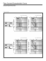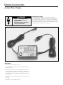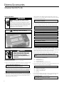
1
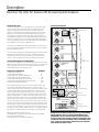
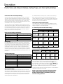
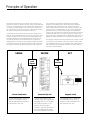
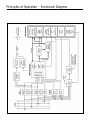
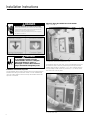
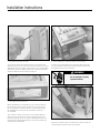
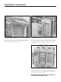
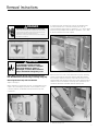
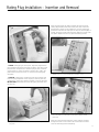
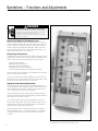
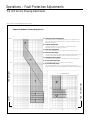
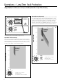
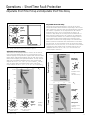
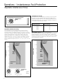
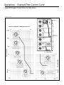
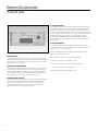
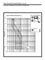
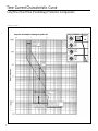
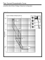
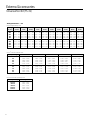
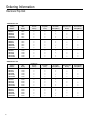
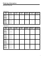
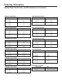
Electronic Trip Unit for
SB Encased Systems Breakers
Information and Instruction Guide
DANGER
Hazardous voltage. WIll cuase death of serious injury.
Turn off and lock out all power supplying the device prior
to cover(s) removal or while cover(s) are removed and
when installing any internal or external accessory.
Replace the cover(s) and shield(s) before power supplying
this device is turned on.
Circuit breaker indicators shown in this booklet are for illustration purposes only. Circuit
breakers are to be installed in “Discharged” and “Open” positions only.
IMPORTANT
The information contained herein is general in nature and not intended for specific application purposes. It does not relieve the user of responsibility to use sound practices in
application, installation, operation, and maintenance of the equipment purchased. Siemens
reserves the right to make changes in the specifications shown herein or to make improvements at any time without notice or obligations. Should a conflict arise between the general
information contained in this publication and the contents of drawings or supplementary
material or both, the latter shall take precedence.
NOTE
*Authorized and qualified personnel —
For the purpose of this manual a qualified person is one who is familiar with the installation,
construction or operation of the equipment and the hazards involved. In addition, he has the
following qualifications:
(a) is trained and authorized to de-energize, clear, ground, and tag circuits and equipment
in accordance with established safety practices.
(b) is trained in the correct care and use of protective equipment such as rubber gloves,
hard hat, safety glasses or face shields, flash clothing, etc., in accordance with established safety practices.
(c) is trained in rendering first aid.
SUMMARY
These instructions do not purport to cover all details or variations in equipment, nor to
provide for every possible contingency to be met in connection with installation, operation,
or maintenance. Should further information be desired or should particular problems arise
which are not covered sufficiently for the purchaser’s purposes, the matter should be
referred to the local sales office, listed on back of this instruction guide.
The contents of this instruction manual should not become part of or modify any prior
or existing agreement, commitment or relationship. The sales contract contains the entire
obligation of Siemens Energy & Automation, Inc. The warranty contained in the contract
between the parties is the sole warranty of Siemens Energy & Automation, Inc. Any statements contained herein do not create new warranties or modify the existing warranty.
Electronic Trip Unit for Siemens Type SB Systems Breakers
Table of Contents
Information and Instructions
Electronic Trip Unit
Overcurrent Protection Configurations
RMS Current Sensing
Systems Breaker Frame Sizes
Systems Breaker Frame Ampere Ratings
Rating Plugs
Principles of Operation
Functional Diagram
2-5
2
2
3
3
3
3
4
5
Installation Instructions
Installing the Trip Unit
Removing the Trip Unit
Removing/Replacing Plexiglass Cover
Inserting/Removing the Rating Plug
6-11
6-8
9
10-11
10-11
Operations
Electronic Trip Unit Functions
Setting the Fault Protection Adjustments
Current Shaping Fault Protection Adjustments
Long Time Fault Protection
Short Time Fault Protection
Instantaneous Fault Protection
Ground Fault Protection
Ground Fault Sensing Schemes
Example Time Current Curve (4000A)
Standard Test and Monitoring Functions
Systems Check Indicator
Trip Status Indicator Lights
Integral Test Modes
Optional Functions
Ground Fault Monitor
Display Module (Current Monitoring)
12-21
12
12
13
14
15
16
17
18
19
20
20
20
20
21
21
22
Time Current Characteristic Curves
23-31
Accessories
Universal Test Kit (TS-31)
32-35
32-35
Ordering and Catalog Information
Electronic Trip Unit
Rating Plugs
Universal Test Kit (TS-31)
Auxiliary Power Module
Neutral Transformers
36-38
36
38
38
38
38
UL Listings and File Numbers
39
NOTE: Information related to specific catalog numbers does not guarantee product availability. Technical information
may change due to product revisions. Consult Siemens sales office concerning any variation of product information
contained herein.
1
Description
Electronic Trip Units For Siemens SB Encased Systems Breakers
Electronic Trip Unit
The Electronic Trip Unit is a microprocessor controlled multifunction overcurrent protective device for application with
Siemens state-of-the art family of SB Encased Systems
Breakers. The adjustment flexibility provided by the trip unit
allows the user to easily accommodate load changes and
other protective requirements while still assuring optimum
coordination. In addition to the adjustable protection functions,
the unit is designed to use field interchangeable rating plugs.
These ratings plugs allow the ampere rating of the breaker to
be changed to meet specific applications.
For ease of installation and interchangeability in the field, the
trip unit has been designed as a plug-in unit to mount directly
into a SB breaker frame.
Full Function Trip Unit
Ir =% In
70
80
50
100
8
Protection Configuration
Long Time/Short Time
Long Time/Instantaneous
Long Time/Short Time/Instantaneous
Long Time/Short Time/Ground Fault
Long Time/Instantaneous/Ground Fault
Long/Short Time/Instantaneous/Ground Fault
Fixed Long Time/Instantaneous
Identifier
LS
LI
LSI
LSG
LIG
LSIG
MLI
14
17
4
2.5
25
3
3.5
2.5
4
2
Additional optional features include:
Display Module for local current monitoring (field addable)
Zone Selective Interlocking
Communications for remove monitoring
2
Short
Time
Pickup
5
xln
6
8
7
Fixed .2
.3
.15
Long
Time
Delay
Secs
@6 x ln
21
30
.07 Short
.1
.1
Time
Delay
Secs
.3
4
.2
.15 @8 x ln
Curve
Adjustments
I2t
5
Instantaneous
Pickup
6
3
2
7
xln
8
1.5
10
23
9
24
25
22
21
26
20
28
.5
.3
.1
.2
.2
.1
MAX RATING
= 2000A
Ground
Fault
Delay
Secs
@1000A
.3
.4
Ground
Fault
Pickup
lg=% MAX
RATING
27
30
Fixed .4
.5
As standard features, the trip unit has two built-in-test functions and a fault identification function. System Check is a
built-in-test function that continuously checks the status of the
microprocessor and protective algorithms. A green LED on
the front panel blinks approximately every 3 seconds when
the microprocessor is correctly cycling through its protection
routines. Integral Test is a built-in-test that allows the user to
exercise the trip unit electronics. LED indicators display the
testing status. Trip Status is a fault identificaton function that
stores information when a fault current causes the trip unit to
trip the circuit breaker. By pressing the Query button the user
can display the cause of the breaker trip by illuminating one of
four LED’s: OL (overload), ST (short time), SC (short circuit), or
GF (ground fault). Newer version trip units are equipped with a
Trip Status LED Reset Button for resetting the trip indicator.
SYSTEM
CHECK
95
10
5.5
Rating Plug
ln = 1000A
90
.07
Overcurrent Protection Configurations
Trip units are available in seven overcurrent protection configurations to meet specific protection requirements. Six trip units
have Adjustable Continuous Current and Long Time Delay.
Optional protection configurations are:
SIEMENS
Rating Plug
85
60
1.5
Current sensors within the SB breakers provide signal currents
and operating power for the trip unit. Therefore, when the
breaker is closed, the trip unit requires no external connections or control power to perform its protection functions.
Continuous
75
65
I 2t
Trip
Status
Query
O.L.
S.T.
S.C.
G.F.
Fault Indicators
APM
Pass
Testing
TEST
Trip
Phase
G.F.
Built-in
Test Functions
TS31
Display
Module
IA
Meter
IB
IC
Maximum Demand
Present Demand
60
100
70
90
Amps
80
Load Monitor
Alarm Set Points
% Continuous Amps
Plug-in
Display Module
NOTE: Earlier model trip units may use (lr) as the Rating
Plug designator and (In) to denote (MAX Rating). The
designations for the current model trip unit are shown
above. Note however, that the change in designation has
no effect on the switch settings used for selecting continuous, Long Time, Short Time, Instantaneous and Ground
Fault pickup and delay values.
Description
Frame Sizes and Ampere Ratings, Rating Plugs, and Interrupting Ratings
Frame Sizes and Frame Ampere Ratings
Siemens SB Encased Systems Breakers come in six frame
sizes with frame ampere ratings ranging from 400 to 5000
amperes. All frames are rated for 100% continuous operation.
The max ampere rating is determined by the current transformers within the frame. Correctly rated electronic trip units
are available for all SB systems breakers.
Trip units are fully field installable by authorized personnel. A
special rejection scheme is built into the frames and trip units
to prevent the installation of a trip unit into a frame for which
it is not intended. The two-pin rejection scheme is shown on
page 7. The combinations of frame sizes and frame ampere
ratings are listed in the following table.
Frame Size and Rating Combinations
Breaker Frame Ampere Size
Breaker Max Ampere Rating
1200 Amperes
(SBA, SBS only)
2000 Amperes
3200 Amperes
5000 Amperes
400, 800, 1200
800 (SBH only), 1200, 1600, 2000
2500, 3200
2500, 3200, 4000, 5000
Rating Plugs
Field interchangeable rating plugs are used to set the effective ampere rating of the circuit breaker. Available rating plugs,
as a function of the frame ampere ratings, are given in the
following table. Note that the maximum rating plug value for
a particular electronic trip unit is equal to the frame rating;
the minimum is equal to 50% of the MAX Rating. A rejection
scheme is built into the rating plugs and trip units to prevent
the insertion of a rating plug into a trip unit for which it is not
intended.
Available Rating Plugs
Ampere Rating
400
800
1200
1600
2000
2500
3200
4000
5000
Rating Plug Ampere Values (In)
200, 225, 250, 300, 350, 400
400, 450, 500, 600, 700, 800
600, 700, 800, 1000, 1200
800, 1000, 1200, 1600
1000, 1200, 1600, 2000
1600, 2000, 2500
1600, 2000, 2500, 3000, 3200
2000, 2500, 3000, 3200, 4000
2500, 3000, 3200, 4000, 5000
RMS Current Sensing
The Siemens microprocessor-controlled Electronic Trip Unit
executes the overcurrent fault protection functions of Siemens
SB Encased Systems Breakers. The adjustment flexibility provided by the trip unit allows the user to easily accommodate
load changes and other protection requirements while still
assuring optimum coordination.
A standard feature of the trip unit is RMS current sensing.
RMS sensing measures the true heating potential of the
current waveform. This allows for more accurate overcurrent
protection and eliminates nuisance tripping due to harmonic
distortion of the current waveform.
Interruption and Short Time Ratings
Four short circuit interruption ratings are available to meet
specific applications. The interruption ratings and short time
ratings are given in the following table:
UL 489 Interruption and Short Time Ratings
Breaker Frame Size
1200
2000
3200
Type SBA Alternative Interrupt Rating (Blue Label)
240V AC
65 kA
85 kA
480V AC
65 kA
65 kA
—
600V AC
42 kA
50 kA
Type SBS Standard Interrupt Rating (Black Label)
240V AC
100 kA
150 kA
150 kA
480V AC
100 kA
100 kA
100 kA
600V AC
50 kA
65 kA
85 kA
Type SBH High Interrupt Rating (Red Label)
240V AC
200 kA
200 kA
480V AC
—
150 kA
150 kA
600V AC
100 kA
100 kA
Short Time Rating (t=0.5 seconds)
25 kA
35 kA
50 kA
5000
—
150 kA
100 kA
85 kA
200 kA
150 kA
100 kA
65 kA
IEC 947-2 Ratings (SBS Units Only)
Frame Sizes
Voltage 50/60 Hz
1200
2000
3200
Type SBS Standard Interrupt Rating (Black Label)
415V AC lcu
100 kA
100 kA
100 kA
lcs
100 kA
100 kA
100 kA
lcw
25 kA
35 kA
50 kA
690V AC lcu
65 kA
65 kA
65 kA
lcs
65 kA
65 kA
65 kA
lcw
25 kA
35 kA
50 kA
5000
100 kA
100 kA
65 kA
65 kA
65 kA
65 kA
The interruption rating of the SB breaker is specified on the
front cover label, and is further identified by the use of a
“color bar” at the top left of the breaker label. Blue indicates
the “alternate” or the lowest interrupting category. Black indicates the “standard” interrupting rating. A Red label indicates
the highest available interrupting rating for the SB breaker.
The trip unit that may be used with a specific circuit breaker is
identified on the front cover label.
NOTE: For trip units not requiring full-function adjustability, integral testing functions, local indication, or
ACCESS communications compatibility, specify trip
unit with catalog suffix MLI.
3
Principles of Operation
The Siemens Electronic Trip Unit utilizes a microprocessor to
execute the myriad of numeric and logic functions programmed
in the unit. The adjustments on the trip unit face allow the user
to select the numerical values to be used by the microprocessor in performing its protection function. (The numerical values
are stored in the processor’s permanent memory.)
Current data is derived from current sensors mounted in the
Siemens SB Systems Breaker. These sensors are current transformers. As passive devices they provide high reliability with
minimum signal error, while providing power for the trip unit.
The current signals from the transformers are converted to
digital voltages in the trip unit. These digital voltages are stored
in temporary memory. The digital signals are used by the microprocessor in detecting and processing overcurrent conditions.
SENSE
The microprocessor reads the temporarily stored digital
voltages and compares these values with the permanently
stored values that correspond to the user-selected adjustment settings. When an overcurrent condition is detected, the
microprocessor’s software begins to process the appropriate
protection function. During the processing of the protection
function, the microprocessor continues to monitor the incoming
current level data. If the overcurrent condition continues until
the processing is completed and the appropriate delay time has
elapsed, a tripping command is issued by the microprocessor.
The tripping command from the microprocessor causes a signal
to be sent from the electronic trip unit to the low energy, high
speed magnetic latch in the circuit breaker. The signal in the trip
unit counteracts the permanent magnet in the latch, allowing
the latch to trip the breaker.
Current
Level
Signals
Current Transformers
Current transformers sense the
levels of the phase currents
and provide data and power to
the electronic trip unit.
4
ACT
DECIDE
Trip
Command
Electronic Trip Unit
The trip unit monitors the
current levels at an equivalent
sampling rate of 353 samples
per cycle per phase. In the
event of an overcurrent
condition, the trip unit’s microprocessor determines when
the circuit breaker should trip.
Magnetic Latch
The magnetic latch causes the
circuit breaker to trip when it
receives a trip command from
the electronic trip unit.
Principles of Operation – Functional Diagram
5
Installation Instructions
DANGER
Electronic Trip Unit Installed into Circuit Breaker
Steps 1 through 9.
Hazardous Voltage. Will cause death or serious injury.
Turn off and lock out all power supplying the device prior to
cover(s) removal or while cover(s) are removed and when
installing any internal or external accessory.
Replace the cover(s) and shield(s) before power supplying
this device is turned on.
�
�
�
�
�
�
�
�
�
�
CAUTION
Do not attempt to install a trip unit
with the breaker “Closed” or “Charged”
.
Make certain breaker is “Open” or
“Discharged” as shown above. Personal
injury or mechanical damage may occur.
Installation of Electronic Trip Unit
The SB breaker has a built-in interlock device that prevents the
breaker from being closed when there is not an installed trip
unit. This same interlock device will trip the breaker when the
trip unit is removed.
�
�
�
�
1. Remove 8 screws from breaker front cover.
To install the trip unit, the front cover of the breaker must first
be removed. This is done by removing the four (4) recessed
Phillips head screws in positions 2, 3, 6, and 7, along with the
four (4) Phillips head screws in positions 1, 4, 5, and 8, which
hold the front cover in place.
2. Lift off front cover.
6
�
�
Installation Instructions
3. Set ground fault selection switch.
5. Check alignment of “rejection-scheme” pins with holes.
On trip units with ground fault protection, the ground fault
selection switch on the side of the trip unit must be set to the
appropriate sensing scheme—Residual or Source Ground/Zero
Sequence—prior to installing the trip unit. These ground fault
sensing schemes are discussed on page 18.
If there is any doubt about a trip unit being the correct trip
unit for a breaker, hold the trip unit upside down and check
the alignment of the pins and holes.
WARNING
Do not attempt to modify
rejection features.
4. Check label on side of trip unit.
Before attempting to install the trip unit, check the label on
the side of the unit to make sure that it is the correct unit
for the SB breaker. A built-in rejection scheme will prevent
the installation of a trip unit into a breaker for which it is
not intended.
This scheme consists of two pins on the support plate on
which the trip unit will set into two matching holes in the
bottom of the trip unit. If the holes in the bottom of the trip
unit cannot be aligned with the pins, the trip unit cannot be
installed in the SB breaker.
6. Mate pin connectors.
Mate the connector half on the back of the trip unit with its
corresponding connector half in the breaker.
7
Installation Instructions
7. Lower trip unit onto support plate.
8. Secure trip unit.
After the connector has been mated, lower (push) the trip unit
onto the support plate. The pins on the support plate will fit
into the holes in the bottom of the trip unit.
Secure the trip unit in place with the retaining screw located
at the top of the trip unit. Torque 6 and 8 in-lbs. If trip unit top
is not secured correctly, the interlock will prohibit closing of
the breaker.
9. Replace the front cover.
Replace the front cover. Then, replace the eight (8) front cover
screws. If trip unit top is not secured correctly, the interlock
will prohibit closing of the breaker.
NOTE: Before energizing breaker be sure to install a correct rating plug. See pages 10 and 11.
8
Removal Instructions
DANGER
Hazardous Voltage. Will cause death or serious injury.
Turn off and lock out all power supplying the device prior to
cover(s) removal or while cover(s) are removed and when
installing any internal or external accessory.
To remove the trip unit the front cover of the breaker must
first be removed. This is done by removing the four (4)
recessed Phillips head screws in positions 2, 3, 6, and 7, along
with the four (4) Phillips head screws in positions 1, 4, 5, and
8, which hold the front cover in place.
Replace the cover(s) and shield(s) before power supplying
this device is turned on.
CAUTION
Do not attempt to install a trip unit
with the breaker “Closed” or “Charged”
.
Make certain breaker is “Open” or
“Discharged” as shown above. Personal
injury or mechanical damage may occur.
NOTE: When practical, the trip unit should be removed
from the SB breaker when removing or inserting rating plug.
Removing Electronic Trip Unit from Breaker
Steps 1 through 3.
2. Remove the trip unit retaining screw.
Remove the front cover of the breaker and trip unit retaining
screw. Lift the trip unit from the support plate and unmate
the connector. Note that the trip unit must be lifted from the
support plate high enough for the pins on the support plate to
clear the holes in the bottom of the trip unit; otherwise, the
connector cannot be unmated. Remove the trip unit.
Before starting to remove the trip unit, set the breaker to the
“Open” and “Discharged” positions. If the breaker is in the
“Closed” position, the breaker will trip when the trip unit
is removed.
�
�
�
�
�
�
�
�
�
�
�
�
�
�
�
�
1. Remove 8 screws from breaker front cover and lift off.
3. Remove the trip unit.
9
Rating Plug Installation – Insertion and Removal
DANGER
Hazardous Voltage. Will cause death or serious injury.
Turn off and lock out all power supplying the device prior to
cover(s) removal or while cover(s) are removed and when
installing any internal or external accessory.
Replace the cover(s) and shield(s) before power supplying
this device is turned on.
1. Check label on the rating plug.
Before attempting to insert the rating plug, check the label on
the rating plug label to verify that it is the correct plug for the
trip unit. If it is not a correct plug, the pins on the plug will not
mate with the receptacle in the trip unit.
CAUTION
Do not attempt to remove a rating plug
with the breaker “Closed”. Make certain
breaker is “Open” as shown above to
prevent inadvertent interruption of
service.
CAUTION
Do not attempt to force incorrect
rating plug into trip unit.
2. Remove two (2) retaining screws from the plexiglass cover.
Inserting and Removing Rating Plug from Trip Unit
Steps 1 through 7.
Prior to inserting or removing a rating plug, check to see that
the breaker is in the “Open” position. The breaker should
always be in the “Open” position when a rating plug is not in
the trip unit. The trip unit will default to the lowest possible
settings if a rating plug is not installed.
Inserting and removing the rating plug requires the removal of
the clear plexiglass cover. To remove the cover, unscrew the
two screws that hold it in place, gently pry one end of the
cover loose with a small screwdriver, and lift off.
To prevent the insertion of a rating plug into a trip unit for
which it is not intended, the rating plug connector on the trip
unit has been keyed to reject incorrect plugs.
3. Remove plexiglass cover.
10
Rating Plug Installation – Insertion and Removal
After the rating plug has been inserted and the necessary
setting adjustments have been made (see Fault Protection
Adjustments, pages 13-18), replace the cover by sliding the
protective cover into the top lip of the trip unit, bow slightly in
middle, and press down with thumb on bottom to snap cover
into place. Replace the two (2) special retaining screws.
4. Squeeze plug clips to insert or remove from trip unit.
To insert a rating plug in the trip unit, align the plug with the
plug receptacle and press the plug into place. The clips on the
plug and the compression fit hold the plug in place, eliminating the need for screws or latches. The plug will “snap” into
place without excessive force. Do not force the rating plug
into place.
6. Replace two (2) screws retaining the plexiglass cover.
To remove a rating plug, squeeze the clips and pull the plug
from the plug receptacle. Since the plug is held in place by
compression, some force will be required to remove the plug.
Do not close the breaker with the rating plug removed from
the trip unit.
7. The cover may be sealed with a lead seal for tamper evident
protection.
5. To replace the cover, bow slightly in the middle, and snap
into place.
After the cover has been replaced, a wire may be inserted
through the holes in the screws and secured with a meter
seal. This will help prevent tampering.
11
Operations – Functions and Adjustments
DANGER
Hazardous Voltage. Will cause death or serious injury.
Turn off and lock out all power supplying the device prior to
cover(s) removal or while cover(s) are removed and when
installing any internal or external accessory.
Replace the cover(s) and shield(s) before power supplying
this device is turned on.
Removing and Replacing the Plexiglass Cover
To remove the plexiglass cover, loosen the two screws that
hold it in place and gently pry one end of the cover loose with
a small screwdriver. After the rating plug has been installed
and any necessary adjustments have been made, the cover
must be replaced to prevent unauthorized adjustments. (See
pages 10 and 11, steps 2, 3, 5, 6, and 7).
Electronic Trip Unit Functions
Displayed and accessible on the front panel of the trip unit are
adjustments, switches, and indicators that are available to the
user for local control, test, and monitoring. These include:
•
•
•
•
•
System Check Indicator
Fault Protection Adjustments
Trip Query Switch and Indicators
Integral Test Switches and Indicators
Current Demand Indicators (Display Module Option)
Also accessible on the front panel is a receptacle for an external test set and power supply.
The trip unit has factory-installed capability for zone selective
interlocking and communications for remote monitoring. These
functions are accessible via the TS-31 test port.
Setting the Fault Protection Adjustments
The Electronic Trip Unit executes its overcurrent protection
functions based on the rating plug value and the setting of the
current adjustments. Therefore, care should be taken by the
user to make correct selections and settings.
To avoid potential nuisance tripping while changing settings,
Siemens recommends that all adjustments be made with the
SB breaker in the “Open” position.
To set an adjustment, place a slotted screwdriver onto the
point-to-point adjustment switch and rotate the switch to the
desired setting. The following figures and test illustrate and
describe the fault protection adjustments.
All pick-up adjustments, except ground fault, are multiples
of the rating plug value, In. Ground fault pick-up is a multiple
of the MAX rating. All pick-up settings are RMS amperes
or values.
2000A Electronic Trip Unit adjustment panel with plexiglass cover
removed and access adjustment switches shown.
12
Operations – Fault Protection Adjustments
Trip Unit Current Shaping Adjustments
(This curve is for illustration purposes only)
Amperes in Multiples of Rating Plug Value (In)
0.1
1
10,000
(1) Continuous Ampere Setting Region
The allowable continuous operating amperes is set to a percent of the
rating plug value. Note that the maximum continuous ampere is set by
the rating plug value, In.
1
(2) Long Time Delay Region
The long time delay is set to an inverse I2t ramp function delay
calibrated at 6 times the rating plug value, In .
(3) Short Time Pickup Region
The short time pickup is set to a multiple of the rating plug value, In .
1,000
(4) Short Time Delay Region
The short time delay is set to either a fixed delay (illustrated) or an inverse
I2t ramp function delay calibrated at 8 times the rating plug value, In.
(5) Instantaneous Pickup Region
The instantaneous pickup is set to a multiple of the rating plug value, In.
2
(6) Ground Fault Pickup Region
Ground fault pickup is set to a percent of the max rating.
(7) Ground Fault Delay Region
The ground fault delay is set to either a fixed delay (illustrated) or an
inverse I2t ramp function delay calibrated at one half of the MAX rating.
lg = % MAX Rating
10
10
3
1
1
4
1 Cycle
7
0.1
0.1
5
0.01
10
100
Time in Seconds
6
1 Cycle
Time in Seconds
100
0.01
1000
13
Operations – Long Time Fault Protection
Adjustable Continuous Amps and Adjustable Long Time Delay
Ir =%In
70
Continuous
75
65
85
50
SIEMENS
Rating Plug
80
60
ln = 2000A
90
100
8
14
17
4
2.5
21
30
SYSTEM
CHECK
95
10
5.5
25
Adjustable Long Time Delay
The Long Time Pickup is nominally set at 115% of the continuous amps setting. The Long Time Delay adjustment is used
to set the tripping delay of the SB breaker based on the magnitude of the overcurrent condition. On Siemens Electronic
Trip Units, the long time delay, which is an inverse I2t ramp
function, may be set to a calibrated value of 2.5, 4, 5.5, 8, 10,
14, 17, 21, 25, or 30 seconds at a current equal to 6 times In.
Long
Time
Delay
0.1
1
10
100
10,000
Continuous
Operating
Current
Secs
@6 x ln
2000A Rating Plug Used for Illustrative Purposes Only
Adjustable Continuous Amps
The Continuous Ampere Adjustment sets the current level at
which the breaker will continuously operate without initiating a
tripping sequence. On Siemens Electronic Trip Units, the continuous operating current may be set to 50, 60, 65, 70, 75, 80,
85, 90, 95, and 100% of the rating plug value In.
0.1
1
10
100
10,000
Time In Seconds
1,000
100
Long
Time
Delay
10
1
xln
Continuous
Operating
Current
0.1
Time In Seconds
1,000
0.01
100
8
14
17
4
10
2.5
21
30
0.1
70
75
80
65
85
60
50
90
100
25
Long Time Delay
1
95
Continuous Operating Current
14
10
5.5
Available Switch Settings
(All Frame Sizes)
for Adjustable Continuous Amps
Long
Time
Delay
Secs
@ 6xl n
Available Switch Settings
(All Frame Sizes)
for Adjustable Long Time
xln
Operations – Short Time Fault Protection
Adjustable Short Time Pickup and Adjustable Short Time Delay
Adjustable Short Time Delay
The Short Time Delay adjustment is used to set the time
interval the breaker will wait before responding to the current
value selected on the Short Time Pickup adjustment. There are
two modes of operation of this adjustment on all Siemens
Electronic Trip Units; one is a fixed delay, the other is an
inverse I2t ramp delay. The I2t Delay has the characteristic of
being inversely proportional to the square of the magnitude
of the overcurrent condition. This means that higher overcurrent conditions have shorter delays and conversely lower
overcurrent conditions have longer delays. This characteristic
allows for better coordination with downstream circuit breakers and fuses. In the fixed delay mode, the Short Time Delay
may be set to 0.07, 0.1, 0.15, 0.2, or 0.3 seconds. In the inverse
I2t ramp Short Time Delay mode, the delay may be set to a
calibrated value of 0.07, 0.1, 0.15, 0.2, or 0.3 seconds at a
current equal to 8 times In.
3.5
2.5
4
Short
Time
5 Pickup
2
1.5
6
8
ln
7
.3
Fixed .2
.15
.07 Short
.1
.1
.15 Secs
@8 x ln
2
.07
.3
Time
Delay
It
.2
800 – 2000A Short Time Pickup for Illustrative Purposes
Adjustable Short Time Pickup
The Short Time Pickup adjustment is used to set the level of
high current the breaker will carry for a short period of time
without tripping. This adjustment, together with the Short Time
Delay, allows downstream breakers time to clear short circuit
faults without tripping the upstream breakers. On trip units for
800, 1200, and 2000A SB breaker sizes, Short Time Pickup
may be set to 1.5, 2, 2.5, 3, 4, 5, 6, 7, 8, or 9 times In. On trip
units for 3200, 4000, and 5000A frame sizes, Short Time
Pickup may be set to 1.5, 2, 2.5, 3, 3.5, 4, 5, 6, 7, or 8 times In.
0.1
1
10,000
10
100
xln
Continuous
Operating
Current
1,000
0.1
10
1
10,000
100
Continuous
Operating
Current
1,000
Time In Seconds
3
xln
Short Time
Fixed Delay
.2
100
10
.3
.15
Long
Time
Delay
.1
.07
Short
Time
Pickup
1
Available Switch
Settings
(All Frame Sizes)
0.1
Time In Seconds
100
Short Time
Fixed Delay
Long
Time
Delay
10
0.01
0.1
1
0.01
4
2.5
2
1.5
3
5
2.5
6
7
9
8
800, 1200, 2000A
Frame Sizes
Short Time Pickup
2
1.5
3.5
4
Short
Time
5 Pickup
6
8
7
3200, 4000, 5000A
Frame Sizes
xln
Available
Switch
Settings
Time In Seconds
100
10
1
10
xln
Short Time
l2t Delay
Long
Time
Delay
Short
Time
Pickup
0.1
0.01
100
Continuous
Operating
Current
1,000
Short
Time
Pickup
0.1
3
1
10,000
Short Time
2
l t Delay
.07
.1
.15
.3
.2
I2t
Secs @ 8 x In
Available Switch
Settings
(All Frame Sizes)
Short Time Delay
15
Operations – Instantaneous Fault Protection
Adjustable Instantaneous Pickup
Instantaneous Override
On all trip units, an instantaneous override function has been
provided. It is set nominally at the short time rating of the
respective breaker frame size. This allows the breaker to ride
through high faults up to its short time capability; however, it
is self-protecting above these values.
5
4
Instantaneous
Pickup
6
3
2
xln
7
8
1.5
12
10
Short Time kA Rating
(t = 0.5 seconds)
Breaker Frame Size
1200A
2000A
3200A
5000A
800 – 2000A Instantaneous Pickup for Illustrative Purposes
Adjustable Instantaneous Pickup
The Instantaneous Pickup adjustment is used to set the
current level at which the breaker will trip without an intentional time delay. Non-delayed tripping, as a result of a severe
overcurrent condition, minimizes potential damage to electrical
systems and equipment. On trip units for 800, 1200, and
2000A SB breaker sizes, Instantaneous Pickup adjustment
may be set to 1.5, 2, 3, 4, 5, 6, 7, 8, 10, or 12 times In. On trip
units for 3200, 4000, and 5000A frame sizes, Instantaneous
Pickup adjustment may be set to 1.5, 2, 3, 4, 5, 6, 7, 8, 9, or 10
times In.
25
35
50
65
Discriminator Circuit (Making Current Release)
This circuit overrides the short time delay function should the
breaker attempt to close into a faulted system, tripping the
breaker instantaneously. This discriminatory function is enabled
for the first 6 cycles of current flow, after which normal short
time characteristics operate.
0.1
1
10,000
0.1
1
10,000
10
100
100
Continuous
Operating
Current
xln
Continuous
Operating
Current
10
1,000
Time In Seconds
Time In Seconds
1,000
100
Long
Time
Delay
10
100
Long
Time
Delay
10
1
Short
Time
Pickup
0.1
Short Time
Fixed Delay
1
Instantaneous
0.1 Pickup
0.01
Instantaneous
Override
0.01
4
5
4
6
3
2
8
1.5
12
10
800, 1200, 2000A
Frame Sizes
Instantaneous Pickup
16
Instantaneous
Pickup
6
3
7
Instantaneous Override (Illustrated with Short Time Fixed Delay)
5
2
7
xln
8
1.5
10
9
3200, 4000, 5000A
Frame Sizes
Available
Switch
Settings
xln
Operations – Ground Fault Protection
Adjustable Ground Fault Pickup and Adjustable Ground Fault Delay
23
and erratic. Time constants for the current integration are preset within the unit as a function of the Ground Fault Delay.
24
25
21
20
lg= % MAX
RATING
27
30
Fixed .4
28
.5
.3
Ground Fault Sensing Schemes
The trip unit can be configured to accommodate the following
ground fault sensing schemes:
MAX RATING
= 2000A
• 3-Phase, 3-Wire Residual
• 3-Phase, 4-Wire Residual
• Source Ground
.1
Ground
Fault
.2
Delay
.2
.1
.3
.5
I2 t
.4
Secs
@1000A
Adjustable Ground Fault Pickup
The Ground Fault Pickup adjustment is used to set the level
of ground current at which circuit interruption will be initiated.
Together with the Ground Fault Delay, this adjustment allows
selective tripping between main and feeder or other downstream breakers. The available ground fault pickup settings as
a percent of the SB breaker MAX ampere rating are listed
below. In compliance with the National Electric Code (NEC
230-95), no trip point setting exceeds 1200A.
MAX Rating
400A
800A
1200A
1600A
2000A
2500A
3200A
4000A
5000A
Available Setting = %MAX Rating
20
20
20
20
20
20
20
20
25
25
25
26
23
23
21
21
––
30 40 50 60 70 80
30 40 50 60 70 80
30 40 50 60 70 80
32 38 44 50 56 62
27 30 35 40 45 50
26 29 32 35 38 41
23 25 27 29 31 33
22 23 24 25 26 27
– (SETTING FIXED AT 1200A) –
90 100
90 100
90 100
68 75
55 60
44 48
35 37
28 30
––
Adjustable Ground Fault Delay
The Ground Fault Delay adjustment is used to set the time
interval the breaker will wait before responding once the
ground fault pickup level has been reached. There are two
modes of operation for this adjustment for Siemens Electronic
Trip Units; one is a fixed delay and the other is an inverse I2t
ramp delay. In the fixed delay mode, the Ground Fault Delay
may be set to 0.1, 0.2, 0.3, 0.4, or 0.5 seconds. In the inverse
I2t ramp delay mode, the delay may be set to a calibrated
value of 0.1, 0.2, 0.3, 0.4, or 0.5 seconds at a current equal to
0.5 times the MAX rating. The inverse I2t ramp delay reverts to
a fixed delay of the same value when the ground current (Ig)
exceeds 50 percent of the MAX rating.
Ground Fault Memory Circuit
Electronic Trip Units with ground fault protection come
equipped with a ground fault memory circuit. This circuit integrates ground fault currents with time. This provides added
protection by preventing ground fault delay circuits from being
reset to zero when the ground fault currents are intermittent
All that is required of the user to configure the trip unit to
support these protection schemes is to set the ground fault
selection switch to the desired configuration. The selection
switch is on the right side of newer version trip units and the
left side of earlier versions. The selection switch must be set
prior to the trip unit being installed in the SB breaker.
10
0.1
1
10
100
Ground
Fault
Pickup
Time In Seconds
Ground
Fault
26 Pickup
xln
Fixed Ground
Fault Delay
.4
1
.5
.3
.2
.1
Available Switch
Settings
(All Farme Sizes)
0.1
Ground Fault
Fixed Delay
0.01
0.1
1
10
100
xln
10
Ground
Fault
Pickup
Time In Seconds
22
Adjustable Ground
Fault 12t Delay
.1
1
.2
.3
.5
.4
I2t
Secs
@.5 MAX
Rating
0.1
Ground Fault
l2t Delay
Available Switch
Settings
(All Farme Sizes)
0.01
Ground Fault Delay
17
Operations – Ground Fault Sensing Schemes
Ground Fault Sensing Scheme
The following are brief descriptions of the ground fault sensing
schemes as they relate to the Siemens Electronic Trip Unit.
Detailed technical and application information of the ground
fault sensing schemes is contained in NEMA Standard No.
PB 2.2 “Application Guide for Ground Fault Protective Devices
for Equipment”.
Source Ground: In this scheme, the phase currents are not
used in detecting and processing ground faults. The trip unit
executes the ground fault protection function based on data
from a ground current sensor. This sensor is located on the
neutral connection to ground at the service entrance, and is
connected to the neutral transformer input terminals on the
trip unit.
Residual (3-Phase, 3-Wire): Under normal system conditions
(without ground fault), the vector sum of the phase currents
being monitored by the trip unit is zero. This is also true under
the condition of an overcurrent phase-to-phase fault and
phase-unbalance condition. When a phase-to-ground fault
occurs, the vector sum of the phase currents is directly
proportional to the magnitude of the fault. The trip unit’s
microprocessor uses this vector sum data in the execution
of the ground fault protection function. The trip unit utilizes
the internal breaker current transformers. No external current
transformers are required.
Residual (3-Phase, 4-Wire): In the 3-Phase, 4-Wire Residual
scheme a fourth current transformer is connected in the
neutral conductor to “Sense” normal neutral currents. Under
normal system conditions, the vector sum of the currents in
all phases equals the neutral current. This is also true under
the condition of an overcurrent phase-to-phase fault and
phase-unbalance condition. When a phase-to-ground fault
occurs, the fault current returns via a path other than the neutral. Therefore, the vector sum of the phase currents no longer
equals the neutral current. This current differential is detected
by the trip unit and used in the execution of the ground fault
protection function.
Source Ground Current
Residual Sensing: Circuit Breaker Wiring for Ground Protection
(3-Phase, 4-Wire System Shown)
18
Zero Sequence Ground Fault Protection
Operations – Example Time Current Curve
Type SB Breaker Frame Time Current Curve
Example: 2000A
Ir =%In
70
80
50
14
17
4
2.5
21
30
25
3
4
2.5
5
2
Long
Time
Delay
Secs
@6 x ln
Short
Time
6 Pickup
1.5
xln
7
9
Fixed .2
.15
8
.3
.1
4
Time
Delay
Curve
Adjustments
.15 Secs
@8 x ln
2
.07
.3
MAX
RATING
.07 Short
.1
It
.2
5
Instantaneous
Pickup
6
3
2
7
xln
1000A
8
1.5
10
30
9
35
40
27
23
Ground
Fault
45 Pickup
lg= %
50
20
60
Fixed .4
.1
.2
.2
.1
.3
.4
I2t
Ground
Fault
Delay
Secs
@
1 Cycle
1 Cycle
Time in Seconds
.5
MAX RATING
= 2000A
55
.5
.3
Time in Seconds
SYSTEM
CHECK
95
10
5.5
Rating Plug
ln = 1000A
90
100
8
SIEMENS
Rating Plug
85
60
Amperes in Multiples of Rating Plug Value (In)
Continuous
75
65
19
Operating Instructions
Part Three – Monitoring the Electronic Trip Unit
Trip Unit Test and Monitoring Functions
Siemens Electronic Trip Unit is equipped with three standard
test and monitoring functions to aid the user in the installation
and operation of the SB breaker.
Integral Test Modes
APM
Pass
Testing
System Check Indicator
TEST
Trip
Ir =%In
70
Continuous
75
65
80
85
60
50
SIEMENS
SYSTEM
CHECK
95
The trip unit derives its operating power from the phase currents
in the SB breaker. The phase current required to operate the trip
unit is approximately 20% of the MAX rating. If the microprocessor is not correctly cycling through its protection routines, the
phase current is below 20% (MAX rating), the LED will not light.
Trip Status
Trip
Status
O.L.
S.T.
S.C.
G.F.
NOTE: A Trip Status Reset Button is provided on newer
version trip units.
The trip Query button and Trip Status indicator lights provide
the user the means for determining what type of fault caused
the trip unit to trip the breaker. Fault indicators are provided for:
O.L. — Overload or Long Time Fault
S.T. — Short Time Fault
S.C. — Short Circuit or Instantaneous Fault
G.F. — Ground Fault
When a fault occurs, the fault information is stored in the trip
unit by latching the appropriate red LED fault indicator to the
“On” position. When the Query button is depressed, the
latched fault indicator will light. The electrical power to the
indicators is automatically stored in the trip unit, eliminating
the need for a battery pack. A hole is provided in the transparent cover to allow the user access to the Query button.
NOTE: During trip unit power up, the S.C. fault indicator
LED will latch, providing a means to check that the circuitry is correctly operating. In case of a fault, the correct
indicator will be latched to the fault position. The indicator circuitry will latch the most recent event. Newer version trip inits feature a Trip Status LED Reset Button.
20
TS31
ln = 2000A
The System Check Indicator is a green LED that blinks approximately once every three seconds when the microprocessor is
correctly cycling through its protection routines.
Query
G.F.
Rating Plug
90
100
Phase
The integral test function enables the user to “exercise” the
trip unit electronics, the magnetic latch, and the breaker
mechanism. The purpose of the integral test function is to
provide the user an easy means to conduct a “go/no go”
type test before bringing the breaker online. After the breaker
has been brought on-line, it may be used during routine
inspection and maintenance.
Both phase fault current protection and ground fault current
protection may be tested. The integral ground fault test function tests the circuit breaker’s ground fault protection system
in accordance with NEC Article 230-95(c).
Electrical power to operate the integral test function is provided internally, if the breaker is closed and the phase currents
are greater than 20% of the MAX rating, or by a plug-in power
source (see Accessories section).
The user may execute the test function in either a “no trip”
mode, which will test only the trip unit electronics, or a “trip”
mode, which will also test the magnetic latch and breaker
mechanism. The execution of the integral test function in both
the “no trip” and “trip” modes is based on the settings of the
long time delay and ground fault delay adjustments. Therefore,
the Phase Test will take several seconds to execute and the
Ground Fault Test will appear to be nearly instantaneous. To
execute a test function in the ”no trip” mode, depress the
appropriate pushbutton test switch, Phase or GF. As the trip
unit is performing the test, the Testing Indicator will light. If
the trip unit successfully passes the test, the Pass Indicator
will light. If the Pass Indicator does not light after the Testing
Indicator indicates that the test is complete, a more extensive
test should be run with Siemens TS-31 Universal Test Kit
(see Accessories).
CAUTION
Before doing a “Trip” test on a SB Breaker
which is “Closed” and in service, caution
should be taken to evaluate effects on
downstream loads. Breaker will open during
test, resulting in a disruption of service.
External Accessories
Ground Fault Monitor
Display
The Ground Fault Monitor displays the ground fault current in
amps. When the ground fault current reaches a level of 12%
below the selected pickup setting, the amps display will start
to flash. Then the ground setting, the display will flash “-OL-”
for overload and the alarm line will be set to its “ON” state.
Ground Fault Monitor
Ground Fault Monitor
The Ground Fault Monitor (GFM) is an optional module that
allows the user to locally monitor the ground fault current and
can be used in trip units with or without the integral ground
fault protection function. Trip units with the integral ground fault
protection function are identified by a “G” in the catalog number and the presence of ground fault adjustments on the face
of the trip unit. If the trip unit is equipped with ground fault
protection, the Ground Fault Monitor utilizes the same ground
fault sensing method as the electronic trip unit. If the trip unit
is not equipped with ground fault protection, then the GFM
uses a residual ground fault sensing method. The Ground Fault
Monitor works independently from the trip unit’s ground fault
protection.
Remote Interface
The Ground Fault Monitor can be utilized with a Display
Module Relay, a Bell Alarm and Alarm Relay Combination
Module, (mounted inside the breaker) or a Remote Indicator
Panel (externally-mounted) to provide a set of relay contacts
for ground fault alarm. When used in conjunction with either of
these devices and a Shunt Trip, the Ground Fault Monitor can
be used as Ground Fault Sensing and Relaying Equipment per
UL-1053. For more information, see the Installation Instructions
for the Ground Fault Sensing and Relaying System.
Also, note that if the Ground Fault Monitor is removed while
the circuit breaker is powered up the alarm line will be set to
its’ “ON” state.
NOTE: Option for Ground Fault Detection and Alarm without tripping in accordance with NEC Article 700 Section
700-26 is available. Consult Siemens Sales Office for further information.
Ground Fault Monitor Settings
There are three ground fault pickup levels offered on the
Ground Fault Monitor:
“LO” equals 20% of the frame rating.
“HI” equals the MAX rating of 1200A, whichever is less.
“MED” equals the average of “LO” and “HI” pickup levels.
The ground fault delays are divided into three fixed time delay
bands: 0.1, 0.3, and 0.5 seconds. The “MAX” setting is defined
as a 1200A pickup and 0.5 second delay.
21
External Accessories
Display Module
D
Local Monitor Relay
This feature provides a local alarm display and an output signal
for an external alarm when the average of the phase currents
exceeds the alarm set point. The display automatically resets
itself when the alarm condition ceases. The output alarm signal
is a 5V DC level. The signal may be used to display an alarm on
a remote indication panel or by using an internal Systems
Breaker Modular Relay (SBDMR) or (SBBADMR). Alarm set
point may be set to 60, 70, 80, 90, or 100% of the continuous
current setting.
Local Current Meter
This feature provides a local display of the present 3-phase
currents. The user may display the current value by setting the
switch to the IA, I B, or I C positions.
Display Module
Display Module
The Display Module provides features for allowing the user to
locally monitor the phase currents. The switch to set and select
the display is accessible to the user through a hole in the transparent cover of the trip unit.
The display is a plug-in unit. To install the module:
Maximum Current Demand
This feature provides a display of the maximum current demand
since the unit was last reset. The unit is reset by depressing
both the phase and ground fault test pushbuttons simultaneously. Phase and ground fault pushbuttons are located on the
SB Electronic Trip Unit in the integral testing section.
3. Insert the module into the receptacle.
Present Current Demand
This feature provides a display of the present current demands.
The present current demands are calculated, averaged over
thirty (30) minute intervals. The user may display the most
recent stored values by setting the switch to the present
demand position for the 30-minute interval.
22
Before installing the display module, the breaker should be
placed in the open position.
1. Remove the trip unit’s transparent cover.
2. Remove cover from the display module receptacle.
4. Replace and seal the transparent cover.
Time Current Characteristic Curve
Long Time / Instantaneous Protection Configuration
Example: 2000A
Amperes in Multiples of Rating Plug Value (In)
Ir =% In
70
Continuous
75
65
80
85
60
50
lrn = 2000A
90
100
8
SYSTEM
CHECK
95
10
5.5
14
17
4
2.5
21
30
25
4
5
2
Long
Time
Delay
Secs
@6 x ln
Instantaneous
Pickup
6
3
SIEMENS
Rating Plug
7
xln
8
1.5
12
10
23
Time Current Characteristic Curve
Long Time / Short Time (Fixed Delay) Protection Configuration
Example: 2000A
Amperes in Multiples of Rating Plug Value (In)
Ir =% In
70
80
50
ln = 2000A
90
100
8
SYSTEM
CHECK
95
10
5.5
14
17
4
Long
Time
Delay
Secs
2.5
30
25
3
4
2.5
21 @6 x ln
5
2
Short
Time
6 Pickup
1.5
7
9
Fixed .2
.15
.07 Short
.1
.07
.3
xln
8
.3
.1
.2
Time
Delay
.15 Secs
@8 x ln
2
It
SIEMENS
Rating Plug
85
60
24
Continuous
75
65
Time Current Characteristic Curve
Long Time / Short Time (I2 t Delay) Protection Configuration
Example: 2000A
Amperes in Multiples of Rating Plug Value (In)
Ir =% In
70
Continuous
75
65
80
85
60
50
ln = 2000A
90
100
8
SYSTEM
CHECK
95
10
5.5
SIEMENS
Rating Plug
14 Long
17
4
Time
Delay
Secs
2.5
30
25
3
4
2.5
21 @6 x ln
5
2
Short
Time
6 Pickup
1.5
7
9
Fixed .2
.15
.07 Short
.1
.1
.07
.3
xln
8
.3
.2
Time
Delay
.15 Secs
@8 x ln
2
It
25
Time Current Characteristic Curve
Long Time / Short Time (Fixed Delay) / Instantaneous Protection Configuration
Example: 2000A
Amperes in Multiples of Rating Plug Value (In)
Ir =% In
70
80
50
ln = 2000A
90
100
8
SYSTEM
CHECK
95
10
5.5
14
17
4
Long
Time
Delay
Secs
2.5
30
25
3
4
2.5
21 @6 x ln
5
2
Short
Time
6 Pickup
1.5
xln
7
9
Fixed .2
.15
8
.3
.07 Short
.1
.1
.07
.3
4
.2
Time
Delay
.15 Secs
@8 x ln
2
It
5
Instantaneous
Pickup
6
3
7 xln
2
8
1.5
12
10
SIEMENS
Rating Plug
85
60
26
Continuous
75
65
Time Current Characteristic Curve
Long Time / Short Time (I2 t Delay) / Instantaneous Protection Configuration
Example: 2000A
Amperes in Multiples of Rating Plug Value (In)
Ir =% In
70
Continuous
75
80
65
85
60
50
ln = 2000A
90
100
8
SYSTEM
CHECK
95
10
5.5
14
17
4
SIEMENS
Rating Plug
Long
Time
Delay
Secs
2.5
30
25
3
4
2.5
21 @6 x ln
5
2
Short
Time
6 Pickup
1.5
xln
7
9
Fixed .2
.15
8
.3
.07 Short
.1
.1
.07
.3
4
.2
Time
Delay
.15 Secs
@8 x ln
2
It
5
Instantaneous
Pickup
6
3
7 xln
2
8
1.5
12
10
27
Time Current Characteristic Curve
Ground Fault Protection
400A, 800A, 1200A, and 1600A
40
50
Ground
Fault
70 Pickup
25
20
80
100
Fixed .4
90
.5
.3
.1
.2
.2
.1
.3
.5
.4
40
50
I2 t
60
30
25
20
100
Fixed .4
90
.5
.3
.1
.5
.4
40
50
Ig=% (MAX Rating)
25
20
100
Fixed .4
90
.5
.3
.1
.5
38
.4
Ig=% (MAX Rating)
Ig=% (MAX Rating)
20
68
.5
.3
Ground
Fault
MAX RATING
= 1200A
Ground
Fault
.2 Delay
Secs @.5
.3 MAX Rating
2
It
.2
.1
.3
.4
Ground
Fault
56 Pickup
lg= % MAX
62 Rating
.1
.2
.5
MAX RATING
= 800A
Ground
Fault
70 Pickup
lg= % MAX
80 Rating
50
75
Ground
Fault
44
32
26
Fixed .4
Ground
Fault
Delay
Secs @.5
MAX Rating
It
.1
.2
MAX RATING
= 400A
.2 Delay
Secs @.5
.3 MAX Rating
2
60
30
lg= % MAX
Rating
70 Pickup
lg= % MAX
80 Rating
.1
.2
28
Ig=% (MAX Rating)
60
30
I2 t
Ground
Fault
Delay
Secs @.5
MAX Rating
MAX RATING
= 1600A
Time Current Characteristic Curve
Ground Fault Protection
2000A and 2500A
Ig=% (MAX Rating)
30
35
40
27
23
20
60
Fixed .4
55
.5
.3
.2
.1
Ground
Fault
45 Pickup
lg= % MAX
50 Rating
.1
.2
.3
.5
I2 t
.4
MAX RATING
= 2000A
Ground
Fault
Delay
Secs @.5
MAX Rating
Ig=% (MAX Rating)
29
35
20
48
44
.5
.3
.2
.1
.3
.4
Ground
Fault
38 Pickup
lg= % MAX
41 Rating
.1
.2
.5
Ig=% (MAX Rating)
32
26
23
Fixed .4
Ig=% (MAX Rating)
I2 t
MAX RATING
= 2500A
Ground
Fault
Delay
Secs @.5
MAX Rating
29
Time Current Characteristic Curve
Ground Fault Protection
3200A and 4000A
25
29
20
37
35
.5
.3
.2
.1
.3
23
25
20
30
28
.5
.3
Ig=% (MAX Rating)
Ground
Fault
Delay
Secs @.5
MAX Rating
.2
.1
.3
.4
Ground
Fault
26 Pickup
lg= % MAX
27 Rating
.1
.2
.5
Ig=% (MAX Rating)
MAX RATING
= 3200A
24
22
30
I2 t
.4
21
Fixed .4
Ground
Fault
31 Pickup
lg= % MAX
33 Rating
.1
.2
.5
Ig=% (MAX Rating)
27
23
21
Fixed .4
Ig=% (MAX Rating)
I2 t
Ground
Fault
Delay
Secs @.5
MAX Rating
MAX RATING
= 4000A
External Accessories
Auxiliary Power Supply
WARNING
Trip Free Condition. Misoperation or
mechanism damage can occur if
incorrectly tested.
Release power button on APM before
closing breaker mechanism
Auxiliary Power Supply
The auxiliary power supply is used for bench testing the
Electronic Trip Unit. The supply may also be used to power the
trip unit during the execution of a “go/no-go” type test before
bringing the SB breaker on-line (see Monitoring the Trip Unit in
the Operating Instructions section). The auxiliary power supply
operates from the 120V AC source power.
Auxiliary Power Supply
Test Procedures
1. Remove trip unit clear plastic cover.
2. To test trip unit, plug Auxiliary Power Module (APM) into
front of trip unit.
3. Hold down Power button on this Auxiliary Power Module
and the desired test buttons on the trip unit. Note that only
the Power button must be held down for the duration of
the test sequence. If Power button is released, test must
be restarted.
4. After trip unit test is compete, release the Power button on
the APM.
5. Reinstall trip unit clear plastic cover.
31
External Accessories
Universal Test Kit (TS-31)
General Information
DANGER
Hazardous Voltage. Will cause death or serious
injury.
Turn off and lock out all power supplying the device
prior to cover(s) removal or while cover(s) are removed
and when installing any internal or external accessory.
Replace the cover(s) and shield(s) before power
supplying this device is turned on.
After entering the catalog number information, press the
ENTER key. If an invalid catalog number has been entered,
the TS-31 will respond with:
XXX...NOT found.
Press any key to continue.
and you will be asked to enter another catalog number.
E. If valid catalog number has been entered, the TS-31 will
prompt for breaker settings. The TS-31 will respond with:
Enter Continuous Current Setting in %:
Select Long Time Delay in Seconds:
Safety Instructions
For breakers with short time functions you will be asked:
Enter Short Time Pickup:
Enter Short Time Delay, 1-Fixed, 2-l2 t:
Enter Short Time Delay in Seconds:
For breakers with Instantaneous Pickup Setting:
Enter Instantaneous Pickup Setting:
For breakers with ground fault you will be asked:
Select Ground Fault Type: 1-Residual,
2-Ground Return, 3-Unsure:
Enter Ground Fault Pickup Setting in %:
Enter Ground Fault Delay, 1-Fixed, 2-l2 t:
Enter Ground Fault Delay in Seconds:
Universal Test Kit
DANGER
Remove electrical loads from the circuit
breaker to be tested prior to performing
tests. Failure to do so can produce
erroneous results and possible electrical
malfunction.
Operating Instructions
A. Remove electrical loads from circuit breaker.
B. Plug TS-31 test set into a grounded 120V AC receptacle and
turn it on. The identifying turn-on message will appear:
Siemens Energy & Automation, Inc.
TS-31 Test Set. Press any key to continue.
C. Select appropriate ribbon cable assembly and connect it
between the TS-31 and the circuit breaker. Check alignment
and polarity. After pressing ENTER, the TS-31 will prompt:
Enter catalog number:
D. Type in the catalog of the circuit breaker if a JD, LD, MD, ND,
PD Frame. If the unit being tested is a SB Encased Breaker,
type in the catalog number of the trip unit (located on the
side of the trip unit correct.)
In each case, enter your breaker’s switch settings. For example, if your breaker is set for a continuous current of 70%,
type 70 and then press ENTER. Entry of erroneous data in the
above steps will result in false tests and results.
F. After entering breaker switch settings, you must select the
test you wish to have performed: The TS-1 will request:
Enter test, L-Long, S-Short, I-Inst, G-Gnd Fault, C-CT,
Cont?
Enter one of the following letters:
“L” Long time or overload test
“S” Short time test
“I” Instantaneous test
“G” Ground fault test
“C” Current transformer continuity test
G. After entering the desired test, you will be prompted for the
phase to be tested. The TS-31 will display:
Enter phase to test:
Enter one of the following letters:
“A” Phase A or Left Pole
“B” Phase B or Center Pole
“C” Phase C or Right Pole
“N” Neutral
H. The TS-31 will report the type of test you selected and give
you a chance to abort the test. For example, if “I” was
pressed above. The TS-31 will display.:
Instantaneous Test
Press ENTER to Continue or A to Abort.
If you pressed the letter”A” to abort, you will be given new
options (See Step K).
32
External Accessories
Universal Test Kit (TS-31)
I. To proceed, press ENTER again to start the test. Press any
other key to STOP the test. Once a test has been started,
the TS-31 will respond with:
Trip Test. Press Any Key to Abort.
Time Remaining: xx.xxx Sec.
Be careful at this time. Any key press will abort the test.
J. The test may take anywhere from a fraction of a second to
minutes to complete, depending on which procedure was
run. If the test passes, the TS-31 will display:
Test Passed. xxx.xx seconds
Press any key to continue.
If the breaker tripped during the test, RESET the circuit
breaker before continuing.
K. The TS-31 will prompt for the next instructions. The display
will show:
Change: 1-Test, 2-Catalog, 3-Settings
Enter one of the following numbers:
“1” Select a new test
“2” Enter a new catalog number
“3” Enter a new switch setting.
If you enter “1” you will be sent to step F. Choosing “2” will
send the program back to Step C. Entering “3” sends you
back to step E, which will be slightly different the second
time through. On the second line after the prompt for the
setting, a number or text in brackets will appear. This will
indicate the last setting you entered. If you DON’T wish to
change a setting, just press ENTER. If you DO wish to
change a setting, type in the new setting and press ENTER.
L. If you pressed “C” when asked:
Enter test, L-Long, S-Short, I-Inst, G-Gnd Fault, C-CT,
Cont?
You will first be prompted by:
Current TransformerTest
Press ENTER to Continue or A to abort.
and then the phase to test. A message will then appear
stating the test results. For example:
CT Resistance Test. Phase X PASSED.
Press any key to continue.
M. There are additional ERROR messages which may appear
on the display during this operation, not covered previously:
This message will appear if you enter a type of test that is
not available on the breaker being tested. For example:
Ground Fault is NOT available on a SJD69300.
Press any key to continue.
You will get this message if you enter “G” (for ground fault
test) in step F because that catalog number does have
ground fault.
XX is NOT a Valid Setting.
Press any key to continue.
This message will appear if you enter a setting value that
does not exist. For example, a SMD9700ANGT has continuous current settings of 20, 30, 40, 50, 60 70, 80, 90, and
100%. If you were to enter any value other than those
listed, the above message would appear.
Test Exceeds Capability of TS-31.
Press any key to continue.
This message means that a test requires more current to
run than the TS-31 can produce. The settings on this breaker
should be lowered and the new settings should be entered
into the TS-31 (Step K, Option 3). Then re-run the desired test.
Unit Too Hot, Please Wait.
Running many successive high-current long time tests may
overheat the test set. It will protect itself from damage by
preventing further tests until it has cooled down. This display
will indicate when testing can resume.
N. The TS-31 will warn you of possible fault coverage conflicts.
These conflicts may occur if, for example, the short time and
instantaneous pickup settings overlap or interfere with one
another. In this case, the following sequence of messages
will appear:
You’ve chosen the Short Time Test, but the following
may trip first:
Instantaneous
Press any key to continue.
Do you wish to proceed with the test? (Y/N)
These messages indicate that something other than the
desired function may trip the breaker. You then have the
option of continuing with the test or aborting it.
NOTE: For trip unit values, refer to pages 34-35 of this
bulletin, or the information sheets supplied with the
TS-31 kit.
Test Not Running — Check Test Cable.
Press enter to continue.
The test set has sensed that current is not flowing correctly
in the breaker under test and there is either an open or short
circuit between the TS-31 and the breaker trip unit.
XXXXXXX is NOT available on a XXXXXXX
Press any key to continue.
33
External Accessories
Universal Test Kit (TS-31)
Testing Parameters — SB
ICCB Long Time Trip Out
Setting
(% of In)
50%
60%
65%
70%
75%
80%
85%
90%
95%
100%
2.5 sec.
96.0
66.7
56.8
49.0
42.7
37.5
33.2
29.6
26.6
24.0
– 224
– 156
– 133
– 114
– 99.6
– 87.5
– 77.5
– 69.1
– 62.0
– 56.0
4 sec
154
107
90.9
78.4
68.3
60.0
53.1
47.4
42.5
38.4
– 358
– 249
– 212
– 183
– 159
– 140
– 124
– 111
– 99.3
– 89.6
5.5 sec
8 sec
10 sec
14 sec
17 sec
21 sec
211 – 493
147 – 342
125 – 292
108 – 251
93.8 – 219
82.5 – 193
73.1 – 171
65.2 – 152
58.5 – 137
52.8 – 123
307 – 717
213 – 498
182 – 424
157 – 366
137 – 319
120 – 280
106 – 248
94.8 – 221
85.1 – 199
76.8 – 179
384 – 896
267 – 622
227 – 530
196 – 457
171 – 398
150 – 350
133 – 310
119 – 277
106 – 248
96.0 – 224
538 – 1254
373 – 871
318 – 742
274 – 640
239 – 558
201 – 490
186 – 434
166 – 387
149 – 347
134 – 314
653 – 1523
453 – 1058
386 – 901
333 – 777
290 – 677
255 – 595
226 – 527
201 – 470
181 – 422
163 – 381
806 – 1882
560 – 1307
477 – 1113
411 – 960
358 – 836
315 – 735
279 – 651
249 – 581
223 – 521
202 – 470
25 sec
960
667
588
490
427
375
332
296
266
240
30 sec
– 2240 1152 – 2688
– 1556 800 – 1867
– 1325 682 – 1591
– 1143 588 – 1371
– 996
512 – 1195
– 875
450 – 1050
– 775
399 – 930
– 691
356 – 830
– 620
319 – 745
– 580
288 – 672
ICCB I2T Short Time Trip Out
Pickup Setting
0.07 sec
0.1 sec
0.15 sec
0.2 sec
0.3 sec
1.5
2.0
2.5
3.0
4.0
5.0
6.0
7.0
8.0
9.0
0.995 – 1.650
0.537 – 0.949
0.344 – 0.627
0.238 – 0.452
0.134 – 0.277
0.086 – 0.197
0.059 – 0.153
0.043 – 0.127
0.033 – 0.109
0.026 – 0.098
1.370 – 2.330
0.767 – 1.330
0.491 – 0.873
0.341 – 0.622
0.191 – 0.373
0.122 – 0.258
0.085 – 0.196
0.062 – 0.158
0.047 – 0.133
0.037 – 0.117
2.050 – 3.470
1.150 – 1.970
0.737 – 1.280
0.511 – 0.907
0.287 – 0.533
0.184 – 0.361
0.127 – 0.267
0.094 – 0.210
0.071 – 0.173
0.056 – 0.148
2.730 – 4.610
1.540 – 2.610
0.983 – 1.690
0.682 – 1.190
0.383 – 0.693
0.245 – 0.463
0.170 – 0.338
0.125 – 0.262
0.095 – 0.213
0.075 – 0.180
4.100 – 6.880
2.300 – 3.890
1.470 – 2.510
1.020 – 1.760
0.575 – 1.010
0.368 – 0.668
0.255 – 0.480
0.188 – 0.367
0.143 – 0.293
0.113 – 0.243
ICCB Fixed Short Time Trip Out
ST Delay Setting
0.07 sec
0.10 sec
0.15 sec
0.20 sec
0.30 sec
34
ST Trip Out Time
0.052 – 0.141
0.074 – 0.178
0.112 – 0.241
0.149 – 0.303
0.224 – 0.428
External Accessories
Universal Test Kit (TS-31)
Testing Parameters — SB
ICCB I2T Ground Fault Trip Out
Setting (% MAX Rating)
0.1 sec
0.2 sec
0.3 sec
0.4 sec
0.5 sec
20%
21%
22%
23%
24%
25%
26%
27%
28%
29%
30%
31%
32%
33%
35%
37%
38%
40%
41%
44%
45%
48%
50%
0.096 – 0.307
0.196 – 0.608
0.179 – 0.556
0.164 – 0.510
0.150 – 0.470
0.138 – 0.434
0.128 – 0.403
0.119 – 0.375
0.110 – 0.350
0.103 – 0.327
0.096 – 0.307
0.090 – 0.288
0.084 – 0.272
0.079 – 0.257
0.070 – 0.230
0.063 – 0.208
0.060 – 0.198
0.054 – 0.180
0.051 – 0.172
0.049 – 0.167
0.049 – 0.167
0.049 – 0.167
0.049 – 0.167
0.192 – 0.596
0.393 – 1.200
0.358 – 1.090
0.328 – 1.000
0.301 – 0.922
0.277 – 0.851
0.256 – 0.788
0.238 – 0.732
0.221 – 0.682
0.206 – 0.637
0.192 – 0.596
0.180 – 0.559
0.169 – 0.526
0.159 – 0.496
0.141 – 0.443
0.126 – 0.398
0.120 – 0.378
0.108 – 0.343
0.103 – 0.327
0.099 – 0.317
0.099 – 0.317
0.099 – 0.317
0.099 – 0.317
0.289 – 0.886
0.590 – 1.790
0.538 – 1.630
0.492 – 1.490
0.452 – 1.370
0.416 – 1.270
0.385 – 1.170
0.357 – 1.090
0.332 – 1.010
0.309 – 0.946
0.289 – 0.886
0.270 – 0.830
0.254 – 0.780
0.239 – 0.735
0.212 – 0.655
0.190 – 0.588
0.180 – 0.559
0.162 – 0.506
0.154 – 0.482
0.149 – 0.467
0.149 – 0.467
0.149 – 0.467
0.149 – 0.467
0.385 – 1.180
0.787 – 2.380
0.717 – 2.170
0.656 – 1.990
0.602 – 1.830
0.555 – 1.680
0.513 – 1.560
0.476 – 1.450
0.442 – 1.350
0.412 – 1.260
0.385 – 1.180
0.361 – 1.100
0.339 – 1.040
0.318 – 0.974
0.283 – 0.868
0.253 – 0.778
0.240 – 0.739
0.227 – 0.669
0.206 – 0.637
0.199 – 0.617
0.199 – 0.617
0.199 – 0.617
0.199 – 0.617
0.482 – 1.460
0.984 – 2.970
0.896 – 2.710
0.820 – 2.480
0.753 – 2.280
0.694 – 2.100
0.642 – 1.940
0.595 – 1.800
0.553 – 1.680
0.516 – 1.570
0.482 – 1.460
0.451 – 1.370
0.423 – 1.290
0.398 – 1.210
0.354 – 1.080
0.317 – 0.969
0.300 – 0.919
0.271 – 0.831
0.258 – 0.792
0.250 – 0.767
0.250 – 0.767
0.250 – 0.767
0.250 – 0.767
ICCB Fixed Ground Fault Trip Out
Setting (% MAX Rating)
0.1 sec
0.2 sec
0.3 sec
0.4 sec
0.5 sec
20% to 100%
0.049 to 0.167
0.099 to 0.317
0.149 to 0.467
0.199 to 0.617
0.250 to 0.767
35
Ordering Information
Electronic Trip Unit
1200A Frame Size
Max
Rating
Continuous
Current
Setting
Long Time
Delay
Short Time
Pickup/Delay
Instantaneous
Pickup
Ground Fault
Pickup/Delay
SB04TLI
SB04TLS
SB04TLSI
SB04TLIG
SB04TLSG
SB04TLSIG
400A
400A
400A
400A
400A
400A
✓
✓
✓
✓
✓
✓
✓
✓
✓
✓
✓
✓
—
✓
✓
—
✓
✓
✓
—
✓
✓
—
✓
—
—
—
✓
✓
✓
SB08TLI
SB08TLS
SB08TLSI
SB08TLIG
SB08TLSG
SB08TLSIG
800A
800A
800A
800A
800A
800A
✓
✓
✓
✓
✓
✓
✓
✓
✓
✓
✓
✓
—
✓
✓
—
✓
✓
✓
—
✓
✓
—
✓
—
—
—
✓
✓
✓
SB12TLI
SB12TLS
SB12TLSI
SB12TLIG
SB12TLSG
SB12TLSIG
1200A
1200A
1200A
1200A
1200A
1200A
✓
✓
✓
✓
✓
✓
✓
✓
✓
✓
✓
✓
—
✓
✓
—
✓
✓
✓
—
✓
✓
—
✓
—
—
—
✓
✓
✓
Max
Rating
Continuous
Current
Setting
Long Time
Delay
Short Time
Pickup/Delay
Instantaneous
Pickup
Ground Fault
Pickup/Delay
SB12TLI
SB12TLS
SB12TLSI
SB12TLIG
SB12TLSG
SB12TLSIG
1200A
1200A
1200A
1200A
1200A
1200A
✓
✓
✓
✓
✓
✓
✓
✓
✓
✓
✓
✓
—
✓
✓
—
✓
✓
✓
—
✓
✓
—
✓
—
—
—
✓
✓
✓
SB16TLI
SB16TLS
SB16TLSI
SB16TLIG
SB16TLSG
SB16TLSIG
1600A
1600A
1600A
1600A
1600A
1600A
✓
✓
✓
✓
✓
✓
✓
✓
✓
✓
✓
✓
—
✓
✓
—
✓
✓
✓
—
✓
✓
—
✓
—
—
—
✓
✓
✓
SB20TLI
SB20TLS
SB20TLSI
SB20TLIG
SB20TLSG
SB20TLSIG
2000A
2000A
2000A
2000A
2000A
2000A
✓
✓
✓
✓
✓
✓
✓
✓
✓
✓
✓
✓
—
✓
✓
—
✓
✓
✓
—
✓
✓
—
✓
—
—
—
✓
✓
✓
Catalog
Number
2000A Frame Size
Catalog
Number
36
Ordering Information
Electronic Trip Unit
3200A Frame Size
Max
Rating
Continuous
Current
Setting
Long Time
Delay
Short Time
Pickup/Delay
Instantaneous
Pickup
Ground Fault
Pickup/Delay
SB25TLI
SB25TLS
SB25TLSI
SB25TLIG
SB25TLSG
SB25TLSIG
2500A
2500A
2500A
2500A
2500A
2500A
✓
✓
✓
✓
✓
✓
✓
✓
✓
✓
✓
✓
—
✓
✓
—
✓
✓
✓
—
✓
✓
—
✓
—
—
—
✓
✓
✓
SB32TLI
SB32TLS
SB32TLSI
SB32TLIG
SB32TLSG
SB32TLSIG
3200A
3200A
3200A
3200A
3200A
3200A
✓
✓
✓
✓
✓
✓
✓
✓
✓
✓
✓
✓
—
✓
✓
—
✓
✓
✓
—
✓
✓
—
✓
—
—
—
✓
✓
✓
SB40TLI
SB40TLS
SB40TLSI
SB40TLIG
SB40TLSG
SB40TLSIG
4000A
4000A
4000A
4000A
4000A
4000A
✓
✓
✓
✓
✓
✓
✓
✓
✓
✓
✓
✓
—
✓
✓
—
✓
✓
✓
—
✓
✓
—
✓
—
—
—
✓
✓
✓
SB50TLI
SB50TLS
SB50TLSI
SB50TLIG
SB50TLSG
SB50TLSIG
5000A
5000A
5000A
5000A
5000A
5000A
✓
✓
✓
✓
✓
✓
✓
✓
✓
✓
✓
✓
—
✓
✓
—
✓
✓
✓
—
✓
✓
—
✓
—
—
—
✓
✓
✓
Catalog
Number
5000A Frame Size
Catalog
Number
37
Ordering Information
Rating Plugs,Transformers, and Miscellaneous Accessories
3200A MAX Ampere Rating
400A MAX Ampere Rating
Rating Plug Catalog Number
04SB200
04SB225
04SB250
04SB300
04SB350
04SB400
Rating (Ampere)
200A
225A
250A
300A
350A
400A
08SB400
08SB450
08SB500
08SB600
08SB700
08SB800
Rating (Ampere)
400A
450A
500A
600A
700A
800A
12SB600
12SB700
12SB800
12SB1000
12SB1200
Rating (Ampere)
600A
700A
800A
1000A
1200A
1600A MAX Ampere Rating
Rating Plug Catalog Number
16SB800
16SB1000
16SB1200
16SB1600
Rating (Ampere)
800A
1000A
1200A
1600A
2000A MAX Ampere Rating
Rating Plug Catalog Number
20SB1000
20SB1200
20SB1600
20SB2000
32SB1600
32SB2000
32SB2500
32SB3000
32SB3200
1600A
2000A
2500A
3000A
3200A
Rating Plug Catalog Number
Rating (Ampere)
40SB2000
40SB2500
40SB3000
40SB3200
40SB4000
2000A
2500A
3000A
3200A
4000A
5000A MAX Ampere Rating
1200A MAX Ampere Rating
Rating Plug Catalog Number
Rating (Ampere)
4000A MAX Ampere Rating
800A MAX Ampere Rating
Rating Plug Catalog Number
Rating Plug Catalog Number
Rating (Ampere)
1000A
1200A
1600A
2000A
Rating Plug Catalog Number
Rating (Ampere)
50SB2500
50SB3000
50SB3200
50SB4000
50SB5000
2500A
3000A
3200A
4000A
5000A
Neutral Transformers
Catalog Number
MAX Rating (Ampere)
N04SB
N08SB
N12SB
N16SB
N20SB
N25SB
N32SB
N40SB
N50SB
400A
800A
1200A
1600A
2000A
2500A
3200A
4000A
5000A
Miscellaneous Accessories
2500A MAX Ampere Rating
Rating Plug Catalog Number
25SB1600
25SB2000
25SB2500
38
Rating (Ampere)
1600A
2000A
2500A
Catalog Number
Item
TS-31
SBAPM
Universal Test Kit
Auxiliary Power Module
UL Listings and File Numbers
Item
Listing
Trip Unit and Breaker
Accessories
Drawout
CSA
E9896
E57501
E135453
LR57039
39
Siemens Energy & Automation, Inc.
Distribution Products Division
3333 Old Milton Parkway
Alpharetta, GA 30005
© 2000 Siemens Energy & Automation, Inc.
Siemens is a registered trademark of Siemens AG
Specifications are subject to change without notice.
For Nearest Sales Office
1.800.964.4114
www.sea.siemens.com/
sales/salesoffices.html
For Product Information
www.sea.siemens.com/dpd
Order No.IPIM-2203C
Supersedes IPIM-2203B
Printed in U.S.A.