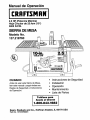
1
Owner's Manual
2.5 HP (Maximum
10" Inch Blade
5000 R.P.M.
Developed)
TABLE SAW
Model No.
137.218760_
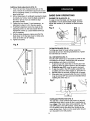
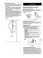
CAUTION:
•
•
•
•
•
•
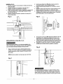
Before using this Table Saw,
read this manual and follow
all its Safety Rules and
Operating Instructions.
Customer
Help
Safety Instructions
Installation
Operation
Maintenance
Parts List
EspaSol
Line
1-800-843-1682
Sears,
Roebuck
Part No. 137218760001
and Co., Hoffman
Estates,
IL 60179
USA
SECTION
PAGE
Warranty ................................................................
Product Specifications
.....................................................
Safety Instructions
.........................................................
Accessories
and Attachments
...............................................
Tools needed for assembly
.................................................
Carton Contents ..........................................................
Know Your Table Saw ......................................................
Assembly and Adjustments
.................................................
Operation
..............................................................
Maintenance
............................................................
Troubleshooting
guide ....................................................
Parts ..................................................................
Making a push stick ......................................................
Espafiol ................................................................
2
2
3
6
6
6
8
9
14
18
19
20
27
31
FULL ONE YEAR WARRANTY
If this product fails due to a defect in material or workmanship within one year from the date of purchase, Sears
will repair it free of charge.
Contact a Sears Service Center for repair.
If this product is used for commercial or rental purposes, this warranty applies only for 90 days from the date of
purchase.
This warranty gives you specific legal rights, and you may also have other rights which vary from state to state.
Sears, Roebuck and Co., Dept. 817 WA, Hoffman Estates, IL 60179
MOTOR
Maximum developed HP .........
Volts ........................
Amperes .....................
Hertz .......................
2.5
120
13
60
RPM (no load) ................
Overload protection .............
5000
YES
SAW
Table
Blade
17 1/8" x 26"
10"
.......................
.......................
Maximum depth of cut at 90 ° .....
Maximum depth of cut at 45 ° .....
Maximum width of dado .........
Weight ......................
3"
2-1/2"
1/2"
40 Ibs.
To avoid electrical hazards, fire hazards, or damage to
the tool, use proper circuit protection.
Your table saw is wired at the factory for 120V operation.
Connect to a 120V, 15 AMP branch circuit and use a 15
AMP time delay fuse or circuit breaker. To avoid shock or
fire, replace power cord immediately if it is worn, cut or
damaged in any way.
GENERAL SAFETY INSTRUCTIONS
BEFORE
USING THE TABLE SAW
Safety is a combination of common sense, staying alert
and knowing how to use your table saw.
To avoid mistakes that could cause serious injury, do not
plug the table saw in until you have read and understood
the following:
1.
READ and become familiar with this entire instruction
manual. LEARN the tool's applications, limitations, and
possible hazards.
2.
KEEP GUARDS IN PLACE and in working order.
3.
REMOVE ADJUSTING KEYS AND WRENCHES.
Form the habit of checking to see that keys and
adjusting wrenches are removed from the tool before
turning ON.
4,
.
.
7.
KEEP WORK AREA CLEAN. Cluttered areas and
benches invite accidents.
DON'T USE IN A DANGEROUS ENVIRONMENT.
Don't use power tools in damp or wet locations, or
expose them to rain. Keep work area well lighted.
KEEP CHILDREN AWAY. All visitors should be kept at
a safe distance from the work area.
MAKE WORKSHOP KID PROOF with padlocks, master
switches, or by removing starter keys.
8.
DON'T FORCE THE TOOL. It will do the job better
and safer at the rate for which it was designed.
9.
USE THE RIGHT TOOL. Don't force tool or the
attachment to do a job for which it was not.designed.
10. USE PROPER EXTENSION CORD. Make sure your
extension cord is in good condition. When using an
extension cord, be sure to use one heavy enough to
carry the current your product will draw. An undersized
cord will cause a drop in line voltage resulting in loss
of power and overheating.The table on page 7 shows
the correct size to use depending on cord length and
nameplate ampere rating. If in doubt, use the next
heavier gauge. The smaller the gauge number, the
heavier the cord.
11. WEAR PROPER APPAREL. DO NOT wear loose
clothing, gloves, neckties, rings, bracelets, or other
jewelry which may getcaught in moving parts.
Nonslip footwear is recommended. Wear protective
hair covering to contain long hair.
12.
ALWAYS WEAR EYE
PROTECTION. Any table
saw can throw foreign
objects into the eyes which
could cause permanent eye
damage. ALWAYS wear
Safety Goggles (not glasses)
that comply with ANSI safety standard Z87.1.
Everyday eyeglasses have only impact-resistant
lenses. They ARE NOT safety glasses. Safety
Goggles are available at Sears. NOTE: Glasses or
goggles not in compliance with ANSI Z87.1 could
seriously hurt you when they break.
13. WEAR A FACE MASK OR DUST MASK.
Sawing operation produces dust.
14. SECURE WORK. Use clamps or a vise to hold work
when practical. It's safer than using your hand and it
frees both hands to operate tool.
15. DISCONNECT TOOLS before servicing, and when
changing accessories, such as blades, bits, cutters,
and the like.
16. REDUCE THE RISK OF UNINTENTIONAL STARTING.
Make sure the switch is in OFF position before
plugging in.
17. USE RECOMMENDED ACCESSORIES. Consult the
owner's manual for the recommended accessories.
The use of improper accessories may cause risk of
injury to persons.
18. NEVER STAND ON TOOL. Serious injury could occur
if the tool is tipped or if the cuttingtool is unintentionally
contacted.
19. CHECK FOR DAMAGED PARTS. Before further use of
the tool, a guard or other part that is damaged should
be carefully checked to determine that it will operate
properly and perform its intended function. Check for
alignment of moving parts, binding of moving parts,
breakage of parts, mounting,and any other conditions
that may affect its operation.A guard or other part that
is damaged should be properly repaired or replaced.
20. NEVER LEAVE TOOL RUNNING UNATTENDED.
TURN THE POWER OFF. Don't leave the tool until
it comes to a complete stop.
DON'T OVERREACH. Keep proper footing and
balance at all times.
MAINTAIN TOOLS WITH CARE. Keep tools sharp
and clean for best and safest performance. Follow
instructions for lubricating and changing accessories.
SAVE THESE INSTRUCTIONS
12. PROVIDE ADEQUATE SUPPORT to the rear and
sides of the saw table for wide or long workpieces.
23. DIRECTION OF FEED. Feed work into a blade or cutter
against the direction of rotation of the blade or cutter
only.
13. AVOID KICKBACKS (work thrown back towards
you) by keeping the blade sharp, keeping the rip
fence parallel to the saw blade, and by keeping the
spreader, anti-kickback pawls, and guard in place
and functioning. Do not release work before it is
pushed all the way past the saw blade. Do not rip
work that is twisted, warped, or does not have a
straight edge to guide along the fence.
24. WARNING: Dust generated from certain materials can
be injurious to your health. Always operate saw in well
ventilated areas and provide for proper dust removal.
SPECIFIC SAFETY INSTRUCTIONS
FOR THE TABLE SAW
,
2.
.
.
ALWAYS USE SAW BLADE GUARD spreader and
anti-kickback pawls for every operation for which
they can be used, including through-sawing.
Through-sawing operations are those in which the
blade cuts completely through the workpiece
when ripping or cross-cutting.
14. AVOID AWKWARD OPERATIONS and hand
positions where a sudden slip could cause your
hand to move into the cutting tool.
15. NEVER USE SOLVENTS to clean plastic parts.
Solvents could possibly dissolve or otherwise
damage the material. Only a soft damp cloth should
be used to clean plastic parts.
ALWAYS HOLD THE WORK FIRMLY against the
miter gauge or rip fence.
USE A PUSH STICK when required. Always use a
push stick for ripping narrow stock. Refer to ripping
applications in the instruction manual where the
push stick is covered in detail. See the push stick
pattern included in this Owner's Manual.
16. MOUNT your table saw before performing any
cutting operations. Refer to installation instructions.
17. NEVER CUT METALS or materials which may make
hazardous dust.
NEVER PERFORM ANY OPERATION
"FREE HAND", which means using your hands
only to support or guide the workpiece. Always
use either the fence or the miter gauge to position
and guide the work.
5.
NEVER STAND or have any part of your body
in line with the path of the saw blade. Keep your
hands out of the line of the saw blade.
6.
NEVER REACH behind or over the cutting tool
for any reason.
7.
REMOVE the rip fence when cross-cutting.
8.
DO NOT USE molding head set with this saw.
9.
FEED WORK INTO THE BLADE against the
direction of rotation only.
18. ALWAYS USE IN A WELL VENTILATED AREA.
Remove sawdust frequently. Clean out sawdust from
the interior of the saw to prevent a potential fire
hazard.
19. NEVER LEAVE THE TOOL running unattended.
Don't leave the tool until it comes to a complete stop.
20. For proper operation follow the instructions of this
owner's manual titled "SAW MOUNTED TO WORK
SURFACES." Failure to provide sawdust fall-through
and removal hole will allow sawdust to build up in
the motor area, which may result in a fire hazard or
cause motor damage.
ELECTRICAL
REQUIREMENTS
POWER SUPPLY AND MOTOR
SPECIFICATIONS
10. NEVER use the fence as a cut-off gauge when
cross-cutting.
rvA,W_t"_II_[¢
11. NEVER ATTEMPT TO FREE A STALLED SAW
BLADE without first turning the saw OFF. Turn
power switch OFF immediately to prevent motor
damage.
To avoid electrical hazards, fire hazards, or damage to
the tool, use proper circuit protection. Use a separate
electrical circuit for your tools.Your saw is wired at the
factory for 120V operation. Connect to a 120V, 15 Amp
circuit and use a 15 Amp time delay fuse or circuit
breaker. To avoid shock or fire, if power cord is worn or
cut, or damaged in any way, have it replaced
immediately.
SAVE THESE INSTRUCTIONS
4
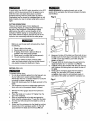
GROUNDING
INSTRUCTIONS
Fig. A
3-Prong Plug
IN THE EVENT OF A MALFUNCTION OR BREAKDOWN,
grounding provides a path of least resistance for electric
current and reduces the risk of electric shock. This tool
is equipped with an electric cord that has an equipment
grounding conductor and a grounding plug. The plug
MUST be plugged into a matching receptacle that is
properly installed and grounded in accordance with ALL
local codes and ordinances.
_
DO NOT MODIFY THE PLUG PROVIDED. If it will not
fit the receptacle, have the proper receptacle installed
by a qualified electrician.
pr_i_el;d_go_iing
e
Fig. B
Grounding Lug
IMPROPER CONNECTION of the equipment grounding
conductor can result in risk of electric shock. The
conductor with the green insulation (with or without
yellow stripes) is the equipment grounding conductor. If
repair or replacement of the electric cord or plug is
necessary, DO NOT connect the equipment grounding
conductor to a live terminal.
_ Make Sure This
is Connected to a
Known Ground
"_ 2-Prong
Receptacle
CHECK with a qualified electrician or service person if
you do not completely understand the grounding
instructions,or if you are not sure the tool is properly
grounded.
GUIDELINES
FOR EXTENSION
CORDS
USE ONLY 3-wire extension cords that have 3-prong
grounding plugs and 3-pole receptacles that accept
the tool's plug. Repair or replace damaged or worn
cord immediately.
USE A SEPARATE ELECTRICAL CIRCUIT for your
tools. This circuit must not be less than #12 wire and
should be protected with a 15 Amp time delay fuse.
Before connecting the motor to the power line, make
sure the switch is in the OFF position and the electric
current is rated the same as the current stamped on the
motor nameplate. Running at a lower voltage will
damage the motor.
USE PROPER EXTENSION CORD. Make sure your
extension cord is in good condition.When using an
extension cord, be sure to use one heavy enough to carry
the current your productwill draw.An undersized cord will
result in a drop in line voltage and in loss of power which
will cause the tool to overheat. The table below shows the
correct size to use depending on cord length and
nameplate ampere rating. If in doubt, use the next heavier
gauge. The smaller the gauge number, the heavier the
cord.
This tool is intended for use on a circuit that has a
receptacle like the one illustratedin FIGURE A. FIGURE A
shows a 3-prong electrical plug and receptacle that has a
grounding conductor. If a properly grounded receptacle is
not available, an adapter (FIGURE B) can be used to
temporarily connect this plug to a 2-contact ungrounded
receptacle. The temporary adapter should be used only
until a properly grounded receptacle can be installed by
a qualified technician.The adapter (FIGURE B) has a
rigid lug extending from it that MUST be connected to a
permanent earth ground, such as a properly grounded
receptacle box. The Canadian Electrical Code prohibits
the use of adapters.
Be sure your extension cord is properly wired and in
good condition.Always replace a damaged extension cord
or have it repaired by a qualified person before using it.
Protect your extension cords from sharp objects,
excessive heat and damp or wet areas.
r_ k_v/_[-.._ll_[_
CAUTION: In all cases, make certain the receptacle is
properly grounded. If you are not sure have a qualified
electrician check the receptacle.
This tool must be grounded while in use to protect the
operator from electrical shock.
IITAII_IILVILIJ_I[_
LS[O]Zl I_['4Btl::l_[,,,,']
[0]_1 [o,][o_,]=]Lm,3_]
[_]
(when
rv_l,VlVl_,_
--1_,II_ [e
Ampere
This table saw is for indoor use only. Do not expose to
rain or use in damp locations.
Rating
120 volts
length
only)
of cord
in feet
more than
not more than
25'
50'
100'
1 SO'
0
6
18
16
16
14
6
10
18
16
14
12
10
12
16
16
14
12
16
14
12
Not
SAVE THESE INSTRUCTIONS
5
using
Total
12
Recommended
RECOMMENDED
ACCESSORIES
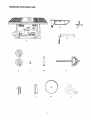
UNPACKING AND CHECKING CONTENTS
Separate all parts from packing material. Check each one
with the illustration on the next page and the table of
loose parts to make certain all items are accounted for,
before discarding any packing material.
Visit your Sears Hardware Department or see the
Craftsman Power and Hand Tools Catalog to purchase
recommended accessories for this power tool.
To avoid the risk of personal injury:
•
Do not use adjustable (wobble) type dadoes or
carbide tipped dado blades, maximum dado width
is 1/2".
•
•
•
To avoid personal injurty, if any parts are missing or
damaged, do not attempt to assemble the table saw, plug
in the power cord, or turn the switch on until the missing
or damaged part is obtained and is installed correctly.
Do not use a dado with a diameter larger than 6".
Do not use molding head set with this saw.
Do not modify this power tool or use accessories not
recommended by Sears.
TABLE OF LOOSE PARTS
ITEM
DESCRIPTION
A.
B.
C.
Table saw assembly
Blade guard and splitter
Bolt, flat washer, toothed washer,
oval washer
Rip fence and handle
Handwheels
Dome nuts
Dado insert
Miter gauge
Hex key
Blade wrenches
Blade
Push shoe
D.
E.
E
G.
H.
I.
J.
K.
L.
TOOLS NEEDED
Medium screwdriver
QUANTITY
1
1
1 each
1
2
2
1
1
2
2
1
1
Adjustable wrench
NOTE: To make assembly easier, keep contents of box
together. Apply a coat of automobile wax to the table.
Wipe all parts thoroughly with a clean dry cloth. This will
reduce friction when pushing the workpiece.
#2 Phillipsscrewdriver
I I Ill
I till
Straight edge
I I ]
t'_'_'°i'_:_'_i4"_i_
", , , , , ,
Combination square
6
UNPACKING
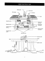
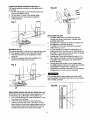
YOUR TABLE SAW:
C
A
e
e
1
H
G
K
L
Blade guard
.=insert
Miter gauge
Rip fence
Table
/
Blade tilt pointer
l in.
TABLE
SAW
Blade bevel
lock knob
Blade tilt scale
Blade tilting
handwheel
ON/OFF switch
with key
Blade elevation
handwheel
Overload reset
switch
Mounting holes
Kickback pawls
Splitter
Blade
.J
€ plitter bracket
_nches
Mounting hole
8
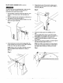
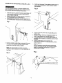
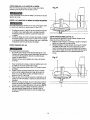
SAW MOUNTED TO WORK SURFACES (FIG. A)
1. The saw must be properly secured to a sturdy
workbench using the four mounting holes at the base
of the saw.
2. The surface of the table where the saw is to be
mounted must have a hole large enough to facilitate
sawdust fall-through and removal.
3. Square the saw on the mounting surface and mark
the location of the four 3/8" mounting holes (1).
4. Drill 3/8" holes into the mounting surface.
5. Mark an 11" square (2) centered between the four
mounting holes (1).
6. Cut out and remove the square.
7. This opening will allow sawdust to fall through
the saw base.
8.
9.
Fig. B
Place the saw on the work surface, and align the
mounting holes of the saw with those drilled through
the surface.
Fasten the saw to the work surface.
Fig. A
1
l
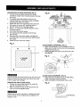
BLADE RAISING HANDWHEEL (FIG. C)
1. Attach the handwheel (1) to the elevation screw (2).
Make sure the slots (3) in the hub of the handwheel
engage with the pins (4).
2. Attach and tighten the dome nut (5) at the end of the
shaft (Fig. D).
2
Fig. C
3
2
4
1
P_Eig'Zld_l_€
BLADE TILTING HANDWHEEL (FIG. D)
1. Attach the other handwheel (6) to the blade tilting
screw in the same manner as above.
2. Attach and tighten the handwheel dome nut (5).
Failure to provide the sawdust fall-through hole will cause
sawdust to build up in the motor area, which may result
in fire or cause motor damage.
KEEPING THE AREA CLEAN (FIG. B)
1. Sawdust and wood chips that fall from under the
saw will accumulate on the floor.
2. Make it a practice to pick up and discard this dust
when you have completed cutting.
Fig. D
Always keep your work area clean, uncluttered and well
lit. Do not work on floor surfaces that are slippery from
sawdust or wax.
9
RIP FENCE (FIG. E)
1. Thread the fence handle (1) into the cam hole (2)
until tight.
2. Lift upward on the rip fence handle (1) so that the
holding clamp (3) is fully extended.
3. Place the rip fence on the saw table and engage
the holding clamp (3) to the table rear. Lower the
front end onto the front rail (4).
4. Push down on the fence handle (1) to lock.
2.
Raise the blade arbor (4) (FIG. G) to the maximum
height by turning the blade-raising handwheel
counterclockwise.
3.
4.
Remove the arbor nut (5) and flange (6), remove blade.
Install the new saw blade onto the arbor with the
blade teeth pointing toward the front of the saw.
Install the flange (6) against the blade and thread the
arbor nut (5) as far as possible by hand. Ensure that
the blade is flush against the inner side of the blade
flange.
5.
Fig. E
Fig. G
5
I
I
I
I
I
I
I
I
I
I
4
6.
CHANGING THE BLADE (FIG. F, G, H)
7.
8.
To avoid injury from an accidental start, make sure the
switch is in the OFF position and the plug is not
connected to the power source outlet.
.
To tighten the arbor nut (5) (FIG. H) use the open-end
wrench (7) and align the wrench jaws on the flats of
the blade arbor to keep the arbor from turning.
Place the box-end wrench (8) on the arbor nut (5),
and turn clockwise (to the rear of the saw table.)
Replace the blade insert in the table recess, insert
screws through the front and rear holes and tighten.
Fig. H
Remove the table insert (1) by unscrewing the two
screws (2, 3). Be careful not to lose the rubber
washer that is on the back screw (3) beneath the
table insert.
7
8
5
NOTE: The back screw is longer than the
front screw.
Fig. F
1
_3
To avoid injury from a thrown workpiece, blade
parts, or blade contact, never operate saw without
the proper insert in place. Use the saw blade
insert when sawing. Use the dado head insert
when using a dado.
2
10
BLADE GUARD ASSEMBLY (FIG. I, J, K, L)
.
To avoid injury from an accidental start, make sure the
switch is in the OFF position and the plug is not
connected to the power source outlet.
1.
Set the blade to maximum height and the tilt to zero
degrees on the bevel scale. Lock the blade lock
knob.
2.
Place the external tooth Iockwasher (2) followed by a
flat washer (3) onto the long bolt (1).
Insert this bolt through the splitter bracket (4) on the
back of the guard assembly.
3.
Check that the nuts (7) that hold the blade guard
assembly (8) to the bracket (4) are tight. Tighten if
necessary. (FIG. K)
Fig. K
Fig. I
6.
7.
8.
3
2
9.
.
Position the blade guard arm (9) (FIG. L) to the
rear.
Using a straight edge, check to see that the blade
guard splitter (10) is aligned with the saw blade (11).
If straightening adjustment is necessary, the
splitter (10) can be shifted to the left or to the right,
and rotated.
When you are certain the splitter is properly aligned
with the saw blade, tighten the bolt (1).
Place washer (6) on to the pivot rod (5). Insert the
guard assembly into the pivot rod (5) (FIG. J and K)
at the rear of the saw table and tighten.
NOTE: The splitter must always be correctly aligned
so that the cut workpiece will pass on either side of
the splitter without binding or twisting to the side.
NOTE: Blade guard and splitter assembly removed
from the splitter bracket illustration for clarity, in
(FIG. J).
Fig. L
Fig. J
10
11
I
MITER GAUGE ADJUSTMENT (FIG. M)
1. Make sure that the miter gauge will slide freely through
both table grooves.
2. Loosen the lock knob (1). Set the pointer (2) to the 90 °
mark on the scale.
3. Make a 90° cut in a piece of scrap wood. Check cut
piece to see if it was cut at 90 °. If it is not, continue to
adjust the miter gauge body (3) until the wood piece
is cut at 90 °. Refer to OPERATION section for cutting
instructions.
Fig. N
,,
Fig. M
8675
2_
° o
1_3
2
ADJUSTMENT
INSTRUCTIONS
RIP FENCE ADJUSTMENT
(FIG. N)
To avoid injury from an accidental start, make sure
the switch is in the OFF position and the plug is
not connected to the power source outlet.
1.
2.
3.
4.
5.
The fence (1) is moved by lifting up on the handle (2)
and sliding the fence to the desired location. Pushing
down on the handle locks the fence in position.
Position the fence on the right side of the table, and
along one edge of the miter gauge grooves.
Lock the fence handle. The fence should be parallel
with the miter gauge groove.
If adjustment is needed to make the fence parallel to
the groove, do the following:
• Loosenthe two screws (3) and lift up on the handle (2).
• Hold the fence bracket (4) firmly against the front
of the saw table. Move the far end of the fence
until it is parallel with the miter gauge groove.
• Tighten both screws and push the handle to lock.
If fence is loose when the handle is in the locked
(downward) position, do the following:
• Move the handle (2) upward and turn the adjusting
screw (5) clockwise until the rear clamp is snug.
Do not turn the adjusting screw more than 1/4
turn at a time.
• Over-tightening the adjusting screw will cause
the fence to come out of alignment.
....
RIP FENCE INDICATOR ADJUSTMENT (FIG. N)
1. The rip fence indicator (6) points to the
measurement scale (8). The scale shows the
distance from the side of the fence, to the nearest
side of the blade.
2. Measure the actual distance with a rule. If there is a
difference between the measurement and the
indicator, adjust the indicator (6).
3. Loosen the screw (7) and slide the indicator to the
correct measurement on the scale. Tighten screw
and remeasure with the rule.
To avoid injury from an accidental start, make sure the
switch is in the OFF position and the plug is not
connected to the power source outlet.
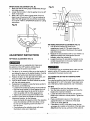
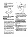
ADJUSTING THE 90 ° AND 45 ° POSITIVE STOPS
(FIG. O, P)
Your saw has positive stops that will quickly position the
saw blade at 90 ° or 45 ° to the table. These stops were
set at the factory. Make adjustments only if necessary.
90 ° Stop
1. Disconnect the saw from the power source.
2. Turn the blade elevation handwheel and raise the
blade to the maximum elevation.
3. Loosen the blade bevel lock knob and move the
blade to the maximum vertical position. Tighten the
lock knob.
4. Place a combination square on the table and
against the blade (1) to determine if the blade
is 90 ° to the table. (FIG. O)
5. If the blade is not 90° to the table, loosen the two
set screws (4), located on the bottom of the table saw,
(FIG. P) with the hex key, and back off the collar (5).
12
:
6.
Loosen the bevel lock knob. Turn the blade tilting
handwheel to move the blade until it is 90° to the
table.
BLADE PARALLEL TO MITER GAUGE
GROOVE (FIG. Q, R)
7.
Adjust the collar (5) so it contacts the bracket (3)
when the blade is 90 ° to the table. Tighten the
two set screws (4).
This adjustment was made at the factory, but it should
be rechecked and adjusted if necessary.
_e
Fig. O
90 °
45 °
To prevent personal injury:
•
Always disconnect plug from the power source when
making any adjustments.
•
This adjustment must be correct or kickback could
result and accurate cuts cannot be made.
Initial adjustment (FIG. Q)
1.
2.
3.
4.
450 Stop
1. With the blade in the upright 90 ° position, loosen the
bevel lock knob. Turn the blade tilting handwheel and
move the blade to the 45 ° position as far as it will go.
2. Place the combination square on the table as shown
in (FIG. O) to check if the blade is 45 ° to the table.
3. If the blade is not 45 ° to the table, loosen the two set
screws (4) located under the table saw (FIG. P) with
a 3 mm hex key, and back off the collar (5).
4. Loosen the bevel lock knob; turn the tilting
handwheel to move the blade until it is 45 ° to the
table.
5. Adjust the collar (5) so it contacts the bracket (3)
when the blade is 45 °. Tighten set screws (4).
5.
6.
7.
8.
9.
Remove the yellow switch key and unplug
the saw.
Move the blade guard out of the way.
Raise the blade to the highest position and set at
the 0° angle (90 ° straight up).
Select and mark, with a felt tip marker, a blade
tooth having a "right set".
Place the combination square base (1) into the
right side miter gauge groove (2). (FIG. Q)
Adjust the rule so it touches the front marked tooth
and lock the ruler so it holds its position in the
square assembly.
Rotate the blade bringing the marked tooth to the
rear and about 1/2 inch above the table.
Carefully slide the combination square to the rear
until the ruler touches the marked tooth.
If the ruler touches the marked tooth at the front and
rear positions, no adjustment is needed at this time.
If not, perform adjustment procedure described in
next section.
Fig. O
BLADE TILT POINTER
1. When the blade is positioned at 90 °, adjust the
blade tilt pointer to read 0 ° on the scale.
2. Loosen the holding screw, position pointer over 0°
and tighten screw.
NOTE: Make a trial cut on scrap wood when making
critical cuts. Measure for exactness.
Fig. P
345
13
Additional blade adjustments (FIG. R)
1. If the front and rear measurements are not the
same, remove the combination square and loosen
the four adjusting screws (1) on the top of the table
about a half turn.
2. With a folded piece of cardboard covering the blade
to protect your hands, move the blade carefully to
the left or right as much as needed to align
the blade correctly.
3. Tighten the four screws (1) and remeasure, as
described in steps 4 to 9 in the prior section.
4. If sufficient adjustment cannot be made by the
adjusting screws (1), then also loosen the two
adjustment screws (2). Loosen these screws (2)
only if necessary.
5. Recheck blade clearance making sure that the
blade does not hit the table insert or other parts
when at the 90° and 45 ° settings.
6. Tighten all screws.
BASIC SAW OPERATIONS
RAISING THE BLADE (FIG. S)
To raise or lower the blade, turn the blade elevation
handwheel (1) to the desired blade height, and then
tighten lock handle (2) to maintain the desired blade
angle.
Fig. S
3
Fig. R
TILTINGTHE BLADE (FIG. S)
To tilt the saw blade for bevel cutting, loosen the
lock knob (2) and turn the tilting handwheel (3). Tighten
the lock knob (2) to secure.
2
ON / OFF SWITCH (FIG. T)
The ON / OFF switch has a removable key. With the key
removed from the switch, unauthorized and hazardous
use by children and others is minimized.
1. To turn the saw ON, insert key (1) into the slot in the
switch (2). Move the switch upward to the ON position.
2. To turn the saw OFF, move the switch downward.
3. To lock the switch in the OFF position, grasp the end
(or yellow part) of the switch toggle (1), and pull it out.
4. With the switchkey removed,the switchwillnot operate.
5. If the switch key is removed while the saw is running,
it can be turned OFF but cannot be restarted without
inserting the switch key (1).
Fig.T
• RESET
3
OVERLOAD PROTECTION (FIG. T)
This saw has a reset overload relay button (3) that will
restart the motor after it shuts off due to overloading or
low voltage. If the motor stops during operation, turn the
ON/OFF switch to the OFF position. Unplug the saw
from its power source. Wait about five minutes for the
motor to cool down. Push in on the reset button (3) and
turn the switch to the ON position.
14
r_Lv_ d2_e
To avoid injury, the ON/OFF switch should be in the OFF
position and the plug removed from the power source
while the motor cool down takes place, to prevent
accidental starting when the reset button is pushed.
Overheating may be caused by misaligned parts or dull
blade. Inspect your saw for proper setup before using it
again.
AVOID KICKBACK by pushing forward only on that
section of the workpiece that will pass between the blade
and the fence.
Fig. U
CUTTING OPERATIONS
There are two basic types of cuts: ripping and
crosscutting. Ripping is cutting along the length and
the grain of the workpiece. Crosscutting is cutting
either across the width or across the grain of the
workpiece. Neither ripping nor crosscutting may be
done safely freehand. Ripping requires the use of the
rip fence, and crosscutting requires the miter gauge.
Before you use the saw each and every time, check
the following:
1. Blade is tight on the arbor.
2. Bevel angle lock knob is tight.
3. If ripping, fence knob is tight and fence is
parallel to the miter gauge grooves.
4. Blade guard is in place and working properly.
5. You are wearing safety glasses.
6.
The failure to adhere to these common safety
rules, and those printed in the front of this manual,
can greatly increase the likelihood of injury.
7.
8.
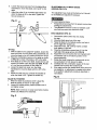
RIPPING (FIG. U, V)
9.
To prevent serious injury:
•
Do not allow familiarity gained from the frequent use
of your table saw to cause careless mistakes.
Remember that even a careless fraction of a second
is enough to cause a severe injury.
•
Keep both hands away from the blade and path of the
blade.
•
The workpiece must have a straight edge against the
fence and must not be warped, twisted, or bowed.
1.
2.
3.
4.
5.
Keep your thumbs off the table top. When both of your
thumbs touch the front edge of the table (2), finish the
cut with a push stick. Make a push stick using the
pattern on page 27.
The push stick (3) should always be used when the
ripped workpiece is 2" or narrower (1). (FIG. V)
Continue pushing the workpiece with the push stick (3)
until it passes the blade guard and clears the rear of
the t_le.
Never pull the workpiece back when the blade is
turning. Turn the switch OFF. When the blade
completely stops raise the anti-kickback pawls on
each side of the splitter and slide the workpiece out.
Fig. V
Remove the miter gauge. Secure the rip fence to
the table.
Raise the blade so it is about 1/8" higher than the
top of the workpiece.
Place the workpiece flat on the table and against the
fence. Keep the workpiece about 1" away from the blade.
Turn the saw ON and wait for the blade to come up
to speed.
Slowly feed the workpiece into the blade by pushing
forward only on the workpiece section (1) that will
pass between the blade and the fence. (FIG. U)
2
1
15
BEVEL RIPPING
This cut is the same as ripping except the blade bevel
angle is set to an angle other than 0 °.
Fig. W
3
2
Cut only with the workpiece and the fence on the right
side of the blade.
RIPPING SMALL PIECES
rv_kvAvl__1
_|_II_€
Avoid injury from blade contact. Never make through-saw
cuts narrower than 1/2" wide.
,
2.
It is unsafe to rip small pieces. Instead, rip a larger
piece to obtain the size of the desired piece.
When a small width is to be ripped and your hand
cannot be safely put between the blade and the
rip fence, use one or more push sticks to move
the workpiece.
CROSSCUTTING
BEVEL CROSSCUTTING (FIG. X)
This cutting operation is the same as crosscutting except
the blade is at bevel angle other than 0 °.
1. Adjust the blade (1) to the desired angle, and tighten
the blade bevel lock knob.
2. Always work to the left side of the blade. The miter
gauge (3) must be in the left side groove (2). It
cannot be used in the right side groove unless the
miter angle is very sharp, as it will interfere with the
blade guard.
(FIG. W)
To prevent serious injury:
•
Do not allow familiarity gained from the frequent use
of your table saw to cause careless mistakes.
Remember that even a careless fraction of a second
is enough to cause a severe injury.
•
Keep both hands away from the blade and path of the
blade.
1.
2.
3.
4.
5.
6.
Fig. X
1
Remove the rip fence and place the miter gauge in
the left side groove.
Adjust the blade height so it is 1/8" higher than the
top of the workpiece.
Hold the workpiece firmly against the miter gauge
with the blade path in line with the desired cut
location. Move the workpiece to one inch distance
from the blade.
Start the saw and wait for the blade (1) to come up to
full speed.
Keep the workpiece (2) against the face of the miter
gauge (3) and flat against the face of the gauge and
flat against the table. Then slowly push the
workpiece through the blade (FIG. W).
Do not try to pull the workpiece back with the blade
turning. Turn the switch OFF, and carefully slide the
workpiece out when the blade is completely stopped.
\Of
n
2
16
COMPOUND MITER CROSSCUTTING (FIG.Y)
This sawing operation combines a miter angle with a
bevel angle.
1. Set the miter gauge (3) to the desired angle. Use
only the left side groove (2).
2. Set the blade (1) bevel to the desired angle.
3. Carefully push the miter gauge to begin the
cutting operation.
Fig. AA
... _3
F
2
1
Fig.Y
/_
DADO CUTS (FIG. BB)
1. The dado table insert is included with this saw.
Remove saw blade, blade guard, installed dado,
and dado table insert.
2. Instructions for operating the dado are packed with
the separately purchased dado set.
3. The arbor (1) on this saw restricts the maximum
width of the cut to 1/2".
4. It is not necessary to install the outside flange (2)
before screwing on the arbor nut (3). Make sure that
the arbor nut (3) is tight, and that at least one thread
of the arbor sticks out past the nut.
5. Use only the 6" dado set and keep the width 1/2" or
less. It will be necessary to remove the blade guard
and splitter when using dado. Use caution when
dado is operating.
6. Use only the correct number of round outside blades
and inside chippers as shown in the dado set's instruction
manual. Blade or chipper must not exceed 1/2".
7. Check saw to ensure that the dado will not strike the
housing, insert, or motor when in operation.
MITERING (FIG. Z)
This sawing operation is the same as crosscutting except
the miter gauge is locked at an angle other than 90 °,
1. Hold the workpiece (2) firmly against the miter
gauge (3),
2. Feed the workpiece slowly into the blade (1) to
prevent the workpiece from moving.
Fig. Z
2
1
/
I
rt_kv_v_l_[e
For your own safety, always replace the blade, blade
guard assembly, and blade insert when you are finished
with the dado operation.
Fig. BB
5r
USING WOOD FACING ON THE RIP FENCE (FIG. AA)
When performing some special cutting operations, add
a wood facing (1) to either side of the rip fence (2):
1. Use a smooth straight 3/4" thick wood board (1) that
is as long as the rip fence.
2. Attach the wood facing to the fence with wood
screws (3) through the holes in the fence. A wood
fence should be used when ripping material such as
thin paneling to prevent the material from catching
between the bottom of the fence and the table.
17
I
MAINTAINING
YOUR TABLE SAW
Fig. CC
GENERAL MAINTENANCE
For your own safety, turn the switch OFF and remove the
switch key. Remove the plug from the power source
outlet before maintaining or lubricating your saw.
1.
2.
3.
4.
Clean out all sawdust that has accumulated inside
the saw cabinet and the motor.
Polish the saw table with an automotive wax to keep
it clean and to make it easier to slide the workpiece.
Clean cutting blades with pitch and gum remover.
A worn, cut, or damaged power cord should be
replaced immediately.
All electrical or mechanical repairs should be attempted
only by a trained repair technician. Contact the nearest
Sears Service Center for service. Use only identical
replacement parts. Any other parts may create a hazard.
5.
.
/
NOTE: Certain cleaning chemicals can damage
plastic parts.
Place a small amount of dry lubricant such
or silicon on screw rod (1) at thrust washer
oil threads of screw rods (1). Screw rod (1)
kept clean and free of sawdust, gum, pitch,
contaminants for smooth operation.
Avoid use of the following cleaningchemicals or
solvents: gasoline, carbon tetrachloride,chlorinated
solvents, ammonia and household detergents
containing ammonia.
If excessive looseness is observed in any other part of
the blade raising mechanism or tilting mechanism, take
the complete unit to a Sears Service Center.
Use liquid dish washing detergent and water to
clean all plastic parts.
BLADE RAISING AND TILTING MECHANISM (FIG. CC)
After each five hours of operation, the blade raising
mechanism and tilting mechanism should be checked for
looseness, binding, or other abnormalities. With the saw
disconnected from the power source, turn the saw
upside down. and alternately pull upward and downward
on the motor unit. Observe any movement of the motor
mounting mechanism. Looseness or play in the blade
raising screw (1) should be adjusted as follows:
1.
2.
3.
as graphite
(5). Do not
must be
and other
LUBRICATION
All motor bearings are permanently lubricated at the
factory and require no additional lubrication.
On all mechanical parts of your table saw where a
pivot or threaded rod are present, lubricate using
graphite or silicone. These dry lubricants will not
hold sawdust as would oil or grease.
Using a wrench, loosen nut (2).
Adjust nut (3) until it is finger-tight against the
bracket (4), then back off the nut (3) 1/6 turn.
Tighten nut (2) with the wrench, while holding nut (3)
in place. Maximum allowable play of screw rod (1)
is 4 mm.
18
TROUBLESHOOTING
GUIDE
To avoid injury from an accidental start, turn the switch OFF and always remove the plug from the power source
before making any adjustments.
= Consult your local Sears Service Center if for any reason the motor will not run.
SYMPTOM
POSSIBLE
CAUSES
CORRECTIVE
ACTION
Saw will not start.
1. Saw not plugged in.
2. Fuse blown or circuit breaker tripped.
3. Cord damaged.
1.
2.
3.
Plug in saw.
Replace fuse or reset circuit breaker.
Have cord replaced by a Sears
Service Center.
Does not make
accurate 45 °and
90 ° rip cuts.
1. Positive stop not adjusted correctly.
1.
2. Blade tilt pointer not set accurately.
2.
Check blade with square and adjust
positive stop.
Check blade with square and adjust
pointer to zero.
Material pinches blade
when ripping.
1. Rip fence not aligned with blade.
2. Warped wood, edge against
fence is not straight.
1. Check and adjust rip fence.
2. Select another piece of wood.
Material binds on splitter.
1. Splitter not aligned correctly
with blade.
1.
Saw makes
unsatisfactory cuts.
1. Dull blade.
2. Blade mounted backwards.
3. Gum or pitch on blade,
1. Replace blade.
2. Turn blade around.
3. Remove blade and clean with
turpentine and coarse steel wool.
4. Change the blade.
5. Clean table with turpentine
and steel wool.
4. Incorrect blade for work being done.
5. Gum or pitch on table
causing erratic feed.
Check and align splitter with blade.
Material kicked back
from blade.
1.
2.
3,
4.
5.
6.
Rip fence out of alignment.
Splitter not aligned with blade.
Feeding stock without rip fence.
Splitter not in place.
Dull blade.
The operator letting go of material
before it is past saw blade.
7. Miter angle lock knob is not tight.
1. Align rip fence with miter gauge slot.
2. Align splitter with blade.
3. Install and use rip fence.
4. Install and use splitter (with guard).
5. Replace blade.
6. Push material all the way past saw
blade before releasing work.
7. Tighten knob.
Blade does not
raise or tilt freely.
1. Sawdust and dirt in raising
and tilting mechanisms.
1.
Brush or blow out loose dust and dirt.
Blade does not
come up to speed.
1. Extension cord too light
or too long.
2. Low house voltage,
1.
Replace with adequate size cord.
2.
Contact your electric company.
1. Saw not mounted securely to
workbench.
2. Bench on uneven floor.
1.
Tighten all mounting hardware.
2.
3. Damaged saw blade.
3.
Reposition on flat level surface.
Fasten to floor if necessary,
Replace blade.
1. Miter gauge out of adjustment.
1.
Adjust miter gauge.
Machine vibrates
excessively.
Does not make accurate
45 ° and 90 ° cross cuts.
19
CRAFTSMAN
10" TABLE SAW
MODEL
NO. 137.218760
_€
When servicing use only CRAFTSMAN replacement parts. Use of any other parts may create a HAZARD or cause
product damage. Any attempt to repair or replace electrical parts on this Table Saw may create a HAZARD unless
repair is done by a qualified service technician. Repair service is available at your nearest Sears Service Center.
Always order by PART NUMBER, not by key number
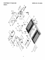
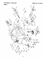
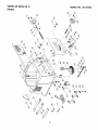
PARTS LIST FOR FIGURE A
Key No.
PART NUMBER
Description
Size
1
2
3
4
5
6
7
8
9
10
2615 BZDD50
2501MZDN06
14912301
2705FZD106
2690MZD514
14912205
2570DBN606
14913101
14913201
14913301
Hex hd. bolt
Flat washer
Supporting arm
Hex nut
Rivet
Blade .auard
Sel[-Ioc'_ingrin_!
_JcK DaCKpawl
Bushing
Roll pin
M6 x 1.0-40
6 x 13-1
11
12
13
14
15
14912801
14912904
2570DBN606
2536MBE607
14913401
GuadS
DaCrerbracket
Self-locking ring
Spring pin
Spring
..............................
17
18
19
20
21
22
23
24
25
26
27
28
29
30
M6 x 1.0 T=6
6-8
SPN-6
SPN-6
4-22
Qty
1
1
,1
1
2
1
2
2
2
1
21
2
1
1
......................................
Fl'ex" l':"l ............................................................
off
.................................
.....
14915101
2601BZDA47
2504MZC006
2501NZDN 16
1420500 ]
2701FBD106
14914901
2604BBLA42
2636BZDBA9
2801ABRGO 1
2621BZDA18
14903101
2621BZDA18
2636BZDB48
Wcirning label
Hex. hd.bolt
Toothed washer
Flat washer
.Splitterbracket
Hex. nut
Washer
Screw
Screw
Rubber washer
.Cap hd. screw
Insert
Cap. hd. screw
Cr. re. count hd. screw
M6 x 1.0-50
6
1/4 x 3/4-1/64
M6 x 1.0 T--5
D= 18
M6 x 1.0-25
M6 x 1.0-50
6.1
M5 x 0.8-12
M5 x 0.8-12
M6 x 1.0-55
1
1
1
1
1
2
2
3
3
1
1
1
1
10
................................ ............................................
?a'l Ye
..............................................................................................
i ......
32
33
34
35
36
37
38
39
40
41
42
:43
44
45
2668BEDA43
2668BEDA44
14902904
14910006
14910102
14914701
14910204
18611101
2501MZDN06
2504MZC006
2601BZDA40
14910502
18623801
2501MBDN28
Rd. hd.screw
Cr. re. count hd. screw
Scale
Fence
Locking rod
Cup
Rear clamp
Spring
Flat washer
Toothed washer
Hex hd. bolt
Front block
Spring
Frat washer
M6 x 1.0-30
M6 x 1.0-35
6 x 13-1
6
M6 x 1.0-16
10 x 16-1
1
1
1
1
1
1
1
1
2
2
2
1
1
.1
............................... .............................................
uicl uc ........................................................................................
i ......
47
48
49
50A
51
52
53
54
55
56
57
14002601
2701FZD113
18622201
14911005A1
2536MBE616
2536MBE608
14910701
2668BZDA06
14914802
14912205 B2
1491006B 1
Handle
Hex nut
M8 x 1.25 T=6.5
Eccentric
Front clamp
Spring pin
6-25
Spring pin
4-24
Pointer
Cap,hd. screw
M4 x 0.7-6
mracket tilt
Blade Guard Assembly- includes key # 1-15
Rip Fence Assembly - {ncludes key #35-54
_0
1
1
1
1
1
1
1
1
1
1
1
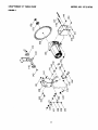
CRAFTSMAN
10" TABLE SAW
MODEL NO. 137.218760
FIGURE A
A
/
/
!
\
21
/
cO
\
\
\
CRAFTSMAN
10" TABLE SAW
MODEL
NO. 137.218760
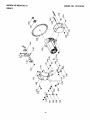
PARTS LIST FOR FIGURE B
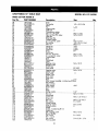
Key No.
PART NUMBER
Description
58
59
60
61
62
63
64
65
66
67
68
69
70
71
72
14911602
2501NZDN 16
14911402
14608001
14911802
29835L5006
14523301
2603BBLA38
2608BBLA32
14911707
14905801A 1
2504MZC004
2668BZDA09
2501NZDN16
2709FZDA02
Knob
Flat washer
Head
Pin
Ang!e pointer
_teel ball
Compression spring
Hex. soc. set screw
Hex. soc.truss Hd. screw
Sheet bar
Retaining chip
Toothed wasBer
Cr. re. pan hd. screw
Flat washer
Hex. nut
74
75
76
77
78
79
80
81
82
83
84
85
86
87
Size
1/4 x 3/4-1/64
L--20
5
M6 x 1.0-10
M5 x 0.8-10
4
M4 x 0.7-12
1/4 x 3/4 x 1/64
M6 x 1.0
Qty
1
1
1
1
1
1
1
1
2
1
1
2
2
4
4
.............................. ......................................
................................................................
.......................................
.....
2536MBE629
14936001
2570BBN209
14936501
2603BBLA36
2668BBDA39
14936701
14900111
14937102
14900391
2651PHD K 12
2853U55501
14902302
2801 DBHA04
Spring pin
Screw Bar
E-ring
Parrie ring
Hex soc. set screw
Cr. re. pan hd. screw
Caution label
Base
Handwheel
Label
Tapp,ing screw
Breaker switch
Switch box
Strain relief
3-14
L=309
E-9
M6 x 1.0-6
M6 x 1.0-12
M4 x 18,-10
RC-1632
1
1
2
2
4
4
1
1
1
1
4
1
1
2
..............................
.....................................
?a' 'p]'n......................................
"screw
...............
....
89
90
91
92
93
94
95
96
97
98
99
100
101
!02
103
104
105
106
107
108
109
110
111
112
113
114
115
116
117
118
119
120
83990121
2801ABRF01
18402702
14903104
14905604
2690MZD515
14911402A2
14014801
14904402
2138MBL704
2807BB06CA
14921306
14921403
2502NBC406
2708FBD107
14900610
2703FMD108
14901103
2701FZD113
2501MZDN08
14901501
2668BZDA23
2504MZB006
14901703
2898DB7G06
28605BH071
2653MZDE 11
15100801
2501NBDN 16
2138NBL70
2501NBDN12
14906104
...............
Clamp- cord
1
Strain relief
11
1
Rubber pad
4
Dado insert
1
Plate cover
1
Rivet
5-11
3
Miter Gauge Assembly- includes key #58-66
1
Hex wrench
1
Open wrench
1
Allen wrench
4-64
1
Power cable
1
Rod
1
Strap
6
Spring washer
.
1/4"
6
Pl'ex'_"nul:
"
M6"'x"i i0":1:'"6.................................
6 .....
Handwheel
1
Crown nut
M8 x 1.25 T=I 2.5
2
Screw rod
1
Hex. nut
M8 x 1.25 T=6.5
1
Flat washer
8 x 16-2.5
1
Pointer bracket
1
Cap.. hd. screw
M5 x 0.8-8
1
Toothed washer
6
1
Pointer
1
Switch- includes key #114
1
Switch key
1
Self- tap.ping,screw
M6 x 16-12
4
lension handle
1
Flat washer
8 x 16-2.5
1
Hex wrench
1
Flat washer
1/4 x 5/8 x 1/16
2
Wc_rning label
1
22
CRAFTSMAN
10" TABLE SAW
MODEL NO. 137.218760
FIGURE B
C33
\
7
/
/
23
CRAFTSMAN
10" TABLE SAW
MODEL NO. 137.218760
PARTS LIST FOR FIGURE C
Key No.
PART NUMBER
Description
121
122
123
124
125
126
127
128
129
130
131
132
133
134
14921001
14921703
2501NBDN03
2617BBLC11
2615BZDD25
2501 NNHN34
14921802
14901203
14901302
2603BBLA66
2701FZD111
2701FZD110
2672BBDA40
2570BBN 116
Saddle
Bracket
Flat washer
Hex. soc. hd. cap screw
Hex hd. screw and washer
Flat washer
Bracket
Saddle
Spring
nex. soc. screw
Hex. nut
Hex. nut
Cap hd. sq. neck bolt
C-ring
136
137
138
139
140
141
142
143
144
145
146
147
148
149
150
14935001
2701FBD106
2502ABC417
2501NBDN09
2701FZD106
14922901
2672BZDA44
2701FBD106
15210601
14936301
14935902
2672BBDB50
2536MBE621
2615BBDC25
2701FBD105
Nut
Hex. nut
Spring washer
Washer
Hex. nut
Spacer
Cap hd. sq. neck bolt
Hex. nut
Bearing seat
Shatt
Stiffener
Rod. hd. squ. neck bolt
SDrinc_Din
Hex. 'Bcl. screw and washer
Hex. nut
151
152
153
154
155
156
157
158
•
• Not shown
14920301
14920003
2709FZDA02
2620BBDC18
8387129904
14930203
14930102
14930002
14995052
Spacer
Bracket
Hex. nut
Cr. re. pan screw
Motor
Blade
Arbor collar
Hex. nut
Owner's manual
Size
3/16 x 3/8-0.022
M5 x 0.8-20
M8 x 1.25-16
3/8 x 3/4-5/64
M10 x 1.5-12
M10 x 1.5 T--4
MIO x 1.5 T=8
M6 x 1.0-16
A-16
Qty
1
1
1
1
1
3
1
1
1
1
1
1
2
1
.!..3.5.
............................
].49..s..s...!.02
......................................................................................................................
......
24
M6 x 1.0 T=5
6
1/4 x 3/4-7/64
M6 x 1.0 T=5
M6 x 1.0-35
M6 x 1.0 T=5
M6 x 1.0-80
8-90
M8 x 1.25-16
M5 x 0.8 T=4
M6 x 1.0
M5 x 0.8-12
D--255
1
2
2
1
1
1
1
2
2
1
1
1
1
3
1
1
1
1
1
1
1
1
1
1
CRAFTSMAN
FIGURE
10" TABLE SAW
MODEL NO. 137.218760
C
\
\
25
26
/
/
/
/ /
/ /
/
:_-_
Z
Q.
/
ffJ
...............
27
28
_!0
Io
f
/
!-
C
J
J
/
o/
w
,-o._
.0
0
C:D
C_."_ "_
'0_
o
___o
/
I
l
,
/
I
J
/
I
I
_o
J
/
/
I
J
/
I
I
I
/
/
!
J j
I
I
I
/
J
oo
0 =
I
o
-j
I/I
29
"--
30
[_1_ WARNING
(
Some dust created by power sanding, sawing, grinding, drilling and other construction
activities contains
chemicals known to cause cancer, birth defects or other reproductive
harm. Some examples of these
chemicals are:
o Lead from lead-based paints
•
Crystalline silica from bricks, cement and other masonry products
• Arsenic and chromium from chemically treated lumber
Your risk from these exposures varies, depending on how often you do this type of work. To reduce your
exposure to these chemicals, work in a well ventilated area and work with approved safety equipment such as
dust masks that are specially designed to filter out microscopic particles.
ADVERTENCIA
I
El polvo originado por el uso de lijadoras, sierras, moledoras, taladros y pot algunas actividades relacJonadas
con la construcci6n contiene qufmicos reconocidos como causantes de c_ncer, malformaciones cong_nitas
u otros da_os reproductivos, Algunos ejempios de estos qufmicos son:
•
Plomo de las pinturas a base de plomo
•
Silice cristalina proveniente de los ladritlos, del cemento y de otros productos de alba_ileria
•
Ars_nico y el cromo proveniente de las maderas tratadas con quimicos
El riesgo que implican estas exposiciones varfa seg_n la frecuencia con que se realice este tipo de trabajo.
Para reducir la exposici6n a estos quimicos, trabaje en un &tea bien ventilada y utilice un equipo de seguridad
aprobado, como m_scaras contra polvo especialmente
dise_adas para filtrar particulas microscbpicas.
For in-home major brand repair service:
Call 24 hours a day, 7 days a week
1-800-4-MY-HOME"
Para pedir servicio de reparaci6n
(1-800-469-4663)
a domicilio
In Canada for all your service and parts needs call
Au Canada pour tout le service ou les pi_ces
For the repair or replacement
- 1-800-676-5811
- 1-800-665-4455
parts you need:
Call 6 a.rn. - 11 p.m. CST, 7 days a week
PartsDirect
1-800-366-PART
Para ordenar piezas
TM
(1-800-366-7278)
con entrega a domicilio
- 1-800-659-7084
For the location of a Sears Service Center in your area:
Call 24 hours a day, 7 days a week
1-800-488-1222
To purchase
or inquire about a Sears Maintenance
Agreement:
Call 7 a.m. - 5 p.m. CST, Monday - Saturday
1-800-827-6655
F
•
SEARS
HomeCentral °"
8/99
Manual de Operacibn
CRRFTSMRN"
2.5 HP (Potencia Mdxima)
Hoja Circular de 25.4cm (10")
5000 R.P.M.
SIERRA DE MESA
Modelo No.
137.218760
10.in.
TABLE
SAW
_
F
CUIDADO:
Antes de usar esta Sierra de Mesa,
leer este manual y seguir todas sus
Reglas de Seguridad e Instrucciones
de OperaciSn.
•
•
•
•
•
Instrucciones de Seguridad
InstalaciSn
OperaciSn
Mantenimiento
Lista de Partes
Tel6fono
para
Ayuda
al Cliente
1-800-843-1682
Sears,
Roebuck
and Co., Hoffman
Part No. 137218760001
Estates,
IL 60179
USA
SECCION
PAGINA
Garantia .................................................................
Especificaciones
de la Herramienta
..........................................
Instrucciones de Seguridad .................................................
Accesorios y Aditamentos
..................................................
Herramientas
necesarias para el ensamblaje
...................................
Contenido de la Caja .......................................................
Familiarizarse
con la Sierra de Mesa ..........................................
Ensamblaje y Regulacibn
...................................................
Operacibn
...............................................................
Mantenimiento
...........................................................
Guia para Diagndstico de Problemas
.........................................
Partes ..................................................................
Para hacer un palo empujador
.. ............................................
32
32
33
36
36
36
38
39
44
48
49
50
29
GARANT|A TOTALDE 1 ANO
Siesta herramientapresentase defectos de material o fabricaci6ndentro del primer afio a partir de la fecha de compra,
Sears la repararasincostoalguno.
Contactarse conun Centr0 de Servicio de Searspara la reparaci6n.
Siesta herramientase usa parafines comercialeso para alquiler,esta garantfase aplica s61oporlos primeros 90 a partir
de la fecha de compra.
Esta garantia te otorga derechos legales especfficosy tambi_n podria usted tener otros derechos que varian de un
estado a otro.
Sears, Roebuck and Co., Dept. 817 WA, Hoffman Estates, IL 60179
MOTOR
Caballaje maximoque desarrolla.......
Voltios ............................
Amperios..........................
Hertzios ...........................
RPM (Sin carga) ...................
Protecci6nde sobrecarga ............
SIERRA
Mesa ............................
Hoja .............................
Profundidadm_ima de corte a 90° .....
Profundidadm_ima de corte a 45o .....
Ancho m_.ximopara ranurar ...........
Peso ...........................
2.5 HP
120
13
60
5000
SI
Para evitar riesgos el_ctricos, de incendio o de dafios a la
herramienta,usar un protector apropiado de circuito.
La sierra de mesa vienecableada de f_.bricapara operar con
120V. Enchufarla a un circuito de 120V,15 Amp. que tenga un
fusible de retardo o un interruptor de circuito de 15 Amp. Para
evitar choques el_ctricos o incendios, reempiazarel cord6n
electricoinmediatamente si estuviese gastado,cortado o
dafiado en cualquierforma.
17-1/8"x26"
(43.5 cm x 66 cm
10" (25.4 cm)
3" (7.6 cm)
2-1/2" (6.3 cm)
1/2" (1.27 cm)
40 Lbs (18 Kg.)
32
INSTRUCCIONES GENERALES DE
SEGURIDAD
12.
ANTES DE USAR LA SIERRA DE MESA
Laseguridades una combinaci6nde sentidocom_n, mantenerse
alerta y conocer como funciona la sierrade mesa.
Paraevitar errores que puedan causar lesionesserias, no
conectarla Sierra hasta haber lefdo y entendidoIo siguiente:
,
.
,
,
5.
13. USARUNA MASCARAPARALA CARA O PARAPOLVO.
Lostrabajoscon sierraproducenpolvo.
MANTENERLOS PROTECTORESEN POSICIONy en
buenascondicionesde operaci6n.
14. SUJETARLA PIEZADETRABAJO.Usarsujetadores(sargentas)
o unaprensaparasujetarlapiezade trabajocuandoellosea
pr_.cticohacer.Esoes m_.sseguroquesujetarla
conlamanoy
dejaambasmanoslibresparaoperarla herramienta.
RETIRAR L.ASHERRAMIENTASY LLAVESDE
REGULACIONY AJUSTE. Formarseel h_.bitode verificar
que lasherramientas
y las Ilavesde regulaci6nhayanside
retiradasde la herramienta
antesde activarla.
15. DESCONECTARLAS HERRAMIENTASantes de cambiarle
accesoriostalescomo:hojas,brocas,cortadoresy similares.
MANTENEREL AREA DETRABAJOLIMPIA. Las _reas
y mesasde trabajocongestionadas
invitana que ocurran
accidentes.
16. REDUCIREL RIESGODEARRANQUESACCIDENTALES.
Cerciorarse
queelinterruptor
est_enlaposici6n
'_)FF"(Apagado)
antesdeenchufarla herramientaa la corrienteel6ctrica.
NO OPERAR EN AMBIENTES PELIGROSOS.No usar la
herramientaen lugaresht_medos,
mojados o expuestosa la
Iluvia.Mantenerel _rea de trabajobieniluminada.
17. USARACCESORIOSRECOMENDADOS.Consultarconel
MANTENERA LOS NII_OSALEJADOS.Todoslos visitantes
debenmantenersea una distanciaseguradel _.reade trabajo.
7.
ASEGURARSEQUE LOS NINOSNOTENGAN ACCESO
AL TALLERDETRABAJO.Usar candados,interruptores
maestrosy quitarlasIlavesde activaci6n.
.
SIEMPREUSAR PROTECCION
PARALOS OJOS.Cualquier
sierrade mesa puedearrojar
objetos extrafiosa los ojos
causandodafios serios
permanentes.SIEMPRE
usar Gafas de Seguridad(no
anteojos) que cumplan con la normaZ87.1 de ANSI.Los
anteojos de uso diario s61otienen lentes resistentesa los
impactos,estos NO SON gafas de seguridad.Las Galas
de Seguridad pueden adquirirseen Sears.NOTA: Los
anteojos o gafas que no cumplen con la norma Z87.1 de
ANSI pueden causar dafios serios al romperse.
LEER y familiarizarsecon todo este manualde instrucciones.
ENTENDERlas aplicaciones,limitacionesy riesgos posibles.
6.
.
USAR
manualdel operadorparadeterminarcualessonlos
accesoriosrecomendados.
El usode acceseriosinapropiados
puedeser peligroso
y generarriesgode lesionespersonales.
18. NUNCA PARARSESOBRE LA HERRAMIENTA.Pueden
ocurrir lesionessefiassi la herramienta
se volteao si se entra
en contactocon la hojade la sierra.
19. INSPECCIONARPARADETECTARPIEZASDANADAS.
Antesde usarla herramienta,siempre inspeccionarla
cuidadosamente
paracerciorares
si losprotectoresu otras
piezasestdndafiadasy determinarsi va a operar
adecuadamenteen el use quese le va a dar.Inspeccionar
si
haypiezasmoviblesdesalineadaso atracadas;partesrotas o
real montadas,y cualquierotracondici6nque puedaafectarla
operaci6nde laherramienta.Si un protectoro cualquierotra
piezaestuviesedafiada debe repararseadecuadamenteo
reemplazarse.
NO FORZARLA HERRAMIENTA.La herramientahara un
mejortrabajo y mas segurous_.ndolas61oen la forma para la
querue disefiada.
USARLA HERRAMIENTAADECUADA.No forzarla
herramienta
al hacerun trabajoparael cual no ha sido
disefiada.
10. USAR EL CORDON DE EXTENSIONADECUADO.
Cerciorarseque el cord6n de extensionest_ en buenas
condiciones.
AI usarun cord6nde extensi6ncerciorarseque
sea Io suficientementegruesoparaconducirla corrienteque
la maquinava a demani:Jar.
Un cord6nsubdimensionado
causara,cafdasde voltajeen la Ifneaque causar&np_rdidas
de potenciay sobrecalentamiento.Latablaen la p&gina33
muestralasdimensionesadecuadasdependiendode la
Iongituddel cord6ny el amperajerequeridoque apareceen
la placade la m_,quina.Encasode dudausaruncord6ndel
siguientegrosor.Cuanto m_,speguefioel nemerodel
caTibre,mas gruesoser_.el cord6n.
20. NUNCA DEJAR DESATENDJDAUNA HERRAMIENTA
ELECTRICACUANDO ESTE FUNCIONANDO.
COLOCAR EL INTERRUPTOR EN LA POSICIC)NDE
"OFF" (APAGADO).No alejarsedel lugarhastaque la
herramientase haya detenido per completo.
21. NO ESTIRARSE MAS ALLA DEL ALCANCE DE UNO.
Mantener los dos pies bien apoyadosy el equilibro en
todo momento.
22. DAR MANTENIMIENTOCUIDADOSOA LAS
HERRAMIENTAS.Para una operaci6n mejor, m__sseguray
rapida, mantener las herramientasafiladasy limpias.Seguir
lasinstrucciones
para la lubricaci6n
y cambiode accesorios.
11. USAR ROPAADECUADA.NO usar ropa suelta, guantes,
corbatas,anillos,brazaletesni joyasque puedanquedar
atrapadosen laspiezas moviblesde la herramienta.
Se
recomienda
usarcalzadoantiresbalante.
Usarprendasde
cabezapara cubriro contenerelcabellolargo.
CONSERVAR ESTAS INSTRUCClONES
33
23. AVANZAR la pieza de trabajo s61oen direcci6n contraria
a la rotaci6n de la hoja.
24. ADVERTENCIA"El polvo generado por ciertos materiales
puede ser nocivo para la salud. Siempre operar la sierra
en a.reasbien ventiladas y proveer un sistema adecuado
para la remoci6n de polvo.
REGLAS DE SEGURIDAD ESPEC|FICAS
PARA SIERRA MESA
,
2.
.
.
SIEMPRE USAR EL PROTECTORDE LA HOJA con el
soporte separadory los trinquetesantiretroceso en cada
corte que se puedan usar, inclusive con los cortes que
atraviesan la pieza de trabajo completamente.
12. PROVEER SOPORTE ADECUADOen las partes posterior
y laterales de la hoja cuando se corten piezas anchas
o largas.
13. EVITAR GOLPES DE RETROCESO(pieza de trabajo
aventada de regreso al operador) manteniendo la hoja filosa,
la barrera paralela a la hoja,y manteniendoel soporte
separador,el trinquete antiretrocesoy la cubierta protectora
de la hoja en posici6n y en buenas condicionesde trabajo.
No soltar la pieza de trabajo hasta haberla hechopasar
completamentepor la hoja de la sierra. No cortar maderas
que est6n torcidas, arqueadas, onduladaso que no tengan
un borde recto que sirva de gufa para la barrera.
14. EVITAR CORTES RAROS y posicionesde las manos que
puedan entrar en contacto con la hoja de la sierra en caso
de un resbal6n s_bito.
15. NUNCA USAR SOLVENTESpara limpiar las piezas
plasticas. Lossolventes podffan disolver o de otra forma
dafiar el material.Para limpiar las piezas pla.sticass61ose
debe usar un patio hemedo.
SIEMPRE SUJETAR LA PIEZA DETRABAJO
FIRMEMENTEcontra el medidor del _.ngulode corte en
ingleteo la barrera.
USAR UN PALO PARA EMPUJAR cuando se requiera.
Siempre usar un palo para empujarmaderas angostas.
Referirsea los cortes de tiras en el manual, donde se
describe detalladamenteel uso del palo empujador.
16. MONTARla sierra antes de hacer cualquier corte. Referirse
alas instruccionesde operaci6n.
17. NUNCA CORTARMETALES ni materialesque puedan
generar polvo peligroso.
NUNCA HACER CORTES A "MANO LIBRE", o cual
significael uso de s61olas manos para sujetar o guiar la
pieza de trabajo. Siempre usar la barrera o el medidor de
corte en ingletepara avanzar y guiar la pieza de trabajo.
18. SIEMPRETRABAJAR EN UN AREA BIENVENTILADA.
Eliminar el aserfin con frecuencia.Para evitarla posibilidad
de incendio, limpiar el aserffn del interior de la sierra.
5.
NUNCA PARARSE ni tener parte alguna del cuerpo en la
Ifnea de la hoja de la sierra ni de la pieza de trabajo.
Mantener las manos fuera de la Ifnea de corte de la hoja.
19. NUNCA DEJAR LA HERRAMIENTADESATENDIDA.No
dejar la herramienta hasta que se haya detenido
completamente.
6.
NUNCA ALCANZAR por motivo alguno objetos por atr_.s
o por encima de la sierra.
7.
SACAR la barrera cuando se hagan cortes atravesados.
8.
NO USAR un cabezal para moldes en esta sierra.
20. Para una operaci6n apropiada,seguir las instruccionesdel
manualde operaci6nque est_n bajo el tftulo "SIERRA
MONTADAA SUPERFICIES DETRABAJO". No proveerle
un orificio de salida y eliminaci6n del aserfin hara que se
acumule en el area del motor, generando riesgo de incendio
o dafios al motor.
9.
AVANZARla pieza de trabajo s61oen direcci6n contraria la
rotaci6n de la hoja.
REQUERIMIENTOS
10. NUNCA usar la barrera como tope medidor cuando se
hagan cortes atravesados.
ESPECIFICACIONES
MOTOR
11. NUNCA INTENTARLIBERAR UNA HOJA DE SIERRA
QUE ESTE ATORADA hasta haber puesto el interruptor
en la posici6n de "OFF" (Apagado).Para evitarle dafios al
motor, desenchufarlodel tomacorriente inmediatamente.
ELI CTRICOS
ELI_CTRICAS Y DEL
Para evitar riesgos el_ctricos, de incendio o dafios a la
herramienta,usar un protectorde circuito adecuado. Usar un
c,ircuito el_trico separado para las herramientas.La sierraviene
cabteada de fa.bricapara operar con 120V.Enchufarlaa un
circuito de 120V,15 Amp. que tenga un fusible de retardo o un
interruptor de circuitode 15 Amp. Para evitar choques electricos
o incendios,reemplazar el cord6n electrico inmediatamentesi
estuviese gastado, cortado o dafiado en cualquierforma.
CONSERVAR ESTAS INSTRUCCIONES
34
INSTRUCCIONES PARA LA CONEXION A TIERRA
Fig. A
Enchufe de 3 espigas
EN EL EVENTO DE UNA FALLA O MAL FUNCIONAMIENTO,
la conexi6na tierraproveeunavfa de menorresistenciaparala
corrienteelectrica,reduciendoasf el riesgode choqueel_ctrico.
Estaherramientaest,. equipadacon uncord6nelectricoque
tiene un conductorpara conexi6na tierray tambiencon un
enchufecon espigaparael misrno fin. El enchufeDEBE
conectarseen un tomacorrienteque le hagajuegoy que este
debidamenteinstaladoy conectadoa tierrade acuerdocon
TODOS losc6digosy ordenanzaslocales.
aEspiga
tlerrapara conexi6n
Tomacorriente para
enchufe de 3 espigas
debidamente
conectado a tierra
NO MODIFICAR EL ENCHUFE PROVISTO.Si no entra en el
tomacorriente,
hacerque un electricistacalificadoinstaleun
tomacorrienteadecuado.
"q B
Fi .
Anillo ara
conex_n
atierra
LA CONEXION INADECUADADEL CONDUCTORparatierra
de un equipopuedegenerarriesgode choqueel_ctrico.El
conductorcon forte aislanteverde(con o sin rayasamarillas)es
el conductorpara conexi6na tierra.Si el cord6nel_ctricoo el
enchuferequierenreparacioneso reemplazo,NO conectarel
conductorpara tierradel equipoa un terminalvivo.
i _-._
/
I_
Cerciorarse que
esto est_
--conectado a una
conexi6n a
tierra conocida.
Tomacorriente
de2 contactos
AVERIGUARcon un electricista o personalde servicio si se
tienecualquierdudaen cuantoa la conexi6ncorrectaa tierra
del equipo,o si las instrucciones
para la conexi6na tierrano
estanclaras.
RECOMENDACIONES PARA LOS CORDONES
DE EXTENSION
SOLO USAR CORDONES DE EXTENSIONQUE TENGAN
ENCHUFE DE TRES ESPIGASY UN TOMACORRIENTEQUE
ACEPTE EL ENCHUFE DE LA HERRAMIENTA,REPARARO
REEMPLAZAR INMEDIATAMENTELOS CORDONES
DANADOS O GASTADOS.
Usar un ramal de circuito independientepara esta
herramienta.Este circuito debe ser de un alambre cuyo calibre
no sea menor a 12 y debe estarprotegidoconun fusible de
retardode 15 Amps. Antes de conectarel motor a la Ifneade
suministre electrico,cerciorarseque el interruptorest_ en la
posici6nde "OFF' (Apagado)y que la corrienteel_ctricasea la
indicadaen la placa de datosdel motor.Operar la herramienta
conun voltajernenorpuededafiar el motor.
CERCIORARSE QUE EL CORDON DE EXTENSION ESTE EN
BUENAS CONDICIONES.AI usar un cord6nde extensi6n,
cerciorarseque sea Io suficientemente
gruesopara conducir la
corrienteque la herramientademandar_.Un cord6n
subdirnensionado
causarauna cafdaen el voltajede la Ifnea
causandouna perdidade potenciay recalentamiento.
La tabla
que apareceen esta paginamuestralos calibrescorrectosde
los cordonesseg_n su extensi6ny el amperajerequeridopor la
herramientaque apareceen la placa.En casode duda,usar el
siguientecalibremas grueso.Cuanto menor el nL_merodel
calibre,mayorel diametrodel alarnbre.
Esta herramienta esta.disefiada para usarse en un circuito que
tenga un tomacorriente como el ilustrado en la FIGURA A. La
FIGURA A muestra un enchufe electrico y un tomacorriente de
3 conductores, uno de los cuales es un conductor para conexi6n
a tierra.Si no se dispone de un tomacorrientecon conductor
para conexi6n a tierra, temporalmente se puede usar un
adaptador (FIGURA B) para enchufarlo en un tomacorriente de
2 contactossin conexi6n a tierra. El adaptador provisional
(FIGURA B) tiene un anillo rfgido que le sobresale y que DEBE
conectarse ffsicamente en forma permanente a tierra, tal como
la caja de un tomacorriente debidamente conectado a tierra. El
C6digo Electrico Canadiense prohibe el uso de estos
adaptadores.
Cerciorarse que el cordbn de extensibntenga los alambres
adecuados y que est_ en buenascondiciones
el_ctricas.
Siemprereernplazarloscordonesde extensi6ndafladoso
hacerlosrepararpor una personarcalificada
antesde usarlos.
Pretegerlos cordonesde extensi6nde los objetosfilosos, del
caloro humedad excesivay de las_.reashemedaso mojadas.
CUIDADO: En todoslos casos, cerciorarseque el tomacorriente
en cuesti6neste adecuadamenteconectadoa tierra.Si no se
estuvieseseguro, hacerque un electricistalicenciado
inspeccioneel tomacorriente.
'!_F:llgJ=ill =_[e_!
Para proteccion del operador contra choques electricos,esta
herramientadebe estar conectada a tierra.
'!_1';IIIYJ=1;tlI =1! [I,]!
Esta sierra de mesa est_ disefiada Onicamentepara
uso en interiores.No exponerla a la Iluvia ni usarla en lugares
hemedos.
_e,Y_,lIII=! -"I:11
i_ll_Ilili[el I] ::11
I(e_'tiKo]:t ele]_I::lk.R
i] :11_:l I _ __H[e]_|F_lvivL_
($61o al usar 120 voltios)
Amperaje
Especificado
Longitud total del cord6n en pies
masde
nom_sde
25'
50'
100'
150'
0
6
18
16
16
14
6
10
18
16
14
12
10
12
16
16
14
12
12
16
14
12
no recornendado
CONSERVAR ESTAS INSTRUCCIONES
.......
35
....
ACCESORIOS
RECOMENDADOS
DESEMBALAJE Y VERIFICACION DEL
CONTENIDO
Visitar el Departamento de Ferreterfade la tienda Sears mas
cercana over el Cat_.logode Herramientas El_ctricas/Neum_.ticas
y Manualesde Sears para comprar los accesorios recomendados
para esta herramienta.
Separar todas las piezas de sus envolturas.Antes de descartar
cualquier material de embalaje, verificar las piezas contra la
ilustraci6n en la siguiente p_.ginay la lista a continuaci6n para ver
que esten completas.
'tV.,1elvj=l-'ti =1_[o]P
Para evitarriesgos de lesionespersonales:
•
No se debe usar hojas ranuradorasde tipo regulable ni hojas
con dientes de carburo. E1ancho m_.ximopara ranurar es
12.7mm (1/2").
•
No usar hojas ranuradorasde m_.sde 15.24cm (6").
•
No usar cabezales para molduras con esta sierra.
•
No modificaresta herramienta ni usar accesorios no
recomendadospor Sears.
'tV_,1elvJ=1-'11=1_[_ P
Paraevitar riesgos de lesiones, si faltasen piezas o hubiesen
piezas daSadas,no intentar enchufar la sierra ni activar el
interruptor hasta conseguir las piezas faltantes o reemplazarlas
daSadasy hasta haberlas instalado correctamente.
LISTA DE PIEZAS SUELTAS
ART
DESCRIPCION
A.
B.
Sierra de mesa
Protectorde hoja con
soporte separador
Perno, arandela plana,
1 de
arandela dentada, arandela ovalada
Barrera gufa y mango
Manivela
Tuercastipo copula
Inserto para ranurar
Medidorde cortes en inglete
Llavehexagonal
Llaves planas
Hoja
Palo empujador
C.
D.
E.
E
G.
H.
I.
J.
K.
L.
HERRAMIENTAS NECESARIAS
Desarmador piano mediano
Llave regulable
Desarrnador en cruz #2
Irllt
Regla
II
I
TTT3
1
1
cada una
1
2
2
1
1
2
2
1
1
NOTA: Parafacilitar el ensamblaje,mantener juntas las piezas
que vienenen la caja. Aplicar una capade cera automotriza la
mesa. Limpiartodaslas piezascompletamentecon un paso seco.
Estoreducir__
la fricci6n cuandose avancela piezade trabajo.
'l'l'l'l'l'l'l'l'l'_
[ Illl
CANTIDAD
TTTTT
Escuadra combinada
36
....
il ....
:i
?i
_
ii_ i __
DESEMBALAJE
DE LA SIERRA
DE MESA:
lO.in.
C
A
1
6
F
I
H
G
J
K
37
L
Cubierta protectora
de la hoja
Inserto de la mesa
Medidor de _n(
de corte en inglete
Barrera
Mesa
I
lO-in.
Aguja indicadora de
inclinaci6n de la hoja
TABLE SAW
Manija de fijaci6n del
Escala de inclinaci6n
de la hoja
Interruptor
con Ilave
l
_
de la hoja
=_-_
_
Manivela elevadora
_
de la hoja
Bot6n reposicionador
del interruptor de
sobrecarga
Orificios de montaje
Tr[nquetes
antiretroceso
Soporte separador
'/
_ta
/
IBisagra del soporte
/
separador
hoja
Orifncto de mo_rPara
.....
:
38
MONTAJEDE LA SIERRA EN OTRAS SUPERFICIES (FIG.A)
1. La sierradebe montarsey sujetaradecuadamentea un banco
de trabajorobustousandoloscuatroorificiospara pernosde
montaje que est_n en la base de la sierra.
2. En la superficie donde se monte la sierra, debe hacerse un
orificio Io suficientemente grande para que caiga el aserrfn y
poderlo sacar.
3. Cuadrar la sierra sobre la superficiedonde se va a montar y
marcar la posici6n de los cuatro orificios (1) de montaje
de 3/8".
4. Taladrarorificios de 3/8" en la superficie de montaje.
5. Marcar un cuadrado (2) de 28cm (11") de lado centrado
entre los orificios de montaje (1).
6. Cortar el cuadrado y retirarlo.
7. Esta abertura permitir__que el aserrfn caiga por la base
de la sierra.
8. Colocar la sierra sobre la superficiealineando los odficios
de montaje de la mesa con los de la sierra y taladrar
la supefficie.
9. Sujetar la sierra a la superficie de trabajo.
Fig. B
(
9\
9
\_v\
MANIVELA ELEVADORADE LA HOJA (FIG. C)
1. Instalarla manivela (1) en el v_.stagoroscado(2). Cerciorarse
que las ranuras(3) en la bridade la manivela enganchenen
las espigas(4).
2. Ajustar la tuerca(5) en el extremodel v_.stagoroscado.
(Fig. D)
Fig. A
2
Fig. C
3
2
4
1
'tY-_1J_vJ
=1,IIi =1_[_ r,
No proveera la sierra un orificio en la supefficie de trabajo para la
caida del aserrin puede hacer que el aserr{n se acumule en el
a.readel motor con el consiguiente riesgo de incendioy daSos
al motor.
MANTENER EL AREA LIMPIA (FIG. B)
1. El aserrin y laspartfculas de madera que caen bajo la sierra
se acumularanen el piso.
2. Desarrollarel h_bitode recogerlasy descartarlascadavez
que se terminede cortar.
MANIVELA DE INCLINACI(_N DE LA HOJA (FIG. D)
1. Instalarla otra manivela (6) en el v_stago inclinador
roscadode la misma forma que a anterior.
2. Instalary ajustarla tuercacon copula(5) y ajustarla.
Fig. D
5
6
Siempre mantener el _rea de trabajo limpia, descongestionaday
bien iluminada. No trabajaren pisos resbalososdebido al aserr[n
o a la cera.
39
BARRERA(FIG. E)
1. Enroscar el mango (1) de la barrera en orificio(2) de la leva
hasta que ajuste.
2. Levantar la barrera por el mango (1) de modo que el
sujetador (3) quede completamenteextendido.
3. Instalar la barrera sobre la mesa y enganchar el sujetador (3)
en la parte posterior de la mesa. Bajar el extremo frontal
sobre el riel frontal (4).
4. Parafijar la barrera en posici6n, presionarel mango de la
barrera hacia abajo.
2.
3.
4.
5.
Subir el eje portasierra (4) (Fig. G) al mdximogirando la
manivela elevadoracontra el sentido del reloj.
Sacar la tuerca del eje portahoja (5) y la brida (6), remover
la hoja.
Instalarla nuevahoja de la sierra en el eje portahojacon los
dientes apuntando hacia abajo en el frente de la sierra.
Instalar la brida (6) contra la hoja y enroscar la tuerca del eje
portasierra (5) al mdximo que se pueda a mano. Cerciorarse
que la hoja quede a ras con la brida interior.
Fig. G
Fig. E
5
I
1
4
1
6.
i
7.
INSTALACION DE LA HOJA (FIG. F,G, H)
8.
iVA111Yj:_itI_[o]1
Paraevitar lesionesdebidas a un arranque accidental de la
sierra, cerciorarseque el interruptor est_ en "OFF" (Apagado)
y que el enchufe este desconectado del tomacorriente.
,
Para ajustar la tuerca(5) (FIG. H) del eje portahoja, usar una
Ilave de boca (7) y alinear las quijadas de la liavecon los
lados pianos del eje portasierra para evitar que el eje gire.
Colocar el extremocerrado de la Ilave (8) en la tuerca (5) del
eje y girarla en el sentido del reloj (hacia atr_.sde la sierra).
Reinstalar el inserto de la mesa en su posici6n, insertar los
tornillos por los orificios frontal y posterior y ajustarlos.
Fig. H
Sacar el inserto de la mesa (1) desenroscando los dos
tornillos (2, 3).Tener cuidado de no perder la arandela de
caucho que esta en el perno posterior (3) bajo el inserto
de la mesa.
8
NOTA:El perno posterior es mas largo que el del frente.
5
Fig. F
1
!V.,J livj €1-']11
€1_[o]I
Para evitar lesiones causadas por la pieza de trabajo,piezas
de la hoja lanzadas por la sierra o contacto con la hoja, nunca
operar la sierra sin el inserto de la mesa instalado.Cuandose
use una hoja ranuradora instalar el inserto para ranurar.
ENSAMBLAJEDEL PROTECTORDE LA HOJA (FIG.I, J, K, L)
'IV;Ill,J:
.
:ii=_ [q W
Fig. K
Para evitar lesiones debidas a un arranque accidental de la
sierra, cerciorarseque el interruptor est_ en "OFF" (Apagado) y
que el enchufe est_ desconectado del tomacorriente.
1.
2.
3.
Verificarque las tuercas (7) que sujetan el protector (8) de la
hoja del soporte separador(4) est6n ajustadas.Ajustar si
fuese necesario.
Colocar la hoia en su posici6n rn_.salta y perpendicular, a 0°
en la escala de _.ngulospara cortes en bisel. Ajustar la
perilla de fijaci6n de la hoja.
Instalaruna arandela con dientes exteriores (2) seguida de
una arandela plana (3) en el perno largo (1).
Insertar este perno atravesando el soporte separador (4)
por la parte posterior del conjunto de la cubierta protectora.
8
Fig. I
6.
7.
8.
1
,
3
2
9.
Insertar la arandela ovalada(6) en el eje pivote (5). Insertar
el conjunto en el eje pivote (5) (FIG. J y K) en la parte
posterior de la mesa de la sierray ajustarlo.
Colocar el brazo del protector de la hoja (9) (FIG. L) en la
parte de atrds.
Usando una regla, verificar que el separador protectorde
hoja (10) est_ alineado con la hoja de la sierra (11).
Si necesitaregulaci6n, mover el ensamblaje completodel
separador (10) a la izquierda,a la derecha o girarlo si fuese
necesario.
Cuando se este seguro que el separadorestd
adecuadamentealineado con la hoja de la sierra, volver a
ajustar el perno (1).
NOTA:El separadorsiempre debe estar correctamente
alineadode rnodo tal que cada mitad de piezade trabajo
paseporun ladodistintodel separadorsin pegarseni
torcersehaciaun costado
NOTA:Para mayor claridad, el conjunto de cubierta
protectoray soporte separador no se han representado en
esta figura.
Fig L
Fig. J
10
9
1
_ 41
REGULACIONDEL MEDIDOR DE ANGULOS DE CORTE EN
INGLETE (FIG. M)
1, Cerciorarseque el medidordel angulo de corteen ingletese
deslicelibrementeporambasranurasde la mesa.
2. Aflojar la perilla (1). Colocar el indicador (2) en la marca de
900en la escala.
3. Usando un pedazode madera de desecho, hacer un corte a
90°. Luego verificarsi la pieza cortada tiene efectivamente
90°. Si no los tuviese, continuar regulando el medidordel
_.ngulode corte en inglete (3) hasta cortar una pieza
que tenga 90°. Referir a la secci6nde OPERACION sobre
instrucci6nesde corte.
Fig. N
lu
m
k._ k__ _
,o,
2_
4.
5.
! \4
3
Para evitar lesiones debidas a un arranque accidental de la
sierra, cerciorarseque el interruptor este en "OFF" (Apagado) y
que el enchufe este desconectado del tomacorriente.
3.
777T
IIi
REGULACIONDE LA BARANDA(FIG. N)
2.
--
I
8675
INSTRUCCIONES PARA LA REGULACION
1.
___
k_.. X_
k__ ___ X__ X_.'
I
Fig. M
Li
k_.._ k__ ___ k_
La barrera (1) se mueve tevantandola manija (2) y
deslizando la barrera a la posici6n deseada. Para fijar la
barrera en posici6n,se baja la manija (2).
Colocar la barrera en el lado derecho de la mesa y a Io largo
del borde de la ranura para el medidor del _.ngulode corte
en inglete.
Ajustar la manija (2) de la barrera. La barrera debe estar
paralela a la ranura para el medidor del dngulo de corte en
inglete.
Si se necesita hacer ajustes para poner la barrera paralela a
la ranura, hacer Io siguiente:
• Aflojar los dos pernos (3) y levantar la manija (2).
• Sujetar el soporte de la barrera (4) firmemente contra el
frente de la mesa de la sierra. Mover el extremo m_.s
alejado de la barrera hasta que quede paralelo a la
ranura para el medidor del _.ngulode corte en inglete.
• Ajustar ambos pernos (3) y empujar la manija (2)
para fijarla.
Si la barrera estuviese suelta cuando la manija este en la
posici6n hacia abajo, hacer Io siguiente.
• Mover la manija (2) hacia arriba y girar el perno regulador
(5) en el sentido del reloj hasta que el sujetador posterior
quede ajustado.No girar el perno regulador (5) ma.sde
1/4 de vuelta a la vez.
INDICADOR DEL ALINEAMIENTODE LA BARRERA (FIG. N)
1. El indicador (6) de la barrera apunta a la escala de
medici6n (8). La escala muestra la distancia desde el
costado de la barrera al borde m_.spr6ximo de la hoja.
2. Medir la distancia real con una regla.Si hay discrepancia
con la distanciaindicadapor la escala,regular el indicador(6)
de la escala.
3. Aflojar el tornillo (7) y deslizar el indicador (6) a la medida
adecuadaen la escala.Volvera ajustar el tornillo y a medir
la distancia.
!VAliill
:Ill i _ _[fl I
Para evitar lesiones debidas a un arranque accidentalde la
sierra, cerciorarseque el interruptor este en "OFF"(Apagado)
y que el enchufe est_ desconectado del tomacorriente.
REGULACI(3NDE LOSTOPES DE FABRICA A 90° Y 450
(FIG. O, P)
La sierravienede f_.bricacon topesque permitencoIocarla
mesa r_.pidamente
en lasposicionesde 90° y 45°. Hacer ajustes
t_nicamentesi es necesario.
Tope a 90°
1. Desenchufarla sierra del tomacorriente.
2. Girar la manivelade elevaci6nde la hoja hasta que la hoja
suba al m_.ximo.
3. Aflojar la perilla de fijaci6n del _.ngulodel bisel y mover la
hoja al m&ximode la posici6n vertical. Volvera ajustar la
perilla de fijaci6n.
4. Para determinar si la hoja est_ a 90° con la mesa (FIG. O),
colocar una escuadra combinada sobre la mesa y contra la
hoja (1).
5. Si la hoja no estuviese a 900con la mesa, con una Ilave
hexagonal de 3mm aflojar los dos pernos de fijaci6n (4) que
est_.nubicados en la parte de abajo de la sierra (FIG. P) y
retrocederla brida (5).
• Si se sobreajustael perno regulador (5), la barrera se
desalineara.
7iii!_ili!iiii_i!!:LL:
_!i_i !:iiiiLiil; _:,iii! !!iiiii i i!i!;ii;i!¸ill!ill _i_:ii::!
ii!iliiiiiiiiiiiiili
if!ii?i!ii_:i;!i_;i!i
i_i 42 , ili_il i iii ¸ ! i_ii iiiii!ii!iiiii_::i/
i¸¸
':
_iL_L i? i! ¸
6.
7.
PARALELISMODE LA HOJA CON LA RANURA DEL
MEDIDORDE CORTE EN INGLETE (FIG. Q, R)
Aflojar la perilla de fijaci6n del angulo de corte en bisel hasta
que la hoja est_ a 900con la mesa.
Ajustar la brida (5) para que _aga contactocon el soporte (3)
cuando la hoja este a 90° con la mesa.Volver a ajustar los
dos pernos de fijaci6n (4).
Esta regulaci6nfue hecha en fabrica,pero debe revisarsey
ajustarse si fuese necesario.
Fig. O
90 =
45 =
Para evitar lesiones personales:
•
Siempre desenchufarel cord6n del tomacorrienteantes de
hacer cualquier regulaci6n.
•
Esta regulaci6ndebe ajustarse para que quede correcta o
la sierra"pateara" la pieza de trabajo de retrocesoy no se
podra.nhacer cortes precisos.
1
Ajuste inicial (FIG. Q)
1. Sacar la Ilaveamarilla del interruptor y desenchufar la
sierra.
2. Sacar la cubierta protectorade la sierra para que no
interfiera.
3. Elevarla hoja hasta su posici6n m_.salta y fijarla en 0°
(perpendicular).
4. Seleccionar un diente de la hoja que tenga la "posici6n
correcta" y marcarlo con un plum6n.
5. Colocar la base de una escuadra combinada (1) en el lado
derecho de la ranura para el medidorde angulos para corte
en inglete(2).(FIG. Q)
6. Regular la regla para que haga contacto con el frente del
diente marcado y fijar la regla para que mantenga esa
posici6n al cuadrar a escuadra.
7. Girar la hoja Ilevandoel diente marcado a la parte posterior
de la sierra y a aproximadamente 1/2" sobre la mesa.
8. Deslizarcuidadosamente la escuadra combinada hacia la
parte de atras hasta que haga contacto con el diente
marcado.
9. Si la regla toca el diente marcado tanto cuando est_
adelante como cuando est,. atr_.s,no se requiere hacer
ajuste alguno. Si no, desempeSarel procedimientode ajuste
descrito en la siguiente secci6n.
Tope a 45°
1. Con la hoja en posici6n vertical a 90°, aflojar la perilla de
fijaci6n del dngulo de corte en bisel y mover la hoja tanto
como se pueda para Iograr el _.ngulode 45°.
2. Para determinar si la hoja est,. a 45° con la mesa (FIG. O),
colocar una escuadra combinada sobre la mesa y contra la
hoja.
3. Si la hoja no estuviese a 45°, con una Ilave hexagonal de
3mm aflojar los dos pernos de fijaci6n (4) que estan
ubicados en la parte de abajo de la sierra (FIG. P) y
retroceder la brida (5).
4. Aflojar la perilla de fijaci6n del angulo del bisel hasta que la
hoja este a 45° con la mesa.
5. Ajustar la brida (5) para que haga contactocon el soporte (3)
cuando la hoja este a 45° con la mesa.Volvera ajustar los
pernos de fijaci6n (4).
Fig. Q
AGUJA DE INCLINACIONDE LA HOJA
1. Cuando la hoja est_ a 90°, regular el puntero indicador de
inclinaci6ncon la marca de 0° en la escala.
2. Aflojar el tornillo de fijaci6n, colocar el puntero indicador
sobre la marca de 0° y ajustar el tornillo.
NOTA: Cuando se vayan a hacer cortes crfticos, medir la
precisi6n del corte haciendo un corte de prueba en un retazo
de madera de desecho.
.
345
43
Ajustesadicionalesde la hoja (FIG.R)
1. Si la medida de la distancia en el frente y atra_sno es igual,
retirar la escuadracombinada y aflojarlos cuatropernos de
fijaci6n (1) que esta.nsobrela mesaaproximadamente
mediavuelta.
2. Con un pedazode cart6ndoblado cubriendola hojapara
protegerselas manos, moverla hoja cuidadosamentea la
izquierdao la derechatantocomosea necesariopara
alinearlacorrectamente.
3. Volvera ajustarloscuatropemos(1) y volvera medir como
se indicaen lospasos4 al 9 de lasecci6n anterior.
4. Si no se puedeIograrel alineamientoregulandolos pernos
de fijaci6n (1),tambi_naflojarlos dospernos de fijaci6n (2).
$61oaflojar estopernos(2) si es que fuese necesario.
5. Volvera revisarla luz que la hojatienealrededor y
cerciorarseque la hojano haga contactocon el insertode
la mesa ni conotraspartescuandoeste a 90° y a 45°.
6. Volvera ajustarlos pernos.
OPERACIONES BASICAS DE CORTE
ELEVACIONDE LA HOJA (FIG. S)
Paraelevaro bajar la hoja de la sierra,girar la manivela (1) hasta
Iograrla altura deseaday volvera ajustarla manija de fijaci6n (2)
paramantenerla alturadeseada.
Fig. S
Fig. R
INCLINAClONDE LA HOJA (FIG. S)
Parainclinarla hojade la sierrapara hacercortesen bisel,aflojar
el seguro de fijaci6n (2) y girarla manivela inclinadora(3). Luego
ajustarel segurode fijaci6n (2).
2
INTERRUPTOR(FIG.T)
El interruptortiene una Ilaveque se puede sacar. Cuando la Ilave
no est_ en el interruptorse minimiza el riesgo de uso no
autorizado y peligrosopor niSos u otras personas.
1. Para activar la sierra, insertar la Ilave(1) en la ranura del
interruptor (2). Subir la Ilavea la posici6n de "ON"
(Prendido).
2. Para apagar la sierra, bajar la Ilave a la posici6n de "OFF"
(Apagado).
3. Para bloquear el interruptor en la posici6n de "OFF"
(Apagado), agarrar el extremo amarillo de la llave (1) y sacar
la Ilave hala.ndola.
4. Cuando la Ilave no este en el interruptor,_ste no puede
activar la sierra.
5. Si se retira la Ilave mientras la sierra este funcionando,
podr_,apagarse usandoel interruptor,pero no se podr_.
volver a porteren marcha (1).
Fig.T
RESET
3
i ¸¸
PROTECCI(_NDE SOBRECARGA(FIG.T)
Esta sierra tieneun bot6n de reposicionamiento(3) para el rele
de sobrecargaque volver_,a ponerel motor en marcha despu_s
que se hayaapagadopor una sobrecargao una cafdade
voltaje.Si el motor se detiene durantela operaci6n,mover la Ilave
del interruptora la posici6nde "OFF"(APagado).Desconnectarla
sierra del circuitoel'ctrico.Esperarcincominutosa que el motor
se enfie.Luegopresionarel bot6nde reposicionamiento
(3) y
regresarla Ilavedel interruptora la posici6nde "ON" (Prendido).
44
'!V__lilvl ='1 / :_ [1_[
Para evitar lesiones, mientrasel motor se est_ enfriando, el
interruptor debe estar en la posici6n de "OFF" (Apagado) y se
debe desenchufarel cord6n del tomacorriente para evitar un
arranque accidental cuando se presione el bot6n de
reposicionamiento.El sobrecalentamientopuede deberse al real
alineamiento de las piezas o a que la hoja est6 sin filo.
Inspeccionarla sierra antes de volverlaa poner en marcha.
Para EVITAR QUE LA SIERRA "PATEE" la pieza de trabajo en
retroceso, solamenteempujarla desde la secci6n que pasara entre
la hoja y la barrera.
Fig. U
OPERACIONES DE CORTE
Existen dos tipos b_.sicosde corte: a Io largo de la hebra y a Io
ancho de la hebrao corte cruzado.Ningunode estosdos tipos de
cortepuedenhacerseen forma seguraa manolibre.El cortea Io
largorequiere el uso de la barreray el corteatravesadorequiere
que se use comogufa el medidor de inglete.
I
___ k.
k__._
k__ k,._
k._k_k.
Antes de cada uso de la sierra, inspeccionarIo siguiente:
1. Que la hoja este ajustada en el eje portahoja.
2. Que la perilla de fijaci6n para el _.ngulode corte en
bisel este ajustada.
3. Si se va a cortar a Io largo de la hebra,que la perilla
de la barrera este ajustada y paralela a la ranura para
el medidor de inglete.
4. Que la cubierta protectorade la hoja est_ en buenas
condiciones e instalada en posici6n.
5. Usar anteojos de seguridad.
1
6.
No seguir estas simples reglas de seguridad y las impresas
en la primera parte de este manual pueden aumentar la
probabilidad de que ocurran lesiones personales.
7.
8.
CORTEA LO LARGODE LA HEBRA (FIG. U, V)
9.
Para evitar lessiones personales:
•
No permitir que el exceso de familiaridad basada en el uso
frecuente de la sierra haga cometer descuidos. Recordar que
una fracci6n de segundo de descuido es suficiente para
causar una lesi6n severa.
•
Mantener ambas manos alejadas de la hoja y del camino
de la hoja.
•
La pieza de trabajodebe tener un borde recto apoyadocontra
la barrera y no debe estar arqueada, ondulada ni torcida.
1.
2.
3.
4.
5.
Desmontar el medidor para cortes en inglete. Fijar la barrera
a la mesa.
Subir la hoja hasta que quede a 3mm (1/8") sobre la pieza
de trabajo.
Cotocar la pieza de trabajo plana sobre la mesa y contra la
barrera. Mantener la pieza de trabajo alejada de la hoja
como 2.5cm (1").
Poner la sierra en marcha colocando el interruptor en la
posici6n de "ON" (Prendido) y esperar que alcance toda su
velocidad.
Avanzar la pieza de trabajo lentamenteempuj_.ndolacontra la
hoja desde la secci6n (1) de la pieza de trabajo que pasar_.
entre la hoja y la barrera.(FIG. U)
45
Mantenerlos dedos fueradel tablerode la mesa.Cuando
los dedosque empujanla pieza de trabajoIleguenal borde
(2) de la mesa, terminarde empujar la pieza de trabajo con
un palo.Fabricarun palo empujadorusandoel moldeque
est,. en la p_.gina29.
Debe usarse un palo empujador (3) siempre que el corte a la
pieza (1) (FIG.V ) tenga 5cm (2")de ancho o menos.
Continuar empujandola pieza de trabajo con el palo
empujador (3) hasta que pase al otro lado de la mesa.
Nunca halar la pieza de trabajo de retrocesocuando la hoja
este girando.Apagar la sierra. Cuando la hoja se detenga
completamentesubir los trinquetes a cada lado del soporte
separadory deslizar la pieza de trabajofuera de la mesa.
Fig. V
2
1
CORTE BISELADOA LO LARGO DE LA HEBRA
Este cortese haceigualque el cortea Io largode la hebra,
exceptoque el a.ngulode corte en biselno es 0°.
'!Y;lllll:
Fig. W
;I i: _[e_I
3
2
1
/=
Cortar enicamente con la pieza de trabajo y la barrera en el lado
derecho de la hoja.
CORTE A LO LARGO DE LA HEBRA DE PIEZAS PEQUEI;IAS
'!V;lllvl:
:l i: _[e_I
Para evitar lesiones por contacto con ia hoja, nunca hacer cortes
a Io largo de la hebra de un ancho menor a 13cm (1/2").
1.
2
Es peligrosocortar a Io largo de la hebra pedazos angostos
de madera. Como alternativacortar a Io largo una pieza
de trabajo grande para obtener la pieza del tamaSoque
se desea.
Cuando se tenga que cortar a Io largo de la hebra un pedazo
de madera angosto y que la mano no entre en forma segura
en el espacio entre la hoja y la barrera, usar uno o m_s palos
empujadores para empujar la pieza de trabajo.
CORTE CRUZADO (FIG. W)
'!_AI IlvA: ;I /: _[e_r.
Para evitar lessionespersonales:
•
No permitir que el exceso de familiaridadbasada en el uso
frecuente de la sierra haga cometer descuidos. Recordar que
una fracci6n de segundo de descuido es suficiente para
causar una lesi6n severa.
•
Mantener ambas manos alejadasde la hoja y del camino
de la hoja.
1
2
3.
4
5
6.
CORTE CRUZADO BISELADO(FIG. X)
Este corte se hace igual que el corte cruzado,excepto que el
_.ngulode corteen biselno es de 0°.
1. Regularla hoja al _.ngulo(1) deseadoy ajustarla manija de
fijaci6n de la hoja para el corte en bisel.
2. Siempretrabajaren el ladoizquierdode la hoja. El medidor
de inglete(3) debe estaren la ranuraizquierda(2) de la
mesa. No puedeusarseen la ranuraderecha de la mesa a
menos que el __ngulodel medidorde ingletesea bienagudo
de Io contrariointerferir_,
con la cubiertaprotectorade
la hoja.
Fig. X
Sacar la barrera de la mesa y colocar el medidor para corte
en inglete en la ranura izquierda de la mesa
Subir la hoja hasta que quede a 3mm (1/8") sobre la pieza
de trabajo.
Sujetar la pieza de trabajofirmemente contra el medidor
para cortes en inglete, alineando el lugar del corte en la
pieza con la hoja Mover la pieza de trabajo hasta que
quede a 2.5cm (1")de la hoja
Poner la sierra (1) en marcha colocando el interruptor en la
posici6n de "ON" (Prendido) y esperar que alcance toda su
velocidad.
Mantener la piezade trabajo (2) con la cara plana contra la
barrera del medidorde inglete (3) y contra la mesa. Luego
empujarla piezade trabajolentamentecontrala hoja. (FIG.
Nunca halar la pieza de trabajo de retroceso cuando la
hoja est_ girando.Apagar la sierra. Cuando la hoja se
detenga completamentedeslizar la pieza de trabajo fuera
de la mesa
2
46
;LL ¸
:
CORTE CRUZADO COMBINADO(FIG.Y)
Consiste en combinar un corte en bisel y en inglete a la vez.
1. Graduarel medidor de _ngulo (3) para corteen ingleteal
_.ngulodeseado.Usar enicamente la ranuraizquierda(2)
de la mesa.
2. Regularla hojaal _.ngulo(1) deseadoparacorte en bisel.
3. Para comenzarel corte,empujarla piezade trabajo
cuidadosamente
per el medidor de inglete.
1
Fig. Y
3
2
2
j3
I
2
1
CORTE EN INGLETE (FIG. Z)
Este corte es igual al corte cruzado, excepto que el medidor para
corte en ingleteest,. fijado en un _.ngulodiferente a 90°.
1. Sujetar la pieza de trabajo (2) firmemente contra el medidor
de inglete (3).
2. Para evitar que la pieza de trabajo se salga de la posici6n,
avanzarla lentamentecontra la hoja (1).
Fig. Z
Fig. AA
1
CORTE DE RANURAS (FIG. BB)
1. Con esta sierra se incluye un inserto de mesa para cortar
con juego de hojas ranuradoras.Desmontar la hoja de la
sierra, ia cubierta protectorae instalar el juego de hojas
ranuradorasy el inserto de mesa para ranurar.
2. Las instruccionespara hacer ranuras vienen en el paquete
del juego de hojas ranuradorasque se compran por
separado.
3. El eje porta hoja (1) de esta sierra permite cortar ranurasde
m_imo 12.7mm(1/2") de ancho.
4. No es necesario instalar la brida exterior (2) antes de
enroscar la tuerca (3) del eje porta hoja.Cerciorarseque el
eje portahoja (3) quede ajustado y que por Io menos una
vuelta de rosca del eje sobresaiga de la tuerca.
5. Usar juegos de hojas ranuradorasde 15cm (6")y mantener
el ancho del corte a 12.7mm (1/2") o menos.Ser_ necesario
sacar la cubierta protectora de la hoja y el soporte
separador cuando de usen los juegos de hojas ranuradoras.
Tener cuidadocuando se hacen cortes con el juego de
hojas ranuradoras.
6. $61ousar la cantidad de hojas rebajadoraspara el medioy
redondaspara los extremos que indique el manual de
instruccionesdel juego, en una combinaci6nque no exceda
12.7mm (1/2") de ancho.
7. Cerciorarseque el juego de hojas ranuradorasno haga
contacto con el casco de la sierra, el inserto de la mesa ni
con el motor cuando este operando.
Porsu propia seguridad, siempre volvera instalar la hoja, su
cubiertaprotectora y el insertode la mesa cuandose terminede
cortar ranuras.
Fig. BB
USO DE UNA APLICACIONDE MADERA EN LA BARRERA
(FIG. AA)
Cuando se hagan cortes especiales se puede aplicar una
madera (1) a cualquiera de los lados de la barrera (2):
1. Usar una tabia (1) lisa de 19ram (3/4") de espesor del
mismo largo que la barrera.
2. Fijar la tabla a la barrera con tornillos (3) para madera
insert_.ndolosen los orificios de la barrera.Se aplica una
madera a la barrera cuando se van a hacer cortes a Io largo
de la hebra en planchas delgadas (como en el caso de
paneles) para evitar que se atrape entre la parte inferior de
la barrera y la mesa.
!2
J
J
\
\
"3
MANTENIMIENTO DE LA SIERRA DE MESA
Fig. CC
MANTENIMIENTOGENERAL
0
r!V;! elVj: :i / = _[e,]!
O!
Para evitar lesiones causadas por arranques inesperadosde la
sierra y quitar la Ilave del interruptor.Desconectarel enchufe del
tomacorriente antes de hacerle mantenimientoo lubricar la
sierra.
1.
2.
3.
4.
Eliminar el aserrfn que se acumula dentro del gabinete de la
sierra yen el motor.
Pulir la hoja de la sierra con cera automotriz en pasta y
mantenerla limpia para que se deslice m_tsf_.cilmenteen la
pieza de trabajo.
Limpiar las hojas de sierra con removedor de suciedad y
de goma.
Los cordones electricos gastados, cortados o daSados
deben reemplazarseinmediatamente.
!V:!elvj=;I
/
i=_[q [
Aplicar una pequeSacantidad de lubricante seco tal como grafito
o silicona en el vastago (1) a la altura de la arandela (5). No
aceitar las vueltas de la rosca del va.stago(1), estas deben
mantenerselimpias y sin aserrfn, goma suciedad o cualquierotro
contaminante que dificulte la operaci6n suave del mecanismo.
Solo tecnicos capacitados deben intentar hacer las reparaciones
electricas o mec_nicas.Contactarse con el Centro de Servicio
Sears m_.scercano.Usar t_nicamentepiezas de repuesto
identicas.El uso de repuestosdiferentespuede generar riesgos.
5.
Usar detergente lfquido para vajilla y agua para lavar las
piezas pl_tsticas.
Si se observa que las piezas est_.ndemasiado sueltas en
cualquier otra parte del mecanismo de elevaci6ne inclinaci6n,
Ilevarla unidad completa a un Centro de Servicio Autorizado
de Sears.
NOTA:Ciertos productos qufmicos limpiadores pueden
daSarlas piezas pl_.sticas.
6
Evitar el uso de los siguientes limpiadores qufmicos o
solventes:gasolina, tetracloruro de carbono, solventes
clorinados, amoniaco y detergentescaseros que contengan
amoniaco.
LUBRICACION
Todos los cojinetesdel motor vienen de fa.bricacon lubricaci6n
permanente y no requieren lubricaci6n adicional.
Lubricartodas las piezas mecanicas de la mesa que pivoteen
o se enrosquenen ejes con lubricante de grafito o silicona.
Estos lubricantessecos no permitir_.nque el aserrfn se pegue
como es el caso del aceite y la grasa.
MECANISMO DE ELEVACI(_NE INCLINACION DE
LA HOJA (FIG. CC)
Despu_sde cada cinco horas de operaci6n, inspeccionarel
mecanismo de elevaci6ne inclinaci6n de la hoja para detectarsi
hay piezas sueltas, pegadas o con alguna otra anormalidad.Con
la sierra desenchufadadel tomacorriente, dar vuelta de cabeza a
la sierray subir y bajar la unidad del motor repetidamente.
Observar si el mecanismo de montaje del motor tiene alg_n
juego.Si los pernos de elevaci6n (1) tuviesen alglJnjuego,deben
ajustarse de la siguienteforrna:
1.
2.
3.
Usando una Ilave aflojar la tuerca (2).
Con la mano ajustar la tuerca (3) contra el soporte (4), luego
retroceder la tuerca (3) 1/6 de vuelta.
Ajustar la tuerca (2) mientras se sujeta la tuerca (3). El juego
m_imo tolerable para el v_.stago(1) del perno es 4mm.
48
GU|A PARA EL DIAGNOSTICO DE PROBLEMAS
'!V.,I I_vj:1;I I ;I _[o]!
Para evitar lesiones por arranques accidentalesde la sierra, siempre colocar el interruptor en la posici6n de "OFF"y desenchufarel
cord6n del tomacorriente antes de lubricaro hacerle cualquier regulaci6na la sierra.
• Si el motor no funcionase por cualquier motivo, consultar con el Centro de Servicio de Sears mas cercano.
PROBLEMA
CAUSA PROBABLE
SOLUCION
El motor no arranca.
1. La sierra no esterenchufada al
tomacorriente.
2. Fusible volado o interruptor de circuito
abierto.
3. Cord6n dafiado.
1. Enchufar la sierra al tomacorriente.
Reemplazarel fusible o reposicionar
el interruptor de circuito.
3. Hacer que un Centro Autorizado de
Servicio de Sears cambie el cordon.
.
No hacecortesprecisosa Io
largode la hebraa 45o ni a 90°.
1. El tope de fabrica no esta bien ajustado.
2. Aguja indicadorade inclinaci6n de la hoja
no esta bien regulada.
1. Verificarla hoja con una escuadra y regular
el tope de f_tbrica.
2. Verificar la hoja con una escuadra y regular
el puntero a "cero".
La pieza de trabajo muerde la
hoja al cortar a Io largo
de la hebra,
1. La barrera no esta alineada con la hoja.
2. Pieza de trabajo ondulada, arqueada o el
borde contra la barrera no es recto.
1. Verificar el alineamiento con la barrera.
2. Seleccionarotra pieza de madera.
El materialse pega al
separador,
1. El separador no esta debidamente
alineado con la hoja.
1. Inspeccionarel separador y alineado con la
hoja.
La sierra no hace cortes
satisfactorios.
1. Hoja sin filo.
2. Hoja instalada al rev@s.
3. Goma o resina en la hoja.
1. Reemplazarla hoja.
2. Invertirla hoja.
3. Desmontar la hoja y limpiarla con trementina
y lana o viruta de acero.
4. Cambiar la hoja.
5. Limpiar la hoja con trementina y lana o viruta
de acero.
4. Hoja inadecuada para el trabajo que se hace.
5. Goma o resina pegada a la mesa hacen
que el avance de la pieza sea err_ttico.
La Diezade trabajo rebota
de la hoja.
1. Barrera desalineada.
2. Soporteseparadorno est&alineadocon la hoja.
3. Se est,. avanzando la pieza de trabajo
prescindi_ndode la barrera.
4. El soporte separador no esta instalado.
1. Alinear la barrera con la ranura para el
medidorde inglete.
2. Alinear el soporte separadorcon la hoja.
3. Instalary usar la barrera.
4. Instalary usar el soporte separador (Y el
protector).
.
Reemplazarla hoja.
5. Hojasin filo.
6. El operador est,_soltando la pieza de
6. Antes de soltar la pieza de trabajo empujarla
trabajo antes que termine de pasar por la hoja.
hasta que pase la hoja completamente.
,
La perilla de regulaci6n del medidor de inglete 7. Ajustar la perilla.
no esta bien ajustada.
La hoja no sube o no se inclina
con facilidad,
1. Aserfin y suciedad acumuladosen el
mecanismo de elevaci6n e inclinaci6n.
1. Cep_illar
o soplar el aserrfn y la suciedad que
est_n sueltos.
La hoja no alcanza toda su
velocidad,
1. El cordon de extensi6n demasiado
delgado o largo.
"
2. El voltaje de la corriente esta bajo en la casa.
1. Reemplazarcon un cord6n de las
dimensiones adecuadas.
2. Contactarse con la compafifa de suministro
electrico.
La m_quinavibra
excesivamente,
1. La sierra no est,. montada en forma
1. Ajustar todos los elementos de montaje.
segura al banco de trabajo.
2. El bancode trabajoo el piso no estan nivelados. 2. Colocar sobre una superficie.
3. La hoja de la sierra esterdafiada.
3. Reemplazarla hoja.
No hace cortes precisos
cruzados en 45° ni 90°.
1. El medidor de inglete esta.mal regulado.
49
1. Regularel medidor de inglete.
LISTA DE PARTES
DE LA SIERRA
DE MESA
DE 10"
MODEL NO. 137.218760
AI darle servicio a la m_.quina s61ousar de repuestos CRAFTSMAN.El uso de cualquierotto repuesto puede crear RIESGOS o
dahar la herramienta.CualquierJntentode reparar o reemplazar las piezas electricas de esta sierra de mesa puede crear RIESGOSa
menos que la reparaci6nla haga un t_cnico calificado de servicio.Se dispone de servicio de reparaci6nen el centro de Servicio de
Sears mas cercano.
Siempre ordenar dando el NUMERO DE PARTE no el n0mero en el diagrama.
LISTADE PARTESCORRESPONDIENTEA LA FIGURA A
No. Diag.
No. Parte
Descripci6n
Tama_o
1
2
3
4
5
6
7
8
9
10
11
12
13
14
15
16
17
18
19
20
21
22
23
24
25
26
27
28
29
30
31
32
33
34
35
36
37
38
39
40
41
42
43
44
2615 BZDD50
2501MZDN06
14912301
2705FZD 106
2690MZD514
14912205
2570DBN606
14913101
14913201
14913301
14912801
14912904
2570DBN606
2536MBE607
1491340 !
2615BZDD22
14915101
2601BZDA47
2504MZC006
2501NZDN 16
14205001
2701FBD106
14914901
2604BBLA42
2636BZDBA9
2801ABRG01
2621BZDA18
14903101
2621BZDA18
2636BZDB48
14902807
2668BEDA43
2668BEDA44
14902904
14910006
14910102
14914701
14910204
18611101
2501MZDN06
2504MZC006
2601BZDA40
14910502
18623801
Perno hexa.qonal
Arandelo prona
Brazo de soporte
Tuerca hex.
Remache
Cubierta protectora de la hoja
Anillo auto enganchable
Trinquete antiretroceso
Buje
Clavija
Espaciador
SoDorte del protector
Anillo auto enganchable
Clavija del resorte
Resorte
Perno hex.
R6tulo de "Advertencia'
Perno hex.
Arandela dentada
Arandela plana
Soporte separador
Tuerca hex.
Arandela
Perno/tornillo
Perno/tornillo
Aranclela de caucho
Perno cabeza de tornillo
Inserto
Perno cabeza de tornillo
Perno cabeza avellanada
Mesa
Perno/tornillo cabeza redonda
Perno cabeza avellanada
Escala
Barrera
Clayija de fijaci6n
Brida
Sujetador posterior
Resorte
Arandela Rlana
Aranclela _entada
Perno hex.
Bloque delantero
Resorte
M6 x 1.0-40
6 x 13-1
45..............................
2.
46
47
48
49
50 A
51
52
53
54
55
56
57
18622701
14002601
2701FZD113
18622201
149110 05A 1
2536MBE616
2536MBE608
14910701
2668BZDA06
1491480 2
14912205B2
1491006B 1
:
..............................
M6 x 1.0 T=6
6-8
SPN-6
SPN-6
4-22
M6 x 1.0-20
M6 x 1.0-50
6
1/4 x 3/4-1/64
M6 x 1.0 T=5
D= 18
M6 x 1.0-25
M6 x 1.0-50
6.1
M5 x 0.8-12
M5 x 0.8-12
M6 x 1.0-55
M6 x 1.0,30
M6 x 1.0-35
6 x 13-1
6
M6 x 1.0-16
Cantidad
1
1
1
1
2
1
2
2
2
1
2
1
2
1
1
2
1
1
1
1
1
2
2
3
3
1
1
1
1
10
1
1
1
1
1
1
1
1
1
2
2
2
1
1
.....................................................
..................................
L.!..................
Tuerca
Manija
Tuerca hex.
M8 x 1.25 T=6.5
Exc_ntrica
Sujetador delantero
C av a de resorte
6-25
Clavija de resorte
4-24
Puntero
Perno cabeza de tornillo
M4 x 0.7-6
Inclinason de supp.ort
Cubierta de hoja, incluye chaveta #1-15
Barrera guia, inc|uye cl_aveta #35-54
50
iI
.... ........
i
1
1
1
1
1
1
1
1
1
1
1
1
SIERRA
DE MESA DE 10
MODEL
FIGURAA
o3
/
!
/
cO
I"-
!iii31_!d_!'!
ilii i
i !difi
¸¸:!
_;IP _!d
!!
k
51
:i/
A
\
\
NO. 137.218760
LISTA DE PARTES
DE LA SIERRA
DE MESA DE 10"
MODEL
NO. 137.218760
LISTADE PARTESCORRESPONDIENTEA LA FIGURA B
No. Diag.
No. Parte
Descripci6n
58
59
60
61
62
63
64
65
66
67
68
69
70
71
72
14911602
2501NZDN 16
14911402
14608001
14911802
29835L5006
14523301
2603BBLA38
2608BBLA32
14911707
14905801A1
2504MZC004
2668BZDA09
2501NZDN 16
2709FZDA02
Perilla
Arandela plana
Cabezal
Clavi ja
Puntero indicador de _ngulo
Bola de acero
Anillo de compresi6n
Perno prisionero hex.
Perno prisionero hex.
Barra plana
L6mina de retch
Arandela dentada
Perno cabeza avellanada
Arandela plana
Tuerca hex.
Tama_o
73
74
75
76
77
78
79
80
81
82
83
84
85
86
2536MBE605
2536MBE629
14936001
2570BBN209
14936501
2603BBLA36
2668BBDA39
14936701
14900111
14937102
149003 91
2651PHDK 12
2853U55501
14902302
Clavi a de resorte
Claviia de resorte
Varilla roscada
Anillo E
Anillo parrie
•
Perno prisionero hex.
Tuerca cabeza de tornillo
R6tulo de "Cuidado"
Base
Ma nivela
R6tulo
Tornillo autoenroscante
Interru,ptor de circuito
Caja gel in!errujotor
2660MBCE 14
83990121
2801ABRF01
18402702
14903104
14905604
2690MZD515
14911402A2
14014801
14904402
2138MBL704
2807BB06CA
14921306
14921403
Tornillo autoenroscante
M4 x 16-16
Grapa para cord6n
Buje aliviador de tensi6n
11
Alrnohadilla de caucho
_serto para ranurar
_ubierta cte placa
Remache
5-11
Medidor de inglete, incluye chaveta #58-66
Llave hex.
Llave de boca
Llave allen
4-64
Cord6n el_ctrico
Barra
Banda
.............................. ................................
88
89
90
91
92
93
94
95
96
97
98
99
1O0
101
2708FBD107
14900610
2703FMD108
14901103
2701FZD113
2501MZDN08
14901501
2668BZDA23
2504MZBO06
14901703
2898DB7G06
28605BH071
2653MZDE11
15100801
2501NBDN 16
2138NBL709
2501NBDN12
14906104
L=20
5
M6 x 1.0-10
M5 x 0.8-10
4
M4 x 0.7-12
1/4 x 3/4 x 1/64
M6 x 1.0
3-24
3-14
L--309
E-9
M6 x 1.0-6
M6 x 1.0-12
M4 x 18-10
1
1
1
1
1
1
1
1
2
1
1
2
2
4
4
2
1
1
2
2
4
4
1
1
1
1
4
1
1
.................................
......................................
..2.
.................
.!.0..2.
........................... ................................
103
104
105
106
107
108
109
110
111
112
113
114
115
116
117
118
119
120
1/4 x 3/4-1/64
Cantidad
..........................................
.1.../..4.11
.........................................
..6.
................
Tuerca hex.
Ma n ivela
Tue_cacorona
Barra roscada
Tuerca hex.
Arandela p,lana
Soporte del puntero
Perno cabeza de tornillo
Arandela dentada
Puntero
Interru,ptor, incluye Ilave #114
Llave de interruptor
Tornillo autoenroscante
Perilla
Arandela plana
Llave hex.
Arandela dentada
R6tulo de "Advertencia'
52
2
1
1
4
1
1
3
1
1
1
1
1
1
6
M6 x 1.0 T=6
M8 x 1.25 T=I 2.5
M8 x 1.25 T=6.5
8 x 16-2.5
M5 x 0.8-8
6
M6 x 16-12
8 x 16-2.5
1/4 x 5/8 x 1/16
6
1
2
1
1
1
1
1
1
1
1
1
4
1
1
1
2
1
SIERRA
DE MESA DE 10
MODEL NO. 137.218760
FIGURA B
cD
\
/
/
/
co
¢,0
o
cO
53
o
o
o
LISTA DE PARTES DE LA SIERRA
DE MESA DE 10"
MODEL
NO. 137.218760
LISTADE PARTESCORRESPONDIENTEA LA FIGURA C
TamaEo
No. Diag.
No. Parte
Descripci6n
121
122
123
124
125
126
127
128
129
130
131
132
133
134
135
136
137
138
139
140
141
142
143
144
145
146
147
148
149
150
14921001
14921703
2501NBDN03
2617BBLC 11
2615BZDD25
2501NNHN34
14921802
14901203
14901302
2603BBLA66
2701FZD111
2701FZD110
2672BBDA40
2570BBN 116
14935102
14935001
2701FBD106
2502ABC417
2501NBDN09
2701 FZD106
14922901
2672BZDA44
2701FBD106
15210601
14936301
14935902
2672BBDB50
2536MBE621
2615BBDC25
2701FBD105
Montura
Soporte
Arandela plana
Perno prislonero hex.
Perno Hex. con arandela
Arandela plana
Soporte
Montura
Resorte
Perno p.risionero hex.
Tuerca hex.
Hex. nut
Perno Cab. tornillo cuello cuadrado
Anillo C
Placa de soporte
Tuerca
Tuerca hex.
Arandela de presi6n
Arandela
Tuerca hex.
Espaciador
Perno cab. tornillo cuello cuadrado
Tuerca hex.
Asiento de cojinete
Eje
Refuerzo
Perno cab. tornillo cuello cuadrado
Clavi a de resorte
Torni o autoenroscante
Tuerca hex.
/516x x0.8-20
3/8-0.022
M8 x 1.25-16
3/8 x 3/4-5/64
M10x 1.5-12
M10 x 1.5 T--4
M10 x 1.5 T=8
M6 x 1.0-16
A-16
M6 x 1.0 T=5
6
1/4 x 3/4-7/64
M6 x 1.0 T=5
M6 x 1.0-35
M6 x 1.0 T=5
M6 x 1.0-80
8-90
M8 x 1.25-16
M5 x 0.8 T=4
Cantidad
1
1
1
1
1
3
1
1
1
1
1
1
2
1
1
1
2
2
1
1
1
1
2
2
1
1
1
1
3
1
"
......................................................................
....................................................................................
i..................
152
14920003
153
2709FZDA02
154
2620BBDC18
155
8387129904
156
14930203
157
14930102
158
14930002
*
14995052
* No se muestra
Soporte
Tuerca hex.
Tuerca cabeza de tornillo
Motor
Hoja
Sujetador de hoja
Tuerca hex.
Manual de operaci6n
54
M6 x 1.0
M5 x 0.8-12
D=255
1
1
1
1
1
1
1
1
SIERRA
DE MESA DE 10
MODEL NO, 137.218760
FIGURA C
\
55
I_
WARNING
Some dust created by power sanding,
chemicals
chemicals
sawing,
grinding,
drilling
and other construction
known to cause cancer, birth defects or other reproductive
are:
o
o
•
activities
harm. Some examples
Lead from lead-based paints
Crystalline silica from bricks, cement and other masonry
Arsenic and chromium from chemically treated lumber
contains
of these
products
Your risk from these exposures varies, depending on how often you do this type of work. To reduce your
exposure to these chemicals, work in a well ventilated area and work with approved safety equipment such as
dust masks that are specially designed to filter out microscopic
particles.
[_1_
ADVERTENCiA
J
El poivo originado por el uso de lijadoras, sierras, moiedoras, taladros y por algunas actividades relacionadas
con la construcci6n contiene qufmicos reconocidos como causantes de c_ncer, malformaciones cong_nitas
u otros da_os reproductivos.
Algunos ejemplos de estos qufmicos son:
•
Piomo de las pinturas a base de plomo
S{lice cristalina proveniente de los ladrilios, del cemento y de otros productos de alba_iler{a
•
Ars_nico y el cromo proveniente de las maderas tratadas con qu{micos
El riesgo que implican estas exposiciones varfa seg_n la frecuencia con que se realice este tipo de trabajo.
Para reducir la exposici6n a estos qu_micos, trabaje en un _rea bien ventilada y utilice un equipo de seguridad
aprobado, como m_scaras contra polvo especialmente dise_adas para filtrar part_culas microsc6picas.
For in-home major brand repair service:
Call 24 hours a day, 7 days a week
1-800-4-M Y-H 0 M E°° (1-800-469-4663)
Para pedir servicio de reparaci6n
a domicilio
In Canada for all your service and parts needs call
- 1-800-676-5811
- 1-800-665-4455
Au Canada pour tout le service ou les pi_ces
For the repair or replacement parts you need"
Call 6 a.m. - 11 p.m. CST, 7 days a week
PartsDirect
1-800-366-PART
Para ordenar
piezas
(1-800-366-7278)
con entrega a domicilio
- 1-800-659-7084
For the location of a Sears Service Center in your area:
Call 24 hours a day, 7 days a week
1-800-488-1222
To purchase
or inquire about a Sears Maintenance
Call 7 a.m.-
Agreement:
5 p.m. CST, Monday - Saturday
1-800-827-6655
p--
•
SEARS
HomeCentral
8/99