1
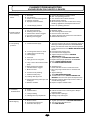
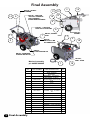
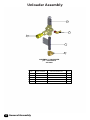
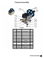
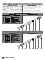
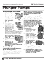
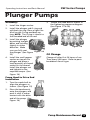
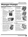
Service Manual
440C-G
p/n N84001
______________________________________________________
INSTALLATION DATE
PART NUMBER
______________________________________________________
MAKE/MODEL
SERIAL NUMBER
______________________________________________________
SELLER
______________________________________________________
ADDRESS
CITY/STATE/ZIP
NOTES:
Phone: 1-877-7ZEPPRO (1-877793-7776)
Email: zepprofessional@zep.
com
Zep Inc.
1310 Seaboard Ind. Blvd.
Atlanta GA 30318
Specifications
PERFORMANCE
Discharge Volume
Pump Head Pressure
GENERAL
Minimum Inlet Water Pressure
Spray Tip
Weight
Hose Assembly
Hose Assembly
Hose
Coupler
Belt
Trigger Gun & Wand
- Trigger Gun
- Trigger Wand
PUMP ENGINE
Engine
Engine Horsepower
Engine Fuel
Engine Make
Engine Regulator
Engine Charge Rate
Engine Start
Engine Oil Filter
Engine Air Filter
Engine Air Pre-Cleaner
4.0 gal/m / 15.1 L/m
4000 psi / 275 bar
over 65 psi may require water inlet regulator
10 psi / 0.68 bar
(#4.0 - 15˚) p/n JA0-15040-2
435 lbs / 170 Kg
3/8” x 50’ 4000psi
p/n 3401-00701A
3/8” x 50’ p/n K02-03150E5
p/n W04-34155-A
p/n R02-00246
p/n J06-00158-B
p/n J06-00158
p/n J06-00104EZ
F05-00439B
16 HP / 12 KW
Gasoline
Vanguard
P/N F05-00440-02
20 AMP
Electric
p/n F05-00441-02
p/n F05-00422-3
p/n F05-00442-4
Specifications OPERATION TABLE OF CONTENTS
GAS ENGINE DRIVEN COLD WATER CLEANER
SAFETY INSTRUCTIONS
• Safety Symbols
• General
SERVICE
Pg. #
• Pump
• Fuel Filter
• Trigger Gun
• Unloader
• Machine Breakdown
• Chemical Metering Valve
3
3
OPERATION
•Pre Start-Up
•Start-Up
•Shut Down
4
4
5
Pg. #
See
See
See
See
See
Parts
Parts
Parts
Parts
Parts
List
List
List
List
List
Section
Section
Section
Section
Section
See Parts List Section
COMPONENT ADJUSTMENT
MAINTENANCE
Chemical Metering
Machine
• Belt Tension
6
• Spray Tip Maintenance
• Flushing
• Storage
• Schedule
6
6
6
7
• Flow Adjustment
See Parts List Section
Unloader
• Pressure Adjustment
See Parts List Section
WARRANTY
Inside Back Cover
SPECIFICATIONS
Inside Front Cover
TROUBLESHOOTING
Machine
• Pump
8
See Parts List Section
SCHEMATIC
Supersedes 05-12-06 Z08-00485TC
2
Last Page
05-17-06 Z08-00485TC
SAFETY AND OPERATION
GAS ENGINE DRIVEN COLD WATER CLEANER
GENERAL SAEFTY
MACHINE UNPACKING
ALL CLEANERS ARE CAREFULLY INSPECTED AND
CARTONED TO PROTECT AGAINST SHIPPING
DAMAGE. IF THERE IS DAMAGE OR MISSING PARTS,
THE TRANSPORTATION COMPANY AGENT SHOULD
MAKE A NOTATION TO THAT EFFECT ON THE BILL.
REFER TO THE PARTS LIST IN THIS MANUAL AND
ADVISE WHAT PARTS ARE MISSING OR DAMAGED.
IF AVAILABLE, GIVE THE INVOICE NUMBER ON ALL
ORDER BILLS. THIS PROCEDURE WILL ENABLE
NEEDED PARTS TO BE SHIPPED QUICKLY.
1. Before operating this machine, read and observe all
safety, unpacking, and operating instructions. Failure
to comply with these instructions could create a
hazardous situation.
READ ALL Installation, Operation, and Maintenance
instructions before operating the machine.
4. The operator of this equipment should wear protective
face shields and other protective clothing as required
for safe operation.
NOTE: Refer to CLEANER MODEL for SERIAL NUMBER
location.
5. Always point the gun assembly in a safe direction and
do not direct spray on the cleaner.
NOTE: Dimensions are in inches unless otherwise noted.
6. Do not operate the machine if any mechanical failure
is noted or suspected.
IMPORTANT SAFETY
INSTRUCTIONS
2. The operator of this equipment should not operate this
equipment when fatigued or under influence of alcohol
or drugs.
3. The operator of this equipment should be thoroughly
familiar with its operation and trained in the job to
be accomplished.
8. Do not leave this machine unattended when it is
operating.
9. All installations must conform to all applicable
Local codes. Contact your electrician, plumber,
utility company or seller for details.
The safety alert symbol.
This symbol is used
to identify safety information about hazards that can
result in personal injury.
A signal word (DANGER, WARNING, or CAUTION) is used
with the alert symbol to indicate the likelihood and the
potential severity of injury. In addition, a hazard symbol
may be used to represent the type of hazard
WARNING: RISK OF INJECTION OR
SEVERE INJURY. KEEP CLEAR OF
NOZZLE. DO NOT DIRECT DISCHARGE
STREAM AT PERSONS. THIS EQUIPMENT
IS TO BE USED ONLY BY TRAINED
OPERATORS.
DANGER indicates a hazard which, if not avoided,
will result in death or serious injury.
AVERTISSEMENT:RISQUE D’INJECTION ET
DE BLESSURES GRAVES. SE TENIR À
L’ÉCART DU JET. NE PAS DIRIGER LE JET
DE SOTIE VERS D’AUTRES PERSONNES
CONFIER L’UTILISATION LE JET DE SOTIE
VERS D’AUTRES PERSONNES. CONFIER
L’UTILISATION DE CE MATÉRIEL À UN
OPÉRATEUR QUALIFIÉ.
WARNING indicates a hazard which, if not avoided,
could result in death or serious injury.
CAUTION indicates a hazard which, if not avoided,
might result in minor or moderate injury.
CAUTION, when used without the alert symbol,
indicates a situation that could result in damage to
the equipment.
ADVERTENCIA:RIESGO DE LA INYECCIÓN
O SEVERO LESIÓN. CLARO DE LA
SUBSISTENCIA DEL INYECTOR. NO DIRIJA
LA CORRIENTE DE LA DESCARGA EN LAS
PERSONAS. ESTO EL EQUIPO DEBE SER
UTILIZADO SOLAMENTE POR LOS
OPERADORESENTRENADOS.
Read and understand this “OPERATOR’S
MANUAL” and “LABELS
ON THE MACHINE” before
starting.
Supersedes 05-12-05 Z08-00485
3
05-17-06 Z08-00485
OPERATION
WARNING: Never put hands or fingers in wash
spray. DO NOT point the gun assembly toward
your body or at anyone else. Failure to do this could
result in serious injury.
PRE START-UP
WARNING: Avoid the exhaust areas as they are
dangerously hot during and a short time after
operation.
1. The first time the machine is operated, after repairs
have been made, or if the machine has set for a period
of time (30 days or more) follow the following
procedures.
A. Check the tension of the belt (if so
equipped)
per instructions in MACHINE MAINTENANCE.
WARNING: DO NOT run engine in an enclosed
area. Exhaust gases contain carbon monoxide,
an odorless and deadly poison.
10. If a water leak is found, DO NOT OPERATE THE
MACHINE. Shut off the motor and repair.
B. Flush the machine per instructions in MACHINE
MAINTENANCE.
2.
11. Do not start the machine unless the gun assembly is
firmly gripped by the machine operator. Failure to do
this could result in injury from a flying hose and gun
assembly.
CAUTION: If machine has been exposed
to sub-freezing temperatures, it must be thoroughly
warmed to above freezing before operating. Failure
to warm machine can cause damage to the pump
packings and other components.
12. All guards, shields, and covers must be replace after
adjustment are made to prevent accidental contact
with hazardous parts.
13. If chemicals are used in conjunction with this
equipment, read and follow the product label
directions.
14. Do not refuel the machine while it is running or hot.
Allow it to cool sufficiently to prevent ignition of any
spilled fuel. .
15. Drive belts must be inspected and tightened
periodically to operate at optimum levels.
16. Inspect machine for damaged or worn components
and repair or replace to avoid potential hazards.
Do not operate the machine if any mechanical
failure is noted or suspected.
17. Always use the correct size spray tip specified in
the GENERAL section of the MODEL
SPECIFICATIONS or MODEL EXPLODED VIEW.
18. Do not start the engine until you have observed all
safety instructions and operating found in the
operating manual.
SAVE THESE SAFETY
CAUTION: Always use the factory supplied wash
hose with your machine. Do not substitute other
hoses as a potential safety problem may develop.
START-UP
♦
♦
Refer to the MAINTENANCE SCHEDULE for any
maintenance to be performed before
operation
OIL LEVEL: Check the oil level in the water pump.
♦ BELT: Make sure belt tension and condition is as
specified in MACHINE MAINTENANCE.
♦ METERING VALVE ( if so equipped): Make sure the
metering valve is closed before operation. If air enters
the system through this valve, poor performance and
machine damage will occur. Refer to the metering
valve insert for proper operation.
♦ WATER SUPPLY: This machine must have a water
supply meeting or exceeding the maximum discharge
volume specified in the PERFORMANCE section, and
a minimum water inlet pressure of 40 PSI /12.1KGM.
1.
Turn water supply.
2.
With the gun assembly in hand (on trigger gun models
hold the trigger gun valve in open position) and with
a good flow of water turn the switch to the “pump”
position.
INSTRUCTIONS
CAUTION: A good flow of water must be flowing
from the end of a gun for 30 seconds, before
proceeding. Lack of water can cause damage to
the water pump and like components.
Supersedes 08-19-04 Z08-02830A
4
05-12-06 Z08-02830A
CAUTION: On a machine equipped with a trigger
gun valve, if the trigger gun valve remains in the closed
position for more than 3 minutes, water pump damage
may occur.
4.
TO APPLY CHEMICAL:
A. Mix chemicals per label instructions. Use
necessary safety precautions.
B. Insert chemical screen into chemical container
C. Adjust metering valve (if so equipped).
D. If the gun assembly is equipped with variable or
multiple nozzle assembly, adjust as desired.
TO RINSE:
A. Close the chemical metering valve (if so
equipped). NOTE: It is advisable to dip the
chemical screen in a container of clean water
and open the valve 1 minute to clean the valve of
any remaining residue.
B. If the gun assembly is equipped with variable or
multiple nozzle assembly, open and close to clean
nozzle of any remaining residue.
C. Start from the top, working downward
long, overlapping strokes.
using
SHUT-DOWN
1. Shut down per engine owners manual.
2. Turn off the water supply.
3. If freezing conditions may exist, refer to STORAGE
in MACHINE MAINTENANCE.
4. Refer to engine owners manual for proper engine
storage.
Supersedes 08-19-04 Z08-02830B
5
05-12-06 Z08-02830B
CAUTION: DO NOT RUN PUMP WITHOUT
WATER, AS THIS WILL CAUSE DAMAGE TO
THE PUMP AND VOID WARRANTY.
MACHINE
MAINTENANCE
Gas Engine Driven Cold Water Cleaners
DEFLECTION
2.
When clean water flows from the gun, turn switch
to the “OFF” position.
6.
Reinstall spray tip.
7. With the gun assembly in hand, turn on the switch.
On trigger gun models hold the trigger gun valve
in open position.
SPAN
1.
5.
Correct belt tension will allow a 1/64- inch
deflection for each inch of span between pulley
centers with a 6-pound force applied in the middle
of the span.
8.
When clean water flows from the gun, turn switch
to the “OFF” position.
9.
If freezing conditions may exist, refer to
“STORAGE” section.
EXAMPLE: A 6-pound force applied at the middle
of an 8 inch span should produce a deflection of
8/64 inch or 1/8 inch.
10.
Turn off and disconnect the water supply.
Disconnect elctrical supply.
STORAGE
Belts can be tightened or loosened by loosening
the nuts holding the pump assembly to the motor
mount.
Then tighten or loosen
the j-bolt on the motor mount. Retighten the pump
assembly after the desired tension is reached.
1.
Rinse the chemical line by inserting the screen
into a container of clear water and open the
metering valve 1 minute to clean it of any
remaining residue. Be sure the chemical metering
valve is closed when finished.
SPRAY TIP MAINTENANCE
1.
Remove the spray tip from the gun assembly.
2.
Disconnect the water supply.
2.
Blow out debris with compressed air from the
outside in. Any debris remaining in the inlet side
of the nozzle should be cleaned out. If lime or
chemical scale is present in the inlet side, the
nozzle may be soaked in descaling solution or
replaced. If the tip is worn, replace with one
specified in the GENERAL section of MODEL
SPECIFICATIONS or MODEL
EXPLODED
VIEW.
3.
Remove the spray tip nozzle from gun assembly
and wire to machine.
4.
Attach an air chuck to the air valve stem on the
pump assembly. With the trigger gun in the open
position, apply air until a mixture of air and very
little water is coming from the gun wand .
5.
Fill a 1-gallon container with Ethylene Glycol type
antifreeze. Minimum should be a mixture of ½
antifreeze and ½ water strength before each use,
as the antifreeze will dilute with use.
3.
Before replacing spray tip flush the machine per
“FLUSHING”.
4.
Reinstall Spray tip to gun assembly.
6. Install a 2-ft garden hose to the water inlet. Insert
the other end into a container of antifreeze solution.
FLUSHING
1.
7. With the gun assembly in hand, turn on the switch.
On trigger gun models hold the trigger gun valve
in open position.
Connect machine to a pressurized water supply
meeting the requirements specified in the
GENERAL
section
of
the
MODEL
SPECIFICATIONS.
2.
Turn on the water supply.
3.
Remove the spray tip from gun assembly.
4.
With gun assembly in hand, start engine. On
trigger gun models hold the trigger gun valve in
open position.
Supersedes 02-16-01 Z08-027666
8.
Turn off the switch just prior to running out of
antifreeze mixture.
9.
Disconnect gun and hose.
10. Place machine and battery in a dry place protected
from weather conditions.
1
05-17-06 Z08-027666
MACHINE MAINTENANCE SCHEDULE
ENGINE DRIVEN OIL FIRED COLD WATER
CLEANERS
DAILY
EACH HR AFTER FIRST
8 HRS
50 HRS
EVERY
50HRS
EVERY
100 HRS
EVERY
500 HRS
YEARLY
OIL BATH WATER PUMP:
Oil Level - check and add as needed per PUMP
SERVICE insert.
Oil Change- drain and refill per PUMP SERVICE
insert. CAUTION: Used oil must be disposed into
an enviromental safe container and brought to an oil
recycling center.
Oil contamination- Milky color indicates water.
HOSES:
Blistering, Loose Covering
Abrasion of cover exposing reinforcement.
Cuts exposing reinforcement.
BELTS:
Cracks or fraying
Belt Tension- For correct tension, see MACHINE
MAINTENANCE insert.
LEAKS:
Check for water and buildup of scale at pipe
connections.
SCREEN-WATER:
Check Inlet Hose Screen for debris.
Check float Tank Hose Screen ( if so equipped)
for debris.
Check Water Filter (if so equipped) for debris see
breakdown elsewhere in this manual.
SPRAY TIP:
Check tip for debris.
GUARDS AND SHIELDS:
Check that all guards and sheilds are in place and
secure.
PUMP MOTOR WITH GREASE FITTINGS:
Remove drain plug. Use 1 or 2 full strokes of shell
“DOBLIUM RB”, Cheveron”SR1 No.2” or Texaco
“PREMIUM RB”. Operate for 20 minutes and replace
drain plug.
FREEZING TEMPERATURES:
Freezing temperatures break coils and water
pumps. See STORAGE in the MACHINE MAINTENANCE section for cold weather instructions.
Supersedes 11-23-03 Z08-02767
x
05-12-06 Z08-02767
CLEANER TROUBLESHOOTING
ENGINE DRIVEN COLD WATER CLEANERS
TROUBLE
1. Poor cleaning
action.
2. Machine will not
draw chemical.
3. Low operating
pressure.
POSSIBLE CAUSE
REMEDY
F. Low discharge pressure.
A. Connect the machine to a water softner.
B. See “Low operating pressure.”
C. See “machine will not draw chemical.”
D. Obtain proper chemical.
E. Mix chemical per the label. Follow all the mixing,
handling, application,and disposal instructions.
F. See “Low operating pressure.”
A. No chemical solution.
B. Metering valve not open.
C. Chemical line strainer clogged.
D. Air leak in Chemical line.
E. Metering valve clogged.
A. Replenish supply.
B. Turn metering valve knob to open.
C. Remove screen and cleaan.
D. Tighten all fittings and hoses for the chemical line.
E. Disassemble and clean.
A. Insufficeint water supply.
A. The water supply must meet or exceed the maximum
discharge volume specified in the PERFORMANCE
section, and minimum water inlet pressure specified
in the General section of the MODEL SPECIFICATIONS
section.
B. Use larger water supply hose.
C. Use shorter water supply hose.
D. Tighten belt per instructions in MACHINE
MAINTENANCE insert.
E. Replace bely per CLEANER EXPLODED VIEW.
F. Replace with spray tip specified in the GENERAL
section of MODEL SPECIFICATIONS.
G. See PUMP TROUBLE SHOOTING.
A. Hard water.
B. Low pressure.
C. Little or no chemical being drawn.
D. Improper chemical.
E. Improper chemical mixture.
B. Incoming water hose too small.
C. Water supply hose too long.
D. Belt slippage.
E. Worn belt.
F. Spray tip worn or wrong size.
G. Dirty or worn check valves in water
pump.
H. Water supply hose kinked.
I. Inlet filter screen clogged.
J. Motor runs slow.
K. Air leak in inlet plumbing.
L. Defective water pump.
M. Leaking discharge hose.
N. Chemical metering valve open and
sucking air.
O. Defective unloader.
4. Excessive,
unusual noise.
5. Belts slipping.
H. Straighten hose.
I. Clean water filter screen or hose inlet screen.
J. See “Pump engine starts slow or overheats and
stops.”
K. Tighten all fittings.
L . See PUMP TROUBLESHOOTING.
M. If a water leak is found, DO NOT OPERATE THE
MACHINE. Disconnect the power andreplace hose.
N. Resupply chemical, place soap screen in water, or
shut off metering valve.
O. Repair or replace unloader valve.
C. Pulleys rubbing.
D. Misalignment of pump &motor
A. See PUMP TROUBLESHOOTING.
B. Call service technician or take engine to Reapir/
Warranty station.
C. Adjust shields or pulley(s).
D. Realign pump and engine.
A. Belts too losse.
B. Excessive back pressure.
C. Defective water pump.
A. Tighten per instruction on MACHINE MAINTENANCE.
B. See “Excessive Back Pressure.”
C. See PUMP SERVICE.
A. Pump.
B. Defective motor.
Supersedes 01-16-04 Z08-02768
05-09-06 Z08- 02768
x
CLEANER TROUBLESHOOTING (CONT.)
ENGINE DRIVEN COLD WATER CLEANERS
TROUBLE
POSSIBLE CAUSE
REMEDY
6. Excessive back
pressure.
A. Spray tip built up with lime.
B. Water pump turning too
fast.
.
A. Remove and clean, or replace spray tip with tip
specified in GENERAL section of MODEL
SPECIFCATIONS.
B. See MODEL SPECIFICATIONS.
7. Excessive
vibration.
A. Defective belt.
B. Defective Pump.
C. Defective accumalator.
A. Remove and replace using belt specified in
CLEANER EXPLODED VIEW or the GENERAL
section of MODEL SPECIFICATIONS.
B. See PUMP TROUBLESHOOTING.
C. Recharge/replace.
8. Spray pattern is
broken or
irregular.
A. Remove and clean spray tip per SPRAY TIP
A. Clogged spra tip.
B. Worn or incorrect spray tip.
MAINTENANCE in MACHINE
MAINTENANCE.
B. Remove and replace with tip specified in the
GENERAL section of MODEL
SPECIFICATIONS or MODEL EXPLODED.
9. Engine will not
start.
A. No fuel
B. Plugged fuel filter.
C. Defective or corroded
battery cable
D. Defective engine.
A. Replenish fuel as specified in engine owners
manual.
B. Change engine fuel filter.
C. Drain and replenish fuel.
D. Clean cables and cable ends.
E. Call service technician.
10. Engine starts
slow or overheats
and stops.
A. Improper fuel.
B. Excessive back pressure.
C. Defective engine
D. Dirt in fuel line or filters.
E. Incorrect oil level
F. Engine overloaded.
G. Dirty air cleaner.
H. Faulty spark plug.
A. Replenish fuel as specified in engine owners
manual.
B. See “Excessive Back Pressure.”
C. Call service technichian, or take engine to
Repair/Warranty station.
D. Clean line or replace filter.
E. Check oil level per engine owners manual.
F. See “Excessive Back Pressure”
G. Change air cleaner filters per engine owners
manual.
H. Change plug and set gap per engine owners
manual.
Supersedes 01-16-04 Z08-02769
05-09-06 Z08- 02769
x
Final Assembly
13
DECAL, SERIAL
NUMBER
14
DECAL, CAUTION
DO NOT OPERATE
UNATTENDED PUMP MAINTENANCE
6
4
9
17
DECAL,
PROUD TO BE
AN AMERICAN
5
DECAL, WARNING
ENGINE EXHAUST
ITEM
NO.
PART NUMBER
1
3401-00710
2
3
4
5
6
Final Assembly
3
18
DECAL,
TURN WATER ON
DECAL,
FUEL TANK
Macine Assembly
p/n 445SE-000000
DECAL,
MODEL
DECAL, MODEL
445S
7
16
8
15
DECAL, CAUTION
RISK OF EYE INJURY
11
2
12
1
PART DESCRIPTION
ASS'Y, HOSE - 3/8 X 50 2
WIRE 5000PSI
WELDMENT, LIFT
435S-00183
BRACKET
ASSEMBLY, CLEANER 445SE-00603
16HP
WELDMENT, SHIELD535S-05150
PULLEY SS 3 3/4 X 15 1/2
X 25
BRACKET, BATTERY 3/4 X
AS11-00906-PB
9 3/8
D02-00001E
DECAL, SERIAL NO
19
QTY.
1
1
1
1
1
1
7
F04-00451
GROMMET, RUBBER
4
8
H04-13803
H04-19000
10
H04-25007
SCREW, MACHINE
SCREW, THREAD
CUTTING - #10 - 24 UNC X
1/2
SCREW, CAP
6
9
11
H04-25024
SCREW, CAP
2
12
H04-31326
CAP, SCREW
4
13
H06-31300
NUT, LOCK - 5/16"
4
14
H09-12500
RIVET, POP
2
15
J00-15040-2
16
J06-00158-B
1
17
Z01-00014
TIP, SPRAY - #1504
ASSEMBLY, GUN & WAND
- 42"
CAP, VINYL
18
Z01-00017
PLUG, TUBING
2
19
Z01-00084
CAP, FUEL
1
3
2
1
2
Trigger Gun & Wand
J06-00158-B PART LIST
ITEM
PART NUMBER
PART DESCRIPTION
1
J06-00158
Valve, Trigger Gun
2
J06-00104EZ
Assembly, Wand – 42”
3
W04-24225-A
Coupling, Female
9/3/2008
J06-00158
2
1
BEVEL SIDE
TOWARDS BALL
12
3
7
6
4
5
DISHED SIDE
TOWARDS BALL
18
3
13
19
5
14
6
15
16
17
2
8
4
1
19
7
10
9
Final Assembly Repair Instructions
1.
Specifications
Remove screws from
handles and remove handle
housings.
With 18mm socket remove
retainer being careful to
catch the spring and ball as
they fall out of the housing.
Remove and replace parts
with those found in the kit.
Assemble in reverse order.
2.
3.
4.
Maximum Volume
10.0 GPM / 37.9 LPM
Maximum Pressure
5000 PSI / 344.7 BAR
Rated Temperature
300˚ F / 150˚ C
Weight
1.8lbs / 0.8kg
Inlet
3/8” NPT Female
Outlet
¼” NPT Female
All dimensions are in inches unless otherwise noted.
25.4 mm = 1 inch
Kit, Repair Part – Number J06-99158C
Warning: Do not use acid concentrates through the gun. Never secure trigger gun in an open
position (trigger pulled back) by means other than the operator’s hand. Bodily harm may occur if
the operator loses control of the trigger gun.
Caution: Always engage trigger safety latch when not in use.
J06-00158 PART LIST
ITEM
PART NUMBER
PART DESCRIPTION
QTY
1
C07-01300-08
O-Ring – 1/16CS x 5/16ID
1
2
C07-01425
Filter, Water
1
3
J06-00121-07
O-Ring – 3/32CS x 1/8ID
1
4
J06-00121-15
Ball, SS 5/16
1
5
J06-00132-19
Screw, Self Tap – 3.5mm x 18mm
1
6
J06-00158-01
Fitting, Discharge – ¼ FNPT
1
7
J06-00158-02
Pin, Trigger – 5mm x 27.5mm
1
8
J06-00158-03
Cam
1
9
J06-00158-04
Trigger
1
10
J06-00158-05
Latch, Safety
1
11
J06-00158-06
Fitting, Inlet – 3/8 FNPT
1
12
J06-00158-08A
Seat, Valve
1
13
J06-00158-09
Washer, Flat
1
14
J06-00158-10
Washer, Flat - Brass
1
15
J06-00158-11
Housing, Valve
1
16
J06-00158-12A
Retainer, Valve
1
17
J06-00158-13
Spring, Compression
1
18
J06-00158-14
Pin, Valve – 4mm x 44mm
1
19
J06-99158A
Housing, Handle
1
Final Assembly
General Assembly
12
27
10
31
9
28 24
26
15
20
9
17
9
16
P/N R02-00243
BELT, SINGLE V
23
18
14
25
6
11
13
7
1
2
3
4
8
5
29
30
21
22
19
445SE-00603
03-31-2009
ITEM
NO.
1
2
3
4
5
6
PART
NUMBER
535S-00130
AR58-02800
G02-10016B
H06-62503
Z01-00029
H10-50000
7
H05-50001
8
9
H06-25003
H06-31300
10
H06-37500
11
12
13
14
H06-50001
445S-00515
H04-31326
445S-00134
15
F05-00439
16
R04-00006
ITEM
NO.
17
18
PART
NUMBER
R03-00744
F05-00436-2
19
535S-10125
8
20
21
22
445SE-00501
W02-10031
E09-00002-2
2
7
23
H03-31311
24
F04-00455
4
25
F05-00220
8
1
2
1
26
F05-00220-R
27
28
K02-03216A2
K20-00900
PART DESCRIPTION
QTY.
WELDMENT, FRAME
ROD, CRS - 5/8" X 28"
ASS'Y, TIRE & RIM - 13"
COLLAR, SHAFT - 5/8"
CAP, VINYL - ROUND
MOUNT, SHOCK
WASHER, HELICAL
LOCK - 1/2"
NUT, HEX
NUT, LOCK - 5/16"
NUT,LOCK-3/8-16UNC
HEX
NUT, 1/2 - 20UNF
ASSEMBLY, UNLOADER
CAP, SCREW
WELDMENT, MOUNT
ENGINE, GAS - 16HP,
VANGUARD
BUSHING, PULLEY
1
1
2
2
2
4
1
1
29
K33-01500
30
31
W02-00033
W02-00036
PART DESCRIPTION
QTY.
BUSHING, PULLEY
KIT, MUFFLER
1
1
TANK, FUEL - 3 13/16 X
15 5/8 X 17 5/8 4.5 GAL
1
ASSEMBLY, PUMP
BARB, HOSE
PLUG, PIPE
BOLT,J-5/16-18UNC x 3
1/2
GROMMET, RUBBER
CABLE, BATTERY - 20"
EYE/EYE BLACK
CABLE, BATTERY - 20"
EYE/EYE RED
ASSEMBLY, HOSE
HOSE, GAS
HOSE, WATER - 3/8 X
15"
CLAMP, HOSE
CLAMP, HOSE
1
1
1
1
1
2
2
1
1
1
2
2
General Assembly Unloader Assembly
2
4
5
1
3
ASSEMBLY, UNLOADER
p/n: 445S-00515
4/3/2009
ITEM
NO.
General Assembly
PART NUMBER
PART DESCRIPTION
QTY.
1
835S-00514
BRACKET, UNLOADER
1
2
C07-03800X
VALVE, UNLOADER (GREY)
1
3
E08-00010-5
ELBOW, PIPE
1
4
W02-10040-8
BARB, HOSE
1
5
W04-34155-A
COUPLER, 3/8F X 1/2MNPT
1
Unloader Valve Breakdown
C07-03700X,C07-03800X
Unloading Adjustment
1.
2.
3.
4.
5.
Install an appropriate pressure gauge in pump head outlet. The gauge should have a range twice the
operating pressure.
Loosen nut (Item 19) and turn the knob (Item 20) counter clockwise until minimum spring tension.
Open the trigger gun, start the pump, and observe pressure gauge reading. Slowly tighten the knob.
Close and open the trigger gun to check unloading pressure and bypass function of the unloader valve.
The unloading pressure should not exceed operating pressure more than 400 PSI.
Lock the setting by tightening the nut (Item 19)
Note: Once the operating pressure is reached, turning the knob clockwise will increase the unloading pressure
only.
19
20
Specifications
Maximum Flow
*Max Unloading Press.
3650 PSI / 251 BAR
**Max Unloading Press.
4200 PSI / 290 BAR
2.1 LBS / 0.91 KG
Bypass
¼ FNPT
Inlet & Discharge
22
190˚F / 88˚C
Weight
*P/N C07-03700
21
7.8 GPM / 30 LPM
Maximum Temperature
*
6
4*
12
8
* 7
3/8 FNPT
**P/N C07-03800
Repair Parts Package
*C07-03700K – Includes 1 of item #1, 1 of item #2, 1 of item #3, 3 of item
#4, 2 of item #7, 2 of item #13, 1 of item #14, 1 of item #27
15
* 1
23
* 7
* 13
18
* 14
* 13
24
25
*3
17
9*
5
4 *
16
27 *
2*
10
4 *
26
Unloader Valve PART LISTS
ITEM
PART
DESCRIPTION
PART NUMBER
19
QTY
20
21
*
1
8RS6-000SV01
O-Ring – 1/16CS x 1/2ID
1
2
C07-02000-18
Ball, SS 11/32
1
3
C07-02000-20
O-Ring
1
4
C07-02300-08
O-Ring – 11/16ID
3
5
C07-03700-1
Fitting, Outlet – 3/8
1
6
C07-03700-11
Guide Piston
1
7
C07-03700-12
Ring, Anti-Extrusion
2
8
C07-03700-15
Pin, Roll
1
9
C07-03700-21
Guide, Piston – SS
1
10
C07-03700-23
Spring, Compression
1
12
C07-03700-26
Piston
1
13
C07-03700-28
Ring, Anti-Extrusion
2
14
C07-03700-29
O-Ring – 3/32 x 7/16ID
x 3043
1
15
C07-03700-3
Spring, Compression
1
16
C07-03700-4
Orifice, Shutter
1
17
17
C07-03700-6A
Plug, 3/8NPT
2
18
C07-03700-6B
Gasket, Washer – 1/16CS x
5/16 x 7/16OD
2
9*
27 *
19
C07-03700-7
Nut, Ny-Lock
1
20
C07-03700-8
Knob, Adjustment
1
21
C07-03700-9
Follower, Spring
1
*22
C07-0370010C
Spring, Blue
1
**22
C07-0370010D
Spring, Black
1
23
C07-0370018B
Housing, Unloader – 3/8
FNPT
1
24
C07-0370019A
Plug
1
25
C07-0370019B
Gasket, Washer – 1/16CS x
5/16ID x 9/16OD
1
26
C07-03800-24
Guide, Ball
1
27
N07-20028
O-Ring – 1/16CS x 7/16ID
1
*P/N C07-03700
**P/N C07-03800
Unloader Valve
22
6
4*
12
8
7
*
* 1
15
23
* 7
* 13
18
* 14
* 13
*3
24
5
4 *
25
16
2*
10
4 *
26
Pump Assembly
10
9
11
3
5
1
12
6
4
7
2
8
445SE-00501
03-31-2009
ITEM NO. PART NUMBER
PART DESCRIPTION
QTY.
1
4355EB-00513
MOUNT, PUMP
1
2
C04-00144
FILTER, WATER
1
3
E08-00011-58
ELBOW, PIPE
1
4
E10-00005-4
TEE, PIPE
1
5
E15-00010-48
NIPPLE, BRASS 1/2"
1
6
H05-31300
WASHER, FLAT - 5/16
4
7
H05-31304
WASHER
4
8
N07-20048
SCREW, CAP
4
9
N09-00053
PUMP, WATER RK1528HN
1
10
R03-00794
PULLEY, DBL
1
11
R04-00001
BUSHING, PULLEY
1
12
W02-10030-8
BARB, HOSE
1
Pump Assembly MAXIMUM FLOW ....................8.0 GPM / 30.3 LPM
MINIMUM INLET PRESSURE.......15 PSI / 1.02 BAR
MAXIMUM INELT PRESSURE....150 PSI / 10.3 BAR
MAXIMUM TEMPERATURE ....................180°/ 82°C
WEIGHT.....................................0.5 LBS. / 0.23 KG
BYPASS..............1/4 FNPT (C04-00146, C04-00147)
INLET/OUTLET....3/8 NPT (C04-00145, C04-00147)
INLET/OUTLET....1/2 NPT (C04-00144, C04-00146)
DIMENSIONS.....................................1.125" X 3.75"
10
Pump Assembly
1. With wrench on hex behind garden hose nut and
opposite end of glass, unscrew the filter. Be cautious
of the glass tube as it don't fall onto a sharp object.
2. Clean the screen and glass tube.
3. Check o-rings for cuts, cracking or abrasion.
4. Reinstall screen and glass tube onto the machine,
and reinstall the garden hose swivel.
Water Pump
N09-00053
Water Pump 11
12
Water Pump
Pump Maintenance Record
Month/Day/Year
Oil Change
Operating Hours
Oil Brand & Type
Month/Day/Year
Pump Service
Operating Hours
Type of Service
Pump Maintenance Record 13
XW Series Pumps
Operating Instructions and Parts Manual
Plunger Pumps
Service Pumps (continued)
with your fingers
(do not use any
tools you may
damage the seal).
Make sure the seal
is totally seated
against the head
ring. (See Figure
16 & 17)
Figure 17
3.
Place the brass
intermediate ring
squarely over the
high-pressure seal.
4.
Installing the lowpressure seal with
Figure 18
the closed flat
side of the seal being
pushed into the piston guide (when
finished you should be looking at
the open side of the seal). Install
split O-ring (Hold in place with
light grease). (See
Figure 18)
5.
Install the retainer
O-ring.
6.
Squarely seat the
retainer into the
Figure 19
head and push with even
pressure until it snaps into position.
(See Figure 19)
NOTE: Be very careful when working
with the plungers, they are made from
ceramic which is brittle and can be
damaged.
Any time you remove a plunger it is
recommended you replace the slinger
washer, O-ring and top plunger washer.
The washers are a cushion for the
ceramic plunger and compress when
first used, O-ring will set to create a
seal and usually will not spring back
to its original shape. By not replacing
these parts you run the risk
of breaking a plunger or
having a water leak.
Disassembly:
1.
2.
Tools required: 17mm socket, ratchet,
mechanics pick, taper blade gasket
scraper, thread sealant and torque
wrench.
14
Pump Maintenance Record
Insert the gasket
scraper between the
copper washer and
plunger to remove the
washer. (See Figure
21)
Figure 20
Figure 21
3.
Twist and pull the
plunger off the
plunger rod. (See
Figure 22)
4.
Remove the
Figure 22
plunger rod O-ring seal
and split back-up ring with the
mechanics pick.
5.
Remove the brass slinger. At this
point clean any thread locker that
is left on the plunger rod and
retaining nut threads.
Servicing the Plungers
If the plungers are not damaged they
do not need any servicing.
Remove the plunger
retainer nut. (See
Figure 20)
XW Series Pumps
Operating Instructions and Parts Manual
Plunger Pumps
3.
Assembly:
1.
Install the slinger washer.
2.
Install the plunger rod O-ring and
split back-up ring. Place a light film
of oil on the O-ring and back-up
ring. NOTE: The O-ring is closest to
the threaded end of the rod.
3.
Install the plunger
by pushing straight
down and twisting
slightly in either
direction. Make
sure you fully seat
the plunger. (See Figure Figure 23
23)
4.
Install the small copper
washer on top of the
plunger and place a
small quantity of thread
sealant in the thread.
Install the plunger nut
and tighten to the
required torque. (See
Figure 24)
Torque the head bolt as shown in
the tightening sequence diagram.
(See Figure 27 & 28)
Figure 27
Figure 28
Oil Change
Change oil after first 50 hours of use.
Then every 500 hours. Refer to parts
breakdown for oil type.
Figure 24
Pump Head to Drive End
Installation
1.
Turn the crankshaft to
align the plungers as
shown. (See Figure 25)
2.
Place the head evenly
onto the plungers and
push it until it makes
contact with the drive
end of the pump. (See
Figure 26)
Figure 25
Figure 26
Pump Maintenance Record 15
Pump Maintenance
XW Series Pumps
Operating Instructions and Parts Manual
Plunger Pumps
3.
Use the needle
nose pliers to
remove the valve.
(See Figure 7)
4.
Use a small probe
to move the poppet
Figure 7
up and down to assure that
the valve is functioning properly
and that no debris is stuck in the
valve.
5.
Using the mechanics pick remove
the valve seat O-ring and inspect
for any damage, replace if
necessary.
Valve Assembly:
Service Pumps
1.
Servicing the Valves
The inlet and discharge valves in this
series pumps are all the same. The
valves are located under the six 27mm
hex plugs. The inlet valves are located
on the lower row and the discharge
valves are located on the top row of the
pump head.
Tools required: 27mm socket, ratchet,
needle nose pliers,
mechanics pick and
torque wrench.
Valve Removal:
1.
2.
Remove the valve
cap. (See Figure 5)
Inspect the valve cap
O-ring for any damage,
replace if necessary. (See
Figure 6)
Figure 5
Pump Maintenance
2.
Insert the
valve assembly
squarely into the
port pushing it
into the O-ring.
3.
Install the valve
cap and torque
to the proper
specification. (See Figure
9)
Figure 8
Figure 9
Servicing the Packings/Seals
To access the water seals for inspection
or replacement, you will first need to
remove the head of the pump.
Tools required: 8mm hex socket, ratchet,
(2) long screwdrivers, reversible pliers,
mechanics pick and torque wrench.
Figure 6
16
Install the valve seat
O-ring squarely into
the bottom of the
manifold. (See Figure
8)
XW Series Pumps
Operating Instructions and Parts Manual
Plunger Pumps
Service Pumps (continued)
5.
With your finger
pull out the brass
intermediate guide
ring. (See Figure
13)
6.
With your fingers
pull the high-pressure
seal and head ring
out of the head.
(See Figure 14)
7.
The low-pressure seal
is located in the brass
seal retainer. Using
the mechanics pick, go in Figure 14
between the seal
and retainer and
pull the seal straight
out. NOTE: Models
have a split support
O-ring. (See Figure
15)
Disassembly:
1.
First remove the eight 8mm head
bolts.
2.
Place the
screwdrivers as
shown between the
head and crankcase
of the pump, lifting
one up and the
other down. The
head should start
to lift off of the
plungers. (See
Figure 10)
Figure 10
Figure 13
3 . When you
remove the
head you may
notice that some
of the water
Figure 15
seals have stayed on the Figure 11
8. Remove the seal retainer
plungers and some in the
O-ring with the mechanics pick.
head. To remove the seals from the
plungers simple turn the assemblies Assembly:
and pull off. (See Figure 11)
1. Install the plastic head ring into the
4. If the seal assemblies are in the
head (the flat side
head use the reversible
is on the bottom).
pliers to grab the seal
2. Install the highretainer on the inside of
pressure seal. Place
the outside ring, twist
the seal so the
the retainer in either
open “V” portion
direction (this is done
is toward the head
Figure 16
to free the retainer Oring. You need to place the
ring which is stuck to
seal at an angle and pull and push
Figure 12
the manifold) and lift out.
to work the seal into position
(See Figure 12)
Pump Maintenance 17
Troubleshooting
Pump
Trouble
Possible Cause
Remedy
Excessive play on
crankshaft
Defective bearings.
See “Worn bearing.”
Excess shims.
Set up crankshaft.
Loud knocking in pump
Loose connecting rod screws.
Tighten connecting rod screws per PUMP
SPECIFICATIONS
Replace connecting rod per PUMP MAINTENANCE.
Replace bearings per PUMP MAINTENANCE.
Tighten plunger screw per PUMP SPECIFICATIONS.
Oil leaking in the area of Worn crankshaft seal, bad bearing, Remove and replace.
water pump crankshaft grooved shaft, or failure of retainer
o-ring.
Worn connecting rod.
Worn bearings.
Loose plunger bushing screw.
Oil leaking at the rear
portion of the pump
Damaged or improperly installed oil Replace gasket or o-ring.
gauge window gasket or rear cover.
Oil gauge loosed.
Tighten oil gauge.
Rear cover screws loose.
Tighten rear screws to torque values in PUMP
SPECIFICATIONS.
Pump overfilled with oil, displaced Drain oil. Refill to recommended oil level as stated in
through crankcase breather hole in OIL LEVEL in PUMP MAINTENANCE.
oil cap/dipstick.
Water in crankcase
May be caused by humid air
condensing into water inside.
Worn or damaged plunger screw
o-ring.
Maintain or step up lubrication schedule.
Worn bearing
Excessive belt tension.
Oil contamination.
See BELT TENSION in MACHINE MAINTENANCE.
Check oil type and change intervals per PUMP
SPECIFICATIONS.
Short bearing life
Excessive belt tension.
Misalignment between pump and
motor.
Oil has not been changed on
regular basis.
See BELT TENSION in MACHINE MAINTENANCE.
Re-align pump and motor.
Damaged plunger bushing.
Worn connecting rod.
Excess pressure beyond the
pump’s maximum rating.
High water temperature.
Replace plunger bushing.
Replace connecting rod.
Match pressure stated in PUMP SPECIFICATIONS.
Normal wear.
Remove and replace.
Debris.
Check for lack of water inlet screens.
Short seal life
Dirty or worn check
valves
18
Troubleshooting
Remove and replace. See PLUNGER SERVICE in
PUMP MAINTENANCE.
Check oil type and change intervals per PUMP
SPECIFICATIONS.
Lower water temperature stated in PUMP
SPECIFICATIONS.
Presence of metal
particles during oil
change
Failure of internal component.
Remove and disassemble to find probable cause.
New pump.
New pumps have machine fillings and debris
and should be drained and refilled per PUMP
SPECIFICATIONS.
Water leakage from
under head
Worn packing.
Install new packing.
Cracked/scored plunger.
Failure of plunger retainer o-ring.
Remove and replace plunger.
Remove and replace plunger retainer o-ring.
Loud knocking noise in
pump
Pulley loose on crankshaft.
Check key and tighten set screw.
Defective bearing.
Worn connecting rod, crankshaft,
or crosshead.
Remove and replace bearing.
Remove and replace.
Frequent or premature
failure of the packing
Scored, damaged, or worn plunger. Remove and replace plungers.
Overpressure to inlet manifold.
Abrasive material in the fluid being
pumped.
Excessive pressure and/or
temperature of fluid being pumped.
Over pressure of pumps.
Running pump dry.
Reduce inlet pressure.
Install proper filtration on pump inlet pumping.
Low Pressure
Dirty or worn check valves.
Worn packing.
Belt slipping.
Improperly sized spray tip or
nozzle.
Inlet filter screen is clogged.
Pitted valves.
Clean/replace check valves.
Remove and replace packing.
See BELT TENSION in MACHINE MAINTENANCE.
See MACHINE SPECIFICATIOSN for specified spray
tip or nozzle.
Clean inlet filter screen.
See VALVE SERVICE in PUMP MAINTENANCE.
Erratic pressure; pump
runs rough
Dirty or worn check valves.
Clean/replace check valves.
Foreign particles in valve
assemblies.
High inlet water temperature.
See temperature in PUMP SPECIFICATIONS.
Excessive vibration
Dirty or worn check valves
See “Dirty or worn check valves.”
Scored plungers
Abrasive material in fluid being
pumped.
Install proper filtration on pump inlet plumbing.
Fitted plungers
Cavitation.
Decrease inlet water temperature and/or increase inlet
water pressure.
Check pressures and fluid inlet temperature. Be sure
they are within specified range.
Reduce pressure.
Do not run pump without water.
Troubleshooting 19
Warranty Policy
Machines are guaranteed to be free from defects in material or workmanship
under normal use and service for period of one year after delivery from the
factory. Any part (other than vendor items) that is determined to be warranty
will be repaired or replaced at NO CHARGE provided the warranty
registration form is filled out in its entirety and the part is sent back freight
prepaid. Any replacement parts accepted as warranty will be returned to
you freight prepaid.
All parts supplied to us by other manufacturers will be subject to their
guarantee and warranty. Generators, motors, and engines are required by
vendors to be repaired or replaced by authorized warranty repair stations.
The manufacturer will assist you in locating warranty stations around the
country in cases where that is necessary. Select items carry a six-month
warranty such as unloaders, triggers guns, etc.
The manufacturer, at its option, will repair or replace defective parts only,
and does not allow for field labor charges for removal, installation, analysis,
travel expense, or special freight expenses incurred for replacement parts.
Warranty does not apply to normal wear and tear including, but not limited
to, freezing damage, freight damage, damage caused by misuse or
misapplication, chemical related failures, contaminated filters and screens,
moisture related fuel pump failures, stuck check valves, pump packings or
seals, nozzles or orifices, paint, hoses, and gauges.
Warranty 21
For full warranty information, contact your delivering distributor or contact the manufacturer at [email protected]