1
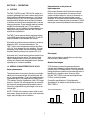
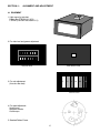
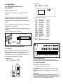
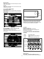
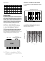
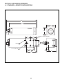
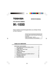
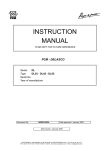
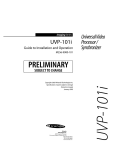
TMC-7 / TMC-6
HIGH RESOLUTION
CCD COLOR CAMERA
OPERATIONS
MANUAL
REV. 7/6/95
TABLE OF CONTENTS
1. OPERATION
Outline
Special Characteristics of a CCD
1
1
1
2. SPECIFICATIONS
2
3. THEORY OF OPERATION
Operation Principles of the CCD
Mechanism of the CCD Electrical Charge Transmission
Interline-Transfer Organization of the CCD Image Sensors
Instructions for Powering TMC-7/TMC-6
2
2
3
4
4
4. ALIGNMENT AND ADJUSTMENT
Equipment
Preparation
Adjustment Procedures
6
6
7
7
5. RGB OPERATION (OPTIONAL)
CCA-7 RGB "Breakout" Module
9
9
6. IMAGER COLOR FILTERS
Diagram of Complementary Mosaic Filter
Spectral Response With Optical Filter (IR Cut Filter)
9
9
9
7. TIMING CHART
10
8. MECHANICAL DRAWINGS
11
SECTION 1: OPERATION
Patterned noise on the picture at
high temperature
1.1 OUTLINE
Dark current (thermal noise) is inherent in semiconductors. At room temperature, the amount of dark
current in all photosensors is very close. However, as
the temperature rises, the amount of dark current
increases. As a result, the relative difference between
the dark current of each photosensor increases. This difference also causes the patterned noise on the picture.
The TMC-7 (NTSC model) / TMC-6 (PAL model) is a
compact, lightweight color video camera which uses a
high resolution solid state image sensor - the Charge
Coupled Device (CCD). The CCD camera produces
less geometrical distortion and has higher resistance
to vibration and shock when compared with a camera
using a pickup tube. These features make the camera
suitable for both industrial and CCTV surveillance
applications. It is also suitable as an input device in an
image processing system since the TMC-7N offers
superb color reproduction.
Light streak.....Smear
The TMC-7 series cameras feature separate outputs
for the RGB signals (when used with CCA-7) and Y/C
output in addition to the standard VBS output.
All models have external access switches to enable or
disable the AGC, and auto-white balance. The
TMC-7 series uses complementary stripe color filters
of Cy, Gr, Ye to generate all color variations. The complementary color system has the advantage of better
sensitivity than the primary color system of R, G, B.
Very bright object
False signal
All models use C-mount lenses and have a back focus
adjustment and auto iris output. The remote imager
option is designed with a C-mount to achieve a tiny
remote color camera with changeable lenses. Remote
capability up to 2 meters is available.
When vertical stripes or straight lines are shot, they
may look wavy ( Moire effect ).
Blemish-free imagers
1.2 SPECIAL CHARACTERISTICS OF A CCD
CCD photosensor elements generate electronic
charges which ultimately produce horizontal and vertical rows in the CCD image sensor. Thus, any malfunctioning photosensor element could eventually cause a
blemish on the monitor screen. However, all the
PULNiX TMC-7/TMC-6 cameras have blemish-free
CCDs to avoid this problem.
Smear phenomenon
This phenomenon occurs when shooting a very bright
object (such as electronic light, fluorescent lamp, the
sun or a strong reflection.) Due to the interline-transfer
organization of the CCD image sensors (Refer to the
"The Interline-Transfer Organization of the CCD Image
Sensors", Section 3.3), this phenomenon is caused by
the electronic charges generated beneath the photosensors by a light with a long wavelength, such as an
infrared light.
Consult the specifications in "Comprehensive
Specifications" for details on the blemishes of the
TMC-7/TMC-6.
At room temperature
NOTE: PULNiX color cameras contain a filter to minimize smear. Smear should only occur under extremely
bright, and point light source conditions.
Level of dark current
1
At high temperature
SECTION 2: COMPREHENSIVE SPECIFICATIONS
Model
TMC-7 (NTSC)
Imager
Pixel
Cell size
Color filter
Scanning
1/2" interline transfer CCD (6.4 x 4.8 mm)
768(H) x 494(V)
752(H) x 582(V)
8.4µm(H) x 9.8µm(V)
8.6µm(H) x 8.3µm(V)
Cy, Ye, Mg, G complementary color filter
2:1 interlaced, field mode scanning
525 lines, 59.94 Hz
625 lines, 50 Hz
Internal sync only
fH = 15.734 KHz
fH = 15.625 KHz
fV = 59.94 Hz
fV = 50.00 Hz
460(H) x 400(V) TV lines
450(H) x 450(V) TV lines
50 dB (AGC off )
2 Lux F = 1.4 (AGC on)
VBS = 1.0 Vp-p at 75 Ω (NTSC and PAL)
Y (B/W) = 1.0 Vp-p with sync, Chroma = 285 mV at 75 Ω (Y/C or S-VHS )
Through-the-lens auto white balance: memory (std) or
auto-tracking (option) and manual hue adjustment
Max. 32 dB AGC, on-off switchable, manual gain control
0.45
C-mount
12 V DC, 330 mA
-10°C to +50°C
Vibration: 7 G (200Hz to 2000Hz), Shock: 70G
42 x 32 x 133 mm 1.65" x 1.26" x 5.24"
210 grams (7.3 oz)
12P-02 for NTSC/PAL and Y/C, KC-10 for NTSC/PAL only
12VDC, 500mA
Auto iris lens output and shutter control (SC-7)
Up to 16 fields integration output, auto-tracking white balance
SC-7 shutter control, C-mount mini lenses
Sync
TV resolution
S/N ratio
Min. illumination
Video output
Color balance
AGC
Gamma
Lens mount
Power req.
Operating temp.
Vibration & shock
Size (W X H X L)
Weight
Power cable
Power supply
Auto iris connector
Functional options
Accessories
TMC-6 (PAL)
SECTION 3: THEORY OF OPERATION
3.1 OPERATION PRINCIPLES OF THE CCD
Transmission of electrical charge
A CCD (Charge Coupled Device) consists of MOS
(Metal Oxide-Silicon) capacitors arranged in a regular
array. It performs three functions connected with handling electrical charges:
When high voltage is applied to the electrodes, a
deeper well is formed. When low voltage is applied, a
shallower well is formed. In the CCD, this property is
used to transmit electrical charges. When a high voltage is applied to the electrodes, a deep electric potential well is formed and electrical charge flows in from
the neighboring wells. When this is repeated over and
over among the regularly arranged electrodes, the
electrical charge is transferred from one MOS capacitor to another. This is the principle of CCD electrical
charge transmission.
Photoelectric conversion (photo sensor)
Incandescent light generates electrical charges on the
MOS capacitors, with the quantity of charge being proportional to the brightness.
Accumulation of electrical charges
When the voltage is applied to the electrodes of the
CCD, an electrical potential well is formed in the silicon
layer. The electrical charge is accumulated in this well.
2
3.2 MECHANISM OF THE CCD ELECTRICAL
CHARGE TRANSMISSION
The TMC-7 uses a 4-phase drive method CCD. For
simplicity, a 2-phase drive method CCD is explained
below.
ø2
ø1
N-
N
N-
Figure 1 shows an example of the changes which can
occur in potential wells in successive time intervals.
N NP - sub
N
N-
N
potential profile
t1
At t1, the electrode voltages are fH1>fH2, so the
potential wells are deeper toward the electrode at the
higher voltage fH1. An electrical charge accumulates
in these deep wells.
N-
t2
time
t3
N, N- * : N type impurity
At t2, the clock voltages fH1 and fH2 are reversed;
now the wells toward the electrode at voltage fH2
become deeper while those toward the electrode at
fH1 become shallower. So the wells at fH2 are deeper
than those at fH1 and the signal charge flows toward
the deeper wells.
potential profile
* - (minus) shows lower
impurity concentration
transfer direction
Operating Pulse Waveforms (ø1, ø2 or øH1, øH2)
V1
ø2 V0
ø1 V1
V0
V1 > VO
At t3, the electrode voltages have not changed
because of t2, so the signal charge flows into the wells
toward the electrode at fH2; one transmission of electrical charge is completed. This action is repeated over
and over to execute the horizontal transmissions.
t1 t2
t3
t
Figure 1
Vertical transfer
4 Phase CCD Drive
The vertical shift register transfers charges using a
four-phase drive mode. Figure 2 shows an example of
the changes which can occur in potential wells in successive time intervals. At tO, the electrode voltages are
(V1 = V2)>(V3 = V4), so the potential wells are deeper
toward the electrode at the higher voltages V1 and V2.
Charges accumulate in these deep wells.
V1
V2
V3
V4
t0
t1
t2
At t1, the electrode voltages are (V1 = V2 = V3)>(V4),
so the charges accumulate in the wells toward the
electrode at V1, V2 and V3.
t3
t4
At t2, the electrode voltages are (V2 = V3)>(V4 = V1),
so the charges accumulate in the wells toward the
electrode at V2 and V3. Electrode voltage states at t3
and after are shown below.
t5
t6
t7
t8
t3(V2 = V3 = V4)>(V1)
t4(V3 = V4)>(V1 = V2)
t5(V4>(V1 = V2 = V3)
t6(V4 = V1)>(V2 = V3)
t7(V4 = V1 = V2)>(V3)
t8(V1 = V2)>(V3 = V4) (Initial state)
transfer direction
Figure 2
These operations are repeated to execute the vertical
transfer.
3
3.3 THE INTERLINE-TRANSFER
ORGANIZATION OF THE CCD IMAGE SENSORS
The TMC-7 CCD video camera module adopts an
interline-transfer organization in which the precisely
aligned photosensor and vertical transmission section
are arrayed interlinearly.
Optional output
Each pin has to be designated for various options
such as Y/C output, integration control, etc. The customer will be required to assign option numbers.
A horizontal shift register links up with the vertical
transmission section. Light variations are sensed by
the photosensors which generate electronic charges
proportional to the light intensity. The generated
charges are fed into the vertical shift registers all at
once. The charges are then transferred from the vertical transmission section to the horizontal shift registers
successively and finally reach the output amplifier to
be read out successively.
Warning
The TMC-7 must use either the 12P Series or C-10
cable. When applying power to the camera, make
sure that none of the exposed leads on the multiple
conductor cable are touching. This may cause damage to the camera. Besides the power connector,
there is a standard BNC video connector on the rear of
the camera.
3.4.1 12-PIN CONNECTOR AND POWER
CABLES
Output section
12-Pin Connector
(818 elements)
Horizontal
shift register
odd line
(513 elements)
even line
odd line
Photo senser
TMC-7/TMC-6
12P-02 Cable
1. GND
2. +12V DC In
3. GND
4. Video Out (VBS)
5. GND
6. N/C
7. Chroma
8. GND
9. Y (B/W)
10. N/C
11. N/C
12. N/C
Gray
Yellow
Red Shield
Red Coax Signal
Orange Shield
Orange Coax Signal
Black Coax Signal
White Shield
White Coax Signal
Brown
Blue
Black Shield
Vertical shift register
12-Pin Figure Power Connector
3.4 INSTRUCTIONS FOR POWERING
THE TMC-7/TMC-6
9
1
2
Connectors
3
The TMC-7 requires 12 V DC (330mA). The power is
obtained through the 12-pin connector located at the
rear of the camera. PULNiX offers a 4-conductor
power cable with mating connector (model# C-10).
For Y/C output, use a 12-pin connector to supply the
power.
11 12
4
4
8
10
5
7
6
12P Series cables available:
3.4.4 AUTO IRIS CONNECTOR
12P-02 2 meters
12P-05 5 meters
12P-10 10 meters
12P-15 15 meters
12P-25 25 meters
12P-X Custom length
12P-02 8-conductor cable for RGB
12P-02MF RGB separator cable (for use with CCA-7
Signal Separator only)
The TMC-7 has a 6-pin auto iris connector located on
the back of the camera. A mating 6-pin connector (PC6P) may be obtained from PULNIX. The lens mount of
the camera is a standard C-mount, and most standard
1/2" auto iris lenses may be used with the TMC7/TMC-6.
6-Pin Connector (Auto
Iris Lens connector)
3.4.2 BACK PANEL ASSEMBLY
6
1
5
LENS
PWR IN
1.
2.
3.
4.
5.
6.
2
4
3
D2
GND
Iris (Video)
+12V DC out
D0
D1
D0, D1, D2 are used for shutter speed control. The
SC-7 provides external manual shutter speed control.
AWB
VIDEO OUT
Warning:
Do not unplug the auto iris lens from the camera while
the camera is powered. This may damage the lens.
Back Panel Assembly
3.4.3 COLOR BALANCE ADJUSTMENT
3.4.5 SC-7 SHUTTER CONTROL
The TMC-7/TMC-6 cameras feature an advanced
color balancing system which utilizes an internal memory. The camera will automatically determine the best
color balance upon powering up. Special comparator
circuitry will compensate for less than perfect power up
color conditions. The camera then retains color balance without the need to continually adjust. The memory feature will achieve excellent color balance for
most routine shooting conditions. The user may reset
the balance at any time by pushing the RESET button
located on the left side of the camera.
The SC-7 is the controller for the shutter speed. It connects to the 6-pin connector of the TMC-7/TMC-6.
(Note: The TMC-7 uses a different controller than all
other PULNiX shutter cameras).
For users wishing the more conventional AUTO
TRACKING mode, a solder jumper at W2 located
inside the camera will convert the camera to auto
tracking. This function allows the camera to continually
balance the color based on the prevailing scene, and
not in reference to the memory. (See page 7)
S
P
E
E
D
C
O
N
T
R
O
L
5
0
1
2
3
4
5
6
7
L
H
L
H
L
H
L
H
D1
L
L
H
H
L
L
H
H
D2
L
L
L
L
H
H
H
H
D0
Shutter
speed
1/60
1/125
1/250
1/500
Integration
(option)
2FLD
4FLD
6FLD
8FLD
1/1000 1/2000 1/4000 1/10000
10FLD 12FLD
14FLD 16FLD
SECTION 4 :
ALIGNMENT AND ADJUSTMENT
4.1 EQUIPMENT
1. Light source for test chart.
Pattern Box PTB-500 (90-130V)
PTB-220 (190-240V--not used in U.S.)
2. For video level and gamma adjustment.
Grayscale Chart
White Window Chart
YL
3. For color adjustment.
(Use color bar chart)
CY
G
W
MG R B
Color Bar Chart
4. For signal adjustment.
Vector scope
Waveform monitor
Oscilloscope
5. Standard Pattern Frame
6
Driver Board
VR2
AGC
= 2.0 V
VR1
AGC MAX = 3.0 V
4.2 PREPARATION
4.2.1 MECHANICAL BACK FOCUS
ADJUSTMENT
AGC
Subject: Resolution chart
VR2
AGC MAX
VR1
1. Mount the manual lens (i.e. Cosmicar 25mm,
F=1.4).
2. Open the lens iris completely and set lens focal
length to minimum for the lens used (e.g. 2 ft.).
Auto-White Balance Board
VR6
B LEVEL
VR7
SHP LEVEL
VR1
CHR LEVEL
VR2
R-Y HUE
VR3
B-Y HUE
VR4
B-Y GAIN
VR5
R-Y GAIN
VR14 Y1 GAIN
VR8
Y LEVEL
VR9
SET UP
VR12 C1 GAIN
VR11 B GAIN
VR10 R GAIN
VR15 YH GAIN
VR16 VAP GAIN
VR17 VAP SLICE
VR18 HOLE
3. If image is not focused properly, set back focus as
follows.
4. Unscrew the M2x3 hex screw on the Front Panel
until the focus ring is loose.
5. Adjust the silver back focus ring until the image is
focused.
6. Repeat steps 4 and 5 if needed.
Back Focus Ring
= 3.4 V
= 3.4 V
= 2.3 V
= 3.5 V
= 3.0 V
= 2.4 V
= 3.2 V
= 2.0 V
= 3.0 V
= 3.0 V
= 3.4 V
= 4.0 V
= 4.0 V
= 3.2 V
= 1.8 V
= 1.5 V
= 2.0 V
Jumper setting
W2
Open (factory setting)
Back Focus
2 Feet
VR12 VR16
VR5 VR3
VR11
VR1
VR8
VR17 VR4
VR2
VR10
VR9
VR6
VR18
4.3 TMC-7 ADJUSTMENT PROCEDURES
VR13 VR14 VR15
4.3.1 PRESET
W2
1
10
J1A
20
29
BCONT2
BCONT2
AWB-SET
TL
VD
BY-OUT
RY-OUT
+5V
GND
GND
Y2 GAIN
Y1 GAIN
C1 GAIN
YH GAIN
VAP GAIN
VAP SLICE
R-Y GAIN
CLP2
WND
B-Y GAIN
B-Y HUE
R-Y HUE
B GAIN
R GAIN
C LEVEL
SET UP
Y LEVEL
SHP LEVEL
B LEVEL
Note: The following controls for the external control
board can be accessed by removing the access port on
the left side of the TMC-7. All other presets and
adjustments are accessed by removing camera cover.
Preset each potentiometer as follows:
Matrix board
VR1
MGC
VR2
W/B (Hue)
VR7
4.3.2 FUNCTION TEST
With above settings, the camera will output a good
picture and you can proceed to the fine tuning process.
= 2.5 V
= 4.0 V
4.3.3 WHITE BALANCE
WHITE
BALANCE
Equipment: Color bar chart (3200°K),
Vector scope, Wave form monitor.
AUTO
SW3
Set AGC and White balance switches to Manual side
(push down ).
Use standard Fujinon lens (Calibrated ) and set the iris
to F=8.
SW2
Burst level
Adjust VR6 so that burst level on Vector scope is on the
75 % line or 286±15mV. If Burst vector is not stable, add
a 22pf capacitor to crystal capacitor. Make sure to select
the right value of C5 located at Driver board.
MANU
VR2
ON
HUE
VR1
OFF
GAIN
AGC
7
R gain, B gain
Adjust VR10 and VR11 so that the white spot on Vector
scope is in the center.
C1 gain
Adjust VR12 so that each color dot on the Vector scope
combines into one spot.
4.3.4 Y LEVEL, SETUP LEVEL
Use Waveform monitor.
Observe the waveform and adjust VR8 to set the white
level to 95 IRE.
Put lens cap on and adjust VR9 so that setup (Pedestal
level) is 5 IRE.
WEN
SMD2
SMD1
SW MODE
100
80
Driver board input/output
10°
60
40
4.3.6 AUTO WHITE BALANCE
Make sure lens is closed. Probe TP2 and adjust VR18
so that the level is at 5V. Now turn lens to F/16, and
make sure DC level goes down to zero. Optimize VR18
so that the above two conditions are satisfied.
0°
20
75
10°
-20
-40
4.3.7 AGC
Switch on to AGC side.
Adjust lens to see if AGC is functioning.
Observe the AGC threshold level and adjust AGC
potentiometer if necessary.
4.3.5 R-Y GAIN, B-Y GAIN, R-Y HUE, B-Y HUE
Use Vector scope.
Adjust VR5 (R-Y gain), VR4 (B-Y gain),
VR2 (R-Y Hue), VR3 (B-Y Hue) to set each vector as
shown below
4.3.8 SHUTTER CONTROL AND INTEGRATION
CONTROL
1. WEN:
2. SMD2:
100
80
3. SMD1:
Write enable output
Select integration mode (Jumper to
GND)
Select shutter mode (Factory set)
10°
60
O E O E O E OE O E O E O E O E O E
40
0°
VD
20
2 FIELD INTEGRATION
75
10°
SG1, SG2
-20
WEN
4 FIELD INTEGRATION
-40
SG1, SG2
WEN
WEN: write enable
4. SW MODE:
8
Auto shutter pulse width mode
Shutter control
Select SMD1 low (GND) and SMD2 high (open).
This is factory set mode. If external control is required,
Speed control
SECTION 6: IMAGER COLOR FILTERS
0
1
2
3
4
5
6
7
D0
L
H
L
H
L
H
L
H
D1
L
L
H
H
L
L
H
H
D2
L
L
L
L
H
H
H
H
6.1 DIAGRAM OF COMPLEMENTARY STRIPE
FILTER
COMPLEMENTARY MOSAIC FILTER
1/60
1/125
1/250
1/500
Integration
(option)
2FLD
4FLD
6FLD
8FLD
1/1000 1/2000 1/4000 1/10000
10FLD 12FLD
14FLD 16FLD
OUTPUT
Continuous shutter
By applying a negative going TTL pulse to pin #8 TRIG
input, the TMC-7 can operate with continuous shutter
speed change. The input pulse must move within a field
timing and the shutter speed is between the pulse edge
and SG1, SG2. In order to activate this function, D0, D1,
D2 must all be low (GND). Unless the TRIG pulse is
applied, CCD charges are kept discharging and when
the pulse is input, the discharge stops and integration
starts up to the transfer gate timing (SG1, SG2).
CY
YE
CY
YE
CY
G
CY
G
MG
MG
YE
MG
G
CY
G
YE
MG
G
CY
G
G
MG
G
MG
G
CY
G
YE
CY
G
YE
CY
G
MG
MG
V SHIFT REGISTER
Shutter
speed
YE
MG
YE
MG
MG
YE
MG
HORIZONTAL SHIFT REGISTER
SECTION 5: RGB OPERATION (Option)
6.2 SPECTRAL RESPONSE WITH COMPLEMENTARY MOSAIC FILTER
5.1 CCA-7 RGB “BREAKOUT” MODULE
CCA-7 is a compact device designed to accept camera outputs via the 12P-02MF (2 - meter) cable from
the camera, and then output the signals (R, G, B,
Sync, and Video) via standard BNC connectors. It also
accepts 12V DC input via a terminal for power.
.9
Relative Response
GND +12V
1.0
To Camera
(Connect 12P-02MF here)
.8
Ye
.7
Cy
.6
G
.5
.4
Mg
.3
.2
.1
.0
400
CCA-7
R
G
B
500
600
Wavelength (nm)
Sync
Video
Note: RGB option is only available when TMC-7 is
modified for use with CCA-7. Contact PULNiX for
further assistance.
9
700
SECTION 7: TIMING CHART FOR TMC-7/TMC-6
HD
6.7µSec
818
768
CCE photo sensors
allocation
Optical
black period
H register
stop period
69.8nSec
Image sensing period
Dummy
H register
Optical
black period
CCD output
signal
Effective picture
period
154
H BLK 10.7µSec
Composite video
output
22
1.54µSec
68
H SYNC
4.75µSec
64
4.47µSec
910
63.56µSec
(1 horizontal line)
10
756
52.81µSec
B45
45
757
758
759
760
761
762
763
764
765
766
767
768
5
B1
B2
B3
B4
B5
1
2
3
4
5
6
7
8
9
10
D1
22
D22
70
B45
B1
763
764
765
766
767
768
45
B1
96
6
SECTION 8: MECHANICAL DRAWINGS
8.1 STANDARD & REMOTE CONFIGURATIONS
146
133
42
PULNiX
32
25
25
M2 (2x)
1/4 - 20 UNC -2B
M2.6 x 7mm. deep (4x)
29
35
8
48
11
50
Notice
The material contained in this manual consists of information that is proprietary to Pulnix America, Inc., and may only
be used by the purchasers of this product. Pulnix America, Inc. makes no warranty for the use of its products and
assumes no responsibility for any errors which may appear or for damages resulting from the use of the information
contained herein. Pulnix America, Inc. reserves the right to make changes without notice.
Warranty
All our solid state cameras have a full three year warranty. If any such product proves defective during this warranty
period, Pulnix America, Inc. will repair the defective product without charge for parts and labor or will provide a
replacement in exchange for the defective product. This warranty shall not apply to any damage, defect or failure
caused by improper use or inadequate maintenance and use.
Revised Printing: July 1995
Pulnix America, Inc.
1330 Orleans Drive,
Sunnyvale, CA 94089
Tel: (408) 747-0300
(800) 445-5444
Fax: (408) 747-0880