1
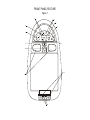
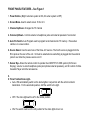
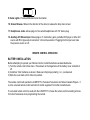
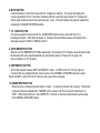
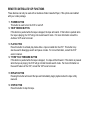
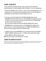
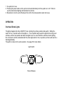
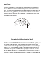
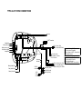
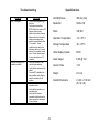
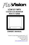
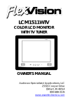
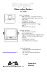
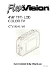
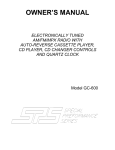
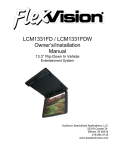
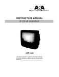
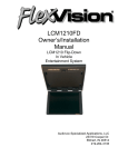
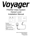
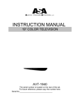
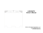
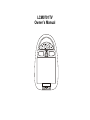
LCM0701TV
Owner’s Manual
S
SCREEN
MODE
CHANNEL
VOLUME
SELECT
TV
V1
V2
AUTO
PRO
POWER
ON
OFF
AUTO
Aux
Headphone
Audio R
Audio L
Video
Headphone
SENSOR
Important Notice
It is unlawful in most jurisdictions for a person to drive a motor vehicle which is equipped with a
television viewer or screen that is located in the motor vehicle at any point forward of the back of the
driver’s seat, or that is visible, directly or indirectly, to the driver while operating the vehicle. In the
interest of safety, the LCM0701TV should never be installed where it will be visible, directly or indirectly,
by the operator of the motor vehicle.
Please note that the state of Rhode Island forbids the installation of such a device in a motor vehicle.
Television Reception
This entertainment system is designed primarily for viewing pre-recorded movies or playing video
games. Television reception in a moving vehicle will be limited and in some areas will not be possible
due to weak and variable signal strength. Television viewing in a stationary vehicle will result in an
improvement, but may still be marginal due to strength. The quality of the picture will not be consistent
with home TV reception. Reception may be affected by the weather and distance from the TV station. A
weak signal may cause the picture to roll, be snowy, or cause some color loss.
Congratulations on your purchase of the Flexvision LCM0701TV drop down TV/Video monitor. The
LCM0701TV has been designed to give you and your family many years of video entertainment in the
mobile environment. Please read the directions that follow to familiarize yourself with the product and to
ensure that you obtain the best results from your equipment. Please note: Installation options vary, see
the individual owner’s manuals for each component in your system to obtain a full understanding of
each component’s operation.
Safety Precaution
For safety reasons, when changing video tapes it is recommended that the vehicle is not in motion, and
that you do not allow children to unfasten seat belts to change tapes or make adjustments to the system.
System adjustments can be accomplished using the remote control unit, while seat belts remain
fastened. Enjoy your Flexvision entertainment system but remember- safety of all passengers remains
the number one priority.
FEATURES
•
•
•
•
•
•
•
•
•
•
•
•
7” TFT (Thin Film Transistor) Active Matrix LCD (Liquid Crystal Display) Monitor
OSD (On Screen Display) for control of Picture Quality and Functions
Screen Mode 16:9 or 4:3
Full Function Remote Control
Television Tuner
Plug in RF Transmitter for wireless RF Headphones
Remote Sensor eye
Four Audio / Video Sources
Headphone / Speaker Amplifier
Two Headphone Jacks for Wired Headphones
Built-In Dome lights
Back-lit Controls for Low Light Operation
FRONT PANEL FEATURE
Figure 1
4
3
6
2
5
1
S
SCREEN
MODE
CHANNEL
VOLUME
SELECT
TV
V1
V2
AUTO
PRO
POWER
SENSOR
7
8
ON
OFF
AUTO
10
11
9
Aux
Headphone
Audio R
Audio L
Video
Headphone
12
FRONT PANEL FEATURES – See Figure 1
1. Power Button- (Bright red when system is ON, dim when system is OFF)
2. Screen Mode- Used to select screen 16:9 or 4:3.
3. Channel Up/Down- Changes the TV channel
4. Volume Up/Down- Controls volume to headphone jacks and external speakers if connected.
5. Auto Pro Switch- Auto Program used to program local channels into TV memory. Press when
vehicle is in a new location.
6. Source Select- Used to select one of the three A/V sources. The fourth source is plugged into the
RCA jacks on the rear of the unit. V2 must be selected once something is plugged into the external
jacks it over rides the previous source on V2.
7. Sensor Eye- Allows the remote control to operate the LCM0701TV’s OSD system (On Screen
Display), volume to wired headphone jacks (and optional external speakers), and for control of Video
Cassette Player and other accessories.
8.
8. Three Position Dome Light• Auto- Will automatically switch on the dome lights in conjunction with the vehicle’s interior
illumination. For the automatic position, shift the switch to the right.
• OFF- The dome lights will be off in the middle position.
• ON- The switch must be in the left position for the dome lights to turn on.
9. Dome Lights- Provide additional interior illumination
10. Screen Release- Slides in the direction of the arrow to release the drop down screen.
11. Headphones Jacks- Allows plug-in of two wired headphones with 1/8” stereo plug.
12. Auxillary A/V Stereo Input- Allows plug-in of Camcorder, game, portable DVD player or other A/V
source with RCA type output connectors. V2 must be selected. Plugging into this input over rides
the previous source on V2.
REMOTE CONTROL OPERATION
BATTERY INSTALLATION
Before attempting to operate your Remote Control, install the batteries as described below.
1) Turn the remote control face down. Press down on the ridged area of the battery cover, and slide it
off.
2) Install two “AAA” batteries as shown. Make sure that proper polarity (+ or -) is observed.
3) Slide the cover back until it clicks into position.
The remote control will operate the LCM0701TV, Flexvision Televisions and Video Cassette Players. It
is not a universal remote control and will not control equipment from other manufacturers.
If a universal remote control is used with the LCM0701TV, choose the remote control encoding scheme
for Action Televisions when programming the remote.
1
6
3
2
4
9
5
8
11
10
12
13
14
16
15
Remote Controlled TV Functions
1. POWER ON/OFF
Press this button to turn the LCM0701TV on. The channel number or current video source will be
displayed on screen, and the picture will appear in a few seconds. Press the button again to turn the
LCM0701TV off.
2. DIRECT ACCESS (0-9) BUTTONS
Use these buttons to make a direct channel selection. The channel number chosen will be displayed
on the screen for about 4 seconds. The direct access is carried out with 0-9 keys (0-99CH). The
“1__” key will not function as it is only used for cable channels above 99.
3. CHANNEL UP/DOWN BUTTONS
Use these buttons to advance to the next higher or lower channel. See also: SKIP/SEARCH
BUTTON.
4. VOLUME UP/DOWN BUTTONS
Use these buttons to raise or lower the volume level of the headphone jacks or external speaker if
installed. They are also used to make adjustments
In picture select mode.
Note: These buttons will not affect the volume of wireless headphones or a wired RF modulator. When
using these devices the volume must be adjusted with the headphone
volume control or with your radio’s volume control.
See page 11 Headphones, or page 12, Wired FM
Modulator).
5. PICTURE SELECT BUTTON
Each time this button is pressed, the screen Picture adjustment display cycles through “adjustment
bars” for CONTRAST, BRIGHTNESS, COLOR, and TINT. Once the desired adjustment
bar is displayed, use the VOLUME UP/DOWN buttons to adjust the setting. The display will
automatically turn off if no adjustments are made within 6 seconds, or if any other button is
depressed.
6. MUTE BUTTON
Press this button to shut off the sound at the headphone stations. The screen will display the
volume adjustment bar for 6 seconds, indicating that the sound has been turned off. Pressing the
button again restores sound to the previously set level. The mute feature may also be released by
pressing the VOLUME UP/DOWN buttons.
7. TV / VIDEO BUTTON
Any video equipment connected to the AUDIO/VIDEO inputs can be used with the TV by
pressing this button. Each time the button is pressed, the Audio/Video source will change in the
following sequence VIDEO1, VIDEO2, and TV.
8. AUTO MEMORY BUTTON
When the AUTO MEMORY BUTTON is depressed, all channels in TV mode are searched and tuned;
all channels with video signals detected are automatically stored. Please refer to page 2 for
more information on TV reception.
9. SKIP/SEARCH BUTTON
This button selects between SKIP and SEARCH mode. In “SKIP mode” the TV only stops on
channels that are programmed into memory when the CHANNEL UP/DOWN buttons are used.
When the SKIP is turned off, the TV will only stop on all active channels.
10. ERASE/WRITE BUTTON
When tuned to a channel press this button to store or erase the channel from memory. The stored
channel numbers are displayed in “GREEN” on the screen, and the non-stored channels are in
“RED”. When skip mode is on, the LCM0701TV will tune to only the stored channels when using
the CHANNEL UP/DOWN buttons.
REMOTE CONTROLLED VCP FUNCTIONS
These features can only be used with an Audiovox Video Cassette Player, if this option was installed
with your video package.
11. POWER BUTTON
This button is used to turn the VCP on and off.
12. “REW” REWIND BUTTON
If this button is pushed while the tape is stopped, the tape will rewind. If this button is pushed while
the tape is playing, the VCP will go into rewind search mode. For more information consult the
Audiovox VCP owner’s manual.
13. PLAY BUTTON
Press this button to activate play mode while a tape is loaded into the VCP. This button may
also be used to disengage search and pause modes. For more information, consult the VCP
owner’s manual.
14. “FFWD” FAST FORWARD BUTTON
If this button is pushed while the tape is stopped, the tape will fast forward. If this button is pressed
while the tape is playing, the VCP will go into fast forward search mode. For more information on
the search feature of the VCP, consult the VCP owner’s manual.
15. REPLAY BUTTON
Pressing this button will rewind the tape and immediately begin playback when the tape is fully
rewound.
16. STOP BUTTON
Press this button to stop the tape.
CHANNEL TUNING SETUP
In order to easily access all available channels, it may be necessary to perform channel autoprogramming whenever the vehicle’s geographic location has changed, i.e. city to city, weak signal area.
1. Press the AUTO MEMORY button on the remote control unit or the AUTO PROGRAM button on the
flip down video unit. You will see the TV cycle through all it’s channels. The built-in microprocessor
will automatically note each channel that is actively broadcasting in your area.
2. (A) To tune only strong clear channels with the CHANNEL UP/DOWN buttons, press the
SKIP/SEARCH button on the Remote Control Unit until “SKIP MODE ON” is displayed on the bottom
of the screen. The TV will now tune only to strong active channels when the UP or DOWN buttons
are used on the monitor or the remote control.
(B) To tune to weak or marginal channels with the CHANNEL UP/DOWN buttons, press the
SKIP/SEARCH button on the Remote Control Unit until “SKIP MODE OFF” is displayed on the
bottom of the screen. Tune to the desired channel using the CHANNEL UP/DOWN buttons or go
directly to the channel by using the 0-9 buttons on the Remote Control.
3. To ERASE a channel, press the ERASE/WRITE button on the Remote Control Unit until “MANUAL
MEMORY XX ERASE” is displayed on screen. To STORE a channel, press the button until the
MANUAL MEMORY XX ADD is displayed on screen.
Note: Please refer to page 2 for more information on TV reception.
TURNING THE LCM0701TV ON OR OFF
Sliding the screen release lock forward will unlock the LCD screen and it will drop down slightly. (Pivot the screen downward until a comfortable viewing angle
is reached). After the unit has been turned on and displaying a picture, adjustment to the viewing angle can be made by pivoting the screen to optimize the
picture quality. The internal friction detent will hold the screen in position while
1. the system is in use.
2. Pressing the power button on the pod or remote will alternately turn the system on or off. When in
use the internal back lighting will illuminate the controls.
3. Remember to turn the unit off and pivot the LCD to the locked position when not in use.
OPERATION
Overhead Dome Lights
The lights integrated into the LCM0701TV are controlled by a three position slide switch. Sliding the
switch to the on position will turn the lights on. The off position will prevent the lights from turning on at
all times, and the auto position will allow the lights to turn on and off with the vehicle’s interior lighting.
Do not leave the vehicle unattended with the dome light switch in the on position, as this could result in a
discharged battery.
The switch is shown in the center position. See page 5 for more details.
Light Switch
Screen Release
Remote Sensor
The LCM0701TV incorporates an infrared sensor, which relays the signals from the remote control to
allow the LCM0701TV and VCP to be controlled simply by pointing it’s remote control at the remote
sensor. This provides control of auxiliary equipment such as an Audiovox Video Cassette Player. The
infrared sensor can relay signals from any manufacturer’s remote control to it’s respective component
connected to the Video 1 and 2 inputs, such as a DVD player. In this case you must use the remote
control supplied with the DVD player.
S
SCREEN
MODE
VOLUME
CHANNEL
SELECT
TV
V1
V2
POWER
AUTO
PRO
SENSOR
1
External Auxiliary A/V Stereo Inputs (Aux Video 2)
These inputs are provided to facilitate the temporary connection of optional audio/video equipment, such
as a camcorder or video game system. To play a source with these inputs, an RCA patch cord is
required to connect the audio / video signals to their respective jacks. Mono audio sources will require
the use of an RCA Y-cable (P/N 0892165) to connect to both right and left inputs, if patch cords are
installed into the AUX inputs, the AUX INPUT 2 will be temporarily bypassed. Once the connections
have been made, turn the LCM0701TV on and press the source button on the LCM0701TV or the TV /
Video button on the remote control until “Video 2” is displayed on the screen. The unit will now play the
audio and video signals from the accessory connected. The remote control will not operate the
accessory components.
LCM0701TV Jack Panel
OPTIONAL ACCESSORIES
Wired Headphones
There are two 1/8” headphone jacks on the LCM0701TV that can be used with any standard stereo
headphones. These jacks are controlled by the volume up/down buttons on the LCM0701TV or the
remote control.
Wireless Headphones
The LCM0701TV includes a RF transmitter
(P/N WTXRF02) for use with optional Flexvision wireless headphones (P/N WHPRF01). Turning the
headphone switch on, and wearing them activates the internal micro switch, (which includes a tuning
knob to tune into the preset frequency on the RF transmitter), which will activate the internal RF receiver.
The volume can be adjusted separately with the controls on the headset. See the documentation
accompanying your Flexvision Wireless Headphones.
Wired FM Modulator (P/N 0190730)
Your video system may be equipped with an RF modulator, that allows you to listen to the LCM0701TV’s
audio signal by tuning your vehicle’s radio to the selected frequency, (88.7 or 89.1- check with your
installer) and tuning on the remote mounted RF modulator switch. (In most cases this toggle switch will
be located underneath the driver’s side of the dash, check with your installer for the exact location.)
Whenever the RF modulator is on, broadcast radio reception will be poor. Turning the remote mounted
toggle switch off will allow for normal radio reception.
Video Output
The LCM0701TV provides a video output for an optional video monitor(s). This output will provide a
video signal that duplicates the signal displayed by the LCM0701TV to an additional monitor or video
display. Please see your installer for more information.
Audiovox Video Cassette Player (Aux Video 1)
In most installations a VCP will be connected to the “Video 1” input. To view a video cassette, turn the
AVP7000/ AVP7285 on and press the source button on its control panel or the TV/Video button on the
remote control unit until “Video 1” is displayed on the screen. The VCP may also be operated with the
remote or the buttons on its face. Inserting a tape into the VCP will turn it on and automatically activate
the play mode. If a rewound tape had been loaded into the VCP, prior to its activation press play on the
VCP or the remote control to view the tape. For more information see the owner’s manual
accompanying your VCP.
TYPICAL SYSTEM CONNECTIONS
Antenna
V1
VCP
To RF Transmitter
To RF Transmitter
Headphone
Yellow (Video In)
White (Audio In Left)
Red (Audio In Right)
Headphone
PIN 1- Power / Red
PIN 2- Power GND / Black
V2
DVD
Accessory
Harness
White (Audio Out L)
Red (Audio Out R)
Yellow (Video Out)
2-PIN IR
Connector
4-PIN
Power
Connector
Negative Switching / GM Type
Gray- Entry Switch / Negative
Black / Constant +12VDC / Dome Circuit
Red- Chassis Ground
PIN 3- Gray / Auto
OR
PIN 4- Black / Common
Positive Switching / Ford Type
PIN 5- Red / On
Gray- Entry Switch / Positive
Speaker or
Headphone
Black- Chassis Ground
Connection
PIN 6- Audio (L) Out / Gray Red- Constant +12VDC / Dome Circuit
PIN 7- Audio GND / Black
PIN8- Audio (R) Out / Green
Yellow RCA (Video)
White RCA (Audio)
Red RCA (Audio)
Optional Product List
Televisions
AVT-988 9” Color Television with Remote (12V)
AVT-1498 13” Color Television with Remote (12V)
VCP and DVD Players for use with TV’s and LCD
AVP-7000 Video Cassette Player (12V)
AVP-7285 Video Cassette Player (12V)
Single Disc DVD Player
Headphones
Wireless Headphones
Headphones with Pivoting Earcup
Headphones with volume Control on Cord
Studio Quality Headphones
Miscellaneous
Remote Controls
Wallmount Family Radio Service with 4 Handsets
Replacement Handset
12V Corded Vacuum
Rechargeable Flashlight
Window Mount TV Antenna
2-Amp Adapter for use with AVP7000 VCP
4-Amp Adapter for use with AVT988 9” and AVT1498 13” TV’s
Wallmount Radios
AM/FM Wallmount Manual Tune w/Cassette Player
AM/FM Wallmount Electronic Tune w/Cassette Player
AM/FM Wallmount Stereo w/CD Player
Marine
AM/FM Stereo w/CD Player
AM/FM Weatherband Stereo w/Cassette Player
AM/FM Stereo w/Cassette Player (analog tune)
AM/FM Stereo w/Cassette Player (analog tune)
Weatherproof Housing
50 Watt 6 ½” Speakers (white/black)
30 Watt 5” Speakers (white/black)
30 Watt 4” Speakers
Marine Radio Antenna
AVT988
AVT1498
AVP7000
AVP7285
DVD2101
WHRF01
HP175
HP275
HP375
Please Call
FRS4WM
FRS100Y
VAC21
AVF1
AN350
0891436
0891412
AWM710
AWM820
AWM930
MS1000
MS407
MS306
MS220
MRH211
AMS6
AMS5
AMS4
AN125
-15-
Troubleshooting
PROBLEM
Poor TV Reception
SOLUTION
•
•
•
Poor radio reception (FM
modulator installed)
•
•
•
IR sensor inoperative
Specifications
•
•
•
Perform auto programming of
the tuner
Verify antenna condition.
NOTE: Due to the nature of TV
signals, vehicle motion,
direction the vehicle is facing,
distance from the transmitter,
nearby surroundings and
weather may adversely affect
TV reception. These
conditions may result in the
following: picture roll, “snowy”
picture, or momentary loss of
color. Please refer to page 2
for more information on TV
reception.
Check the condition of the
vehicle’s radio antenna.
Verify that the antenna is fully
raised
If a wired RF modulator has
been installed, verify that it’s
switch is turned to the off
position
Verify that the batteries in the
remote are fresh
Verify that the remote eye is
not obstructed.
Verify that the infrared
transmitter is affixed over the
sensor eye of the component
to be controlled
-16-
LCD Brightness
300 nits (min)
Resolution
1440 x 234
Pixels
336,960
Operation Temperature
-10 ~ 65º C
Storage Temperature
-40 ~ 85º C
Video Display System
NTSC
Audio Output
0.6W @ 16Ù
Current Draw
1.5A
Weight
2.9 Lbs
Overall Dimensions
2 x 8.6 x 11.8 Inch
(H x W x D)
UDIOVOX
PECIALIZED
PPLICATIONS, L.L.C.
23319 Cooper Dr.
Elkhart, IN 46514
800-688-3135
www.asaelectronics.com
Revision B
3/2001