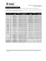
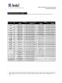
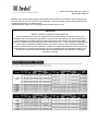
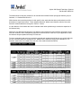
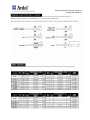
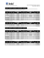
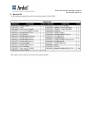
1
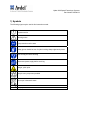
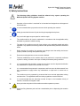
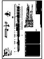
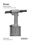
Hydra 1000 Speed Fastening® Systems
Part Number: MA30124
1 Head Hydra 1000
Part Number:
MA30124
Year of
Construction:
2007
Customer:
Various
Manufacturer:
87 Disco Road
Rexdale, Ontario
Canada
M9W 1M3
Phone:
Fax:
Homepage:
416 679 0622
416 679 0678
http://www.avdel-global.com
Hydra 1000 Speed Fastening® Systems
Part Number: MA30124
Table of Contents
1
Symbols
2
Safety Instructions
3
General Liability
4
Manufacturing Contact
5
Operating Instructions
6
Nose Equipment
7
Speed fastening Tool Assembly
8
Priming
9
Preventative Maintenance
10
Troubleshooting Guide
11
Transportation and Storage
12
Waste Disposal
13
Recommended Spare Parts List
14
Additional Information
Hydra 1000 Speed Fastening® Systems
Part Number: MA30124
1) Symbols
The following signs may be used in this instruction manual:
Important notice
Warning notice
Eye protection must be worn
Safety gloves should be worn for jobs involving sharp-edged work pieces
Lock-out/tag-out before working
Disconnect power supply before servicing
Danger, pinch point
Recycle every component possible
Do not put in domestic waste
▲=
Safety signs in accordance with Council Directive 92/58/EEC annex 2 of 24 June 1992
Hydra 1000 Speed Fastening® System
Part Number: MA30124
2) Safety Instructions
The following safety guidelines should be adhered to by anyone operating the
MA30124 Speed Fastening System machine.
1
Operation of the machine is restricted for its intended and designed use with approved
Avdel fasteners.
2
It is recommended that eye protection be worn while operating the machine.
3
Safety gloves should be worn for jobs involving sharp-edged work pieces.
4
Only use Avdel approves spare parts for machine repair.
5
The machine shall at all times be maintained in accordance with the applicable safety
standards to guarantee reliable working.
6
The state of the machine must at all times conform to the applicable health and safety
legislation. Any questions concerning machine and operator safety should be directed to
Avdel.
7
Before starting the machine, the operator must always check that safety devices are
properly installed, working and operationally safe.
8
Ensure that venting devices are not covered or blocked.
9
Technical modifications to the machine that are not performed, or expressly confirmed
by Avdel in writing, will lead to the scope of liability and warranty being restricted.
10
It is recommended that hydraulic components and lines must be depressurized before
any maintenance or repair work is carried out on them.
11
It is recommended that pneumatic components and lines must be disconnected from
the compressed air supply before any maintenance or repair work is carried out on
them.
12
The machine must only operated by personnel that have received appropriate training
and instruction. The applicable health and safety regulations must be observed.
13
It is recommended that this instruction manual be kept in the immediate vicinity of
machine, accessible and legible to staff.
14
15
Never point the tool portion of the machine at another operator or person.
When free firing fasteners point tool into a wastebasket prior to depressing the actuation
device.
Hydra 1000 Speed Fastening® Systems
Part Number: MA30124
3) General Liability
Claims under warranty and liability for personal injury and material damage are excluded if such claims
are due to one or more of the following causes:
-
The machine is not being used for its intended purpose.
-
Incorrect installation, commissioning, operation and maintenance of the machine.
-
Operating the machine in spite of defective, incorrectly installed or non-functioning safety devices
-
Structural alteration without the express confirmation of Avdel
-
Poor monitoring of individual parts subject to wear
-
Incorrect repair or maintenance of the machine
-
Disasters caused by the action of foreign objects
Duty of Owner
The owner of the machine undertakes to
-
Allow only those persons familiar with fundamental health and safety regulations and who have been
instructed in the handling of the machine to work with the machine.
-
Provide the necessary safety clothing for operating staff of the machine
-
Regularly test the safety devices provided on the machine.
-
Ensure that operators read and understand the instruction manual, especially the safety rules and
warning advice.
-
Duty of Operators
The operators of the machine undertake to
-
Observe fundamental health and safety regulations
-
Read the instruction manual, especially the safety rules and warnings, and clarify anything they do not
fully understand
-
Report damage to the machine without delay and stop the machine immediately in the event of danger
Hydra 1000 Speed Fastening® System
Part Number: MA30124
4) Manufacturing Contact Information
The manufacturer of the machine is:
Avdel Canada, a Division of Acument Canada Ltd.,
87 Disco Road
Rexdale, Ontario
Canada
M9W 1M3
Phone: 416-679-0622
Fax:
416-679-0678
Copyrights
Avdel retains the copyright ©privileges of this instruction manual. This instruction manual is intended
solely for the owner and his or her staff. It contains regulations and advice that may not be
-
Reproduced
Published
Passed on in any other form
In whole or in part without expressed written permission of Avdel.
Hydra 1000 Speed Fastening®
Systems Part Number: MA30124
5) Operating Instructions
5.1) Machine Start-up
The following instructions should be followed during machine start up.
1. Place Speed fastening Unit in the assembly location.
2. Connect main air supply (3/8” min inlet size). 80-90 PSI
3. Tool should be supplied with clean, dry air only.
5.2) Machine Operation
The following instructions should be followed when operating the machine.
1.
Raise Eye Guard to disengage tails jaws.
2.
Gently pull on protruded spring(s) to remove mandrel(s).
3.
Remove follower / spring.
4.
Insert rivets (Pod) onto on mandrel.
Slide pointed end of pod onto pointed end of mandrel
5.
Peal off paper
6.
Install follower / spring
Ferrell side of spring towards the pod
7.
8.
9.
Carefully push loaded mandrel through nose assembly.
Set 1/8” gap between face of nose halves and head/flange of the first fastener.
Lower Eye Guard to engage tails Jaws.
Repeat Lines 1 – 9 to Reload
Hydra 1000 Speed Fastening®
Systems Part Number: MA30124
6) Nose Equipment
See attached guide in Additional information.
7) Tool Assembly Drawings & Maintenance
Hydra 1000 Speed Fastening®
Systems Part Number: MA30124
7.1) Dismantling Tool
DISMANTLE TAIL JAWS
•With the aid of Spanners 7900-0522, remove adaptor (24) and ‘Tail Jaw Assembly’ from Tail Jaw Housing (42). The Turret Jaws
(19) will be exposed. Care should be taken not to misplace the Jaws (19).
•Clean and inspect Jaw Housing (45). It will be necessary to remove Jaw Housing only if damaged. To remove Jaw Housing (45)
use Jaw Housing Key 7900-0194 and Spanners 7900-0522.
• Clean all items, inspect and replace if necessary. Re-grease using Molylithium based Grease 7992-00020, and reassemble.
DISMANTLE TAIL JAW ASSEMBLY
• Remove Adaptor (24) and ‘Tail Jaw Assembly’ as described above.
• Remove Adaptor (24) from Front Cylinder (44) using spanners 7900-0522. Remove Banjo (43) and ‘O’ Rings (9).
• With Spanners 7900-0522, remove Turret (22) from Piston Rod (49).
• With Spanners 7900-0522, remove Front Cylinder (44) from Rear Cylinder (28). Remove Front Piston Rod (49) and Piston (26).
Remove Circlip (16) and remove Piston from Piston Rod. Remove ‘O’ Ring (4) from Front Cylinder (44). Remove ‘O’ Rings (7) from
Front Piston Rod (49).
Note: Removal of ‘O’ Rings from internal recesses requires the use of a pointed instrument. Care must be taken not to damage
sealing surfaces. Remove ‘O’ Ring (8) from Piston. Remove ‘O’ Ring (10) from Piston.
• Remove Seal Retainer (30). With Spanners remove front Rear Cylinder (28) from back Rear Cylinder (28). Remove Piston Rod
(27), Circlip (16), Piston (26) and ‘O’ Ring Seals as described above
• Remove Seal Retainer (30). With Spanners, remove back Rear Cylinder (28) from Rear Plug (29). Remove Seal Retainer (30).
Remove Piston Rod, Circlip, Piston and ‘O’ Ring Seals as described above.
• Replace worn or damaged parts as required. Clean all parts thoroughly, lubricate Seals and Cylinder Bores with Molylithium
Grease 7992-00020. Re-assemble in reverse order.
DISMANTLE HYDRAULIC BODY ASSEMBLY
• Using Hex Wrench 7900-0013 remove Button Head Bleed Screws (1) and Seals (6) from Body (38). Allow Hydraulic Oil to drain
from Cylinder Body.
• Using Hex Wrench 7900-0226 remove Barrel Assembly (2,11,13,20,21,23,25,31,32,33,34,35,36 and 37).
• Using Spanners 7900-0434 to prevent the Body (38) from rotating, and with the aid of Spanners 7900-0433 remove Tail Jaw
Housing (42) and Tail Jaw Assembly.
• With Spanners 7900-0522, remove Locknut (46) and Piston Nut (45). Remove Buffer Stops (48).
NOTE: It is important that the same number of Buffer stops removed, are replaced on Assembly.
• Remove Piston (41). Remove Lip Seal (15) and Guidance Tape (39), clean all parts thoroughly, inspect for damage, replace if
necessary.
• Remove Lip Seal (14) and Guidance Tape (40) from Body (38), clean and inspect for damage, replace if necessary.
NOTE: Extreme care must be taken when removing Seals, to avoid damage to Sealing Surfaces.
• Inspect Piston Diameters, Body Cylinder Bore, for wear and damage. Replace Lip Seals and Guidance Tape in the correct
relative positions. Lubricate Seals and Cylinder Bore with Molylithium Grease 7992-00020.
RE-ASSEMBLE HYDRAULIC BODY ASSEMBLY
• Re-assemble in reverse of Dismantling with the aid of Assembly Bullet 7900-0669, positioned on the thread of the Piston (41).
CURSOR
Clean and oil mechanical cursor assembly 5 occasionally with a little light oil.
IMPORT ANT
Check the tool against daily and weekly servicing.
Priming is ALWAYS necessary after the tool has been dismantled and prior to operating.
Hydra 1000 Speed Fastening® Systems Part
Number: MA30124
7.3) BOOSTER MAINTENANCE
Instructions
• The Booster 07005-00514 requires little or no maintenance under normal conditions
• The MPO 30 Hydraulic Oil in Reservoir should be changed periodically if it looks Cloudy or Grey
• Seal Kit 07005-01096 is available from Avdel.
8) Priming
PRIMING
Priming is ALWAYS necessary after the tool has been dismantled and prior to operating. It may also be necessary to restore the full stroke after
considerable use, when the stroke may be reduced and fasteners are not fully placed by one operation of the trigger.
OIL DETAILS
The recommended oil for priming is M.P.O. 30 available in 1 litre (part number 07992-00006).
M.P.O. 30 S A F E T Y D A T A
FIRST AID
SKIN: Wash thoroughly with soap and water as soon as
possible. Casual contact requires no immediate attention.
Short-term contact requires no immediate attention.
INGESTION: Seek medical attention immediately. DO NOT
induce vomiting.
EYES: Irrigate immediately with water for several minutes.
Although NOT a primary irritant, minor irritation may occur
following contact.
FIRE
Suitable extinguishing media: CO2, dry powder, foam or water
fog. Do not use water jets.
ENVIRONMENT
WASTE DISPOSAL: Through authorised contractor to a licensed site.
May be incinerated. Used product may be sent for reclamation.
SPILLAGE: Prevent entry into drains, sewers and watercourses. Soak
up with absorbent material.
HANDLING
Wear eye protection, impervious gloves (e.g. of PVC) and a plastic
apron. Use in well-ventilated area.
STORAGE
No special precautions.
INGREDIENTS/IDENTITY INFORMATION
Proprietary: NO
Ingredient: MINERAL OIL (EXPOSURE REGULATED AS 'OIL
MIST')
Ingredient Sequence Number: 01
NIOSH (RTECS) Number: PY8030000
CAS Number: 8012-95-1
OSHA PEL: 5 MG/M3
ACGIH TLV: 5 MG/M3/10 STEL;9192
PHYSICAL/CHEMICAL CHARACTERISTICS
Appearance And Odor: CLEAR BROWN LIQUID; CHARACTERISTIC
OIL ODOR.
Boiling Point: 300F,149C
Vapor Pressure (MM Hg/70 F): N/A
Vapor Density (Air=1): N/A
Specific Gravity: 0.873
Evaporation Rate And Ref: <1 (N-BUTYL ACETATE=1)
Solubility In Water: 0.1%
Percent Volatiles By Volume: 0%
FIRE/EXPLOSION HAZARD DATA
Flash Point: 470F,243C
Flash Point Method: COC
Lower Explosive Limit: NONE
Upper Explosive Limit: NONE
Extinguishing Media: CO2, DRY CHEMICALS
Special Fire Fighting Proc: WEAR NIOSH/MSHA APPROVED
SCBA AND FULL
PROTECTIVE EQUIPMENT (FP N).
Unusual Fire And Expl Hazards: NONE
REACTIVITY DATA
Stability: YES
Cond To Avoid (Stability): NONE SPECIFIED BY MANUFACTURER.
Materials To Avoid: STRONG ACIDS OR ALKALIS WILL AFFECT
QUALITY.
Hazardous Decomp Products: CO, SO2, WITH INCOMPLETE
COMBUSTION.
Hazardous Poly Occur: NO
Conditions To Avoid (Poly): NOT RELEVANT
Hydra 1000 Speed Fastening® Systems Part
Number: MA30124
8.2) Priming Instructions
PRIMING HYDRAULIC SYSTEM
It is essential for the satisfactory working of the pulling module(s) that there is no air
present in the hydraulic system. The removal of all air from the system is referred to as
priming.
PRIMING STEPS :
•
•
•
•
•
Lower module to the floor
Check oil level at the booster and refill if required
Remove the oil bleed plug and seal from the module
Wait until the oil flows freely from module with no air bubbles present
Replace seal and bleed plug
Routine priming
During normal every day operation it may be necessary to prime
the hydraulic system , i.e. After a module change , if the reservoir
is allowed to run dry or if the hydraulic fitting(s) become loose.
When this is required follow the steps described below.
NOTE: READ THE ENTIRE INSTRUCTIONS BEFORE
ATTEMPTING THIS PROCEDURE
1. Remove the bleed screw and seal from the side of the module and situate a suitable
container by the hole to catch the oil.
2. Trigger (foot valve) the tool and hold it on. Oil will squirt out of the priming hole
very aggressively, so be sure the container is in front of the priming hole. Reducing the
main incoming air pressure (20-25 psi) will lower the rate of speed the oil comes out
of the priming hole.
3. Replace the priming seal and screw.
4. Release the trigger (foot valve) mechanism. Oil will then be drawn from the oil
reservoir.
5. Top up the oil reservoir.
6. Repeat steps 1-5 until clean air free oil comes out of the priming hole.
7. Regulate to proper air pressure upon completion of prime.
Hydra 1000 Speed Fastening® Systems Part
Number: MA30124
9) Preventative Maintenance
Prescribed Action
Inspect mandrels for excessive wear and
straightness. Discard if worn or bent.
Inspect Follower springs for wear/damage.
Discard if worn or bent.
Inspect mechanical cursor. Clean and
lightly oil.
Inspect Hydraulic Fittings for oil leaks.
Inspect air cylinders, valves, airlines, and
connections for leaks.
Visually inspect all aspects of tooling for
wear and/or damage. Replace or repair as
required.
Ensure regulator is set to 80-90 PSI.
Ensure Oil reservoir is minimum 1/2 full.
Remove and clean Tail Jaw Assembly
Inspect Front Jaws for wear/damage
Daily
Weekly
Monthly
√
√
√
√
√
√
√
√
√
√
Hydra 1000 Speed Fastening® Systems Part
Number: MA30124
10) Troubleshooting Guide
Fault
Excessive Tail Jaw Wear
Possible Cure
•
•
•
Mandrel Slipping in Tail Jaws
•
•
•
•
Double Feeding
Not Feeding Rivets
•
•
•
•
•
Incomplete stroke of module
•
•
•
•
•
Ensure correct nose equipment has been
selected for the fastener and hole
combination
Check for air leaks and ensure correct air
pressure and volume is available
Ensure correct rivet has been selected for
the grip range being fastened
Check for wear on Tail Jaws. Replace if
necessary.
Check to ensure sufficient volume and
pressure of air supply is maintained.
Ensure there are no air leaks to the Tail
Jaws
Ensure Tail Jaw operating valve is
switching
Check for Mandrel Slip
Check nose equipment for proper assembly
Ensure the correct gap is set between rivet
head and tip of nose jaws.
Ensure the cursor is installed properly.
Clean and lightly oil mechanical cursor
assembly.
Evaluate follower spring
Check nose equipment compatibility.
Weak / Worn cursor collar
Speed fastening Module(s) requires
priming. See priming instructions.
Low air pressure and/or volume
Hydra 1000 Speed Fastening® System
Part Number: MA30124
11) Transport and Storage
Transportation Data
The machine’s dimensions and weight can be found under machine technical specifications.
Loading and unloading
Do not tilt the machine during transport, loading and unloading. Observe the laws and
instructions valid for your country when transporting hazardous substances.
The machine is supplied with suitable transit packing; a forklift truck of sufficient lifting capacity for the gross
weights (Â Specifications) is required to unload the system and transport it to the operational location.
Carefully remove all the transit packaging from the system.
The customer is committed to check the entire equipment as delivered for signs of
damage. If any damage is determined, it must be reported immediately to Avdel.
If damage is found, it must be documented (e.g. by photograph) to help render any description thereof more
comprehensible.
Storage
A dry location should be chosen for temporary storage of the machine. Depending on the storage time,
sensitive parts must be preserved and protected against soiling.
17
Hydra 1000 Speed Fastening® System
Part Number: MA30124
12) Waste Disposal
For any kind of waste disposal, please observe the applicable national laws and regulations. Please consider
the following.
Recycle every component possible
Do not put batteries in domestic waste
WASTE DISPOSAL
The various components of the machine must be disposed of separately. First remove fuel and oil from the
machine.
Hydraulic oil presents a hazard to ground water. Uncontrolled draining or incorrect
disposal is liable to prosecution (environmental liability law).
Batteries and accumulator must be disposed of in accordance with special laws and regulations.
Batteries and accumulator must be treated separately from other waste and must not be
put in domestic waste. Contravention is liable to prosecution.
The other components of the machine must be disposed of in accordance with applicable national laws and
regulations.
Because of potential environmental damage, we recommend that a professional company dispose of the
machine. The old machine cannot be returned to the manufacturer free of charge.
ADDRESSES
For any questions concerning waste disposal please contact
Environment Canada
351 St. Joseph Boulevard
Hull, Quebec
K1A 0H3
Or consult your regional waste management body.
Hydra 1000 Speed Fastening® System
Part Number: MA30124
13) Recommended Spare Parts List
Item
AVDEL #
Description
Rec. Spares
Nose Equipment
78901-100041 Booster (25:1) Sub Assembly
2
6
7
07005-00344
07992-00006
0L500-00007
Silencer
MPO 30 Hydraulic Oil
Oil Seal
1
2 liters
1
78901-010047 70500 Module Sub Assembly
1
5
6
0L400-00021
0L500-00007
70500-02000
Pneumatic Elbow
Oil Seal
Speed fastening Module
2
1
1
70500-02000 Module Assembly
Item
1
5
6
14
15
19
20
25
36
39
40
48
AVDEL #
Description
07003-00114 10-24 UNC Button Head Screw
07003-00028
O Ring Seal
07003-00033
Bonded Seal
07003-00242
Hydraulic Seal
07003-00243
Hydraulic Seal
07151-00403
Turret Jaw (set)
07271-01100
Cursor
07003-00036
O Ring Seal
70500-02004
Spring
70500-02007
Piston Guide Tape - Long
70500-02008
Piston Guide Tape - Short
70500-02016
Buffer
Recommendation Quantities based on a 3 Head System
Rec. Spares
2
4
4
4
4
4
1
4
1
2
2
2
Hydra 1000 Speed Fastening® System
Part Number: MA30124
14) Additional Information List
1. Maintenance and Repair
The machine must be secured against being switched back on before any
maintenance or repair work is carried out! (E.g. locked out)
Specialized and trained staff must do maintenance or repair work!
2. Nose Equipment and Mandrel Selection Guide
Hydra 1000 Speed Fastening® Systems
Part Number: MA30124
Choosing a Nose Jaw Assembly
1. List the name, size and material of the fastener to be placed.
2. Look for this fastener in the first column of the nose jaw selection tables listed below. Use the
appropriate table for imperial or metric units.
3. Looking right across the table take note of which nose jaws are available. ONLY those shown are
available.
4. Select which is most suitable for your application by referring to the respective nose jaw drawing. If
your application has no access restriction, you should select the standard shape with a flat end form
with or without cam operation.
Hydra 1000 Speed Fastening® Systems
Part Number: MA30124
Hydra 1000 Speed Fastening® Systems
Part Number: MA30124
Hydra 1000 Speed Fastening® Systems
Part Number: MA30124
Hydra 1000 Speed Fastening® Systems
Part Number: MA30124
Hydra 1000 Speed Fastening® Systems
Part Number: MA30124
Hydra 1000 Speed Fastening® Systems
Part Number: MA30124
Mandrels and mandrel follower springs (see illustration above) need to be selected to suit the fastener type
and size as well as the size of the hole in the application. Use of the wrong mandrel could increase the risk
of breakage and wear of the mandrel head.
Feeding problems could occur if the wrong mandrel follower spring is used.
IMPORTANT
READ THE SAFETY INSTRUCTIONS CAREFULLY.
While a small amount of wear and marking will naturally occur through normal and correct use of
mandrels, they must regularly be examined for excessive wear and marking, with particular attention to
the head diameter, the tail jaw gripping area of the shank for heavy pitting of the shank and mandrel
distortion. Mandrels which fail during use could forcibly exit the tool. It is the customer’s responsibility to
ensure that the mandrels are replaced before any excessive levels of wear and always before the
maximum recommended number of placings. Contact your Avdel® representative who will let you know
what that figure is by measuring the broach load of your application with our calibrated measuring tool.
These tools can also be purchased under part number 07900-09080, supplied with all necessary
information for testing.
Hydra 1000 Speed Fastening® Systems
Part Number: MA30124
The tables below list the part numbers for all mandrels and mandrel follower springs per fastener group of
fasteners, i.e. Chobert® and Grovit ®
While fastener sizes are always shown in their specific units, each table has been produced twice to offer
dimensions in imperial and metric. These “Mandrel Selection” tables cross reference with the “Nose Jaw
Selection” tables listed above through the “Ref No.” column.
It is the diameter of the head at the end of a mandrel which when pulled through controls the expansion of
the fastener body.
While there are different head shapes to suit different types of fasteners (see illustration) progressive head
sizes are needed to reflect manufacturing tolerances on the diameter of the hole in your application so that
the fastener always expands sufficiently to fill the hole.
Too large a mandrel head would over stress the mandrel and mandrels that fail during use could forcibly exit
the tool. Selection tables are arranged in four “Mandrel Size” selections ranging from “Standard” to “3rd
Oversize” each being color coded as per the end of the mandrel heads themselves.
Hydra 1000 Speed Fastening® Systems
Part Number: MA30124
Choosing a Mandrel
Hydra 1000 Speed Fastening® Systems
Part Number: MA30124
Hydra 1000 Speed Fastening® Systems
Part Number: MA30124
below
Hydra 1000 Speed Fastening® Systems
Part Number: MA30124
Hydra 1000 Speed Fastening® Systems
Part Number: MA30124
3. Service Kit