1
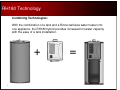
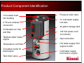
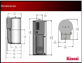
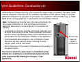
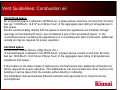
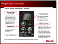
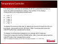
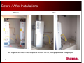
Rinnai RH180 Hybrid Tank –
Tankless Water Heater
Product Knowledge, Level I
1
Rinnai Service and Support (800-621-9419)
CRC – Consumer Response Center – general calls, consumer questions, etc.
Available from 8 a.m. to 8 p.m. EST, Monday – Friday.
Parts Department – parts orders.
Available from 8 a.m. to 8 p.m. EST, Monday – Friday.
Warranty Department – warranty claim issues.
Available from 8 a.m. to 5 p.m. EST, Monday- Friday.
Technical Support Department – technical issues related to the function and repair of all
Rinnai products.
Available in the office from 8 a.m. to 8 p.m. EST, Monday – Friday AND 24/7/365 on call support for
technicians who are at the service location. Technicians only, call 1-888-RINNAIS ( 888-746-6247)
Engineering / Applications Department – calls related to product use and applications
including sizing.
Available from 8 a.m. to 5 p.m. EST, Monday - Friday.
Rinnai America also provides the following websites for support:
• www.rinnai.us –for installation manuals, product specifications and supporting documents. More technical information
is available in the “For Professionals” section of the site under “Partner Portal”. Registration is required for access to
this portion of the website.
• www.trainingevents.rinnai.us – for registration in Rinnai product training classes and videos (live and online classes).
Service and installation manuals and other technical documents are available under the “Resources” section of the site.
RH180 Hybrid Tank-Tankless Water Heater
Level I Training Program
Product Knowledge
3
RH180 Technology
Combining Technologies:
With the combination of a tank and a Rinnai tankless water heater into
one appliance, the RH180 hybrid provides increased hot water capacity
with the ease of a tank installation.
+
4
=
Product Component Identification
• ¾ hot water feed
into building
• 4” B-vent exhaust
connection
• Combustion air inlet
and filter
• Pressure relief valve
• ¾” cold water supply
into tank
• 40 gallon storage tank
• 120 Volt power cord
(not shown)
• Tankless water heater
engine
• Gas connection
• Temperature controller
• Hot water supply from
engine to tank
• Circulation pump for
tank/engine
• Tank drain valve
5
• Cold water supply
from tank to engine
RH180
Sequence of Operation
6
Sequence of operation:
1. When the water temperature at the bottom of the tank (at the tank
thermistor) drops to a pre-determined temperature, the startup
sequence will begin.
8.
2.
2. The tankless engine’s combustion fan will begin turning, drawing
fresh air from the space. This will allow the flammable vapor sensor
to ensure the intake air is free of combustible vapors.
4.
3. The pump will begin circulating water through the tank-tankless
loop.
4. The engine will fire when it detects the water flow from the pump.
5.
5. The heated water from the engine will be deposited back into the
tank. The water will be directed toward the top of the tank close to
where hot water is being drawn into the plumbing system.
3.
6. Initially as water is drawn from the tank into the engine, the Delta T
will be fairly large and the engine will operate in a high fire mode.
6.
7.
7. As the water at the bottom of the tank begins to heat, warmer
water will then begin to enter the engine — this will reduce the
Delta T allowing a higher flow rate through the engine.
1.
8. As the water in the tank continues to warm and gets closer to the
set temperature, the tankless engine will automatically reduce its
gas input.
9.
9. When the temperature at the bottom of the tank reaches the set
point, the pump turns off — the tankless engine will go into a
standby mode until the next start sequence.
7
RH180
Water Heater
Sizing
8
RH180 Sizing
Water Heating
Options
Max input (Btuh
/ Kwh)
Tank Capacity
(gal.)
Showers In use
at one time
Electric Tank
Gas Tank
Time of available
hot water (min.)
Time of available
hot water (min.)
70⁰ temp rise
70⁰ temp rise
Recovery time
(min.)
70⁰ temp rise
4.5 Kw
40
21
10
88
34,000 Btu
40
18
8
36
40,000 Btu
50
26
11
40
75,000 Btu
75
50
19
32
91,300 Btu
40
Continuous
11
16
Up to 199,000
Btu
N/A
Continuous
Continuous
N/A
Rinnai RH180
Hybrid
Tank -Tankless
Rinnai Tankless
• Data is based on a 50⁰F inlet water temperature and a 120⁰F hot water set point (70⁰F rise).
• Shower heads assumed to be 2.5 gpm mixed flow rate with 105⁰F at the fixture.
• Available hot water time and recovery time based on industry standard calculation methods
and Rinnai lab testing. Actual results may vary based on the application.
RH180
Product Features &
Safety devices
10
Product Features
• 180 gallon First Hour Rating.
• Quick recovery: Approximately 16 minutes starting from a cold tank.
• Thermal Efficiency: 80%.
• Temperature controller: 5 temperature settings.
• Maintenance/diagnostic codes: Error codes displayed if a fault is detected.
• 40 gallon storage tank: Two inches of insulation, no heating element, burner, or
vent stack which helps to minimize standby heat loss.
• Direct electronic ignition: No standing pilot.
• Blue-zircon-glass coated tank.
• Uses standard 4” B-Vent.
• Can be common vented with a furnace.
• Piping configuration and connections same as standard tanks.
• 1/2” gas line connection.
• Water is heated in the engine not the tank: Less thermal stress on the tank.
11
• Circulation system compatible.
Safety Devices
• Flame rod: Detects when flame is present or is extinguished.
• Overheat bi-metal sensor: Detects overheated water conditions.
• Boiling protection sensor: Monitors heat exchanger water temperature.
• Heat exchanger thermal fuse: Detects heat exchanger overheat condition.
• Burner/combustion fan sensor: Indicates if there is a blocked flue.
• Flammable vapor sensor: Monitors for flammable vapors in intake air supply.
• CO sensor: Monitors exhaust gasses for poor combustion, (NOTE: not a room CO
sensor).
• Built in surge protector.
• Power supply is protected by 5-amp glass fuse.
• Main circuit board monitors component operation and will post error codes or
maintenance codes on the temperature controller if abnormal operation is detected.
12
Specifications
Model
13
RH180
Min / Max Gas Input Rates
Min. 59,500 Btu-Natural Gas / 47,600 Btu-Propane
Max. 91,300 Btu-Natural Gas / 87,300 Btu-Propane
(two stage burner, does not modulate between max-min inputs)
First Hour Rating
180 Gallons / hour
Storage Tank Volume
40 gallons
Temperature Selections
110⁰F, 120⁰F, 130⁰F, 135⁰F, 140⁰F (43⁰C, 49⁰C, 54⁰C, 57⁰C, 60⁰C )
Weight
150 lbs. (68kg)
Thermal Efficiency
80%
Noise Level
50 dB
Electrical
120 VAC, 60 Hz. , Normal Operation - 150 watts / Standby – 3 watts (5 amp
fuse)
Minimum Gas Supply Pressure
4.0” w.c. Natural Gas / 8.0” w.c. Propane
Maximum Gas Supply Pressure
10.5” w.c. Natural Gas / 13.5” w.c. Propane
Connections
Gas Supply: ½” MNPT – Water Connections: ¾” MNPT
Water Supply Pressure
20 - 150 psi (Recommend 30 – 50 psi for maximum performance)
Sensor and Switches
Flammable Vapor, Combustion Air CO Sensor, Bi-Metal Overheat Switch
See Operation / Installation manual for more complete information. Specifications subject to change without prior notice.
RH180
Installation
Requirements
A licensed professional must install the appliance, inspect it and leak test it before use. The
warranty may be voided due to improper installation.
The installer should have skills such as:
• Gas sizing
• Connecting gas lines, water lines, valves and electricity.
• Knowledge of applicable national, state and local codes.
• Installing venting through a wall or roof.
• Venting Category I, Fan Assist Appliances per NFPA 54 and local codes.
14 If you lack these skills contact a licensed professional.
Installation Location
•
Not approved for mobile homes or outdoor installations (can be used in light commercial
applications where the temperature requirement do not exceed 140⁰ F).
•
Installation must be accomplished in such a manner that if the tank or any connection
should leak, the flow of water will not cause damage to the structure. For this reason it is
not advisable to install the water heater in an attic or upper floor. When such location
cannot be avoided, an approved drain pan should be used and piped to a drain line or
outside the home.
•
Use an approved tank water heater drain pan. (Rinnai recommends 26” diameter pan) See
International plumbing code for details.
•
Gasoline or other flammable substances MUST NOT be stored in the vicinity of the water
heater.
•
A stand is not required as this water heater complies with the FVIR requirements and the
burner and igniter are positioned greater than 18 inches from the base of the unit (verify
with local codes).
•
If installed in a crawl space with a dirt floor, position the unit on a solid level surface (such
as concrete) away from the ground’s moisture.
•
If installed in a closet or alcove, ensure all intake (combustion) air requirements are
followed, see owner’s/installation manual.
•
The RH180 meets or exceeds the National Appliance Energy Conservation Act Standards
with respect to insulation and standby losses. If an insulation blanket is still desired, follow
the installation procedures outlined in the Operation and Installation manual.
15
Dimensions
16
Electrical and Water Installation
Code Adherence
- Installation MUST comply with National, State, and Local codes.
Electrical Requirements
-
Standard three-prong 120 VAC, 60 Hz. grounded circuit.
-
Ensure plumbing lines are grounded in accordance to Local, State, and National codes.
Water Installation Requirements
- Supply pressure 20 – 150 psi.
-
A temperature/pressure relief valve is supplied with the product. The discharge must be
piped per local code requirements.
-
Water quality should meet Part 143 of the National Secondary Drinking Water Regulations.
(see installation manual for guidelines).
-
Ensure inlet water filter on appliance is clean before filling tank.
-
Do not operate water heater unless tank is completely full of water.
17
RH180
Venting
and
Altitude Requirements
! WARNING
Improper installation of the vent system and its components, or failure to follow all installation instructions,
can result in property damage or serious injury
18
Vent Guidelines: Combustion air
Combustion air is drawn from the room in which the water heater is installed. This water heater
requires adequate combustion air for ventilation and dilution of flue gasses. Failure to provide
adequate combustion air can result in unit failure, fire, explosion, serious bodily injury or death.
Read all the venting guidelines in the Operation and Installation manual.
Note: Combustion air must be free of corrosive chemicals. Do
not provide combustion air from corrosive environments.
Appliance failure due to corrosive air is not covered by the
warranty.
• Combustion air must be free of acid forming chemicals such
as sulfur, fluorine and chlorine. These chemicals have been
found to cause rapid damage/decay and could become toxic
when drawn into the combustion chamber of the appliance.
• Such chemicals can be found in, but not limited to bleach,
ammonia, cat litter, aerosol sprays, cleaning solvents,
varnish, paint, and air fresheners.
• Do not store any of the products listed above in the vicinity of
this water heater.
The room in which the water heater is installed must be
defined as a confined or unconfined space based on the
code requirements pertaining to Category 1 type
appliances.
Air from the
space is
used for
combustion
Vent Guidelines: Combustion air
Unconfined space:
An unconfined space is defined in NFPA 54 as “a space whose volume is not less than 50 cubic
feet per 1,000 Btu/hr. (4.8 m3 per kW per hour) of the aggregate input rating of all appliances in
that space.
Rooms communicating directly with the space in which the appliances are installed, through
openings not furnished with doors, are considered a part of the unconfined space”. If the
“unconfined space” containing the appliance(s) is in a building with tight construction, additional
outside air may be required for proper operation.
Confined space:
(Small room, Closet, Alcove, Utility Room, Etc.)
A confined space is defined in the NFPA 54 as “a space whose volume is less than 50 cubic
feet per 1000 Btu/hr. (4.8 m3 per kW per hour) of the aggregate input rating of all appliances
installed in that space”.
If the location of the water heater is defined as a confined space then additional combustion air
will be required for proper operation. This additional air can be provided from other rooms in the
building or can be taken from the outside (either directly or indirectly).
The installation manual illustrates different methods and requirements on how this can be
accomplished.
Vent Guidelines: Exhaust
• This water heater must be vented/terminated vertically to the outside of the building or structure. This water
heater is NOT designed or certified for side wall horizontal vent terminations.
• Vent or vent connector runs should be as short and direct as possible.
• It is not permitted to reduce vent diameter (4”).
• All installations must be vented in accordance with the National Fuel Gas Code NFPA 54/ANSI Z223.1 –
latest edition and the requirements of State or local codes. In Canada, the furnaces must be vented in
accordance with National Standard of Canada, CAN/CSA B149.2 – latest editions and amendments and the
codes of the local utility or other authority having jurisdiction.
• The RH180 CANNOT be vented into any chimney serving an open fireplace or any other solid fuel burning
appliance.
• The RH180 can ONLY be connected to a manufactured chimney or vent that complies with a recognized
standard. Venting into a masonry or concrete chimney is only permitted as outlined in the NFPA54/ANSI
Z223.1 National Fuel Gas Code venting tables. It is therefore a contractual obligation on the part of the
installer to follow all safe venting requirements.
• Existing exhaust vent or chimney is to be checked to ensure they meet clearances and local codes.
High Altitude Installations
Set dip switch 3 to the position shown in table below for your altitude. The default setting for the
appliance is 0 – 2,000 ft. (0 - 610 meters) with dip switch 3 in the OFF position. The maximum
allowed altitude for this appliance is 5,400 ft. (1,646 meters).
0 – 2000 ft.
(0- 610 m)
2001 – 5400 ft.
(610 – 1646 m)
Dip switch 3 in
the bank of 8
switches will
adjust the unit
for altitudes of
2001- 5400 feet
WARNING: Do not adjust the other dip switches unless specifically instructed to do so.
22
RH180
Gas Supply Installation
When sizing a gas system you MUST take into account the type pipe and gas being used, the
inlet gas pressure being fed to the site, meter, regulator and/or tank size and Btu ratings.
Improperly sized gas system will result in poor performance of all gas appliances.
23
Gas Installation
The RH180 has a maximum input of 91,300 Btu. Under most circumstances the same supply gas
line that supplies a standard atmospheric tank water heater (40 gallons or more) will adequately
supply the RH180. Consider the following:
• All gas appliances in the structure MUST be included in gas sizing calculation.
• Flexible gas supply lines connected directly to the RH180 MUST be able to supply a minimum
of 91,300 Btu for NG or 87,300 Btu for LP.
• Consult the NFPA 54 National Fuel Gas Code Pipe Sizing Guidelines to ensure adequate gas
supply is provided.
• Supplied gas pressure must be within the recommendations listed on the unit’s rating plate.
• The RH180 requires a higher gas supply than standard 40 gallon tank water heaters.
-
The RH180 has a maximum input rating of 91,300 Btu (natural gas models).
-
The average 40 gallon gas-fired tank water heater has an input rating of approximately 40,000 Btu.
-
In this example, the difference between the RH180 and the 40 gallon tank water heater is 51,300 Btu.
This additional gas load must be considered when installing this product.
• Issues caused by insufficient gas supply:
- Poor appliance operation or intermittent error codes.
- Rumbling noises due to insufficient air/gas mixture.
If any symptom exists suggesting a gas supply issue may be present, a gas manometer will be needed to
verify incoming pressure.
RH180
Temperature
Controller
25
Temperature Controller
26
Temperature Controller
Five temperature settings are available. Push the up and down arrows to
select the desired temperature setting. The number on the display
corresponds to the temperature scale below.
1.
2.
3.
4.
5.
= 110°F
= 120°F
= 130°F
= 135°F
= 140°F
To display the recovery flow rate (in gallons per minute) through the unit (not
the fixture), press and hold the UP button. After 3 seconds also press the
ON/OFF button then release both buttons.
To display the temperature supplied to the storage tank in degrees
Fahrenheit, press and hold the DOWN button. After 3 seconds also press the
ON/OFF button then release both buttons.
(Note: the temperature display will be one or two digits, Example: 14 = 140 to 149.
27
RH180
Maintenance
and
Warranty
28
Maintenance – Inlet Water Filter
• Rinnai recommends that the inlet
water filter be cleaned before the
initial operation of a new unit.
• Before removing the inlet filter,
ensure that the water supply has
been turned off.
• If the tank is already full, it must be
drained from the drain valve at the
bottom of the tank.
• See filter location in picture at right.
• Remove any debris from the filter
either by rinsing or low pressure
compressed air.
• When reinstalling the filter assembly,
it should be hand tightened only.
29
Maintenance – Intake air filter
•
The RH180 is a fan assisted
water heater. Intake air is
drawn into the appliance from
the surrounding area.
•
To maintain optimum
performance, periodically clean
the air filter. Do not operate unit
if the filter is not in place.
•
A dirty air filter could result in
codes 05, 10 or 13 being
posted on the temperature
control panel. See manual for
details.
30
Maintenance - Tank
• Drain the water from the tank at least once per year. This will remove excess
sediment from the bottom of the tank. Accumulated sediment will reduce the
efficiency and life expectancy of the tank.
• Manually operate the relief valve at least once per year.
• The water heater is equipped with an anode rod that is designed to prolong the
life of the glass-lined tank. This anode is slowly consumed protecting the tank
from corrosion. The anode should be checked every two years. If more than
half of the anode has been consumed it should be replaced.
• In certain conditions, the anode rod can react with the water producing
discolored water or an odor. This can be a result of the reaction between the
anode and hydrogen sulfide gas dissolved in the water. For more information
see the “required maintenance” section of the operation and installation manual
under “Anode”.
31
Maintenance – Engine Heat Exchanger
• Flushing the heat exchanger consists of
pumping virgin food grade white
vinegar or food grade citric acid through
the copper heat exchanger to remove
lime scale or calcium buildup.
• Damage caused by lime or scale
buildup is not covered under the water
heater’s warranty.
• Specific flushing instructions can be
found in the System Maintenance
section of the operation and installation
manual.
5 gallon bucket to be filled
with 4 gallons of food grade
white vinegar or citric acid.
32
Maintenance Codes (specific to RH180).
Maintenance codes flash on the temperature controller when a fault occurs.
Depending on the code, water flow or power may need to be reset to clear the code.
See owner's manual for a full detailed list of all codes.
Diagnostic Codes and Remedies
Some of the checks below should be performed by a licensed professional. Consumers
should never attempt any action that they are not qualified to perform.
Code
Definition
Remedy
05
Air Filter Error.
Follow the procedure “Air Screen Inspection, Detection and Cleaning” in the
operation / installation manual. If the error code continues to flash after
cleaning the air filter, review the items under “Code 10” or contact a qualified
service technician.
NOTE: This code will allow the water heater to continue operating.
07
Circulation flow
rate has dropped
below 2.1 GPM.
Check the water filter for blockage.
Check pump operation and wiring.
Clean heat exchanger.
NOTE: This code will allow the water heater to continue operating.
13
Combustion.
Review items listed under codes “05” and “10”.
33
Maintenance Codes (specific to RH180).
Code
Definition
FE
Cont.
Flammable Vapors
Detected.
Licensed
Professional
Only
When safety personnel have identified the area as safe and all flammable
vapors have been removed and eliminated, the water heater can be reset by
unplugging the unit and then plugging back in.
If “FE” continues to flash after the area is determined to be free from
flammable vapors, contact a qualified service technician.
30
FV sensor
(flammable vapor)
Licensed
professional
only
Check sensor wiring for damage.
Measure resistance of sensor.
Replace sensor.
35
Tank temperature
thermistor.
Licensed
professional
only
Check sensor wiring for damage.
Measure resistance of sensor.
Verify that sensor is properly mounted on the tank surface.
Replace sensor.
38
CO or FV sensor.
Licensed
professional
only
Check sensor wiring for damage.
Measure resistance of sensor.
Replace sensor.
63
Circulation flow
rate has dropped
below 1.3 gpm.
34
Remedy
Licensed
professional
only
Check water filter for blockage.
Check pump operation and wiring.
Clean heat exchanger.
Maintenance Codes (specific to RH180).
Code
Definition
Remedy
NO
Code
No hot water, no
light or error code
on temperature
controller display.
Confirm the water heater is plugged in and has 120 VAC available.
Confirm the water heater is turned on at the temperature controller.
Since the hot water supply to the building comes from the tank and not directly from the
tankless engine, opening a fixture will not flow water through the engine and will not
automatically trigger it to fire.
•
The tankless engine will fire only when it detects water flow and since the flow is
provided by the built in circulation pump, no code or operation could be the result of the
pump not turning on. The issue could be the pump is not being commanded to turn on. If
the tank thermistor is faulty or damaged and not reading the correct temperature, it may
not be triggering the pump to turn on.
•
If the pump is being signaled to turn on and the unit is not sensing flow (due to the pump
not operating or not flowing water or due to a damaged flow turbine, flow sensor,
disconnected flow sensor, or clogged filter) you should get a code 63 since the flow
reading would be “zero”. Code 63 is posted if the flow rate is below 1.3 GPM.
35
Internal view of tank
¾” cold feed inside tank
¾” anode rod inside tank
¾” circulation pump feed line
back into tank
Bottom pan of tank
36
Piping – Typical Installation
Typical Installations.
A
Hot Water Outlet
*
I
Combustion Air Screen
B
Hot water Outlet Valve
*
J
C
Temperature – Pressure
Relief valve
Operation Unit /
Temperature Control
K
Outlet Receptacle
*
Drain Pan
*
D
Cold and Hot Unions
*
L
E
Cold Water Supply valve
*
*
F
Cold Water Supply
*
G
Thermal Expansion Tank
*
M Temperature – Pressure
Relief Valve Discharge
Pipe (do not cap plug or
reduce)
H
4” B-Vent
*
N
Drip Leg (Sediment Trap)
*
O
Gas Union
*
P
Gas control valve
Q
Thermostatic Mixing Valve
*
R
Non-Tempered Return
Line
*
S
Non-Tempered Supply
Line
*
Mixing Valve Installation
* Field Supplied
37
Installation Method (2 units)
Pictures are for illustration Purposes only.
Parallel Piping (recommended method)
Hot water out
Cold water in
Series Piping (not allowed)
38
Drip pans MUST be installed under each water heater
per local or State code,
Warranty
How long does warranty coverage last?
Period of coverage (from date of purchase)
Item
Single family Residential
applications.
Commercial applications
Domestic hot water only
Combination domestic hot water / space
heating and all other applications. [3]
Heat Exchanger
10 years [1]
5 years [2]
3 years
Tank
6 years [1]
1 year
1 year
All other parts and
components
3 years [1]
3 years
3 years
Reasonable labor.
1 year
[1] For residential applications the period of coverage is reduced to 3 years on the heat exchanger and one year on the tank from date of purchase when
used as a recirculating water heater within a hot water recirculation loop, where the water heater is in series with a recirculation system and all
recirculating water flows through the water heater, and where an aquastat / thermostat, timer or an on-demand recirculation system is not incorporated. A
system that incorporates a continuous recirculation due to timer settings, excessive heat loss of the loop or aquastat / thermostat setting will be treated as
a continuous recirculation system and have a reduced warranty of 3 years on the heat exchanger and 1 year on the tank.
On-demand recirculation is defined as a hot water recirculating loop or system that utilizes existing hot and cold water lines or a dedicated return line and
only activates when domestic hot water is used.
[2] Commercial applications incorporating any type of recirculation have a reduced warranty period of 3 years on the heat exchanger.
[3] Domestic hot water must be heated directly within the water heater. When combined with domestic hot water production the water heater may be
connected to provide space heating either directly or indirectly for distributing heated fluid to either a fan coil or similar appliance for space heating
purposes.
39
RH180
FAQ
40
FAQ
1.
Is the engine available separately?
• No, because the minimum input is 60,000 Btu, ignition occurs at no less than 2 gpm-this is not a viable stand alone
tankless product
2.
Is this product ENERGY STAR rated?
• No, currently there is no qualification for tank water heaters over 75,000 Btu
3.
What is the energy factor rating?
• Energy factor ratings are only assigned to tank water heaters with 75,000 Btu or less
4.
Is this product eligible for any federal tax credits or incentives?
• Not at this time. The efficiency is compliant but the Btu for a tank must be less than 75,000 to qualify as a residential
water heater
5.
What happens if the demand is great enough to deplete the tank?
• If demand is 3 gpm or less, the engine will service the demand adequately. So, the unit can provide an endless supply of
hot water supply to a single standard shower or washing machine, etc.
• If demand is greater than 3 gpm, after the tank is depleted of its stored hot water, there could be a reduction in
temperature—this will be dependent on the flow and groundwater (supply) temperature.
• It is important to note that full recovery with no demand is only about 15 minutes.
6.
Does the controller beep when there is an error code?
• No.
41
FAQ (continued)
7.
Is this product approved for commercial use?
• Yes - light commercial use. Maximum temperature is 140°F.
8.
Is this product approved for circulation? If so, how is the warranty affected?
• Yes, circulation can be applied to this system in the same manner as a normal tank. The warranty may be reduced to 3
years on the heat exchanger and 1 year on the tank depending on the type of circulation used. See product warranty for
details.
9.
Can drain down solenoid valves be installed?
• Due to the design, this would drain the entire tank, which would not be viable.
10. Are there any high altitude stipulations?
• Installation are permitted up to 5,400 ft. only. Installations between 2,001 and 5,400 feet require a dip switch adjustment.
11. What is the material of the tank?
• Carbon-steel glass lined tank. The glass lining reduces corrosion issues.
12. Can multiple RH180 units be installed together?
• Yes. No additional equipment (such as MSA control accessories) is required. They should be installed with balanced
parallel piping.
13. What are the makeup air requirements of the RH180?
• Please see the installation manual for the appropriate room calculation procedures to determine this.
42
RH180
Residential
Applications
43
Before / After Installations
Before
After
Three, 40 gallon tank
water heaters (2-gas,
1-electric) servicing a
5,000 sq. ft. home
The gas units were
common vented with
a furnace.
No change to the
existing vent was
required to install the
RH180.
The RH180
sufficiently replaced
all three tanks.
44
Before / After Installations
Before
After
40 gallon gas
tank water
heater common
vented with
existing furnace.
No change to
existing vent was
required beyond
junction point.
45
Before / After Installations
Before
After
No change to existing
vent beyond junction
point.
40 gallon gas tank
water heater common
vented with furnace.
46
Before / After Installations
Before
After
40 gallon gas natural
tank. Venting was
changed to 4” using the
same roof flashing and
penetration
47
Before / After Installations
Before
After
Two 40 gallon tank water heaters replaced with one RH180, freeing up valuable storage space
48
This concludes the
RH180 Water Heater
Training Program Level I
Product Knowledge
401101 (12/2013)
49