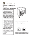
1
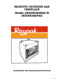
MAJESTIC OUTDOOR GAS
FIREPLACE
Model: ODGSR36ANAU &
ODGSR36APAU
Installation and Operating Instructions
Page 1 of 18
CONTENTS
Part 1:
For Your Safety
Part 2:
Installation Instructions
•
•
•
•
•
•
•
•
•
•
•
•
•
General Information
Fireplace Dimensions
Clearance to Combustibles
Mantels
Mantel Chart
Hearth
Framing and Finishing
Final Finishing
Gas Specifications
Gas Inlet and Burner Pressures
High Elevations
Valve Access
Gas Fitting Line Installation
Part 3:
•
•
•
•
•
•
•
Operating Instructions
Log Installation
Lava Rock
First Firing
Flame Adjustment
Flame Characteristics
Lighting and Operating Instructions
Troubleshooting
Part 4
Maintenance
Part 5
Replacement Parts
Part 6
Warranty
Page 2 of 18
Part 1: For Your Safety
For your safety do not operate this appliance before reading this instruction
book.
WARNING: Improper installation, adjustment, alteration, service or
maintenance can cause injury or property damage. For assistance or
additional information consult with Raypak Australia, your Raypak
distributor, qualified installer or accredited Rheem Australia Service agency.
WHAT TO DO IF YOU SMELL GAS?
DO NOT try to light any gas appliance.
DO NOT touch any electrical switch.
Turn off gas supply at meter.
Immediately call Rheem Service or your gas supplier or licensed gas fitter.
Note: Some gases are heavier than air and it maybe necessary to check for gas leaks
at floor level.
CAUTION!
DO NOT operate this appliance before reading this instruction booklet.
DO NOT place articles or objects on or against the appliance.
DO NOT store chemicals or flammable materials near this appliance.
DO NOT spray aerosols in the vicinity of this appliance whilst it is in operation.
PRIMARILY A DECORATIVE APPLIANCE – NOT CERTIFIED AS A SPACE HEATER.
TO REDUCE THE RISK OF FIRE OR INJURY FROM BURNS AND FOR THE PROTECTION
OF YOUNG CHILDREN OR THE INFIRM, A SECONDARY GUARD IS RECOMMENDED.
Page 3 of 18
GENERAL INFORMATION
FOR SAFE INSTALLATION AND OPERATION OF YOUR GAS APPLIANCE
PLEASE NOTE THE FOLLOWING:
a) This appliance gives off high temperatures and should be located out of high traffic
areas and away from outdoor furniture and blinds or curtains.
b) Children and adults should be alerted to the hazards of high surface temperatures of
this appliance and should stay away to avoid burns or ignition of clothing.
c) Children should be carefully supervised when they are in the vicinity of the
appliance.
d) Under no circumstances should this appliance be modified. Parts removed for
servicing should be replaced prior to operating this appliance again.
e) Installation and any repairs to this appliance must be carried out by a suitably
qualified and licensed service person. A professional service person should be
contacted to inspect this appliance annually. Make it a practice to have you gas
appliances serviced annually.
f) Control compartments, burners and air passages in this appliance should be kept
clear of dust and lint. Make sure that the gas valve and pilot light are turned off
before you attempt to clean this unit.
g) Keep the area around your appliance clear of combustible materials, gasoline and
other flammable vapour and liquids. This appliance should not be used as a drying
rack for clothing etc.
h) Under no circumstances should any solid fuels (wood, coal, paper, cardboard etc. be
used in this appliance.
i) This heater must be installed on a metal or wood base extending the full width and
depth of the heater. This insert cannot be installed directly onto or into combustible
materials.
j) Do not use this appliance if any part has been under water. Immediately call a
qualified service technician to inspect the appliance and to replace any part of the
gas control system that has been under water.
Part 2: Installation Instructions
General
The gas log fires must be installed by a licensed gas fitter in accordance with
requirements set out in AS5601 and any applicable building code regulations.
The ODGSR Series are radiant gas log fires and are designed for outdoor installation
only and must be located so it is protected from rain.
Do not burn wood or other materials in this appliance. These units are available for use
on either Propane or Natural gases. Refer to the appliance data plate for correct gas
type, gas consumption, gas pressure and injector size details.
Contact Raypak Australia if any parts are damaged or dislodged during shipment.
Page 4 of 18
Ventilation Requirements
Adequate combustion and ventilation air must be provided. The flow of combustion and
ventilation air MUST NOT be obstructed.
NOTE: THIS APPLIANCE MUST NOT BE INSTALLED OR USED INDOORS.
This appliance shall only be used in an above ground, open-air situation with natural
ventilation, without stagnant areas, where gas leakage and products of combustion are
rapidly dispersed by wind and natural convection.
Any enclosure in which the appliance is used shall comply with one of the following:
• An enclosure with walls on all sides but at least one permanent opening at
ground level and no overhead cover (and protected from rain).
• Within a partial enclosure that includes an overhead cover and no more than two
walls.
• Within a partial enclosure that includes an overhead cover and more than two
walls with at least 25% of the total wall area completely open AND at least 30%
of the remaining wall area open and unrestricted.
• In the case of balconies, at least 20% of the total wall area shall be and remain
open and unrestricted.
Diagrams on the following page illustrate examples of “outdoor areas”.
Provide adequate clearances around the air opening into the combustion chamber and
adequate accessibility clearance for servicing and proper operation. NEVER obstruct the
front opening of the appliance.
This appliance is not designed to be water tight. Therefore, when installing
this unit against an exterior wall, the wall must be finished before setting the
appliance in place, and the appliance must be located in an area protected
from rain.
Page 5 of 18
See examples below of Outdoor Areas:
Figure 1: Overall and framing dimensions.
Page 6 of 18
Clearance to Combustibles (Refer Figure 1)
Top framing ……………………………………………………0 mm to standoff spacer
Bottom……………………………………………………………0 mm
Side framing …………………………………………………..0 mm to standoff spacer
Back framing ………………………………………………….0 mm to standoff spacer
Perpendicular Sidewall……………………………………..0 mm
Top of unit to ceiling………………………………………..915 mm
Front of unit to combustibles…………………………….915 mm
Hearth
A hearth is not mandatory but is recommended for aesthetic purposes. We recommend a
non-combustible hearth.
Mantels
The height that a combustible mantel is fitted above the fireplace is dependent on the depth
of the mantel. This also applies to the distance between the mantel leg (if fitted) and the
fireplace.
For the correct mounting height and widths refer to Figures 2a and 2b.
Non-combustible mantels and legs may be installed at any height and width around the
appliance.
Warning: When using paint or lacquer to finish the mantel, such paint or lacquer must be
heat resistant to prevent discolouration.
Page 7 of 18
: A minimum of 100mm above the fireplace must be non-combustible material (eg
fibre cement sheeting).
Figure 2a
Figure 2b
Framing and Finishing
Warning: Check appliance to make sure it is levelled and properly positioned.
The appliance should only be mounted on the following surfaces:
• A flat combustible (burnable) surface.
• A raised wooden platform.
• A concrete block or other solid object placed beneath each of the four corners of the
appliance.
To mount the appliance:
1. Choose unit location.
2. Four (4) nailing flanges are supplied with the fireplace (located on the
fireplace hearth). To level the box and secure it firmly in place, remove
the nailing flanges from the hearth and install at the sides of the
fireplace as shown in Figure 3
Page 8 of 18
Figure 3
Finishing
CAUTION: All joints between the finished wall and the appliance surround
(top and sides) may be sealed only with a non-combustible material. Only
non-combustible material can be applied as facing to the appliance surround
as per Figures 2a and 2b.
Gas Specification (always refer to appliance Data plate)
MODEL
ODGSR36ANAU
ODGSR36APAU
GAS SPECIFICATION
GAS TYPE
GAS
Max Input
CONTROL
MJ/h
Nat
Millivolt Hi/Lo
60
Propane
Millivolt Hi/Lo
60
Min Input
MJ/h
43
44
GAS INLET AND MANIFOLD PRESSURE kPa
NATURAL
PROPANE
Min Supply Pressure
1.13
2.75
Max Supply Pressure
3.50
3.50
Burner Test point
0.80
2.50
Pressure
The gas control valve has test point connections for both inlet and burner test point
(outlet) pressures, integral with the valve.
Page 9 of 18
Valve Access
Valve can be accessed in one of two ways:
1. Remove the front panel just below the front of the hearth pan. This is
accomplished by lifting on the panel. To replace the valve access panel line up
the two pins with the holes in the surround bottom and push the panel over the
hearth pan. (Refer Figure 4)
2. Lift the brick with Majestic logo on it (Refer Figure 5)
Figure 4
Figure 5
Gas Line Installation
The gas valve inlet is ½” BSP
internal (female) thread. The
inlet piping connection, sizing
and appliance isolating valve
must be installed in
accordance with AS5601.
The gas inlet piping can be
brought in through the right
side of the appliance. A hole is
provided to allow for the gas
pipe installation and testing of
any gas connection.
Figure 6 : Parts identification
NOTE: Test for leaks after connection. Use a 50/50 solution of liquid soap and
water to test for leaks at gas fittings and joints. Apply soapy water with a
brush only – do not over apply.
NEVER TEST WITH AN OPEN FLAME.
Page 10 of 18
Part 3:
Operating Instructions
Log Installation
Warning: As with all plastic bags, these bags are not toys and should
always be kept away from children and infants.
1. Remove logs from packaging.
2. Place left rear log on rear
support. Ensure that log is firmly
positioned and there is no side
to side movement. (Refer to
Figure 11)
3. Carefully place ember log
between grate and burner.
4. Place the front of right rear log
on the burner and the back of
the log on the rear log support.
5. Place the top logs onto the
locator notches. Ensure the logs
are secure.
Figure 11
First Firing
Upon completion of the gas fitting line, a small amount of air will be trapped in the
gas pipe. When first lighting the pilot light, it will take a few minutes to purge the
trapped air.
Once purging is complete, the pilot and burner will light and will operate as outlined
in the instruction manual. Subsequent lighting of the appliance will not require
purging.
When lit for the first time, the appliance will emit a slight odour for an hour or two.
This is due to the paint and lubricants used in the manufacturing process.
Page 11 of 18
Flame Adjustment
For units equipped with Hi/Lo
valves, flame adjustment is
achieved by rotating the Hi/Lo
adjustment knob located near the
centre of the gas control valve.
Figure 12 – SIT 820 Gas Control Knob
Flame Characteristics
It is important to periodically perform a visual check of the pilot and the burner
flames (refer Figures 13 & 14).
The burner flame is checked after 5 minutes operation. It should be mainly a yellow
flame with possibly some blue flame at the base. The yellow flame should not be
producing soot deposits (insufficient air). The flame should not be excessively blue
and noisy (excess air).
Figure 14
Figure 13
If any of the flames appear
abnormal call a Rheem service or
your licensed service technician.
Page 12 of 18
Page 13 of 18
Troubleshooting
Nova SIT 820 Standing Pilot
START
Gas Supply
On
CHECK
No
Yes
Gas Supply
On
No
Yes
Pilot Stays
Lit
No
Yes
Pilot Lights
Main Burner
Yes
System OK
No
Gas supply
connected
Shut off valve open
Lockout has engaged.
Wait 60 seconds and try
again.
Piezo not tight enough
for good ground.
For spark at electrode
while depressing Piezo
1/8” gap to pilot hood
required.
All wiring connections.
Replace Piezo ignitor.
Thermodisk.
Air in gas pipe.
Thermopile requires a
min of 325Mv. Adjust
pilot flame height.
All wiring connections.
Replace thermopile.
Thermocouple needs a
min of 14mV
Defective valve. Turn to
pilot, meter should read
greater than 100Mv.
Thermodisk.
Faulty gas valve.
Thermopile requires
min of 325mV
Watch for grounded
wires.
Blocked burner
injector.
Page 14 of 18
Maintenance
Burner and burner compartment
It is important to keep the burner and the burner compartment clean. At least once a
year the logs should be removed and the burner compartment vacuumed and wiped
out. Remove and replace the logs as per the instructions in this manual.
Always handle the logs with care as they are fragile and may also be hot if
the fireplace is in use.
Cleaning the Standing Pilot Control System
The burner and control system consists of:
•
•
•
•
•
Main burner
Gas orifice
Pilot burner
Thermopile
Combination millivolt gas valve
Most of these components may require only an occasional check-up and cleaning and
some may require adjustment. If repair is necessary, it should be performed a qualified
and suitably licensed service technician.
In order to properly clean the burner and pilot assembly, turn off the gas to the unit,
remove all logs exposing the burner and pilot assembly. Clean all foreign materials from
the top of the burner. Check to make sure that burner parts are clean. Visually inspect
pilot. Brush or blow away any dust or lint accumulation. If the pilot injector is blocked,
disassembly by a qualified service technician may be required to remove the foreign
matter.
To obtain proper operation, it is imperative that the pilot and burner’s flame
characteristics are steady not lifting or floating.
Typically the top 1 to 1.5cm of the thermopile should be engulfed in the pilot flame.
To adjust the pilot burner, turn pilot screw marked “pilot” for the proper flame size.
The aeration shutter is set at the factory and no adjustment should be necessary.
Page 15 of 18
Parts List
Page 16 of 18
Part 6: Warranty
LIMITED LIFETIME WARRANTY
PRODUCT COVERED BY THIS WARRANTY
All Vermont Castings gas stoves, gas inserts, and gas fireplaces, and all Majestic or Northern Flame brand gas
fireplaces equipped with an Insta-Flame Ceramic Burner or steel tube burner.
BASIC WARRANTY
CFM Specialty Home Products (hereinafter referred to collectively as the Company) warrants that your new Vermont Castings or Majestic Gas
Fireplace/Stove is free from manufacturing and material defects for a period of one year from the date of purchase, subject to the following conditions
and limitations.
EXTENDED LIFETIME WARRANTY
The heat exchanger, where applicable, and combustion chamber of every Vermont Castings or Majestic gas product is warranted for life against
through wall perforation. All appliances equipped with an Insta- Flame Ceramic Burner have limited lifetime coverage on the ceramic burner plaque.
Warrantees are made to the original owner subject to proof of purchase and the conditions and limitations listed on this Warranty Document
COMPONENT WARRANTY
CAST IRON: All external and internal cast iron parts are warranted for a period of three years.
Note: On porcelain enamel finished external parts and accessories The Company offers no Warranty on chipping of enamel surfaces. Inspect all
product prior to accepting it for any damage to the enamel.
The salt air environment of coastal areas or a high humidity
environment can be corrosive to the porcelain enamel finish. These conditions can cause rusting of the cast iron beneath the porcelain enamel finish,
which will cause the finish to flake off.
Dye lot variations with replacement parts and/or accessories can occur and are not covered by warranty.
GLASS DOORS: Glass doors are covered for a period of one year.
Glass doors are not warranted for breakage due to misuse or accident. Glass doors are not covered for discoloration or burned in stains due to
environmental issues, or improper cleaning and maintenance.
BRASS PLATED PARTS AND ACCESSORIES: Brass parts should be cleaned with Lemon oil only. Brass cleaners cannot be used. Mortar mix and
masonry cleaners may corrode the brass finish. The Company will not be responsible for, nor will it warrant any brass parts which are damaged by
external chemicals or down draft conditions.
GAS VALVES: Gas valves are covered for a period of one year
ELECTRONIC AND MECHANICAL COMPONENTS: Electronic and mechanical components of the burner assembly are covered for one year. All steel tube
burners are warranted for one year.
ACCESSORIES: Unless otherwise noted all components and CFM Specialty Home Products Company supplied accessories are covered for a period of
one year.
CONDITIONS AND LIMITATIONS
•
This new Vermont Castings or Majestic product must be installed by a competent, authorized, service contractor. A licensed technician, as
prescribed by the local jurisdiction must perform any installation/service work. It must be installed and operated at all times in accordance
with the Installation and Operating instructions furnished with the product. Any alteration, wilful abuse, accident, or misuse of the product
shall nullify this warranty.
•
This warranty is non-transferable, and is made to the original owner, provided that the purchase was made through an authorized supplier
of the Company.
•
The customer must pay for any Authorized Dealer in-home travel fees or service charges for in-home repair work. It is the dealer’s option
whether the repair work will be done in the customer's home or in the dealer's shop.
If upon inspection, the damage is found to be the fault of the manufacturer, repairs will be authorized at no charge to the customer parts
and/or labour.
Any part and/or component replaced under the provisions of this warranty are covered for six months or the remainder of the original
warranty, whichever is longest.
•
•
•
This warranty is limited to the repair of or replacement of part(s) found to be defective in material or workmanship, provided that such
part(s) have been subjected to normal conditions of use and service, after said defect is confirmed by the Company's inspection.
•
The company may, at its discretion, fully discharge all obligations with respect to this warranty by refunding the wholesale price of the
defective part(s).
•
Any installation, labour, construction, transportation, or other related costs/expenses arising from defective part(s), repair, replacement, or
otherwise of same, will not be covered by this warranty, nor shall the Company assume responsibility for same. Further, the Company will
not be responsible for any incidental, indirect, or consequential damages except as provided by law.
•
SOME STATES DO NOT ALLOW FOR THE EXCLUSION OR LIMITATIONS OF INCIDENTAL AND CONSEQUENTIAL DAMAGES OR
LIMITATIONS ON HOW LONGAN IMPLIED WARRANTY LASTS. SO THE ABOVE LIMITATIONS MAY NOT APPLY TO YOUR CIRCUMSTANCES.
THIS WARRANTY GIVES YOU SPECIFIC RIGHTS AND YOU MAY HAVE OTHER RIGHTS WHICH VARY FROM STATE TO STATE.
•
All other warranties expressed or implied with respect to the product, its components and accessories, or any obligations/liabilities on the
part of the Company are hereby expressly excluded.
The Company neither assumes, nor authorizes any third party to assume on its behalf, any other liabilities with respect to the sale of this
Vermont Castings or Majestic product.
•
•
•
•
•
The warranties as outlined within this document do not apply to chimney components or other non CFM Specialty Home Products
accessories used in conjunction with the installation of this product.
Damage to the unit while in transit is not covered by this warranty but is subject to claim against the common carrier. Contact the dealer
from whom you purchased your fireplace/stove (do not operate the appliance as this might negate the ability to process the claim with the
carrier).
The Company will not be responsible for:
a) Down draught or spillage caused by environmental conditions such as near-by trees, buildings, roof tops, hills, or mountains.
b) Inadequate ventilation or negative air pressure caused by mechanical systems such as furnaces, fans, clothes dryers, etc.
This warranty is void if:
a) The fireplace has been operated in atmospheres contaminated by chlorine, fluorine, or other damaging chemicals.
b) The fireplace has been subjected to prolonged periods of dampness or condensation.
c) Any damages to the fireplace, combustion chamber, heat exchanger or other components due to water, or weather damage, which is
the result of but not limited to, improper chimney/venting installation.
d) Any alteration, wilful abuse, accident, or misuse of the product has occurred.
Page 17 of 18
IF WARRANTY SERVICE IS NEEDED...
1) Contact your supplier. Make sure you have your warranty, your sales receipt, and the model/serial number of your
Raypak Majestic Gas Log fire.
2) DO NOT ATTEMPT TO DO ANY SERVICE WORK YOURSELF
Distributed By: Raypak Australia
39 Koornang Road
Scoresby
Victoria
3179
Ph: 03 9757 3333
Fax: 03 9757 3350
For Service and Spare Parts Call Rheem Australia Service: 131 031
Page 18 of 18