1
PTAC Type
(60Hz/R410A)
6RWU0-03A
PTAC
Introduction
Part 1 General information
1. Model line up ....................................................................................12
2. Nomenclature ...................................................................................13
3. Appearance.......................................................................................14
4. List of functions ...............................................................................15
5. Features ............................................................................................16
2
PTAC
Part 2 Product data
1 YA chassis ........................................................................................22
1.1
1.2
1.3
1.4
1.5
1.6
1.7
1.8
1.9
Features........................................................................................................22
List of functions.............................................................................................23
Specifications................................................................................................24
Dimensions ...................................................................................................30
Piping diagrams ............................................................................................31
Wiring diagrams............................................................................................33
Capacity tables .............................................................................................35
Electrical characteristics ...............................................................................43
Operation range............................................................................................44
2 Control Devices...............................................................................45
2.1 Electronic Controls........................................................................................45
PTAC
3
Part 3 Design and installation
1 General installation procedure........................................................51
2 Installation of unit.............................................................................52
2.1
2.2
2.3
2.4
2.5
4
Safety precautions .........................................................................................52
Points of explanation about operations .........................................................55
Selecting installation site for the unit .............................................................55
Installation of unit...........................................................................................56
Wall sleeve installation ..................................................................................58
PTAC
Part 4 Accessories
1 Controller accessories ....................................................................65
1.1 Hard Wire kit .................................................................................................65
1.2 Wired Wall Thermostat Connection Kit .........................................................67
2 Mechanical accessories ..................................................................68
2.1
2.2
2.3
2.4
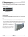
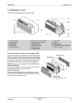
Stamped Aluminum Grille - Single Pack .......................................................68
Remote Escutcheon Kit - 10 Pack ................................................................69
Replacement Filter - 10 Pack........................................................................70
Vent Filter .....................................................................................................70
PTAC
5
Test condition of International Standards
6RWU0-03A
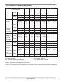
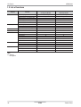
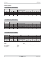
Test condition of International Standards
KSC
9306
ISO
5151
ARI
210/240
AHAM
AS
1861.1
SSA
385
DB°C(°F)
27.0
27.0
26.7(80)
26.7(80)
27.0
29.0
WB°C(°F)
19.5
19.0
19.4(67)
19.4(67)
19.0
19.0
DB°C(°F)
35.0
35.0
35.0(95)
35.0(95)
35.0
46.0
WB°C(°F)
24.0
24.0
23.9(75)
23.9(75)
24.0
24.0
DB°C(°F)
20.0
20.0
21.1(70)
21.1(70)
21.0
21.0
WB°C(°F)
15.0
15.0
15.6(60)
15.6(60)
15.0
15.5
DB°C(°F)
7.0
7.0
8.3(47)
8.3(47)
7.0
7.0
WB°C(°F)
6.0
6.0
6.1(43)
6.1(43)
6.0
6.0
DB°C(°F)
32.0
32.0
26.7(80)
32.2(90)
32.0
29.0
WB°C(°F)
23.0
23.0
19.4(67)
22.8(73)
23.0
19.0
DB°C(°F)
43.0
43.0
46.1(115)
43.3(110)
43.0
54.0
WB°C(°F)
26.0
26.0
23.9(75)
25.6(78)
26.0
24.0
DB°C(°F)
27.0
27.0
26.7(80)
26.7(80)
-
-
WB°C(°F)
19.0
19.0
19.4(67)
22.8(73)
-
-
DB°C(°F)
21.0
24.0
23.9(75)
23.9(75)
-
-
WB°C(°F)
15.0
18.0
18.3(65)
18.3(65)
-
-
DB°C(°F)
27.0
27.0
26.7(80)
26.7(80)
27.0
27.0
WB°C(°F)
24.0
24.0
23.9(75)
23.9(75)
24.0
24.0
DB°C(°F)
27.0
27.0
26.7(80)
26.7(80)
27.0
27.0
WB°C(°F)
24.0
24.0
23.9(75)
23.9(75)
24.0
24.0
DB°C(°F)
21.0
21.0
19.4(67)
21.1(70)
21.0
21.0
WB°C(°F)
15.0
15.0
13.9(57)
15.6(60)
16.0
16.0
DB°C(°F)
21.0
21.0
19.4(67)
21.1(70)
21.0
21.0
WB°C(°F)
15.0
15.0
13.9(57)
15.6(60)
16.0
16.0
CLASSIFICATION
Indoor
Cooling
Capacity
Outdoor
Indoor
Heating
Capacity
Maximum
Outdoor
Indoor
Cooling
Operating
Outdoor
Maximum
Indoor
Heating
Operating
Enclosure
Outdoor
Indoor
Sweat /
Condensate
Outdoor
Disposal
Freeze-up/
Indoor
Low
Temperature Outdoor
KS : Korea Standard
ISO : International Standard Organization
ARI : Airconditioning and Refrigeration Institute
AHAM : Association of Home Appliance Manufacturers
AS : Australia Standard
SSA : Saudi Arabian Standard
In the table above, temperatures are expressed in Fahrenheit(°F) within parentheses only for ARI and AHAM standards.
6
PTAC
General information
Introduction
6RWU0-03A
Introduction
Preface
Packaged Terminal Air-Conditioners(PTAC) of LG is the best choice a customer can avail when it comes to a quiet environment. Ultra quiet operation is the hallmark of these Air-Conditioners of LG. These range of units are suitable for Hotels and
Healthcare applications. These units have extremely low noise levels and outstanding sound prevention ratings. Moreover,
these units have higher Energy ratings which results in excellent energy savings.
These units are also provided with unique features to provide better usability and easy installation for the user.
The capacity of these PTAC models ranges from 7,000 Btu/h to 15,000 Btu/h.
Some of the important features of this units are as follows:Long term money saving: By providing features such as Gold Fin etc... to maintain the same performance throughout the life
of the Air-Conditioner.
Comfort : With features such as Wall Thermostat temperature control, Auto Restart, etc…, which gives ultimate comfort to
our customer.
These units are equipped with many standard and optional features for our customers and for details please refer to the
detailed specification followed after this description.
LG Electronics Inc.
Air Conditioning & Energy Solution Company
General information
PTAC
7
Introduction
6RWU0-03A
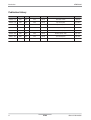
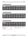
Publication History
Pub. No.
Frequency Category
Product name
Refrigerant
Notes
Published in
6RWU0 - 01A
60Hz
RAC
PTAC
R410A
New Edition of PDB
Apr.2010
6RWU0 - 01B
60Hz
RAC
PTAC
R410A
Spec sheet update
June.2010
6RWU0 – 01C
60Hz
RAC
PTAC
R410A
Spec sheet update
August. 2010
6RWU0 – 01D
60Hz
RAC
PTAC
R410A
Add Operation range
Dec. 2010
6RWU0 – 02A
60Hz
RAC
PTAC
R410A
2011 New line-up update
Apr. 2011
6RWU0 – 02B
60Hz
RAC
PTAC
R410A
Modified Capacity Table
Apr. 2012
6RWU0 – 02C
60Hz
RAC
PTAC
R410A
Spec Sheet Update
Apr. 2012
6RWU0-03A
60Hz
RAC
PTAC
R410A
2013 Model Line Up
Mar, 2013
8
PTAC
General information
6RWU0-03A
Introduction
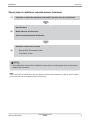
Step by step air conditioner selection process (reference)
(1)
Calculate or obtain the maximum heat load for the area to be air conditioned.
Specifications
(2)
Model features and functions
Air-flow and temperature distribution
Selection of the control system
Remote Wall Thermostat Control
(3)
Front Desk Control
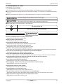
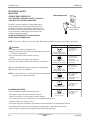
CAUTION
1. Air conditioners should not be installed in areas where corrosive gases such as acid gas or
alkaline gas is present.
Note :
Here in this PDB, the temperature units are generally expressed in Fahrenheit (°F) but for specific regions
please conform to local standards whenever necessary.
General information
PTAC
9
6RWU0-03A
10
PTAC
General information
Part 1 General information
1. Model line up .......................................................................................12
2. Nomenclature ......................................................................................13
3. Appearance ..........................................................................................14
4. List of functions ..................................................................................15
5. Features ...............................................................................................16
General information
PTAC
11
Model line up
6RWU0-03A
1. Model line up
Model names
Capacity, kW(kBtu/h)
Chassis
2.05(7)
YA
12
UYC073ALE21(LP073CD2B)
UYH073ALE21(LP073HD2B)
2.64(9)
UYC093ALE31(LP093CD3B)
UYH093ALE31(LP093HD3B)
UYC09EALE31(LP096CD3B)
UYH09EALE31(LP096HD3B)
PTAC
3.52(12)
UYC123ALE31(LP123CD3B)
UYH123ALE31(LP123HD3B)
UYC12EALE31(LP126CD3B)
UYH12EALE31(LP126HD3B)
4.4(15)
UYC153ALE31(LP153CD3B)
UYH153ALE31(LP153HD3B)
General information
6RWU0-03A
Nomenclature
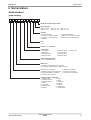
2. Nomenclature
Global standard
[New version]
U Y
C
0
7
3
A
L
E
2
1
Model Development serial number.
Heater Capacity:
0kW: No Heater 2kW: 2.0 ~ 2.9
1kW: 1.0 ~ 1.9
3kW: 3.0 ~ 3.9
Function.
A: Cooling Standard
B: Cooling + Corrosion Protection
C: Cooling + Condensate Pump
E: Electronic
4kW : 4.0 ~ 4.9
5kW : 5.0 ~ 5.9
H: Heat Pump Standard
J: Heat Pump + Corrosion Protection
K: Heat Pump + Condensate Pump
Look.
L: LG
Chassis : A – YA chassis.
Power Rating:
1: 115V, 60Hz
2: 220V, 60Hz
3: 208-230V, 60Hz
5: 200-220V, 50Hz
6: 220-240V, 50Hz
7: 110V, 50-60Hz
8: 380-415V, 50Hz
9: 380-415V, 60Hz
E: 265V, 60Hz
Cooling/Heating Capacity.
Ex) 07 -> 7,000 Btu/h Class
Model Type:
C: Cooling + Electric Heater or Cooling only.
H: Heat pump + Electric Heater or Heat Pump only.
W: Window Air Conditioner
Y: Packaged Terminal Air Conditioner
X: Through the Wall Air Conditioner
E: Casement Air Conditioner
U: SPVU Air Conditioner
L: Condole Air Conditioner
Q: Low Profile Air Conditioner
Production Center, Refrigerant
L: Changwon R22
N: India
A: Changwon R410A
Z: Brazil
C: Changwon R407C
D: Indonesia
T: China
M: Mexico
K: Turkey R22
V: Vietnam
E: Turkey R410A
S: Outsourcing
H: Thailand
U: China R410A
General information
PTAC
13
Appearance
6RWU0-03A
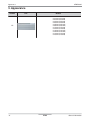
3. Appearance
Chassis
Unit
Models
UYC073ALE21(LP073CD2B)
UYH073ALE21(LP073HD2B)
UYC093ALE31(LP093CD3B)
UYH093ALE31(LP093HD3B)
UYC09EALE31(LP096CD3B)
UYH09EALE31(LP096HD3B)
UYC123ALE31(LP123CD3B)
UYH123ALE31(LP123HD3B)
UYC12EALE31(LP126CD3B)
UYH12EALE31(LP126HD3B)
UYC153ALE31(LP153CD3B)
UYH153ALE31(LP153HD3B)
YA
14
PTAC
General information
6RWU0-03A
List of functions
4. List of functions
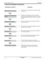
Category
Function
PTAC Type
Cooling only Models
PTAC Type
Heat Pump Models
Top discharge
Manual
2/2/2
2 way
O
O
O
O
O
O
O
O
O
O
O
Top discharge
Manual
2/2/2
2 way
O
O
O
O
O
O
O
O
O
O
O
Air discharge type
Airflow direction control (up & down)
Airflow direction control (left & right)
Air flow
Auto swing
Airflow steps (fan/cool/heat)
Airflow Direction
Deodorizing filter
Air purifying Plasma air filter
Air filter (washable / anti-fungus)
Installation Electric heater (operation)
Reliability Hot start
Auto restart operation
Micom control
Convenience Air ventilation
Forced operation
Sleep mode
Timer
Wired remote controller
Individual
Wireless remote controller
control
Wireless LCD remote control
Energy save mode
Others
Thermostat
Thermistor
O : applied
- : not applied
General information
PTAC
15
Features
6RWU0-03A
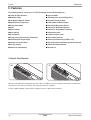
5. Features
The following features can be found in PTAC (Packaged Terminal Air-Conditioners) :n 2 -Way Air Flow Direction
n Two Fan Motors
n Washable Filters
n LED Diagnostics and Self Diagnostics
n Low Noise at High Air Volume
n 2 Position Discharge Grille
n High Efficiency Compressor
n Indoor Room Freeze Protection
n Energy Saver Mode
n Door Switch/Occupancy Sensor
n Timer
n Compressor Overload Protection
n Electric Heater
n Outdoor Air Temperature Switchover
n Deice Control
n Temperature Limits
n Air Ventilation
n Condensate Drain Valve
n Energy saving Anti-corrosion treated Fins
n Quick Heater Recovery
n Infinite Impulse Response(IIR)
n Reverse Cycle Defrosting (PTHPʼs only)
n Compressor Restart Delay
n High Temperature Heat Pump operation Protection
n Fan only Setting
n Remote Thermostat Control
n Indoor Fan Speed Setting
n Zone Sensor
2 -Way Air Flow Direction
40
15
Air Flow can be adjusted by changing the direction of the air conditionerʼs louvers to attain the desired level of comfort and
convenience. This can also increase the cooling efficiency of the air conditioner.
In order to attain maximum cooling efficiency, adjust the louvers so that they face upwards.
16
PTAC
General information
6RWU0-03A
Features
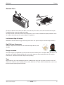
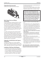
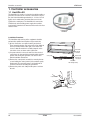
Washable Filters
The Unit uses two filters on the indoor side which can be slid easily. These filters can be taken out without removing the
Front Grille and then cleaned by washing or brushing.
The filters should be checked and cleaned every two(2) weeks or as necessary to maintain the optimal performance of the
air conditioner depending upon the region and purpose of application.
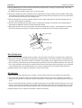
Low Noise at High Air Volume
New Blowers and Fans which are bigger and stronger than earlier ones operate at low rpmʼs and have higher efficiency.
High Efficiency Compressor
LG Rotary compressors have low noise, low vibration and higher efficiency and
reliability.
Energy save mode
This feature employs a programmable logic which enables the unit to minimize power consumption. When the switch is activated in the “on” position, the Indoor fan turns off as soon as the compressor stops running. And in the “off” mode, the
indoor fan runs continuously even if the compressor stops running.
Timer
By this feature we can set the operating time of the air conditioner from one(1) hour up to a time of 12 hours. In the “Off”
mode, the Air Conditioner stops operating after the set time, while in the “On” mode, the Air Conditioner timer can be set so
that the unit starts operating at the desired time.
General information
PTAC
17
6RWU0-03A
Features
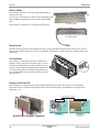
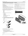
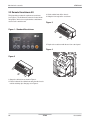
Electric Heater
Electric heaters are used in cold regions when instant heating is
required in the room.
In such cases, electric heaters are preferred over heat pump models
which sometime require long time to achieve the desired heating
effect.
Fig : Coil Heater
Electric Heater are of two types – Coil Heater and PTC Heater
Fig : PTC Heater
Deice Control
When the unit starts operating in the heating mode, then, to protect the outdoor unit pipe from freezing, “deice” control is
used. By exercising this control, the cycle is reversed into the cooling mode; to deice or defrost the condenser tubes in the
outdoor unit.
Air Ventilation
Air ventilation is carried out by means of a ventilation lever
from time to time to induct fresh air into the room. For the air
conditioner to maintain the best cooling conditions, the lever
must be in the closed position. And when the ventilation lever
is set in the open position, the damper opens and the room
air is exhausted while at the same time fresh air from outside
enters the room.
VENT
CLOSE
VENT
OPEN
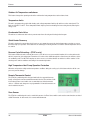
Energy saving Gold Fin
Heat exchangers are coated with anti-corrosive and Hydrophilic layers. It prevents the corrosion of heat exchanger.
Fins remain new for a long time and the efficiency of the heat exchanger remains constant thereby saving power and
maintenance cost.
Salt Spray Test Result : After 360 hours
[ Test Standard: ASTM B-117, KS D 9502 ]
Uncoated
Aluminum
Anti Corrosion Gold Fin
Hydrophilic
layer
Anticorrosion
layer
Pitting Corrosion
Aluminum
[ Aluminum]
10 mm
10 mm
Anti Corrosion Gold Fin
• Pitting corrosion
on the surface
No corrosion
Gold Fin Anti-Corrosive Treatment:
18
PTAC
General information
6RWU0-03A
Features
Infinite Impulse response (IIR)
The IIR function senses the temperature several times per second and make micro adjustments accordingly.
Compressor Restart Delay
This feature extends the overall life of the compressor by preventing the short cycling of the air-conditioner. When the compressor restarts, LG PTAC is designed to give it a minimum of three minutes to have a time of equalizing the refrigerant
pressures for optimizing the cycle.
Fan only setting
When the Fan only setting is made, only the fan on the indoor side operates while the compressor stops operating and the
unit ceases to run in the Cooling or the Heating mode.
Indoor Fan speed setting
The Indoor fan can run at HIGH or LOW speed for either COOLING or HEATING operation.
Two Fan motors
The air conditioning unit has two fan motors for providing a quiet operation and maximum efficiency.
LED Diagnostics and Self Diagnostics
LED Diagnostics feature indicates the problem by its easy to read diagnostics, when the unit does not operate properly. For
example, one blink every 2 seconds indicate compressor failure.
While Self Diagnostics feature is used in micom models and it indicates the problem by a displaying a set of error codes.
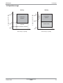
2 position discharge grille
The discharge grille can provide air flow upwards at an angle of 40˚ off vertical or 15˚ off vertical. The angle is changed by
removing the front grille and 4 screws that fasten the discharge grille to the front grille and rotating the louvers to an alternate position.
Indoor room freeze protection
When the unit senses the room temperature to be less than 40˚ F, the unit activates the fan motor and either the electric
resistance heater or the hydronic heater, to prevent the pipes or fixtures from freezing. This also overrides the front desk
control of the unit mounted controls or the wall mounted controls.
Door Switch/Occupancy Sensor
The unit is capable of accommodating a field installed door switch and occupancy sensor to operate the energy management feature by checking whether any people are present inside the room or not. If there are no people inside the room, the
energy management feature is in play.
Compressor Overload protection
This feature prevents damage of the compressor by sensing the indoor coil temperature during the heating mode. If the
indoor coil temperature is over 130˚ F, the outdoor fan is switched off and it operates again only when the temperature
drops below 120 ˚ F.
General information
PTAC
19
Features
6RWU0-03A
Outdoor Air Temperature switchover
This feature changes the operating mode of the unit from the heat pump mode to total resistance heat.
Temperature limits
The unit is programmed to provide both heating and cooling temperature limits by dip switches on the control panel. The
limits are from 50˚ F to 90˚ F. These temperature limits help to prevent overheating and overcooling thereby reducing the
energy costs.
Condensate Drain Valve
The unit has a condensate drain valve to prevent water from collecting and freezing in the basepan.
Quick Heater Recovery
The unit is designed to operate the electric heater so as to warm the room to the desired temperature set point as soon as
the Heat Pump cycle operates. This feature has an advantage of reducing the time to reach the desired temperature for better comfort.
Reverse Cycle Defrosting – (PTHPʼs only)
This feature enables the unit to activate the reverse cycle defrost so as to prevent the formation of ice on the outdoor unit,
which is exposed to cold environment. Formation of ice reduces the airflow through the coil and hence the efficiency of the
air conditioning unit. The LG PTHP employs an active reverse cycle defrost function to melt the ice off the outdoor coil for
ensuring room comfort conditions and savings from extended operation.
High Temperature Heat Pump Operation Protection
When the unit operates at high outdoor temperature conditions during the cooling cycle, this feature switches off the compressor to prevent damage.
Remote Thermostat Control
The PTAC air conditioning unit is designed and built to be operated from any
four(4) or five(5) wire remote mounted thermostat if desired. The unit has a builtin low voltage power source which can accommodate any of the thermostat
choices – manual, auto changeover or programmable. A remote thermostat can
also be added to any unit.
Zone Sensor
The PTAC air conditioning unit can be controlled by means of a Zone Sensor which carries out the same functions as that of
a Wall Thermostat. In other words, it is a remote wall thermostat.
20
PTAC
General information
6RWU0-03A
Part 2 Product data
1 YA chassis ...........................................................................................22
1.1 Features ...........................................................................................................22
1.2 List of functions ................................................................................................23
1.3 Specifications ...................................................................................................24
1.4 Dimensions.......................................................................................................30
1.5 Piping diagrams................................................................................................31
1.6 Wiring diagrams................................................................................................33
1.7 Capacity tables ..................................................................................................35
1.8 Electrical characteristics ....................................................................................43
1.9 Operation range.................................................................................................44
2 Control Devices..................................................................................45
2.1 Electronic Controls ...........................................................................................45
21
PTAC
Product Data
6RWU0-03A
YA Chassis
1. YA Chassis
Models : UYC073ALE21(LP073CD2B) UYC093ALE31(LP093CD3B) UYC123ALE31(LP123CD3B) UYC153ALE31(LP153CD3B)
UYH073ALE21(LP073HD2B) UYH093ALE31(LP093HD3B) UYH123ALE31(LP123HD3B) UYH153ALE31(LP153HD3B)
UYC09EALE31(LP096CD3B) UYC12EALE31(LP126CD3B)
UYH09EALE31(LP096HD3B) UYH12EALE31(LP126HD3B)
1.1 Features
n 2 -Way Air Flow Direction
n Washable Filters
n Low Noise at High Air Volume
n High Efficiency Compressor
n Energy Saver Mode
n Timer
n Electric Heater
n Deice Control
n Air Ventilation
n Energy saving Anti-corrosion treated Fins
n Infinite Impulse Response(IIR)
n Compressor Restart Delay
n Fan only Setting
n Indoor Fan Speed Setting
Product Data
n Two Fan Motors
n LED Diagnostics and Self Diagnostics
n 2 Position Discharge Grille
n Indoor Room Freeze Protection
n Door Switch/Occupancy Sensor
n Compressor Overload Protection
n Outdoor Air Temperature Switchover
n Temperature Limits
n Condensate Drain Valve
n Quick Heater Recovery
n Reverse Cycle Defrosting (PTHPʼs only)
n High Temperature Heat Pump operation Protection
n Remote Thermostat Control
n Zone Sensor
PTAC
22
YA Chassis
6RWU0-03A
1.2 List of functions
Category
Air flow
Air purifying
Installation
Reliability
Convenience
Individual control
Others
Function
Air discharge type
Airflow direction control (up & down)
Airflow direction control (left & right)
Auto swing
Airflow steps (fan/cool/heat)
Airflow Direction
Deodorizing filter
Plasma air filter
Air filter (washable / anti-fungus)
Electric heater (operation)
Hot start
Auto restart operation
Micom control
Air ventilation
Forced operation
Sleep mode
Timer
Wired remote controller
Wireless remote controller
Wireless LCD remote control
Energy saver switch
Thermostat
Thermistor
PTAC
Cooling only Models
Top discharge
Manual
2/2/2
2 way
O
O
O
O
O
O
O
O
O
O
O
PTAC
Heat Pump Models
Top discharge
Manual
2/2/2
2 way
O
O
O
O
O
O
O
O
O
O
O
Note :
O : applied
- : not applied
23
PTAC
Product Data
6RWU0-03A
YA Chassis
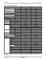
1.3 Specifications
208-230V COOLING ONLY MODELS
Buyer Models
LG Models
Cooling Capacity
Heating Capacity ( for Heat Pump
models)
Electric Heater capacity
Power Input
Cooling/Heating
Running Current Cooling/Heating
Electric Heater Current
EER
COP
Power Supply
Power Factor
MCA
MOP
Air Flow Rate
Dehumidification
Indoor,(H/L)
Outdoor,Max
LP073CD2B
UYC073ALE21
kW
Btu/h.
kW
Btu/h.
kW
Btu/h.
W
A
A
W/W
Btu/h.W
W/W
Ø / V / Hz
%
A
A
m3/min(CFM)
m3/min(CFM)
pts/h
dB(A)±3
dB(A)±3
g(oz)
Indoor,H/M/L
Outdoor,Max
Refrigerant & Charge
Type
Model
Motor Type
Compressor
Oil Type
Oil Charge
cc
RLA/LRA
A
O.L.P Name
Type(In/Out)
Motor Type(In/Out)
Fan
FLA(In/Out)
A
Motor Output(In/Out)
W
Evaporator
Rows * Column * FPI
Heat Exchanger
Condensor
Rows * Column * FPI
Power Supply Cable (Power Cord)
No. * AWG
mm
Dimensions ( W * H * D)
inch
Net Weight
kg(lbs)
Tool Code(Chassis)
Operating Range Voltage (Min/Max)
Temperature Control
Energy Saver Mode
Prefilter(washable/anti-fungus)
Plasma Filter
Steps, Fan/Cool/Heat
Airflow Direction Control(up&down)
Airflow Direction Control(left&right)
Remote Controller Type
Cooling
Setting Temperature
Range
Features
Heating
Auto Operation (Micom Control)
Panel Touch Type
Timer
Air Discharge
Air-Ventilation
Deice Control(Defrost)
Hot Start
Look
Cabinet Type(Chassis Type)
Special Function
Sound Level
2.08
7,100
2.4
8,200
535
2.7
11.5
3.90
13.3
1 / 208 / 60
95
2.14
7,300
2.5
8,600
550
2.5
10.9
3.90
13.3
1 / 230 / 60
96
14.9
15.0
7.6(270)/6.3(225)
17(600)
1.7
45/-/43
61
R410A, 740(26.1)
Rotary(Non Tropical)
GA060KAA
PSC
POE(RB68A)orPVE(FVC68D)
310
2.9/16
B120-160-241E
Cross Flow Fan
Axial Fan
BLDC/BLDC
0.36/0.36
20/65
2R *12C *18FPI
3R *17C *20FPI
3 * 12
1,066 * 406 * 537
42 * 16 * 21
43(95)
YA
187/253
Thermistor
O
O
2/2/2
Manual
Wall Thermostat
54℉ ~ 86℉(12.2℃ ~ 30℃)
54℉ ~ 86℉(12.2℃ ~ 30℃)
O
Micom
12h, On/Off
Top
O
L - Look
Slide In-Out
Electric Heater
LP093CD3B
UYC093ALE31
2.73
9,300
3.1
10,500
730
3.7
14.9
3.72
12.7
1 / 208 / 60
95
2.78
9,500
3.5
11,900
745
3.4
15.2
3.72
12.7
1 / 230 / 60
95
19.5
20.0
7.6(270)/6.3(225)
17(600)
2.6
46/-/44
61
R410A,600(21.2)
Rotary(Non Tropical)
GA080KBA
PSC
POE(RB68A)orPVE(FVC68D)
230
3.7/19
B145-155-241E
Cross Flow Fan
Axial Fan
BLDC/BLDC
0.36/0.36
26/66
2R *10C *19FPI
3R *17C *20FPI
3 * 12
1,066 * 406 * 537
42 * 16 * 21
43(95)
YA
187/253
Thermistor
O
O
2/2/2
Manual
Wall Thermostat
54℉ ~ 86℉(12.2℃ ~ 30℃)
54℉ ~ 86℉(12.2℃ ~ 30℃)
O
Micom
12h, On/Off
Top
O
L - Look
Slide In-Out
Electric Heater
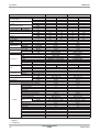
Note : ○ : applied
- : not applied
Product Data
PTAC
24
YA Chassis
6RWU0-03A
Buyer Models
LG Models
Cooling Capacity
Heating Capacity ( for Heat Pump
models)
Electric Heater capacity
Power Input
Cooling/Heating
Running Current Cooling/Heating
Electric Heater Current
EER
COP
Power Supply
Power Factor
MCA
MOP
Air Flow Rate
Dehumidification
Indoor,(H/L)
Outdoor,Max
LP123CD3B
UYC123ALE31
kW
Btu/h.
kW
Btu/h.
kW
Btu/h.
W
A
A
W/W
Btu/h.W
W/W
Ø / V / Hz
%
A
A
m3/min(CFM)
m3/min(CFM)
pts/h
dB(A)±3
dB(A)±3
g(oz)
Indoor,H/M/L
Outdoor,Max
Refrigerant & Charge
Type
Model
Motor Type
Compressor
Oil Type
Oil Charge
cc
RLA/LRA
A
O.L.P Name
Type(In/Out)
Motor Type(In/Out)
Fan
FLA(In/Out)
A
Motor Output(In/Out)
W
Evaporator
Rows * Column * FPI
Heat Exchanger
Condensor
Rows * Column * FPI
Power Supply Cable (Power Cord)
No. * AWG
mm
Dimensions ( W * H * D)
inch
Net Weight
kg(lbs)
Tool Code(Chassis)
Operating Range Voltage (Min/Max)
Temperature Control
Energy Saver Mode
Prefilter(washable/anti-fungus)
Plasma Filter
Steps, Fan/Cool/Heat
Airflow Direction Control(up&down)
Airflow Direction Control(left&right)
Remote Controller Type
Cooling
Setting Temperature
Range
Features
Heating
Auto Operation (Micom Control)
Panel Touch Type
Timer
Air Discharge
Air-Ventilation
Deice Control(Defrost)
Hot Start
Look
Cabinet Type(Chassis Type)
Special Function
Sound Level
3.52
12,000
3.1
10,500
1,005
5.1
14.9
3.49
11.9
1 / 208 / 60
95
3.58
12,200
3.5
11,900
1,025
4.7
15.2
3.49
11.9
1 / 230 / 60
95
19.5
20.0
11.9(420)/10.0(353)
20(706)
3.0
50/-/48
63
R410A, 610(21.5)
Rotary(Non Tropical)
PA108M1C
PSC
ESTER OIL VG74
350
5.0/27
BF910-MA
Cross Flow Fan
Axial Fan
BLDC/BLDC
0.36/0.36
41/74
2R *10C *19FPI
3R *17C *20FPI
3 * 12
1,066 * 406 * 537
42 * 16 * 21
45(99)
YA
187/253
Thermistor
O
O
2/2/2
Manual
Wall Thermostat
54℉ ~ 86℉(12.2℃ ~ 30℃)
54℉ ~ 86℉(12.2℃ ~ 30℃)
O
Micom
12h, On/Off
Top
O
L - Look
Slide In-Out
Electric Heater
LP153CD3B
UYC153ALE31
4.37
14,900
3.1
10,500
1,330
6.6
14.9
3.28
11.2
1 / 208 / 60
97
4.43
15,100
3.5
11,900
1,345
6.1
15.2
3.28
11.2
1 / 230 / 60
96
19.5
20.0
11.9(420)/10.0(353)
20(706)
4.3
51/-/49
64
R410A, 910(32.1)
Rotary(Non Tropical)
PA140M2C
PSC
ESTER OIL VG74
440
6.55/38.6
INTERNAL
Cross Flow Fan
Axial Fan
BLDC/BLDC
0.36/0.36
41/74
2R *10C *19FPI
3R *17C *20FPI
3 * 12
1,066 * 406 * 537
42 * 16 * 21
52(115)
YA
187/253
Thermistor
O
O
2/2/2
Manual
Wall Thermostat
54℉ ~ 86℉(12.2℃ ~ 30℃)
54℉ ~ 86℉(12.2℃ ~ 30℃)
O
Micom
12h, On/Off
Top
O
L - Look
Slide In-Out
Electric Heater
Note : ○ : applied
- : not applied
25
PTAC
Product Data
6RWU0-03A
YA Chassis
208-230V HEAT PUMP MODELS
Buyer Models
LG Models
Cooling Capacity
Heating Capacity ( for Heat Pump
models)
Electric Heater capacity
Power Input
Cooling/Heating
Running Current Cooling/Heating
Electric Heater Current
EER
COP
Power Supply
Power Factor
MCA
MOP
Air Flow Rate
Dehumidification
Indoor,(H/L)
Outdoor,Max
LP073HD2B
UYH073ALE21
kW
Btu/h.
kW
Btu/h.
kW
Btu/h.
W
A
A
W/W
Btu/h.W
W/W
Ø / V / Hz
%
A
A
m3/min(CFM)
m3/min(CFM)
pts/h
dB(A)±3
dB(A)±3
g(oz)
Indoor,H/M/L
Outdoor,Max
Refrigerant & Charge
Type
Model
Motor Type
Compressor
Oil Type
Oil Charge
cc
RLA/LRA
A
O.L.P Name
Type(In/Out)
Motor Type(In/Out)
Fan
FLA(In/Out)
A
Motor Output(In/Out)
W
Evaporator
Rows * Column * FPI
Heat Exchanger
Condensor
Rows * Column * FPI
Power Supply Cable (Power Cord)
No. * AWG
mm
Dimensions ( W * H * D)
inch
Net Weight
kg(lbs)
Tool Code(Chassis)
Operating Range Voltage (Min/Max)
Temperature Control
Energy Saver Mode
Prefilter(washable/anti-fungus)
Plasma Filter
Steps, Fan/Cool/Heat
Airflow Direction Control(up&down)
Airflow Direction Control(left&right)
Remote Controller Type
Cooling
Setting Temperature
Range
Features
Heating
Auto Operation (Micom Control)
Panel Touch Type
Timer
Air Discharge
Air-Ventilation
Deice Control(Defrost)
Hot Start
Look
Cabinet Type(Chassis Type)
Special Function
Sound Level
2.08
7,100
1.82
6,200
2.4
8,200
535/500
2.7/2.6
11.5
3.90
13.3
3.6
1 / 208 / 60
95
2.14
7,300
1.88
6,400
2.5
8,600
550/520
2.5/2.4
10.9
3.90
13.3
3.6
1 / 230 / 60
96
14.9
15.0
7.6(270)/6.3(225)
17(600)
1.7
45/-/43
61
R410A, 740(26.1)
Rotary(Non Tropical)
GA060KAA
PSC
POE(RB68A)orPVE(FVC68D)
310
2.9/16
B120-160-241E
Cross Flow Fan
Axial Fan
BLDC/BLDC
0.36/0.36
20/65
2R *12C *18FPI
3R *17C *20FPI
3 * 12
1,066 * 406 * 537
42 * 16 * 21
43(95)
YA
187/253
Thermistor
O
O
2/2/2
Manual
Wall Thermostat
54℉ ~ 86℉(12.2℃ ~ 30℃)
54℉ ~ 86℉(12.2℃ ~ 30℃)
O
Micom
12h, On/Off
Top
O
O
L - Look
Slide In-Out
Electric Heater
LP093HD3B
UYH093ALE31
2.73
9,300
2.34
8,000
3.1
10,500
720/655
3.6/3.3
14.9
3.78
12.9
3.6
1 / 208 / 60
96
2.78
9,500
2.40
8,200
3.5
11,900
735/670
3.3/3.0
15.2
3.78
12.9
3.6
1 / 230 / 60
97
19.5
20.0
7.6(270)/6.3(225)
17(600)
2.6
46/-/44
61
R410A, 910(32.1)
Rotary(Non Tropical)
GKU086KAB
PSC
POE(RB68A)orPVE(FVC68D)
330
4.0/19
LMSH2Z69-L002
Cross Flow Fan
Axial Fan
BLDC/BLDC
0.36/0.36
26/66
2R *10C *19FPI
3R *17C *20FPI
3 * 12
1,066 * 406 * 537
42 * 16 * 21
48(106)
YA
187/253
Thermistor
O
O
2/2/2
Manual
Wall Thermostat
54℉ ~ 86℉(12.2℃ ~ 30℃)
54℉ ~ 86℉(12.2℃ ~ 30℃)
O
Micom
12h, On/Off
Top
O
O
L - Look
Slide In-Out
Electric Heater
Note : ○ : applied
- : not applied
Product Data
PTAC
26
YA Chassis
6RWU0-03A
Buyer Models
LG Models
Cooling Capacity
Heating Capacity ( for Heat Pump
models)
Electric Heater capacity
Power Input
Cooling/Heating
Running Current Cooling/Heating
Electric Heater Current
EER
COP
Power Supply
Power Factor
MCA
MOP
Air Flow Rate
Dehumidification
Indoor,(H/L)
Outdoor,Max
LP123HD3B
UYH123ALE31
kW
Btu/h.
kW
Btu/h.
kW
Btu/h.
W
A
A
W/W
Btu/h.W
W/W
Ø / V / Hz
%
A
A
m3/min(CFM)
m3/min(CFM)
pts/h
dB(A)±3
dB(A)±3
g(oz)
Indoor,H/M/L
Outdoor,Max
Refrigerant & Charge
Type
Model
Motor Type
Compressor
Oil Type
Oil Charge
cc
RLA/LRA
A
O.L.P Name
Type(In/Out)
Motor Type(In/Out)
Fan
FLA(In/Out)
A
Motor Output(In/Out)
W
Evaporator
Rows * Column * FPI
Heat Exchanger
Condensor
Rows * Column * FPI
Power Supply Cable (Power Cord)
No. * AWG
mm
Dimensions ( W * H * D)
inch
Net Weight
kg(lbs)
Tool Code(Chassis)
Operating Range Voltage (Min/Max)
Temperature Control
Energy Saver Mode
Prefilter(washable/anti-fungus)
Plasma Filter
Steps, Fan/Cool/Heat
Airflow Direction Control(up&down)
Airflow Direction Control(left&right)
Remote Controller Type
Cooling
Setting Temperature
Range
Features
Heating
Auto Operation (Micom Control)
Panel Touch Type
Timer
Air Discharge
Air-Ventilation
Deice Control(Defrost)
Hot Start
Look
Cabinet Type(Chassis Type)
Special Function
Sound Level
3.52
12,000
3.11
10,600
3.1
10,500
1,010/885
5.2/4.6
14.9
3.49
11.9
3.5
1 / 208 / 60
93
3.58
12,200
3.17
10,800
3.5
11,900
1,025/905
4.8/4.3
15.2
3.49
11.9
3.5
1 / 230 / 60
93
19.5
20.0
11.9(420)/10.0(353)
20(706)
3.0
50/-/48
63
R410A, 850(30.0)
Rotary(Non Tropical)
GKU113KAB
PSC
POE(RB68A) or PVE(FVC68D)
330
5.0/26
MRA98996-12026
Cross Flow Fan
Axial Fan
BLDC/BLDC
0.36/0.36
41/74
2R *10C *19FPI
3R * 17C * 20FPI
3 * 12
1,066 * 406 * 537
42 * 16 * 21
48(106)
YA
187/253
Thermistor
O
O
2/2/2
Manual
Wall Thermostat
54℉ ~ 86℉(12.2℃ ~ 30℃)
54℉ ~ 86℉(12.2℃ ~ 30℃)
O
Micom
12h, On/Off
Top
O
O
L - Look
Slide In-Out
Electric Heater
LP153HD3B
UYH153ALE31
4.37
14,900
3.87
13,200
3.1
10,500
1,330/1250
6.6/6.2
14.9
3.28
11.2
3.1
1 / 208 / 60
97
4.43
15,100
3.93
13,400
3.5
11,900
1,345/1265
6.1/5.7
15.2
3.28
11.2
3.1
1 / 230 / 60
96
19.5
20.0
11.9(420)/10.0(353)
20(706)
4.3
51/-/49
64
R410A, 910(32.1)
Rotary(Non Tropical)
PA140M2C
PSC
ESTER OIL VG74
440
6.55/38.6
INTERNAL
Cross Flow Fan
Axial Fan
BLDC/BLDC
0.36/0.36
41/74
2R *10C *19FPI
3R *17C *20FPI
3 * 12
1,066 * 406 * 537
42 * 16 * 21
52(115)
YA
187/253
Thermistor
O
O
2/2/2
Manual
Wall Thermostat
54℉ ~ 86℉(12.2℃ ~ 30℃)
54℉ ~ 86℉(12.2℃ ~ 30℃)
O
Micom
12h, On/Off
Top
O
O
L - Look
Slide In-Out
Electric Heater
Note : ○ : applied
- : not applied
27
PTAC
Product Data
6RWU0-03A
YA Chassis
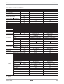
265V COOLING ONLY MODELS
Buyer Models
LG Models
Cooling Capacity
Heating Capacity ( for Heat Pump
models)
Electric Heater capacity
Power Input
Cooling/Heating
Running Current Cooling/Heating
Electric Heater Current
EER
COP
Power Supply
Power Factor
MCA
MOP
Air Flow Rate
Dehumidification
Indoor,(H/L)
Outdoor,Max
kW
Btu/h.
kW
Btu/h.
kW
Btu/h.
W
A
A
W/W
Btu/h.W
W/W
Ø / V / Hz
%
A
A
m3/min(CFM)
m3/min(CFM)
pts/h
dB(A)±3
dB(A)±3
g(oz)
Indoor,H/M/L
Outdoor,Max
Refrigerant & Charge
Type
Model
Motor Type
Compressor
Oil Type
Oil Charge
cc
RLA/LRA
A
O.L.P Name
Type(In/Out)
Motor Type(In/Out)
Fan
FLA(In/Out)
A
Motor Output(In/Out)
W
Evaporator
Rows * Column * FPI
Heat Exchanger
Condensor
Rows * Column * FPI
Power Supply Cable (Power Cord)
No. * AWG
mm
Dimensions ( W * H * D)
inch
Net Weight
kg(lbs)
Tool Code(Chassis)
Operating Range Voltage (Min/Max)
Temperature Control
Energy Saver Mode
Prefilter(washable/anti-fungus)
Plasma Filter
Steps, Fan/Cool/Heat
Airflow Direction Control(up&down)
Airflow Direction Control(left&right)
Remote Controller Type
Cooling
Setting Temperature
Range
Features
Heating
Auto Operation (Micom Control)
Panel Touch Type
Timer
Air Discharge
Air-Ventilation
Deice Control(Defrost)
Hot Start
Look
Cabinet Type(Chassis Type)
Special Function
Sound Level
LP096CD3B
UYC09EALE31
2.84
9,700
3.7
12,600
755
3.0
14.0
3.75
12.8
1 / 265 / 60
95
17.9
20
7.6(270)/6.3(225)
17(600)
2.6
46/-/44
61
R410A, 895(31.6)
Rotary(Non Tropical)
GKU086QAA
PSC
POE(RB68A) or PVE(FVC68D)
330
3.3/20
LPMD2W69-L002
Cross Flow Fan
Axial Fan
BLDC/BLDC
0.36/0.36
26/66
2R *10C *19FPI
3R *17C *20FPI
3 * 12
1,066 * 406 * 537
42 * 16 * 21
48(106)
YA
239/292
Thermistor
O
O
2/2/2
Manual
Wall Thermostat
54℉ ~ 86℉(12.2℃ ~ 30℃)
54℉ ~ 86℉(12.2℃ ~ 30℃)
O
Micom
12h, On/Off
Top
O
L - Look
Slide In-Out
Coil Heater
LP126CD3B
UYC12EALE31
3.58
12,200
3.7
12,600
1,025
4.0
14.0
3.49
11.9
1 / 265 / 60
97
17.9
20
11.9(420)/10.0(353)
20(706)
3.0
50/-/48
63
R410A, 910(32.1)
Rotary(Non Tropical)
GKU113QAA
PSC
POE(RB68A) or PVE(FVC68D)
330
4.4/22
LMSH2Z69-L002
Cross Flow Fan
Axial Fan
BLDC/BLDC
0.36/0.36
41/74
2R *10C *19FPI
3R *17C *20FPI
3 * 12
1,066 * 406 * 537
42 * 16 * 21
48(106)
YA
239/292
Thermistor
O
O
2/2/2
Manual
Wall Thermostat
54℉ ~ 86℉(12.2℃ ~ 30℃)
54℉ ~ 86℉(12.2℃ ~ 30℃)
O
Micom
12h, On/Off
Top
O
L - Look
Slide In-Out
Coil Heater
Note : ○ : applied
- : not applied
Product Data
PTAC
28
YA Chassis
6RWU0-03A
265V HEAT PUMP MODELS
Buyer Models
LG Models
Cooling Capacity
Heating Capacity ( for Heat Pump
models)
Electric Heater capacity
Power Input
Cooling/Heating
Running Current Cooling/Heating
Electric Heater Current
EER
COP
Power Supply
Power Factor
MCA
MOP
Air Flow Rate
Dehumidification
Indoor,(H/L)
Outdoor,Max
kW
Btu/h.
kW
Btu/h.
kW
Btu/h.
W
A
A
W/W
Btu/h.W
W/W
Ø / V / Hz
%
A
A
m3/min(CFM)
m3/min(CFM)
pts/h
dB(A)±3
dB(A)±3
g(oz)
Indoor,H/M/L
Outdoor,Max
Refrigerant & Charge
Type
Model
Motor Type
Compressor
Oil Type
Oil Charge
cc
RLA/LRA
A
O.L.P Name
Type(In/Out)
Motor Type(In/Out)
Fan
FLA(In/Out)
A
Motor Output(In/Out)
W
Evaporator
Rows * Column * FPI
Heat Exchanger
Condensor
Rows * Column * FPI
Power Supply Cable (Power Cord)
No. * AWG
mm
Dimensions ( W * H * D)
inch
Net Weight
kg(lbs)
Tool Code(Chassis)
Operating Range Voltage (Min/Max)
Temperature Control
Energy Saver Mode
Prefilter(washable/anti-fungus)
Plasma Filter
Steps, Fan/Cool/Heat
Airflow Direction Control(up&down)
Airflow Direction Control(left&right)
Remote Controller Type
Cooling
Setting Temperature
Range
Features
Heating
Auto Operation (Micom Control)
Panel Touch Type
Timer
Air Discharge
Air-Ventilation
Deice Control(Defrost)
Hot Start
Look
Cabinet Type(Chassis Type)
Special Function
Sound Level
LP096HD3B
UYH09EALE31
2.84
9,700
2.49
8,500
3.7
12,600
755/690
3.0/2.7
14.0
3.75
12.8
3.6
1 / 265 / 60
95
17.9
20
7.6(270)/6.3(225)
17(600)
2.6
46/-/44
61
R410A, 895(31.6)
Rotary(Non Tropical)
GKU086QAA
PSC
POE(RB68A) or PVE(FVC68D)
330
3.3/20
LPMD2W69-L002
Cross Flow Fan
Axial Fan
BLDC/BLDC
0.36/0.36
26/66
2R *10C *19FPI
3R *17C *20FPI
3 * 12
1,066 * 406 * 537
42 * 16 * 21
48(106)
YA
239/292
Thermistor
O
O
2/2/2
Manual
Wall Thermostat
54℉ ~ 86℉(12.2℃ ~ 30℃)
54℉ ~ 86℉(12.2℃ ~ 30℃)
O
Micom
12h, On/Off
Top
O
O
L - Look
Slide In-Out
Coil Heater
LP126HD3B
UYH12EALE31
3.58
12,200
3.22
11,000
3.7
12,600
1,025/895
4.0/3.5
14.0
3.49
11.9
3.6
1 / 265 / 60
97
17.9
20
11.9(420)/10.0(353)
20(706)
3.0
50/-/48
63
R410A, 910(32.1)
Rotary(Non Tropical)
GKU113QAA
PSC
POE(RB68A) or PVE(FVC68D)
330
4.4/22
LMSH2Z69-L002
Cross Flow Fan
Axial Fan
BLDC/BLDC
0.36/0.36
41/74
2R *10C *19FPI
3R *17C *20FPI
3 * 12
1,066 * 406 * 537
42 * 16 * 21
48(106)
YA
239/292
Thermistor
O
O
2/2/2
Manual
Wall Thermostat
54℉ ~ 86℉(12.2℃ ~ 30℃)
54℉ ~ 86℉(12.2℃ ~ 30℃)
O
Micom
12h, On/Off
Top
O
O
L - Look
Slide In-Out
Coil Heater
Note : ○ : applied
- : not applied
29
PTAC
Product Data
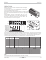
Product Data
1
2
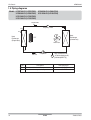
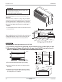
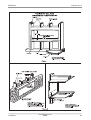
1,066mm (42")
TOP VIEW
PTAC
Architectural Grille
3
5
Remark
CHASSIS CODE : YA
an air guide should be installed on the outdoor side.
2. In an area or space having no proper circulation,
1. The unit should not be installed in a closed area.
■ Note
76, Seongsang-dong, Changwon City, Gyeongnam,
641-713, Korea
TEL : 82 – 55 – 269 - 3506
www.lge.com/airconditioner
3
537mm(21")
Vertical Air Deflector
2
4
Inlet Grille
Part name
1
Item No.
406mm (16")
PTAC
6RWU0-03A
YA Chassis
1.4 Dimensions
30
406mm (16")
YA Chassis
6RWU0-03A
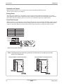
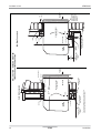
1.5 Piping diagrams
Models : UYC073ALE21(LP073CD2B)
UYC093ALE31(LP093CD3B)
UYC123ALE31(LP123CD3B)
UYC153ALE31(LP153CD3B)
UYC09EALE31(LP096CD3B)
UYC12EALE31(LP126CD3B)
Liquid side
Capillary Tube
Th2
Th1
Heat
Exchanger
(Evaporator)
Heat
Exchanger
(Condenser)
C.F.F
Axial Fan
Gas side
LOC.
31
Compressor
Description
High Pressure S/W
2
H/P : 41.8/32.6(kgf/cm G)
2
[595/463(lbf/in G)]
PCB Connector
Th1
Thermistor for indoor Air temperature
CN-IDAT2
Th2
Thermistor for evaporator temperature
CN-IDPT
PTAC
Product Data
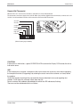
6RWU0-03A
YA Chassis
Models : UYH073ALE21(LP073HD2B)
UYH093ALE31(LP093HD3B)
UYH123ALE31(LP123HD3B)
UYH153ALE31(LP153HD3B)
UYH09EALE31(LP096HD3B)
UYH12EALE31(LP126HD3B)
CAPILLARY TUBE
(HEAT)
CAPILLARY TUBE
(COOL)
CHECK VALVE
Th2
Th3
Th1
Th4
Capi
HEAT
EXCHANGER
(EVAPORATOR)
Th2
Th1
Heat
Exchanger
(Evaporator)
HEAT
EXCHANGER
(CONDENSER)
Heat
Exchanger
(Condense
C.F.F.
Axial Fan
REVERSING VALVE Th4
ACCUMULATOR
H/P
Compressor
Reversing Valve
Accumulator
LOC.
Product Data
High Pressure
Th3 S/W
: 41.8/32.6(kgf/cm2G)
[595/463 (lbf/in2G)
Description
PCB Connector
Th1
Thermistor for indoor air temperature
CN-IDAT2
Th2
Thermistor for evaporator temperature
CN-IDPT
Th3
Thermistor for outdoor air temperature
Th4
Thermistor for condenser temperature
PTAC
Cooling
Heating
CN-ODT
32
YA Chassis
6RWU0-03A
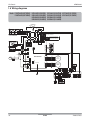
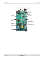
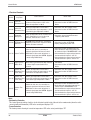
1.6 Wiring diagrams
Models : UYC073ALE21(LP073CD2B) UYC093ALE31(LP093CD3B) UYC123ALE31(LP123CD3B) UYC153ALE31(LP153CD3B)
UYH073ALE21(LP073HD2B) UYH093ALE31(LP093HD3B) UYH123ALE31(LP123HD3B) UYH153ALE31(LP153HD3B)
UYC09EALE31(LP096CD3B) UYC12EALE31(LP126CD3B)
UYH09EALE31(LP096HD3B) UYH12EALE31(LP126HD3B)
POWER INPUT
NEUTRAL
WH
LIVE
BK
GN/YL
BK1
BK2
BL
BK3
RD
BK4
BL
OR
TB2
RD
TB1
OR
WH
BK
INDOOR AIR THERMISTOR
INDOOR COIL THERMISTOR
OUTDOOR AIR THERMISTOR
OUTDOOR COIL THERMISTOR
CN-THERMO-S CN-AUX-S
CN-IDPT CN-ODT
BK
BK
HERM
OLP
WCN-NOISE
CN-MOTOR_ODF
CN-EXT(L)
CN-EXT(N) CN_N
WH
250V/T3.15A
FUSE
RY-COMP
C
MAIN PWB.ASM
CN-MOTOR_IDF
CN-ICR
BL
RD
BR
R
CN-DIP
CN-4WAY
F
COMP S
CN-DISP2
BK
CN-DISP1
BK
CN_WRITE
BK
BK
CN-PRESS
Pressure
Switch
CN-IDAT2
YL
BL
WH
BK
YL
BL
WH
BK
RD
RD
YL
BL
WH
BK
YL
BL
WH
BK
RD
RD
INDOOR
FAN
MOTOR
OUTDOOR
FAN
MOTOR
BK
33
PTAC
CN-CC_S
CN-WRITE_S
CN-CC
CN-WRITE
Product Data
6RWU0-03A
YA Chassis
CN-AUX-S
CN-THERMO-S
CN-IDPT
CN-ODT
CN-IDAT2
CN-DISP1
CN-DISP2
CN-PRESS
CN-WRITE
CN-4WAY
CN-DIP
CN-ICR
CN-MOTOR_IDF
CN-EXT(L)
CN-MOTOR_ODF
CN-EXT(N)
CN-N
Product Data
PTAC
34
YA Chassis
6RWU0-03A
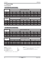
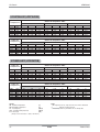
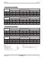
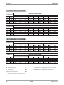
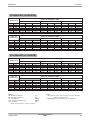
1.7 Capacity tables
Cooling Capacity
UYC073ALE21(LP073CD2B)
Indoor Air
Temperature
WB°F
57.2
60.8
64.4
66.2
71.6
75.2
DB°F
68.0
71.6
77.0
80.6
86.0
89.6
Outdoor Air Temperature : DB°F
68
TC
5.92
6.91
7.71
8.07
8.85
9.19
Indoor Air
Temperature
WB°F
57.2
60.8
64.4
66.2
71.6
75.2
DB°F
68.0
71.6
77.0
80.6
86.0
89.6
SHC
5.80
5.65
5.51
5.44
5.26
5.15
77
PI
0.36
0.37
0.37
0.38
0.38
0.39
TC
5.80
6.76
7.55
7.90
8.67
8.99
SHC
5.88
5.71
5.56
5.49
5.30
5.19
89.6
PI
0.43
0.44
0.44
0.45
0.46
0.46
TC
5.52
6.44
7.19
7.52
8.26
8.57
SHC
6.00
5.82
5.66
5.58
5.38
5.25
PI
0.50
0.51
0.52
0.52
0.53
0.54
Outdoor Air Temperature : DB°F
95
TC
5.36
6.25
6.98
7.30
8.01
8.31
SHC
6.06
5.87
5.70
5.62
5.41
5.28
104
PI
0.53
0.54
0.54
0.55
0.56
0.57
TC
5.16
6.02
6.72
7.03
7.71
8.00
SHC
6.15
5.95
5.77
5.69
5.46
5.33
109.4
PI
0.56
0.57
0.58
0.59
0.60
0.60
TC
4.99
5.82
6.50
6.80
7.46
7.74
SHC
6.21
6.00
5.82
5.73
5.49
5.36
TC
7.19
8.39
9.36
9.79
10.75
11.15
SHC
7.67
7.45
7.24
7.14
6.88
6.72
PI
0.58
0.59
0.60
0.61
0.62
0.62
UYC093ALE31(LP093CD3B)
Indoor Air
Temperature
WB°F
57.2
60.8
64.4
66.2
71.6
75.2
DB°F
68.0
71.6
77.0
80.6
86.0
89.6
Outdoor Air Temperature : DB°F
68
TC
7.71
8.99
10.03
10.50
11.52
11.96
Indoor Air
Temperature
WB°F
57.2
60.8
64.4
66.2
71.6
75.2
DB°F
68.0
71.6
77.0
80.6
86.0
89.6
SHC
7.43
7.23
7.04
6.96
6.72
6.59
77
PI
0.49
0.50
0.50
0.51
0.52
0.53
SHC
7.52
7.31
7.12
7.03
6.78
6.64
89.6
PI
0.58
0.59
0.60
0.61
0.61
0.62
PI
0.67
0.69
0.70
0.71
0.72
0.73
Outdoor Air Temperature : DB°F
95
TC
6.97
8.14
9.08
9.50
10.43
10.82
SHC
7.75
7.51
7.29
7.19
6.92
6.76
104
PI
0.71
0.72
0.73
0.75
0.75
0.77
Symbol
DB : Dry Bulb Temperature
[°F]
WB : Wet Bulb Temperature
[°F]
TC : Total Capacity
[kBtu/h]
SHC : Sensible Heating Capacity
[kBtu/h]
PI : Power Input
[kW]
(Comp.+ indoor fan motor + outdoor fan motor)
35
TC
7.54
8.80
9.82
10.28
11.28
11.70
TC
6.71
7.83
8.74
9.15
10.04
10.42
SHC
7.87
7.62
7.39
7.28
6.99
6.82
109.4
PI
0.76
0.77
0.78
0.79
0.80
0.81
TC
6.49
7.58
8.45
8.85
9.71
10.08
SHC
7.94
7.68
7.44
7.33
7.03
6.85
PI
0.78
0.79
0.80
0.82
0.83
0.84
Notes
1. All capacities are net, evaporator fan motor heat is deducted.
2.
Indicates nominal capacity.
3. Direct interpolation is permissible. Do not extrapolate
PTAC
Product Data
6RWU0-03A
YA Chassis
UYC123ALE31(LP123CD3B)
Indoor Air
Temperature
WB°F
57.2
60.8
64.4
66.2
71.6
75.2
DB°F
68.0
71.6
77.0
80.6
86.0
89.6
Outdoor Air Temperature : DB°F
68
TC
9.89
11.55
12.88
13.48
14.80
15.36
Indoor Air
Temperature
WB°F
57.2
60.8
64.4
66.2
71.6
75.2
DB°F
68.0
71.6
77.0
80.6
86.0
89.6
SHC
9.38
9.13
8.89
8.79
8.49
8.32
77
PI
0.67
0.68
0.69
0.70
0.71
0.72
TC
9.69
11.30
12.61
13.20
14.48
15.03
SHC
9.49
9.23
8.99
8.87
8.56
8.38
89.6
PI
0.80
0.81
0.82
0.83
0.85
0.86
TC
9.23
10.77
12.02
12.58
13.80
14.32
SHC
9.69
9.40
9.14
9.02
8.68
8.49
PI
0.93
0.94
0.96
0.97
0.99
1.00
Outdoor Air Temperature : DB°F
95
TC
8.95
10.45
11.66
12.20
13.39
13.89
SHC
9.78
9.48
9.21
9.08
8.74
8.54
104
PI
0.98
0.99
1.01
1.03
1.04
1.05
TC
8.62
10.06
11.22
11.75
12.89
13.38
SHC
9.94
9.62
9.33
9.19
8.83
8.61
109.4
PI
1.04
1.06
1.07
1.09
1.10
1.12
TC
8.34
9.73
10.86
11.36
12.47
12.94
SHC
10.03
9.70
9.39
9.25
8.87
8.65
TC
11.42
13.33
14.87
15.56
17.08
17.73
SHC
11.15
10.82
10.52
10.38
9.99
9.77
PI
1.07
1.09
1.11
1.13
1.14
1.16
UYC153ALE31(LP153CD3B)
Indoor Air
Temperature
WB°F
57.2
60.8
64.4
66.2
71.6
75.2
DB°F
68.0
71.6
77.0
80.6
86.0
89.6
Outdoor Air Temperature : DB°F
68
TC
12.25
14.29
15.94
16.69
18.31
19.01
Indoor Air
Temperature
WB°F
57.2
60.8
64.4
66.2
71.6
75.2
DB°F
68.0
71.6
77.0
80.6
86.0
89.6
SHC
10.79
10.50
10.23
10.11
9.77
9.57
77
PI
0.88
0.89
0.91
0.92
0.94
0.95
SHC
10.92
10.62
10.34
10.21
9.85
9.64
89.6
PI
1.04
1.06
1.08
1.09
1.11
1.13
PI
1.22
1.24
1.26
1.28
1.29
1.31
Outdoor Air Temperature : DB°F
95
TC
11.08
12.93
14.43
15.10
16.57
17.20
SHC
11.26
10.91
10.60
10.45
10.05
9.82
104
PI
1.28
1.30
1.32
1.35
1.36
1.38
Symbol
DB : Dry Bulb Temperature
[°F]
WB : Wet Bulb Temperature
[°F]
TC : Total Capacity
[kBtu/h]
SHC : Sensible Heating Capacity
[kBtu/h]
PI : Power Input
[kW]
(Comp.+ indoor fan motor + outdoor fan motor)
Product Data
TC
11.99
13.99
15.61
16.33
17.93
18.60
TC
10.67
12.45
13.89
14.54
15.96
16.56
SHC
11.43
11.07
10.73
10.58
10.16
9.91
109.4
PI
1.36
1.39
1.41
1.43
1.45
1.47
TC
10.32
12.04
13.44
14.06
15.43
16.02
SHC
11.54
11.16
10.81
10.65
10.21
9.96
PI
1.41
1.43
1.45
1.48
1.50
1.52
Notes
1. All capacities are net, evaporator fan motor heat is deducted.
2.
Indicates nominal capacity.
3. Direct interpolation is permissible. Do not extrapolate
PTAC
36
YA Chassis
6RWU0-03A
UYH073ALE21(LP073HD2B)
Indoor Air
Temperature
WB°F
57.2
60.8
64.4
66.2
71.6
75.2
DB°F
68.0
71.6
77.0
80.6
86.0
89.6
Outdoor Air Temperature : DB°F
68
TC
5.92
6.91
7.71
8.07
8.85
9.19
Indoor Air
Temperature
WB°F
57.2
60.8
64.4
66.2
71.6
75.2
DB°F
68.0
71.6
77.0
80.6
86.0
89.6
SHC
5.91
5.75
5.60
5.54
5.35
5.24
77
PI
0.36
0.37
0.37
0.38
0.38
0.39
TC
5.80
6.76
7.55
7.90
8.67
8.99
SHC
5.98
5.82
5.66
5.59
5.40
5.28
89.6
PI
0.43
0.44
0.44
0.45
0.46
0.46
TC
5.52
6.44
7.19
7.52
8.26
8.57
SHC
6.11
5.92
5.76
5.68
5.47
5.35
PI
0.50
0.51
0.52
0.52
0.53
0.54
Outdoor Air Temperature : DB°F
95
TC
5.36
6.25
6.98
7.30
8.01
8.31
SHC
6.16
5.97
5.80
5.72
5.51
5.38
104
PI
0.53
0.54
0.54
0.55
0.56
0.57
TC
5.16
6.02
6.72
7.03
7.71
8.00
SHC
6.26
6.06
5.88
5.79
5.56
5.43
109.4
PI
0.56
0.57
0.58
0.59
0.60
0.60
TC
4.99
5.82
6.50
6.80
7.46
7.74
SHC
6.32
6.11
5.92
5.83
5.59
5.45
TC
7.19
8.39
9.36
9.79
10.75
11.15
SHC
7.57
7.35
7.14
7.05
6.79
6.63
PI
0.58
0.59
0.60
0.61
0.62
0.62
UYH093ALE31(LP093HD3B)
Indoor Air
Temperature
WB°F
57.2
60.8
64.4
66.2
71.6
75.2
DB°F
68.0
71.6
77.0
80.6
86.0
89.6
Outdoor Air Temperature : DB°F
68
TC
7.71
8.99
10.03
10.50
11.52
11.96
Indoor Air
Temperature
WB°F
57.2
60.8
64.4
66.2
71.6
75.2
DB°F
68.0
71.6
77.0
80.6
86.0
89.6
SHC
7.33
7.13
6.95
6.87
6.64
6.50
77
PI
0.48
0.49
0.50
0.50
0.51
0.52
SHC
7.42
7.21
7.02
6.94
6.69
6.55
89.6
PI
0.57
0.58
0.59
0.60
0.61
0.61
PI
0.67
0.68
0.69
0.70
0.71
0.72
Outdoor Air Temperature : DB°F
95
TC
6.97
8.14
9.08
9.50
10.43
10.82
SHC
7.65
7.41
7.20
7.10
6.83
6.67
104
PI
0.70
0.71
0.72
0.74
0.74
0.76
Symbol
DB : Dry Bulb Temperature
[°F]
WB : Wet Bulb Temperature
[°F]
TC : Total Capacity
[kBtu/h]
SHC : Sensible Heating Capacity
[kBtu/h]
PI : Power Input
[kW]
(Comp.+ indoor fan motor + outdoor fan motor)
37
TC
7.54
8.80
9.82
10.28
11.28
11.70
TC
6.71
7.83
8.74
9.15
10.04
10.42
SHC
7.77
7.52
7.29
7.18
6.90
6.73
109.4
PI
0.75
0.76
0.77
0.78
0.79
0.80
TC
6.49
7.58
8.45
8.85
9.71
10.08
SHC
7.84
7.58
7.34
7.23
6.94
6.76
PI
0.77
0.78
0.79
0.81
0.82
0.83
Notes
1. All capacities are net, evaporator fan motor heat is deducted.
2.
Indicates nominal capacity.
3. Direct interpolation is permissible. Do not extrapolate
PTAC
Product Data
6RWU0-03A
YA Chassis
UYH123ALE31(LP123HD3B)
Indoor Air
Temperature
WB°F
57.2
60.8
64.4
66.2
71.6
75.2
DB°F
68.0
71.6
77.0
80.6
86.0
89.6
Outdoor Air Temperature : DB°F
68
TC
9.89
11.55
12.88
13.48
14.80
15.36
Indoor Air
Temperature
WB°F
57.2
60.8
64.4
66.2
71.6
75.2
DB°F
68.0
71.6
77.0
80.6
86.0
89.6
SHC
10.04
9.78
9.53
9.41
9.10
8.91
77
PI
0.67
0.68
0.69
0.70
0.71
0.72
TC
9.69
11.30
12.61
13.20
14.48
15.03
SHC
10.17
9.89
9.63
9.51
9.17
8.98
89.6
PI
0.80
0.81
0.82
0.83
0.85
0.86
TC
9.23
10.77
12.02
12.58
13.80
14.32
SHC
10.38
10.07
9.79
9.66
9.30
9.09
PI
0.93
0.94
0.96
0.97
0.99
1.00
Outdoor Air Temperature : DB°F
95
TC
8.95
10.45
11.66
12.20
13.39
13.89
SHC
10.48
10.16
9.87
9.73
9.36
9.14
104
PI
0.98
0.99
1.01
1.03
1.04
1.05
TC
8.62
10.06
11.22
11.75
12.89
13.38
SHC
10.65
10.30
9.99
9.85
9.46
9.23
109.4
PI
1.04
1.06
1.07
1.09
1.10
1.12
TC
8.34
9.73
10.86
11.36
12.47
12.94
SHC
10.74
10.39
10.06
9.91
9.51
9.27
TC
11.42
13.33
14.87
15.56
17.08
17.73
SHC
11.15
10.82
10.52
10.38
9.99
9.77
PI
1.07
1.09
1.11
1.13
1.14
1.16
UYH153ALE31(LP153HD3B)
Indoor Air
Temperature
WB°F
57.2
60.8
64.4
66.2
71.6
75.2
DB°F
68.0
71.6
77.0
80.6
86.0
89.6
Outdoor Air Temperature : DB°F
68
TC
12.25
14.29
15.94
16.69
18.31
19.01
Indoor Air
Temperature
WB°F
57.2
60.8
64.4
66.2
71.6
75.2
DB°F
68.0
71.6
77.0
80.6
86.0
89.6
SHC
10.79
10.50
10.23
10.11
9.77
9.57
77
PI
0.88
0.89
0.91
0.92
0.94
0.95
SHC
10.92
10.62
10.34
10.21
9.85
9.64
89.6
PI
1.04
1.06
1.08
1.09
1.11
1.13
PI
1.22
1.24
1.26
1.28
1.29
1.31
Outdoor Air Temperature : DB°F
95
TC
11.08
12.93
14.43
15.10
16.57
17.20
SHC
11.26
10.91
10.60
10.45
10.05
9.82
104
PI
1.28
1.30
1.32
1.35
1.36
1.38
Symbol
DB : Dry Bulb Temperature
[°F]
WB : Wet Bulb Temperature
[°F]
TC : Total Capacity
[kBtu/h]
SHC : Sensible Heating Capacity
[kBtu/h]
PI : Power Input
[kW]
(Comp.+ indoor fan motor + outdoor fan motor)
Product Data
TC
11.99
13.99
15.61
16.33
17.93
18.60
TC
10.67
12.45
13.89
14.54
15.96
16.56
SHC
11.43
11.07
10.73
10.58
10.16
9.91
109.4
PI
1.36
1.39
1.41
1.43
1.45
1.47
TC
10.32
12.04
13.44
14.06
15.43
16.02
SHC
11.54
11.16
10.81
10.65
10.21
9.96
PI
1.41
1.43
1.45
1.48
1.50
1.52
Notes
1. All capacities are net, evaporator fan motor heat is deducted.
2.
Indicates nominal capacity.
3. Direct interpolation is permissible. Do not extrapolate
PTAC
38
YA Chassis
6RWU0-03A
UYC09EALE31(LP096CD3B)
Indoor Air
Temperature
WB°F
57.2
60.8
64.4
66.2
71.6
75.2
DB°F
68.0
71.6
77.0
80.6
86.0
89.6
Outdoor Air Temperature : DB°F
68
TC
7.87
9.18
10.24
10.72
11.76
12.21
Indoor Air
Temperature
WB°F
57.2
60.8
64.4
66.2
71.6
75.2
DB°F
68.0
71.6
77.0
80.6
86.0
89.6
SHC
7.52
7.32
7.13
7.05
6.81
6.67
77
PI
0.49
0.50
0.51
0.52
0.53
0.53
TC
7.70
8.99
10.03
10.49
11.52
11.95
SHC
7.61
7.40
7.21
7.12
6.87
6.72
89.6
PI
0.59
0.60
0.60
0.61
0.62
0.63
TC
7.34
8.56
9.55
10.00
10.97
11.39
SHC
7.77
7.54
7.33
7.23
6.96
6.81
PI
0.68
0.69
0.70
0.72
0.73
0.74
Outdoor Air Temperature : DB°F
95
TC
7.12
8.31
9.27
9.70
10.65
11.05
SHC
7.84
7.60
7.39
7.28
7.01
6.85
104
PI
0.72
0.73
0.74
0.76
0.76
0.78
TC
6.85
8.00
8.92
9.34
10.25
10.64
SHC
7.97
7.71
7.48
7.37
7.08
6.91
109.4
PI
0.77
0.78
0.79
0.80
0.81
0.83
TC
6.63
7.74
8.63
9.03
9.91
10.29
SHC
8.04
7.78
7.53
7.42
7.12
6.94
TC
9.23
10.77
12.02
12.58
13.80
14.32
SHC
10.20
9.90
9.62
9.49
9.14
8.93
PI
0.79
0.80
0.82
0.83
0.84
0.85
UYC12EALE31(LP126CD3B)
Indoor Air
Temperature
WB°F
57.2
60.8
64.4
66.2
71.6
75.2
DB°F
68.0
71.6
77.0
80.6
86.0
89.6
Outdoor Air Temperature : DB°F
68
TC
9.89
11.55
12.88
13.48
14.80
15.36
Indoor Air
Temperature
WB°F
57.2
60.8
64.4
66.2
71.6
75.2
DB°F
68.0
71.6
77.0
80.6
86.0
89.6
SHC
9.87
9.61
9.36
9.25
8.94
8.76
77
PI
0.67
0.68
0.69
0.70
0.71
0.72
SHC
9.99
9.71
9.46
9.34
9.01
8.82
89.6
PI
0.80
0.81
0.82
0.83
0.85
0.86
PI
0.93
0.94
0.96
0.97
0.99
1.00
Outdoor Air Temperature : DB°F
95
TC
8.95
10.45
11.66
12.20
13.39
13.89
SHC
10.30
9.98
9.69
9.56
9.20
8.98
104
PI
0.98
0.99
1.01
1.03
1.04
1.05
Symbol
DB : Dry Bulb Temperature
[°F]
WB : Wet Bulb Temperature
[°F]
TC : Total Capacity
[kBtu/h]
SHC : Sensible Heating Capacity
[kBtu/h]
PI : Power Input
[kW]
(Comp.+ indoor fan motor + outdoor fan motor)
39
TC
9.69
11.30
12.61
13.20
14.48
15.03
TC
8.62
10.06
11.22
11.75
12.89
13.38
SHC
10.46
10.12
9.82
9.67
9.29
9.07
109.4
PI
1.04
1.06
1.07
1.09
1.10
1.12
TC
8.34
9.73
10.86
11.36
12.47
12.94
SHC
10.56
10.21
9.89
9.74
9.34
9.11
PI
1.07
1.09
1.11
1.13
1.14
1.16
Notes
1. All capacities are net, evaporator fan motor heat is deducted.
2.
Indicates nominal capacity.
3. Direct interpolation is permissible. Do not extrapolate
PTAC
Product Data
6RWU0-03A
YA Chassis
UYH09EALE31(LP096HD3B)
Indoor Air
Temperature
WB°F
57.2
60.8
64.4
66.2
71.6
75.2
DB°F
68.0
71.6
77.0
80.6
86.0
89.6
Outdoor Air Temperature : DB°F
68
TC
7.87
9.18
10.24
10.72
11.76
12.21
Indoor Air
Temperature
WB°F
57.2
60.8
64.4
66.2
71.6
75.2
DB°F
68.0
71.6
77.0
80.6
86.0
89.6
SHC
7.52
7.32
7.13
7.05
6.81
6.67
77
PI
0.49
0.50
0.51
0.52
0.53
0.53
TC
7.70
8.99
10.03
10.49
11.52
11.95
SHC
7.61
7.40
7.21
7.12
6.87
6.72
89.6
PI
0.59
0.60
0.60
0.61
0.62
0.63
TC
7.34
8.56
9.55
10.00
10.97
11.39
SHC
7.77
7.54
7.33
7.23
6.96
6.81
PI
0.68
0.69
0.70
0.72
0.73
0.74
Outdoor Air Temperature : DB°F
95
TC
7.12
8.31
9.27
9.70
10.65
11.05
SHC
7.84
7.60
7.39
7.28
7.01
6.85
104
PI
0.72
0.73
0.74
0.76
0.76
0.78
TC
6.85
8.00
8.92
9.34
10.25
10.64
SHC
7.97
7.71
7.48
7.37
7.08
6.91
109.4
PI
0.77
0.78
0.79
0.80
0.81
0.83
TC
6.63
7.74
8.63
9.03
9.91
10.29
SHC
8.04
7.78
7.53
7.42
7.12
6.94
TC
9.23
10.77
12.02
12.58
13.80
14.32
SHC
10.20
9.90
9.62
9.49
9.14
8.93
PI
0.79
0.80
0.82
0.83
0.84
0.85
UYH12EALE31(LP126HD3B)
Indoor Air
Temperature
WB°F
57.2
60.8
64.4
66.2
71.6
75.2
DB°F
68.0
71.6
77.0
80.6
86.0
89.6
Outdoor Air Temperature : DB°F
68
TC
9.89
11.55
12.88
13.48
14.80
15.36
Indoor Air
Temperature
WB°F
57.2
60.8
64.4
66.2
71.6
75.2
DB°F
68.0
71.6
77.0
80.6
86.0
89.6
SHC
9.87
9.61
9.36
9.25
8.94
8.76
77
PI
0.67
0.68
0.69
0.70
0.71
0.72
SHC
9.99
9.71
9.46
9.34
9.01
8.82
89.6
PI
0.80
0.81
0.82
0.83
0.85
0.86
PI
0.93
0.94
0.96
0.97
0.99
1.00
Outdoor Air Temperature : DB°F
95
TC
8.95
10.45
11.66
12.20
13.39
13.89
SHC
10.30
9.98
9.69
9.56
9.20
8.98
104
PI
0.98
0.99
1.01
1.03
1.04
1.05
Symbol
DB : Dry Bulb Temperature
[°F]
WB : Wet Bulb Temperature
[°F]
TC : Total Capacity
[kBtu/h]
SHC : Sensible Heating Capacity
[kBtu/h]
PI : Power Input
[kW]
(Comp.+ indoor fan motor + outdoor fan motor)
Product Data
TC
9.69
11.30
12.61
13.20
14.48
15.03
TC
8.62
10.06
11.22
11.75
12.89
13.38
SHC
10.46
10.12
9.82
9.67
9.29
9.07
109.4
PI
1.04
1.06
1.07
1.09
1.10
1.12
TC
8.34
9.73
10.86
11.36
12.47
12.94
SHC
10.56
10.21
9.89
9.74
9.34
9.11
PI
1.07
1.09
1.11
1.13
1.14
1.16
Notes
1. All capacities are net, evaporator fan motor heat is deducted.
2.
Indicates nominal capacity.
3. Direct interpolation is permissible. Do not extrapolate
PTAC
40
YA Chassis
6RWU0-03A
Heating Capacity
UYH073ALE21(LP073HD2B)
Indoor Air
Temperature
DB°F
60.8
64.4
68.0
71.6
75.2
Outdoor Air Temperature : DB°F
42.8
50
32
TC
5.89
5.71
5.54
5.34
5.15
PI
0.45
0.47
0.48
0.50
0.51
TC
6.85
6.64
6.40
6.21
5.99
PI
0.49
0.50
0.52
0.54
0.55
TC
7.42
7.18
6.97
6.72
6.49
59
PI
0.51
0.53
0.55
0.57
0.58
TC
8.19
7.93
7.69
7.41
7.16
PI
0.66
0.68
0.71
0.73
0.75
TC
10.49
10.16
9.86
9.50
9.17
PI
0.89
0.92
0.95
0.98
1.01
TC
13.82
13.38
12.98
12.51
12.08
PI
0.55
0.57
0.59
0.61
0.62
UYH093ALE31(LP093HD3B)
Indoor Air
Temperature
DB°F
60.8
64.4
68.0
71.6
75.2
Outdoor Air Temperature : DB°F
42.8
50
32
TC
7.55
7.31
7.09
6.84
6.60
PI
0.58
0.60
0.62
0.64
0.66
TC
8.78
8.50
8.20
7.95
7.68
PI
0.63
0.65
0.67
0.69
0.71
TC
9.50
9.20
8.93
8.61
8.31
59
PI
0.71
0.73
0.76
0.78
0.80
UYH123ALE31(LP123HD3B)
Indoor Air
Temperature
DB°F
60.8
64.4
68.0
71.6
75.2
Outdoor Air Temperature : DB°F
42.8
50
32
TC
9.94
9.63
9.34
9.01
8.70
PI
0.79
0.81
0.84
0.87
0.89
TC
11.56
11.20
10.80
10.47
10.11
Symbol
DB : Dry Bulb Temperature
[°F]
WB : Wet Bulb Temperature
[°F]
TC : Total Capacity
[kBtu/h]
PI : Power Input
[kW]
(Comp.+ indoor fan motor + outdoor fan motor)
41
PI
0.85
0.88
0.91
0.93
0.96
TC
12.52
12.12
11.76
11.34
10.95
59
PI
0.96
0.99
1.02
1.05
1.09
Notes
1. All capacities are net, evaporator fan motor heat is deducted.
2.
Indicates nominal capacity.
PTAC
Product Data
6RWU0-03A
YA Chassis
UYH153ALE31(LP153HD3B)
Indoor Air
Temperature
DB°F
60.8
64.4
68.0
71.6
75.2
Outdoor Air Temperature : DB°F
42.8
50
32
TC
12.34
11.95
11.59
11.17
10.79
PI
1.10
1.14
1.17
1.21
1.25
TC
14.35
13.89
13.40
12.99
12.55
PI
1.19
1.23
1.27
1.31
1.35
TC
15.53
15.04
14.59
14.06
13.58
59
PI
1.25
1.29
1.33
1.38
1.42
TC
17.14
16.60
16.10
15.52
14.99
PI
0.68
0.70
0.73
0.75
0.77
TC
10.87
10.53
10.22
9.85
9.51
PI
0.88
0.91
0.94
0.97
1.00
TC
14.07
13.63
13.22
12.74
12.31
PI
1.34
1.38
1.43
1.47
1.52
UYH09EALE31(LP096HD3B)
Indoor Air
Temperature
DB°F
60.8
64.4
68.0
71.6
75.2
Outdoor Air Temperature : DB°F
42.8
50
32
TC
7.83
7.58
7.35
7.09
6.84
PI
0.60
0.62
0.64
0.66
0.68
TC
9.10
8.81
8.50
8.24
7.96
PI
0.65
0.67
0.69
0.71
0.73
TC
9.85
9.54
9.26
8.92
8.61
59
PI
0.73
0.75
0.78
0.80
0.83
UYH12EALE31(LP126HD3B)
Indoor Air
Temperature
DB°F
60.8
64.4
68.0
71.6
75.2
Outdoor Air Temperature : DB°F
42.8
50
32
TC
10.13
9.81
9.52
9.17
8.86
PI
0.78
0.80
0.83
0.86
0.88
TC
11.78
11.40
11.00
10.67
10.30
Symbol
DB : Dry Bulb Temperature
[°F]
WB : Wet Bulb Temperature
[°F]
TC : Total Capacity
[kBtu/h]
PI : Power Input
[kW]
(Comp.+ indoor fan motor + outdoor fan motor)
Product Data
PI
0.84
0.87
0.90
0.92
0.95
TC
12.75
12.35
11.98
11.55
11.15
59
PI
0.95
0.98
1.01
1.04
1.07
Notes
1. All capacities are net, evaporator fan motor heat is deducted.
2.
Indicates nominal capacity.
PTAC
42
YA Chassis
6RWU0-03A
1.8 Electrical characteristics
Model
UYC073ALE21(LP073CD2B)
UYC093ALE31(LP093CD3B)
UYC123ALE31(LP123CD3B)
UYC153ALE31(LP153CD3B)
UYH073ALE21(LP073HD2B)
UYH093ALE31(LP093HD3B)
UYH123ALE31(LP123HD3B)
UYH153ALE31(LP153HD3B)
UYC09EALE31(LP096CD3B)
UYC12EALE31(LP126CD3B)
UYH09EALE31(LP096HD3B)
UYH12EALE31(LP126HD3B)
Unit
Hz
Voltage
Voltage range
208~230
Min : 187
Max : 253
265
Min : 239
Max : 292
60
Notes :
1. Voltage range Voltage supplied to the unit terminals should be
within the minimum and maximum range.
2. Maximum allowable voltage unbalance between phase is 2 %.
3. Select wire spec. based on the larger value of MCA.
4. LRA & RLA is measured during each individual compressor test
condition.
5. IFM & OFM is measured at unit test condition.
6. Recommended circuit breaker is ELCB (Earth Leakage circuit
breaker)
43
Power
MCA
MOP
14.9
15.0
19.5
20.0
19.5
20.0
19.5
20.0
14.9
15.0
19.5
20.0
19.5
20.0
19.5
20.0
17.9
15.0
17.9
15.0
17.9
15.0
17.9
15.0
Compressor
RLA
LRA
2.9
16.0
3.7
19.0
5.0
27.0
6.55
38.6
2.9
16.0
4.0
19.0
5.0
26.0
6.55
38.6
3.3
20.0
4.4
22.0
3.3
20.0
4.4
22.0
Motor FLA
IFM
OFM
0.36
0.36
0.36
0.36
0.36
0.36
0.36
0.36
0.36
0.36
0.36
0.36
0.36
0.36
0.36
0.36
0.36
0.36
0.36
0.36
0.36
0.36
0.36
0.36
MCA : Minimum Circuit Amperes (A)
MOP : Maximum rating over current protective device (A)
LRA : LRA Locked Rotor Ampere (A)
RLA : Rated Load Amperes (A)
OFM : Outdoor Fan Motor (W)
IFM : Indoor Fan Motor (W)
FLA : Full Load Amperes (A)
PTAC
Product Data
6RWU0-03A
YA Chassis
1.9 Operation range
46
(115°F)
Continuous
operation
21
(70°F)
Operative
12
(54°F)
1
(34°F)
Continuous
operation
Electric Heater
-20
(-4°F)
12(54°F)
30(86°F)
Indoor Unit [℃ (℉) DB]
Product Data
24
(75°F)
Warming up
Operation
Heating
Outdoor Unit [℃ (℉) DB]
Outdoor Unit [℃ (℉) DB]
Cooling
12(54°F)
30(86°F)
Indoor Unit [℃ (℉) DB]
PTAC
44
Control Device
6RWU0-03A
2. Control Device
2.1 Electronic Controls
The Electronic controls and the panel display is as shown below.
FAN SPEED
• Every time you push this button, it cycles through the settings as follows:
{High(F2) → Low(F1) → High(F2) → Low(F1)}
* For Cooling only models(for some specific
regions), the “HEAT” option is not there in the
panel display(escutcheon).
POWER
• To turn the air conditioner ON, push this button.
To turn the air conditioner OFF, push the button
again.
• This button takes priority over any other button.
MODE
- Push this button to cycle through the modes from COOL → FAN
→ HEAT → COOL.
- COOL
• Fan runs continually for normal cooling operation.
- ENERGY SAVER
• The fan stops when the compressor stops cooling.
Approximately every 3 minutes the fan will turn on and the unit
will check the room air temperature to determine if cooling is
needed.
TEMPERATURE SETTING
• Use this button to automatically control the
temperature of the room.
The temperature can be set within a range of
54°F to 86°F by increments of 1°F.
• The setting appears in the display.
- FAN
• Fan operation without heating or cooling.
- HEAT
• Fan runs continually for normal heating operation.
TIMER
- SHUT-OFF TIME
• You will usually use shut-off time while you sleep.
• If unit is running, use Timer to set number of hours until shut-off.
• For your sleeping comfort, once Time is set, the Temperature setting will raise 2°F after 30 minutes, and once again
after another 30 minutes.
• Push Timer to cycle through the settings from 1 Hour → 2 Hours → ... → 12 Hours maximum.
45
PTAC
Product Data
6RWU0-03A
Control Device
Additional Controls
Additional controls can be seen after removing the front grille and the option
cover of the control box.
To remove the front grille, pull out the bottom at both the sides and then lift
up the grille as shown in the figure on the right.
And to install the front grille back to itʼs original position, place the tabs over
the top of the unit and push the bottom of the front grille until the clips snap
into place.
Now the additional controls are located behind the option cover of the
control box. The standard settings are in the "OFF" position as shown in the
figure below. The authorized personnel has to check the switches and
ensure that the switches are in the desired position.
REMOTE ON
ON
ON
ON
ON
OFF
LOCAL OFF OFF OFF OFF
1
2
3
4
5
Remote/Local
Energy Saver
Temperature Limit 1
Temperature Limit 2
Temperature Limit 3
PTAC/PTHP
UNIT TYPE
OFF
6
OFF
7
Here in the figure above the three Temperature limit switches ( Temperature Limit 1, Temperature Limit 2 and Temperature
Limit 3) can provide various temperature ranges of operation by means of different combinations of dip switches as shown
in the Table below. These temperature limits prevent overcooling and over heating, by limiting the lowest temperature for
cooling and by limiting the highest temperature for heating respectively, thereby reducing energy costs.
Temperature
Limit #1
Temperature
Limit #2
Temperature
Limit #3
OFF
OFF
OFF
Cooling Operation
Heating Operation
Lowest Temp.
54°F (12.2°C)
Highest Temp.
86°F (30.0°C)
Lowest Temp.
54°F (12.2°C)
Highest Temp.
86°F (30.0°C)
ON
OFF
OFF
56°F (13.3°C)
86°F (30.0°C)
54°F (12.2°C)
84°F (28.9°C)
OFF
ON
OFF
58°F (14.4°C)
86°F (30.0°C)
54°F (12.2°C)
82°F (27.8°C)
ON
ON
OFF
60°F (15.5°C)
86°F (30.0°C)
54°F (12.2°C)
80°F (26.7°C)
OFF
OFF
ON
62°F (16.6°C)
86°F (30.0°C)
54°F (12.2°C)
78°F (25.5°C)
ON
OFF
ON
64°F (17.7°C)
86°F (30.0°C)
54°F (12.2°C)
76°F (24.4°C)
OFF
ON
ON
66°F (18.9°C)
86°F (30.0°C)
54°F (12.2°C)
74°F (23.3°C)
ON
ON
ON
68°F (20.0°C)
86°F (30.0°C)
54°F (12.2°C)
72°F (22.2°C)
#6
OFF
OFF
#7
OFF
ON
Unit Type
Cooling+Electric Heater+Heat Pump
Cooling+Electric Heater
ON
ON
OFF
ON
Heat Pump Only
Cooling Only
Note:
This Temperature limit option is not available with the Remote Wall Thermostat.
Product Data
PTAC
46
Control Device
6RWU0-03A
• Remote/Local Control
When remote/local switch #1 is on, it allow the unit to operate by the Remote Wall Thermostat.
The unit control by knobs are not available.
• Energy Saver
The energy saver switch #2 is on. This switch is set at cycle fan to provide continuous fan operation in cool or heat
modes. When the switch is off the continuous fan allows continuous circulation of room air and make the more balanced
temperature of the room. When the switch is on, the fan is on or off with the compressor or with the heater.
• Front Desk Control
When the pair wire is connected to the connector FD2 and FD1, the unit can be turned ON or OFF with a switch located at
the Front Desk Control panel. When the front desk switch is ON, the fan operates according to the setting without working
compressor and heater. When the front desk switch is OFF, the unit can operate according to the setting of controls.
Wire # AWG
#22
#20
#18
#16
Maximum Length
600 ft (180 m)
900 ft (270 m)
1500 ft (450 m)
2000 ft (610 m)
Motion Sensor
Motion Sensor
Door Switch
Door Switch
Front Desk Control
Front Desk Control
FD2 FD1 DR2 DR1 MS2 MS1
(Molex Housing Spec 396-06V)
Note : The following figures show wiring schematics for heat pump and straight cool units with
electric heat, respectively.
Wiring Schematic for Straight Cool Unit.
Wiring Schematic for Remote Heat Pump
47
PTAC
Product Data
6RWU0-03A
Control Device
Remote Wall Thermostat
When the wires are connected, the unit will be controlled by a remote wall thermostat.
The thermostat connections supply the 24 Volt AC. When you install the digital/electronic thermostat, you must set it to 24
Volt AC. See the installation instruction in this manual for the Remote Wall Thermostat.
24 Volt-N
24 Volt-L
Compressor
Heater
Reversing Valve
High Fan
Low Fan
GL GH O
W
Y
R
C
(Molex Housing Spec 396-07V)
FUNCTION:
If the unit has a malfunction, a green OPERATION LED located on the Display PCB used by the unit to
indicate the errors.
USE:
If the customer has to register a complaint to the service center, he can be very clear about registering
the complaint that what is happening & by referring the user's manual the customer can clearly define
the problem.
So that the engineer should go fully prepared with the prescribed tools to be used regarding that
problem. It also keeps the customer aware about the unit.
Here are some of the problems defined below for which the LED indicates by flashing.
The errors are the mentioned which is as follows:
Product Data
PTAC
48
Control Device
6RWU0-03A
• Electrical Controls
Fault
Codes
Description of
Inspection
Cause of Error
Check Point
CH 01
Indoor air temperature sensor fault is occurred • Check the error after change sensor.
Indoor Air
by indoor air temperature ≤ -35℃ or the
• Check the insertion of PCB Connector
Thermistor Error
indoor air temperature ≥ 100°C
Wafer.
CH 02
Indoor pipe temperature sensor fault is
Indoor Coil
occurred by indoor pipe temperature ≤ -35℃
Thermistor Error
or the indoor pipe temperature ≥ 100°C
• Check the error after change sensor.
• Check the insertion of PCB Connector
Wafer.
CH 07
Themostat
Wiring Error
During operating Remote mode, if PTAC receives
control commands that can not be drive from
Themostat, Themostat error occurred.
• Check the connection with Themostat
comparing with manual.
CH 09
EEPROM Check Sum Error is occurred by
EEPROM Check
unmatching between the original checksum
Sum Error
and the calculated checksum.
• Check the insertion of EEPROM.
• Unplug and plug the power code
CH 10
Indoor fan lock error is occurred by no
feedback signal from Hall sensor located
Indoor Fan Error BLDC Motor in 50 seconds delay time or
feedback signal lower than 50RPM. (Applied
in model using BLDC Motor)
• Check the insertion of BLDC Connector.
• Check whether the output voltage between the
two terminals 4-5pins in CN-MOTOR-ODF is 15V.
• Check whether the output voltage between
the two terminals 4-6pins is over 2V.
• Check whether the output voltage between
the two terminals 4-7pins is exist or not.
CH 34
High Pressure
Switch Error
CH 44
Outdoor air temperature sensor fault is
Outdoor Air
Thermistor Error occurred by outdoor air temperature ≤ -35℃
(PTHP Only)
or the indoor air temperature ≥ 100°C
CH 45
Outdoor Coil
Outdoor pipe temperature sensor fault is
• Check the error after change sensor.
Thermistor Error occurred by outdoor pipe temperature ≤ -35℃ • Check the insertion of PCB Connector
(PTHP Only)
or the outdoor pipe temperature ≥ 100°C
Wafer.
CH 67
Outdoor Fan
Error
If opening high pressure switch for 65
miliseconds is generated more than 10 times
in 1 hour, High Pressure Switch Error
occurred.
Outdoor fan lock error is occurred by no
feedback signal from Hall sensor located
BLDC Motor in 50 seconds delay time or
feedback signal lower than 50RPM. (Applied
in model using BLDC Motor)
• Check the existence of short key between
CN-PRESS.
• Check the insertion of PCB Connector
Wafer.
• Check the error after change sensor.
• Check the insertion of PCB Connector
Wafer.
• Check the insertion of BLDC Connector.
• Check whether the output voltage between the two
terminals 4-5pins in CN-MOTOR-ODF is 15V.
• Check whether the output voltage between
the two terminals 4-6pins is over 2V.
• Check whether the output voltage between
the two terminals 4-7pins is exist or not.
Note:
• Overheating Protection
This feature prevents melting of unit by electrical heater located inside of the unit at the remote mode (when the unit is
connected with wall thermostat). LED on the control panel displays "OP"
• Freeze Protection
This feature prevents freezing of room at low temperature. LED on the control panel displays "FP"
49
PTAC
Product Data
Part 3 Design and Installation
1 General installation procedure ..........................................................51
2 Installation of unit ...............................................................................52
2.1 Safety precautions............................................................................................52
2.2 Points for explanation about operations ...........................................................55
2.3 Selecting installation site for the unit ................................................................55
2.4 Installation of Unit .............................................................................................56
2.5 Wall sleeve installation .....................................................................................58
Design and installation
PTAC
50
General Installation Procedure
6RWU0-03A
1. General Installation Procedure
Installation Procedure
Determination of work scope
Selection of suitable location
for unit
Remarks
……
……
Installation of Wall sleeve
……
Installation of indoor unit
……
Drain pipe work
……
Insulation works
……
Fit Outer Grille
……
Transfer charge to customer
……
51
Check and confirm required load calculation, model
selection etc…
The base or the foundation of the Air-Conditioner
should be firm and vibration proof and air-flow should
not be restricted on either side of the unit - front and
the back.
Check out the Wall opening to make sure the Wall
sleeve fits properly.
Check the size of the selected model and make sure
the fitting is made correctly.
Make sure the drain pipe is big enough and adjust it
to a downward gradient.
The Air-Conditioner supporting parts should secure
firmly to the wood, masonry and metal.
The Air Conditioner should be protected from
physical contact with animals or any external object.
Educate the customer or the operator on how
to operate the Air-Conditioner and the utility
of the manuals.
PTAC
General installation guideline
6RWU0-03A
Installation of unit
2. Installation of unit
2.1 Safety precautions
To prevent injury to the user or other people and property damage, the following instructions must be followed.
n Incorrect operation due to ignoring instructions will cause harm or damage. The seriousness is classified by the following
indications.
n Because of the weight of the product, it is recommended that you have a helper to assist in the installation.
WARNING
This symbol indicates the possibility of death or serious injury.
CAUTION
This symbol indicates the possibility of injury or damage to properties only.
n Meanings of symbols used in this manual are as shown below.
Be sure not to do.
Be sure to follow the instruction.
WARNING
Do not use a damaged power cord, plug or loose socket.
• Otherwise there is risk of fire or electric shock.
Always plug onto a grounded outlet.
• Otherwise there is risk of fire or electric shock.
Do not extend or modify the power cord length.
• Otherwise there is risk of fire or electric shock due to heat generation.
Do not install, remove or reinstall the unit by yourself.
• Otherwise there is risk of fire, electric shock, explosion or injury.
Be cautious when unpacking and installing the product.
• Sharp edges could cause injury. Especially be careful of the case edges and the fins on the condenser and evaporator.
Do not store or use flammable gas or combustibles near the Air-Conditioner.
• Otherwise there is risk of fire, explosion or failure of product.
Be sure the installation area does not deteriorate with time.
• If the base collapses then the Air- Conditioner might fall causing property damage, product failure and personal injury.
Do not place heavy object on the power cord and take care that the cord is not pressed.
• Otherwise there is a danger of fire or electric shock.
Do not share the outlet with other appliances.
• Otherwise there is a risk of fire or electric shock due to heat generation.
While unplugging, hold the head of the plug and do not touch it with wet hands.
• Otherwise there is a risk of fire or electric shock.
Do not place the power cord near a heater.
• Otherwise there is a risk of fire or electric shock.
Do not allow water to run into electric parts.
• Otherwise there is a risk of electric shock or failure of the unit.
Use a soft cloth to clean. Do not use wax, thinner or a strong detergent.
• Otherwise the appearance of the Air-Conditioner may deteriorate, change color or develop flaws on the surface.
Unplug the unit if any strange sound, odor or smoke comes out of it.
• Otherwise there is a risk of fire or electric shock.
Installation
PTAC
52
Installation of unit
6RWU0-03A
Do not open the inlet grille of the product during operation.
• Otherwise it may cause electric shock and failure.
If water enters the product, turn off the power switch, remove the power plug from the socket and contact the
service center immediately.
• Otherwise it may cause electric shock and failure of the product.
Ensure proper ventilation in the room when using this appliance together with a stove.
• Otherwise there may be a shortage of oxygen.
Before cleaning the unit turn off the power to the unit.
• The fan blows at a high speed and may cause injury. Also the appliance may cause electric shock.
Turn off the main power switch when the unit is not used for a long time.
• We can prevent accidental startup and thereby prevent injury.
Do not operate or stop the unit by inserting or pulling out the power plug.
• Otherwise it may cause electric shock or fire due to heat generation.
Do not use a damaged power cord and do not use an unspecified power cord.
• Otherwise it may cause electric shock or fire.
Do not operate the unit with wet hands or in a damp environment.
• Otherwise it may cause electric shock or fire.
Always hold the plug by the head while plugging or unplugging it onto the socket.
• Otherwise it may cause electric shock or it may damage the power cord.
When there is a gas leakage, open the windows for ventilation before operating the unit.
• There is a risk of fire or explosion.
Take care not to touch the metal parts of the Air-Conditioner while removing the filter.
• Presence of sharp metal parts may cause injury.
During installation and un installation always contact the dealer of an Authorized service center.
• Otherwise there is a risk of fire, electric shock, explosion or injury.
Be sure only to use those parts which are listed in the service parts list. Never attempt to modify the equipment.
• Use of parts not listed in the service list can cause an electrical shock, excessive heat generation or fire.
Safely dispose off the packing materials.
• Things like screws, nails, batteries, etc….can cause injury to a person. Take care to throw away the plastic packaging
bags so that children may not play with them.
Do not touch, operate or repair the product with wet hands.
• Otherwise there is a risk of electric shock or fire.
Do not allow water to run into electric parts. Install the unit away from water sources.
• Otherwise there is a risk of fire, electric shock or failure of the product.
If any strange sound, smell or smoke comes out of the product, immediately disconnect the power supply
and contact the nearest service center.
• Otherwise there is a risk of fire, electric shock or failure of the product.
Do not use the socket if it is loose or damaged.
• Otherwise it may cause shock or electric fire.
Keep fire arms away from the unit.
• Otherwise it may cause fire.
Do not use the power cord close to heating tools.
• Otherwise it may cause an electric shock or fire.
Do not disassemble or modify the products randomly.
• Otherwise it may cause an electric shock or failure of the product.
53
PTAC
Installation
6RWU0-03A
Installation of unit
CAUTION
Install the product in such a way that the noise or hot wind from the outdoor unit may not cause any disturbance to neighbors.
• Otherwise there may be disputes with neighbors.
During installation the unit should be horizontally leveled.
• Otherwise it may cause vibration or water leakage.
Do not allow direct exposure of pet animals and house plants to air flow from the unit.
• Otherwise it may cause injury to them.
Do not block the flow of air into the inlet and the outlet.
• Otherwise it may lead to failure of the product.
Use a soft cloth to clean. Do not use wax, thinner or a strong detergent.
• Otherwise the appearance of the air conditioner may deteriorate, change color and develop flaws on the surface.
Do not step on the unit and do not place anything above it.
• Otherwise the unit may fall and cause personal injury.
Always place the filter securely and clean it every two weeks.
• Operation without filters may cause the unit to fail.
Do not drink water drained by the air-conditioner.
• The drained water contains contaminants and can make you sick.
Be cautious so as not to touch the sharp edges during installation.
• Otherwise it may cause injury.
Avoid excessive cooling and ventilate the room at times.
• Otherwise it may cause personal injury.
Do not try to lift the unit alone.
• Avoid personal injury.
Do not install the product where it is exposed to sea wind (salt spray) directly.
• Otherwise it may corrode the product. Corrosion, particularly on the condenser and evaporator fins, could cause product
malfunction or inefficient operation.
Install the drain hose so as to ensure that the water is drained properly.
• Otherwise there might be water leakage.
Replace all the batteries in the remote control with new ones of the same type.
Do not mix old and new batteries or different type of batteries.
• Otherwise there is a risk of fire or explosion.
If the liquid from the batteries gets onto your skin or clothes, wash it well with clean water. Do not use the
remote controller if the batteries have leaked.
• Otherwise the chemicals in the batteries may cause burns or other health hazards.
Do not use the product for purposes such as preserving foods, works of art, etc…It is a consumer air conditioner not a precision refrigeration system.
• Otherwise there is risk of damage or loss to property.
Do not recharge or disassemble the batteries. Do not dispose off batteries in fire.
• Otherwise the batteries may burn or explode.
Do not clean the air conditioner using water.
• Water may enter the unit and degrade the insulation. Hence, it may cause an electric shock.
Ventilate well when used near a stove.
• Otherwise there may be a lack of Oxygen in the room.
Do not put pets or house plants where it is exposed to direct air-flow.
• It is injurious to the health of the pet and the plant.
Installation
PTAC
54
Installation of unit
6RWU0-03A
2.2 Points for explanation about operations
The items listed under the WARNING and CAUTION list in the operation manual are the items pertaining to possibilities for
bodily injury and material damage in addition to the general usage of the product. Accordingly, it is necessary that you make
a full explanation about the described contents and also ask your customers to read the owners manual.
NOTE
to the installer
Be sure to instruct customers how to properly operate the unit (especially cleaning filters, operating different functions and
adjusting the temperature) by having them carry out operations themselves while looking at the manual.
• Be sure to read this manual before installing the indoor unit.
• Entrust the duty of installation to the place of purchase or an authorized serviceman. Improper installation could lead to
damage of the product, bodily injury , electric shock or fire.
• Use parts only provided along with the unit or parts satisfying required specifications.
Unspecified parts could cause the unit to fall out of place, or could lead to leaks and in the worst cases, electric shock or
fire.
2.3 Selecting installation site for the unit
Select an installation site where the following conditions are fulfilled and that meet your customers approval.
1) Location should be strong enough to bear the weight of the unit.
2) Location should be accessible to inspection and service in future.
3) Location should allow suitable gradient for the drainage of water.
4) Location free from electrical noise.
5) Location allowing optimum air distribution without restricting air flow.
6) Location having no risk of flammable gas leakage.
7) Location free from any machinery emitting electromagnetic waves which may disturb the control system thus causing the
unit to malfunction.
8) Location should be free from flammable gases, carbon fiber or ignitable dust suspensions in the air or in areas where
volatile flames like gasoline and thinner are handled. Operating the unit in such conditions may lead to fire.
9) Finally conform to local rules and regulations for air conditioner installation.
55
PTAC
Installation
6RWU0-03A
Installation of unit
2.4 Installation of unit
The PTAC and its components are as shown below.
12
1
1
3
1
13
1
1
4
1
2
1
5
1
6
1
8
10
1
14
11
1
7
1
9
1. WALL SLEEVE
2. FRONT GRILLE
3. AIR FILTER
4. AIR INTAKE
5. AIR DISCHARGE
6. VERTICAL AIR DEFLECTOR
(HORIZONTAL LOUVER)
7. EVAPORATOR
8. CONTROL PANEL
9. POWER CORD
10. COMPRESSOR
11. BASE PAN
12. BRACE
13. CONDENSER
14. OUTDOOR GRILLE (ARCHITECTURAL GRILLE)
Use the correct wall sleeve and outdoor grille
This unit is designed to be installed in the insulated wall sleeve.
When you place the unit into the existing sleeve, the wall sleeve
used to mount the new unit must be in good structural condition
and have the outdoor grille that securely attaches to the sleeve
or the flange of the sleeve to secure the new air conditioner.
PTAC
I
N
Installation
Unit
D
O
Remove the vertical deflectors in the existing grille to reduce
condenser air recirculation that can cause the unit to poor cooling or heating and component failure.
Wall Sleeve
O
R
With the LG sleeve, you can maintain the best performance of
the new air conditioner.
If you keep the existing sleeve, you run the risk of poor performance or product failure. This is not covered
under the LG warranty.
Outdoor Grille
Front Grille
(Shipped with the unit)
56
Installation of unit
6RWU0-03A
CAUTION
1,066 mm
(42")
• There are sharp edges that can cause serious cuts.
• When lifting the air conditioner.
Use 2 people to lift.(the unit is heavy)
For existing sleeve, you should measure the wall sleeve
dimensions.
Install the new air conditioner according to these installation
instructions to achieve the best performence. The wall sleeve
used to mount the new air conditioner must be in good structural condition and have a rear grille that securely attaches to
the sleeve or the flange of the sleeve to secure the new air
conditioner.
406 mm
(16")
349 mm
(13 3/4")
537mm(21")
• To avoid vibration and noise, make sure the unit is installed
securely and firmly.
42"
1/2" SQ. HOLE (2 REQ'D.)
13-
3/4
"
2-3/4"
When installing the sleeve & Front grille, make certain there is
nothing within 20" Back & front of sleeve & front grille, that
would interfere with heat radiation and exhaust air flow.
1/2"
1-1/2" TYP
16"
4"
5-5/8"
6"
36"
1/2" DIA.
HOLE (3 REQ'D.)
21"
Wall opening 16-1/4"x42-1/4"
Recommended
To maintain the best performance of LG PTAC
1. An insulation strip must be attached. The insulation strip is provided with the box.
2. After assembly of sleeve & Front grille, the gap should be 20" from both sleeve &
grille. For assembly PTAC Model refer the digram given below.
GRILLE
INSULATION
13-3/4"
WALL
COOLED
AIR
TOP VIEW
SLEEVE
HEAT
RADIATION
INTAKE
AIR
42"
ROOM
CABINET
1/4" Bubble
of the level
WALL
Over 20"
1) Take out the insulation strip from the upper packing.
2) Attach the insulation strip onto the rear upper side of the
wall sleeve.
3) Insulation strip prevents the exhaust air from re-entering
from either side of condenser space which may decrease
the cooling efficiency of condenser.
280 mm
(11")
Front
Over 20"
Insulation Strip
Sleeve
Rear
57
PTAC
Installation
6RWU0-03A
Installation of unit
2.5 WALL SLEEVE INSTALLATION
Wall Case Installation Data
General
Generally, units are installed 3" to 5" above the floor
(flush to finished floor installation is possible) as near to
the center of the room as possible; underneath a window or a glass panel is typical. Normal installation of
the wall case allows installation flexibility; from flush
with the finished interior wall to a minimum of 1/4" of the
wall case extending beyond the finished exterior of the
building.
Special consideration must be given to installations
where the wall case does not extend a minimum of 1/4"
beyond the finished exterior wall.
Regardless of the installation, there are several things
to consider when selecting a location for installing the
unit. For instance, drapery location could interfere with
air discharge, and placement of furniture may have an
impact on the performance of the unit. The following
information is intended to minimize installation problems and assure you of a trouble-free installation.
Refer to last page for required wall opening dimensions. Minimum recommended interior and exterior
case projection for standard wall thicknesses are
shown in the drawings in this manual. The case may be
installed flush with the finished indoor wall.
framing, moving electrical outlets, and other expensive
modifications.
For existing construction it is important that carpentry,
masonry and electrical work be performed by competent, qualified personnel. Since installations in existing construction may involve removal of building
material from the structure, location of the wall
case must be precisely done.
42"
1/2" SQ. HOLE (2 REQ'D.)
13-
3
/4"
2-3/4"
1-1/2" TYP
1/2"
16"
4"
6"
36"
21"
1/2" DIA.
HOLE (3 REQ'D.)
Wall opening 16-1/4"x42-1/4"
Mounting an outdoor grille or louver section to the building face may cause a space between the outdoor coil
and the louver section. Air splitters, aligned with the
ends of the outdoor coil, must be installed between the
outdoor coil inlet and outlet air streams. Gaps between
the outdoor coil and the louver section may allow condenser air recirculation and affect the operation of the
unit.
The wall case should be level from side to side
and from level to 1/4 bubble tilt to the outdoors.
The condensate disposal system in the unit is
designed to dissipate the condensate water generated during cooling operation in accordance
with ARI standards and actually uses this water
for maximum unit efficiency. A level unit will also
insure proper performance of the Internal
Condensate Removal (ICR) system optional on
heat pump units.
For new construction, early planning with the architect
is necessary. Unit location, electrical connection
locations, and wall openings of proper dimension are
essential to avoid the necessity of rework, fillers,
Installation
PTAC
58
Installation of unit
6RWU0-03A
The outside edge of the wall case should extend at least
1/4" beyond the outside wall.
This is necessary for proper caulking, to prevent sealing
thedrain holes in the rear flange of the wall case, and to
facilitate the installation of an accessory drain, if used.
Preparation of the front grille
Carefully remove shipping tape from the front grille.
The wall case should be level from side to
side and from level to 1/4 bubble tilt to the
outdoors. The condensate disposal system in
the unit is designed to dissipate the condensate water generated during cooling operation
in accordance with ARI standards and actually uses this water for maximum unit efficiency. A level unit will also insure proper performance of the Internal Condensate Removal
(ICR) system optional on heat pump units.
Shipping Tape
Brick, Frame, Stucco and Shingle
Construction
For new construction, the opening for the wall case should
be framed and inserted into the opening during construction. Lintels should be used when the building material is
heavy and is not self supporting (such as brick). The wall
case will fit an opening of six courses of standard brick or
five courses of jumbo brick. Wall framing in this type construction is normally on 16" centers and the wall case will fit
a framed opening spanning three 16" O.C. 2" x 4" stud
spaces.
For existing construction the indoor and outdoor wall will
need to be cut out, allowing for clearances of 1/8" on all
sides of the wall case. Work should begin on the inside wall.
Cut the correct dimensions and mark (using drill holes) the
outside wall from each corner of the inside cutout. Studding
that interferes with the opening must be removed and a suitable frame constructed to secure the wall case and provide
adequate support for case and chassis.
Preparation of the Wall Case for All Types of
Construction
As shipped, the LG wall sleeve is ready for installation.
Do not remove the stiffener from inside the wall case or the
weather closure panel from the outside face of the wall case
until the outdoor grille and chassis are ready to be installed.
Installation of Wall Case in Wall Opening
2. The wall case should be secured to the wall at both
sides.
Use a minimum of two screws or other fastening device
on each side. See Figure 2 page 60. Mark the wall case
on each side 2" from the bottom and 2" from the top at a
point where basic wall structure is located. Drill wall case
and use fasteners appropriate for wall construction. All
holes for fasteners in the side of the wall case must be at
least 2" up from the bottom of the wall case.
Never fasten screws or put other holes in the bottom
of the wall case.
If the wall opening is greater than the case dimensions,
spacers must be used on the sides between the wall
case and the wall support structure to prevent distorting
the wall case.
3. Caulk or gasket the entire opening on the outside
between the wall case and exterior wall surface (4 sides)
to provide total water and air seal.
4. Caulk or gasket room-side opening between wall case
and interior wall surface (4 sides). Opening beneath or
around the wall case can allow outdoor air to leak into the
room resulting in increased operating costs and improper
room temperature control.
Care should be taken in location of electrical supply
entry in relationship to wall sleeve to assure access to
receptacle or junction box once unit is installed.
1. Position the wall case into the wall. The room side edge of
the wall case should be at least flush with the finished wall
for line cord installations and permanent connection installations when no sub-base is used, and should project into the
room at least 2-3/8" when a sub-base is used. If the minimum exterior dimensions are not met, refer to page 60.
59
PTAC
Installation
6RWU0-03A
Installation
Installation of unit
PTAC
60
61
PTAC
WALL RECEPTACLE
(BY OTHERS)
2" MIN.
CAULK*
POWER SUPPLY
CONDUIT
OUTDOOR
GRILLE
STEEL LINTEL
CAULK*
1/4"
MIN.
WALL CASE
MOUNTING SCREWS
BY INSTALLER
20-7/8" (RAB71)
21"
(RAB77)
RAB71 13-3/4"
RAB77 13-7/8"
*Caulk around perimeter of wall case all four sides
where it joins the building - Interior and Exterior
.
FINISHED FLOOR
OR TOP OF
CARPET
CAULK*
ROOM
CABINET
CAULK*
Cord Set Connected
FINISHED FLOOR
OR TOP OF
CARPET
3" MIN.
5" MAX.
FRAME AND BRICK VENEER INSTALLATION
WALL SECTION – DETAILED SIDE VIEW
3-11/16"
SIDE CHANNEL
WALL CASE
2" MIN.
MOUNTING SCREWS
BY INSTALLER
POWER SUPPLY CONDUIT
(ALTERNATE ENTRY)
CAULK*
SUB-BASE
(RAK204)
1-5/16"
ROOM
CABINET
CAULK*
2-3/8"
LINTEL
Sub-Base Connected
*Caulk around
perimeter of wall
case all four
sides where it
joins the building
- Interior and
Exterior .
OUTDOOR
GRILLE
CAULK*
1/4"
Installation of unit
6RWU0-03A
Installation
6RWU0-03A
Installation of unit
• unit installation
1. Remove the shipping screw from the ventilation door.
2. Remove the front gille by pulling it out at the bottom
to release it, then lift it up along the unit top front.
3. Slide the unit into the wall sleeve and secure with
6 screws through the unit flange holes.
4. Reinstall the front grille by hooking the top over the
unit top, then pushing it in at the bottom.
O
O
R
N
D
I
I
N
D
O
PTAC
O
R
I
N
D
O
Installation
O
R
• Failure to follow this caution may result in
equipment
damage or improper operation.
• Blocking indoor(curtain or bedclothes etc.) or
outdoor discharge air could cause premature
failure of unit.
62
Installation of unit
6RWU0-03A
ELECTRICAL SAFETY
IMPORTANT
(PLEASE READ CAREFULLY)
PREFERRED METHOD
FOR THE USER'S PERSONAL SAFETY, THIS APPLIANCE MUST BE PROPERLY GROUNDED
The power cord of this appliance is equipped with a threeprong (grounding) plug. Use this with a standard three-slot
(grounding) wall power outlet to minimize the hazard of electric shock. The customer should have the wall receptacle and
circuit checked by a qualified electrician to make sure the
receptacle is properly grounded.
Ensure proper ground
exists before use
DO NOT CUT OR REMOVE THE THIRD (GROUND)
PRONG FROM THE POWER PLUG.
FUSE – Use a time – delay fuse or circuit breaker. Refer to the nameplate for proper power supply requirements.
Use Wall Receptacle
Power Supply
CAUTION
1. Do not use an extension cord with this unit.
2. When the unit is in the OFF position, the power supply to the electrical controls is still energized.
3. Disconnect the power to the unit before servicing
the unit.
4. Remove the power cord from the wall receptacle.
5. Remove or turn off the protective device (fuses or circuit breaker).
Wirings including installation of the receptacle must comply with the
NEC and local codes, local regulations.
Use 15 AMP. time
delay fuse or 15 AMP.
Circuit breaker.
Standard 208/230V, 3-wire
grounding receptacle rated 15A
Use 20 AMP. time
delay fuse or 20 AMP.
Circuit breaker.
Standard 208/230V, 3-wire
grounding receptacle rated 20A
(2500W Heater ơ15Amp
Circuit Breaker)
Use 30 AMP. time
delay fuse or 30 AMP.
Circuit breaker.
Standard 208/230V, 3-wire
grounding receptacle rated 30A
FUSE- Use a time-delay fuse or circuit breaker. Refer to the nameplate
for proper power supply requirements.
Use 20AMP,time delay
fuse or 20AMP
Circuit breaker
Standard 265V grounding
receptacle rated 20A
Standard 265V grounding
receptacle rated 25A
(2000W Heater ơ15Amp
Circuit Breaker)
Use 25AMP,time delay
fuse or 25AMP
Circuit breaker
Installation(for 60Hz)
• Electric installation requirement for personal safety:
• This equipment must be properly connected to ground.
Standard 265V grounding
receptacle rated 30A
Use 30AMP, time delay
fuse or 30AMP
Circuit breaker
• Under no circumstances cut or break the grounder conductor.
• We recommend not to use an extension wire or any adaptor with this product.
• Follow the national or local electric codes.
• If the power supply does not fulfill the specifications previously mentioned, call an authorized electrician.
• The aluminum wired in the houses may bring about some problems, call an authorized electrician.
• This unit requires a separated power supply that works only for this application.
63
PTAC
Installation
Part 4 Accessories
1 Controller accessories .......................................................................65
1.1 Hard Wire kit.....................................................................................................65
1.2 Wired Wall Thermostat Connection Kit.............................................................67
2 Mechanical accessories .....................................................................68
2.1
2.2
2.3
2.4
Accessories
Stamped Aluminum Grille - Single Pack...........................................................68
Remote Escutcheon Kit - 10 Pack....................................................................69
Replacement Filter - 10 Pack ...........................................................................70
Vent Filter ........................................................................................................70
PTAC
64
Controller accessories
6RWU0-03A
1. Controller accessories
1.1 Hard Wire Kit
The Hard Wire kit consists of a Junction box which provides a
protective enclosure for the electrical connections. This junction box is furnished with approximately 2 - 1/2 feet of 1/2 inch
flexible steel conduit and a metal box that secures to the
PTAC at the control panel. The Hard Wire kit connects the
PTAC directly to the building power supply wires and the
junction box is intended to be mounted on the wall or the floor
near the PTAC.
Hardwire Kit
AYHW101
Installation Procedure:
The Installation and servicing of the equipment should be
performed by qualified and experienced personnel only.
1) At first, remove the cover plate from the junction box.
Then, mount the junction box on the wall or floor within 28
inches (711mm) from the lower right corner of the wall
sleeve so that the metal box is suitably clamped on the
side of the sleeve as shown on the right below.
2) If a power switch is to be used, make sure the electrical
connections are done and then mount the switch onto the
junction box. During this operation, refer to the Power
Switch Installation instructions.
3) Remove the control panel assembly by removing the two
screws holding the control panel in place and then gently
lift the panel. Disconnect the power cord leads from all
electrical connections including the ground wire.
4) Remove the power cord clamp and the power cord from
the unit.
Wall Sleeve
Ground Wie
with Eyelet
Terminal
Cover plate
Power Leads
with Push on
Connectors
28 Inch es Max
Conduit
Metal Box
with Straight Clamp
Control Panel
Base Pan
Bracket
65
PTAC
Accessories
6RWU0-03A
Controller accessories
5) Now for 208/230 volt units, remove and discard the white lead from the wire assembly. For 265 volt units, remove and
discard the red lead from the wire assembly.
* For 208/230 volt units and 265 volt units refer to notes given below.
6) Remove the retaining ring, which holds the threaded conduit and the metal box together, from the straight conduit clamp.
Insert the three wires into the metal box through one of the two openings in the box. Replace the hole cover grommet into
the unused hole to prevent objects from entering the box.
7) After inserting the wires, replace the retaining ring back on the conduit clamp inside the metal box and tighten the ring
securely so that it holds the conduit firmly.
8) The three wires extending from the metal box to the incoming power opening are inserted in such a way that approximately 20inches (508mm) of the wires protrude through the opening.
9) Attach the metal box to the chassis once again. Then, finally insert the wire tie into the _ inch diameter hole located just
above the incoming power opening. Tie all wires together securely with the wire tie as shown in the figure below.
Right Side of Chassis
Wire Tie
3/16 Inch
Diamenter Hole
Electrical Supply Wires
Back of Control Panel
208 / 230 Volt Units
a) After removing the white lead from the wire assembly, connect the black lead to the line-2 terminal on the control board.
b) Connect the red lead to the common (C) terminal of the capacitor and then connect the ground wire to the partition panel
where the ground wire of the power cord was located earlier. For grounding, use the supplied ground screw (green color).
c) Then connect the red lead wire of the wire assembly at the junction box to the red lead of the field power source and similarly, connect the black lead of the wire assembly at the junction box to the black lead of the field power source. After that
connect the ground wire too from the field power source to the ground wire of the wire assembly at the junction box.
d) Install the junction box cover plate and reinstall the control panel assembly.
265 Volt Units
a) After removing the red lead from the wire assembly, connect the black lead to the center terminal of the fuse holder.
b) Connect the white lead to the common (C) terminal of the capacitor and then connect the ground wire to the partition
panel where the ground wire of the power cord was located earlier. For grounding, use the supplied ground screw (green
color).
c) Then connect the white lead wire of the wire assembly at the junction box to the white lead of the field power source and
similarly, connect the black lead of the wire assembly at the junction box to the black lead of the field power source. After
that connect the ground wire too from the field power source to the ground wire of the wire assembly at the junction box.
d) Install the junction box cover plate and reinstall the control panel assembly.
Accessories
PTAC
66
Mechanical accessories
6RWU0-03A
1.2 Wired Wall Thermostat Connection Kit
Installation
The PTAC Wire Harness kit provides connection from the 6pin terminal strip on the PTAC control board to the following
board features:
• Energy Management*
• Front Desk Control*
• Remote Fan (relay must be manufacturer-approved and
have a AC low voltage coil)
• Remote Thermostat (confirm with manufacturer approved).
* If other than a "dry switch" is used in connecting these features, consult manufacturer before proceeding.
1. Disconnect power and remove the front panel per unit
installation instruction.
2. Using Table 1 as a guide, choose the feature desired and
insert the proper jumper wire (included) into the appropriate slot on the housing.
3. Install the appropriate maleconnector header onto the
matching on-board female connector.
4. Connect the kit wiring to the field wiring using the wire
nuts (included). Route the kit wiring as shown in Figure 2.
Do not run wires through basepan or wall
The PTAC Wire Harness kit contains the following:
1. 4-pin connector for an optional zone sensor
• MODE
• GND
• CSP
• ZONE
2. 7-pin connector for a thermostat connection
• C - Cormmon
• R - 24VAC
• Y - Compressor
• W - E/Heater
• O - Reversing Valve (only on TPHP)
• GH - High Speed Fan
• GL - Low Speed Fan
Table 1
Feature
Motion Sensor
Door Switch
Front Desk Control
Pins Used
MS1, MS2
DR1, DR2
FD1, FD2
Figure 2
Note: If there is only one Fan connection(G), connect to
either GH or GL depending on desired fan speed.
Figure 1
Wire Nuts (x6)
Wires (x6)
OC1
OC2
DR2
DR1
RF1
FD1
RF2
FD2
ZONE
GND
CSP
MODE
The PTAC Wire Harness kit contains the following:
1. 6-pin connector for the following options
• FD1 and FD2 - Front Desk Control
• MS1, MS2, DR1, and DR2 - Energy Management
System (connections available for occupancy sensor and
door switch)
2. 6 wire nuts
3. 6 wires
67
PTAC
Accessories
6RWU0-03A
Mechanical accessories
2. Mechanical Accessories
2.1 Stamped Aluminum Grille – Single Pack
Outdoor Grilles are attached to the Wall Sleeve and exposed to the exterior Wall. These Grilles comes in industry standard
size of 42" x 16". These Grilles are of two types :
(a) Stamped Aluminum Grille
Stamped Aluminum Grille
AYRGALA01
Installation Procedure:
The Installation and servicing of the equipment should be performed by qualified and experienced personnel only.
(a) Stamped Aluminum Grille.
1) Prepare the wall sleeve for installation of the Grille by removing the cardboard stiffener and rear enclosure panel from the
sleeve. These items may be removed from the inside of the room.
Note: The Sleeve stiffener must be taken out before the rear sleeve enclosure panel can be removed from the sleeve.
2) Prepare the stamped Aluminum Grille for installation on the sleeve by inserting the six plastic grommets into the square
holes located near the outer edges of all the four sides of the Grille. Now with the Grille positioned so that the flanges of
all the four sides are in the up position (at 90 degrees), insert the grommets in the opposite direction so that their square
end protrudes through the grille through the flanges. The Grille is installed in such a way that it could be removed through
the rear sleeve opening.
3) Install the stamped Aluminum Grille by aligning the guide
pins located in the lower right and left hand corners of the
Grille with the corresponding holes in the rear of the wall
sleeve.
4) Secure the Grille by threading each of the screws into the
plastic grommets.
5) Remove the wire handle from the center of the grille prior
to installing the chassis into the sleeve.
Accessories
PTAC
68
Mechanical accessories
6RWU0-03A
2.2 Remote Escutcheon Kit
3. Lift the cabinet front off the chassis.
4. Lifting the front edge of the escutcheon.
This kit provides an attractive replacement escutcheon,
(see Figure 1). The kit allows the removal of control knobs
and graphics, which are not required when a wall thermostat is used to control the unit.
Figure 3
Figure 1 - Standard Escutcheon
5. Replace the escutcheon with the one from control panel.
Figure 4
Escutcheon
Figure 2
Lift off
1. Grasp the cabinet front as shown in Figure 2.
2. Pull the bottom of the cabinet front away from the chassis
until the retaining clips disengage as in Figure 3.
69
PTAC
Accessories
6RWU0-03A
Mechanical accessories
2.3 Replacement Filter (10 Pack)
The unit is provided with two easy-to-use replaceable mesh
filters which can be cleaned periodically form time to time.
Replacement Filter 10-Pack
AYFT110
2.4 Vent Filter
Figure A – Vent (Left side of unit)
The Vent filter is used to filter the air flowing inside the
room when Air Ventilation is performed by means of the
ventilation lever.
Installation Procedure:
The Installation and servicing of the equipment should be
performed by qualified and experienced personnel only.
Before cleaning the vent filter, disconnect power to the unit
by unplugging the power cord at the wall outlet or subbase,
or disconnect power at the fuse box or circuit breaker. If
unit is operated with vent door closed, the vent filter does
not need to be cleaned.
Figure B – Vent Filter Removal
1. Remove the cabinet front as described in Front
Removal.
2. Remove the six screws securing the chassis to the wall
sleeve with a Phillips-Head screwdriver.
3. Slide the chassis out of the wall sleeve far enough so
that the vent filter is accessible as shown in Figure A.
4. Remove the vent filter by unscrewing the two screws at
the top of the filter and gently pulling the filter away from
the partition panel. Refer to Figure B.
5. Clean and replace the filter by reattaching the hook to
the bottom of the vent door and replacing the two
screws, slide the chassis back into the wall sleeve,
secure it in place with six screws and reinstall the front
cabinet.
Note:
Vent filter supplied as SVC Part not as an accessories
part. Vent Filter can requested by Part Number
5230A20016A
Accessories
PTAC
70
P/No.: MFL67884604
Air Conditioner
20 Yeouido-dong, Yeongdeungpo-gu,
Yeouido P.O.Box 335 Seoul,
150-721, Korea.
http://www.lgeaircon.com
All rights reserved
Printed in Korea March/2013
The specifications, designs, and
information in this brochure are subject to
change without notice.
The air conditioners manufactured by LG have received ISO9001 certificate for
quality assurance and ISO14001 certificate for environmental management system.