1
2-170701
IIIIIIIII
I
I
[11 II
I II
........
II
-
Sears
k
.............
.
......
--_
l
.;_(/
)-
owners
manual
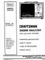
MODEL NO.
161.210400
CRRFTSHRN
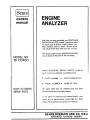
ENGINE ANALYZER
FOR 12& 24 VOLT SYSTEMS
Caution:
. OPERATING INSTRUCTIONS
Read Rules For
Safe Operation
• SAFETY
and Complete
Operating Test
Procedures
RULES
• TUNE- UP PROCEDURES
Carefully
• REPAIR PARTS
............
•........
. .....
,,
,,,,
,
,,
,,,,,,
,
,I
..........
'
I I
II
SEARS, ROEBUCK
CHICAGO,
PRINTED iN U.S.A.
Illl
11 IIIIIII
IIII
11
AND CO. U.S.A.
ILLINOIS
6068.4
......
2-17070_
TOT
Numld
TEST lll!lii(l
34€-*Lo_
v_XAG[ OnOP
T(STS ................................
ST
T[S? _UHO_X _I_--E|SStOII
COtI_O. $#;1_
TIE.los .....................
S2
!£ST llli_l
?_ST liilli_l
HF-_
TEst m, ilIl lii--l[Ai
TEST _U_ER
illIIlllNGS ........................................
Wlli!lOi lffN'OtTil IIlD
t8
............................
!!
_4B--ELEC?NICAL
iIRIN_ltARNE$S .............................
_9
tEPt.ACfi,I_
R(ILAc[,MENI
e,',_T_LIST .................................................
$t
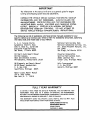
IMPORTANT
The information
in thls manual will serve as a generaJ gulde for engine
tune-up and charging system tests and adlustments.
CONSULT THE VEHICLE SERVICE MANUAL FOR SPECIFIC TUNE..UP
INFORMATION
AND TEST PROCEDURES. ALWAYS FOLLOW THE
MANUFACTURER°S
SPECIFICATIONS AND TEST PROCEDURES FOR
ADJUSTING DWELL ANGLEe IDLE SPEED AND CHARGING
SYSTEM
OUTPUT, ESPECIALLY VEHICLES WITH MODERN ELECTRONIC
IGNITION AND EMISSION CONTROLS.
DO NOT ATTEMPT TO
SERVICE VEHICLE WITHOUT MANUFACTURER'S
INSTRUCTIONS.
The following Is a list of publishers who have service manuals available for your
specific vehicle at a nominal cost. Write to them for availability and prices, specifying
the make, style, and model year of your vehicle.
A. E. A. Tune-Up Charts
Automotive Electric Assn.
130i W. 22nd St., Suite 202
Executive Plaza Building
Oak Brook, Illinois 6052%
National Service Data Book
National Automotive Service, Inc.
Div. Glenn Mitchell Manuals, Inc.
Box 10465
San Diego, Ca]ifornia 92110
Chilton_s Auto Repair Manual
Chllton Company
56th and Chestnut Streets
Philadelphia, Pennsylvania 19139
Chrysler Corporation
Service Publications Dept.
26001 Lawrence Ave.
Center Line, Michigan 48015
GM Diagnosis and Repair Manual
GM DR Manual Headquarters
P. O. Box 1185
Southfield, Michigan 48075
Helm Incorporated
P. O. Box 07150
Detroit, Michigan 48207
Motor's Auto Repair Manual
250 W. 55th Street
New York, N. Y. 10019
FULL 1 YEAR WARRANTY
IF, WITHIN 1 YEAR FROM THE DATE OF PURCHASE, THIS AUTOMOTIVE
TEST
INSTRUMENT
FALLS DUE TO A DEFECT iN MATERIAL
OR WORKMANSHIP,
RETURN tT TO THE NEAREST SEARS STORE THROUGHOUT
THE UNITED
AND SEARS WILL REPAIR OR REPLACE iT, FREE OF CHARGE.
STATES÷
THIS WARRANTY
GIVES YOU SPECIFIC LEGAL RIGHTS, AND YOU MAY
HAVE OTHER RIGHTS WHICH VARY FROM STATE TO STATE.
SEARS, ROEBUCK AND CO,
DEPARTMENT 898/731A
SEARS TOWER
CHICAGO,
IL 60684
ALSO
Wage
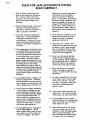
RULES FOR SAFE AUTOMOTIVE TESTING
READ CAREFULLY
Read this Owner's Manual and these
comportment€ontaining charging bat..
terles should be well ventilated to
prevent accumulaHon of explosive
gases. To avoid spark_, do ru_tdisturb
the battery charger connectlonswhile
battery is charglngs and always turn
charger off before dlsconnecti_'gthe
battery clips. When removing or reconnecting battery cables, make sure
Ignition switch and all acce.orles
are
turned off.
Rules for Safe Automotive Testing corefully.
Fa_iure to Follow instructions
and safety _ies could result tn serious
bodily _nlury and/or damage to the
Instrument.
Beforestarting the englne_ set the park.,
Ing brake and place gear selector In
NEUTRAL an standard transmissionsor
PARK on automatic transmission.
2_
The carbon monoxide in exhaust gas is
highly toxic.
To avoid asphyxiation,
alway_ operate vehlcle In a well..
ventilated area. if vehicle Is In an enclosed arean exhaust should be routed
3_
dtrectly to the outside via leakproof exhaust hose.
e
,
B
When operating any test instrument from
on auxiliary battery+ connect a jumper
wlre between the negative terminal of
the aux_llary battery and chards ground
on the vehicle under test for negative
ground systen_h For positive ground
systems+connect the jumper wire to the
positive terminal of the auxll _ary battery
and chosdsground an the vehicle.
When working in a garage or other enclosed area, auxii la_ battery should be
located at least 18 Inches above the floor
to minimize the potsibllity of spork_
;gniHng gasoline vaporsand causlng an
explosion.
An automobile battery Is €apable or pmduc|ng very hlgh currents. Therefore,
exercise reasonable care when working
near the battery to avoid electrical connections through tools, wristwatch, etc.
Avoid contact with battery electrolyte.
It can eat holes In clathlng,
burn skin
and cause permanent damage to eyes.
Always wear q_iash proof safety goggles
when working around the battery,
if
battery electrolyte
is splashed in the
eyes or on skln, immediately flush the
affected area for 15 minutes with large
quantities of clean water.
In case of
eye €ontact0 seek medical a_d,
e
The gasesgenerated by a chargtng bat-.
tory are highly explosive. Do not
smoke or permit flame or spark to occur
near o battery at any tlme+ particularly when it Is charglng. Any room or
v
9_
Never add acid to a battery once the
battery has been placed In service.
Doing so m_y result in dangerous
spattering of electrolyte o
Keep hanch, halr_ necktie, loose
clothing and test leads well away from
fan blade, fan belt_ power steering
belt, air conditioner belt and other
moving engine parts_ as serious injury
could result from entanglement.
10. Do not touch hot exhaust manifold,
radiator or hlgh-voitage spark plug
and coil ter_nlnals. Spark voltages ore
nat normal ll) lethal but an tnvotuntmy
lerk of the handsor armscaused by
electrical shock m_ result in Injury,
II.
Never took dlre:tly Into carburetor
throat while engine is cranking or
running. A sudden backfire can cause
serious burns.
i2.
To avoid the possibility of a flash fire,
do not smoke or permit flame or spark
to occur rear carburetor_ fuel line+
fuel filter, fuel pumpor other potential sources of spilled gasoline or
go$ol|ne vapors.
13. Never remove radiator cop while the
engine is hot.
Hot €oolant escaplng
under pressure can cause serious burnt.
14. The jack supplied with the vehicle
shou|dbe used on|y for changing wheels.
Never crawl under car or run engine
while vehicle ls on iack.
15. When making electrical
test connec-
tions to the vehicle, do not use the
carburetor or other fuel system components as a ground connectlon_ as a
spark could lgnffe the gasoline vapors
and cause a fire or an explosion.
_ge
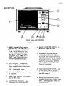
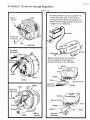
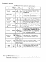
DESCRIPTION
FRONT PANEL AND CONTROLS
FIGURE I
I •
METER. Provides following scalesLow Ohms X 1, 0 to 1,000 Ohms (10
Ohms center scale), HI Ohms X
1,000, (10,000 Ohms center scale)t
RPM Hi 0-6000, Lo 0-1200 RPM,
Volts 0-i6 Lo, 0-32 Hi. Dwell 8
6.
BLACK - OTHER TESTS SOCKET. Insert BLACK plug on test lead.
OTHER TESTS SELECTOR SWITCH.
•
Always place switch In CENTER position for all tests, indlcoted
by functlon
cyl. _)-45 a , 4 cy!. 0-90 °, 6 cyl.
0-60 , Amps, Parers 0-3.2 Volts1
AIte rnator-good/defective
zones.
switch (No.B)
above.
tlon for charging
Use left hand posl-
Amps and right
positton for starting Amps.
slowly
rotate
right
line.
this plastic
slotted
ALWAYS
return switch to center posltlon when
ZERO ADJUSTER.
Meter painter
adjustment, if pointer is not on zero,
e
hand
Amp$ test is completed.
screw
or left to set pointer on zero
Check before testing.
.
FUNCTION
SELECTOR SWITCH.
Used
to select meter range for each test.
.
RED AMPS SOCKET.
on Amps lead.
WHITE
4_
plug
e
OHMS
on Ohms
described
SOCKET.
of each test function
is
on page 4.
Insert WHITE
lead.
.
BLUE RPM PICK UP SOCKET.
Blue plug on inductive
A description
Insert RED plug
pickup
Insert
lead.
RANGE
SELECTOR SWITCH.
Select
for HIGH or LOW scale range for VOLTS,
RPM, or OHMS depending on the test
being performed.
J
Function Selector
Alternator
RPM InducttveTach
m
m
D
Volts__,
well
Points m
FUNCTION
FIGURE
POINTS.
3.2
Volt
_ Ohms
SELECTOR
SWITCH
POSITIONS
2
4.
Lo scale-provldes
RPM.
.
i200
or 6000
RPM
point condition on scale.
Also used
for locating voltage drops in elect..
engine speed reading.
Page 3. Use Lo-i200
rlcal
all Lo speed carburetor idle tests
and Hi- 6000 RPM range for high
starting
and charging
system.
speed
m
Provides
VOLTS.
Used to Indicate battery
charging and starting cor_ditlons.
Use 16 volt Lo scale for t2 volt systems_
and 32 volt (HI) r_ale for 24 volt
systems•
ALTERNATOR.
condition
Indlcates
on GOOD
5.
DWELL.
electrical
It w(ll
dwell
HI
& Lo -
resistance
used to measure
in Ohms,
on
ignition cables, ballast
resistOrSeor
ignition coil windings.
Select HI or
Lo position.
See Item 19 Page 3.
detect open or shorted diodes or
windings.
IMPORTANT:
Used to check point
OHMS.
.
or DEFECTIVE
..................................................
tests.
on breaker polnt ignitton
systems.
Read 45 ° scale fo[ 8 cvi.o 60 ° scale
for 6 cyl, and 90" scale for 4 cyt.
engines.
alternator
sca'te wlth englne running.
See item #9
RPM range fat
i i i
iiillll
illrlll[ i iii
ii
...................................................
The above function
NOT
WORK
tests selector
tests will
on meter unless other
sw(tch4,
ITEM
Nc. 7 Page No. 3) Is in CENTER
POSITION
for OTHER TESTS.
NOTE:
The Ohms test operates from an
internal 9 volt battery and ;ncorperates
automatic Internal zero calibration.
No external zero adjustment ;s required.
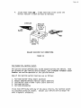
IGNITION
KIT
J
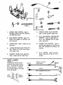
ACCESSORIES
FIGURE 3
BATTERY POST ADAPTER.
I.
electrical
systems
and 400 Amp
Used in
tests with
4t
.
SPARK PLUG
Used to make ignition
................................................
'
TEST
FIGURE
sys-
.
..........................
COIL
H.E.i.
Dwell
ADAPTER.
easy hook-up
tems with
necHons.
tests.
_'_ .....................
PRIMA!RY
provide
ADAPTER.
cable
tests.
insulated
ADPTER.
connection
Used to
on ignLtion syscall
primary
con-
Used to provide
on G.M.H.E.I.
systems.
Itrtrnlnrlrllllllrlrlll
.................................................................................................
LEADS
4
The plugs and sockets are polarized to insure correct attachment.
cable
G.M.
cars equipped with the diagnostic connector.
ALTERNATER FIELD PLUG CONNECTOR. Used in "A" & "B" circuit alter-.
nator output tests.
DOMESTIC
ADAPTER.
G.M.
DIAGNOSTIC
CONNECTOR.
ADAPTER. Used to make tests on
9_
5_
PLUG
shunts.
JUMPER LEAD. Used in electrical
tems tests.
d
SPARK
Used to make ignition
i00 Amp
SIDE MOUNT ADAPTER. Used with
Battery Post Adapter on batteries with
side terminals.
2_
FOREIGN
POINTS,
VOLTS,
j
_m,._
BLACK
AND
DWELL
...................
_.,_,,_ _,_
The socket has a groove
on each top corner.
The plug
has a mating ridge on the inside
RED
AMPS
....
of the top corners.
r*
LEAD
_
PANEL
PLUG
k_
SOCKET
_WITH
_"b'
'-'_': ::':'100/400
.......
AMP"
' _'SHUNT'"
BLUE
RPM
_m,..
WHITE
OHMS
_--
I_€;
v_,a_,.,/l_ll_lr'1_,.
BREAKER
I,,
3.
CONVENTIONAL
METER ZERO ADJUSTER.
necting
2.
POINT
any
test
leads,
meter
po_nter zero
zero,
slowly
rotate
I IUI_I_'.'_
Before
always
position,
con-
with
on
and set point-
LEADS.
test
three
Attach
,
spark
DO
,
10.
Connect
atlve
(-)
BLACK clip
GRD
plug
cable
pickup
as close
,Jaws
to a
to dlstrtbumust be
cc_nect
OHMS
I
clip.
Starter Amp shunt must remain closed
at all times except for charging system test as indicated.
Damage to
Battery Adaptor can occur if the
above instruction is not followed,
neg-
terminal,
JAWS
NOT
Engine must be at operating temperature before testing,
Proceed with tests
as outt_ed
in this manual.
positive
to battery
RPM induction
leads
Install battery post adapter on the
negative
ground battery
terminal as
shown.
5.
the GREEN clip to the dis,.
termlnai on call primary.
tar cap as possible.
fuliy closed.
9.
Connect
RED clip to battery
(+) termlnal,
SYSTEMS
Connect
tr_butor
6_
into matching
color sockets on panel.
Connect leads as illustrated
below.
4,
I r..,.._ t O
IGNITION
pro-
per size flat screwdriver
er on zero line.
insert all
r-t_l_C.lll_iL
check
if not
adjuster
run
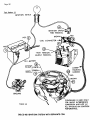
MUSTCLOSE
SO
UPPERAND
LOWER
yPLUG
PoLE
P,ECES
TOUt.
ACH'o'r.ER
®
WIRE
THIS
TO
E
GAP
TACH PICK-UP MUST BE AS
CLOSE TO DISTRIBUTOR CAP
AS POSSIBLE
tEEN
CLOSE STARTER
SHUNT FOR
STARTERAMPS
OPEN FOR
CHARGING
AMPS
FIGURE
®
TO GROUND
ON ENGINE
RED
iSE NUTS MUST
BE TIGHTENED WITH
A WRENCH.
_-_
TI
EN
THIS SCREW
I'O STARTER AND
ALTERNATOR
RED
SCREW POST INTO BATTERY
TERMINAL BEFORE INSTALLI
BATTERY POST ADAPTER,
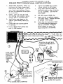
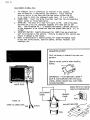
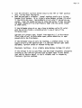
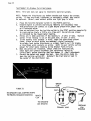
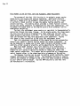
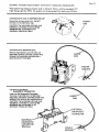
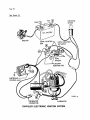
CONNECTIONS
FOR ENGINE TESTS
ELECTRONIC
IGNITION
SYSTEMS
Connect test leads as instructed
Proceed with tests as outlined in this
manual--Oral fling those tests which
apply only to BREAKERPOINT SYSTEMS
on
previous page for BREAKER POINT
systemsand as illustrated below with
the following exception; See Test Number
15 far proper connection of the GREEN
clip.
Engine must be at operating
before testing.
Always
starting
temperature
close starter shunt b6fore
engine.
SEE PAGE No. 6 FOR NUMBER IDENTIFICATION.
®
_PLUG
WIRE TO
BE
JAWS MUST CLOSE SO UPPERAND LOWER
POLE PIECES TOUCH EACH OTHER
i
BLUE
_LACK
RED
CLAMP TACH PICK-UP MUST BE
CLOSE TO DISTRIBUTOR CAP AS
POSSIBLE
IEEN
See Test
Numbe r 1.5for
connection
CLOSE
STARTE_
SHUNT
FOR
STARTER
AMPS
OPEN
FOR
CHARGING
®
DISTRIBUTOR
STRIBUTOR MAGNETIC
_ICK-UP CONNECTOR.
AMPS
_.__
)BLACK
®
GROUND
ON
ENGINE
NUTS MUST
BE TIGHTENED WITH
EN
A WRENCH.
THIS SCREW
STARTER AND ALTERNATOR
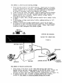
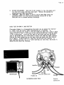
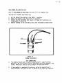
Test
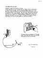
Number
1--Startin_
and
Crank ing_Vg.!tage,
I.
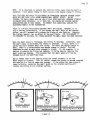
Place function switch in the VOLTS position.
Engine must be disabled
to prevent Starting for this test.
On ELECTRONIC IGNITION, disconnect
battery cable at coil or unplug pickup coil connector at distributor
or ground HT secondary lead on any external coil system.
,
2.
3.
Close starter amp shunt (See page 6, Figure 6) before operating starter.
Have an assistant turn the ignition switch to the START position and
operate starter for 15 seconds.
Observe battery voltage reading
with engine cranking, (Figure 8).
A battery in good, fully charged condition should read a steady 9 volts
or more.
If the battery voltage reads below g volts, recharge battery to full
charge condition.
Excessive fluctuating voltage reading (over i volt) can be caused
by a starter in poor condition due to worn bearings, dirty commutator,
a defective battery or corroded starter cables,
Clean, tight connections are a must throughout the starter system.
4.
5.
6.
STARTING AND CRANKING
VOLTAGE TEST CONNECTIONS
FIGURE B
BA TTERY V OLTS
RED
CLIP
BLACK
CLIP
SOLENOID
L
TERMINAL"S"
GR
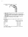
Test
I.
2.
Number_2-,Starter
BATTERY
Current
STARTERMOTOR
ENGI)UND
NE
Draw
Place center slide switch to the right hand starter amps position.
Operate starter and note starter current on the 400 Amp scale, (Figure 10),
Compare to specifications.
IMPORTANT--Always
return switch to center
position for other tests when amps reading is compieted{AZ_o _¢e F_gu_e 15J.
If battery-starter test is normal (a steady reading over 9 volts),
proceed to Test Number 4_Cha_gingS_stemVg]tage
and Current.
Page 9
CLOSE STARTER
SHUNT FOR
STARTER AMPS
OPEN FOR
CHARGING
AMPS
BLACK
v
TO GROUND
ON ENGINE
RED
NUTS MUST
BE TIGHTENED WITH
STARTERAMPS
A WRENCH.
TIGH!
v
THIS SCREW
STARTERAND ALTERNATOR
S_t_
C_r{nt
.,c_it_h Po_Z_Zon
FIGURE 10
Conn_c_on_
For S_J_uzt_.ng il C,ho_rg_ng
CuArent Measurements
FIGURE g
Test
Number 3--Starter
Circuit
Voltage_..Loss
I.
Disconnect all tester leads. Use only the BLACK PLUG battery-dwell
lead for this test. Use the BLACK and GREEN test clip for voltage
loss tests.
2. Place function switch in POINTS position and read 3 volt points
scale. Each division is .I volt.
3. Disable engine to prevent starting by grounding HV iead of the coil
as shown below. On HEI or electronic systems disconnect battery
lead at coil or unplug distributor pickup coil connector.
4. Refer to starter system illustrated below. Connect GREEN and BLACK
clips across each section of circuit shown by numbers (i-2-3-4 etc.).
5. All readings must read .2 volts (2 div) or less for normal conditions.
Reverse test leads if meter reads backwards.
6. High readings will be caused by corroded or loose connections at
battery terminals, cables or a worn solenoid.
®
Connect_Lon,s For Vo.&_ge
Lo_S M_asu_r_ments
FIGURE 11
®
STARTER
va_
iu
7,
8.
g.
10.
Remove and clean battery terminals and cable terminals in a warm
water solution with baking soda to dissolve corrosion, Tighten nuts
on starter solenoid terminals. Readings below B volts at the starter
usually indicate a defective starter cable or burned solenoid contacts. Replace defective parts as required for good starter performance.
Replace worn or corroded cables as required to correct condition.
Do not crank for mor_ than 15 seconds at a time, Allow starter
motor to cool off for 30 seconds between tests,
When tests are completed, reconnect coil for normal starting.
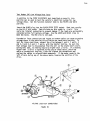
The function of the charging system is to keep the battery In an optimum
state of charge, to provide the necessary current to start the engine,
and operate the electrical systems when the engine is running. The
battery is charged by an alternator that is driven bye belt connected
to a pulley on the engine crankshaft. The alternator generates an alternating current (A, C. ) that is converted by internal diodes Into direct
current (D. C,) to charge the battery, A regulator is needed in the
charging system because the alternator output voltage increases as the
engine speed increases, The regulator keeps the alternator output voltage
at a safe upper limit so the battery will not be overcharged and the
headlights and accessories will not be damaged by excessive voltage.
I.
2.
3.
Place function switch in the VOLTS position. The Center Slide Switch
must be in the OTHER TESTS position.
Slide the RANGE SELECTOR switch to the LOW range(O-16 volts) for
12 volt systems or to the HIGH range (0-32 volts) for 24 volt systems. Read test results on the appropriate VOL_S scale.
Be sure the shunts are in position on the Battery Amps Adapter as
shown in Key No.I Page 5, before starting the vehicle.
CAUTION: TIGHTEN ALL NUTS ON THE BATTERY ADAPTOR FIRMLY WITH A WRENCH
TO AVOID EXCESSIVE HEAT AND POSSIBLE SHUNT DAMAGE.
4.
Before performing Step 5, start the engine and allow it to run for
10 to 15 minutes or until the engine compartment is warm, then shut
it off. In order to obtain proper results from this test, the
battery must be partially discharged. To accomplish this, switch
on the headlights and put the blower on HIGH for a minimum of one
minute, or remove the distributor wire to prevent the car from
starting and crank the engine for about 30 seconds, then follow step 5,
5, Start the engine. Operate at a fast idle (approximately 1500 RPM).
Open the starter amps shunt. Note the battery charging voltage. The
meter should read over 12 volts and slowly rise to regulated voltage
in a few minutes (15 I/2 volts maximum).(Figure 12)
6. Move the Center Slide Switch to the CHARGING AMPS position and note
the alternator charging rate compared to vehicle specifications.(Figure 12)
Shortly after starting, an alternator in good condition should charge
from 50 to 80% of its rated capacity, and slowly decrease as the
battery regains its charge. The charging voltage will slowly rise
as the ampere rate decreases and maximum regulated voltage Is obtained.
7. Move the Center Slide Switch tO the OTHER TESTS position again for
voltage reading and operate the engine at fast idle until the
charging voltage stops increasing. Note the maximum voltage and compare
to vehicle specifications.
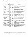
8. If the charging voltage exceeds IB I/2 volts
or as specified, replace
or adjust the voltage regulator. If the voltage reading is too high,
the defect could be:
Page 11
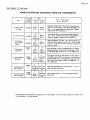
DEFECT
ACTION
A.
High resistance in the ground
circuit
Clean and tighten all ground
connections
B.
Regulator set too high
Adjust to the proper setting
(If adjustment is possible)
Most late model vehicles use
a regulator which is of solid
state design and cannot be
adjusted. These must be replaced when they are defective,
C.
Defective regulator
Replace Regulator
if the voltage reading is too low, the problem is either in the alternator,
regulator, or the battery.
9.
10.
CHARGING
AMPS
If charging voltage DOES NOT slowly INCREASE, this may indicate a
defective alternator. Rotate the Function Switch to the alternator
position, turn lights on and operate the engine at approximately 1200
RPM. Read the aiternator scale. A reading in the gray defective
zone indicates defective diodes or windings in which case the alternator
diodes and windings are functloningproperly.(Figure 12).
If a low or no charging rate is indlcated, check alternator output
under full field conditions by removing voltage regulator control
action. (See pages 12& 13 for connections.) To apply full field
voltage for maximum output, refer to vehicle specifications to
determine whether type "A" or "B" system is used for proper field bypass
connections.
ALTERNA TOR
CONDITION
om,Vw_,m
ALTERNATOR
RED
CLIP
BLACK
CHARGING
V OLTS
ENGINE
GROUND
VEHICLE
12 VOLT
WIRES
TO REGULATOR
BATTERY
FIGURE 12
"J_'/
CHARGING
AMPS & VOLTS
Page 12
IIATTERY _ft
AOAPTI[R CONNtCtlONS
ItOlt ALTERNATOR Tilt
CHARGING
ot_,r_
AM ,s
gill
FIGURE
NOTE:
zero
13
If the AMPS indicates
(left) during
STARTING,
FIGURE 14
V
reverse
CHARGING
below
or
the leads as
shown,
Caution:
FIGURE
DO NOT
pull
necessary_ grasp the
tO remove it,
on the wires,
terminal
with
if
pliers
"A" CIRCUIT
FIGURE 15
Remove field
the alternator
Field
(Electronic
Regulator)
lead (green wire) from
field terminal.
Connect
iumper wire from the alternator
terminal
to ground.
Battery
Insert screwdriver
field
additional
FIGURE i7 A
adapter
not more than I
is needed.
Tab
FIGURE 17 B
End
Lead
Plug
(Green
Wire)
Voltage
inch in end frame hole, ground tab
to frame with screwdr;ver.
No
Output
Terminal
Remove
16
Frame
\
Hole
Field Terminal
(Horizonhal)
Field
Jumper
CHRYSLER
JJL ......
Connect Jumper
to ground
Terminal
(Vertical)
(Blue Wire)
DELCO
_.....................
Remove cap from the field
terminal.
Connect jumper
wlre to field terminal and
ground.
Ground
Terminal
Stator
Terminal
!
FIGURE
Field
17 C
Remove Cap
Term;hal
Regulat_
Terminal
INTEGRAL
FORD
DESIGN
Regulator Exclte' Terminal
(to Ignition Switch)
Ground with
Jumper Wire
i'_e
"B" CIRCUIT
( External
Voltage
Regulator)
FIGURE 18
....................................................
II II]llllllnll
Battery
Term _nol
I IIIIIIIIII
II .................
r
On some vehicles if may be inc_onvenlent to
connect the iumper wlre at the alternator.
Jumper
Im such a iftuaHon remove the regulator connector from the voltage regulator and €onnect
a iumper wire as illustrated.
Plug
C HR YS LER
bisconnect
ignition
F_eld Lead
Remove field
Te
lead from field terminal.
Connect iumper w_re from positive
terminal of battery to the field lead.
_1
DELCO
Stator
_"_\
Di,conoe=t/
Jumper
/
__./7,_
Battery,
Ignition
Switch
Field
F;et
Jumper
Batter
Gr°umd__B_attery
FORD
........................................................................
Term;hal
1111111111111111111111111111111111
"
Regulator
Commector
Field
Stator
13
ru_E
_
I.
Be sure the shunts are tightly secured to the Battery Amps Adaptor
as shown in Key No. I Page 5 , and the Function Selector Switch is
placed in the Alternator position.
CAUTION: TIGHTEN ALL NUTS ON THE BATTERY ADAPTOR WITH A WRENCH TO
AVOID EXCESSIVE HEAT AND POSSIBLE SHUNT DAMAGE. IF YOU ATTEMPT TO
START THE ENGINE WITH THE SHUNT DISCONNECTED, THE 1/40HM RESISTOR
MOUNTED ON THE BATTERY ADAPTOR MAY BLOW OUT.
2.
3.
4.
Start the engine, then carefully disconnect the slotted ends
of the shunts as shown in the figure below. Turn the headlights
on and operate the engine at approximately 1200 RPM and observe the
alternator condition scale.
A reading in the RED GOOD ZONE on the meter indicates that the
alternator windings and diodes are satisfactory.
A reading in the GRAY DEFECTIVE ZONE indicates that one or more
diodes are open or shorted or that the stator winding is open or
shorted to ground or has shorted turns. Refer to Tests 9 and 10
Alternator Diode, Statorand Rotor Tests for further testing.
IMPORTANT: Refer to vehicle specifications to determine whether type
"A" or type "B"system is on the vehicle, Also check the rated output of
alternator on the nameplate or specifications listing,
1.
2.
3,
4.
5.
To perform this test, it is necessary to ground the field in the
type A Circuit or remove the regulator from the charging system and
energize the field in the Type B Circuit. This provides full field
operation and the alternator will charge at its maximum rated capacity,
Place the FUNCTION SELECTOR Switch in the VOLTS position and slide
the Center Slide Switch to the AMPS CHARGING position.
On the Type A Circuit, ground the field as shown on page 12, proceed
with Step 5 below.
On the Type B Circuit, disconnect the wiring harness plug from the
regulator and energize the field as shown on page 13.
Before starting the vehicle, be sure the shunts are connected to the
Battery Amps Adapter as shown in Key No. I on page 5
• Turn
on the headlights and set blower speed to high. The meter should
read to the left of zero or "backwards". If it reads up scale, reverse the shunt connections as shown in Figure 1 5.
Turn all lights and accessories "OFF". Start the engine and operate
it at the speed recommended by the manufacturer for alternator
output test. Unless otherwise specified, adjust engine speed as follows:
Chrysler
GM-Delco-Remy
Ford
1250 RPM
2500 RPM
2900 RPM
Page 15
With the engine running, carefully open the starter shunt as shown
in Key 10 on page 6 .
Observe the current (amps) reading on the
0-100 Amps scale, reduce engine speed to curb idle and compare meter
reading with the manufacturer's
specifications.
ALTERNATOR FULL FIELD
NOTE: To determine the actual output current, add 5 amperes to the meter
reading obtained during the output test. This is the approximate current
used by the ignition system, dash instruments and alternator field toll
combined which does not reach the battery to be measured during
this test. If the meter reading is at or higher than specified, the
alternator output is satisfactory. If the meter reading Is less than
specified, a loose or worn alternator drive belt, a faulty field or
battery wire to the alternator, or a poorly grounded or defective alternator
is indicated. If the meter reading is to the left of zero, a broken
field wire or a defective alternator is indicated. (Meter reading is the
battery discharge current used by the ignition system and dash instruments.)
6.
When test is completed, shut off the engine, disconnect jumper lead,
remove the shunt, and reconnect wiring harness plug, connector or
field wire to the regulator for normal operation,
Repeat Test Number 4:±Charging System Vp]tage and Current
If the voltage reading is within the range as specified by the vehicle
service manual, (typically between i3.8 and 15.2 volts on 12 volt systems,
and 27.6 and 30.4 on 24 volt systems) the regulator is satisfactory.
If the voltage reading is out of specifications but satisfactory
operation was obtained on the CHARGING SYSTEM VOLTAGE AND CURRENT and
ALTERNATOR CONDITION tests, the voltage regulator should be adjusted
(if possible) or replaced.
Test Number B--Battery
Repeat Test Number4-,ChargingSystemvo]tage
and Current
After the VOLTAGE REGULATOR--TEST 7 is completed, the regulator should
be functioning satisfactorily, leaving the battery as the only untested
component remaining in the CHARGING SYSTEM. To test battery condition,
attach the shunt to the BATTERY POST ADAPTER (Key I
Page 5 ), start
the engine, and operate it at approximately 1200 RPM. If the voltage
reading is less than 13.8 volts, check the water level in the battery and
fill to the proper level, if necessary. Charge the battery and repeat
this test. if the voltage reading is still low, the battery is defective
and should be replaced.
Page 16
Test
1.
2.
3.
Number 9--Ohms
Test
The ohmmeter test is powered by an internal
9 volt
battery.
No
zero calibration
is required
by the operator.
Place Function
Selector
Switch in the Ohms position
and select
either
the Hi
or Lo range to match the component under test.
(X i or X lOOd)
CONNECTIONS: Insert
the white Plug Ohms Lead into the corresponding
tester
socket as illustrated
below.
OPERATION: The meter will
read full
scale at INF.
with cllps,open,
and when the clips
are connected together
will
read zero on the
left.
(See Paragraph #6.)
To measure resistance,
connect the clips
to the component to be tested and read the prope_ Ohms scale.
(X 1 or
x 1ooo)
4.
5.
IMPORTANT CAUTION: ALWAYS disconnect ALL L£ADS from any electrical
part to be tested on the vehicle. Failure to observe this caution may
result in damage to the tester.
Refer to manufacturer's specifications for normalresistance value
of any part being tested, ignition cables, ballast resistor, coil
windings, etc.
OHMMETER BATTERY
The 9 volt
battery
ts located
in the rear com-
partment,
Observe correctt polarity when installing
battery.
IMPORTANT:
9 VOLT BATTERY ( SEARS #
64i7) IS NOT SUPPLIED WiTH THIS ANALYZER.--OHMS CIRCUIT WILL NOT WORK
WITHOUT BATTERY.
WHITE PLUG
I
OHMS TESTS ON VARIOL
VEHICLE COMPONENTS
i
SECONDARY
OHMS
PRIMARY
OHMS
1
FIGURE 19
OHMMETER
CONNECTIONS
RED
FUSE
BA LLAST RESISTOR
BLACK
COIL
Page 17
6.
7.
BATTERY REPLACEMENT. When the g volt battery is low, the meter will
not read full scale with the clips open. Replace the battery to
obtain accurate OHMS measurement.
IMPORTANT: When the tester is not in use or when Ohms tests are
completed ALWAYS turn the Function Selector Switch OUT of the
Ohms position to prevent battery discharge.
DIODE TESTS ON OHMS X 1000 POSITION
Alternator diodes in a disassembled alternator can be tested for "shorts"
or "opens" with the stator leads disconnected as illustrated. To
facilitate checking the diodes in the end frame and heat sink, place a short
length of wire or nail in the jaws of the RED and BLACK test clips as shown
in the illustration. Touch the RED lead to the diode case and the BLACK
lead to the diode lead as illustrated in Step A and note the meter reading,
Reverse the lead connections on the same diode and again note the reading
as in Step B. A good diode will have one low and one high reading, if
both readings are very low, or if both readings are very high, the diode is
defective and should be replaced.
LACK
RED
RED
WHITE PLUG
Initial
FIGURE 20
ALTERNATOR DIODE TESTS
Connection
STEP
See steps 1-7 TestNumberg--OhmsTest
for Ohmmeter use
ROTOR AND STATOR TESTS ON OHMS X 1000 POSITION
Rotor-The alternator rotor may be tested for open or grounded field coils. To
check for opens, touch the test leads to each slip rJng. If the meter
reading is near zero, (left end) the winding is not open. If the meter
shows high reading (extreme right end of the scale), the winding is open
and the alternator should be repaired or replaced. To check for grounds,
touch the test leads from either sllp ring to the rotor shaft or to the
rotor poles. If the meter shows only a slight reading or none at all,
the field winding is not grounded. If the meter reading is near zero
(left end), the winding is grounded and the alternator should be repaired or replaced.
Stator-The alternator stator windings may be checked for grounds or opens. Disconnect the three stator leads from the diodes before any test. To check
for opens, successively connect the tester leads between each pair of
stator leads. In each case, if the meter reading is near zero (left end),
the windings are not open. If the meter shows a high reading, the winding
is open and the alternator should be repaired or replaced. To check for
grounds, connect the tester leads to each stator lea_ and to the frame.
If the meter shows a full scale reading, the stator is not grounded, if
the meter is near zero (left end), the stator winding is grounded to the
frame and the alternator should be repaired or replaced.
The purpose of this test is to confirm the presence of supply voltage to
the positive (+) or Battery (Bat) terminal of the Ignition Coil. NO
VOLTAGE AT THIS POINT RESULTS IN A "NO START" CONDITION,
Perform this test as follows:
lm
2.
Place the Function Selector Switch of your Craftsman Analyzer in the
VOLTS position. Place the RANGE SELECTOR in the 0-16 volts position.
Insert the BLACK OTHER TESTS lead in its corresponding socket on the
Analyzer. Connect the BLACK clip to a good vehicle ground such as
the engine block or negative (-) battery post. Connect the RED
clip to the to the positive (+) or battery_at) terminal of the i__
Rnition coil. In the case of the General Motors HEI Syste_,,disconnect
_-e_Tn_ttery
(Bat) lead at the Distributor (on Integrai Coil
Systems) or at the coll (on External Coil Systems). Insert the GM
Diagnostic Connector, Page 5 , Key No, 7 into the socket of this
disconnected wire and connect the RED clip to the adaptor.
IMPORTANT: DO NOT ALLOW THIS CONNECTION TO TOUCH GROUNDI
IS NOT USED.
THE GREEN CLIP
Page 1_
3_
4.
Turn the vehicle's Ignition Switch (key) to the "ON" or "RUN" position
only. Do not start the engine.
Read the analyzer's voltmeter. Normal readings should be as follows:
Breaker Point Systems: At or slightly below battery voltage (12 volts)
if the points are open. Approximately 6 to 8 volts if the points are
closed, "Jog" the engine quickly to close the points if they are open.
The meter reading will be significantly lower with the points closed
as shown above.
If the Voltmeter stays at or very close to battery volts (12 volts)
with the points closed, a problem exists in one or more of the
following areas:
Ignition coll primary open, Pigtail from negative (-) or Distributor
(Dist) side of co11 to distributor open, points defective, or open
ground within the Distributor.
If the Voltmeter stays at.zero (no reading), a problem exists in the
supply circuit to the ignltion Coil i.e. ballast resistor open (when
equipped), ignition switch or related wiring open.
Electronic Ignitions:
At or slightly below Battery Voltage (12 volts)
If the voltage is not as specified, see the proper diagnostic procedures
relating to your vehicle ignition type as shown later in this manual.
Your vehicle service manual is also a valuable toot in diagnosing
Electronic Ignition problems.
Page 20
Test Number
NOTE;
12--Breaker
This test does
Point
Resistance
not apply
to Electronic
ignition
systems.
NOTE: Remove the distributor cap before testing and inspect the contact
points. If they are blued, blackened, or noticeably pitted, they should
be replaced. Normal, used contact points are light gray In color.
i.
Z.
Place the Function Selector Switch in the POINTS position. ,
Disable engine to prevent starting by removing coil secondary lead
from distributor and connect to a good engine ground with Jumper lead
as illustrated below.
Have an assistant turn the ignition switch to the START position momentarily
to crank engine slowly a little at a time until the points are closed
as indicated by the lowest meter reading.
Points are in GOOD condition if the reading is .3 volts or less. Replace
points if the reading is out of the good zone, or over .3 volts.
If the reading still exceeds .3 volts, check the distributor ground
plate, (plate on which points are mounted), pigtail extension
to primary lead inside distributor or primary lead to coil for breaks,
or misaligned point contacts on points. Refer to your vehicle service
manual for other tests relating to the Breaker Point Circuit.
When new points are installed, always clean and lubricate cam,
check again for contact alignment, and resistance, Adjust to
correct Dwell before startlng--See Test Number I 3, Dwell Adjustment.
Correct the defect and repeat the test. When the points check OK,
turn the ignition switch OFF. Reinstall the high tension lead in
the center of the distributor cap.
#
3.
4.
5.
6.
7.
GREEN
CLIP
FIGURE 21
DIST.
SECONDARY
COIL CONNECTIONS
TO PREVENT ENGINE STARTING
BLACK
CLIP
TO GROUND
ON ENGINE
PRIMARY LEAD
GROUND
ON
ENGINE
Page 21
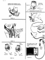
T.estNumber 13--Dwell Adjustment--Breaker Point S#s##m.s
1.
2.
3.
4.
Rotate the Function Selector Switch to the dwell position.
Consult your vehicle service manual to determine which vacuum hoses,
if any, should be disconnected and plugged prior to making dwell adjustment or test.
Run the engine at specified idle speed and note dwell reading on proper
4-6 or 8-cylinder scale to correspond to the engine under test.
Compare results to vehicle specifications_ adjust _o correct dwell
if required.
READ PROPERSCALE TO SUIT
NUMBER OF ENGINE
CYLINDERS
BLACK
RED J
CLIP
CLIP
GREEN
CLIP
_J
DIST.
BAT,+
COIL
_
DISTRIBUTOR
FIGURE 22
DWELL ADJUSTMENT CONNECTIONS
On engines that have a sliding window in the distributor cap, adjust dwell
as follows:
I.
2.
3.
Operate engine at specified idle.
Raise the window and insert a I/8" Allen wrench into the adjustment screw.
Turn the adjustment screw until the correct dwell is indicated on the
dwell scale.
Page Z2
NOTE:
Disconnect
omd plug the vacuum advance
llne from the disfr;butor.
If the vehicle
is equipped
with
t_o;d, disconnecf
end,
an advance-retard
solethe wire at the carburetor
WINDOW
1/8"
ALLEN
WRENCH
ADJUSTMENT
SCREW
GM TYPE
PLUG END OF VACUUM
LINE
FIGURE 23
FIGURE 24
On engines with non-window distributors, adjust the dweil as follows:
I.
2.
3.
4.
5.
6.
Stop the engine and remove €o11 wire from the center tower of distributor
cap. Connect the jumper wire between coll wire and engine ground to
prevent arcing while cranking the engine,
Remove the distributor cap and rotor.
Connect a remote starter switch to the vehicle or have an assistant
crank the engine for you with the ignition switch.
Turn the ignition switch on and with the engine_cranking, observe the
reading on the dwell scale.
To adjust dwell, loosen LOCKING screw slightly and adjust point gap by
turning ADJUSTMENT screw (Figure 25) or by inserting a screwdriver in
slotted hole (Figure 26 ) and turning the tool slightly left or right to
obtain the specified point dwell reading. Tighten locking screw and
recheck dwell while cranking engine. Repeat procedure if necessary.
Reassemble distributor and recheck dwell reading with engine operating
at specified idle.
.....................................
II1[[I
Slotted Hole
Breaker
Locking
Po(nf
P
Ga_
-
TYPICAL
INTERNAL
FIGURE 25
TYPE
BREAKER
ADJUS TMENTS
FIGURE 26
Lock|ng Screw
III
I[111['1[11
Page 23
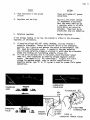
NOTE; It is important to recheck the ignition timing every time the dwell is
adjusted. A one degree change in dwell causes a one degree change in timing.
THIS TEST DOES NOT APPLY TO ELECTRONIC OR TRANSISTOR IGNITION SYSTEMS EXCEPT
DELCO HEI AND THOSE TYPES USING CONVENTIONAL CONTACT POINTS. ON HE1
SYSTEMS, THE DWELL ANGLE WILL BE LOW AT iDLE SPEED AND WILL INCREASE STEADILY
AS ENGINE SPEED INCREASES. IF IT DOES NOT, THE ENGINEMAY MISFIRE DURING
ACCELERATION AND AT HIGH SPEEDS. TO CORRECT THIS CONDITION, REPLAC_ THE
ELECTRONIC MODULE IN THE DISTRIBUTOR,
There is a direct relationship between dwell and timing. However, it is
only a one way relationship. If you change the dwell angle of the breaker
points, you will automatically change the timing of the ignition. Changing
the timing, however, has no effect on the dwell angle. FOR THIS REASON IT
IS IMPORTANT TO RE-CHECK THE TIMING WHEVEVER THE DWELL ANGLE HAS BEEN ADJUSTED.
When the dwell angle is increased, the timing is retarded. Conversely, when
the dwell angle is decreased, the timing is advanced. In fact, there is a
one-to-one ratio between dwell and timing. For every one degree change in
dwell, there is a corresponding one degree change in timing. This can
sometimes be used to make minor changes in timing. If, for example, it is
desired to advance the timing two degrees, it canbe done by reducing the
dwell angle two degrees. This assumes that the dwell angle will not be
changed out of its specified range.
Due to normal wear of the rubbing bloc_ the normal tendency Is for the
dwell angle to increase. This, of course, causes the _iming to become retarded
and results in a loss of power and econorRy, if the engine has been properly
tuned initially, restoring the dwell angle to its original setting will
restore the timing to its original setting.
I/
49. _
_o
//
'w°°
W;de Gap
TYPICAL
DWELL
8 CYL, ENGINE
_
SMALL
Small Gap
DWELL
ANGLE
CAUSES POOR HIGH SPEED
PERFORMANCE
FIGURE 27
LARGE
DWELL
ANGLE
CAUSES POINTS TO BURN
/
T_estNumbeF !4-_DwelI Variation Test
Repeat
Test Number 13, Steps
i-4
NOTE: This test does not apply to transistorized ignition systems (except
those types using conventional contact points).
I.
2.
3.
4.
Rotate the Function Selector Switch to the DWELL position.
Disconnect and plug vacuum advance hose(s) as described in DWELL
Angle Test 13 on page 21 and 2_
Operate engine at curb idle. ,,,lie observing DWELL scale for any
change in reading, increase engine speed to approximately 1500 RPM
and then return to idle.
Reconnect vacuum advance hose(s).
15
2O
25
I0
3O
35
40
5
0
,45
8(
FIGURE 28
DWELL VARIATION
Variation on 4, 6, and 8=cylinder engines should not exceed 3 degrees.
if it does, check for:
a. wear in distributor shaft
b. wear in distributor shaft bushing
c. wear in breaker plate
NOTE: Manufacturer's specifications for some engines call for the
distributor vacuum advance hose to remain connected during the Dwell
Variation Test. In this case, a maximum dwell variation of 6 degrees is
allowed unless otherwise specified by the manufacturer.
Test Number IS--Dwell Anqle--Electronic!gn!t!qnSystems
(Electronic Solid State or Transistor Ignition Systems)
General-Due to the vast array of electronic ignition and engine control systems
being used on late model cars, it is essential that specific service
information for the vehicle under test be obtained. Although Dwell
Angle is not adjustable on electronic systems, the reading obtained is
important and should be within the manufacturer's speclfled limits. If
it is not, consult the manufacturer's shop manuals for diagnostic procedures,
Preparation for tests-Before beginning tests, always check the zero adjustment of the instrument
as outlined under Description--Zero Adjuster, above. Attach the test leads
to the instrument and proceed to the section in this manual describing,
CONNECTIONS FOR TESTING the appropriate vehicle.
CONNECTIONS FOR TESTING
Ford-On Ford cars with 1974 electronic ignition systems, use the Ford adapter
pin as shown in Figure29, below. Connect the GREEN clip from the Craftsman
Engine Analyzer to the adapter pin. Connect the RED cllp to the positive
battery terminal and the BLACK clip to a clean and secure ground such as
the engine block.
TO IGN.
SWITCH
TO DIST.
DWELL CONNECTION TO
FORD
1974 FORD ELECTRONIC
ADAPTER
IGNITION SYSTEM
FIGURE 29
On Ford cars with insulated
call term(neis, lift the dlstrlbutor terminal and slide the
Ford Adapter
€lip in place as
shown, then push the terminal
dawn on it.
Remove when the
tests are finished.
vage Zb
On 1975 and later Ford electronic ignition systems, connect the GREEN
cllp from the Craftsman Engine Analyzer to the wire terminal on the TACH
side of the coll as shown in FIGURE 3_ below.
Connect the RED clip to the positive battery terminal and the BLACK cllp
to a clean and secure ground such as the engine block,
GREEN
DWELL CONNECTION TO
i975 AND LATER FORD
ELECTRONIC IGNITION
SYSTEMS
FIGURE 30
On General Motors cars equipped with an ENGINE ELECTRICAL DIAGNOSTIC
CONNECTOR (usually located under the hood near the left front fender
wheel well), open the hinged cover and insert the spade terminal adapter
in socket number 6, as shown in Figure31, below. Connect the GREEN clip
from the Craftsman Engine Analyzer to the spade teHminal adapter Just
installed, Connect the RED cllp to the posltive battery terminal and the
BLACK cllp to a clean and secure ground such as the engine block.
NOTE: Experience has shown that this is the easiest way to make a dwell
connection to GM vehicles. Only if your vehicle does not have an ENGINE
ELECTRICAL DIAGNOSTIC CONNECTOR should you use one of the two (2) connection
procedures to follow.
CAUTION: Do not confuse the ENGINE ELECTRICAL DIAGNOSTIC CONNECTOR with
the HEATER/AIR CONDITIONING DIAGNOSTIC CONNECTOR located on the passenger
side of the vehicle near the air conditioning system.
DWELL CONNECTION TO
GENERAL MOTORS CARS
WITH DELCO HEI AND
DIAGNOSTIC CONNECTOR,
FIGURE 31
ELECTRICAL
DIAGNOSTIC
CONNECTOR
TERMINAL
ELECTRICAL
DIAGNOSTIC
CONNECTOR
Page 27
General Motors-On General Motors cars with 4-cylinder and in-line 6-cylinder engines
and separate ignition coil, connect the GREEN clip from the Craftsman
Engine Analyzer to the open TACH terminal as shown in FIGURE 32, below.
Connect the RED clip to the positive battery terminal and the BLACK
clip to a clean and secure ground, such as the engine block.
DWELL CONNECTION
TO GENERAL MOTORS
CARS WITH SEPAPJ_TE
IGNITION COIL
CONNECT GREEN CLIP
TO THIS TERMINAL
FIGURE 32
On the General Motors integral ignition coil, V-8 and V-6 HEI systems,
slide the adapter onto the TACH terminal as shown in Flgure 33 below.
Connect the GREEN clip from the Craftsman Engine Analyzer to the adapter
just installed. Connect the RED cllp to the positive battery termlnal
and the BLACK clip to a clean and secure ground such as the engine block.
DWELL CONNECTION
TO GENERAL MOTORS
CARS WITH DELCO
HEi IGNITION SYSTEMS
FIGURE 33
ADA
Page 28
Ford / Chrysler / American Motors
i.
Connect the test leads from the Craftsman Engine Analyzer as shown
in Figure 29or 30 as appropriate to the vehicle under test. Keep
the leads clear of fan, belts, and pulleys.
2. Set the Function Selector Switch to the DWELL position.
3. Start the engine and let it warm to curb Id]e speed (check manufacturer's
recommendations).
4. Read the appropriate 4, 6, or 8 cylinder DWELL scale, depending
upon the engine type.
5. The DWELL reading obtained should meet the manufacturer's specification
for that engine. If it does not, consult the manufacturer's shop
manuals for diagnostic procedures.
General Motors
I.
2.
3.
Connect the test leads from the Craftsman Engine Analyzer as shown
in Figure 31_32, or33 as appropriate to the vehicle under test. Keep
the leads clear of fan, belts, and pulleys.
Continue with steps g through 5 as described under Ford / Chrysler /
American Motors, above.
On HEI systems, the indicated DWELL Angle wlll normally be low at
idle speed and wil_ increase steadily as engine speed increases. If
it does not, consult the manufacturer's shop manuals for diagnostic
procedures.
, use
TestNumberi6--initia]
ignition Timing
This test should be made following any dwell adjustments as the point
setting controls the basic ignition timing. On electronic ignition
systems refer to the vehicle service manual for special instruction_. Spark
timing controls are used to advance or retard timing. Follow manufacturer's
service procedures to check & adjust timing properly.
I.
2.
3.
4.
5.
6.
7.
Connect a timing light to the battery and #i spark plug cable as_illustrated
below, in Fiqure 38.
Rotate the Function Selector Switch to the RPM position and set the RPM
range selector to the Lo-1200 RPM position for idle speeds and the Hi-6000
RPM for the high speed tests.
Locate the timing mark on the fly wheel and degree indicator plate.
Clean both surfaces and apply a white chalkmark on the fly wheel mark
for good vlsibility.(Figure 35)
Consult your vehicie service manual or tune-up decal under the hood
to determine which, if any vacuum hoses must be removed for proper
timing adjustment. Make sure to follow all timing instructions
pertaining to your vehicle. The above illustration shows the vacuum
advance hose disconnected and plugged.(Figure 37)
Close starter shunt, start the engine and operate at specified engine
speed. Refer to vehicle tune up specifications label under the hood
for proper RPM.
Operate timing light and aim it at the timing mark. Note the position of the
fly wheel mark in relation to the degree indicator. Compare to specified
initial timing. If not within specifications, readjust distributor as
required,
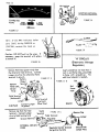
TIMING ADJUSTMENT. To change timing, loosen the d_stributor hold down
screw or bolt and rotate the distributor body as shown in Figures
36 and 37. until proper timing is indicated.
Test Number 17--TimingAdyanceSystems
NOTE: The following centrifugal and vacuum advance tests are general
ones and may not apply to many of.the more modern vehicles. Many of today's
vehicles have complex emission and ignition control systems which may alter
or prevent spark advance from taking place under various conditions. It
is therefore very important to consult your vehicle service manual for
the proper procedures to check and/or repair advance systems.
Ao
Mechanical
CENTRIFUGAL ADVANCE. With the distributor vacuum hose disconnected and
plugged, operate the engine at specified idle speed and note position
of timing mark. INCREASE engine RPM slowly and observe movement of timing
mark. The mark should move steadily and without jerking in the opposite
direction tO fly wheel rotation, up to approximately 1800 RPM. Decrease
speed and mark should return smoothly to its original position.
VACUUM ADVANCE TEST. Operate the engine at 1500 RPM and connect the vacuum
advance hose to the distributor vacuum control and observe movement of
the timing mark. The mark should move opposite to fly wheel rotation
and may appear beyond the range of the degree indicator with a normal
operating vacuum control.
_
Hold down
screw or bolt
BATTERY POST ADAPTER CONNECTIONS FOR STARTING ENGINE
FIGURE 37
ROTATION
FIGURE 34
..............................
' ...................
II1[I fl[
[[[[
[[[[I
I
J[lll
rr
i rrrlll
Vehicle
Battery
ROTATION'\II
1[Ii_"_
_/
Tester
PlckuI
FIGURE 35
..........
, .......................................................
11111111
Rotor
Rotation
hill
I[IH[
Rotor
Rotation
I1
ifll[i[lllll
SEEPAGES 6 AND
PROPER HOOK-UP
RPM
7 FOR
FOR
NO.I
SPARK
PLUG
Advance
Retard
Advance
FIGURE 38
FIGURE 36
rage _
RECONNECT FOR VACUUM
ADVANCE TEST
FIGURE 39
Bu
Electronic
Many of today's modern vehicles use sophisticated computer controlled
spark advance systems. Your Craftsman Analyzer, a top quality timing
light such as the Sears 213400 Timing Light or 219400 Advance Timing
Light, and the vehicle service manual are essentialitools for accurately
checking these complex advance systems.
IMPORTANT: DO NOT ATTEMPT TO SERVICE THESE ELECTRONIC ENGINE SYSTEMS
WITHOUT THE VEHICLE SERIVCE MANUAL.
Some of the Systems
Chrysler
Corporation
currently
in use are:
ELB (Electronic Lean Burn) introduced
in 1976, Re-named ESA (Electronic
Spark Advance) in 1979.
Ford Motor Company:
EEC I, EEC II, EEC 111, (Electronic
Engine Control) introduced in 1977.
General Motors:
ESS (Electronic Spark Selection)
introduced in 1977.
EST (Electronic
Spark Timing)
ESC (Electronic
Spark
Control)
C-4 (Computer Controlled Catalytic
Converter)
C-3 (Computer
Conmland Control)
Page 3Z
Test Number IB--Carburetor Adjustmentr-M_xture (Atr_Fue!_Ratia_
I.
Rotate the Function Selector Switch to the RPM position. Slide the
Range switch to the L0-1200 RPM position for idle speed tests.
2. EMISSION CONTROL SYSTEMS, Carburetors on late-model vehicles usually
have sealing caps on idle mixture screws which prohibit or restrict
carburetor adjustment. These are factory calibration seals. Refer
to vehicle manufacturer's service manual for mixture screw adjustment
procedures.
3. IDLE MIXTURE ADJUSTMENT. It is adviseable whenever possible to use
the mixture adjustment procedure as outlined in the manufacturer's
service manual. The following procedure should work well, however,
on those vehicles without emission control systems. Turn the idle
mixture screw in (lean) until the idle RPM starts to decrease and the
engine begins to idle roughly. When this point is reached slowly back
the idle mixture screw out (rich) until the maximum steady RPM is obtained.
When making any mixture adjustment only turn the mixture screw i/8
of a turn at a time. Between adjustments allow about 30 seconds for
the engine speed to stabilize.(Figuro 40)
4. MULTI-BARREL CARBURETORS, Repeat procedure described in Test Number
3 on EACH mixture screw until the smoothest maximum RPM is obtained.
Turn each screw i/8 of a turn at a time to prevent engine stalling.
If the final idle RPM is now higher than specified, readjust mixture
screws again until no further increase is possible.(Figure 4))
5. NOTE: On vehicles with emission control systems, air injection pumps
and positive crankcase ventilation, refer to vehicle tune-up decal in
the engine compartment for idle adjustment procedures.
IMPORTANT! Air/Fuel mixture adjustment is one of the more critical adjustments on the engine, Fuel economy and Emission Control can be diminished
through incorrect settings or adjustment, Carefully follow the vehicle
manufacturer's instructions when adjusting carburetor idle mixture.
TYPICAL,SINGLE
AND MULTIPLE BARREL
CARBURETORS
Curb Idle Speed
Idle
Adjustment
_ixture
Screws
Idle
Mixture
Screw
FIGURE 40
Anti-Dieseling
Solenoid
FIGURE 41
Pege 33
T_},t Number_!9--CarburetorAdjustment--Curb
2.
idle Speed
Rotate the Function Selector Switch to the RPM position. Slide the
Range Switch to the L0-1200 RPM position for idle speed tests.
IDLE SPEED ADJUSTMENT. Engine must be at normal operating temperature
before setting curb idle. Refer to vehicle specifications for idle
RPM range. Check for variations in curb idle with air conditioner on,
and any other specified idle range requirements.
Curb idle speed can be affected by other engine adjustments such as
timing, air/fuel ratio, and emission control operation. Carefully follow
manufacturer's instructions when adjusting curb Idle. Be certain to
recheck it after making any other engine adjustments.
Aw
8_
Anti-Dleseling Solenoid Adjustment
The purpose of this device is to prevent engine run-on (dieseling) after
the key is turned off. Basic operation of this solenoid is as follows:
When the ignition key is in the run position, voltage is applied to the
solenoid, energizing it and causing it to move the idle position of
the throttle. Curb Idle is adjusted with the solenoid energized. When
the key is turned off the solenoid retracts and allows the throttleplates to close or return to a base idle, hence, sh_tting off the fuelialr
supply to the engine. By using the RPM, VOLTS, and OHMMETER sections
of your Craftsman Analyzer and specific tests described in your vehicle
service manual, you will be able to diagnose faults and properly adjust
the antl-dleseling solenoid.
Air-Conditionlng Solenoid Adjustment
The purpose of the Air Conditioning solenoid is to maintain proper engine
idle speed with the vehicle's air conditioner running. It is
energized by the same circuit as the Air-Conditioning clutch and
when energized "kicks" the throttle enough to bring the idle to
its intended curb idle speed, By using the RPM, VOLTS, and OHMMETER
sections of your Craftsman Analyzer and specific tests described in
your vehicle service manual, you will be able to diagnose faults
and properly adjust the air-conditioning solenoid.
Page 34
Test Number 21 and 22-_Fast !dle and Automatic Choke Adjustment
The purpose of the fast idle function is to maintain proper engine
speed during cold engine and warm-up operation. Additional throttle
opening is needed with the automatic choke butterfly valve in a closed
or partially closed position to keep the engine running smoothly and
prevent stalling. The choking action provides a richer fuel-air mixture
during cold engine operation to compensate for poor fuel_atomization. The
increased idle speed warms up the engine quickly which enhances fuel-air
atomization and mixing.
The fast idle adjustment screw seats on a cam which is thermostatically
controlled through the choke linkage. As the engine warms, the choke opens,
the fast Idle cam drops to progressively lower steps and the fast idle
speed gradually approaches curb-idle. On a fully-warmed engine, the fast
idle cam releases the fast idle adjustment screw completely. Engine
Idle speed is then controlled by the curb idle adjustment screw.
Fast idle adjustment procedures differ among the various automobiles.
Consult your specific vehicle service manual for proper procedures. It
may be necessary to bypass one or more spark timing or emissions system
controls, either vacuum or electric, while adjusting the fast idle.
Many late model vehicles use a full electric or an electrically
assisted choke. It contains a small electric heater which activates a
bimetallic coil spring or belleviile washer to reduce the choke time
under certain conditions. This heater may be controlled by a temperature
switch located either in the choke housing or elsewhereion the engine.
The Ohmmeter Function can be used to confirm switch continuity, heater
element resistance and related wiring. The Voltmeter function is used to
confirm the presence of voltage to and within the choke system as directed
by your vehicle service manual. Use the RPM function to set fast Idle
per manufacturer's instructions.
D=._ 35
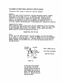
Test Number 23--Ignition Coil
Refer to Test Number 9--OhmsTest
(sections I-7) for Ohmmeter use.
IGNITION COIL PRIMARY RESISTANCE TEST
I.
2.
3.
4.
Set the Range Slide Switch to the OHMS X I position.
Remove the primary wires from both coil terminals.
Connect the RED and BLACK test leads to primary coil terminals, as
illustrated in Figure 42.
Observe reading on the Low Ohms scale, then re-connect primary wires.
BLACK
FIGURE 42
PRIMARY RESISTANCE
Ao
B4
TEST CONNECTIONS
The reading should meet the vehicle manufacturer's specifications
Generally, the coil primary winding resistance should be between I and
2 ohms. Check your vehicle service manual for the exact value.
if the reading is substantially above or below the manufacturer's
specifications, the ignition coil is defective and should be replaced.
COILSECONDARY
RESISTANCE
ONOHMSX 1000 POSITION
FIGURE43
I.
2,
3.
Remove the high tension lead from the coil tower, Be sure the ignition
switch is OFF.
Connect one of the OHMMETER test leads to either coil screw terminal.
(On late model Ford cars, use the Ford Adapter as illustrated on page 25.)
Connect the other lead to a spark plug adapter and insert in the coil
tower as shown,
Read the Ohms X 1000 scale on the meter and compare the reading with
the manufacturer's specification in the next column.
TEST RESULTS
The resistance of most coils for standard ignition systems are given in
the table below,
_NUFACTUREB
SECONDARY RES!STA_4CE_
(OHM_S)
American Motors
6,500 to 9,500
Chrysler
g,Bo0 to 11,500
Ford
7,500 to 9,000
G. M. Delco Remy
5,500 to g,500
If the reading is higher or lower than the manufacturer's specification,
the coil should be replaced.
rdge Jl
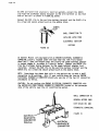
Test Number 24--Ignition
Cables
Refer to Test Number 9--OhmsTest
(sections 1-7) for Ohmmeter use.
IGNITION CABLE TEST
Standard ignition cable is NOT solid wire. It is a graphite impregnated
fibre conductor with a built-in resistance of 1000 to 50,000 ohms,
depending upon the length of the cable and the type of _ngine. This
resistance is necessary to suppress spark interference with radio,
television, and other communication reception. It also contributes to
longer distributor cap and spark plug electrode life. If the resistance
value of the cable is significantly increased by stretching or breaking the
internal graphite impregnated conductor, the engine will misfire and its
overall performance will deteriorate.
I.
2.
3.
4.
5.
Remove the cables from the engine. When removing the wire from the
spark plug, grasp the spark plug boot and twist and pull wire
with a firm, steady force. DO NOT yank on the cable to remove it.
Use the X 1000 position on the RANGE SELECTOR of the Craftsman
Analyzer.
Connect the RED and BLACK Ohn=netertest leads to the ends of the cable
as shown below, and use an adaptor spring at the SPARK PLUG END of the
cable as shown.(Figure 44_
Gently flex the ignition cable while testing, if the OHMMETER reading
wanders excessively or rises to infinity (,o) thelcable is defective
and should be replaced.
Consult your vehicle service manual for the proper resistance range
per inch or foot of cable. Replace those wires which are out of
tolerance.
ADAPTER SPRING,
DISTRIBUTOR END
BLACK
SPARK PLUG
END
IGNITION CABLE
TEST CONNECTIONS
FIGURE 44
'RED
Page38
Te__..t.Numbe.r....
2 5._.Ba.]]. ast, ..Res.!sto r
Refer to Test Number 9--Ohms Test (sections 1-7) for Ohmmeter use.
The purpose of the ballast resistor (when equipped) is to limit the
current available to the ignition coil when the vehicle is running.
Failure of this resistor results in a dead engine. If the engine trys to
start when cranking, but the instant you release the key,it stops, then
you may have an "open" ballast resistor. You can feel and hear the engine
cranking speed increase because the ignition system is trying to take over.
With the ignition key off, locate the ballast resistor and remove the
wires that are connected to it. (The ballast resistor is usually a
white ceramic block with brass terminals and is generally located on the
fire wall. If you have difficulty locating it, consult your vehicle service
manual.)
NOTE: Many Chrysler Corporation Electronic Ignition systems use a dual
ballast resistor, One side of this resistor functions exactly as indicated
above. The other side is the auxiliary ballast resistor and it should read
approximately 5 ohms.(Figure 45)
PROCEDURE
The OHMS scale is used to test the ballast resistor. To test the ballast
resistor, disconnect all leads at their terminals to pr@vent possible damage
to the analyzer or to prevent inadverdent measurement of other circuits
connected to it.
CONNECTIONS:
Ii
2.
Insert the white plug OHMS lead into the corresponding tester socket,
Connect the RED and BLACK clips to the ballast resistor as shown. Some
ballast resistors are dual units--such as on some Chrysler automobiles,
while others are single units--or resistor wires. Some ignition
systems utilize the ballast resistor in the coil primary (see ignition coil
test).
TEST PROCEDURE:
i.
2.
3.
The Ohmmeter will read full scale at the extreme right hand side,
INFINITY ( Oo ), with the BLACK and RED clips disconnected.
When the clips are connected together, the meter pointer will
read zero on the left (short circuit or zero ohms).
To measure the ballast resistor, connect the RED and BLACK clips as
shown in Fi_ure 45 . Set the Function Selector Switch to the OHMS
position.
Set the Range Selector Switch to the LOW scale. Typical readings should
be between 0.5 and 7.5 ohms.
IMPORTANT: Consult your vehicle service manual for the exact OHMS value
for your car. The value read should be very close to the specified value
as large differences can cause damaged points or electronic ignition module
(when too low).
Hage ._J
4.
If the meter reads _
, (right hand side of the scale) the
ballast resistor is open and must be replaced.
CHRYSLER
_,REGULAR
BALLAST -.5 TO .6
,_ OHMS
BLACK
OHMS
"--I
BALLAST RESISTOR TEST CONNECTIONS
FIGURE 45
Test Number 26--lqnition Switch
The ignition switch performs many duties beyond starting the vehicle. With
the guidance of your vehicle service manual, your Craftsman Voltmeter and/or
Ohmmeter can confirm operation of the ignition switch,
Some of the ignition switch functions are as follows:
i.
2.
3,
4.
5.
Activate starter relay (start position)
Bypass ignition ballast resistor (start position)
Confirm tell-tale cluster lights (start position)
Activate ignition
Activate accessories
If you have difficulty with any of the above circuits,
is a possible source of trouble.
Consult your vehicle
exact diagnostic procedures.
the ignition switch
service manual for
Page 40
ELECTRONIC IGNITION SYSTEMS
The following ten pages are devoted to the four basic Electronic Ignition
Systems as used by American Motors, Chrysler Corporation, Ford Motor Company,
and General Motors,
The diagrams and charts will step you through point-to-point testing of the
various components within each system. You will use the VOLTS, OHMS and
POINTS-LOW VOLTS positions of your analyzer. It would be advlseable before
beginning these tests to review the use of the VOLTS, OHMS, and POINTS
positions of your analyzer as shown earlier in this manual.
American Motors 1975-76
American Motors 1977 & Up See Ford Motor Co.
Chrysler Corporation
Ford Motor Company
General Motors (integral Coil)
General Motors (External Coil)
Test Number 27--Amerlcan Motors Electronic igni_tl.pn..._.Sys.tem
Te.st_
Number 28--Chrysler Electronic Ignition System
Test Number 2g--Ford Electronic igD_ItlonSy_s.tem
Test Number 30--Delco HEI ignition
Test.Number 31--DelcQHE(..Ign!.t!on_.System_H!.tbSeparate
Coil
Page 41
GENERAL
MOTORS
When performing
High Energy
HIGH
Charging
Ignition
ENERGY
IGNITION--
DISABLING
System teals on General
(HEt),
Motors
the engine can be prevented
........
SYSTEMS WITH COIL IN DISTRIBUTOR
i II .,r
r, ,,
PROCEDURES
vehicles
equipped
from starling
,
.,,i,rbl Ir I,
with
as follows:
, ,, J,im.,.I,,,, ,,,, ,,,,,,,,,
CAP
Disconnect primary wire from the BAT
terminal on the distributor cap,
_r
_'_--_ ' _,_"€_,.
CAUTION: The tachometer terminal must
NEVER be connected to ground at the
distributor cap, as damage to the
distributor module can result.
SYSTEMS WITH SEPARATE COIL
Remove high,tension coll wire from colt
secondary terminal, Connect Jumper Wire
between coil secondary terminal and a
good ground on the engine.
.......................................................
LI]_
IL
IILILI[_II
LJLI
l ..........
_I
I
IILIIIIIILIi
.........................................................
HEI WITH ELECTRICAL
DIAGNOSTIC CONNECTOR
Insert the GM Diagnostic Connector
Terminal in terminal No, 6 of Electrical
Diagnostic Connector, Connect jumper wire
between this terminal and a good ground,
CAUTION: The tachometer terminal must
NEVER be conneoted to ground at the
distributor cap, as damage to the
distributor module can result.
JUMPER'
WIRE
L
DIAGNOSTIC
CONNECTOR
ELECTRICAL
DIAGNOSTIC
CONNECTOR
TERMINAL
G
ENGINE
GROUND
PRIMARY
Page 42
,Tes_t
Number 27
ELECTRONIC
MODt LE
HIGH TENSION
ITPUT TERMINAL
POS,-,,_
COIL
TERMINAL
COIL
TERMINAL
GROUND
IGNITION
SWITCH
BLACK
COIL
NEG4
POS
12 VOLT
BATTERY
DISTRIBUTOR
CONNECTOR
DISTRIBUTOR
DISTRIBUTOR
SENSOR UNIT
GROUND
FIGURE 46
AMERICAN
MOTORS
ELECTRONIC
IGNITION
SYSTEM
Page 43
Number
27 Continued
AMERICAN
MOTORS
ELECTRONIC
IGNITION
COMPONENTS
_,s ¸ - =±-
S[LECTOR
KNOB
TESt
C LIP
CONNECTIONS
POSITION
RED
j
, ,,111 ..........................
firST
BLACK
:........................................
PROCEDURE
AND
RESULTS
J
2
A
Battery State
of Charge
16 VOLTS
1
Batte,y
Pos.(+)
Neg.(-)
3
Coil
B fgnltio_
Switch
16 VOLTS
Remove Coil High Tension W_re from the distributor and
ground _t. Crank Engine. Meter should read above 9.0
Battery
Poi,(*)
!
4
Call
and Electronic
Module
...................................
:
16 VOLTS
Wffh Ignition Switch on, meter should read _t least |0
vain,
tf not_ inspect the sw_tch fm lame connections
Neg,(_)
and faulty €onfiders,
I
Unplug dlstHbutot
flattery
Ne0.(-) Neg. (-)
Terminal
_ .-o= ...........................
OHMS
D Colt Pdmory
Reslst_nce
X [
. ...............
OHMS
x IOO0
Coll
Pro, (÷)
Terminal
Coil
P_. (÷)
Terminal
F Distt{butor Semor
OHMS
x |
Unit ContinuHy
8
DistHbuta¢
Connector
Cavity
OHMS
G Distributor Set_,_or x 1000
U_It to Grou_',d
Replace switch ifdefective,
connector.
With
Ignition
Switch on,
meter should read between 5 o_d 8 volts,
If OK proceed
tO Test F, if less thor_ 5 Volt: or more than 8 vohst proceed wt_ ?elf O,
= :
3
3
E Coil Secondary
Retlstdnce
Replace
flattery
....Termlnal
C Call Primo_y
rafts,
If not_ charge battery and repeat test.
H|gh Tension Wire lt_ dlstr_butor.
i
l|ottery
Neg. (-)
4
Coil
Neg. (-)
Terminal
5
WIth distributor connector unplugged and call negotlve
lead dIsconnected,
meter should read between .7and
2.5 €;_ms with Ign;t;o_ Switch ofF. if not, _eploce €o;t,
With ign_Hon Switch
off, and negative
(-) call
lead dis-
Coil hlgh
tension
connected, connect RED Clip tO positive (÷) Ct>;I ferminal_
and hold BLACK cllp in coil h_gh ten_ion output terminal.
output
Teetotal
Meter should read betwqlren B,000 and 16,000
not,, repJoce €oli.
ohms.
if
9
Distributor
Co..ecto_
Pin
Meter should read between ,8 and 3.0 ohms. if not, replace Di:trlbuto_ Se_s_ Uait.
9
Oisttlbuto¢
Cermet tot
Pin
If tests above do not locate defective components,
is not serv{ceob|e, _t must be replaced.
Meter should not move.
Sensor Unit.
then the trouble
ff it does, replace
is wlth the Electro, to Control
Distrlbuto_
Unit.
Since this unit
Page 44
POS
IGNITION
SWITCH
NEG
I2 V, BATTERY
GROUND
COMP.
SIDE
RESISTOR
NOTE LOCATION
:H
DUAL
BALL._ST
AUXI LIARY
RESISTOR SIDE
ELECTRONIC
CONTROL UNIT
COIL
FIGURE
ISTRIB!.
CONNECTOR
CHRYSLER
ELECTRONIC
DISTRIBUTOR
IGNITION
SYSTEM
47
CHRYSLER
ELECTRONIC
IGNITION
COMPONENTS
I
SELECTOR
KNOB
TEST
PQS_TION
A
B
Battery StcJ_'e
of Charge
Compensofing
51de of Baflatt
C Col! Primary
and Electroni€
Control Unit
16 VOLTS
t6 VOLTS
POINTS
See
Note f 1
OHMS
xl
D Coil Primary
CLIP
CONNECTIONS
R{O
J
BLACK
Co_tinuity
P_.(*)
Neg.(_)
pcoceed tO Test B.
I
Coil
PUS.
Terminat
Buttery
Nee, (-)
O Balt_t
X i
1
Ektttery
Nee, (-)
5
6
Colt
POS,
Coil
NEG.
Terminal
12
Call
Auxiliary
X 1
Side
H Pick-up Call
to Ground
OHMS
1000
With Ignlttom Switch
off,
meter
ohms. If it duel riot, replace
proceed tO E, '_
If test OK_ repface
Elec-
_hould read one to three
Ignition
Coll,
teod from call tower.
If OK,
Connect
BLACK e,ltp to t_er contact,
With Igmition off, meter
sl_JId read 5,000 to 25_000 ohms. l| it does not, re-
Contact
place
coil,
io ........................
.mov.
oths.p
.on.......................
,ram
.......................
Bo.os,
..........
wo°
.........
th:
,.psl
.......
9
Ballast
Term lno I
(C_p,Side)
4
Batiast
Terminal
(Aux..Side)
englne not rumntng, meter
1,8 volts,
if less than 0.3
Test K_
Remove hlgh teri, to_
Cull
To_er
or con-
p_oceed with T_st O.
IF OK, proceed wlth Test F. if
h|gher tha_ 1,8_lnspe_:t wffes a_d connection at Elecffonic
Control Unlt,
if wlres und contractions OK of Electroni€
Control Unit, perform
trori_ COntrOl Unit.
BaUost
Term _naI
7.5 volts, proceed to Test C,
should feud of lent 9. If
W_th Ignition Switch on and
should read between 0.3 and
6
Call
NEG,
Termir_l
(Camp. S;de)
OHMS
Rei;stanCe
proceed to Test E. tf above
If OK_ crank ettgtne,-Vohage
not_ It_ct
igntt;o_ Sw;tch for bad con_ecttons
tach.
Replace high tension wlre.
j,i,
OHMS
With ignlfion Switch on and engine not ruHnlng, meter
should read 3,5 to 7,5 v,oltt,
If le_s than 3.5 or xero
5
POS,
TermIrtoJ
Baltost
Rot;trance
Camp. Side
RESULTS
RemQve the High Tet_slor_ Wire from the dls.ttibutor and
grouttd it. Crank Engine,
The meter should read at iea_t
9 ruffs while cranking.
If les_, cNarge the buttery and
..............................................................................
F
AND
?
8ah'et-y
OHMS
x i000
PROCEOURE
2
Battery
Termini
E Colt Secondary
TEST
3
8
1
read 0,2
if it does _Ot, replace Ba!lc_st.
t_ 1.5 ohms.
Termir_t_
from Ballast a.d
(-)
with
clips ©orinected to teemlr_ls 4 and 3 on Ballast, meter
should read between 3 to 7 ohms, If It daes not, replace Ballolt_ reconnect Slip-on Termlrm!_ at Ballast.
Disconnect dlstttbuto_ conriecto_.
Battery
Neg.
9 and t0 on Ba!last_ meter _hauld
Remove both Slip-on
Ba!last
Termlnal
(Aux_Side)
O;stributor
Connecto_
cot_t_ected to Terminoh
movement,
to Test J,
Metes should show no
If It do_s, replace Pick-up
Cot1.
Proceed
Pin
J
Pick-up
Coil
OHMS
x !000
Contlnu;ty
7
Distributor
ConneCtor
i3
Distributor
C_ffectot
Cavity
K
11
Electronic
Control
Unlt
POINTS
Ground
See
Note # 1
Note fl
Pin
- Use GREEN end BLACK
1
Electronic
Battery
Control
U.It Case
Nee.(-)
Disconneet
D|ttrtbutor
Connector.
Wi_
RED €lip con'.
netted tO Distributor Connector Cavity and BLACK cllp
€onnected to Dis_lbutor Cannect_t P;_, meter should
toad belween 150 and 900 ohms. Proceed to Tett K.
Scrape block paint off small sect;on of Electronic Control
Unit.
With key an, ta_ch GREEN IclIp to metal surface.
Meter should read tess them 0.25 volt.
If it reads higher,
turn off lgmitton Swltch,
remove Electroni€
Control
Unlf
from Car mounting surface, and _leen surface and Electronic Coritrol Unit base of dirt or paint.
Remount and
retest.
[earls for this te_t only.
If tests above do not !acute defectIve componenfs_
is mot _rvlceable,
;t must be replaced,
then the trouble ;s with the Electronic
Contro_ U_t.
Since this unit
Page 4(_O1L CONNECTOR
TO "DEC" TERMINAL
(DISTRIBUTOR ELECTRONIC CONTROL
YELLOW
IGNITION
SWITCH
12 V.BATTERY
GROUND
D.E,C.
MODULE
TO "BAT"
TERMINAL
DISTRIBUTOR
GROUND
BLADES
SOCKETS
FIGURE 48
ORA I(
ORANGE
BLUE/
_OWN
BLACK
BLACK
FORD ELECTRONIC
IGNITION
SYSTEM
LE
* inspect Harne_s Connectors for
white & blue leod terminal as
1974_ 1975 and later models
Test Number 29 Continued
FORD
POSITION
A
Battery
B
RED
16 VOLTS
Battery
OHMS
x_
O Call Secot_dary
i0
4
9
Co{l
D[C
BAT,
Te_r_i_al
OHMS
4
x 1000
Coll
BAT,
Cat_finulty
Te_mlr_l
11
Carl
Tower
Termir_l
L_ ........................................
Voltage Dt_t_
ir_ Resist_t_ce
Battery
9
OHMS
x 1
C Coil Primary
Reslston_e
E
I
P_. (÷1 Neg,(_)
ResistanceWire
Contact
4
2
16 VOLTS
Coil
B_ttery
Wire
BAT.
Pos.(*)
3
F Power to
D_,C Module
COMPONENTS
16 VOLTS
TEST
AND
I BLACK
2
State
of Charge
IGNITION
CLIP
CONNECTIONS
SELECTOR
KNOB
T{ST
ELECTRONIC
1
Whhe/Blue
Lead
Term;hal
flattery
Neg. (-)
PROCEDURE
RESULTS
Remove Call High Tensiot_ Wire from the dlstr_butor and
ground it. Crank E_gtne,
Meter should read at least
9 volts,
If less, charge battery and proceed.
High Tet'_ion Wire,
Replace
With Igttlttan Swttch OFF,, meter should read 1 to 2 ohms.
If reading is hlgher_ replace teslstance wire.
With ignitior_ Switch
If it does not,
with Test D,
Remove call
off, meter should iead
replace
ignttiot_ Coil,
high tension lead From coil
i to 3 ohms,
1f OK,
proceed
rowe,.,., C0nne_t
BLACK ¢llp to inner €omact.
With _g_itfo_ Switch off,
mete_ should read 5,000 tO 25_000 ohms, !I it does not,
replace
coil,
With Ignitlot_ Switch or_, meter should read 5 to ? volts.
if higher thot_ 7 votts_ recheck Test B, If Iowe% proceed
with Tests F _r_d O.
Seporote the Fk_mess Connector €ontaining Whlte/Blue
Wife from DEC Module, and connect RED cllp to Whltei
Blue Female L_d
Terminal.
With Ignition
Switch on,
meter should read !0 to 1_ vOItt.
If low or zero, _xtrform voltage drop test on lgmtlo¢_ Switch Retiit_nce Wtre_
Test E, It OK, replace Ignltlo_ Switch.
6
O
OHMS
x 1000
Pick*up Coll
to Ground
O_or_ge
Distributor
Pick -up
Conr_eeto_
Terminal
6
Oronge
H
OHMS
Pick-up Call
Con tl M_Jity
x IOn0
1
Batter y
Neg, (-)
Note
N_dule
POINTS
Distributor
Pick -up
Connector
Pi_k-up
Connecto¢
Grou_
See
Note # 1
11 - USe GREEN md
BLACK
le_s
8
DEC
Module
Case
should not move,
full scale reading_ replace
If there is movemet_t or o
Pick-up
Call Assembly.
7
Purple
Distributor
Terminal
j
Meter
Meter shouldre_d between 400 arid 800 ohms. if it reads
higher or Iowe_ replace Pick-up Coil Assembly.
Terminal
1
8_ttery
Neg. -
With Ignitlot_
Switch
on÷ momentarily
touch
GREEN cllp
to DEC Module Housing.
If meter reads more than
0.25 volt_ remove Module from mounting,
¢1_
_u_[a_:es, remount securely and retest.
for this test €_ly,
if tests €_bove do t_ot locate defective compo_ent_
is not servi{:eoble_
it mu_t be replaced,
then the trOuble
is with the Electronic
Co_ttot
Unlt.
Sit_ce this unlt
Page 48
Test
Number
30
DISTRIBUTOR
PINK
CAP
LEAD
IGNITION
SWITCH
HiGH TENSION
OUTPUT
POS.
CONDENSER IS USED ONLY
FOR RADIO INTERFERENCE
SUPRESSION AND NOT AT
ALL INVOLVED
IN IGNITIOI"
PERFORMANCE.
NEG.
12 V BATTERY
BROWN
GROUND
/
LOWER HOUSING
HARNESS
"WHITE
EN
DISTRIBUTOR WiTH CAP
AND ROTOR REMOVED.
DELCO HEI IGNITION
SYSTEM
WITH
FIGURE 49
ELECTRONIC
MODULE
COIL IN DISTRIBUTOR
CAP
-PiCK-UP
LEADS
• _w.
_S!: Number
DELCO
_3Q,,Continued
HEI IGNITION
COMPONENTS-SYSTEMS
WITH COIL IN DISTRIBUTOR
CAP
S LECTC
.................
............TESTPROCEOURE
TEST
A flattery State
of Charge
KNOll
16 VOLTS
CONNECTIONS
2
J_ttery
Pro,(÷)
t
Battery
Neg. (-)
.
4
B lgnttton
Swffch
16 VOLTS
C Coil Prlmory
Reslst_nce
OHMS
x I
D Coil
Secondary
lleil:_n_e
E CallPrlmary
Ca_ttnulty
F P,_werto
Ele_tronlc
Package
OHMS
x lOCK)
Olst.Cap
Pink Lead
3
OtiS,Ca"G."T ere,P
I1
High
16 VOLTS
3
Dl_t.Cap
"_-"Term,
S
"B+"
Term,at
Dlst,Cop
9
G Lower Housing
Harness
16 VOLTS
......................................................................................................
t
fiettety
Nag.(-)
1
Battery
Nee, (*)
Module
10
H Lower Ho_lng
Hameu
Continuity
16 VO LIS
oL_s
J
Pick-up Coil
Continuity
K Pick,.u_ Call
to Ground
x 1000
OHMS
x IOgO
Term,on
Module
l
II_ttety
Nag.(-)
7
White
Pick-up
Lead
6
Green
Ptck=up
Lead
?
White
Pick.,up
Lead
I
Battery.
Neg,(-)
If tests ==bore do not Io¢ote defective
isnot lervlceoble,
itmu_t be replaced.
components,
¢.. ..................
if ice, _eplace
Remove Cap and Rote% and dhcon,e_t LowerHouth_g
Haree,s. Meter should read behveen 0.2 and 0.? ohms,
If meter doesnot read, replace Ignition Call located
in Distributor Cop.
DIIt.Cap
Grid. Term
1
Battery
Nag.(-)
"B"
_'erm,on
Conttnully
ihoutd read 10 rafts or t_igher,
Ignltlon Switch circuit.
8
BAT,
Terr_,ot
Dht,Cap
l
Battery
Nag,(=)
,. ............
Cgnne_:t REDclipto Pink Legd from Olstrlbutor Cap,
With Igr_itlo_ Switch m'_end engine nat running, meter
12
Ten_lon
Output
Terminol
t6 VOLTS
.
Remove Pink Lead 4 from Dhtrlbutot Cop end crank
e_gtne, Meter should_ead at least9,6 vghs.lf lawe_,
_herge tmtt_y a.d retest.
With Ignition Switch off÷ meter reads test than IO,O00 or
more than 30_000 ohms, replace the ignition Coil
Assembly.
Rec_nect PI_ Le_d 4. lie s_xe st.mrthree hod Lower
Houd_g Horm_l tt dh_onnected
_rom Olsttlbutor Cap.
tarmacs REDclip to "C-_' term;_l,
With Ignltlm
Switch on, meter shouldread at loess IO veiN.
With REDclip connected to "B÷" Termir_l end ignition
Swltch on, meter shou_ldreed at leatt 10 volts. If lower
or =ere, recheck Test_. If *.till
low, e_amlne termlnoh
and conne¢.'tlonsInside Distributor Cop Cover.
Rec_nect _r** I,od Lower Hou_tngHornes_€onnects.
With Ignition Switch on, meter sh_ld rood Ot least 10
volt_l, If low or z',ero, repair or replace three te_l
"Lower Hauslr_gHornets."
Connect REDcllp to Module "C-" terminal. With
ignition Switch _, meter should read at I_st i0 volts.
If low or zero, repair or replace three le_td
"Lower Houttng Harness."
Ditconnect Green and White Pick-up Llmds from Electronic
t_Jute er_ connect to RED=endBLACK ¢llp_. Meter lheald
read between 550 and 1,_lO ohms. If It d_tt nat, tapioca
Pick-up Call Alsembly.
Connect RED clip to white Pick-up Lead, lie certain
GREEN L_d Is clear from oil metal to'facet,
h_lter
thould not move, tf it does, replace Pick*up Coil
A,embly,
then the trouble
is wlfh the Electronic
Control
Unit,
Since this unlt
-t,_
Page 50
Test Number 31
IGNITION
SWITCH
IGNITION
SWITCH
FEED TERMINAL
POS.
COiL
CONNECTOR
NEG
'HIGH
OUTPUT
TENSION
TERMINAL
L
HOUSING
HARNESS
GROUND
CONDENSER iS USED ONLY
FOR RADIO INTERFERENCE
SUPRESSiON AND NOT AT
ALL INVOD/ED IN IGNITION
PERFORMANCE.
FIGURE 50
DELCO HEI IGNITION
SYSTEM
WiTH
SEPARATE
COIL
Test Number 31 Continued
DELCO
rage
HEi IGNITION
COMPONENTS-SYSTEMS
WITH
SEPARATE COIL
................
TEST
SELEC TaR
KNOB
CLIP
PROCEDUR_
TEST
CONNECTIONS
AND
RESULTS
POSITION
RED
Battery
State of
A
l_ttery
Pm.(_)
Charge
4
16 VOLTS
Ignition
Feed_re
C
Call
P_;_ary
Resist'a_ce
D
Call Secondary
Resistance
BLACK
|
Remove coil cover and Igt_ttlo_ Wire No, 4, Connect
REO clip to Ignition Switch Feed Termlrml. With
tgnit_on Switch on, meter should read at least I0 volts.
If low or z_o, replace tgnttlon Switch
circuit.
5
6
Coil
Terminal
Lowe_ Ha_ing
16 VOLTS
Remove Colt Con_ect;on_
tri_,l
l
Battery
Neg.(-)
11
t6 VO LTS
on
Module
Continuity
G
Pick-up
Coil
OHMS
x I000
Reslsl_nce
H
Pick-up Coil
to Ground
Terminal
OHMS
x 1000
to Ig_i-
Remove disl_'Ibuto¢ cap and rotor,
Reconnect Colt Con-
necta¢ and Ignition Feed Wire to Coil,
With Ign;tion
Swffch on_ meter should re_d at ieatt |0 volts, tf
lower, repair at replace i_wer Housing Ha_e.,
I
1
Green
Pick-up
Le_d
Pick-up
Lead
Pick-up
Lead
RED clip
slam Call Term;hal.
Meter shou4d read between 6,000
a_d 12,000 ohms, 'If not, replace ¢ot!.
Reconnect
High TensIon Wire,
Battery
Neg (-)
WEtte
e
Wl_lt,
and connect
I( lower,
Remove Coil High Tension Wire_ and connect RED clip
to High Tern;on O_ttput Te,'minol, BLACK clip to igni-
S
, Ignitlc_
Coil
Term;rot
Term;nall_
on
least 9.6 volts.
tion Coil Tevm;_l, and BLACK clip to Colt Terminat,
Meter should read between 0.2 and 0,7 ohms.
Module
F Lower Housing
H,ar net_ (grOwn)
from Coil and crank
l
Battery
Neg.(-)
_gMft;on
Coil
Term_rv_I
3
Hhjh
Tension
Swift_h Feed Terminal
engine.
Meter should read at
charge b_ttery and proceed,
x !
OHMS
x TO00
Remove Ignition
Battery
Neg,(-)
OHMS
Output
Terminal
Harness (Red)
Continuity
I
2
16 VOLTS
, 1..........
I
Ik_tlery
Neg, (-)
if test_ above do not lahore defective components,
it not servIceoble,
it mutt be repla_ed.
With
Ignit;o_
Swit¢_
volts,
It lower,
Homes| _
Disconnect
o_, meter
should
repoh" of replace
read at
least l0
Lower Housing
Green and W_lte Pick-up
Leads from Module
and connect to RED and BLACK cllp_,
Meter should
read between 500 and l,.SO0 ohms. If it does not, replace Pick-up
C_nect
Coil A.embty_
RED clip to White
Lead Is €iemr from 01i moist
Plck-up
move.
It' It _wt_, r_l_|oce Plck..u_
dlswibutor coo and €olor.
then the trouble
Lead.
sucre:m,
;s with the Electronic
Be certain
Green
/v_ter d_ould not
Coil A.embly.
Control Unit.
Reinstall
Since thIs u_it
b_
Page 52
Introduced in 1978 on a limited number of California mandated emissioncontrolled engines, the C-4 System is now standard equipment on most of
the Genera] Motors cars (except diesel and EFI). The main functlon_of the
C-4 System is to maintain the carburetor air-fuel ratio at 14.7 to 1.0--the
most efficient operating ratio for the catalytic converter. The electronic
carburetor receives a DWELL-TYPE voltage from the EleCtronic Control Module
(ECM) to maintain this air-fuel ratio under widely varying driving
conditions. The Craftsman Engine Analyzer can be used to check this
voltage by reading the six-cylinder DWELL scale, 0-60°, and by performing
the procedure in this section.
IMPORTANT--The C-4 System could be malfunctioning when any of the following
conditions are noticed:
The vehicle instrument panel "CHECK ENGINE" light illuminates.
Poor engine performance which includes=
1. Poor gas mileage
2. Lack of response to throttle
3. Hesitation, stalling, etc.
Complete C-4 System diagnostics, troubleshooting, and repair procedures
demand that you obtain the specific service manual f_r your vehicle and
engine combination.
CONNECTIONS:
On G.M. cars equipped with the C-4 System, a small, green, single-contact
DWELLMETER connector is normally provided to check the DWELL voltage to
the carburetor (usually located under the hood near the right front
fender wheel well, or near the carburetor, protruding from the wiring
harness). DO NOT ALLOW THE LEADS TO TOUCH GROUND OR HOSES--THE HOSES MAY
ALSO BE CONDUCTIVE.
Use the adapter pin as shown in the figure below. Connect the GREEN clip
from the Craftsman Engine Analyzer to the adapter pin. Connect the
BLACK clip to a clean and secure ground such as the engine block, and the
RED clip to the positive (+) battery terminal.
NOTE: The DWELLMETER should NOT cause a change in the engine operation
when connected to the vehicle's DWELLMETER connector. If there is reason
to suspect that a change did occur, recheck your connections.
TEST PROCEDURE
Position the FUNCTION SELECTOR switch on the Craftsman Engine Analyzer
in the DWELL position. All readings will be taken from the 6-cylinder
DWELL scale (0-60°), regardless of the number of engine cylinders in the
vehicle under test.
The following table is a typical C-4 System Performance Summary illustrating
the DWELLMETER readings under the given engine conditions.
Page 53
ENGINE CONDITION
I.
.
3_
4.
DWELLMETERREADINGS
Start Mode (cranking)
0o
Warm engine operation at idle
or part-throttle with constant
engine speed. See Note Below.
Constantly varying between
i0_ and 50_ (Higher engine
speeds result in faster
variations.)
Acceleration and deceleration
(changing engine speed)
Constantly varylng between
10_ and 50° (DWELL variations
may not be easily discernible
on the DWELLMETER during
rapid accelerations or decelerations but may be seen on
slower changes in engine RPM)
Wide open throttle (W. O. T.)
(under engine load--on the road
or with dynamometer).
Approx. 6°
NOTE: The input to the C-4 System which causes the Constantly varying
DWELL reading is an oxygen sensor mounted on the exhaust manifold
working through the ECM. This sensor must typically be above 6000 F
to operate properly. Engine cooling, restart, or excessive idling could
cause the sensor to go below 600°F in which case the DWELLMETER reading
will be some FIXED value between I0° and 50°. This syst@m may require
three to four minutes to reach temperature after a restart or cool-down to
resume the VARYING-DWELL operational mode.
ADAYTOR
PLUG
CONNECTOR
FIGURE 51
Used to provide Dwell Connection on G.M. C-4 Systems.
Test Number 33--Ground Strap!est(EnginetoBodyJ
The ground strap from the vehicle body to the engine provides the
return circuit from the lights and other accessories to the battery.
A
defective ground strap or ground connections could cause an inaccurate
voltage regulator setting, resulting in higher voltages to the electrical
system.
The ground strap can be tested as follows:
Page 54
I.
2.
3.
4.
B.
Insert the BLACK test lead p]ug into the BLACK "OTHER TESTS,'socket.
Connect the BLACK clip to a clean connection on the engine block and
the GREEN cllp to a clean connection on the car body. Scrape away
grease or paint, if necessary, to make a good metal-to-metal connection.
Rotate Selector Switch to the POINTS LO VOLTS position.
Start engine and operate at approximately 1200 RPM.
Turn on headlights and note reading on the 0-3.2 Volt scale.
GOOD--A reading less than .i volt indicates a good ground strap and connections.
HIGH--A reading exceeding .I volt indicates a defective ground strap or
its connections. Clean the ground strap connections and repeat
test before replacing ground strap.
GREEN
BLACK
REDCLiP
USED
•tD
G OOD"I-"_E
-'_"
"L5
PJZ3 2
HIGH
GROUND
STRAP
TEST
(ENGINE
FIGURE 52
TO
BODY)
vage
Test Number 34A--Puse Tests
Automotive fuses can be tested as follows:
Connect the BLACK clip from the analyzer's voltmeter lead to a good ground
on the engine or car body. Turn the Function Selector Switch to the VOLTS
position. Insert the BLACK plug into the BLACK OTHER TESTS socket. T_rn
the ignition switch to the ACC. position and turn on the accessory associated
with the fuse that is to be tested. Then touch both sides of the fuse with
the RED clip. If the meter indicates battery voltage on.both sides of the
fuse, the fuse is good. If it indicates battery voltage on one side and
nothing on the other, the fuse is open. If there is no reading on either
side, there is an open circuit between the fuse and the battery
On General
RED
blockss
Motors
insert a small
cars equipped
with "Autofuse"
nail _ bare wlre in the RED
clip as shown and use it as a test probe.
BLACK
FUSE TEST CONNECTIONS
_REEN CLiP NOT
FIBURE 53
_
Paqe 56
Test Number 34B--Horn
Set the Function Selector Switch to the VOLTS position,
Using the ALL OTHER TESTS leads, connect RED lead to the terminal
of the horn relay that connects to the horns and BLACK lead to a
good ground as shown in Figure 57. (Reverse leads for a positive
ground system).
I,
2.
MORN
HORN AND RELAY
CIRCUIT CONNECTIONS
HORN
RELAY
BLACK
TEST RESULTS
FIGURE 54
6
$
10
r
/
ZERO
I,
2.
3.
READING
Defective horn relay
Defective horn rlng
A break in wtr|ng be*,
tween the horn ring
and relay
READING LESS
THAN i0 VOLTS
1.
2.
Defective
Defective
horn
wires
3.
Relay points not
making good
contact
GOOD
Horn
operating
range
%
BATTERY VOLTAGE
READING
1.
2.
Open circuit in horn
Break in wiring between relay and horn
Page
Test Number 34C--Low Volt.ageIJropTests
in addition to the POINT RESISTANCE test described on page 20, this
position can be used to test the vehicle's electrical system for low
voltage drops. Set the Function Selector Knob to the POINTS LOW VOLTS
position.
Insert the BLACK plug into the BLACK OTHER TESTS socket. Read test results
on the 0-3.2 Volt scale. Each division on this scale is .I volt. This
scale has internal protection to prevent damage if the leads are accidentally
connected across full battery vol.tage. Use the GREEN and BLACK clips to
make the tests. The RED clip is not used.
Corroded or loose connections and frayed or broken cables can cause excessive
voltage drops in the starting circuit which can cause hard startlng, To
test for these conditions, connect the clips between I and 2, 2 and 3, 4
and 5, 5 and 6, 6 and 7, 7 and B, with the starter turning, Be sure the
high voltage lead is disconnected from the coll so the engine won't start.
During this test, no reading should be higher than .2 volts. If a reading
higher than .2 volts is observed during any of these tests, check the
cable or connections involved, clean and tighten the connections and
replace the cables or solenoid when necessary. If the meter reads to the
left of zero during any of the above tests, reverse the pos(tlon of the
clips.
®
®
STARTE R
BATTERY
VOLTAGE
LOSS TEST
CONNECTIONS
FIGURE 5S
Page 5B
With the increased sophistication of today's emission control systems,
many more solenoids are used than ever before. Air injection, EGR Action,
and throttle positioning are a few examples of the usage of solenoids.
Basically a solenoid converts an electrical signal into mechanical
movement. Hence they can be used to move valves or repositlon the
throttle. Since they are electrlcally operated, your Craftsman
Voltmeter and Ohmmeter can be used in conjunction with your vehlcle service
manual to confirm their proper operation. The service manual will tell
when voltage should be present at the solenoid and thevalue to activate
it. The Ohmmeter can check whether or not the coil in the solenoid is open
or shorted. Follow your vehicle service manual's instructions in all cases.
The OHMS scale is used to test the various lamps in the vehicle (headlamps,
parking lamps, convenience lamps, etc.) To test the lamps, remove the
lamp from the socket or otherwise disconnect from the circuit to prevent
possible damage to the analyzer.
CONNECTIONS:
i.
3.
4,
5.
Insert the white plug OHMS lead into the corresponding tester socket,
Connect the RED and BLACK clips to the lamp under test. Some lamps
have two filaments and each must be tested separately.
Set the Function Selector switch to the OHMS position.
Set the Range Selector Switch to the LOW scale. The cold filament
resistance will read very low--typically less than 10 OHMS.
If the meter reads oo , (extreme right hand side of the scale) the
filament is open-clrculted and the lamp must be replaced.
Test Number 34F--Motor Windings
The OHMS scale can be used to test the windings of many of the motors
used in today's vehicles such as the blower, wiper, headlamp doors, and
power window motors. Always make certain when testing the suspect motor
that it is completely disconnected from the vehicle. This will prevent
false readings as well as possible damage to the Analyzer.
With the guidance of your vehicle service manual you will be able to
'
diagnose an open winding, a shorted windlng,
or a winding shorted to the
motor frame. Your vehicle service manual will specify what resistance in
ohms should be present across the various motor leads. These values will
typically be low in value, hence the X i position of the Craftsman Analyzer
Range Selector should be used,
Page 5!
The Rear Window Defroster Grid can be checked quite easily with your
Craftsman Analyzer. You will use either the VOLTMETER, 0-16 VOLTS, or
the OHMMETER (X I) for performing these tests. Specific test procedures
are outlined in your vehicle service manual. Resistances encountered in
these circuits will be very low, typically less than one ohm.
CAUTION: Do not test across Grid Lines on the glass. _Although this
electrically conductive coating is baked onto the glass, it can be
scratched, causing an open circuit and rendering all or part of the heated
rear window inoperable, Measure only at the terminals wlth connector
disconnected,
WARNING: Ford Motor Company uses a separate high voltage alternator for
Its quick defrost windshield and rear window on some car lines. Operating
voltage in this system approaches 120 Volts A. C. Do not attempt to test
this system while "llve". Make only Ohmeter Tests as instructed in the
Ford Manual with the engine offl
Test Number 34H--Electrical Wiring Harness
All power distribution within the vehicle takes place _ia one or more
color coded wiring harnesses. If a wire in the harness breaks or a
connector is loose or corroded, voltage will not arrive at its intended
destination. The end result of this is that one or more electrically operated devices in the vehicle will not operate as they should.
By using your Craftsman Analyzer, Voltmeter, Ohmmeter, and Points (Low
Voltmeter) functions, and with the guidance of your service manual you can
correct certain harness defects.
CAUTION: If you are tracing voltage through a given system, be careful
not to short that voltage to ground. A spark can cause electrical
system damage or in the vicinity of the fuel system vapors could
ignite and cause a fire, and personal injury.
I
lulul)C_i(_........
!
i
¸,Ji-
TABLE i
Key No.
Part No.
1
2
3
4
5
6
7
8
9
10
ii
i2
13
14
290-102
450-132
210-105
450-130
STD610605
400-290
180-740
1000-752
180-739
400-467
38-5i3
38...512
38-568
38-514
15
16
17
18
19
20
2i
22
23
24
25
26
1000-840
1000-2.52
180-457
260-183
260-171
180-618
1000-248
180-298
180-293
38-396
1000-425
2.170701
27
1000-836
28
25-i85
DescHptlon
Nut s 3/8-32
Knob, Selector
Washer, Flat 3/8
Glamor Cap
Screwe Self Tap #6 x i/2 Lg.
Rest Pad (2)
Cases Bottom and Back
Case_ Top Assembly
Case, Baffle
Rest Pad (2)
Cable Assemblyt Ohms
Cable Assembly_ Other Tests
Cable Auemblyw toch Pick-Up
Cable Assembly, Amp,,
(Cable Only)
Battery Adaptor
Shunt and Terminal Assembly
Starter Shunt
Thumb Screw
Screw Flex 3/8-i6 x 1-1/4" Lg.
Battery Adaptoru Male
A I ternatar Adaptor
Adaptor Spd ng (Foreign)
Adaptor Sprlng (Domestlc)
Wire Adaptor (Jumper)
Accessory Kit
Instruction Manual (Not illustrated)
Complete Accessory KIt
(Not Illustrated)
I/4 OHM Resistor
i
r
r Ir M.
i
r
r lint
I nl
................................
ENGINE
owners
manual
ANALYZER
Now that you have purchased
ENGINE
ANALYZER_
should
your CRAFTSMAN
a need ever exist
for repair parts or service, simply contact any
Sears, Roebuck and Co, stores. Be sure to provide all pertinent
WHEN
GIVE
HOW TO ORDER
REPAIRPARTS
PART
•
MODEL
parts
2z
REPAIR
FOLLOWING
l
All
NUMBER
NUMBER
listed
may
PARTS,
INFORMATION"
!
PART
DESCRIPTION
•
NAME
OF ITEM
be ordered
tf the
parts
order
will
r
Parts Distribution
...................................
I
be electronically
i
illlll]ll
I
i
I
Jill
.................................
any Sears
locally,
transmitted
Center
................
for
ii
lllll
i
i
to
your
a Sears
handling.
iiiiii
i
...................
.........................
CHICAGO,
i[i
from
you need are not stocked
SEARS, ROEBUCK
.....
ALWAYS
Service Center and most Sears stores.
II
......
ORDERING
THE
Repair
, ,i, -
or visit.
The model number of your ENGINE ANALYZER
can be found on the front of the instrument.
MODEL NO.
161.210400
........................
facts when you call
- ..........................
- ...............................................
AND CO. U.S.A
ILLINOIS
60684