1
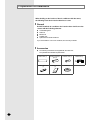
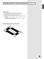
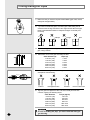
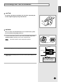
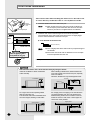
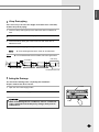
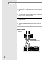
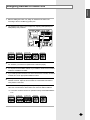
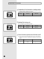
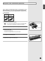
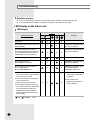
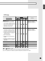
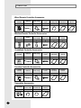
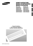
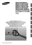
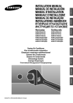
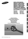
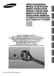
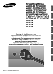
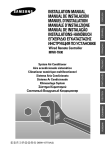
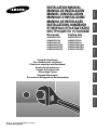
AVMKC020CA0 AVMKC032CA0 AVMKC040CA0 AVMKC020EA(B)0 AVMKC026EA(B)0 AVMKC035EA(B)0 ENGLISH ESPAÑOL RUSSIAN E§§HNIKA System Air Conditioner Aire acondicionado sistemático Climatiseur numérique multifonctionnel Sistema Aria Condizionata Sistema Ar Condicionado Klimaanlage System ™‡ÛÙËÌ· ∫ÏÈÌ·ÙÈÛÌÔ‡ ëËÒÚÂÏÌ˚È ÇÓÁ‰Û¯Ì˚È äÓ̉ˈËÓÌ FRANÇAIS AVMKH020CA0 AVMKH032CA0 AVMKH040CA0 AVMKH020EA(B)0 AVMKH026EA(B)0 AVMKH035EA(B)0 ITALIANO Cooling only PORTUGUÊS Heat pump DEUTSCH INSTALLATION MANUAL MANUAL DE INSTALACIÓN MANUEL D’INSTALLATION MANUALE D’INSTALLZIONE MANUAL DE INSTALAÇÃO INSTALLATIONS-HANDBUCH E°XEIPI¢IO E°KATA™TA™H™ àçëíêìäñàü èé ìëíÄçéÇäÖ E S F I P D G R DB98-05170A(2) Contents Chapter Chapter 1 WAY CASSETTE IN S TALLATION ■ Preparation for Installation . . . . . . . . . . . . . . . . . . . . . . . . . . . . . . . 4 ■ Deciding on Where to Install the Indoor Unit . . . . . . . . . . . . . . . . . 5 ■ Indoor Unit Installation . . . . . . . . . . . . . . . . . . . . . . . . . . . . . . . . . . 7 ■ Purging the Unit . . . . . . . . . . . . . . . . . . . . . . . . . . . . . . . . . . . . . . . 8 ■ Electronic Expansion Valve Installation . . . . . . . . . . . . . . . . . . . . . 8 ■ Connecting the Refrigerant Pipe . . . . . . . . . . . . . . . . . . . . . . . . . . 9 ■ Cutting/Flaring the Pipes . . . . . . . . . . . . . . . . . . . . . . . . . . . . . . . 10 ■ Performing Leak Test & Insulation . . . . . . . . . . . . . . . . . . . . . . . . 11 ■ Drain Hose Installation . . . . . . . . . . . . . . . . . . . . . . . . . . . . . . . . . 12 ■ Connecting the Connection Cord . . . . . . . . . . . . . . . . . . . . . . . . . 14 ■ Assigning Address to Indoor Unit . . . . . . . . . . . . . . . . . . . . . . . . . 15 ■ Additional Functions . . . . . . . . . . . . . . . . . . . . . . . . . . . . . . . . . . . 16 ■ Bio-pure Filter Installation(Optional) . . . . . . . . . . . . . . . . . . . . . . . 17 ■ Troubleshooting . . . . . . . . . . . . . . . . . . . . . . . . . . . . . . . . . . . . . . 18 OPTIONAL ACCESSORIES ■ E-2 Parts List . . . . . . . . . . . . . . . . . . . . . . . . . . . . . . . . . . . . . . . . . . . 22 ENGLISH Chapter 1 WAY CASSETTE INSTALLATION ■ Preparation for Installation . . . . . . . . . . . . . . . . 4 ■ Deciding on Where to Install the Indoor Unit . . . 5 ■ Indoor Unit Installation . . . . . . . . . . . . . . . . . . . . 7 ■ Purging the Unit . . . . . . . . . . . . . . . . . . . . . . . . 8 ■ Electronic Expansion Valve Installation . . . . . . . 8 ■ Connecting the Refrigerant Pipe . . . . . . . . . . . . 9 ■ Cutting/Flaring the Pipes . . . . . . . . . . . . . . . . . 10 ■ Performing Leak Test & Insulation . . . . . . . . . . 11 ■ Drain Hose Installation . . . . . . . . . . . . . . . . . . 12 ■ Connecting the Connection Cord . . . . . . . . . . 14 ■ Assigning Address to Indoor Unit . . . . . . . . . . 15 ■ Additional Functions . . . . . . . . . . . . . . . . . . . . 16 ■ Bio-pure Filter Installation(Optional) . . . . . . . . 17 ■ Troubleshooting . . . . . . . . . . . . . . . . . . . . . . . 18 E-3 Preparation for Installation When deciding on the location of the air conditioner with the owner, the following restrictions must be taken into account. General Do NOT install the air conditioner in a location where it will come into contact with the following elements: ◆ ◆ ◆ ◆ ◆ Combustible gases Saline air Machine oil Sulphide gas Special environmental conditions If you must install the unit in such conditions, first consult your dealer. Accessories ◆ The following accessories are supplied with the indoor unit. The quantities are indicated in parentheses. Pattern sheet (1) Insulation refrigerant pipe (2) Insulation drain (1) Insulation drain hose (1) Installation manual (1) Rubber (8) NS OWNER’S INSTRUCTIO Splut-type Room E-4 Air Conditioner Flexible hose (1) ENGLISH Deciding on Where to Install the Indoor Unit Indoor Unit ◆ ◆ ◆ ◆ There must be no obstacles near the air inlet and outlet. Install the indoor unit on a ceiling that can support its weight. Maintain sufficient clearance around the indoor unit. Make sure that the water dripping from the drain hose runs away correctly and safely. ◆ The indoor unit must be installed in this way, that they are out of public access. (Not touchable by the users) Space Requirements for Indoor Unit E-5 Deciding on Where to Install the Indoor Unit (cont.) Drawing of the indoor unit Unit : mm No. E-6 Name Description 1 Liquid pipe connection ø6.35 Nipple 2 Gas pipe connection ø12.70 Flare 3 Drain pipe connection OD29 ID25 4 Power supply connection 5 Air discharge grille 6 Air suction grille Indoor Unit Installation ENGLISH It is recommended to install the refnet joint before installing the indoor unit. 1 Place the pattern sheet on the ceiling at the spot where you want to install the indoor unit. Note 2 3 ◆ Since the diagram is made of paper, it may shrink or stretch slightly due to temperature or humidity. For this reason, before drilling the holes maintain the correct dimensions between the markings; refer to page 6. Concrete Insert bolt anchors, use existing ceiling supports or construct a suitable support as shown in figure. Install the suspension bolts depending on the ceiling type. Insert Hole in anchor Hole in plug IMPORTANT ◆ Ensure that the ceiling is strong enough to support the weight of the indoor unit. Before hanging the unit, test the strength of each attached suspension bolt. ◆ If the length of suspension bolt is more than 1.5m, it is required to prevent vibration. 4 Suspension bolt(3/8" or M10) Ceiling support Not supplied Screw eight nuts to the suspension bolts making space for hanging the indoor unit. Washer(supplied) IMPORTANT You must install the suspension bolts more than four when installing the indoor unit. Rubber Check the level of the indoor unit by using a leveler or a vinyl tube filled with water. ◆ A tilt of the indoor unit may cause malfunction of a built-in float switch and water leaks. 6 Adjust the height of the indoor unit by using the gauge of dimensions. ◆ The air inlet side should be slightly higher than the air outlet side (approx. 5mm). The appropriate height from the ceiling surface is 25mm for the air inlet and 20mm for the air outlet. ◆ You should adjust the gauge of dimensions and the pattern sheet to fit the cutting dimensions of ceiling. ◆ Make sure that the indoor unit is installed at a level if the indoor unit slants too much, there can be water leaks. Tighten the upper part nuts. 8 Remove the gauge of dimensions after installing the indoor unit. Level Vinyl tube 25mm 7 Fasten the nut Air inlet Gauge of Dimensions 20mm 5 Air outlet Ceiling E-7 Purging the unit On delivery, the indoor unit is loaded with refrigerant gas. All this gas must therefore be purged before connecting the assembly piping. To purge the inert gas, proceed as follows. Unscrew the pinch pipe at the end of each refrigerant pipe. Result: Liquid refrigerant port Note All inert gas escapes from the indoor unit. ◆ To prevent dirt or foreign objects from getting into the pipes during installation, do NOT remove the pinch pipe completely until you are ready to connect the piping. Gas refrigerant port Electronic Expansion Valve Installation Nylon band Electronic Expansion valve body E-8 1 Connect a strainer to the "IN" pipe and fix it. 2 Fix the electronic expansion valve kit with 2 screws(TH4x12) as shown at the figure. 3 Connect the "OUT" pipe to the liquid refrigerant pipe. 4 Insulate the connection piping. A joint part of pipe needs double thickness of insulation. 5 Connect the electronic expansion valve cable to the main PCB of indoor unit. 6 The expansion valve has to be installed that the user has no access to it. (built-in type) ENGLISH Connecting the Refrigerant Pipe There are two refrigerant pipes of differing diameters: ◆ A smaller one for the liquid refrigerant ◆ A larger one for the gas refrigerant ◆ The inside of copper pipe must be clean & has no dust. 1 Remove the pinch pipe on the pipes and connect the assembly pipes to each pipe, tightening the nuts, first manually and then with a wrench, a spanner applying the following torque. Outer Diameter 6.35 mm (1/4") 9.52 mm (3/8") 12.70 mm (1/2") 15.88 mm (5/8") 19.05 mm (3/4") 22.23 mm (7/8") Note 2 Torque (kgf•cm) 144~176 333~407 504~616 630~770 990~1210 990~1210 Refrigerant oil Torque wrench Spanner Flare nut Union ◆ If the pipes must be shortened refer to page 10. Must use insulator which is thick enough to cover the refrigerant pipe to protect the condensate water on the outside of pipe falling onto the floor and the efficiency of the unit will be better. 3 Cut off any excess foam insulation. 4 Be sure that there must be no crack or wave on the bended area. 5 It would be necessary to double the insulation thickness(10mm or more) to prevent condensation even on the insulator when if the installed area is warm and humid. Insulation refrigerant pipe Clamp Insulation refrigerant pipe Gas refrigerant pipe Liquid refrigerant pipe E-9 Cutting/Flaring the Pipes 1 Make sure that you have the required tools available (pipe cutter, reamer, flaring tool and pipe holder). 2 If you wish to shorten the pipes, cut it with a pipe cutter, taking care to ensure that the cut edge remains at a 90° angle with the side of the pipe. Refer to the illustrations below for examples of edges cut correctly and incorrectly. O 90 Oblique Burr 3 To prevent any gas from leaking out, remove all burrs at the cut edge of the pipe, using a reamer. 4 Slide a flare nut on to the pipe and modify the flare. Outer Diameter (D) 6.35 mm (1/4") 9.52 mm (3/8") 12.70 mm (1/2") 15.88 mm (5/8") 19.05 mm (3/4") 22.23 mm (7/8") 5 6 Depth (A) 1.3mm 1.8mm 2.0mm 2.2mm 2.2mm 2.2mm Check that the flaring is correct, referring to the illustrations below for examples of incorrect flaring. Inclined Damaged Surface Cracked Uneven Thickness Align the pipes and tighten the flare nuts first manually and then with a wrench, applying the following torque. Outer Diameter 6.35 mm (1/4") 9.52 mm (3/8") 12.70 mm (1/2") 15.88 mm (5/8") 19.05 mm (3/4") 22.23 mm (7/8") E-10 Rough Torque (kgf•cm) 144~176 333~407 504~616 630~770 990~1210 990~1210 CAUTION ◆ In case of welding the pipe, you must weld with nitrogen gas blowing. ENGLISH Performing Leak Test & Insulation Leak Test To check for gas leaks on the indoor unit, check the connection part of each refrigerant pipe by using a leak detector. Insulation Once you have checked that there are no leaks in the system, you can insulate the piping and hose. 1 To avoid condensation problems, place T13.0 or thicker Acrylonitrile Butadien Rubber separately around each refrigerant pipe. Note No gap ◆ Always make the seam of pipes face upwards. NBR(T13.0 or thicker) Insulation 2 Wind insulating tape around the pipes. Indoor Unit 3 Finish wrapping insulating tape around the rest of the pipes leading to the outdoor unit. Be sure to overlap the insulation CAUTION Must fit tightly against body without any gap. E-11 Drain Hose Installation Care must be taken when installing the drain hose for the indoor unit to ensure that any condensate water is correctly drained outside. Liquid refrigerant port 1 Insert the flexible hose to the drain hose port. Note Gas refrigerant port 2 Indoor Unit Band(Not supplied) ◆ Attach the drain hose to the drain hose port with an adhesive for PVC and tape to prevent water leaks, then secure the hose with a band etc..(The band is not supplied with the air conditioner.) Install the drain hose so that its length can be as short as possible. Internal diameter of the drain hose should be the same or slightly bigger than the external diameter of the drain hose port. ◆ Inner diameter of the drain hose Adhesives 20mm(Outer diameter) Insulation drain hose Note CAUTION Must fit tightly against body without any gap. No gap 3 ◆ Give a slightly slant to the drain hose for proper drainage of condensate. ◆ Secure the drain hose with an adhesive for PVC and tape not to be separated from the unit. Wrap the drain hose with the insulation drain as shown in figure and secure it. CAUTION Check that the indoor unit is level with the ceiling by using the leveler. Install air ventilation to drain condensate water smoothly. When installing a flexible hose, install a flexible hose to be bent smoothly from a drain hose port, especially within 100-200mm. Otherwise, flexible hose may be damaged and leak. Air ventilation 20mm or more Band joint 1/100 or more 550mm or less 100-200mm Flexible hose Ceiling Ceiling Do not give the hose and upward gradient after the connection port. This will cause water to flow backwards when the unit is stopped, resulting in water leaks. Do not apply force to the piping on the unit side when connecting the drain hose. The hose should not be allowed to hang loose from its connection to the unit. Fasten the hose to a wall, frame or other support as close to the unit as possible. Support pieces Upward gradient 1~1.5m 1/100 or more Ceiling E-12 Ceiling ENGLISH Lift-up Drain piping If it is necessary to increase the height of the drain hose somewhat, install a lift-up drain piping. 1 Connect a lift-up drain pipe top to the drain hose with an adhesive for PVC. 2 Wrap the insulation drain with a vinyl tape. 3 Connect the lift-up drain pipe to the indoor unit drain hose with an adhesive for PVC. 4 Turn the lift-up drain piping, then adjust the height. Note Note ◆ If it is raised higher than 55cm, there can be water leaks. ◆ If a concentrated drain hose is installed, refer to the figure below. Drain clamp 1/100 or more slope 100mm or more Air ventilation Concentrated drain hose Testing the Drainage You should test drainage after completing the installation. Prepare a little water about 1.0 liter. 1 Open the cover water supply intake. 2 Pour water into the water supply intake. Air outlet CAUTION ◆ When maintaining the air conditioner, remove condensate water remained in the drain pan by using a drain port for maintenance. Leveler E-13 Connecting the Connection Cord The indoor unit is powered from the outdoor unit via the connection cord. 1 Remove the screw on the electrical component box and remove the cover plate. 2 Route the connection cord through the side of the indoor unit and connect the cable to terminals; refer to the figure below. 3 Route the other end of the cable to the outdoor unit through the ceiling & the hole on the wall. 4 Reassemble the electrical component box cover, carefully tightening the screw. Wiring Diagram Indoor Unit Next Indoor unit(Power) Next Indoor unit (Communication) Outdoor Unit Communication E-14 Power ENGLISH Assigning Address to Indoor Unit 1 Before installing the indoor unit, assign an address to the indoor unit according to the air conditioning system plan. 2 The address of the indoor unit is assigned by adjusting MAIN(SW02) and RMC(SW01) rotary switches. K1 K2 K3 K4 K5 K6 K7 K8 K9 K10 K11 K12 SW03 SW04 SW05 SW01 RMC SW02 MAIN 3 The MAIN address is for communication between the indoor unit and the outdoor unit. Therefore, you must set it to operate the air conditioner properly. 4 It is required to set the RMC address if you install the wired remote controller and/or the centralized controller. 5 If you install optional accessories such as the wired remote controller, centralized controller, etc. see an appropriate installation manual. 6 If an optional accessory is not installed, you do not have to set the RMC address. However, adjust K1 and K2 switches of the SW03 DIP switch to "ON" position in this case. 7 Set the MAIN address by adjusting the rotary switch(SW02) from 0 to F. Each indoor unit connected to the same outdoor unit must have different address. i. e. If an indoor unit does not have an optional accessory and its MAIN address is "4" K1 K2 K3 K4 K5 K6 K7 K8 K9 K10 K11 K12 SW03 SW04 SW05 SW01 RMC SW02 MAIN E-15 Additional Functions Compensation for lost temperature in heating operation K5 K6 K7 K8 ◆ Reduces the difference between an actual room temperature and a sensed temperature by the air conditioner when heating. Switch No. Switch ON Switch OFF K5 2°C compensation 5°C compensation SW04 Adjusting filter cleaning cycle K5 K6 K7 K8 ◆ You can adjust the cycle for filter sign indicator. Switch No. Switch ON Switch OFF K6 1000 hours 2000 hours SW04 Control of electronic expansion valve at the indoor unit off K9 K10 K11 K12 SW05 E-16 ◆ When an indoor unit off makes refrigerant noise, set K11 to OFF position to reduce the noise. However, if a distributor kit is installed, K11 must be at ON position. Switch No. Switch ON Switch OFF K11 Electronic expansion valve step 80 Electronic expansion valve step 0 (Sub cool control) ENGLISH Bio-pure Filter Installation (optional) The air conditioner can be fitted with a Bio-Pure or deodorizing filter to remove minute dust particles or odours. The service life of the filter is approximately three months depending on the time during which the air conditioner is used. Accessories 1 Bio-pure filter Deodorizing filter 1 1 Remove the vinyl packing from the filter. Note 2 Do not remove the packing from a bio-pure or deodorizing filter until you wish to use the filter, as it will lose its properties. Bio-pure filter Open the front grille by pulling the tabs on the grille. Deodorizing filter 3 Remove the front grille. 3-1 Remove the safety clips. 3-2 Open the front grille about 45° and pull it forward. 4 Insert Bio-Pure or deodorizing filter. 5 Reinstall the front grille and the safety clips. E-17 Troubleshooting Detection of errors ◆ If an error occurs during the operation, an LED flickers and the operation is stopped except the LED. ◆ If you re-operate the air conditioner, it operates normally at first, then detect an error again. LED Display on the indoor unit LED Display Indicators Abnormal conditions Operating Green Power reset Red X Error of temperature sensor in indoor unit (OPEN/SHORT) X Error of heat exchanger sensor in indoor unit Error of heat exchanger OUT sensor in indoor unit Error of outlet temperature sensor in indoor unit (OPEN/SHORT): For heat pump models only X X X Error of mixed operation X Error of indoor fan motor: Below 450RPM for 15 minutes X Error of outdoor temperature sensor Error of COND sensor Error of DISCHARGE sensor X X X X X X X X X X Displayed on appropriate indoor unit which is operating X X X Displayed on appropriate indoor unit which is operating Displayed on outdoor unit 1. Error of indoor unit: Displayed on the indoor unit regardless of operation 2. Indoor unit receiving the communication error from outdoor unit 4. When sending the communication error from outdoor unit due to the mismatching of the communication numbers and installed numbers after completion of tracking (communication error for more than 2 minutes) ● On E-18 Flickering X Off Displayed on appropriate indoor unit which is operating X 1. No communication for 2 minutes between indoor unit and outdoor unit (communication error for more than 2 minutes) 3. Outdoor unit tracking 3 minute error Displayed on appropriate indoor unit which is operating X X X 2. Error of outdoor unit: Displayed on the indoor unit which is operating ENGLISH LED Display Indicators Abnormal conditions Operating Green Red Self-diagnostic error (including the indoor unit not detected) Displayed on appropriate indoor unit which is operating Displayed on outdoor unit 1. Error of electronic expansion valve close 2. Error of electronic expansion valve open X X 3. Breakaway of EVA OUT sensor 4. Breakaway of EVA IN sensor 5. Breakaway of COND MID sensor Displayed on appropriate indoor unit which is operating Displayed on outdoor unit 6. 2nd detection of refrigerant completely leak 7. 2nd detection of high temperature COND 8. 2nd detection of high temperature DISCHARGE 9. COMP DOWN due to 2nd detection of low pressure switch X X Error of float switch X X Error of setting option switches for optional accessories X X 10. Error of reverse phase 11. Compressor down due to 6th detection of freezing 12. Self-diagnosis of condensation sensor (G8, G9) 13. Compressor down due to condensation ratio control EEPROM error X X X X EEPROM option error ● On Flickering X Off ◆ If you turn off the air conditioner when the LED is flickering, the LED is also turned off. ◆ If you re-operate the air conditioner, it operates normally at first, then detects an error again. E-19 Troubleshooting (cont.) Wired remote controller ◆ If an error occurs, is displayed on the wired remote controller. ◆ If you would like to see an error code, press the Test button. Display Explanation Error of communication between the outdoor unit and the wired remote controller Remark Communication errors Error of communication between the indoor unit and the wired remote controller x Breakaway of indoor unit eva sensor x Breakaway of indoor unit eva out sensor x Open error of electronic expansion valve x x Close error of electronic expansion valve x x Error of float switch x OPEN/SHORT error of eva in sensor in indoor unit x OPEN/SHORT error of eva out sensor in indoor unit x EEPROM error x EEPROM option error x Error of fan starting Displays related to indoor unit (x : 0~F) Breakaway of eva mid and eva out sensors in indoor unit OPEN/SHORT error of room sensor in indoor unit Error of outdoor unit For the details, refer to the installation manual of the outdoor unit. The order of priority : EA → Eb → Cx → dx → bx → Ax → Fx → ox → qx → rx → sx → tx → Ux → vx → Eo - In case that the same error displays from multi-indoor units, the one having the faster address has the priority. E-20 ENGLISH Chapter OPTIONAL ACCESSORIES ■ Parts List . . . . . . . . . . . . . . . . . . . . . . . . . . . . . . . . . 22 E-21 Parts List Wired Remote Controller Accessories Wired remote controller Cable-tie Cable clamp 1 2 5 M4x16 tapped Indoor unit power screw drawing cable Owner’s instructions Installation manual 1 1 1 Owner’s instructions Installation manual 2 1 1 7 Wireless Remote Controller Accessories Wireless remote controller Battery 1 2 Remote STS 2S-2x10 control holder tapped screw 1 Centralized Controller Accessories Centralized controller Cable-tie Cable clamp M4x16 tapped screw Owner’s instructions Installation manual 1 2 5 7 1 1 Function Controller Accessories Function controller Cable-tie Cable clamp M4x16 tapped screw Owner’s instructions Installation manual 1 2 6 7 1 1 Transmitter Accessories E-22 Transmitter Transmitter power cable Transmitter communication cable Installation manual 1 1 1 1 ENGLISH Memo E-23 THIS AIR CONDITIONER IS MANUFACTURED BY: ESTE AIRE ACONDICIONADO HA SIDO FABRICADO POR: CE CLIMATISEUR EST FABRIQUE PAR: QUESTO CONDIZIONATORE D’ARIA È PRODOTTO DA: ESTE APARELHO DE AR CONDICIONADO É FABRICADO POR: DIESE KLIMAANLAGE IST FABRIZIERT VON: AYTH H ™Y™KEYH KATA™KEYA™THKE A¶O: ùíéí äéçÑàñàéçÖê àáÉéíéÇãÖç îàêåéâ: ELECTRONICS Printed in Korea