1
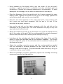
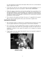
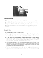
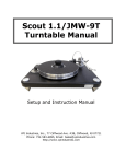
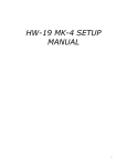
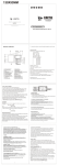
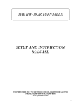
Scout 2/JMW-9T Turntable Manual Setup and Instruction Manual VPI Industries, Inc., 77 Cliffwood Ave. #3B, Cliffwood, NJ 07721 phone: 732-583-6895 fax: 732-946-8578 http://www.vpiindustries.com Important: Read Before Proceeding! Read and follow the Safety Instructions below. Save all packing materials. The Scout should only be moved or shipped in its original packaging to reduce the risk of damage in transit. The Scout must be placed on a flat, level surface. This will make setup easy, provide better sound quality, and put less strain on the main bearing. Safety Instructions Follow the instructions below to reduce risk of electrical hazard or injury. • To avoid electrical shock, do not open the motor housing. • If the power cord provided with the Scout does not reach an outlet, use a heavy-duty, grounded extension cord. • To avoid electrical shock, always plug the Scout into a grounded outlet. • Do not expose the Scout to rain or excessive moisture. • Do not touch the male pivot point of the tonearm assembly. It is extremely sharp. Follow the instructions below to avoid damage to the Scout • Do not leave the Scout running unattended. • Use the Scout in a well-ventilated area. • Place the Scout on a firm surface to allow proper ventilation to occur. Introduction The Scout turntable is a precision instrument featuring the new Tapered arm tube version of the JMW-9 tonearm. It has been thoroughly tested and run for at least 4 hours. The speed accuracy, wow, flutter, and rumble have been checked, and this unit meets all of our specifications. Minimum Specifications Wow and flutter Less than .02%. Rumble Greater than 78db down. Speed accuracy Within .1%. Total weight 32 pounds. Platter run out +/- .001 inch. Product Specifications 600 RPM AC synchronous drive motor. Drive belt custom-made for VPI. Aluminum cone feet with stainless steel ball bearings on the bottoms. Solid acrylic platter with bronze bushings and Peek thrust surface. Platter sits on 60 Rockwell-hardened shaft and chrome-hardened ball bearing. Complete and return the warranty card. The warranty does not take effect until the warranty card is returned. Unpacking the Box The turntable and tonearm are packed very carefully to avoid damage during shipping. It is important that you save the packing materials and box to use for shipping or moving the Scout. 1. Remove the 2 foam side pieces and foam block in the center. 2. Make space for the Scout and remove the chassis from the box. Put the chassis down on a solid surface. Complete and return the warranty card. The warranty does not take effect until the warranty card is returned. 3. Remove and set aside the items in the next layer: Alignment Jig. Record clamp. Power cord. Bag containing screwdrivers and screws for mounting the cartridge. 4. Remove the pieces of foam covering the tonearm, then carefully remove the tonearm and set it down in a safe place. Use caution with the tonearm’s delicate wires and Lemo connector. 5. Remove the turntable platter and motor. Be very careful not to hit or damage the motor pulley. It measured +/- .0005” when it was tested at the factory. Try not to disturb it at all. Setting up the Scout The Scout must be placed on a flat, level surface. This will make setup easy, provide better sound quality, and put less strain on the main bearing. 1. Place the turntable chassis, with the square cutout on the left, on the shelf or stand where it will be used. The better isolation you provide the Scout, the better it will sound. We highly recommend a 1 to 3 inch thick maple shelf sitting on rubber isolator feet for this purpose. 2. Remove the tape from the spindle hole on the turntable platter and place the platter on the spindle. The platter bearing is lubricated; no additional lubrication is needed for at least one year. 3. Connect the power cord to the motor, then place the motor, with the power cord at the rear, next to the square cutout of the turntable chassis. 1 4. Lift the chassis and place it over the power cord. The motor should extend approximately .25 inch from the side of the turntable chassis. 5. Place the drive belt around the platter and around the pulley on the motor. The belt does not have to be level on the platter. It will self-level when the platter starts rotating. 6. For 33 RPM operation, place the belt on the upper part of the pulley. For 45 RPM operation, place the belt on the lower, wider part of the pulley. The center groove in each diameter is the correct speed. To determine the precise speed, use a strobe disc. The VPI Synchronous Drive System speed controller provides the ultimate speed accuracy and best sound. Check with your dealer about availability. 7. Verify the turntable is level by using a 9 or 12-inch bubble level front-to-back and side-to-side on the platter. If it is not level, rotate the aluminum cone feet up or down. If you must turn the Scout feet more than three full turns, level the shelf or platform the table sits on first. Installing and Aligning the Cartridge • Remove the protective cover from the male pivot point on the arm base assembly. To avoid injury, do not touch the male pivot point. It is extremely sharp. In addition, skin oils can blemish and cause corrosion to the assembly. • For cartridges with threaded mounting holes, use the screws supplied by the cartridge manufacturer. Other screws may not fit properly and may cause damage to the threads and cartridge. • To avoid damage to the tonearm, use one of the washers supplied by VPI under the screw heads. • For cartridges with pass-through mounting holes, use the hardware supplied with the tonearm. Be sure to use washers under the screw heads. • The tonearm wires are color-coded as follows: Red right hot Green right ground White or Black left hot Blue left ground. If your phono section inverts phase, the hot color becomes the ground color. 2 • Using tweezers or fine-tipped pliers, grip the center of the red wire’s connector not the wire itself and push it onto the cartridge’s right hot terminal pin. Connect the remaining connectors in the same way. To avoid damage to the cartridge, do not push the connectors all the way on. • Place the Alignment Jig on the spindle with the V-groove against the male bearing shaft. Tighten the screws of the jig so it fits snugly against the male bearing shaft and over the record spindle. • Place the arm tube assembly on the male pivot point, using caution with the 4-color wire and Lemo connector. Set the arm in its rest. If the cartridge has a guard, remove it. • Line up the red dot on the Lemo connector with the red dot on the receptacle on the junction box. The Lemo connector can plug in only one way and should not be forced. • Swing the tonearm over the jig so the stylus is as close as possible to the dot in the center of the grid. Set the counterweight for enough downward force to keep the stylus from moving when resting on the jig. • Look down at the cartridge and align it between the lines of the grid. Be careful to align the cartridge and not the tonearm headshell. You should have the diamond stylus on the white dot and the cantilever lined up with the lines on the grid. • Adjust the cartridge mounting screws and the counterweight as needed until the cartridge is centered between the grid lines and the stylus is resting on the dot of the grid. The picture below shows the setup, the jig is in white for clarity, yours is black. • When the cartridge is properly positioned, tighten the cartridge mounting screws and remove the alignment jig. 3 Setting the Anti-Skating – Two Solutions Anti-skating is one of the least understood forces acting on a tonearm. Skating force is created by friction between the stylus and the record, causing a force vector in a direction towards the center of the record when the headshell of the tonearm has an offset angle. Putting a stylus down on a flat, groove less record will cause the arm to move toward the center of the record. Arm manufacturers have tried to compensate for this force, but that is impossible because the force is constantly changing as the music and velocity change. VPI has conducted careful listening tests and determined that every tonearm we tried sounded better with its mechanical anti-skating disabled and the tracking force very slightly increased.. VPI has a unique solution to anti-skating: the coiled wire of the JMW Memorial Tonearm acts as a spring and pushes the arm back without affecting the sound quality. You now have the option of installing a mechanical anti-skate for those that want it. • Adjust the counterweight so there is no down force on the cartridge. • Swing the tonearm toward the spindle and release it. The arm should swing out toward the outer edge of the turntable. If you try adjusting the anti-skate with a groove less record, you will ruin the twist in the tonearm wire and void your warranty. Do this with the mechanical anti-skate if you want that much anti-skate. • If additional anti-skate is wanted you can go to the mechanical anti-skate we supply. Setting the Tracking Force and Tonearm Height Tracking force is adjusted by moving the tonearm counterweight forward and back on its shaft. If your cartridge is heavy and the counterweight is all the way back, you can order a heavier weight from your dealer. The JMW-9T Tonearm does not have a built-in tracking force gauge. We recommend that you use a Shure Stylus Force Gauge or good digital gauge. • Place the gauge on the platter (no record) • Loosen the set screws in the base of the tonearm and raise the arm so it looks parallel to the platter when it is on the stylus force gauge. To adjust the arm height, loosen the setscrews on the base of the arm assembly and 4 turn the adjustment wheel above the base. When the arm is at the desired height, tighten the screws. • If you do not raise the arm when doing this you will be between .2 to .4 grams light when you are on the record. THIS IS VERY IMPORTANT!! • Follow the gauge instructions and set the tracking force according to the cartridge manufacturer’s recommendation. We recommend always going to the high side of tracking force. High frequency vibrations on a light-tracking cartridge can cause more damage to the grooves of a record than running a cartridge at a heavy setting. • Put a record on the platter and lower the arm so it is parallel to the record. Now you will be tracking at the force you set and not a lighter force. Setting the Azimuth • Set a fireplace match or coffee stirrer (something light and about 6” long) into the groove behind the mounting screws on the tonearm headshell. • If it is not level, use the supplied Allen wrench to loosen the setscrew on the counterweight and rotate the counterweight around the shaft until the headshell is parallel to the record. Be careful not to change the tracking force setting. • If you prefer you can rotate the azimuth ring to set azimuth instead of rotating the counterweight. AZIMUTH RING 5 Playing Records Before playing a record, make sure that all of the tonearm screws are tight. Place the black washer on the platter, then the record, then the record clamp. Always turn off the turntable before installing the record clamp. Press the power button on the motor. Sit down and enjoy listening to your records! General Use • Allow at least 20 hours of break-in time. • The motor will make some low-level noise. This will not get into the system. The motor and bearings will become quieter as you use your Scout. Place the motor on a mouse pad for better isolation • If you notice hum in the system, remove the turntable to phono section interconnects and replace them with very cheap, standard VCR interconnects. These are well shielded and should eliminate the hum. If the hum goes away, get quality, well shielded interconnects. • After at least one year of use, the platter bearing and motor will need to be lubricated. For the platter, use a ¼” blob of white lithium grease placed on the ball. For the motor, use 1 drop of 40-weight motor oil below the black drive pulley and right on the brass piece. • We find the table sounds best with no mat on the platter, you can experiment with mats but you need to adjust the VTA setting when doing this. 6 Additional Items Available from Your Dealer • The VPI Synchronous Drive System power supply provides a major increase in musicality by feeding the synchronous motor in your table a perfectly stable wave form at the frequency you choose. The SDS lets you change speed electronically. • 300 RPM Scoutmaster motor - $150.00 • Classic aluminum platter - $800.00 • TNT-Mini isolator feet - $300.00 VPI Industries, Inc. Limited Warranty VPI Industries, Inc. (VPI) warrants this unit against defects in materials and/or workmanship for three (3) years from the date of purchase by the original retail purchaser. VPI’s sole obligation under this warranty is limited to the repair or replacement, at VPI’s option, of any part(s) found to be defective. VPI’s obligation to repair or replace defective parts is the purchaser’s sole and exclusive remedy, and VPI shall not be liable for any direct or indirect injury and/or property damage arising out of the use of the product or defect in or failure of the product. This warranty does not extend to any unit whose serial number has been defaced or altered. Any product that VPI determines causes a defect or malfunction due to incorrect installation, modification, misuse, or servicing by the purchaser, or service technician not authorized by VPI to perform such service will not be warranted. This warranty does not cover trivial or cosmetic defects that do not impair the unit’s normal function. VPI reserves the right to make changes in this product without assuming any obligation to install such change in any product previously manufactured. This warranty to repair or replace defective parts is in lieu of all other express or implied warranties of merchantability or fitness for a particular purpose. There are not warranties that extend beyond the description herein. Some states do not allow exclusion of implied warranties or limitation of incidental or consequential damages, so the above exclusion or limitations may not apply to you. This warranty gives you specific legal rights, and you may also have other rights that vary from state to state. 7