1
INSTALLATION MANUAL
FOR SEA TEL 3011W-91 BROADBAND-AT-SEA
TRANSMIT / RECEIVE SYSTEM WITH SELECTABLE CO-POL OR
CROSS-POL RECEIVE
Sea Tel, Inc.
4030 Nelson Avenue
Concord, CA 94520
Tel: (925) 798-7979
Fax: (925) 798-7986
Web: http://www.cobham.com/seatel
January 30, 2012
Sea Tel Europe
Unit 1, Orion Industrial Centre
Wide Lane, Swaythling
Southampton, UK S0 18 2HJ
Tel: 44 (0)23 80 671155
Fax: 44 (0)23 80 671166
Web: http://www.cobham.com/seatel
Sea Tel Inc is also doing business as Cobham Antenna Systems
Document. No. 136407 Revision A
These commodities, technology or software were exported from the United
States in accordance with the Export Administration Regulations. Diversion
contrary to U.S. law is prohibited.
Sea Tel Marine Stabilized Antenna systems are manufactured in the United
States of America.
Sea Tel is an ISO 9001:2008 registered company.
Certificate Number 13690 issued March 14, 2011.
R&TTE
CE
The Series 10 Family of Marine Stabilized Antenna Pedestals with DAC-2202 or DAC-2302
Antenna Control Unit complies with the requirements of directive 1999/5/EC of the European
Parliament and of the Council of 9 March 1999 on Radio equipment and Telecommunication
Terminal Equipment. A copy of the R&TTE Declaration of Conformity for this equipment is
contained in this manual.
The Sea Tel Series 09 & 10 antennas will meet the off-axis EIRP spectral density envelope set forth in FCC 47
C.F.R. § 25.222(a)(1) when the input power density limitations, listed in our FCC Declaration, are met..
These antenna systems also contain FCC compliant supervisory software to continuously monitor the pedestal
pointing accuracy and use it to control the “Transmit Mute” function of the satellite modem to satisfy the
provisions of FCC 47 C.F.R. § 25.222(a)(l)(iii).
Copyright Notice
Copyright © 2012 Sea Tel Inc All Rights Reserved. The information contained in this document is proprietary to Sea Tel,
Inc.. This document may not be reproduced or distributed in any form without prior written consent of Sea Tel, Inc. The
information in this document is subject to change without notice. Sea Tel Inc, is also doing business as Cobham Antenna
Systems.
This document has been registered with the U.S. Copyright Office.
Revision History
REV
ECO#
Date
Description
By
A
N/A
January 30, 2012
Production Release
MDN
ii
Table of Contents
1.
2.
3.
3011W-91 Installation Manual
3011 SYSTEM CONFIGURATION(S) ............................................................................................................................................... 1-1
1.1. SYSTEM CABLES ............................................................................................................................................................................................. 1-1
1.2. OTHER INPUTS TO THE SYSTEM .................................................................................................................................................................. 1-1
1.3. SIMPLIFIED BLOCK DIAGRAM OF A 3011 SYSTEM .................................................................................................................................. 1-1
1.4. DUAL ANTENNA CONFIGURATION ............................................................................................................................................................. 1-2
1.5. DUAL ANTENNA ARBITRATOR ..................................................................................................................................................................... 1-3
1.6. OPEN ANTENNA-MODEM INTERFACE PROTOCOL (OPENAMIP™) SPECIFICATION:........................................................................ 1-3
1.6.1. Overview: ........................................................................................................................................................................................1-3
1.6.2. Interface requirements: .........................................................................................................................................................1-4
1.6.3. Utilized OpenAMIP Commands: ........................................................................................................................................1-4
SITE SURVEY .................................................................................................................................................................................................. 2-1
2.1. SITE SELECTION ABOARD SHIP ................................................................................................................................................................... 2-1
2.2. ANTENNA SHADOWING (BLOCKAGE) AND RF INTERFERENCE .............................................................................................................. 2-1
2.3. MOUNTING FOUNDATION ........................................................................................................................................................................... 2-2
2.3.1. Mounting on Deck or Deckhouse......................................................................................................................................2-2
2.3.2. ADE Mounting Considerations ...........................................................................................................................................2-2
2.3.3. Sizing of the support pedestal ............................................................................................................................................2-2
2.4. MOUNTING HEIGHT ...................................................................................................................................................................................... 2-3
2.5. MAST CONFIGURATIONS ............................................................................................................................................................................. 2-3
2.5.1. Vertical Masts ..............................................................................................................................................................................2-4
2.5.2. Raked Masts..................................................................................................................................................................................2-4
2.5.3. Girder Masts .................................................................................................................................................................................2-4
2.5.4. Truss Mast .....................................................................................................................................................................................2-5
2.6. SAFE ACCESS TO THE ADE .......................................................................................................................................................................... 2-5
2.7. BELOW DECKS EQUIPMENT LOCATION ..................................................................................................................................................... 2-5
2.8. CABLES ............................................................................................................................................................................................................. 2-5
2.8.1. ADE/BDE Coaxial Cables........................................................................................................................................................2-6
2.8.2. Antenna Power Cable ..............................................................................................................................................................2-6
2.8.3. Air Conditioner Power Cable ...............................................................................................................................................2-6
2.8.4. ACU Power Cable/outlet ........................................................................................................................................................2-6
2.8.5. Gyro Compass Cable ................................................................................................................................................................2-6
2.9. GROUNDING.................................................................................................................................................................................................... 2-6
INSTALLATION ............................................................................................................................................................................................. 3-1
3.1. UNPACKING AND INSPECTION .................................................................................................................................................................... 3-1
3.2. ASSEMBLY NOTES AND WARNINGS ........................................................................................................................................................... 3-1
3.3. INSTALLING THE ADE ................................................................................................................................................................................... 3-2
3.3.1. Prepare the 50”, 60”, 66” or 76” Radome Assembly ................................................................................................3-2
3.3.2. Installing the 50, 60 or 66” Radome Assembly..........................................................................................................3-3
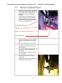
3.4. REMOVING THE SHIPPING/STOW RESTRAINTS PRIOR TO POWER-UP .............................................................................................. 3-6
3.4.1. Removing the AZ Shipping/Stow Restraint ..................................................................................................................3-6
3.4.2. Removing the EL Shipping/Stow Restraint ...................................................................................................................3-7
3.4.3. Removing the CL Shipping/Stow Restraint ...................................................................................................................3-8
3.5. CABLE INSTALLATION ................................................................................................................................................................................... 3-9
3.5.1. Shipboard Cable Installation ...............................................................................................................................................3-9
3.6. INSTALLING THE BELOW DECKS EQUIPMENT. .......................................................................................................................................... 3-9
3.6.1. General Cautions & Warnings .............................................................................................................................................3-9
3.6.2. Preparing BDE Location .........................................................................................................................................................3-9
3.6.3. Installing the Below Deck Equipment .........................................................................................................................3-10
v
3011W-91 Installation Manual
Table of Contents
CONNECTING THE BELOW DECKS EQUIPMENT ..................................................................................................................................... 3-10
3.7.1. Connecting the ADE AC Power Cable ......................................................................................................................... 3-10
3.7.2. Connecting the BDE AC Power Cables ....................................................................................................................... 3-10
3.7.3. Connecting the ADE IF Coaxes ...................................................................................................................................... 3-10
3.7.4. Connect the Modem TXIF Coax .................................................................................................................................... 3-10
3.7.5. Antenna Control Unit Connections .............................................................................................................................. 3-10
3.7.6. 133BURadio Control Serial Cable .................................................................................................................................. 3-11
3.7.7. Terminal Mounting Strip (TMS) Connections ......................................................................................................... 3-11
3.7.8. Other BDE connections ...................................................................................................................................................... 3-14
3.8. FINAL CHECKS.............................................................................................................................................................................................. 3-14
3.8.1. Visual/Electrical inspection ............................................................................................................................................... 3-14
3.8.2. Electrical - Double check wiring connections ......................................................................................................... 3-15
3.9. POWER-UP ................................................................................................................................................................................................... 3-15
3.10. 61BANTENNA MAINTENANCE ................................................................................................................................................................ 3-15
3.10.1. Balancing the Antenna ........................................................................................................................................................ 3-15
3.10.2. Fine Balance and Monitoring Motor Drive Torque .............................................................................................. 3-16
BASIC SETUP OF THE ACU .................................................................................................................................................................. 4-1
4.1. OPERATOR SETTINGS..................................................................................................................................................................................... 4-1
4.2. SETUP PARAMETER DISPLAY AND ENTRY MENUS. .................................................................................................................................. 4-1
4.3. DEFAULT SETUP PARAMETERS FOR YOUR ANTENNA............................................................................................................................... 4-1
4.4. SAVE NEW PARAMETERS...................................................................................................................................................................... 4-2
SETUP – SHIPS GYRO COMPASS ...................................................................................................................................................... 5-1
5.1. GYRO TYPE ................................................................................................................................................................................................... 5-1
5.2. UPDATING THE GYRO TYPE PARAMETER ................................................................................................................................................ 5-1
5.3. IF THERE IS NO SHIPS GYRO COMPASS .................................................................................................................................................... 5-1
SETUP – TRACKING RECEIVER - VSAT ........................................................................................................................................ 6-1
6.1. DETERMINING THE IF TRACKING FREQUENCY (MHZ) ........................................................................................................................... 6-1
6.2. KHZ ................................................................................................................................................................................................................... 6-1
6.3. FEC ................................................................................................................................................................................................................... 6-1
6.3.1. L-Band SCPC Receiver............................................................................................................................................................. 6-1
6.4. TONE................................................................................................................................................................................................................. 6-1
6.4.1. VSAT Application ....................................................................................................................................................................... 6-1
6.5. VOLT ................................................................................................................................................................................................................. 6-2
6.5.1. VSAT Application ....................................................................................................................................................................... 6-2
6.6. SAT SKEW..................................................................................................................................................................................................... 6-2
6.7. NID .................................................................................................................................................................................................................. 6-2
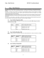
SETUP – BAND SELECTION .................................................................................................................................................................. 7-1
7.4. CROSS-POL ONLY QUAD-BAND LNB ......................................................................................................................................................... 7-2
7.1. CROSS-POL AND CO-POL SINGLE-BAND LNBS...................................................................................................................................... 7-2
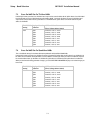
7.4. CROSS-POL AND CO-POL QUAD-BAND LNBS ....................................................................................................................................... 7-3
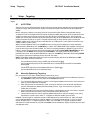
SETUP – TARGETING ................................................................................................................................................................................ 8-1
8.1. AUTO TRIM ................................................................................................................................................................................................. 8-1
8.2. MANUALLY OPTIMIZING TARGETING ........................................................................................................................................................ 8-1
8.3. EL TRIM.......................................................................................................................................................................................................... 8-2
8.4. AZ TRIM ........................................................................................................................................................................................................ 8-2
SETUP – HOME FLAG OFFSET............................................................................................................................................................. 9-1
9.1. ELECTRONIC CALIBRATION OF RELATIVE ANTENNA POSITION (HOME FLAG OFFSET).................................................................... 9-1
9.1.1. You Found a Large AZ TRIM value:.................................................................................................................................. 9-1
3.7.
4.
5.
6.
7.
8.
9.
vi
Table of Contents
10.
11.
12.
13.
14.
3011W-91 Installation Manual
9.1.2. You Observe “Home” Pointing is LEFT of the Bow-line: .........................................................................................9-2
9.1.3. You Observe “Home” Pointing is RIGHT of the Bow-line: .....................................................................................9-2
9.1.4. To Enter the HFO value in the DAC_2202: ...................................................................................................................9-3
9.2. MECHANICAL CALIBRATION OF RELATIVE ANTENNA POSITION (HOME FLAG OFFSET) ................................................................. 9-4
SETUP – SEARCHING ............................................................................................................................................................................. 10-1
10.1. SEARCHING OPERATION .............................................................................................................................................................................10-1
10.1.1. Default Standard (Box) Search Pattern .......................................................................................................................10-1
10.1.2. Inclined Orbit Search Pattern ..........................................................................................................................................10-2
10.1.3. No Gyro Search Pattern ......................................................................................................................................................10-3
10.2. CHANGING THE SEARCH PARAMETERS ....................................................................................................................................................10-4
10.2.1. AUTO THRES .............................................................................................................................................................................10-4
10.2.2. EL STEP SIZE ............................................................................................................................................................................10-4
10.2.3. AZ STEP SIZE ...........................................................................................................................................................................10-4
10.2.4. STEP INTEGRAL .......................................................................................................................................................................10-4
10.2.5. SEARCH INC ..............................................................................................................................................................................10-5
10.2.6. SEARCH LIMIT .........................................................................................................................................................................10-5
10.2.7. SEARCH DELAY ........................................................................................................................................................................10-5
10.2.8. SWEEP INC ................................................................................................................................................................................10-5
10.3. SAVE NEW PARAMETERS ...................................................................................................................................................................10-5
SETUP – BLOCKAGE & RF RADIATION HAZARD ZONES .............................................................................................. 11-1
11.1. RADIATION HAZARD AND BLOCKAGE MAPPING (AZ LIMIT PARAMETERS) ...................................................................................11-1
11.2. SAVE NEW PARAMETERS ...................................................................................................................................................................11-4
SETUP – MODEM CONNECTIONS, SETUP AND TEST ..................................................................................................... 12-1
12.1. JUMPER SELECTION .....................................................................................................................................................................................12-1
12.2. IDIRECT MODEMS ......................................................................................................................................................................................12-2
12.3. COMTECH MODEMS ...................................................................................................................................................................................12-2
12.4. HUGHES MODEMS ......................................................................................................................................................................................12-3
12.5. STM MODEMS............................................................................................................................................................................................12-3
12.6. CONNECTIONS (ACU TO SATELLITE MODEM) ......................................................................................................................................12-3
12.6.1. iDirect Modems .......................................................................................................................................................................12-3
12.6.3. Hughes Modems .....................................................................................................................................................................12-3
12.6.4. STM Modems ...........................................................................................................................................................................12-4
12.6.5. SYSTEM TYPE parameter ....................................................................................................................................................12-4
12.7. BLOCKAGE SIMULATION TEST - DAC-2202 ......................................................................................................................................12-5
12.8. TESTING THE SATELLITE MODEM LOCK INPUT - DAC-2202 .........................................................................................................12-6
12.9. SAVE NEW PARAMETERS ...................................................................................................................................................................12-6
SETUP – OPTIMIZING POLARITY & CROSS-POL ISOLATION ................................................................................... 13-1
13.1. SAT SKEW SETTING .....................................................................................................................................................................................13-1
13.2. POLARITY ANGLE (POLANG) PARAMETERS...........................................................................................................................................13-1
13.3. OPTIMIZING AUTO-POLARIZATION ON RECEIVE SIGNAL....................................................................................................................13-1
13.4. OPTIMIZING AUTO-POLARIZATION CROSS-POL ISOLATION ..............................................................................................................13-2
SETUP – OTHER PARAMETERS ....................................................................................................................................................... 14-1
14.1. SETUP PARAMETER DISPLAY AND ENTRY MENUS.................................................................................................................................14-1
14.2. 5V OFFSET (MAY NOT BE IN YOUR SOFTWARE) .................................................................................................................................14-1
14.3. 5V SCALE (MAY NOT BE IN YOUR SOFTWARE) ....................................................................................................................................14-1
14.4. REMOTE COMMAND ............................................................................................................................................................................14-1
14.5. REMOTE MONITOR ...............................................................................................................................................................................14-1
14.6. TO DISABLE/ENABLE DISHSCAN® ..........................................................................................................................................................14-1
vii
3011W-91 Installation Manual
15.
16.
17.
18.
Table of Contents
14.7. SATELLITE REFERENCE MODE ................................................................................................................................................................... 14-2
14.8. REMOTE PARAMETERS ....................................................................................................................................................................... 14-2
FUNCTIONAL TESTING ....................................................................................................................................................................... 15-1
15.1. ACU / ANTENNA SYSTEM CHECK ........................................................................................................................................................... 15-1
15.2. LATITUDE/LONGITUDE AUTO-UPDATE CHECK ..................................................................................................................................... 15-1
15.3. HEADING FOLLOWING ................................................................................................................................................................................ 15-1
15.4. BLOCKAGE SIMULATION TEST .................................................................................................................................................................. 15-1
15.5. FOUR QUADRANT TEST TRACKING.......................................................................................................................................................... 15-2
15.6. BLOCKAGE SIMULATION TEST .................................................................................................................................................................. 15-3
15.7. TEST BROADBAND OPERATION ................................................................................................................................................................ 15-3
15.8. TEST VOICE OVER IP (VOIP) OPERATION ............................................................................................................................................ 15-4
INSTALLATION TROUBLESHOOTING ........................................................................................................................................ 16-1
16.1. WARRANTY INFORMATION ....................................................................................................................................................................... 16-1
16.2. TROUBLESHOOTING THE ACU ................................................................................................................................................................. 16-1
16.2.1. ACU display is blank .............................................................................................................................................................. 16-2
16.2.2. ACU Status displays "REMOTE NOT RESPONDING" ............................................................................................ 16-2
16.3. TROUBLESHOOTING SHIPS GYRO COMPASS PROBLEMS ...................................................................................................................... 16-2
16.3.1. STEP-BY-STEP........................................................................................................................................................................... 16-2
16.3.2. 1:1 SYNCHRO ............................................................................................................................................................................ 16-2
16.3.3. 360:1 Synchro .......................................................................................................................................................................... 16-3
STOWING THE ANTENNA FOR UNDERWAY WITH POWER OFF ............................................................................ 17-1
17.1. INSTALLING THE STOW RESTRAINTS....................................................................................................................................................... 17-1
17.1.1. Installing the AZ Shipping/Stow Restraint ............................................................................................................... 17-1
17.1.2. Installing the EL Shipping/Stow Restraint................................................................................................................. 17-2
17.1.3. Installing the CL Shipping/Stow Restraint ................................................................................................................ 17-3
17.2. REMOVING THE SHIPPING/STOW RESTRAINTS PRIOR TO POWER-UP............................................................................................ 17-4
17.2.1. Removing the AZ Shipping/Stow Restraint .............................................................................................................. 17-4
17.2.2. Removing the EL Shipping/Stow Restraint................................................................................................................ 17-5
17.2.3. Removing the CL Shipping/Stow Restraint ............................................................................................................... 17-6
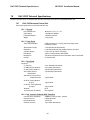
DAC-2202 TECHNICAL SPECIFICATIONS .............................................................................................................................. 18-1
18.1. DAC-2202 ANTENNA CONTROL UNIT ................................................................................................................................................. 18-1
18.1.1. General......................................................................................................................................................................................... 18-1
18.1.2. Front Panel ................................................................................................................................................................................ 18-1
18.1.3. Rear Panel .................................................................................................................................................................................. 18-1
18.1.4. J4A “Antenna” Pedestal M&C Interface ..................................................................................................................... 18-1
18.1.5. J4B “Antenna” Pedestal M&C Interface ..................................................................................................................... 18-2
18.1.6. J3 “M&C” Aux Serial Interface ......................................................................................................................................... 18-2
18.1.7. J2 “NMEA A” Interface ........................................................................................................................................................ 18-2
18.1.8. J2 “NMEA B” Interface......................................................................................................................................................... 18-2
18.1.9. Ethernet ...................................................................................................................................................................................... 18-2
18.1.10. DVB Compliant Tracking Receiver................................................................................................................................. 18-3
18.1.11. L-Band SCPC Narrow Band Tracking Receiver ........................................................................................................ 18-3
18.2. TERMINAL MOUNTING STRIP ................................................................................................................................................................... 18-3
18.2.1. Synchro Interface: ................................................................................................................................................................. 18-3
18.2.2. SBS Interface............................................................................................................................................................................ 18-3
18.2.3. Control Interface ................................................................................................................................................................... 18-4
18.2.4. NMEA Interface ...................................................................................................................................................................... 18-4
18.3. ENVIRONMENTAL CONDITIONS................................................................................................................................................................ 18-4
viii
Table of Contents
3011W-91 Installation Manual
18.4. DAC-2202 AC POWER CONSUMPTION................................................................................................................................................18-4
18.5. CABLES ...........................................................................................................................................................................................................18-5
18.5.1. IF Signal Cables .......................................................................................................................................................................18-5
18.5.2. SBS/Synchro Gyro Compass Interface Cable (Customer Furnished) .........................................................18-5
19. 3011W-91 TECHNICAL SPECIFICATIONS ............................................................................................................................. 19-1
19.1. ANTENNA REFLECTOR/FEED 3011 ..........................................................................................................................................................19-1
19.2. SMW QUAD BAND LNB ...........................................................................................................................................................................19-1
19.3. TX RADIO PACKAGE ( -91 SYSTEMS) .....................................................................................................................................................19-2
19.3.1. OPTIONAL 7550 M&C Interface Unit ........................................................................................................................19-2
19.3.2. OPTIONAL 7552 FSK to USB M&C Interface Unit ...............................................................................................19-2
19.4. BUC POWER SUPPLY...................................................................................................................................................................................19-2
19.5. CO-POL EQUIPMENT ...................................................................................................................................................................................19-2
19.6. MK 2 PEDESTAL CONTROL UNIT (PCU) ...............................................................................................................................................19-3
19.7. MK 2 MOTOR DRIVER ENCLOSURE (MDE) ..........................................................................................................................................19-3
19.8. 400 MHZ BASE & PEDESTAL UNLIMITED AZIMUTH MODEMS (3 CHANNEL) ...............................................................................19-4
19.9. STABILIZED ANTENNA PEDESTAL ASSEMBLY .........................................................................................................................................19-4
19.10. RADOME ASSEMBLY, 40” ...........................................................................................................................................................................19-5
19.11. ADE PEDESTAL POWER REQUIREMENTS: ................................................................................................................................................19-6
19.12. XX10 ENVIRONMENTAL SPECIFICATIONS .............................................................................................................................................19-6
19.12.1. Climatic Conditions ...............................................................................................................................................................19-6
19.12.2. Chemically Active Substances .........................................................................................................................................19-6
19.12.3. Mechanical Conditions ........................................................................................................................................................19-6
19.12.4. Transit Conditions ..................................................................................................................................................................19-6
19.13. BELOW DECKS EQUIPMENT .......................................................................................................................................................................19-6
19.13.1. Antenna Control Unit (ACU)..............................................................................................................................................19-6
19.13.2. Terminal Mounting Strip (TMS) .......................................................................................................................................19-6
19.13.3. Satellite Modem ......................................................................................................................................................................19-6
19.13.4. Router ...........................................................................................................................................................................................19-7
19.14. CABLES ...........................................................................................................................................................................................................19-7
19.14.1. Antenna Control Cable (Provided from ACU to the Base MUX) ....................................................................19-7
19.14.2. Antenna L-Band IF Coax Cables (Customer Furnished).....................................................................................19-7
19.14.3. Multi-conductor Cables (Customer Furnished) ......................................................................................................19-7
20. DRAWINGS ................................................................................................................................................................................................... 20-1
20.1. DAC-2202 ANTENNA CONTROL UNIT DRAWINGS ............................................................................................................................20-1
20.2. 3011W-91 KU-BAND MODEL SPECIFIC DRAWINGS .........................................................................................................................20-1
20.3. 3011 GENERAL DRAWINGS ......................................................................................................................................................................20-1
ix
3011 System Configuration(s)
1.
3011W-91 Installation Manual
3011 System Configuration(s)
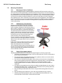
The 3011 Stabilized Antenna system is to be used for Transmit/Receive (TX/RX) satellite communications, it is comprised of two
major groups of equipment. These are the Above Decks Equipment (ADE) and the Below Decks Equipment (BDE). There will
also be interconnecting cables between the ADE & BDE and cables to provide other inputs to the system.
1.1.
System Cables
AC Power & Coaxial cables will be discussed in a separate chapter.
1.2.
Other Inputs to the System
Multi-conductor cables from Ships Gyro Compass, GPS, phone, fax and Computer equipment may also be connected
in the system.
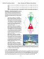
1.3.
Simplified block diagram of a 3011 system
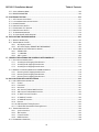
Your 3011 TXRX system consists of two major groups of equipment; an above-decks group and a below-decks group.
Each group is comprised of, but is not limited to, the items listed below. All equipment comprising the Above Decks is
incorporated inside the radome assembly and is integrated into a single operational entity. For inputs, this system
requires only an unobstructed line-of-sight view to the satellite, Gyro Compass input and AC electrical power.
A. Above-Decks Equipment (all shown as the ADE) Group
• Stabilized antenna pedestal
• Antenna Reflector
• Feed Assembly with Cross-Pol LNB
• MAY include Co-Pol LNB
• Ku-Band Solid State Block Up-Converter (BUC)
• Radome Assembly
B. Below-Decks Equipment Group
• Antenna Control Unit
• Terminal Mounting Strip Assembly.
• Base Modem Panel
• Customer Furnished Equipment - Satellite Modem and other below decks equipment required for the
desired communications purposes (including LAN and VOIP equipment).
• Appropriate Coax, Ethernet, and telephone cables
1-1
3011W-91 Installation Manual
1.4.
3011 System Configuration(s)
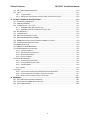
Dual Antenna Configuration
Sometimes, due to very large blockage conditions, you may need to install a dual antenna configuration to provide
uninterrupted services. Two full antenna systems are installed and the ACU control outputs are connected to an
arbitrator switch panel which then is connected to the below decks equipment. NOTE: The RXIF from EACH antenna
MUST be connected to the RF IN (J6) on the rear panel of its respective ACU then RFOUT (J7) is connected to the RXIF
input of the Dual Antenna Arbitrator. This connection scheme is required for ACU “A” to be able to control Antenna
“A” (and ONLY Antenna “A”) AND ACU “B” to be able to control Antenna “B” (and ONLY Antenna “B”).
You will program the blockage zone(s) for each of the two antennas (refer to Setup – Blockage Zones lesson). The
blockage output from the ACU is fed to the Terminal Mounting Strip so that the output of each ACU can be connected
to the arbitrator panel to control it. The blockage output is available on SW2 terminal of the Terminal Mounting Strip
to provide a transistor “short” to ground when the antenna is within a blockage zone programmed into the ACU. When
not blocked the SW2 terminal will be an “open”.
When one antenna is blocked, its blockage output will command the arbitrator panel to switch services to the modem
from that antenna to the other antenna. The arbitrator panel provides a logic latch to prevent excess switching when
the ship heading is yawing, therefore, causing if the antenna to be repeatedly blocked – unblocked – blocked.
1-2
3011 System Configuration(s)
1.5.
3011W-91 Installation Manual
Dual Antenna Arbitrator
The Dual Antenna Arbitrator panel can pass LNB voltages (and handle 250-400 ma of current) and the RXIF signals on
the RX connections. TXIF, Reference and BUC supply voltage can be passed through this arbitrator panel to the
antenna, but it is not recommended that BUC power be supplied through the dual channel rotary joint of the antenna
(a BUC power supply is provided on all Series 09 Antenna Pedestals).
The blockage (SW2) output, GPS output and Modem lock input from the two terminal mounting strips (antenna “A”
and antenna “B”) are wired through the arbitrator panel to the satellite modem. When antenna “A” is blocked, the
arbitrator PCB will toggle the coax switches so that antenna “B” provides signal to the BDE distribution (multi-switch or
modem). When antenna “A” is no longer blocked the arbitrator will do nothing (because it is a latch circuit). When
antenna “B” is blocked the panel will switch so that antenna “A” is again providing signal the BDE distribution.
To provide a seamless switching transition, refer to the arbitrator installation instructions to balance the TX & RX signal
levels between the two antennas.
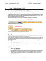
1.6.
Open Antenna-Modem Interface Protocol (OpenAMIP™) Specification:
1.6.1.
Overview:
OpenAMIP, an ASCII message based protocol invented and Trademarked by iDirect is a specification for the
interchange of information between an antenna controller and a satellite modem. This protocol allows the
satellite modem to command the ACU (via TCP port 2002) to seek a particular satellite as well as allowing
exchange of information necessary to permit the modem to initiate and maintain communication via the
antenna and the satellite. In general, OpenAMIP is not intended for any purpose except to permit a modem
and the ACU to perform synchronized automatic beam switching. It is NOT a status logging system or a
diagnostic system. In addition, OpenAMIP is intend for a typical installation whereby a specific satellite
modem and Antenna system are properly configured to work together. The protocol does not make specific
provisions for auto-discovery or parameter negotiation. It is still the responsibility of the installer to assure
1-3
3011W-91 Installation Manual
3011 System Configuration(s)
the parameters of both the satellite modem (proper option files) and the ACU/PCU (setup parameters) are
actually compatible for the intended satellite(s).
1.6.2.
Interface requirements:
1.6.2.1.
Hardware
Sea Tel Antenna Control Units Model DAC2202 or DAC2302.
Any Satellite modem manufacturer that is compatible with OpenAMIP
CAT5 Patch cable
1.6.2.2.
Software
Sea Tel model DAC2202:
ACU software version 6.06 or greater
CommIF module software version 1.10f or greater
Sea Tel model DAC2302:
ACU software version 7.06 or greater
CommIF module software version 1.10f or greater
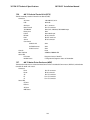
1.6.3.
Utilized OpenAMIP Commands:
1.6.3.1.
Command
S f1 f2 f3
P c1 c2
H f1 f2
B f1 f2
F
Ai
L b1 b2
Wi
I s1 s2
Description
Satellite Longitude, 3 parameters:
Degrees E/W (-value equals West), Latitude Variance (Inclined
Orbit), Sat Skew Offset
Polarization, 2 parameters:
H,V,L,, or R
Tracking Frequency: 2 Parameters:
Center Frequency and Bandwidth in MHz
Down Conversion Offset: 2 parameters:
LNB (Receive) Local Oscillator and BUC (TX) L.O.
Find,
Target satellite using existing S, P,R, and H Parameters
Set keep alive in seconds (0 = off)
Modem Lock and free to transmit. 2 parameters:
b1 indicates Rx lock and b2 (not utilized) enables/disables Tx
Mute to BUC
GPS Update:
Sets GPS Update period in seconds (0 = Off)
Set modem vendor (s1) and device (s2) 2 parameters:
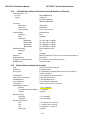
1.6.3.2.
Command
ai
i s1 s2
s b1 b2
w b1 f1 f2 t1
Antenna Commands:
Example
“S -20.1 1.0 3.5”
“P L R”
“H 1100.500 0.256”
“B 10750”
“A 5”
“L 1 1”
“W 300”
“I iDirect 5100”
Modem Commands:
Description
Set keep alive in seconds (0 = off)
Set Antenna Vendor (s1) and device (s2) 2 parameters:
Antenna Status: 2 parameters:
b1 is functional status and b2 is Tx allowed
Set GPS Position: 4 parameters:
b1 is validity flag, f1 is latitude, f2 is longitude, and t1 is
timestamp
1-4
Example
“a 5”
“i Sea Tel DAC-2202”
“s 1 1”
“w 1 38.222 122.123
0”
Site Survey
2.
3011W-91 Installation Manual
Site Survey
The objective of the Site survey is to find the best place to mount the antenna & the below decks equipment, the length and
routing of the cables and any other items or materials that are required to install the system and identify any other issues that
must be resolved before or during the installation. For Naval Engineering level information on this subject, please refer
to Antenna Installation Guideline – Site Arrangement, document number 130040_A available on the Sea Tel
Dealer Support Site.
2.1.
Site Selection Aboard Ship
The radome assembly should be installed at a location aboard ship where:
•
The antenna has a clear line-of-sight to view as much of the sky (horizon to zenith at all bearings) as is
practical.
•
X-Band (3cm) Navigational Radars:
•
•
The ADE should be mounted more than 0.6 meters/2 feet from 2kW (24 km) radars
•
The ADE should be mounted more than 2 meters/8 feet from 10kW (72 km) radars
•
The ADE should be mounted more than 4 meters/12 feet from 160kW (250km) radars
S-Band (10cm) Navigational Radars:
•
If the ADE is/has C-Band it should be mounted more than 4 meters/12 feet from the S-band Radar.
•
The ADE should not be mounted on the same plane as the ship's Radar, so that it is not directly in the Radar
beam path.
•
The ADE should be mounted more than 2.5 meters/8 feet from any high power MF/HF antennas (<400W).
•
The ADE should be mounted more than 4 meters/12 feet from any high power MF/HF antennas (1000W).
•
The ADE should also be mounted more than 4 meters/12 feet from any short range (VHF/UHF) antennae.
•
The ADE should be mounted more than 2.5 meters/8 feet away from any L-band satellite antenna.
•
The ADE should be mounted more than 3 meters/10 feet away from any magnetic compass installations.
•
The ADE should be mounted more than 2.5 meters/8 feet away from any GPS receiver antennae.
•
Another consideration for any satellite antenna mounting is multi-path signals (reflection of the satellite
signal off of nearby surfaces arriving out of phase with the direct signal from the satellite) to the antenna.
This is particularly a problem for the onboard GPS, and/or the GPS based Satellite Compass.
•
The Above Decks Equipment (ADE) and the Below Decks Equipment (BDE) should be positioned as close to
one another as possible. This is necessary to reduce the losses associated with long cable runs.
•
This mounting platform must also be robust enough to withstand the forces exerted by full rated wind load
on the radome.
•
The mounting location is robust enough that it will not flex or sway in ships motion and be sufficiently well
re-enforced to prevent flex and vibration forces from being exerted on the antenna and radome.
•
If the radome is to be mounted on a raised pedestal, it MUST have adequate size, wall thickness and gussets
to prevent flexing or swaying in ships motion. In simple terms it must be robust.
If these conditions cannot be entirely satisfied, the site selection will inevitably be a “best” compromise between the
various considerations.
2.2.
Antenna Shadowing (Blockage) and RF Interference
At the transmission frequencies of C and Ku band satellite antenna systems, any substantial structures in the way of
the beam path will cause significant degradation of the signal. Care should be taken to locate the ADE so that the ADE
has direct line-of-sight with the satellite without any structures in the beam path through the full 360 degree ships
turn. Wire rope stays, lifelines, small diameter handrails and other accessories may pass through the beam path in
limited numbers; however, even these relatively insignificant shadows can produce measurable signal loss at these
frequencies.
2-1
3011W-91 Installation Manual
2.3.
Site Survey
Mounting Foundation
2.3.1.
Mounting on Deck or Deckhouse
While mounting the ADE on a mast is a common solution to elevate the ADE far enough above the various
obstructions which create signal blockages, sometimes the best mounting position is on a deck or deckhouse
top. These installations are inherently stiffer than a mast installation, if for no other reason than the design of
the deck/deckhouse structure is prescribed by the ship’s classification society. In the deck/deckhouse design
rules, the minimum plating and stiffener guidelines are chosen to preclude high local vibration amplitudes.
Most installations onto a deck or deckhouse structure will require a mounting pedestal to raise the ADE above
the deck for radome hatch access and to allow the full range of elevation (see ADE mounting considerations
above). Some care must be taken to ensure the mounting pedestal is properly aligned with the stiffeners
under the deck plating.
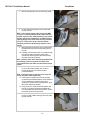
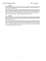
2.3.2.
ADE Mounting Considerations
Mounting the radome directly on the deck, or platform
prevents access to the hatch in the base of the radome
unless an opening is designed into the mounting surface to
allow such entry. If there is no access to the hatch the only
way to service the antenna is to remove the radome top.
Two people are required to take the top off of the radome
without cracking or losing control of it, but even with two
people a gust of wind may cause them to lose control and
the radome top may be catastrophically damaged (see
repair information in the radome specifications).
If access to the hatch cannot be provided in the mounting
surface, provide a short ADE support pedestal to mount the
ADE on which is tall enough to allow access into the radome
via the hatch.
Ladder rungs must be provided on all mounting stanchions
greater than 3-4 feet tall to allow footing for personnel
safety when entering the hatch of the radome.
The recommended cable passage in the 50, 60 and 66 inch
radomes is through the bottom center of the radome base,
down through the ADE support pedestal, through the deck
and into the interior of the ship.
2.3.3.
Sizing of the support pedestal
The following should be taken into account when choosing the height of a mounting support stand:
1. The height of the pedestal should be kept as short as possible, taking into account recommendations
given in other Sea Tel Guidelines.
2. The minimum height of the pedestal above a flat deck or platform to allow access into the radome
for maintenance should be 0.6 meters (24 inches).
3. The connection of the ADE mounting plate to the stanchion and the connection of the pedestal to
the ship should be properly braced with triangular gussets (see graphic above). Care should be taken
to align the pedestal gussets to the ship’s stiffeners as much as possible. Doublers or other
reinforcing plates should be considered to distribute the forces when under-deck stiffeners are
inadequate.
4. The diameter of the pedestal stanchion shall not be smaller than 100 millimeters (4 inches). Where
the ADE base diameter exceeds 1.5 meters (60 inches), additional stanchions (quantity greater than
3) should be placed rather than a single large stanchion.
5. Shear and bending should be taken into account in sizing the ADE mounting plate and associated
gussets.
6. Shear and bending must be taken into account when sizing the pedestal to ship connection.
7. All welding should be full penetration welds –V-groove welds with additional fillet welds – with
throats equivalent to the thickness of the thinnest base material.
2-2
Site Survey
3011W-91 Installation Manual
8.
9.
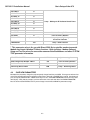
2.4.
For an ADE mounted greater than 0.6 meters (24 inches) above the ship’s structure, at least one (1)
foot rung should be added. Additional rungs should be added for every 0.3 meter (12 inches) of
pedestal height above the ship’s structure.
For an ADE mounted greater than 3 meters (9 feet) above the ship’s structure, a fully enclosing cage
should be included in way of the access ladder, starting 2.3 meters (7 feet) above the ship’s
structure.
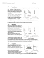
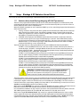
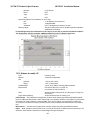
Mounting Height
The higher up you mount the antenna above the pivot point of the ship the higher the tangential acceleration (gforce) exerted on the antenna will be (see chart below).
When the g-force exerted on the antenna is light, antenna stabilization and overall performance will not be affected.
If the g-force exerted on the antenna is high enough (> 1 G), antenna stabilization and overall performance will be
affected.
If the g-force exerted on the antenna is excessive (1-2 Gs), the antenna will not maintain stabilization and may even
be physically damaged by the g-force.
2.5.
Mast Configurations
Sea Tel recommends the ADE be mounted on the ship in a location which has both a clear line-of-sight to the target
satellites in all potential azimuth/elevation ranges and sufficient support against vibration excitement. If possible,
mounting the ADE pedestal directly to ship deckhouse structures or other box stiffened structures is preferred.
However, in many cases, this imposes limits on the clear line-of-sight the antenna system has.
Often the solution for providing the full azimuth/elevation range the antenna needs is to mount the ADE on the ship’s
mast. Unfortunately, masts do not consider equipment masses in design and often have harmonic frequencies of their
own.
There are many designs of masts used on ships – masts are nearly as unique in design as the ship is – but the designs
often fall into just a few categories. These categories can be addressed in terms of typical responses and problems
with regards to vibration and mounting of ADE. The most common categories of masts are:
2-3
3011W-91 Installation Manual
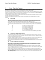
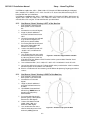
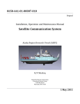
2.5.1.
Site Survey
Vertical Masts
Vertical masts are a very ancient and common mast design. In essence, it is the mast derived from the sailing
mast, adapted for mounting the ever-increasing array of antennae ships need to communicate with the
world. This drawing of a Vertical mast shows
preferred mounting of the ADE center-line above
the plane of the radar, or as an alternate with the
ADE mounted below the plane of the radar signal,
as reasonably good installations of a satellite
antenna ADE.
Vertical masts are most commonly still found on
cargo ships – they are simple, inelegant and
functional. They are also fairly stiff against
torsional reaction and lateral vibrations, as long as
the ADE is mounted on a stiff pedestal near the
vertical centerline of the mast. If centerline
mounting is impractical or otherwise prohibited,
the mast platform the ADE is mounted on should be checked for torsional vibration about the centerline of
the mast and the orthogonal centerline of the platform.
If the estimated natural frequency of the mast or platform is less than 35 Hertz, the mast or platform should
be stiffened by the addition of deeper gussets under the platform or behind the mast.
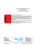
2.5.2.
Raked Masts
Raked masts are found on vessels where the style
or appearance of the entire vessel is important.
Again, the inclined mast is a direct descendant from
the masts of sailing ships – as ship owners wanted
their vessels to look more unique and less
utilitarian, they ‘raked’ the masts aft to make the
vessel appear capable of speed. This drawing
shows a raked mast, again with the preferred ADE
mounting above the radar and alternate with the
ADE below the radar.
Raked masts pose special problems in both
evaluating the mast for stiffness and mounting of
antennae. As can be seen in the drawing all
antennae must be mounted on platforms or other
horizontal structures in order to maintain the
vertical orientation of the antenna centerline. This
implies a secondary member which has a different
natural frequency than the raked mast natural frequency. In order to reduce the mass of these platforms,
they tend to be less stiff than the main box structure of the raked mast. Thus, they will have lower natural
frequencies than the raked mast itself. Unfortunately, the vibratory forces will act through the stiff structure
of the raked mast and excite these lighter platforms, to the detriment of the antenna.
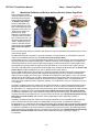
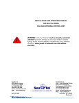
2.5.3.
Girder Masts
Girder masts are large platforms atop a pair of
columns. Just like girder constructions in buildings,
they are relatively stiff athwart ship – in their
primary axis – but less stiff longitudinally and
torsionally. An example of a girder mast is shown in
this drawing, with the preferred ADE mounting
outboard and above the radar directly on one of the
columns and alternate with the ADE centered on
the girder above the plane of the radar.
The greatest weakness of girder masts is in torsion –
where the girder beam twists about its vertical
centerline axis. As with all mast designs discussed so far, mounting the antenna in line with the vertical
2-4
Site Survey
3011W-91 Installation Manual
support structure will reduce the vibration tendencies. Mounting the antenna directly above the girder
columns provides ample support to the antenna pedestal and locates the antenna weight where it will
influence the natural frequency of the mast the least.
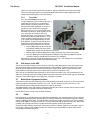
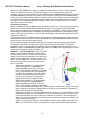
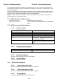
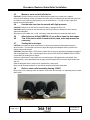
2.5.4.
Truss Mast
Truss masts are a variant on the girder mast
concept. Rather than a pair of columns supporting a
girder beam, the construction is a framework of
tubular members supporting a platform on which
the antennae and other equipment is mounted. A
typical truss mast is shown in this photograph.
Like a girder mast, truss masts are especially stiff in
the athwart ship direction. Unlike a girder mast, the
truss can be made to be nearly as stiff in the
longitudinal direction. Truss masts are particularly
difficult to estimate the natural frequency – since a
correct modeling includes both the truss structure
of the supports and the plate/diaphragm structure
of the platform. In general, though, the following
guidelines apply when determining the adequate
support for mounting an antenna on a truss mast:
1. Antenna ADE pedestal gussets should align
with platform stiffeners which are at least
200 millimeters in depth and 10 millimeters in thickness.
2. When possible, the antenna ADE pedestal column should align with a vertical truss support.
3. For every 100 Kilograms of ADE weight over 250 Kilograms, the depth of the platform stiffeners
should be increased by 50 millimeters and thickness by 2 millimeters.
Sea Tel does not have a recommended arrangement for a truss mast – the variability of truss mast designs
means that each installation needs to be evaluated separately.
2.6.
Safe Access to the ADE
Safe access to the ADE should be provided. Provisions of the ship’s Safety Management System with regard to men
aloft should be reviewed and agreed with all personnel prior to the installation. Installations greater than 3 meters
above the deck (or where the access starts at a deck less than 1 meter in width) without cages around the access
ladder shall be provided with means to latch a safety harness to a fixed horizontal bar or ring.
The access hatch for the ADE shall be oriented aft, or inboard, when practicable. In any case, the orientation of the
ADE access hatch shall comply with the SMS guidelines onboard the ship. Nets and other safety rigging under the ADE
during servicing should be rigged to catch falling tools, components or fasteners.
2.7.
Below Decks Equipment Location
The Antenna Control Unit, Terminal Mounting Strip and Base Modem Panel are all standard 19” rack mount, therefore,
preferred installation of these items would be in such a rack. The ACU mounts from the front of the rack. The
Terminal Mounting Strip and Base Modem Panel mount on the rear of the rack.
The Satellite Modem, router, VIOP adapter(s), telephone equipment, fax machine, computers and any other associated
equipment should also be properly mounted for shipboard use.
Plans to allow access to the rear of the should be considered.
2.8.
Cables
During the site survey, walk the path that the cables will be installed along. Pay particular attention to how cables will
be installed all along the path, what obstacles will have to have be routed around, difficulties that will be encountered
and the overall length of the cables. The ADE should be installed using good electrical practice. Sea Tel recommends
referring to IEC 60092-352 for specific guidance in choosing cables and installing cables onboard a ship. Within these
guidelines, Sea Tel will provide some very general information regarding the electrical installation.
In general, all cables shall be protected from chaffing and secured to a cableway. Cable runs on open deck or down a
mast shall be in metal conduit suitable for marine use. Cables passing through bulkheads or decks shall be routed
through approved weather tight glands.
2-5
3011W-91 Installation Manual
2.8.1.
Site Survey
ADE/BDE Coaxial Cables
The first concern about the coaxial cables installed between the ADE & BDE is length. This length is used to
determine the loss of the various possible coax, Heliax or fiber-optic cables that might be used. You should
always provide the lowest loss cables to provide the strongest signal level into the satellite modem.
Signal cable shall be continuous from the connection within the ADE radome, through the structure of the
ship to the BDE. Splices, adapters or dummy connections will degrade the signal level and are discouraged.
Be careful of sharp bends that kink and damage the cable. Use a proper tubing bender for Heliax bends.
Penetrations in watertight bulkheads are very expensive, single cable, welded penetrations that must be
pressure tested.
Always use good quality connectors that are designed to fit properly on the cables you are using. Poor
quality connectors have higher loss, can allow noise into the cable , are easily damaged or fail prematurely.
In as much as is possible, don’t lay the coaxes on power cables. Try to have some separation from Inmarsat &
GPS cables that are also passing L-band frequencies or Radar cables that may inject pulse repetition noise –as
error bits - into your cables.
2.8.2.
Antenna Power Cable
Be cautious of length of the run, for voltage loss issues, and assure that the gauge of the wires is adequate for
the current that is expected to be drawn (plus margin) . Antenna power is not required to be from a UPS
(same one that supplies power to the below decks equipment), but it is recommended.
2.8.3.
Air Conditioner Power Cable
If your system includes a marine air conditioner (available with the 81 inch radome ONLY), run an AC power
cable to it from a breaker, preferably from a different phase of the electrical system than supplies power to
the ADE & BDE. Be EXTREMELY cautious of length of the run for voltage loss and gauge of the wires for the
current that is expected to be drawn.
2.8.4.
ACU Power Cable/outlet
The AC power for the ACU and other below decks equipment is not required to be from a UPS (same one that
supplies power to the ADE), but it is recommended.
2.8.5.
Gyro Compass Cable
Use good quality shielded cable (twisted pairs, individually foil wrapped, outer foil with braid overall is best)
You only need 2-wire for NMEA signal, 4-wire for Step-By-Step and 5-wire for Synchro … always use shielded
cable. Be cautious of length and gauge of the run for voltage loss issues.
2.9.
Grounding
All metal parts of the ADE shall be grounded to bare metal at the mounting pedestal. Grounding straps from the base
of the ADE to a dedicated lug on the mounting pedestal are preferred, but grounding may also be accomplished by
exposing bare metal under all mounting bolts prior to final tightening. Preservation of the bare metal should be done
to prevent loss of ground.
Grounding should be ensured throughout the entire mounting to the hull. While it is presumed the deckhouse is
permanently bonded and grounded to the hull, in cases where the deckhouse and hull are of different materials a
check of an independent ground bonding strap should be made. Masts should be confirmed to be grounded to the
deckhouse or hull.
2-6
Installation
3.
3011W-91 Installation Manual
Installation
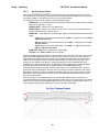
Your antenna pedestal comes completely assembled in its radome. This section contains instructions for unpacking, final
assembly and installation of the equipment. It is highly recommended that installation of the system be performed by trained
technicians.
Your antenna may have been ordered in any one of a variety of different diameter radomes. The installation instructions for
most common radome sizes for your system are below.
3.1.
Unpacking and Inspection
Exercise caution when unpacking the equipment.
1. Unpack the crates. Carefully inspect the radome surface for evidence of shipping damage.
2. Unpack all the boxes.
3. Inspect everything to assure that all materials have been received and are in good condition.
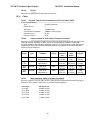
3.2.
Assembly Notes and Warnings
NOTE: All nuts and bolts should be assembled using the appropriate Loctite thread-locker
product number for the thread size of the hardware.
Loctite # Description
222
Low strength for small fasteners.
242
Medium strength
638
High strength for Motor Shafts & Sprockets.
2760
Permanent strength for up to 1” diameter fasteners.
290
Wicking, High strength for fasteners which are already
assembled.
WARNING: Assure that all nut & bolt assemblies are tightened according to the
tightening torque values listed below:
SAE Bolt Size
Inch Pounds
Metric Bolt Size
Kg-cm
1/4-20
75
M6
75.3
5/l6-18
132
M8
150
3/8-16
236
M10
270
1/2-13
517
M12
430
WARNING: Hoisting with other than a webbed four-part sling may result in catastrophic
crushing of the radome. Refer to the specifications and drawings for the fully assembled
weight of your model Antenna/Radome and assure that equipment used to lift/hoist this
system is rated accordingly.
CAUTION: The antenna/radome assembly is very light for its size and is subject to large
swaying motions if hoisted under windy conditions. Always ensure that tag lines, attached
to the radome base frame, are attended while the antenna assembly is being hoisted to its
assigned location aboard ship.
3-1
3011W-91 Installation Manual
3.3.
Installation
Installing the ADE
The antenna pedestal is shipped completely assembled in its radome. Please refer to the entire Site Survey chapter of
this manual.
Base Hatch Access - Mounting the radome directly on the deck, or
platform prevents access to the hatch in the base of the radome unless an
opening is designed into the mounting surface to allow such entry. If there is
no access to the hatch the only way to service the antenna is to remove the
radome top. Two people are required to take the top off of the radome
without cracking or losing control of it, but even with two people a gust of
wind may cause them to lose control and the radome top may be
catastrophically damaged (see repair information in the radome
specifications) or lost.
If access to the hatch cannot be provided in the mounting surface, provide a
short ADE mounting stanchion to mount the ADE on which is tall enough to
allow access into the radome via the hatch.
Ladder rungs must be provided on all mounting stanchions greater than 3-4
feet tall to allow footing for personnel safety when entering the hatch of the
radome.
Cable Passage - The radome base is designed with a bottom center cable
passage and Roxtec® Multidiameter® blocks for cable strain relief. The
recommended cable passage in the 50, 60 and 66 inch radomes is through the
bottom center of the radome base, down through the ADE mounting
stanchion, through the deck and into the interior of the ship.
Bottom center cable passage is recommended, however, a strain relief kit is provided with the system if off-center
cable entry is required. Note: Strain relief installation procedure, provided in the Drawings chapter, MUST
be followed to assure that the cored holes are properly sealed to prevent moisture absorption and delamination of the radome base.
3.3.1.
Prepare the 50”, 60”, 66” or 76” Radome Assembly
1.
2.
3.
Remove the side walls of the Radome crate.
Lift the pallet using a forklift and/or jacks.
From the under side of the pallet, remove the
4 shipping bolts which attach the ADE to its’
pallet. Discard this shipping hardware.
4.
Remove four equally spaced bolts around the
radome flange. Save these nuts and bolts to
be re-installed later.
Install four lifting eyebolts in the vacant holes
in the flange of the radome.. (Hardware
provided in the radome installation kit). Keep
the original perimeter bolt hardware to be reinstalled after the ADE has been installed.
5.
3-2
Installation
3011W-91 Installation Manual
6.
7.
3.3.2.
Attach shackles and four part web lifting sling
arrangement to the eyebolts.
Attach a suitable length tagline to one of the
eyebolts.
Installing the 50, 60 or 66” Radome Assembly
The antenna pedestal is shipped completely assembled in its radome.
1.
2.
3.
4.
5.
6.
Man the tag line(s).
Hoist the antenna assembly off the shipping pallet,
by means of a suitably sized crane or derrick, to allow
access to bottom of radome assembly.
Open the hatch by pressing the round release button
in the center of the black latches and gently push the
hatch up into the radome. Place the hatch door (gel
coat surface up) inside the radome on the far side of
the antenna pedestal.
Inspect the pedestal assembly and reflector for signs
of shipping damage.
Peel the paper off of the mounting pad (provided in
the radome installation kit) to expose the sticky side
of the pad, align it to the mounting holes and press it
in place on the underside of the radome base.
Using Loctite 271, install the 4 mounting bolts
(provided in radome mounting kit) into the radome
base.
3-3
3011W-91 Installation Manual
7.
Installation
Remove the hardware in the cable mounting frame.
8.
Lift the cable mounting frame out from the cable
passage channel.
NOTE: If the bottom center cable passage will NOT
be used, it is recommended that the strain reliefs be
installed in place of this cable mounting frame. Other
locations around the radome base are MUCH thicker,
requiring longer strain reliefs than the ones provided
by Sea Tel. Refer to the strain relief installation
procedure provided in the Drawings chapter of this
manual.
9. Man the tag line and have the crane continue lifting
the ADE up and hover above the mounting site on
the ship.
10. Carefully route AC Power and IF coax cables through
the cable passage in the bottom center of the
radome base and through the cable channel under
the lower base plate of antenna.
NOTE: Suitable strain relief should be provided below
the mounting surface to prevent the cables from
being kinked where the cables exit the bottom of the
radome.
11. Allow enough service loop to terminate these cables
to the circuit breaker assembly and connector
bracket respectively (see cable termination
information below).
HINT: It may be easier to connect, or tie-wrap, the
coaxes and power cable temporarily.
12. Lower radome assembly into the mounting holes,
positioned with the BOW reference of the radome as
close to parallel with centerline of the ship as
possible (any variation from actual alignment can be
electrically calibrated if needed).
13. Using Loctite 271, install the 4 fender washers and
hex nuts (provided in the radome installation kit),
from the underside of the mounting surface, to affix
the radome to the mounting surface. .
14. Remove the clamp bar and Roxtec® Multidiameter®
blocks from their cable mounting frame in the cable
passage channel.
3-4
Installation
3011W-91 Installation Manual
15. Remove the rubber bar from the top of the Roxtec®
Multidiameter® blocks.
16. Remove the Roxtec® Multidiameter® blocks from
the cable mounting frame.
17. Pass the coaxes and power cable through the cable
mounting frame.
HINT: Again, It may be easier to connect, or tie-wrap,
the coaxes and power cable temporarily.
18. Re-install the cable mounting frame onto cable
passage channel using the four screws and flat
washers that were removed in step 7 above. .
19. Peel layers out of the upper and lower Roxtec®
Multidiameter® blocks to provide an opening in the
block that is just smaller than the outer diameter of
the cable that will pass through it. When
compressed the block should provide clamping force
on the cable and prevent it from moving in the block.
20. Two cables may be passed through each of the
Roxtec® Multidiameter® CM-20w40 blocks
provided.
21. If cables larger than 1.65cm/0.65in outer diameter
will be used, larger single-cable Roxtec®
Multidiameter CM-40 10-32 blocks are available to
allow three cables of up to3.25cm/1.28in diameter
to be used. The rubber bar and the three doublecable Roxtec® Multidiameter blocks will be
replaced by the three larger Roxtec®
Multidiameter blocks.
3-5
3011W-91 Installation Manual
Installation
HINT: It may be helpful to put the clamp bar and
rubber bar in place (held loosely by one screw) to
hold some of the Roxtec® Multidiameter blocks in
place while you complete the others.
22. Re-install the clamp bar using the hardware removed
in step 14 above.
3.4.
Removing the Shipping/Stow Restraints PRIOR to Power-Up
The order in which the restraints are removed is not critical.
CAUTION: There are three shipping/Stow restraints on this antenna pedestal
that MUST be removed, before energizing the antenna, for normal operation.
3.4.1.
1.
Removing the AZ Shipping/Stow Restraint
The AZ Shipping/Stow restraint is formed by a
pin that is lowered into a channel in a stowage
block on the upper plate of the pedestal (as
shown).
Stow Plunger Handle
Stow pin
Stow Block
3-6
Installation
3011W-91 Installation Manual
2.
To un-restrain azimuth rotation of the
antenna simply lift the spring loaded plunger
handle and rotate it 90 degrees (CW or CCW)
to its retracted/locked position (assure that
the horizontal pin locks into the grooves in
the top collar).
Un-Stowed Position
Stowed Position
3.
4.
Verify that the stow pin is retracted up and
out of the stow block channel.
Verify that the antenna rotates freely and
easily a full 360 degrees CW & CCW.
3.4.2.
1.
2.
Removing the EL Shipping/Stow Restraint
The EL Shipping/Stow restraint is formed by a
Stow pin-bolt mounted through a bracket and
is engaged into a hole in the elevation pan
when the dish is up at zenith (90 degrees
elevation).
In the stowed position the hardware from
right to left is Stow pin-bolt head, washer,
bracket, washer, hex nut, hex nut so that the
pin section of the Stow pin-bolt is inserted
into the hole in the elevation pan.
Pin inserted into Elevation Pan
2 Hex Nuts
Bracket
EL Stow Pin-Bolt head
3-7
3011W-91 Installation Manual
3.
4.
5.
6.
7.
8.
9.
3.4.3.
1.
Installation
To un-restrain the elevation axis of the
antenna, unthread the two hex nuts. Remove
the hex nuts and washer from the stow pinbolt.
Remove the stow pin-bolt from the bracket.
Remove the washer from the stow pin-bolt
and thread one of the 2 hex nuts onto the
bolt and tighten.
Put one of the washers onto the stow pin-bolt
and insert it into the bracket toward the
elevation pan.
Put the other washer, and then the other hex
nut, onto the bolt.
Tighten the hex nut to prevent the hardware
from loosening while in the un-stowed
configuration.
Verify that the antenna rotates freely and
easily through its full elevation range of
motion.
Removing the CL Shipping/Stow Restraint
The CL Shipping/Stow restraint is formed by a
red locking bar with adjustable bumpers at
each end of the bar. This mechanism is
placed under the cross-level beam to lock it in
place.
Cross-Level Beam
CL Shipping/Stow bar
Adjustable CL Locking Bumpers (only one end shown)
3-8
Installation
3011W-91 Installation Manual
2.
To un-restrain the cross-level axis of the
antenna use a 7/16“ open end wrench to
loosen the nut on the top side of the locking
bar (either end of the bar).
3.
Remove the bottom nut off of that adjustable
bumper.
Remove the adjustable bumper from the
locking bar.
Extract the locking bar from the underside of
the cross-level beam and retain these parts for
later re-use if it becomes necessary to stow
the antenna.
Verify that the antenna rotates (tilts left &
right from level) freely and easily a through its
full cross-level range of motion.
4.
5.
6.
3.5.
Cable Installation
3.5.1.
Shipboard Cable Installation
CAUTION: Rough handling, tight bending, kinking, crushing and other careless
handling of the cables and their connectors can cause severe damage.
The cables must be routed from the above-decks equipment mounting location through the deck and
through various ship spaces to the vicinity of the below-decks equipment. When pulling the cables in place,
avoid sharp bends, kinking, and the use of excessive force. After placement, seal the deck penetration glands
and tie the cables securely in place all along the cable run(s).
3.6.
Installing the Below Decks Equipment.
Installing the Antenna Control Unit, Base Multiplexer Panel and the Terminal Mounting Strip.
3.6.1.
General Cautions & Warnings
CAUTION - Electrical Shock Potentials exist on the Gyro Compass output
lines. Assure that the Gyro Compass output is turned OFF when handling and
connecting wiring to the Terminal Mounting Strip.
CAUTION - Allow only an authorized dealer to install or service the your Sea Tel
System components. Unauthorized installation or service can be dangerous and may
invalidate the warranty.
3.6.2.
Preparing BDE Location
Prepare the Rack (or other location) for the ACU, Terminal Mounting Strip and base multiplexer panel.
Prepare the mounting locations for the other Below Decks Equipment throughout ship.
3-9
3011W-91 Installation Manual
3.6.3.
1.
2.
3.
4.
3.7.
Installation
Installing the Below Deck Equipment
Install the ACU in the front of the standard 19” equipment rack or other suitable location. The DAC2202 ACU is one rack unit high.
Install the Terminal Mounting Strip on the rear of the 19” equipment rack or other suitable location
that is within 6 feet of the rear panel connections of the ACU. It also is one rack unit height.
Install the Base Multiplexer Panel on the rear of the 19” equipment rack or other suitable location
that is within 6 feet of the rear panel connections of the ACU. It is four rack unit height.
Install your Satellite Modem, Router, VOIP adapters, Telephone equipment, Fax machine, Computers
and any other below decks equipment that are part of your installation.
Connecting the Below Decks Equipment
Connect this equipment as shown in the System Block Diagram.
3.7.1.
Connecting the ADE AC Power Cable
Connect the AC Power cable that supplies power to the ADE to a suitably rated breaker or UPS.
3.7.2.
Connecting the BDE AC Power Cables
Connect the AC Power cables that supply power to the Below Decks Equipment (ACU, Satellite Modem,
phone, fax, computer and all other equipment) to an outlet strip fed from a suitably rated breaker or UPS.
3.7.3.
1.
2.
3.7.4.
Connecting the ADE IF Coaxes
Attach the TXIF coax from the antenna to the TX Connector on the Base Multiplexer Panel.
Attach the RXIF coax from the antenna to the RX Connector on the Base Multiplexer Panel.
Connect the Modem TXIF Coax
Connect the TXIF coax from the Base Multiplexer Panel to the Satellite Modem TX Output.
3.7.5.
Antenna Control Unit Connections
Figure 1-1 Rear Panel DAC-2202 ACU
3.7.5.1.
Antenna Control Serial Cable
Connected the Antenna Control Serial Cable from the Base Multiplexer to J4A on the DAC-2202.
3.7.5.2.
ACU to Terminal Mounting Strip Connections
Connect the TMS to the ACU.
1. Connect the 25 pin ribbon cable from the Terminal Mounting Strip to J1 “Ships Gyro” DB25
on the rear panel of the ACU.
2. Connect the 9 pin ribbon cable (or NMEA serial cable) from the Terminal Mounting Strip to
J2 “NMEA” DB9 on the rear panel of the ACU
3.7.5.3.
RXIF Signal Input to the ACU
Connect the RXIF cable from the Base Multiplexer to the J6 “RF IN” connector on the rear of the
ACU. This input provides satellite signal to the tracking receiver inside the Antenna Control Unit.
3-10
Installation
3011W-91 Installation Manual
3.7.5.4.
RXIF to the Satellite Modem
Connect J7 “RF OUT” on the rear panel of the ACU to the RX Input connector on the Satellite
Modem. The RX signal level of the J7 output of the ACU is approximately unity with J6 input due to
an in internal amplifier.
3.7.5.5.
Ethernet Connection to the ACU
The Ethernet connection can be used to Monitor & Control the antenna through Antenna Control
Unit via the internal web pages, by use of DacRemP IP or via an Ethernet connection through a
router/switch/hub to an Open AMIP compatible satellite modem. Use an Ethernet patch cable to
make your desired connection to the Ethernet connector on the rear panel of the ACU.
3.7.5.6.
M&C Connection to the ACU
If you wish to use a computer to Monitor & Control the antenna through the Antenna Control Unit
there are two possible connections that can be made. One choice is a serial connection from J3
“M&C” connector on the rear panel of the ACU to a COM port on the computer using a serial
extension cable. Another choice is to connect the “ETHERNET” connector on the rear panel of the
ACU to a LAN connection on the computer or hub using an Ethernet crossover cable.
3.7.6.
Radio Control Serial Cable
133BU
If desired, connected the Radio Control Serial Cable from the Base Multiplexer to the COM Port of a
Customer Furnished Computer.
3.7.7.
Terminal Mounting Strip (TMS) Connections
Connect the Ships Gyro Compass input to the appropriate screw terminals on this strip. The satellite modem
must also be connected to provide compliance with FCC Order 04-286 and WRC-03 Resolution 902.
There are several functional connections that may be made on the TMS connectors. Although you may not
need to make all of these connections, they are listed here for clarification during the installation process.
Connect the 9 pin ribbon cable from this PCB to J2 “NMEA” DB9 on the rear panel of the ACU. Connect the
25 pin ribbon cable from this PCB to J1 “Ship Gyro” DB25 on the rear panel of the ACU.
CAUTION - Electrical Shock Potentials exist on the Gyro Compass output
lines. Assure that the Gyro Compass output is turned OFF when handling
and connecting wiring to the Terminal Mounting Strip. DO NOT HOTPLUG
THIS CONNECTION
Jumper Selection
3.7.7.1.
JP1 – JP4 are used to couple in pull-up resistors for the below listed functions. JP5 selects the DC
voltage output on TS4.
JP1 SW1 – This output would be used for below decks Band Select - to control a band selection
switch or tone generator. Default is OPEN.
Shorted provides DC Voltage output (determined by JP5 setting) on the SW1 screw terminal to
supply voltage to a tone generator or band select switch.
Open provides continuity output (short to ground or open circuit) on the SW1 screw terminal to
control devices which have their own power source.
JP2 SW2 (blockage & RF radiation hazard output) - Provides TX Mute control to the Satellite
Modem for FCC compliance in all VSAT systems. It is also used to control antenna switching via a
dual antenna arbitrator in dual antenna configurations. Default is SHORTED when blocked. The
Blocked/Unblocked logic state can be reversed by including SYSTEM TYPE 0016.
Shorted provides DC Voltage output (determined by JP5 setting) on the SW2 screw terminal to
supply voltage to the satellite modem when the modem requires DC Voltage to Mute transmission.
In dual antenna configurations this used for dual antenna arbitrators that require DC Voltage to
switch. This hardware connection is also routed to the Console and OBM RJ45 ports.
3-11
3011W-91 Installation Manual
Installation
Open provides continuity output (short to ground or open circuit) on the SW2 screw terminal to
satellite modem when the modem requires continuity control (short or open) to Mute transmission.
In dual antenna configurations this used for dual antenna arbitrators that require continuity control
(short or open) to switch. This hardware connection is also routed to the Console and OBM RJ45
ports.
JP3 SW3 (reserved) - Reserved for future use. Default is OPEN.
JP4 AGC (external AGC input) - Input from Satellite Modem which is used to provide a positive
satellite Network Lock (RX Sync) ID when the modem is on the correct network. Default is
SHORTED. The Locked/Unlocked logic state can be reversed by including SYSTEM TYPE 0128.
Shorted provides a pull-up DC Voltage input (determined by JP5 setting) into the ACU when the
modem supplies a continuity output. This hardware connection is also routed to the Console and
OBM RJ45 ports.
Open provides a DC Voltage directly from the modem into the ACU when the modem supplies a DC
Voltage output. This hardware connection is also routed to the Console and OBM RJ45 ports.
JP5 Voltage Output Select - Select 12VDC or 24VDC. Default is 12VDC.
JP6 GPS NMEA Output Select - Default is SHORTED.
Shorted provides GPS latitude & longitude, in alternating GGA & GLL formatted messages, to be
outputted on the Terminal Mounting Strip NMEA output terminals. This hardware connection is also
routed to the Console and OBM RJ45 ports.
Open disconnects the GPS output from the Terminal Mounting Strip NMEA output terminals.
3.7.7.2.
J1 “Modem Console Port” connector
FCC compliance connection to an iDirect Satellite Modem can be made very easily by connecting a
Straight Serial RJ-45 cable from the J1 “Modem Console Port” connector on the Terminal Mounting
Strip to the Console port on the iDirect Modem. Your modem must be set
If your modem is Open AMIP compatible and you wish to use it in an Open AMIP configuration you
will use an Ethernet patch or cross-over cable as is appropriate to connect to your LAN.
Refer to the Setup – Modem Connections, Setup and Test chapter for more information.
3.7.7.3.
J2 “OBM Port”
The Out of Band Management port is used to connect the ACU to the out of band management
device, through the Terminal Mounting Strip. This port is also a straight Serial RJ-45 port.
3-12
Installation
3011W-91 Installation Manual
3.7.7.4.
TS1 Control Interface Connections.
AGC & GND - External AGC, or Modem Lock, input.
•
External AGC input to the DAC-2202 must be 0 to 15 Volts DC analog signal, positive going
voltage proportional to satellite
signal input level and must be
real-time in its response to
antenna pointing.
•
External Modem Lock from a
satellite modem is used as a
positive ID that the antenna is on
the desired satellite. This input
is NOT used for Tracking
purposes, it is only used for
satellite identification to acquire
the correct satellite during search.
To enable the external modem
input you must include a 2 in the
SYSTEM TYPE parameter (If your
system type is presently 76 or 77,
then change it to 78 or 79) and
NID MUST be set to 0000.
•
Connections - The modem
lock signal connects to EXT AGC
and a GND reference from the
modem. The expected signal
from the modem allows 0VDC to
+15VDC. Low voltage indicates
modem lock, high voltage
indicates modem unlock.
•
Testing - The input connections
from the modem can be tested
by selecting the external AGC
input and monitoring the
displayed value. To select
external AGC, set the tuning
frequency to 0000. Normally,
AGC readings below 2048 are
considered a low condition and
indicate modem lock and AGC
readings above 2048 are
considered a high condition and indicate modem unlock.
[If you find the AGC reading for locked and unlocked conditions need to be reversed you
must add 128 to your current SYSTEM TYPE parameter].
Turn tracking OFF when checking the external AGC inputs. Be sure to properly retune the receiver
frequency when you are finished testing the external input.
•
Operation - In NORMAL operation, AGC must be above Threshold AND external MODEM
Lock input must be locked to Track the satellite. If you are tracking a satellite signal and the
AGC is above threshold (Tracking light on solid) but the external AGC signal rises above 2.5
volts for more than 20 seconds (external MODEM input UNLOCKED) the ACU will
automatically retarget the selected satellite.
SW1 - Band Selection control output. This output is used to control below decks tone
generator(s), or coax switch(s), for band selection functions. The band selection control output is
driven by the band selected in the MODE – TRACKING display.
SW2 - The Blockage/TX Mute Control output is driven by Blockage and RF Radiation Hazard
functions. This output will short to ground whenever the antenna is within the programmed AZ
LIMIT zone(s) or is Searching, Targeting or is mispointed 0.5 degrees from satellite peak. This
output is commonly used to drive:
3-13
3011W-91 Installation Manual
Installation
If your modem cannot use the Modem Console Port connection you will have to
provide a transmit inhibit output from the ACU by connecting a SW2 wire connection
to the modem to comply with FCC Order 04-286 and WRC-03 Resolution 902.
•
Dual or Quad Antenna Arbitrator coax switches in dual antenna configurations. The coax
switches select which antenna is feeding signal to the below decks equipment.
•
Mute the Transmit output of the Satellite Modem used in TX/RX antenna configurations
when the antenna is positioned where people may be harmed by the transmit power
emanating from the antenna (RF Radiation Hazard).
•
Mute the Transmit output of the Satellite Modem used in TX/RX antenna configurations
when the antenna is mispointed by 0.5 degrees, or more, and keep it muted until the
antenna has been within 0.2 degrees of peak pointing to the satellite for a minimum of 5
seconds (FCC part 25.221 & 25.222 TX Mute requirement).
3.7.7.5.
TS2 Synchro Gyro Compass Input.
Use the R1, R2, S1,S2 and S3 screw terminals to connect the Synchro Gyro Compass to the ACU.
3.7.7.6.
TS3 Step-By-Step (SBS) Gyrocompass Input.
Use the COM, A, B and C screw terminals to connect the SBS Gyrocompass to the ACU. Some SBS
Gyro distribution boxes have terminals which are labeled S1, S2 & S3 instead of A, B and C.
3.7.7.7.
•
VREG Screw terminal is used to provide a regulated DC operating voltage to ancillary
equipment. Voltage out is dependant upon which terminal mounting strip assembly is
provided. 126865-1 supplies 8Vdc @ 1Amp, while the 126865-2 assembly supplies 5Vdc
@ 2Amps.
•
GND Screw terminal is the ground reference for the regulated and unregulated power
terminals.
12/24 Screw terminal is commonly used to provide operating voltage to a external GPS,
Dual Antenna Arbitrator or other below decks tone generators or switches. Voltage output
is based on the T.M.S assemblies JP5 jumper settings.
•
3.7.7.8.
3.7.8.
TS4 Power
TS5 NMEA A/B, GPS output.
•
RxA- and RxA+- screw terminals, which are defined as the NMEA A connection is used to
connect to the ships Gyro Compass (Heading). The NMEA0183 compliant inputs are then
connected via a 9 pin ribbon cable to the ACU’s J2 NMEA communications port. A GPS
(Latitude and Longitude) input may also be connected, but is not required because there is
a GPS device already installed in your antenna.. NOTE: If you connect a ships GPS to the
terminal mounting strip, you MUST disconnect the GPS antenna on the antenna
pedestal.
•
RxB- and RxB+ screw terminals, which are defined as the NMEA B connection is used to
connect to the ships Gyro Compass (Heading). The NMEA0183 compliant inputs are then
connected via a 9 pin ribbon cable to the ACU’s J2 NMEA communications port. A GPS
(Latitude and Longitude) input may also be connected, but is not required because there is
a GPS device already installed in your antenna.
•
TxA- screw terminal is used to provide a Pseudo GPS (GGA and GLL formats) output to
other system components such as a Satellite Modem.
Other BDE connections
Connect your other Below Decks Equipment (ie, telephone, fax machine and computer equipment) to
complete your configuration.
3.8.Final Checks
3.8.1.
Visual/Electrical inspection
Do a visual inspection of your work to assure that everything is connected properly and all cables/wires are
secured.
3-14
Installation
3011W-91 Installation Manual
3.8.2.
Electrical - Double check wiring connections
Double check all your connections to assure that it is safe to energize the equipment.
3.9.
Power-Up
Verify that all shipping straps and restrains have been removed prior to energizing the antenna.
When all equipment has been installed, turn ACU Power and Antenna power ON. The ACU will initially sequentially
display:
“SEA TEL – MASTER and DAC-2202 VER 6.xx” followed by,
“SEA TEL – RCVR and SCPC VER 5.xx” followed by,
“SEA TEL – IO MOD and COMMIF VER 1.xx” followed by,
“SEA TEL – REMOTE and INITIALIZING”. After initialization, the bottom line of the remote display will display
the antenna model number and the software version from the PCU.
Energize and check the other Below Decks Equipment to verify that all the equipment is operating. You will need to
assure that the ACU is setup correctly and that the antenna acquires the correct satellite before you will be able to
completely check all the below decks equipment for proper operation.
3.10.
61B
Antenna Maintenance
3.10.1. Balancing the Antenna
The antenna and equipment frame are balanced at the factory however, after disassembly for shipping or
maintenance, balance adjustment may be necessary. The elevation and cross-level motors have a brake
mechanism built into them, therefore, power must be ON to release the brakes and DishScan® and
antenna drive must be OFF to balance the antenna. . Do NOT remove any of the drive belts. Balancing
is accomplished by adding or removing balance trim weights at strategic locations to keep the antenna from
falling forward/backward or side to side. The antenna system is not pendulous so 'balanced' is defined as the
antenna remaining at rest when left in any position.
The “REMOTE BALANCE” parameter (located at the end of the Remote Parameters after REMOTE TILT) of the
ACU. When enabled, Remote Balance Mode temporarily turns DishScan, Azimuth, Elevation and Cross-Level
drive OFF. This function is required when trying to balance antenna systems that have a built-in brakes on
the elevation and cross-level motors.
Assure that Antenna power is ON and that the antenna has completed initialization.
At the ACU:
1. From the ACU - REMOTE BALANCE parameter: Enable balance mode (refer to your ACU manual).
The screen should now display “REMOTE BALANCE ON”.
At the Antenna:
2. At the Antenna: Balance the antenna with the elevation near horizon (referred to as front to back
balance) by adding, or subtracting, small counter-weights.
3. Then balance Cross Level axis (referred to as left-right balance) by moving existing counterweights from the left to the right or from the right to the left. Always move weight from
one location on the equipment frame to the same location on the opposite side of the equipment
frame (ie from the top left of the reflector mounting frame to the top right of the reflector
mounting frame). Do NOT add counter-weight during this step.
4. Last, balance the antenna with the elevation pointed at, or near, zenith (referred to as top to bottom
balance) by moving existing counter-weights from the top to the bottom or from the
bottom to the top. Always move weight from one location on the equipment frame to the same
location on the opposite side of the equipment frame (ie from the top left of the reflector
mounting frame to the bottom left of the reflector mounting frame). Do NOT add counter-weight
during this step.
5. When completed, the antenna will stay at any position it is pointed in for at least 5 minutes (with no
ship motion).
6. Do NOT cycle antenna power to re-Initialize the antenna. Return to the ACU, which is still in
REMOTE BALANCE mode, and press ENTER to exit Remote Balance Mode. When you exit Balance
Mode the antenna will be re-initialized, which turns DishScan®, Azimuth, Elevation and Cross-Level
3-15
3011W-91 Installation Manual
Installation
drive ON.
3.10.2.
Fine Balance and Monitoring Motor Drive Torque
The DacRemP DISPTC graph chart provides a means for monitoring torque commands required for each
motor for diagnostic purposes and verifying antenna balance. By observing each trace, the required drive of
the antenna via the motor driver PCB may be established.
•
To view the Torque Commands, select the
•
This chart displays the Torque Command errors for each axis via three traces, CL (Cross Level), LV
(Elevation), and AZ (Azimuth), at a fixed 0.195 amps/vertical division.
•
In all axes, tracing centered on the reference line means that that axis drive is neutral. Tracing
above the reference line means that that axis is being driven CCW. Tracing below the reference
line means that that axis is driving CW.
•
A normal trace display will be ± 1 divisions from the red reference line while under calm sea
conditions and with DishScan® Drive turned off, as shown below.
•
The Cross Level displayed above the reference line indicates that the CL axis is being driven CCW
(Left in CL).
Example: The antenna pictured in the screen capture below is imbalanced so that it is “Right Heavy”.
The CL trace is plotting above the red reference line, indicating that CCW drive is required to keep
the Cross-Level beam level to the horizon.
•
The Level display will plot below the reference line when the antenna requires CW drive (Up in
elevation).
3-16
graph chart.
Installation
3011W-91 Installation Manual
Example: The antenna pictured in the screen capture below is imbalanced so that it is “Front, or
Bottom, Heavy”. The LV trace is plotting above the red line, indicating that the LV axis is being
driven CW to maintain the current elevation position.
•
The Azimuth display plots below the red line as the antenna is driven CW and plots above the red
line as the antenna is driving CCW.
•
3-17
3011W-91 Installation Manual
Installation
This Page Intentionally Left Blank
3-18
Basic Setup of the ACU
4.
3011W-91 Installation Manual
Basic Setup of the ACU
4.1.
Operator Settings
Refer to the Operation chapter of this manual to set the Ship information. Latitude and Longitude should
automatically update when the GPS engine mounted on the antenna pedestal triangulates an accurate location, but
you may enter this information manually to begin. Except when integrating NMEA-0183 Gyro source, you will have to
enter the initial Heading of the ship, subsequently the ACU will then increment/decrement as the Gyro Compass
updates.
Next, set the Satellite information. Longitude of the desired satellite you wish to use and the receiver settings for it are
especially important.
At this point you should be able to target the desired satellite. Continue with the setup steps below to optimize the
parameters for your installation.
4.2.
SETUP Parameter display and entry menus.
Press and hold BOTH the LEFT and the RIGHT arrow keys for 6 seconds to access to the
system setup parameters (at the EL TRIM selection). Press BOTH the LEFT and the RIGHT
arrow keys momentarily to access to the SAVE NEW PARAMETERS parameter.
Access is only required after installation or repairs of your antenna system. These parameters
should only be changed by an authorized service technician.
CAUTION: Improper setting of these parameters will cause your system to not perform properly. Also refer to the
SETUP section of your Antenna manual.
4.3.
Default Setup Parameters for your Antenna
The following table shows the factory default parameters for the DAC-2202 Antenna Control Unit interfaced to a
Series 09 Antenna PCU. When you receive the system it will have factory default settings in the ACU. After
installation of the system, some of the settings will remain at factory default and others should be optimized for
specific applications.
PARAMETER
3011W-91
Optimize using Lesson
EL TRIM
0
Setup – Targeting
AZ TRIM
0
AUTO THRES
75
EL STEP SIZE
0
AZ STEP SIZE
0
STEP INTEGRAL
0
SEARCH INC
20
SEARCH LIMIT
100
SEARCH DELAY
30
SWEEP INC
40
AUTO TRIM
SYSTEM TYPE
GYRO TYPE
Leave at factory Defaults
Setup - Searching
23 *
Setup – Modem Connect, Setup and Test
2 (NMEA/SBS)
Setup – Ships Gyro Compass
POL TYPE
72
POL OFFSET
40
POL SCALE
90
Setup – Optimizing Polarity
& Cross Pol Isolation
4-1
3011W-91 Installation Manual
Basic Setup of the ACU
AZ LIMIT 1
0
AZ LIMIT 2
0
EL LIMIT 12
0
AZ LIMIT 3
0
AZ LIMIT 4
0
EL LIMIT 34
0
AZ LIMIT 5
0
AZ LIMIT 6
0
EL LIMIT 56
0
5v OFFSET
0
5V SCALE
Setup – Blockage & RF Radiation Hazard Zones
Leave at factory Defaults
0
Leave at factory Defaults
TX POLARITY
2 (Horizontal TX)
Setup – Optimizing Polarity
& Cross Pol Isolation
TRACK DISP
130
Setup – Band Selection
* This parameter value is for use with iDirect 5000 Series satellite modem to provide
Modem Lock input & Modem TX Mute functions. Refer to Setup – Modem Connect,
Setup and Test for values for some other common Satellite Modems and other SYSTEM
TYPE parameter information.
REMOTE PARAMETER
3011W-91
Optimize using Lesson
PCU Configuration Number N0xxx
107
Leave at factory Defaults
DishScan Phase/Gain N7xxx
022
Home Flag Offset N6xxx
000
4.4.
Setup – Home Flag Offset
SAVE NEW PARAMETERS
Parameters that have been changed are only temporarily changed until they are SAVED. If changes are made and not
stored, they will still be effective but will be lost when power is removed or the RESET key is pressed. Simultaneously
press, and quickly release the LEFT & RIGHT arrow keys to access “SAVE NEW PARAMETERS” directly from any other
menu display. Verify that the change(s) you have made is/are correct and then select “SAVE NEW PARAMETERS”.
Press UP arrow and then ENTER to save any recent changes into the ACUs NVRAM for permanent storage.
4-2
Setup – Ships Gyro Compass
5.
3011W-91 Installation Manual
Setup – Ships Gyro Compass
The Ships Gyro Compass connection provides true heading (heading of the ship relative to true North) input to the system. This
allows the ACU to target the antenna to a “true” Azimuth position to acquire any desired satellite.
After targeting this input keeps the antenna stabilized in Azimuth (keeps it pointed at the targeted satellite Azimuth). In normal
operation when viewing and ADMC recording in DacRemP, the “Relative Azimuth” trace should do exactly equal & opposite to
whatever the Heading trace does and the “Azimuth” trace should stay flat.
In normal operation the heading display in the ACU should at all times be the same value as the reading on the Gyro Compass
itself (this is also referred to as Gyro Following.).
If the ACU is not Following the Ships Gyro Compass correctly (un-erringly) refer to the Troubleshooting Gyro Compass
Problems.
5.1.
GYRO TYPE
The GYRO TYPE parameter selects the type of gyro compass interface signal, the appropriate hardware connections
and the ratio of the expected input signal for ship turning compensation. Default GYRO TYPE parameter for all
systems is 0002 so that the ACU will properly follow for Step-By-Step or NMEA gyro signals.
If the Ships Gyro Compass output is Synchro, or there is NO Gyro Compass, the GYRO TYPE parameter must be set
correctly to properly read and follow the Ships Gyro Compass signal that is being provided. The acceptable settings
are:
362
for 360:1 Synchro with S/D Converter
90
for 90:1 Synchro with S/D Converter
36
for 36:1 Synchro with S/D Converter
2
for Step-By-Step gyro or NMEA gyro
1
for 1:1 Synchro with S/D Converter
0
for No Gyro linear AZ Search Mode (No Heading input available)
5.2.
Updating the GYRO TYPE parameter
To manually update, press the LEFT arrow key to bring the cursor under the least significant character. Continue to
move the cursor until the desired character to be edited is underscored (selected). Use the UP or DOWN arrow keys to
increment or decrement the selected character.
Use the LEFT or RIGHT arrow key to move the cursor left or right to select other characters to modify. When you are
finished modifying press ENTER to execute the new value OR press NEXT to abort and exit setup mode.
When you are finished making parameter changes, go to the SAVE NEW PARAMETERS display to save the changes you
have made.
5.3.
If There is NO Ships Gyro Compass
Without heading input to the system the ACU will NOT be able to target, or stay stabilized ON, a “true” azimuth
pointing angle. This will make satellite acquisition much more difficult and the true azimuth value that any given
satellite should be at will not be displayed correctly.
This mode of operation is NOT recommended for ships. A better solution would be to provide a Satellite
Compass (multiple GPS Antenna device) to provide true heading input to the ACU. These devices are readily available
and are much less expensive than a Gyro Compass.
If there is NO Gyro Compass (ie on a large stationary rig which is anchored to the ocean floor) set the GYRO TYPE
parameter to 0000, the SWEEP INC parameter to 0047 and SAT REF (Satellite Reference Mode) MUST be turned ON.
This combination of settings will cause “No Gyro” Search pattern to be use to find the desired satellite (refer to the
setup – Searching lesson).
5-1
3011W-91 Installation Manual
Setup – Ships Gyro Compass
This Page Intentionally Left Blank
5-2
Setup – Tracking Receiver - VSAT
6.
3011W-91 Installation Manual
Setup – Tracking Receiver - VSAT
6.1.
Determining the IF Tracking Frequency (MHz)
The IF Tracking frequency parameter is a value entered into the ACU’s MHZ Sub-Menu. The value itself may be
provided by your air-time provider and the MHz value will be entered directly in this sub-menu.
Or, the RF downlink frequency of a specific carrier on the desired satellite can be obtained from a satellite website and
calculated by using the formula RF- LO = IF. When you take the Satellite Transponder Downlink RF value and subtract
the LNB’s Local Oscillator (LO) Value, the resultant value will equal the Intermediate Frequency (IF). It is this IF value
that will be entered into the ACU for tracking purposes.
Example assuming an LNB LO value of 11.25GHz: 12268.0 MHz – 11250.0 MHz = 1018.0 MHz IF
Identifying the Downlink RF using SatcoDX
Identifying the Downlink RF using Capture from Lyngsat.com
6.2.
KHz
The KHz rate entered into the ACU is an absolute value which also may have been provided by your air-time provider,
or have been calculated, and is entered directly in this sub-menu window.
In the example above, 1018.0 MHz was calculated (1018 MHz 000 KHz) therefore, the KHz entry would be 000. If the
provided/calculated value had been 1018.250, 1018 would have been entered in the MHz window and 250 would be
entered in the KHz window.
6.3.
FEC
6.3.1.
L-Band SCPC Receiver
The Forward Error Correction rate entered into the ACU should always be set to SCPC with an L-Band SCPC
receiver card installed in the ACU.
6.4.
Tone
6.4.1.
VSAT Application
In the Series 09 VSAT antenna system, there is no need for below decks band selection and thus there is no
applicable use for tone control. For VSAT antenna systems that have voltage and tone controlled multiband
LNB’s installed, you will use the tracking band selection to control/toggle the tone state of a 22 KHz tone
generator (installed in the above decks equipment). For detailed information, refer to the “SETUP-Band
Select” section of this document.
6-1
3011W-91 Installation Manual
6.5.
Setup – Tracking Receiver - VSAT
Volt
6.5.1.
VSAT Application
Above Decks Powered - The LNB’s installed onto all Series 09 VSAT antenna systems are powered by the
antenna itself (above decks), and thus there is no applicable use for VOLT control. For antenna systems that
have voltage and tone controlled multiband LNB’s installed, you will use the tracking band selection to
control/toggle the voltage output of the ADE 400MHz FSK modem. For detailed information, refer to the
“SETUP-Band Select” section of this document.
6.6.
SAT SKEW
SKEW is used to optimize the polarization of the feed to the desired satellite signal. In VSAT systems this is normally
adjusted during the cross-pol isolation testing with the Network or Satellite Provider (refer to (Optimizing Cross-Pol
Isolation).
6.7.
NID
In VSAT systems the Network Identification parameter should always be set to 0000 to allow external network lock to
be supplied into the ACU from the satellite modem.
6-2
Setup – Band Selection
7.
3011W-91 Installation Manual
Setup – Band Selection
To properly control the band selection of the LNB(s) mounted on the antenna the TRACK DISP (Tracking Display) parameter
must be set correctly. Which value the TRACK DISP parameter is set to depends on the hardware configuration of the antenna
pedestal.
The xx09-17 and xx09-33 antenna pedestals come with the waveguide diplexer and LNB to provide the additional Co-Pol RXIF
output to the Cross-Pol/Co-Pol select coax switch (all of the systems come with the switch and coax installed, so you can easily
upgrade the antenna with the Co-Pol hardware).
The TRACK DISP parameter controls Tone, Voltage and Aux functions remotely on the antenna pedestal. Voltage and Tone are
used to select the desired band of dual-band, tri-band and quad-band LNBs. The Aux function controls the Cross-Pol/Co-Pol
select switch.
Sea Tel provides quad-band LNBs as a default LNBs on the 09 Series antennas, therefore, the default TRACK DISP parameter for
Cross-Pol only systems is 0170 and 0130 for 09 antennas with Cross-Pol AND Co-Pol LNBs.
7.1.
Cross-Pol Only Single-Band LNB
Use Xp 18 when you want Cross-Pol output to be routed to below decks (use the 18VDC setting to minimize
current drawn by the LNB).
7.2.
TRACK DISP
Setting
Displayed band
selection
0040
Xp 13
Xp 18
Cp 13
Cp 18
ADE Band Select Parameters
(Tone, Voltage & Aux Status)
Tone OFF, Volt 13, Aux 0
Tone OFF, Volt 18, Aux 0
Tone OFF, Volt 13, Aux 1
Tone OFF, Volt 18, Aux 1
Cross-Pol Only Dual-Band LNB
Use Xp 13 when you want Cross-Pol low band output to be routed to below decks or use Xp 18 to select Cross-Pol high
band.
7.3.
TRACK DISP
Setting
Displayed band
selection
0040
Xp 13
Xp 18
Cp 13
Cp 18
ADE Band Select Parameters
(Tone, Voltage & Aux Status)
Tone OFF, Volt 13, Aux 0
Tone OFF, Volt 18, Aux 0
Tone OFF, Volt 13, Aux 1
Tone OFF, Volt 18, Aux 1
Cross-Pol Only Tri-Band LNB
TRACK DISP
Setting
Displayed band
selection
0190
KuLo
KuMid
KuHi
RxOff
ADE Band Select Parameters
(Tone, Voltage & Aux Status)
Tone OFF, Volt 13, Aux 0
Tone ON, Volt 13, Aux 0
Tone OFF, Volt 18, Aux 0
Tone ON, Volt 18, Aux 0
7-1
3011W-91 Installation Manual
7.4.
Setup – Band Selection
Cross-Pol only Quad-Band LNB
This is the default setting for the Series 09 antenna pedestals with Quad-Band SMW LNB.
Use the Band1 when you want Cross-Pol Band1 output to be routed to below decks, Band 2 selects Cross-Pol Band2,
Band 3 selects Cross-Pol Band3 and Band 4 selects Cross-Pol Band4.
7.1.
TRACK DISP
Setting
Displayed band
selection
0170
Band1
Band2
Band3
Band4
ADE Band Select Parameters
(Tone, Voltage & Aux Status)
Tone OFF, Volt 13, Aux 0
Tone ON, Volt 13, Aux 0
Tone OFF, Volt 18, Aux 0
Tone ON, Volt 18, Aux 0
Cross-Pol AND Co-Pol Single-Band LNBs
Use Xp 18 when you want Cross-Pol output to be routed to below decks and use Cp 18 when Co-Pol output is desired
below decks (use the 18VDC settings to minimize current drawn by the LNBs).
7.2.
TRACK DISP
Setting
Displayed band
selection
0040
Xp 13
Xp 18
Cp 13
Cp 18
ADE Band Select Parameters
(Tone, Voltage & Aux Status)
Tone OFF, Volt 13, Aux 0
Tone OFF, Volt 18, Aux 0
Tone OFF, Volt 13, Aux 1
Tone OFF, Volt 18, Aux 1
Cross-Pol AND Co-Pol Dual-Band LNBs
Use Xp 13 when you want Cross-Pol low band output to be routed to below decks, Xp 18 selects Cross-Pol high band,
Cp13 selects Co-Pol low band and Cp 18 selects Co-Pol high band.
TRACK DISP
Setting
Displayed band
selection
0040
Xp 13
Xp 18
Cp 13
Cp 18
ADE Band Select Parameters
(Tone, Voltage & Aux Status)
Tone OFF, Volt 13, Aux 0
Tone OFF, Volt 18, Aux 0
Tone OFF, Volt 13, Aux 1
Tone OFF, Volt 18, Aux 1
7-2
Setup – Band Selection
7.3.
3011W-91 Installation Manual
Cross-Pol AND Co-Pol Tri-Band LNBs
Use the Xp B1 when you want Cross-Pol KuLo band output to be routed to below decks, Xp B2 selects Cross-Pol KuMid
band, Xp B3 selects Cross-Pol KuHi band, Xp and B4 selects RxOff. Use the Cp B1 when you want Co-Pol KuLo band
output to be routed to below decks, Cp B2 selects Co-Pol KuMid band, Cp B3 selects Co-Pol KuHi band and Cp B4
selects Co-Pol RxOff.
7.4.
TRACK DISP
Setting
Displayed band
selection
0130
Xp B1
Xp B2
Xp B3
Xp B4
Cp B1
Cp B2
Cp B3
Cp B4
ADE Band Select Parameters
(Tone, Voltage & Aux Status)
Tone OFF, Volt 13, Aux 0
Tone ON, Volt 13, Aux 0
Tone OFF, Volt 18, Aux 0
Tone ON, Volt 18, Aux 0
Tone OFF, Volt 13, Aux 1
Tone ON, Volt 13, Aux 1
Tone OFF, Volt 18, Aux 1
Tone ON, Volt 18, Aux 1
Cross-Pol AND Co-Pol Quad-Band LNBs
This is the default setting for the Series 09 antenna pedestals with Quad-Band SMW LNBs.
Use the Xp B1 when you want Cross-Pol Band1 output to be routed to below decks, Xp B2 selects Cross-Pol Band2, Xp
B3 selects Cross-Pol Band3 and Xp B4 selects Cross-Pol Band4. Use the Cp B1 when you want Co-Pol Band1 output to
be routed to below decks, Cp B2 selects Co-Pol Band2, Cp B3 selects Co-Pol Band3 and Cp B4 selects Co-Pol Band4.
When you are finished making parameter changes, go to the SAVE NEW PARAMETERS display to save the changes you
have made.
TRACK DISP
Setting
Displayed band
selection
0130
Xp B1
Xp B2
Xp B3
Xp B4
Cp B1
Cp B2
Cp B3
Cp B4
ADE Band Select Parameters
(Tone, Voltage & Aux Status)
Tone OFF, Volt 13, Aux 0
Tone ON, Volt 13, Aux 0
Tone OFF, Volt 18, Aux 0
Tone ON, Volt 18, Aux 0
Tone OFF, Volt 13, Aux 1
Tone ON, Volt 13, Aux 1
Tone OFF, Volt 18, Aux 1
Tone ON, Volt 18, Aux 1
7-3
3011W-91 Installation Manual
Setup – Band Selection
This Page Intentionally Left Blank
7-4
Setup – Targeting
8.
3011W-91 Installation Manual
Setup – Targeting
In this lesson you will learn how to optimize the targeting of the antenna to land on or near a desired satellite (within +/-1
degree).
8.1.
AUTO TRIM
The Auto Trim function will automatically calculate and set the required Azimuth and Elevation trim offset parameters
required to properly calibrate the antennas display to the mechanical angle of the antenna itself, while peaked ON
satellite.
Refer to “Optimizing Targeting” in the Setup section of this manual for further details on the parameters settings.
To enable this function, the Antenna MUST be actively tracking the satellite with positive SAT ID and elevation of the
antenna must be less than 83 degrees and the ACU must NOT be set for Inclined Orbit Search. After locating the
satellite, with Tracking ON, wait at least 30 seconds before performing the AUTO TRIM feature, this will allow sufficient
time for the antenna to peak up on signal. It is equally important that you verify that the system is tracking the
CORRECT satellite (verify video is produced on the Televisions in a TVRO system or verify a RX lock indication on the
satellite modem in a VSAT system).
While in the AUTO TRIM sub-menu, press the LEFT arrow key to bring start the calibration procedure, the display
should read AUTO TRIM SETUP, press the ENTER key to submit. AUTO TRIM SAVED will be displayed, indicating the
proper AZ and EL trims were submitted to RAM. This does not save these parameters to NVRAM, in order to save to
memory, continue down through the setup mode parameters until the SETUP SAVE NEW PARAMETERS sub menu
is displayed. Press the RIGHT arrow and then press the ENTER key. The display should now report that the
parameters were saved. From the AUTO TRIM SETUP screen, press the NEXT key (DAC2202) without hitting ENTER
to escape this screen without submitting the new AZ and EL Trim values.
NOTE: AUTO TRIM LOCKED will be displayed on the front panel, indicating that the AUTO TRIM Feature is NOT
allowed if all of these conditions are not met:
The ACU must be actively tracking a satellite (AGC above threshold) and
The ACU must have positive SAT ID (internal NID match or external RX lock received from the Satellite
Modem) and
The elevation angle of the antenna must be LESS than 75 degrees and
The ACU must NOT be set for Inclined Orbit Search.
8.2.
Manually Optimizing Targeting
First, assure that all of your Ship & Satellite settings in the ACU are correct.
1. Target the desired satellite, immediately turn Tracking OFF, and record the Azimuth and Elevation positions in
the “ANTENNA“ display of the ACU (these are the Calculated positions).
2. Turn Tracking ON, allow the antenna to “Search” for the targeted satellite and assure that it has acquired (and
peaks up on) the satellite that you targeted.
3. Allow several minutes for the antenna to “peak” on the signal, and then record the Azimuth and Elevation
positions while peaked on satellite (these are the Peak positions). Again, assure that it has acquired the
satellite that you targeted!
4. Subtract the Peak Positions from the Calculated Positions to determine the amount of Trim which is required.
Refer to the ACU Setup information to key in the required value of Elevation Trim.
5. Continue with Azimuth trim, then re-target the satellite several times to verify that targeting is now driving
the antenna to a position that is within +/- 1.0 degrees of where the satellite signal is located.
EXAMPLE: The ACU targets to an Elevation position of 30.0 degrees and an Azimuth position of 180.2 (Calculated),
you find that Peak Elevation while ON your desired satellite is 31.5 degrees and Peak Azimuth is 178.0. You would
enter an EL TRIM value of –1.5 degrees (displayed as -0015) and an AZ TRIM of +2.2 degrees (displayed as 0022).
After these trims values had been set, your peak on satellite Azimuth and Elevation displays would be very near 180.2
and 30.0 respectively.
8-1
3011W-91 Installation Manual
8.3.
Setup – Targeting
EL TRIM
Elevation trim offset parameter is entered in tenths of degrees. Adjusts display to correct for antenna alignment errors
or imbalances in the antenna system. Increase number to increase display. Refer to “Optimizing Targeting” in the
Setup section of your antenna manual.
To update: While in the EL TRIM sub-menu, press the LEFT arrow key to bring the cursor under the ones digit. Press
the UP or DOWN arrow key to increment or decrement the selected digit. Minus values are entered by decrementing
below zero. Use the LEFT or RIGHT arrow key to move the cursor left or right to select other characters to modify.
When you are finished modifying press ENTER to execute the new value OR press NEXT to abort and exit setup mode.
Continue with Azimuth trim, then re-target the satellite several times to verify that targeting is now driving the
antenna to a position that is within +/- 1.0 degrees of where the satellite signal is located.
8.4.
AZ TRIM
Azimuth trim offset parameter is entered in tenths of degrees. Offsets true azimuth angle display to compensate for
installation alignment errors when used with Ships Gyro Compass input reference. Azimuth Trim does not affect
REL azimuth reading. Increase number to increase displayed value. Refer to “Optimizing Targeting” in the Setup
section of your antenna manual.
To update: While in the AZ TRIM sub-menu, press the LEFT arrow key to bring the cursor under the ones digit. Press
the UP or DOWN arrow key to increment or decrement the selected digit. Minus values are entered by decrementing
below zero. Use the LEFT or RIGHT arrow key to move the cursor left or right to select other characters to modify.
When you are finished modifying press ENTER to execute the new value OR press NEXT to abort and exit setup mode.
Then re-target the satellite several times to verify that targeting is now driving the antenna to a position that is within
+/- 1.0 degrees of where the satellite signal is located.
8-2
Setup – Home Flag Offset
9.
3011W-91 Installation Manual
Setup – Home Flag Offset
Home Flag Offset is used to calibrate the relative azimuth value of the antenna to the bow line of the ship. This assures that the
encoder input increments/decrements from this initialization value so that the encoder does not have to be precision aligned.
When the antenna is pointed in-line with the bow (parallel to the bow) the “Relative” display value should be 000.0 Relative
(360.0 = 000.0). Good calibration is especially important if blockage mapping is used, because the values entered into the AZ
LIMIT parameters are entered in Relative Azimuth. The default Home Flag Offset value saved in the PCU is 000.
The Home Flag Sensor mounted on the pedestal is actuated by
a metal tab mounted on the azimuth spindle which causes it to
produce the “Home Flag” signal.
The default mounting of the radome is with its bow reference
in-line with the bow and the base hatch in-line with the stern
(aft reference of the radome). There are valid reasons for
mounting the ADE in a different orientation than the default.
One of these would be that the hatch of radome needs to be
oriented inboard of the ship for safe entry into the dome (ie
ADE is mounted on the Port, or Starboard, edge of the ship and
safe entry is only available from inboard deck or inboard mast
rungs).
Observe initialization of the antenna. When Azimuth
drives CW and then stops at “Home” position, VISUALLY
compare the antennas pointing, while at Home position, to the
bow-line of the ship (parallel to the Bow).
If it appears to be very close to being parallel to the bow,
you will not need to change the HFO and should proceed with
Optimizing Targeting. When “Optimizing Targeting” small
Figure 8-1 Antenna stops In-line with Bow
variations (up to +/- 5.0 degrees) in Azimuth can be easily
corrected using the AZ TRIM parameter.
If it is NOT close (stops before the bow or continues to drive past the bow) HFO needs to be adjusted.
If the antenna is pointing to the LEFT of the bow line: If the antenna stops driving before the bow line, when
targeting a satellite it will fall short of the desired satellite by exactly the same number of degrees that it fell short of
the bow line. You must calibrate HFO using either of the methods below.
If the antenna is pointing to the RIGHT of the bow line: If the antenna continues to drive past the bow line,
when targeting a satellite it will overshoot the desired satellite by exactly the same number of degrees that it went
past the bow line. You must calibrate HFO using either of the methods below.
If you find that a large value of AZ TRIM parameter has been used to calibrate the antenna, This indicates that the
Relative position is incorrect and should be “calibrated” using the correct HFO value instead of an Azimuth Trim offset.
If the radome was purposely rotated, has a large value of AZ TRIM or was inaccurately installed (greater than +/- 5 degrees),
there are twos way of setting Home Flag to compensate for the mounting error. They are:
9.1.
Electronic Calibration of Relative Antenna Position (Home Flag Offset)
Above, you VISUALLY compared the antenna pointing, while at “Home” position, to the bow-line of the ship and found
that the antenna pointing was NOT close to being parallel to the bow-line. It stopped before the bow or went past
the bow OR you found AZ TRIM has been set to a large value, therefore, HFO needs to be adjusted.
Ascertain the exact amount of error using the appropriate procedure below, enter the HFO to calibrate the antenna to
the ship, save the value and re-initialize the antenna to begin using the new value.
9.1.1.
You Found a Large AZ TRIM value:
If Targeting has been optimized by entering a large value of AZ TRIM; First, verify that you are able to
repeatably accurately target a desired satellite (within +/- 1.0 degrees). Then you can use the AZ TRIM value
to calculate the value of HFO you should use (so you can set AZ TRIM to zero). AZ Trim is entered as the
number of tenths of degrees. You will have to convert the AZ TRIM value to the nearest whole degree
(round up or down as needed). Calculated HFO value is also rounded to the nearest whole number.
9-1
3011W-91 Installation Manual
Setup – Home Flag Offset
If AZ TRIM was a plus value: HFO = (TRIM / 360) x 255 Example: AZ TRIM was 0200 (plus 20 degrees).
HFO = (20/360) x 255 = (0.0556) x 255 = 14.16 round off to 14. Set, and Save, HFO to 014 using the “To
Enter the HFO value” procedure below.
If AZ TRIM was a negative value: HFO = ((360-TRIM) / 360)) x 255 Example: AZ TRIM = -0450 (minus 45
degrees). HFO = ((360 – 45) / 360)) x 255 = (315 / 360) x 255 = 0.875 x 255 = 223.125 round of to 223. Set,
and Save, HFO to 223 using the “To Enter the HFO value” procedure below.
9.1.2.
You Observe “Home” Pointing is LEFT of the Bow-line:
1.
In this example, I observe that the
Home position is short of the bow
line.
2. I estimate that it is about 45 degrees.
3. I target my desired satellite and
record the Calculated Azimuth to be
180.5.
4. I drive UP (I estimated that I will need
to go UP about 45 degrees) and
finally find my desired satellite.
5. Turn tracking ON to let the ACU peak
the signal up. When peaked, the
Azimuth is 227.0 degrees.
6. I subtract Calculated from Peak (227
– 0180.5 = 46.5) and difference is
46.5 degrees.
7. I can calculate what the correct value
Figure 9-2 Antenna stopped before the Bow
for the Home position of the antenna
by subtracting (because “home” was
to the left of bow) this difference of 46.5 from the bow line position 360.0. Therefore “home”
should be 313.5 Relative.
8. I now calculate the HFO = (313.5 / 360) x 255 = 0.87 x 255 = 222.06 which I round off to 222.
9. I set, and Save, HFO to 222 using the “To Enter the HFO value” procedure below. After I re-initialize
the relative position of the antenna is now calibrated.
10. If there is a small amount of error remaining, use AZ TRIM in the Optimizing Targeting procedure to
correct it.
9.1.3.
1.
2.
3.
4.
5.
6.
7.
You Observe “Home” Pointing is RIGHT of the Bow-line:
In this example, I observe that the
Home position is past the bow line.
I estimate that it is about 90
degrees.
I target my desired satellite and
record the Calculated Azimuth to
be 180.0.
I drive DOWN (I estimated that I
will need to go DOWN about 89
degrees) and finally find my
desired satellite.
Turn tracking ON to let the ACU
peak the signal up. When peaked,
the Azimuth is 90.0 degrees.
I subtract Calculated from Peak
(180.0 – 90.0 = 90.0) and
difference is 90.0 degrees.
I can calculate what the correct
value for the Home position of the
antenna by adding (because
9-2
Figure 9-3 Antenna stops past the Bow
Setup – Home Flag Offset
3011W-91 Installation Manual
“home” was to the right of bow) this difference of 09.0 to the bow line position 000.0. Therefore
“home” should be 90.0 Relative.
8. I now calculate the HFO = = ((90.0) / 360)) x 255 = 0.25 x 255 = 63.75 which I round off to 64.
9. I set, and Save, HFO to 222 using the “To Enter the HFO value” procedure below. After I re-initialize
the relative position of the antenna is now calibrated.
10. If there is a small amount of error remaining, I will use AZ TRIM in the Optimizing Targeting
procedure to correct it.
9.1.4.
To Enter the HFO value in the DAC_2202:
To enter the calculated HFO value, press & hold both LEFT and RIGHT arrows for six seconds to enter the
parameter menu at the EL TRIM parameter window. Press DOWN arrow key numerous times (about 21) until
you have selected the REMOTE COMMAND window.
In the REMOTE COMMAND window, press the LEFT arrow key until you have underscored the left most
character in the displayed value (ie the A in "A0000"). Use the UP/DOWN arrow keys to increment/decrement
the underscored character until it is upper case N (“N0000” should appear in the command window). Press
the RIGHT arrow key to move the cursor under the most significant digit, then use the UP arrow key to
increment it to a value of 6 (the display is now “N6000”). Set the three digits to the right of the 6 to the three
digit HFO value from 000 to 255 (corresponding to 0 to 360 degrees) that you calculated above. Use the
LEFT/RIGHT keys to underscore the desired digit(s) then use the UP/DOWN arrow keys to
increment/decrement the underscored value. When you have finished editing the display value, press ENTER
to send the HFO value command to the PCU (but it is not save yet).
If you want to find out what the current HFO value is key in N6999 and hit ENTER.
When completed, you must save the desired HFO value. Press ENTER several times to select the REMOTE
PARAMETERS display. Press the LEFT or RIGHT arrow key to enter writing mode and then press the ENTER to
save the HFO value in the PCUs NVRAM.
EXAMPLE: In the “You Observe “Home” Pointing is LEFT of the Bow-line” example above, the HFO
calculated was 222. To enter this value:
1. Set the Remote Command value to "N6222".
2. Press ENTER to send this HFO to the PCU. The display should now show "N0222".
3. When completed, you must save the desired HFO value. Press ENTER several times to select the
REMOTE PARAMETERS display. Press the LEFT or RIGHT arrow key to enter writing mode and
then press the ENTER to save the HFO value in the PCUs NVRAM.
You must drive the antenna CW in azimuth until the home switch is actuated, or re-initialize the antenna to
begin using the new HFO value you have entered and saved. To re-initialize the antenna from the
REMOTE COMMAND window of the ACU;
4. Press UP arrow key several times to return to the REMOTE COMMAND display.
5. Press the LEFT or RIGHT arrow key to enter edit mode. Use the LEFT/RIGHT and UP/DOWN
arrow keys to set the character and digits to "^0090" and then press the ENTER key.
This resets the PCU on the antenna. The antenna will reinitialize with this command (Performs a similar
function as a power reset of the antenna) and the new home flag offset value will be used to calibrate the
Relative position of the antenna.
9-3
3011W-91 Installation Manual
9.2.
Setup – Home Flag Offset
Mechanical Calibration of Relative Antenna Position (Home Flag Offset)
During initialization, azimuth
drives the antenna CW until the
Home Flag Switch senses the
trailing edge of the metal tab
(as shown in the picture).
The sensor will appear to go
past the metal tab, then come
back to the trailing edge of the
metal tab and stay there. This
“home” position orients the
pedestal to the “BOW”
reference in the radome which
is directly forward of the entry
hatch in the radome base. The
Home Flag signal into the PCU
“presets” the relative position
counter to the value stored in
the Home Flag Offset (default
value saved in the PCUs is
000).
This assures that the encoder input increments and decrements from this initialization value, therefore, does not have
to be precision aligned.
The metal Home Flag tab is mounted in a nylon clamp assembly. The nylon bolt/nut can be loosened to rotate the
clamp around underneath the power ring. (as shown in the center picture above).
In the simplest scenario, if you could rotate the antenna pedestal to be in-line with the bow and then rotate the home
flag clamp assembly around until the trailing edge is centered on the body of the home flag sensor, and tighten the
clamp HFO would be set close enough for “Optimizing Targeting” procedure to be effective. Unfortunately, rarely is
the equipment going to align where the clamp and sensor will be easy to access, reach and see, to align it this way.
The screws in the belt retainer ring plate below the Home Flag Clamp assembly are 90 degrees apart (as shown in the
picture above) and allow multiple points of view to calibrate rotation of the clamp to.
If you installed the ADE with the “Bow” reference of the radome oriented in-line with the bow, the antenna pedestal
will be pointed in-line with the ships bow when stopped at the Home Flag position on completion of initialization
(before it targets a satellite) as shown in Figure 1 in the Electrical Calibration Procedure above. In this case, when the
antenna stops at the home flag and is pointed in-line with the Bow, Home Flag Offset (HFO) should be set to zero and
mechanical position of the metal Home Flag tab should be left at the 0° (default) position. Any small mechanical
mount error will be compensated when “Optimizing Targeting” is accomplished to correct for small variations of up to
+/- 5.0 degrees.
If the ADE is installed with the “Bow” reference of the radome oriented 45° to starboard the pedestal, when at home
flag position, will be pointed 45° CCW of the bow (at relative 315° as shown in Figure 2 in the Electrical Calibration
Procedure above). To compensate for this, loosen the home flag clamp, rotate the trailing edge of the metal home flag
tab CW 45° and tighten the clamp bolt (use caution not to tighten too much and strip the nylon hardware)..
You will have to estimate this 45° rotation based on the 60° spacing of the hex bolt centers. Re-initialize the antenna
and verify that when at home flag position it is pointed in-line with the ships bow. Do NOT change the Home Flag
Offset value saved in the PCU, small variations will be compensated for when “Optimizing Targeting” is
accomplished.
If the ADE is installed with the “Bow” reference of the radome oriented 90° to port, the pedestal when at home flag
position, will be pointed 90° CW of the bow (at relative 090° as shown in Figure 3 in the Electrical Calibration
Procedure above). To compensate for this, loosen the home flag clamp, rotate the trailing edge of the metal home flag
tab CCW 90° and tighten the clamp bolt (use caution not to tighten too much and strip the nylon hardware)..
You will have to estimate this 90° rotation based on the 60° spacing of the hex bolt centers. Re-initialize the antenna
and verify that when at home flag position it is pointed in-line with the ships bow. Do NOT change the Home Flag
Offset value saved in the PCU, small variations will be compensated for when “Optimizing Targeting” is
accomplished.
9-4
Setup – Searching
10.
3011W-91 Installation Manual
Setup – Searching
10.1.
Searching Operation
The ACU will initiate an automated search pattern after AGC falls below the current Threshold setting (indicates that
satellite signal has been lost). The SEARCH DELAY parameter sets the amount of delay, in seconds, that the ACU will
wait after AGC has fallen below the threshold value before it starts a search.
Search can be initiated manually by pressing the NEXT key as many times as required to access the SETUP menu, then
press the ENTER Key to access the SEARCH sub-menu and then press the UP arrow key (starts a search from the
current antenna position). While in the SEARCH sub-menu, pressing the DOWN arrow key will stop the current search.
Search is terminated automatically when the AGC level exceeds the threshold value and Tracking begins.
The ACU can be configured to use one of three search patterns. Each of the search patterns are described below.
Each description includes information about the settings involved in configuring the ACU to select that particular
pattern and the values that those settings would be set to, to optimize the pattern for your antenna model and the
frequency band being used.
The dimensions and timing of the search pattern are determined by the SETUP parameters SEARCH INC, SEARCH
LIMIT, SEARCH DELAY and SWEEP INC. Search is also affected by the Threshold and the internal receiver
settings under the Satellite menu. To change any one of these parameters, refer to “Changing the Search Parameters”
procedures below.
All three search patterns are conducted in a two-axis pattern consisting of alternate movements in azimuth and
elevation or along the polarization angle. The size and direction of the movements are increased and reversed every
other time resulting in an increasing spiral pattern as shown.
10.1.1.
Default Standard (Box) Search Pattern
The factory default search pattern in the ACU is a standard “box” pattern. You configure the ACU to use this
pattern by using the following settings:
SEARCH INC - set to the default value for the frequency band that your antenna model is currently
being used for (typically 15 counts).
SEARCH LIMIT – initially set to the default value. After targeting has been optimized, the search
limit can be adjusted if desired.
SEARCH DELAY – default, or any number of seconds from 1-255 that you would prefer that the
ACU wait before starting an automatic search.
SWEEP INC – default value (this parameter is not used in this search pattern).
GYRO TYPE – must NOT be set to zero.
SAT REF mode – It is normally OFF as long as you have good gyro compass input. It MUST be
OFF when the elevation angle is greater than 75 degrees. It Must be ON if you are experiencing
frequent, or constant, gyro read errors (error code 0001).
Target any satellite longitude value which includes even tenths digit values (ie SAT 101.0 W or SAT 101.2 W).
If the desired satellite longitude includes an odd tenths digit, you must round it up, or down, one tenth to
make the tenths digit EVEN. The Antenna Control Unit calculates the Azimuth, Elevation and Polarization
values it will target the antenna. Initially the antenna will go to a position that is 8 degrees above the
calculated elevation, until Azimuth and Polarization have had time to complete adjustment. Then the
antenna will drive down to the calculated elevation, which is the “Start” of the search pattern in the graphic
below.
The antenna will then search up in azimuth one Search Increment, search up one Search Increment in
elevation, search down two Search Increments in azimuth, search down two Search Increments in elevation,
etc until Search Limit is reached. When the end of the search pattern is reached, the ACU will retarget the
antenna to the start point shown in the graphic below.
If the desired signal is found (AND network lock is achieved in the satellite modem) at this position, or
anywhere within the search pattern, the ACU will terminate search and go into Tracking mode. If the desired
signal is not found the ACU will wait SEARCH DELAY seconds and then begin the search pattern again. This
cycle will repeat until the desired satellite signal is found or the operator intervenes.
10-1
3011W-91 Installation Manual
10.1.2.
Setup – Searching
Inclined Orbit Search Pattern
Some older satellites, in order to save fuel to keep them exactly positioned over the Equator, are in an
inclined geosynchronous orbit. The satellite remains geosynchronous but is no longer geostationary. From a
fixed observation point on Earth, it would appear to trace out a figure-eight with lobes oriented northsouthward once every twenty-four hours. The north-south excursions of the satellite may be too far off the
center point for a default box search pattern to find that satellite at all times during the 24 hour period.
You can configure the ACU to do a special search pattern for a satellite that is in an inclined orbit by using the
following settings:
SEARCH INC - set to the default value for the frequency band that your antenna model is currently
being used for (typically 15 counts).
SEARCH LIMIT – leave this set to the default value for your antenna model.
SEARCH DELAY – default, or any number of seconds from 1-255 that you would prefer that the
ACU wait before starting an automatic search.
SWEEP INC – set to 192 if your antenna is a Series 04 or Series 06 or Series 09. Set to 193 if your
antenna is a Series 97, Series 00 or Series 07. This parameter sets the sweep increment (shown in
the graphic above) to be +/- 8.0 degrees above/below the satellite arc.
GYRO TYPE – must NOT be set to zero.
SAT REF mode – It is normally OFF as long as you have good gyro compass input. It MUST be
OFF when the elevation angle is greater than 75 degrees. It Must be ON if you are experiencing
frequent, or constant, gyro read errors (error code 0001).
Target the desired satellite longitude value but include an odd tenths digit (ie if you desire to target inclined
satellite 186.0 W you would key in SAT 186.1 W for the ACU to do an inclined search). The Antenna Control
Unit calculates the Azimuth, Elevation and Polarization values it will target the antenna to.
Initially the antenna will go to a calculated position that is half of SWEEP INCR degrees above, and
perpendicular to, the satellite arc (along the same angle as polarization for the desired satellite). This position
is the “Start” of the search pattern in the graphic above. Then the antenna will drive down along the
polarization angle SWEEP INCR degrees, step one Search Increment to the right (parallel to the satellite arc),
search up along the polarization angle SWEEP INCR degrees, step two Search Increments to the left, search
down, etc expanding out in the search pattern until Search Limit is reached. When the end of the search
pattern is reached, the ACU will retarget the antenna to the calculated Azimuth and Elevation point.
If the desired signal is found (AND network lock is achieved in the satellite modem) at this position, or
anywhere within the search pattern, the ACU will terminate search and go into Tracking mode. If the desired
signal is not found the ACU will wait SEARCH DELAY, then target the antenna to start point shown in the
graphic above and begin the search pattern again. This cycle will repeat until the desired satellite signal is
found or the operator intervenes.
10-2
Setup – Searching
10.1.3.
3011W-91 Installation Manual
No Gyro Search Pattern
If the ship does not have a gyro compass to use as a heading input to the Antenna Control Unit, you may
manually key in the actual heading of the vessel and then re-target the desired satellite, every time you need
to re-target a satellite, or configure the ACU to do a “No Gyro Search Pattern”.
You configure the ACU to use this pattern by using the following settings:
SEARCH INC - set to the default value for the frequency band that your antenna model is currently
being used for (typically 15 counts).
SEARCH LIMIT – leave this set to the default value.
SEARCH DELAY – default, or any number of seconds from 1-255 that you would prefer that the
ACU wait before starting an automatic search.
SWEEP INC – Larger antennas should have slower speeds and smaller antennas should have faster
speeds:
Larger antennas should have slower speeds set to 0047 (= 5 degrees/second) for 2.4M to
3.6M antenna systems).
Mid size antennas can be driven a little faster, set to 0063 (= 8 degrees/second) for 2M
antennas models).
Smaller antennas should have faster speeds, set to 0079 (= 18 degrees/second) for all
0.8M to 1.5M antenna models).
GYRO TYPE – MUST be set to zero for this search pattern.
SAT REF mode – MUST be ON for this search pattern.
Target any satellite longitude value which includes even tenths digit values (ie SAT 101.0 W or SAT 101.2 W).
If the desired satellite longitude includes an odd tenths digit, you must round it up, or down, one tenth to
make the tenths digit EVEN. The Antenna Control Unit calculates the Azimuth, Elevation and Polarization
values it will use to target the antenna. However, without heading input, the ACU cannot target a “true
azimuth” position (relative to true North). It will target the antenna to the calculated elevation and a
repeatable “Start” relative azimuth position. In Series 04 antennas this relative position will be 90 degrees
away from the nearest mechanical stop. In all other antennas it will be 000 degrees relative.
Initially the antenna will go to the “Start” relative azimuth position at the calculated elevation. Then the
antenna will search up 450 degrees in azimuth, search up one Search Increment in elevation, search down
450 degrees in azimuth, search down two Search Increments in elevation, etc until Search Limit is reached.
When the end of the search pattern is reached, the ACU will retarget the antenna back to the start point
shown in the graphic below.
If the desired signal is found (AND network lock is achieved in the satellite modem) at this position, or
anywhere within the search pattern, the ACU will terminate search and go into Tracking mode. If the desired
signal is not found the ACU will wait SEARCH DELAY seconds and then begin the search pattern again. This
cycle will repeat until the desired satellite signal is found or the operator intervenes.
10-3
3011W-91 Installation Manual
Setup – Searching
10.2. Changing the Search Parameters
The information above described what some of these parameters need to be set to for a specific search pattern.
Below are some additional pieces of information on the other parameters and the steps to change any one of these
parameters.
10.2.1. AUTO THRES
Sets offset of AGC tracking threshold above the average noise floor. Units are in A/D counts, approximately
20 counts/dB. A setting of 0 disables auto threshold, therefore, the operator would have to manually enter a
threshold value.
When AUTO THRESHOLD is enabled (any value between 1-255), the ACU automatically re-sets the AGC
tracking threshold whenever the antenna Targets (AZ, EL or SAT) or Searches. The new AGC threshold is set
to the average signal level input (approximate background noise level) plus the AUTO THRES offset value.
EXAMPLE: If the Noise Floor off satellite is 1000 counts of AGC and Auto Threshold is set to 100, Threshold
will be set to approximately 1100 after the antenna has finished targeting or Searching.
To change the Automatic Threshold value OR manually set threshold; Note the Peak “on satellite” AGC value,
move EL and note the “off satellite” (Noise Floor) AGC value. Calculate the Difference between Peak AGC and
Noise Floor AGC. AUTO THRES should be set to 1/3 (to ½) of the Difference. This will usually be around 100
counts (3 dB) for a typical antenna configuration. Changes to this parameter may be required based on
carrier tracking frequency, possible adjacent satellite, or ambient interference with desired satellite.
To manually update, press the LEFT arrow key to bring the cursor up under the least significant character.
Continue to move the cursor until the desired character to be edited is underscored (selected). Use the UP or
DOWN arrow keys to increment or decrement the selected character.
Use the LEFT or RIGHT arrow key to move the cursor left or right to select other characters to modify. When
you are finished modifying press ENTER to execute the new value OR press NEXT to abort and exit setup
mode.
10.2.2. EL STEP SIZE
For proper DishScan® operation this parameter must be set to factory default value of 0000.
To manually update, press the LEFT arrow key to bring the cursor up under the least significant character.
Continue to move the cursor until the desired character to be edited is underscored (selected). Use the UP or
DOWN arrow keys to increment or decrement the selected character.
Use the LEFT or RIGHT arrow key to move the cursor left or right to select other characters to modify. When
you are finished modifying press ENTER to execute the new value OR press NEXT to abort and exit setup
mode.
10.2.3. AZ STEP SIZE
For proper DishScan® operation this parameter must be set to factory default value of 0000.
To manually update, press the LEFT arrow key to bring the cursor up under the least significant character.
Continue to move the cursor until the desired character to be edited is underscored (selected). Use the UP or
DOWN arrow keys to increment or decrement the selected character.
Use the LEFT or RIGHT arrow key to move the cursor left or right to select other characters to modify. When
you are finished modifying press ENTER to execute the new value OR press NEXT to abort and exit setup
mode.
10.2.4. STEP INTEGRAL
For proper DishScan® operation this parameter must be set to factory default value of 0000.
To manually update, press the LEFT arrow key to bring the cursor under the least significant character.
Continue to move the cursor until the desired character to be edited is underscored (selected). Use the UP or
DOWN arrow keys to increment or decrement the selected character.
Use the LEFT or RIGHT arrow key to move the cursor left or right to select other characters to modify. When
you are finished modifying press ENTER to execute the new value OR press NEXT to abort and exit setup
mode.
10-4
Setup – Searching
10.2.5.
3011W-91 Installation Manual
SEARCH INC
Sets size of search pattern increment. Units are in pedestal step resolution (12 steps per degree). The
suggested setting is equal to the full 3dB beamwidth of your antenna. Default value is 15 these systems.
To manually update, press the LEFT arrow key to bring the cursor under the least significant character.
Continue to move the cursor until the desired character to be edited is underscored (selected). Use the UP or
DOWN arrow keys to increment or decrement the selected character.
Use the LEFT or RIGHT arrow key to move the cursor left or right to select other characters to modify. When
you are finished modifying press ENTER to execute the new value OR press NEXT to abort and exit setup
mode.
10.2.6.
SEARCH LIMIT
Sets the overall peak to peak size of the search pattern. Units are in pedestal step resolution (12 steps per
degree). Default value is 100 for these systems.
After you have optimized your Targeting (refer to Optimizing Targeting) you may wish to reduce the size of
the Search pattern to avoid Tracking on an adjacent satellite (ie set to 50% of its default value so that in the
future it will only search half as far from your targeted position).
To manually update, press the LEFT arrow key to bring the cursor under the least significant character.
Continue to move the cursor until the desired character to be edited is underscored (selected). Use the UP or
DOWN arrow keys to increment or decrement the selected character.
Use the LEFT or RIGHT arrow key to move the cursor left or right to select other characters to modify. When
you are finished modifying press ENTER to execute the new value OR press NEXT to abort and exit setup
mode.
10.2.7. SEARCH DELAY
Sets the time-out for automatic initiation of a search operation when the signal level (AGC) drops below
threshold. Units are in seconds. Range is 0-255 seconds. Default setting is 30 seconds. A setting of 0
disables the automatic search initiation.
To manually update, press the LEFT arrow key to bring the cursor under the least significant character.
Continue to move the cursor until the desired character to be edited is underscored (selected). Use the UP or
DOWN arrow keys to increment or decrement the selected character.
To manually update, press the LEFT arrow key to bring the cursor under the least significant character.
Continue to move the cursor until the desired character to be edited is underscored (selected). Use the UP or
DOWN arrow keys to increment or decrement the selected character.
10.2.8. SWEEP INC
This parameter MUST be set for the desired azimuth sweep speed of a No Gyro search or the sweep
increment dimension of an Inclined Orbit search (refer to the search pattern information above).
To manually update, press the LEFT arrow key to bring the cursor under the least significant character.
Continue to move the cursor until the desired character to be edited is underscored (selected). Use the UP or
DOWN arrow keys to increment or decrement the selected character.
Use the LEFT or RIGHT arrow key to move the cursor left or right to select other characters to modify. When
you are finished modifying press ENTER to execute the new value OR press NEXT to abort and exit setup
mode.
10.3. SAVE NEW PARAMETERS
Parameters that have been changed are only temporarily changed until they are SAVED. If changes are made and not
stored, they will still be effective but will be lost when power is removed or the RESET key is pressed. Simultaneously
press, and quickly release the LEFT & RIGHT arrow keys to access “SAVE NEW PARAMETERS” directly from any other
menu display. Verify that the change(s) you have made is/are correct and then select “SAVE NEW PARAMETERS”.
Press UP arrow and then ENTER to save any recent changes into the ACUs NVRAM for permanent storage.
10-5
3011W-91 Installation Manual
Setup – Searching
This Page Intentionally Left Blank
10-6
Setup – Blockage & RF Radiation Hazard Zones
11.
3011W-91 Installation Manual
Setup – Blockage & RF Radiation Hazard Zones
This section discusses how to set up blockage, or RF Radiation Hazard, zones in the ACU.
11.1. Radiation Hazard and Blockage Mapping (AZ LIMIT parameters)
The ACU can be programmed with relative azimuth sectors (zones) where blockage exists or where transmit power
would endanger personnel who are frequently in that area. Your ACU software may allow you to set four zones or it
will only three zones and include +5 volt polarization.
When the AZ LIMIT parameters are set to create these ZONES (up to four), several things happen when the antenna is
within one of the zones:
1. Tracking continues as long as the AGC value is greater than the Threshold value. When the AGC value drops
below Threshold, the antenna will wait “Search Delay” parameter amount of time and then re-target the
satellite you targeted last (if 4 value is included in SYSTEM TYPE). Timeout and re-target will continue until
the satellite is re-acquired and tracking can resume.
2. “BLOCKED” will be displayed in the TRACKING window wherever the antenna is inside one of the zones.
3. A contact closure to ground (or an open if the blockage logic is reversed – See SYSTEM TYPE 16 value) is
provided on the SW2 terminal of the Terminal Mounting Strip. This Switch output provides a “Blocked”, “RF
Radiation Hazard” or “FCC TX Mute” logic output. When the antenna exits the zone it will be on satellite,
tracking and the SW2 logic contact closure will open.
The lower and upper limits are user programmable and are stored in NVRAM within the ACU parameter list.
AZ LIMIT 1 is the Lower Relative AZ limit (this is the more counter-clockwise of the two points, even if it is
numerically larger). AZ LIMIT 2 is the Upper Relative AZ limit (the more clockwise of the two points) for
pattern mapping of ZONE 1. Enter the elevation value that represents the top of the blockage between the
two azimuth limit points in the EL LIMIT 12 parameter.
AZ LIMIT 3 is the Lower Relative AZ limit (CCW point) and AZ LIMIT 4 is the Upper Relative AZ limit (CW
point) for pattern mapping of ZONE 2. Enter the elevation value that represents the top of the blockage
between the two azimuth limit points in the EL LIMIT 34 parameter.
AZ LIMIT 5 is the Lower Relative AZ limit (CCW point) and AZ LIMIT 6 is the Upper Relative AZ limit (CW
point) for pattern mapping of ZONE 3. Enter the elevation value that represents the top of the blockage
between the two azimuth limit points in the EL LIMIT 56 parameter.
AZ LIMIT 7 is the Lower Relative AZ limit (CCW point) and AZ LIMIT 8 is the Upper Relative AZ limit (CW
point) for pattern mapping of ZONE 4. Enter the elevation value that represents the top of the blockage
between the two azimuth limit points in the EL LIMIT 78 parameter. If your ACU software includes 5 volt
polarization you will not see these AZ & EL LIMIT parameters.
CAUTION: The Lower Relative AZ limit is the more counter-clockwise of
the two points (even if it is numerically larger) and the Upper Relative AZ
limit is the more clockwise of the two points. If you enter the two relative
points incorrectly, Tracking and Searching will be adversely affected.
The ACU provides a contact closure to ground on the SW2 terminal of the Terminal Mounting Strip when the antenna
is pointed within any one of the blockage/hazard zones or the system is searching, targeting, unwrapping or is mispointed by 0.5 degrees or more (FCC TX Mute function for Transmit/Receive systems only). The contact closure is a
transistor switch with a current sinking capability of 0.5 Amp. Refer to “Functional Testing” for instructions on how to
simulate a manual BLOCKED condition to test SW2 logic output.
When used as simple “BLOCKED” logic output for a single Sea Tel antenna, this output could be used to light a remote
LED and/or sound a buzzer to alert someone that the antenna is blocked, and therefore signal is lost.
In a “Dual Antenna” installation, this logic output is also used to control a Dual Antenna Arbitrator panel to switch the
TXIF & RXIF signals from Antenna “A” to Antenna “B” when Antenna “A” is blocked, and vice versa.
When used as simple “RF Radiation Hazard” logic output for a single Sea Tel TXRX antenna, this output could be
used to suppress RF transmissions while the antenna is pointed where people would be harmed by the transmitted
microwave RF power output. The SW2 output would be interfaced to the satellite modem to disable the TX output
signal from the Satellite TXRX Modem whenever the antenna is within the RF Radiation Hazard zone(s).
11-1
3011W-91 Installation Manual
Setup – Blockage & RF Radiation Hazard Zones
When used for “FCC TX Mute” logic output for a single Sea Tel TXRX antenna, this output is used to suppress RF
transmissions whenever the antenna is mis-pointed 0.5 degrees or more, is blocked, searching, targeting or
unwrapping. The SW2 output would be interfaced to the satellite modem to disable/mute the TX output signal from
the Satellite TXRX Modem. When the mute condition is due to antenna mis-pointing, it will not un-mute until the
pointing error of the antenna is within 0.2 degrees. The default output is contact closure to ground when the antenna
is mis-pointed, therefore providing a ground to “Mute” the satellite modem from the SW2 terminal of the Terminal
Mounting Strip. If your satellite modem requires an open to “Mute”, refer to SYSTEM TYPE parameter 16 value to
reverse the output logic from the ACU.
Programming instructions:
Determine the Relative AZ positions where blockage, or RF Radiation Hazard, exists. This may be done by monitoring
the received signal level and the REL display readings while the ship turns or by graphing the expected blockage
pattern. Elevation of the antenna in normal use also must be taken into consideration. A Mast or other structure may
cause blockage at low elevation angles, but may not cause blockage when the antenna is at higher elevation angles
where it is able to look over the structure. Up to four zones may be mapped. Only zones which are needed should be
mapped (in AZ LIMIT pairs).
In unlimited antenna systems the Relative position of the antenna must have been calibrated by properly setting the
Home Flag Offset (HFO) value in the PCU. The HFO calibrates Relative to display 0000 when the antenna is pointed inline with the bow of the boat/ship (parallel to the bow).
Convert the relative readings to AZ LIMIT/EL LIMIT values by multiplying by 10. Enter the beginning of the first
blockage region as AZ LIMIT 1 and the end of the region (clockwise direction from AZ LIMIT 1) as AZ LIMIT 2
parameters in the ACU. If needed, repeat setting AZ LIMIT 3 & 4 for a second ZONE and then AZ LIMIT 5 & 6 if a
third ZONE is needed. All unneeded zone AZ LIMIT pairs must be set to 0000. Set the upper elevation limit of each
blockage zone (also entered in degrees multiplied by 10).
EXAMPLE 1 - Three blockage Zones: A ship has a Sea Tel
antenna mounted on the port side and an Inmarsat antenna
mounted on the starboard side. A mast forward, the Inmarsat
antenna to starboard and an engine exhaust stack aft form the
three zones where satellite signal is blocked (as shown in the
graphic). In this example zone 1 is caused by the mast, zone 2
is from the Inmarsat antenna, zone 3 is from the stack and
zone 4 is not needed:
ZONE 1 begins (AZ LIMIT 1) at 12 degrees Relative
and ends (AZ LIMIT 2) at 18 degrees Relative.
Multiply these Relative positions by 10. Enter AZ
LIMIT 1 value of 0120 and AZ LIMIT 2 value of 0180.
In this case the mast height only causes blockage up
to an elevation of 50 degrees, so we set EL LIMIT 12
to 0500. If the antenna is between these two AZ
Limit points but the elevation is greater than 50
degrees, the antenna will no longer be blocked.
ZONE 2 begins (AZ LIMIT 3) at 82 degrees Relative
and ends (AZ LIMIT 4) at 106 degrees Relative.
Multiply these Relative positions by 10. Enter AZ
LIMIT 3 value of 0820 and AZ LIMIT 4 value of 1060.
In this case the Inmarsat antenna height only causes blockage up to an elevation of 12 degrees, so we set EL
LIMIT 34 to 0120. If the antenna is between these two AZ Limit points but the elevation is greater than 12
degrees, the antenna will no longer be blocked.
ZONE 3 begins (AZ LIMIT 5) at 156 degrees Relative and ends (AZ LIMIT 6) at 172 degrees Relative. Multiply
these Relative positions by 10. Enter AZ LIMIT 5 value of 1560 and AZ LIMIT 6 value of 1720. In this case
the stack antenna height only causes blockage up to an elevation of 36 degrees, so we set EL LIMIT 56 to
0360. If the antenna is between these two AZ Limit points but the elevation is greater than 36 degrees, the
antenna will no longer be blocked.
ZONE 4 is not needed. Enter AZ LIMIT 7 value of 0000 and AZ LIMIT 8 value of 0000. Set EL LIMIT 78 to
0000. If your ACU software includes 5 volt polarization you will not see these AZ & EL LIMIT parameters.
11-2
Setup – Blockage & RF Radiation Hazard Zones
3011W-91 Installation Manual
EXAMPLE 2 - Three blockage Zones, Dual Antenna
configuration: A ship has 2 Sea Tel antennas, “Antenna A”
mounted on the port side and “Antenna B” mounted on the
starboard side. Antenna A is designated as the master
antenna and its zones would be set as in example 1 above.
The mast forward, Antenna A to port and the engine exhaust
stack aft form the three zones where satellite signal is blocked
from Antenna B. The SW2 logic output from Antenna A (ACU
A) and Antenna B (ACU B) are used to control a “Dual Antenna
Arbitrator”, which will route satellite signal from the unblocked antenna to the other below decks equipment. If both
antennas are tracking the same satellite, they will not both be
blocked at the same time. The logic output will switch to
provide satellite signal to the below decks equipment from
Antenna A when it is not blocked and will switch to provide
satellite signal from Antenna B whenever Antenna A is
blocked. The switches will not change state if both antennas
are blocked, or if both are on satellite.
Antenna A is the same as the previous example and its
ACU would be set to those AZ LIMIT values.
Antenna B ACU would be set to:
In this example Antenna B zone 1 is caused by the stack, zone 2 is from Antenna A, zone 3 is from the mast and zone
4 is not needed.
ZONE 1 begins (AZ LIMIT 1) at 188 degrees Relative and ends (AZ LIMIT 2) at 204 degrees Relative. Multiply
these Relative positions by 10. Enter AZ LIMIT 1 value of 1880 and AZ LIMIT 2 value of 2040. In this case
the stack height only causes blockage up to an elevation of 42 degrees, so we set EL LIMIT 12 to 0420. If the
antenna is between these two AZ Limit points but the elevation is greater than 42 degrees, the antenna will
no longer be blocked.
ZONE 2 begins (AZ LIMIT 3) at 254 degrees Relative and ends (AZ LIMIT 4) at 278 degrees Relative. Multiply
these Relative positions by 10. Enter AZ LIMIT 3 value of 2540 and AZ LIMIT 4 value of 2780. In this case
the Antenna B height only causes blockage up to an elevation of 12 degrees, so we set EL LIMIT 34 to 0120.
If the antenna is between these two AZ Limit points but the elevation is greater than 12 degrees, the antenna
will no longer be blocked.
ZONE 3 begins (AZ LIMIT 5) at 342 degrees Relative and ends (AZ LIMIT 6) at 348 degrees Relative. Multiply
these Relative positions by 10. Enter AZ LIMIT 5 value of 3420 and AZ LIMIT 6 value of 3480. In this case
the mast height only causes blockage up to an elevation of 41 degrees, so we set EL LIMIT 56 to 0410. If the
antenna is between these two AZ Limit points but the elevation is greater than 12 degrees, the antenna will
no longer be blocked.
ZONE 4 is not needed. Enter AZ LIMIT 7 value of 0000 and AZ LIMIT 8 value of 0000. Set EL LIMIT 78 to
0000. If your ACU software includes 5 volt
polarization you will not see these AZ & EL LIMIT
parameters.
EXAMPLE 3 - One blockage Zone: A ship has a Sea Tel
antenna mounted on the center line of the ship. A mast is
forward and an engine exhaust stack is aft. In this example the
Stack does NOT block the satellite, only the mast forward
does. In this example zone 1 is caused by the mast, zone 2, 3
and 4 are not needed:
ZONE 1 begins (AZ LIMIT 1) at 352 degrees Relative
and ends (AZ LIMIT 2) at 8 degrees Relative. Multiply
these Relative positions by 10. Enter AZ LIMIT 1
value of 3520 and AZ LIMIT 2 value of 0080. In this
case the mast height only causes blockage up to an
elevation of 52 degrees, so we set EL LIMIT 12 to
0520. If the antenna is between these two AZ Limit
points but the elevation is greater than 52 degrees,
the antenna will no longer be blocked.
11-3
3011W-91 Installation Manual
Setup – Blockage & RF Radiation Hazard Zones
ZONE 2 is not needed. Enter AZ LIMIT 3 value of 0000 and AZ LIMIT 4 value of 0000. Set EL LIMIT 34 to
0000.
ZONE 3 is not needed. Enter AZ LIMIT 5 value of 0000 and AZ LIMIT 6 value of 0000. Set EL LIMIT 56 to
0000.
ZONE 4 is not needed. Enter AZ LIMIT 7 value of 0000 and AZ LIMIT 8 value of 0000. Set EL LIMIT 78 to
0000. If your ACU software includes 5 volt polarization you will not see these AZ & EL LIMIT parameters.
EXAMPLE 4 - Overlaid Blockage Zones: A ship has a
Sea Tel antenna mounted on the center line of the ship. A
mast mounted on top of a deckhouse (like the picture
below) is forward and an engine exhaust stack, also on a
deckhouse, is aft. These two blockage areas have wide
azimuth blockage at lower elevations and then a narrower
azimuth area of blockage extends up to a higher value of
elevation.
ZONE 1 begins (AZ LIMIT 1) at 334 degrees
Relative and ends (AZ LIMIT 2) at 026 degrees
Relative. Multiply these Relative positions by 10.
Enter AZ LIMIT 1 value of 3340 and AZ LIMIT 2
value of 0260. In this case the mast height only
causes blockage up to an elevation of 40 degrees,
so we set EL LIMIT 12 to 0400. If the antenna is
between these two AZ Limit points but the
elevation is greater than 40 degrees, the antenna
will no longer be blocked.
ZONE 2 begins (AZ LIMIT 3) at 352 degrees
Relative and ends (AZ LIMIT 4) at 008 degrees
Relative. Multiply these Relative positions by 10.
Enter AZ LIMIT 3 value of 3520 and AZ LIMIT 4
value of 0080. In this case the mast height only
causes blockage up to an elevation of 70 degrees,
so we set EL LIMIT 34 to 0700. If the antenna is
between these two AZ Limit points but the
elevation is greater than 70 degrees, the antenna
will no longer be blocked.
ZONE 3 begins (AZ LIMIT 5) at 155 degrees
Relative and ends (AZ LIMIT 6) at 205 degrees
Relative. Multiply these Relative positions by 10.
Enter AZ LIMIT 5 value of 1550 and AZ LIMIT 6
value of 2050. In this case the mast height only
causes blockage up to an elevation of 30 degrees,
so we set EL LIMIT 56 to 0300. If the antenna is
between these two AZ Limit points but the
elevation is greater than 30 degrees, the antenna
will no longer be blocked.
ZONE 4 begins (AZ LIMIT 7) at 173 degrees
Relative and ends (AZ LIMIT 8) at 187 degrees
Relative. Multiply these Relative positions by 10.
Enter AZ LIMIT 7 value of 1730 and AZ LIMIT 8
value of 1870. In this case the mast height only causes blockage up to an elevation of 55 degrees, so we set
EL LIMIT 78 to 0550. If the antenna is between these two AZ Limit points but the elevation is greater than
55 degrees, the antenna will no longer be blocked. If your ACU software includes 5 volt polarization you will
not see these AZ & EL LIMIT parameters.
11.2. SAVE NEW PARAMETERS
Parameters that have been changed are only temporarily changed until they are SAVED. If changes are made and not
stored, they will still be effective but will be lost when power is removed or the RESET key is pressed. Simultaneously
press, and quickly release the LEFT & RIGHT arrow keys to access “SAVE NEW PARAMETERS” directly from any other
menu display. Verify that the change(s) you have made is/are correct and then select “SAVE NEW PARAMETERS”.
Press UP arrow and then ENTER to save any recent changes into the ACUs NVRAM for permanent storage.
11-4
Setup – Modem Connections, Setup and Test
12.
3011W-91 Installation Manual
Setup – Modem Connections, Setup and Test
In order to be compliant with FCC Order 04-286 and WRC-03 Resolution 902 the Satellite Modem MUST be connected to the
Antenna control Unit/Terminal Mounting Strip to provide TX Mute control functionality. The FCC/WARC requirements have
been adopted by ITU & ETSI for them to publish similar requirements. The current FCC/WARC requirements are:
•
Mute the Transmit output of the Satellite Modem used in TX/RX antenna configurations when the antenna is
positioned where people may be harmed by the transmit power emanating from the antenna (RF Radiation Hazard).
•
Mute the Transmit output of the Satellite Modem used in TX/RX antenna configurations when the antenna is
mispointed by 0.5 degrees, or more, and keep it muted until the antenna is within 0.2 degrees of peak pointing to the
satellite for a minimum of 5 seconds (FCC part 25.221 & 25.222 TX Mute requirement).
The connection will also provide External Modem Lock and GPS Latitude & Longitude.
The External Modem Lock output from a satellite modem into the ACU provides a positive Network ID input to the ACU when
the antenna is on the desired satellite. This input is NOT used for Tracking purposes, it is only used for satellite
identification to assure that the satellite which has been acquired is the correct satellite (else the ACU will resume searching).
The GPS output from the ACU provides the current ships Latitude & Longitude as an input to the satellite modem for mobile
mode operation.
All modems must be set for mobile operation and have hardware handshaking turned ON.
12.1.
Jumper Selection
JP1 – JP4 are used to couple in pull-up resistors for the below listed
functions. JP5 selects the DC voltage output on TS4.
JP1 SW1 – This output would be used for below decks Band Select to control a band selection switch or tone generator. Default is
OPEN.
Shorted provides DC Voltage output (determined by JP5 setting) on the
SW1 screw terminal to supply voltage to a tone generator or band
select switch.
Open provides continuity output (short to ground or open circuit) on
the SW1 screw terminal to control devices which have their own power
source.
JP2 SW2 (blockage & RF radiation hazard output) - Provides TX
Mute control to the Satellite Modem for FCC compliance in all VSAT
systems. It is also used to control antenna switching via a dual antenna
arbitrator in dual antenna configurations. Default is SHORTED when
blocked. The Blocked/Unblocked logic state can be reversed by
including SYSTEM TYPE 0016.
Shorted provides DC Voltage output (determined by JP5 setting) on the
SW2 screw terminal to supply voltage to the satellite modem when the
modem requires DC Voltage to Mute transmission. In dual antenna
configurations this used for dual antenna arbitrators that require DC
Voltage to switch. This hardware connection is also routed to the
Console and OBM RJ45 ports.
Open provides continuity output (short to ground or open circuit) on
the SW2 screw terminal to satellite modem when the modem requires
continuity control (short or open) to Mute transmission. In dual
antenna configurations this used for dual antenna arbitrators that
require continuity control (short or open) to switch. This hardware
connection is also routed to the Console and OBM RJ45 ports.
JP3 SW3 (reserved) - Reserved for future use. Default is OPEN.
JP4 AGC (external AGC input) - Input from Satellite Modem which is used to provide a positive satellite Network
Lock (RX Sync) ID when the modem is on the correct network. Default is SHORTED. The Locked/Unlocked logic
state can be reversed by including SYSTEM TYPE 0128.
12-1
3011W-91 Installation Manual
Setup – Modem Connections, Setup and Test
Shorted provides a pull-up DC Voltage input (determined by JP5 setting) into the ACU when the modem supplies a
continuity output. This hardware connection is also routed to the Console and OBM RJ45 ports.
Open provides a DC Voltage directly from the modem into the ACU when the modem supplies a DC Voltage output.
This hardware connection is also routed to the Console and OBM RJ45 ports.
JP5 Voltage Output Select - Select 12VDC or 24VDC. Default is 12VDC.
JP6 GPS NMEA Output Select - Default is SHORTED.
Shorted provides GPS latitude & longitude, in alternating GGA & GLL formatted messages, to be outputted on the
Terminal Mounting Strip NMEA output terminals. This hardware connection is also routed to the Console and OBM
RJ45 ports.
Open disconnects the GPS output from the Terminal Mounting Strip NMEA output terminals.
12.2. iDirect Modems
The 5100 mobile mode can be set to 1=Serial to use the Console port RJ-45 serial connector or 2=Ethernet to use a
LAN connector for TX Mute, Modem Lock and GPS position communication with the ACU.
Terminal Mounting Strip Jumpers:
JP1 = Open
JP2 = Shorted
JP3 = Open
JP4 = Open
JP5 must be set to 12VDC
JP6 = Shorted
Model
Lock output
Mute input
Infinity 3100
Infinity 5100
LOW = Lock
LOW = Lock
HIGH to Mute
HIGH to Mute
Recommended
SYSTEM TYPE
23
23
GPS Input
GGA string
GGA string
Note 1: The option file MUST have Mobile Mode and Hardware Handshaking ON.
12.3. Comtech Modems
Terminal Mounting Strip Jumpers:
JP1 = Open
JP2 = Shorted
JP3 = Open
JP4 = Shorted
JP5 must be set to 12VDC
JP6 = Shorted
Model
Lock output
Mute input
570L
600L
LOW = Lock
LOW = Lock
LOW to Mute
LOW to Mute
12-2
Recommended
SYSTEM TYPE
7
7
GPS Input
Not Used
Not Used
Setup – Modem Connections, Setup and Test
3011W-91 Installation Manual
12.4. Hughes Modems
Terminal Mounting Strip Jumpers:
JP1 = Open
JP2 = Shorted
JP3 = Open
JP4 = Open
JP5 must be set to 12VDC
JP6 = Shorted
Model
Lock output
Mute input
HX-150
HX-200
HIGH = Lock
HIGH = Lock
HIGH to Mute
HIGH to Mute
Recommended
SYSTEM TYPE
215
215
GPS Input
Recommended
SYSTEM TYPE
7
GPS Input
GLL string
GLL string
12.5. STM Modems
Terminal Mounting Strip Jumpers:
JP1 = Open
JP2 = Shorted
JP3 = Open
JP4 = Shorted
JP5 must be set to 24VDC
JP6 = Shorted
Model
Lock output
Mute input
SatLink 2000
LOW = Lock
LOW to Mute
GLL string
12.6. Connections (ACU to Satellite Modem)
12.6.1.
iDirect Modems
Infinity 3100 - Use an RJ-45 straight serial cable connected from the Terminal Mounting Strip “Console Port”
connector to the Console Port connector on the rear panel of the modem.
Infinity 5100 - Use an RJ-45 straight serial cable connected from the Terminal Mounting Strip “Console Port”
connector to the Console Port connector on the rear panel of the modem.
12.6.2. Comtech Modems
Connect the 126877 harness assembly from the 15 pin serial port on the 570L or 600L modem to the
Terminal Mounting Strip screw terminals.
1. Cut the resistor/Yellow wire off of the pin on the White wire (do NOT cut the pin off of the
white wire).
2. Connect the pin on the Black & Green wire to the GND terminal of the Terminal Mounting Strip.
3. Connect the pin on the Red wire to the SW2 terminal of the Terminal Mounting Strip.
4. Connect the pin on the White wire to the EXT AGC terminal of the Terminal Mounting Strip.
12.6.3. Hughes Modems
A serial cable (Hughes drawing 1502273) should be provided with the modem. Connect the 15 pin to the
serial port on the HX-150 or HX-200 modem and the RJ-45 connector to the Terminal Mounting Strip
“Console Port”. Refer to instructions from your service provider for specific setting requirements.
12-3
3011W-91 Installation Manual
Setup – Modem Connections, Setup and Test
12.6.4. STM Modems
A serial cable should be fabricated from an RJ-45 straight serial cable. Cut the RJ-45 off of one end and strip
the outer sheath off. Check continuity of the wire color code to identify color of the wires from pins 1, 2, 3
& 6 to make the connections below.
1. Connect the wire from RJ-45 pin 1 to the SW2 (TX Mute) terminal of the Terminal Mounting Strip.
2. Connect the wire from RJ-45 pin 2 to the NMEA TX- (GPS) terminal of the Terminal Mounting Strip.
3. Connect the wire from RJ-45 pin 3 to the EXT AGC (Network Lock) terminal of the Terminal
Mounting Strip.
4. Connect the wire from RJ-45 pin 6 to the GND (Ground) terminal of the Terminal Mounting Strip.
12.6.5.
SYSTEM TYPE parameter
The System Type parameter is used to enable a variety of system functions. With this parameter value set to 0,
the DAC software functions will be as follows:
•
External AGC, or Modem Lock, function is used to bring an external modem lock signal from a satellite
modem into the ACU as a positive ID that the antenna is on the desired satellite. This input is NOT used for
Tracking purposes, it is only used during search to identify when the antenna has acquired the correct
satellite. This external AGC function in the DAC software is disabled. Expected input is 0 VDC when the
modem has RX sync/Network Lock and a positive voltage (+15 VDC max) when the does not have lock.
•
LNB Voltage - This function enables the Tracking Receiver to output 13/18 VDC, and/or 22kHz Tone to
power an LNB and/or control a Matrix Switch. This function is disabled.
•
The blockage output (SW2) of the ACU is a short to ground circuit when the antenna is in a programmed
blockage zone, is searching, or targeting and or is mis-pointed by 0.5 degrees or greater. Whenever one of
these conditions exist a transistor on the main PCB in the ACU shorts to ground providing a current sink of
0.5 amps max to control below decks dual antenna coax switches or TX Mute control to a satellite modem
(for radiation hazard control or TX mute requirements for FCC compliance).
•
Relative Azimuth value is normally only visible in the Antenna main menu display. The Azimuth entry menu
normally displays Azimuth position, DishScan tracking signal and AGC.
•
When Search limit is reached the antenna will return back to the origin of the search pattern.
•
When the ACU power is turned ON it does not automatically target the satellite that was used last.
•
Pressing RESET on the front panel of the ACU normally only resets the processors inside but does not retarget the satellite.
The functions below can be enabled to change the normal behavior of the system if desired. Select system options
according to the following table. Add together all the desired options and enter the sum into the SYSTEM TYPE
parameter to enable the desired functions.
128
64
32
16
8
Reverse External Modem Lock input polarity (logic hi = lock).
If you know that the modem you will be using with the system provides requires a logic hi (+15 VDC
max) when it has modem lock or you find the AGC reading for locked and unlocked conditions from
your modem need to be reversed you must enable this function in your current SYSTEM TYPE
parameter.
Enables LNB voltage output from the ACU.
This is NOT recommended for Series 09 systems, because they ALL provide the LNB voltage at the
pedestal.
Display Relative in the Azimuth entry display.
Enabling this function causes REL position to take the place of the DishScan signaling in the Azimuth
entry display. Relative position of the antenna is RARELY more desirable than the DishScan
signaling.
Reverse blockage output logic (SW2 logic hi = blocked).
If you know that the modem you will be using with the system requires a logic hi (open circuit) to
mute or you find that the Modem is being muted when the antenna is ON satellite (and un-muted
when the antenna is blocked, searching or targeting) you must enable this function in your current
SYSTEM TYPE parameter.
Reverse TX Polarity - This must be left OFF in all 09 & 10 antenna systems.
12-4
Setup – Modem Connections, Setup and Test
4
2
1
3011W-91 Installation Manual
Auto SAT load after SEARCH failure.
Enabling this function will cause the ACU to re-target the calculated satellite position (rather
than returning to origin).
Enable External Modem Lock Input (logic low = lock)
This enables the ACU to use the external modem input. Expected input is logic low (0 VDC) when
the modem has RX sync/Network Lock and a positive voltage (+15 VDC max) when the does not
have lock. This function must be enabled to use the external input from ANY modem,
regardless of its locked/unlocked logic. [If you find the AGC reading for locked and unlocked
conditions need to be reversed you must add 128 to your current SYSTEM TYPE parameter].
Auto SAT load on “hot” RESET and ACU Power-Up.
Enable this function if you want the ACU to automatically re-target the satellite whenever the
system power is turned ON (after antenna initialization) or whenever the operator presses the
RESET button on the from panel of the ACU.
To change the SYSTEM TYPE parameter, press the LEFT arrow key to bring the cursor under the least significant
character. Continue to move the cursor until the desired character to be edited is underscored (selected). Use the UP
or DOWN arrow keys to increment or decrement the selected character. Use the LEFT or RIGHT arrow key to move
the cursor left or right to select other characters to modify. When you are finished modifying press ENTER to execute
the new value Continue pressing ENTER until SAVE NEW PARAMETERS is displayed, and then press the RIGHT
arrow, UP arrow then ENTER to save the change(s).
12.7. Blockage Simulation Test - DAC-2202
Blockage output function is used to modify the behavior of Tracking and Searching when there is a known blockage
zone. The ACU provides a contact closure to ground on the SW2 terminal of the Terminal Mounting Strip when the
antenna is pointed within any one of the blockage/hazard zones or the system is searching, targeting, unwrapping or is
mis-pointed by 0.5 degrees or more (FCC TX Mute function for Transmit/Receive systems only). The contact closure
is a transistor switch with a current sinking capability of 0.5 Amp. This logic output control signal is used for:
•
When used as simple “BLOCKED” logic output for a single Sea Tel antenna, this output could be used to light a
remote LED and/or sound a buzzer to alert someone that the antenna is blocked, and signal is lost.
•
In a “Dual Antenna” installation, this logic output(s) is used to control Dual Antenna Arbitrator panel of coax
switches to switch the source inputs to the matrix switch from Antenna “A” to Antenna “B”, and vice versa.
•
When used as simple “RF Radiation Hazard” logic output for a single Sea Tel TX/RX antenna, this output
could be used to suppress RF transmissions while the antenna is pointed where people would be harmed by
the transmitted microwave RF power output. The SW2 output would be interfaced to the satellite modem to
disable the TX output signal from the Satellite TXRX Modem whenever the antenna is within the RF
Radiation Hazard zone(s).
•
When used for “FCC TX Mute” logic output for a single Sea Tel TX/RX antenna, this output could be used to
suppress RF transmissions whenever the antenna is mis-pointed 0.5 degrees or more, is blocked, searching,
targeting or unwrapping. The SW2 output would be interfaced to the satellite modem to disable/mute the
TX output signal from the Satellite TX/RX Modem. When the mute condition is due to antenna mis-pointing,
it will not un-mute until the pointing error of the antenna is within 0.2 degrees. The default output is
contact closure to ground when the antenna is mis-pointed, therefore provides a ground to “Mute” the
satellite modem on the SW2 terminal of the Terminal Mounting Strip. If your satellite modem requires an
open to “Mute”, refer to SYSTEM TYPE parameter 16 value to reverse the output logic from the ACU.
To Test the blockage function:
1. Press the NEXT key until you are at the Status menu. (Sea Tel – Remote and antenna software display)
Press ENTER to access the Tracking menu.
2. Press the RIGHT arrow key to bring up and move the cursor to the far right. Press the UP arrow to simulate a
manual BLOCKED condition. BLOCKED will appear in the Tracking display.
3. Verify that SW2 terminal shorts to ground (or open circuit if you have SYSTEM TYPE configured to reverse
the output logic). If the antenna is on the desired satellite and you have RX Synch, also verify that the
Satellite Modem TX is disabled/muted (TX LED OFF).
4. Press the LEFT arrow key and then press the UP arrow key to turn the simulated blocked condition OFF.
BLOCKED will disappear, leaving the ON/OFF Tracking status and the band selection in the Tracking display.
Press the UP arrow key again if you wish to toggle the Tracking state.
12-5
3011W-91 Installation Manual
5.
Setup – Modem Connections, Setup and Test
Verify that SW2 terminal is open circuit (or ground if you have logic reversed). If the antenna is on the
desired satellite and you have RX Synch, also verify that the Satellite Modem TX is enabled (TX LED ON).
12.8. Testing the Satellite Modem Lock Input - DAC-2202
The input connections from the modem can be tested by selecting the external AGC input and monitoring the
displayed value. To test the external AGC, set the tuning frequency to 0000. Normally, AGC readings below 800 are
considered a low condition and indicate modem lock and AGC readings above 800 are considered a high condition
and indicate modem unlock.
1. Verify that the satellite modem currently has RX Sync (RX Sync LED ON).
2. Turn tracking OFF so that the antenna stays pointed ON satellite.
3. Press NEXT until the Satellite menu is displayed. Press ENTER 3 times to display the Frequency entry
window. Record the frequency that the tracking receiver is currently tuned to. Press LEFT or RIGHT arrow
key to bring up the cursor under the units digit Use the UP or DOWN arrow keys to increment or decrement
the selected digit, use the LEFT arrow key and the UP or DOWN arrow keys to change the next digit.
Continue until frequency is set to 0000. Press the ENTER key to tune the tracking receiver to this frequency.
4. View current ON satellite LOCKED AGC value in the lower right corner of the display and measure the DC
Voltage from EXT AGC (+) terminal to the GND (-) terminal. The iDirect & Comtech modems should have an
AGC readings below 800 (LOCK = low condition) and 0 VDC across the EXT AGC and GND terminals. The
Hughes modem will have an AGC reading above 800 (LOCK = high condition) and 12VDC across the EXT AGC
and GND terminals.
5. Disconnect the RXIF input coax from the rear of the satellite modem. It should lose RX Sync (RX Sync LED
OFF).
6. View current ON satellite UN-LOCKED AGC value in the lower right corner of the display and measure the
DC Voltage from EXT AGC (+) terminal to the GND (-) terminal. The iDirect & Comtech modems should have
an AGC readings above 800 (UN-LOCKED = high condition) and about +12 VDC across the EXT AGC and GND
terminals. The Hughes modem will have an AGC reading below 800 (UN-LOCKED = low condition) and
12VDC across the EXT AGC and GND terminals.
7. Reconnect the RXIF input coax to the rear of the satellite modem. It should regain RX Sync (RX Sync LED
ON).
8. Press LEFT or RIGHT arrow key to bring the up the cursor under the units digit Use the UP or DOWN arrow
keys to increment or decrement the selected digit, use the LEFT arrow key and the UP or DOWN arrow keys
to change the next digit. Continue until frequency value, recorded in step 3, is displayed and press the
ENTER key to re-tune the tracking receiver.
12.9. SAVE NEW PARAMETERS
Parameters that have been changed are only temporarily changed until they are SAVED. If changes are made and not
stored, they will still be effective but will be lost when power is removed or the RESET key is pressed. Simultaneously
press, and quickly release the LEFT & RIGHT arrow keys to access “SAVE NEW PARAMETERS” directly from any other
menu display. Verify that the change(s) you have made is/are correct and then select “SAVE NEW PARAMETERS”.
Press UP arrow and then ENTER to save any recent changes into the ACUs NVRAM for permanent storage.
12-6
Setup – Optimizing Polarity & Cross-Pol Isolation
13.
3011W-91 Installation Manual
Setup – Optimizing Polarity & Cross-Pol Isolation
The only way to optimize the polarization of the antenna properly is to peak the polarity angle while the system is in autopolarization mode. This automatically adjusts the polarization of the feed by calculating the required polarization angle for the
feed every 2 seconds based on ship's Latitude, Longitude and the desired Satellite Longitude.
13.1.
Sat Skew setting
The Satellite Skew setting in the Satellite – Tracking Receiver sub-menu (prior to NID) is used to enter the skew of the
satellite to optimize polarity angle.
This feature is used in conjunction with POL OFFSET to optimize polarization of the feed. POL OFFSET will serve to
calibrate the feed itself (mechanical calibration) Before adjusting the SKEW parameter, target a satellite that is of your
same longitudinal position (ie from Concord, CA at 38N and 122W we would target a satellite value of 122W). Drive
the reflector to 0 or 5 degrees elevation (this is so you can easily view the feed). And verify that the feed is a pure
vertical. This may be visually verified by placing a level bubble on the LNB itself. During Cross-Pol isolation tests, enter
in the known skew value of the satellite, then as instructed by the NOC to drive the feed assembly, increase or
decrease the SAT SKEW parameter. Each digit represented on this screen represents one whole degree of feed drive.
13.2. Polarity Angle (POLANG) Parameters
First of all make sure that the polang parameters are set correctly:
1. POL TYPE – should be set to 0072 (Auto-Pol mode).
2. POL OFFSET – This is initially set to factory default (0040) but will be incremented, or decremented, to
calibrate the feed to the horizon with a level (bubble or digital).
3. POL SCALE – Leave this at the factory default setting of 0090.
4. Go to the TX POLARITY parameter in the Setup menu of the ACU and set this parameter to your assigned
Transmit polarity (2=Horizontal or 4=Vertical).
5. Target your desired satellite (as provided by you airtime provider).
6. Verify the system has acquired the correct satellite, else continue searching until the correct satellite is
acquired, and set your satellite modem (or spectrum analyzer) to view its signal level display.
7. Allow tracking to peak the satellite signal.
8. SAT SKEW – This setting will be incremented, or decremented, to optimize the polarity to peak the received
satellite signal, and later to do cross-pol isolation with the airtime provider, network operation center or
satellite provider.
13.3. Optimizing Auto-Polarization on Receive Signal
This procedure optimizes the linear polarization of the feed based on the received signal level.
1. Verify that tracking is ON and that the antenna is peaked on your targeted satellite (targeting calculates the
azimuth, elevation and polarization angles).
2. Go to the SAT SKEW parameter in the Satellite menu of the ACU. Default setting is 0000 and may be
incremented, or decremented, to adjust polarization while in Auto-Pol mode. Each increment equals one
degree of polarization rotation, decrement below 0000 for minus polarization.
3. Press the RIGHT arrow to edit the current value.
4. While watching the modems signal strength, the ACUs AGC value, or the spectrum analyzer satellite signal
level, press the UP arrow to increment or the DOWN arrow to decrement the value and then hit the ENTER
key to adjust the feed to the new value. Allow 10 seconds between increments or decrements to allow time
for feed assembly to drive to new position.
5. Press the RIGHT key again, make another small change in the same direction and hit ENTER to carry out the
adjustment.
6. Repeat this process of making small adjustments in the same direction until you see the modem signal
strength, ACUs AGC value, or the spectrum analyzer satellite signal level decrease a noticeable amount (10
counts on the signal strength, 10 counts of AGC or ½ dB of signal level).
7. Note the SAT SKEW value.
8. Make a series of small changes in the opposite direction until you see the signal peak and then fall the same
13-1
3011W-91 Installation Manual
Setup – Optimizing Polarity & Cross-Pol Isolation
amount as noted in step 6.
9. Note this SAT SKEW value.
10. Set SAT SKEW to mid way between the value noted in step 7 & 9.
11. Save your new SAT SKEW value.
13.4. Optimizing Auto-Polarization Cross-Pol Isolation
During commissioning, under guidance from the network operation center, you will be adjusting to minimize the effect
of your transmission on the opposite polarization which maximizes your Cross-Pol isolation. Contact your satellite
provider to help you (over the phone) to optimize the polarity angle for maximum Cross-Pol isolation (this optimizes
your transmit polarity and is much more accurate than trying to optimize your receive polarity).
1. Verify that tracking is ON and that the antenna is peaked on your targeted satellite (targeting calculates the
azimuth, elevation and polarization angles).
2. Follow your service provider technicians instructions to set the modem to begin transmitting a CW (pure
carrier) signal.
3. Go to the SAT SKEW parameter in the Satellite menu of the ACU.
4. Press the LEFT arrow to edit the current value.
5. While under direction of the technician (on the phone), press the UP arrow to increment or the DOWN arrow
to decrement the value and then hit the ENTER key to adjust the feed.
6. The technician should indicate whether the adjustment you made improved, or worsened, the cross-pol
isolation. If it improved he will have you make another small adjustment in the same direction. If it
worsened he will have you make a small adjustment in the opposite direction.
7. Press the RIGHT key again, make the next change as directed and hit ENTER to carry out the adjustment.
8. Repeat this process of making small adjustments until the technician confirms that cross-pol isolation is
optimized.
9. Save your new SAT SKEW value.
13-2
Setup – Other Parameters
14.
3011W-91 Installation Manual
Setup – Other Parameters
14.1. SETUP Parameter display and entry menus.
Press and hold BOTH the LEFT and the RIGHT arrow keys for 6 seconds to access to the
system setup parameters (at the EL TRIM selection). Press BOTH the LEFT and the RIGHT
arrow keys momentarily to access to the SAVE NEW PARAMETERS parameter.
Access is only required after installation or repairs of your antenna system. These parameters
should only be changed by an authorized service technician.
CAUTION: Improper setting of these parameters will cause your system to not perform properly. Also refer to the
SETUP section of your Antenna manual.
14.2. 5V OFFSET (May not be in your software)
CCW 5v Polang servo position reference. Refer to your antenna manual.
To manually update, press the LEFT arrow key to bring the cursor up under the least significant character. Continue to
move the cursor until the desired character to be edited is underscored (selected). Use the UP or DOWN arrow keys to
increment or decrement the selected character.
Use the LEFT or RIGHT arrow key to move the cursor left or right to select other characters to modify. When you are
finished modifying press ENTER to execute the new value OR press NEXT to abort and exit setup mode.
14.3. 5V SCALE (May not be in your software)
90 degree 5V Polang servo motion scale factor.
To manually update, press the LEFT arrow key to bring the cursor up under the least significant character. Continue to
move the cursor until the desired character to be edited is underscored (selected). Use the UP or DOWN arrow keys to
increment or decrement the selected character.
Use the LEFT or RIGHT arrow key to move the cursor left or right to select other characters to modify. When you are
finished modifying press ENTER to execute the new value OR press NEXT to abort and exit setup mode.
14.4. REMOTE COMMAND
This parameter was used to issue diagnostic commands to the PCU, but is superseded by the use of DacRemP
diagnostic software that your dealer will use when necessary.
14.5. REMOTE MONITOR
This parameter was used to monitor the results of a diagnostic command which was sent to the PCU.
14.6. To Disable/Enable DishScan®
When running a beam pattern test, a programmed sweep for NOC/Satellite Operator, balancing the antenna or
motor diagnostics where you want the drives (AZ, EL & CL) not to be oscillating you will have to disable
DishScan®.
Select the DISHSCAN® parameter window on the ACU:
1. Press the RIGHT arrow, then press the UP arrow and last press the ENTER key to turn DishScan® mode ON.
2. Press the RIGHT arrow, then press the DOWN arrow and last press the ENTER key to turn DishScan® Mode
OFF.
If you change this remote parameter, you must save the change using REMOTE PARAMETERS.
If DishScan® is OFF and the Step Integral parameter is set to 0000, you will get a constant ERROR 0016 (DishScan®
error) and you will see zeros flashing in the lower left of the Azimuth and Elevation ENTRY menu displays. This is a
visual indication that DishScan® is turned OFF.
Always assure that you turn DishScan® back ON when returning to normal operation.
14-1
3011W-91 Installation Manual
Setup – Other Parameters
14.7. Satellite Reference Mode
The ships gyro compass input to the ACU may be accurate and stable in static conditions and yet may NOT be
accurate or stable enough in some underway dynamic conditions. If there is no gyro compass or if the input is corrupt,
not stable or not consistently accurate the tracking errors will become large enough to cause the antenna to be mispointed off satellite.
Satellite Reference Mode will uncouple the gyro reference from the azimuth rate sensor control loop. When operating
in Satellite Reference Mode changes in ships gyro reading will not directly affect the azimuth control loop. The
Pedestal Control Unit will stabilize the antenna based entirely on the azimuth rate sensor loop and the tracking
information from DishScan®. This will keep the azimuth rate sensor position from eventually drifting away at a rate
faster than the tracking loop can correct by using the tracking errors to regulate the rate sensor bias.
Satellite Reference Mode can be used as a diagnostic mode to determine if tracking errors are caused by faulty gyro
inputs.
I t is normally OFF as long as you have good gyro compass input. It MUST be OFF when the elevation angle is
greater than 75 degrees.
Satellite Reference Mode MUST be ON when:
•
No Gyro Compass is available
•
Frequent or constant ACU Error Code 0001 (Gyro Compass has failed)
• Flux Gate Compass is being used
To view, or change, the Satellite Reference Mode status, select the SAT REF remote parameter:
1. Press the RIGHT arrow, then press the UP arrow and last press the ENTER key to turn Satellite Reference Mode
ON.
2. Press the RIGHT arrow, then press the DOWN arrow and last press the ENTER key to turn Satellite Reference
Mode OFF.
If you change this remote parameter, you must save the change using REMOTE PARAMETERS.
14.8. REMOTE PARAMETERS
Allows any remote parameters that have been changed (via Remote Command or Remote Tilt) to be saved. Any
REMOTE changes must be saved to NVRAM in the PCU, or they will be lost when power to the antenna is cycled or
remote reset command is issued. Press RIGHT arrow and then press ENTER to save the parameters in the remote PCU's
NVRAM. A “Parameters Saved” message will be displayed.
14-2
Functional Testing
15.
3011W-91 Installation Manual
Functional Testing
If not already ON, Turn ON the Power switch on the front panel of the ACU.
15.1. ACU / Antenna System Check
1.
2.
Turn ACU power ON. Turn antenna Pedestal/RF Equipment power ON
Press RESET on the ACU front panel. Verify the display shows "SEA TEL INC - MASTER" and the ACU
software version number. Wait 10 seconds for the display to change to "SEA TEL INC - REMOTE" and the PCU
software version number. If the display shows "REMOTE INITIALIZING” wait for approximately 2 minutes for
the antenna to complete initialization and report the Antenna Model and PCU software version.
3. Press the NEXT keys repeatedly to display the Ship, Satellite, Antenna and Status menus. This verifies
that the displays change in the correct response to the keys.
If “REMOTE NOT RESPONDING" is displayed, or the displays do not change when the NEXT key is pressed, refer to
the Troubleshooting Section of this manual.
15.2. Latitude/Longitude Auto-Update check
This verifies that the integrated GPS antenna is automatically updating the positional information.
1. Press the NEXT key until the Ship’s menu is displayed.
2.
Press the ENTER key to isolate the Latitude entry menu.
3.
Press the LEFT arrow key to display a cursor under the
numeric value.
4.
Press the UP arrow key to increment the displayed
value.
5.
Press the ENTER key to submit change.
6.
If automatic updating is working properly the Longitude
value display will return to the current ships Longitude
position within a few seconds.
15.3. Heading Following
Verify that the heading display in the ACU is following the ships Gyro Compass.
1. Press NEXT repeatedly until the SHIP MENU (Heading) display is displayed. When Left and right values are
displayed, left is the response from the pedestal and right in the local input from the gyrocompass.
2. Have another person call out the Gyro Compass heading to you while you observe the Heading display. The
Heading display should consistently be exactly the same as the Gyro Compass value. If the heading display
changes incorrectly or the red ERROR LED illuminates on the front panel, refer to the Troubleshooting section
of the ACU manual.
3. Return to normal operation OR Continue with the next functional test.
15.4. Blockage Simulation Test
Blockage output function is used to modify the behavior of Tracking and Searching when there is a known blockage
zone. The ACU provides a contact closure to ground on the SW2 terminal of the Terminal Mounting Strip when the
antenna is pointed within any one of the blockage/hazard zones or the system is searching, targeting, unwrapping or is
mis-pointed by 0.5 degrees or more (FCC TX Mute function for Transmit/Receive systems only). The contact closure
is a transistor switch with a current sinking capability of 0.5 Amp. This logic output control signal is used for:
•
When used as simple “BLOCKED” logic output for a single Sea Tel antenna, this output could be used to light a
15-1
3011W-91 Installation Manual
Functional Testing
remote LED and/or sound a buzzer to alert someone that the antenna is blocked, and signal is lost.
•
In a “Dual Antenna” installation, this logic output(s) is used to control Dual Antenna Arbitrator panel of coax
switches to switch the source inputs to the matrix switch from Antenna “A” to Antenna “B”, and vice versa.
•
When used as simple “RF Radiation Hazard” logic output for a single Sea Tel TX/RX antenna, this output
could be used to suppress RF transmissions while the antenna is pointed where people would be harmed by
the transmitted microwave RF power output. The SW2 output would be interfaced to the satellite modem to
disable the TX output signal from the Satellite TXRX Modem whenever the antenna is within the RF
Radiation Hazard zone(s).
•
When used for “FCC TX Mute” logic output for a single Sea Tel TX/RX antenna, this output could be used to
suppress RF transmissions whenever the antenna is mis-pointed 0.5 degrees or more, is blocked, searching,
targeting or unwrapping. The SW2 output would be interfaced to the satellite modem to disable/mute the
TX output signal from the Satellite TX/RX Modem. When the mute condition is due to antenna mis-pointing,
it will not un-mute until the pointing error of the antenna is within 0.2 degrees. The default output is
contact closure to ground when the antenna is mis-pointed, therefore provides a ground to “Mute” the
satellite modem on the SW2 terminal of the Terminal Mounting Strip. If your satellite modem requires an
open to “Mute”, refer to SYSTEM TYPE parameter 16 value to reverse the output logic from the ACU.
To Test the blockage function:
1. Press the NEXT key until you are at the Status menu. Press ENTER to access the Tracking menu.
2. Press the RIGHT arrow key to bring up and move the cursor to the far right. Press the UP arrow to simulate a
manual BLOCKED condition. BLOCKED will appear in the Tracking display.
3. Verify that SW2 terminal shorts to ground (or open circuit if you have SYSTEM TYPE configured to reverse
the output logic) and that the external alarms actuate OR the Dual Antenna Arbitrator coax switches toggle
(if antenna B is not blocked) OR the Satellite Modem TX is disabled/muted.
4. Press the LEFT arrow key and then press the UP arrow key to turn the simulated blocked condition OFF.
BLOCKED will disappear from the Tracking display.
5. Verify that SW2 terminal is open circuit (or ground if you have logic reversed) and that the external alarms
deactivate OR the Satellite Modem TX is un-muted. The Dual Antenna Arbitrator coax switches should not
toggle until you manually block Antenna B ACU.
15.5. Four Quadrant Test Tracking
A Four Quadrant Tracking Test is the best way to test tracking (regardless of which tracking mode is being used). This
tests each of the 4 quadrants (UP, DOWN, LEFT & RIGHT of peak signal AZ/EL pointing) to assure that the tracking
mode being used drives the dish back to peak satellite signal level. Note: Return to peak should take about the same
amount of time from each of the four quadrants.
1. Ensure tracking receiver parameters are set correctly and that system is on satellite with peak signal (AGC
above threshold).
TRACK key to toggle tracking off
2.
Ensure tracking LED is off – If not press the
3.
4.
Press the
NEXT arrow key a few times until Antenna menu is displayed
Note the current Azimuth and AGC values.
5.
Press and hold the
RIGHT arrow key to drive Azimuth down until displayed AGC drops 100 counts
(approx. 2-3 dB) (Do not drive antenna so far that AGC falls below threshold)
6.
7.
8.
9.
Press the
TRACK key to re-enable tracking.
Monitor the Azimuth and AGC Values for the next 20-30 seconds.
Verify the Azimuth and AGC return to the values noted in step 4.
Verify the amount of time it took for tracking to bring AGC back to peak is within the specifications
** Nominal time to get back to peak is 8-30 seconds You should also be able to observe the DishScan®
tracking decisions being carried out by ACU by viewing either a 2, 4, 6, or 8 in the bottom left-hand side of
the Azimuth Sub-menu display screen. A normal displayed response would be opposite than that of the axis
driven, i.e. for an antenna driven up (CW) is azimuth you would expect to see a majority of 4’s being
displayed indicating DishScan® senses signal strength higher down in azimuth, therefore sending the
Azimuth Down command to PCU.
A flashing ‘2’ indicates an Elevation Down command
15-2
Functional Testing
3011W-91 Installation Manual
A flashing ‘8’ indicates an Elevation Up command
A flashing ‘4’ indicates an Azimuth Down (CCW) command
A flashing ‘6’ indicates an Azimuth Up (CW) command
A flashing ‘0’ indicates No antenna drive command
10. Repeat steps 2-9 driving antenna the other 3 directions, (Replace Step 5 with below steps as each direction is
tested)
LEFT arrow to drive antenna down (CCW) in Azimuth
11.
Using the
12.
Using the
DOWN arrow key to drive antenna down in Elevation
13.
Using the
UP arrow key to drive antenna up in Elevation
If problems are encountered with tracking recovery refer to 123400_C DishScan® document available on our dealer
support site.
15.6. Blockage Simulation Test
Blockage output function is used to modify the behavior of Tracking and Searching when there is a known blockage
zone. The ACU provides a contact closure to ground on the SW2 terminal of the Terminal Mounting Strip when the
antenna is pointed within any one of the blockage/hazard zones or the system is searching, targeting, unwrapping or is
mis-pointed by 0.5 degrees or more (FCC TX Mute function for Transmit/Receive systems only). The contact closure
is a transistor switch with a current sinking capability of 0.5 Amp. This logic output control signal is used for:
•
When used as simple “BLOCKED” logic output for a single Sea Tel antenna, this output could be used to light a
remote LED and/or sound a buzzer to alert someone that the antenna is blocked, and signal is lost.
•
In a “Dual Antenna” installation, this logic output(s) is used to control Dual Antenna Arbitrator panel of coax
switches to switch the source inputs to the matrix switch from Antenna “A” to Antenna “B”, and vice versa.
•
When used as simple “RF Radiation Hazard” logic output for a single Sea Tel TX/RX antenna, this output
could be used to suppress RF transmissions while the antenna is pointed where people would be harmed by
the transmitted microwave RF power output. The SW2 output would be interfaced to the satellite modem to
disable the TX output signal from the Satellite TXRX Modem whenever the antenna is within the RF
Radiation Hazard zone(s).
•
When used for “FCC TX Mute” logic output for a single Sea Tel TX/RX antenna, this output could be used to
suppress RF transmissions whenever the antenna is mis-pointed 0.5 degrees or more, is blocked, searching,
targeting or unwrapping. The SW2 output would be interfaced to the satellite modem to disable/mute the
TX output signal from the Satellite TX/RX Modem. When the mute condition is due to antenna mis-pointing,
it will not un-mute until the pointing error of the antenna is within 0.2 degrees. The default output is
contact closure to ground when the antenna is mis-pointed, therefore provides a ground to “Mute” the
satellite modem on the SW2 terminal of the Terminal Mounting Strip. If your satellite modem requires an
open to “Mute”, refer to SYSTEM TYPE parameter 16 value to reverse the output logic from the ACU.
To Test the blockage function:
1. Press the NEXT key until you are at the Status menu. Press ENTER to access the Tracking menu.
2. Press the RIGHT arrow key to bring up and move the cursor to the far right. Press the UP arrow to simulate a
manual BLOCKED condition. BLOCKED will appear in the Tracking display.
3. Verify that SW2 terminal shorts to ground (or open circuit if you have SYSTEM TYPE configured to reverse
the output logic) and that the external alarms actuate OR the Dual Antenna Arbitrator coax switches toggle
(if antenna B is not blocked) OR the Satellite Modem TX is disabled/muted.
4. Press the LEFT arrow key and then press the UP arrow key to turn the simulated blocked condition OFF.
BLOCKED will disappear from the Tracking display.
5. Verify that SW2 terminal is open circuit (or ground if you have logic reversed) and that the external alarms
deactivate OR the Satellite Modem TX is un-muted. The Dual Antenna Arbitrator coax switches should not
toggle until you manually block Antenna B ACU.
15.7. Test Broadband Operation
Open your Internet Browser and access several internet sites, email or other functions as you normally would.
Operation should be the same as any equivalent service ashore (based on your subscription rate).
15-3
3011W-91 Installation Manual
Functional Testing
15.8. Test Voice Over IP (VOIP) Operation
If Voice Over IP equipment has been provided and services are available from your Internet Service Provider (ISP) you
should verify that this equipment and service are functioning properly.
Pick up the Telephone handset which is to be used for Voice Over IP telephone calls. Check for voice mail messages
and/or place a telephone call (maybe to have them call you back). It is also important to receive a VOIP telephone call
by having someone call you or calling yourself from some other telephone system (shore telephone, cellular or
Inmarsat).
15-4
Installation Troubleshooting
16.
3011W-91 Installation Manual
Installation Troubleshooting
This section describes the theory of operation to aid in troubleshooting and adjustments of the antenna system. Also refer to
the Troubleshooting section of your ACU manual for additional troubleshooting details.
WARNING: Electrical Hazard – Dangerous AC Voltages exist in the Breaker Box and the Antenna
Pedestal Power Supply. Observe proper safety precautions when working inside the Antenna
Breaker Box or Power Supply.
WARNING: RF Radiation Hazard - This stabilized antenna system is designed to be used with
transmit/receive equipment manufactured by others. Refer to the documentation supplied by the
manufacturer which will describe potential hazards, including exposure to RF radiation, associated
with the improper use of the transmit/receive equipment. Note that the transmit/receive
equipment will operate independently of the stabilized antenna system.
The ultimate responsibility for safety rests with the facility operator and the individuals
who work on the system.
WARNING: RF Radiation Hazard - Prior to working on the stabilized antenna system, the power
to the transmit/receive equipment must be locked out and tagged. Turning OFF power to the
Antenna Control Unit does NOT turn Transmit power output OFF.
The ultimate responsibility for safety rests with the facility operator and the individuals
who work on the system.
WARNING: RF Radiation Hazard - When the transmit/receive system is in operation, no one
should be allowed anywhere within the radiated beam being emitted from the reflector.
The ultimate responsibility for safety rests with the facility operator and the individuals
who work on the system.
16.1. Warranty Information
Sea Tel Inc. supports these systems with a TWO year warranty on parts and a ONE year warranty on Labor.
What’s Covered by the Limited Warranty?
The Sea Tel Limited Warranty is applicable for parts and labor coverage to the complete antenna system, including all
above-decks equipment (radome, pedestal, antenna, motors, electronics, wiring, etc.) and the Antenna Control Unit
(ACU).
What’s NOT Covered by the Limited Warranty?
It does not include Transmit & Receive RF Equipment, Modems, Multiplexers or other distribution equipment, whether
or not supplied by Sea Tel commonly used in Satellite Communications (TXRX) Systems. These equipments are
covered by the applicable warranties of the respective manufacturers.
Original Installation of the system must be accomplished by, or under the supervision of, an authorized Sea Tel dealer
for the Sea Tel Limited Warranty to be valid and in force.
Should technical assistance be required to repair your system, the first contact should be to the agent/dealer you
purchased the equipment from.
Please refer to the complete warranty information included with your system.
16.2. Troubleshooting The ACU
The following paragraphs list the problems you might encounter when performing the functional checkout steps in the
previous section of this manual. Following the problems are suggestions of where to start looking to solve the
problem. Refer to the Drawings section of this manual and your Antenna manual for any/all pertinent block diagrams,
schematics, wiring diagrams and assembly drawings to aid in diagnosing any type of failure.
Try pressing RESET first and then in some cases you may want to turn Power OFF for a short period of time then turn it
back ON to see if that restores normal operation. Remember, with most Gyro Compass types (Synchro and SBS inputs)
16-1
3011W-91 Installation Manual
Installation Troubleshooting
you MUST enter the beginning Heading value EVERY time you power-up the ACU, before you will be able to retarget
your desired satellite.
Verify that the SETUP PARAMETERS are set correctly (refer to the Setup section of this manual).
16.2.1. ACU display is blank
This indicates no power to the internal electronics. Assure that the front panel Power switch is ON. Check
the AC line voltage on the Power Cord. Check the cables on the rear panel of the ACU to assure they are
properly connected. If AC Line voltage is Ok, one at a time disconnect (and check display status) the cables
plugged into J1 Gyro Compass, then J2 NMEA, then J3 M&C to see if one of these cables is shorting the ACU
Power. Call your dealer to report this failure and arrange for repair service.
16.2.2. ACU Status displays "REMOTE NOT RESPONDING"
This indicates a problem in the Antenna Control coax cable or communications modems in the ACU and/or
Antenna PCU. Check the Antenna Control Cable connections at the J4 “Antenna” jack on the rear of the ACU
and at the antenna pedestal inside the radome. If the connections are good, call your dealer to report this
failure and arrange for repair service.
16.3. Troubleshooting Ships Gyro Compass problems
Ships Heading display does not follow ships movement and/or you are getting frequent or constant ERROR CODE
0001. Determine the type of gyro compass that is used on the ship, assure that the GYRO TYPE parameter is set
correctly (refer to the setup section of this manual) and then proceed to the step that lists the troubleshooting for the
correct type of Gyro Compass Signal.
16.3.1. STEP-BY-STEP
1.
2.
3.
4.
5.
Verify that the GYRO TYPE parameter is set correctly.
Observe the ERROR LED on the FRONT panel. If it is illuminated, this indicates that an error was
detected in the Step-By-Step input. Press RESET on the front panel. If the ERROR LED illuminates
again, the problem is in the 4 connections to A, B, C and COMMON.
Check the connections to the Terminal Mounting Strip and to the ACU.
Measure the voltage between COMMON and A, B, and C. Each reading should either be near zero or
35 to 70 VDC. If all three are zero, check the repeater fuses. If some read negative and some read
positive or if one reads an intermediate values the COMMON terminal is not properly connected.
If the Ship - Heading display is different from the actual Gyro heading, access the Heading entry
menu and key in the correct heading value (refer to the operation Ship menu section). Note the
reading. After the ship has turned more than one degree, compare the new gyro heading with the
reading on the display, if it has moved in the opposite direction then reverse connections A and B.
Reset the ACU, put in the correct ship's heading again and verify that the display reading now
follows the Gyro heading.
16.3.2. 1:1 SYNCHRO
Observe the ship's heading display on the ACU. Compare its movement with that of the ship. If it does not
move at all go to step 1. If it moves but in the wrong direction (even if it does not display the correct
heading) go to step 2. If it moves in the correct direction but does not display the correct heading go to step
3. The gyro compass connects to the Terminal Mounting Strip on TB3 R1, R2, S1, S2 and S3.
CAUTION - Electrical Shock Potentials exist on the Gyro
Compass output lines. Assure that the Gyro Compass output is
turned OFF when handling and connecting wiring to the
Terminal Mounting Strip.
1.
The Ships Heading display does not change when the ship changes direction. Using a multimeter
read between R1 and R2. It should read 115 VAC. If it does not then a fuse is blown at the gyro
repeater or there is an open between the repeater and the ACU. Read between S1 and S2, S2 and
S3 and finally S3 and S1. They should all read between 0 and 90 VAC. The voltage level will change
as the ship turns. If one reading is very close to 0 volts wait until the ship has made a major change
16-2
Installation Troubleshooting
2.
3.
3011W-91 Installation Manual
in heading and then check voltage again. If the reading is still very low there is a problem in the line
between the gyro repeater and the ACU or a problem in the gyro repeater itself.
The display changes in the direction opposite of the movement of the ship. Switch the secondary
leads S1 and S2. Caution: there is 90 VAC between them! Verify that when the ship changes
direction the display shows change in the same direction. If the direction is correct but the heading
is incorrect go to step C.
The ship's heading display does not indicate the correct heading. If the display is off by 60, 180 or
300 degrees, this indicates that R1 and R2 are reversed. Reverse R1 and R2 and recheck the heading
display. If the display is off by 120 or 240 degrees, this indicates that S1, S2 and S3 are in the right
order but off by one place. Note their positions and carefully move the connections one position
over (S1 to S2, S2 to S3, and S3 to S1). This action will offset the display by 120 degrees. Check if
the display now reads correctly. If not move all three leads one more time in the same direction as
last time. Verify that the ship's heading is correct.
16.3.3. 360:1 Synchro
Observe the ship's heading display on the ACU. Compare its movement with that of the ship. If it does not
move at all go to step 1. If it moves but in the wrong direction (even if it does not display the correct
heading) go to step 2. If it moves in the correct direction but does not display the correct heading go to step
3. The gyro compass connects to the Terminal Mounting Strip on TB3- R1, R2, S1, S2 and S3.
CAUTION - Electrical Shock Potentials exist on the Gyro
Compass output lines. Assure that the Gyro Compass output is
turned OFF when handling and connecting wiring to the
Terminal Mounting Strip.
1.
2.
3.
The Ships Heading display does not change when the ship changes direction. Using a multimeter
read between R1 and R2. It should read 115 VAC. If it does not then a fuse is blown at the gyro
repeater or there is an open between the repeater and the ACU. Read between S1 and S2, S2 and
S3 and finally S3 and S1. They should all read between 0 and 90 VAC. The voltage level will change
as the ship turns. If one reading is very close to 0 volts wait until the ship has made a major change
in heading and then check voltage again. If the reading is still very low there is a problem in the line
between the gyro repeater and the ACU or a problem in the gyro repeater itself.
The display changes in the direction opposite of the movement of the ship. Switch the secondary
leads S1 and S2. Caution: there is 90 VAC between them! Verify that when the ship changes
direction the display shows change in the same direction. If the direction is correct but the heading
is incorrect go to step C.
If the ship's heading is different than the bridge, select the HDG function in the SHIP display mode
by pressing the SHIP key 4 times. Key in the correct heading using the numeric keys and press
ENTER.
16-3
3011W-91 Installation Manual
Installation Troubleshooting
This Page Intentionally Left Blank
16-4
Stowing the Antenna for Underway with Power OFF
17.
3011W-91 Installation Manual
Stowing the Antenna for Underway with Power OFF
This antenna must be properly stowed if the ship will be underway while AC power to the Above Decks Equipment (ADE) is deenergized. Failure to do so may void your warranty. It is strongly recommended that AC Power to the ADE be supplied from an
adequately rated Un-interruptible Power Supply (UPS).
CAUTION: There are three Stow restraints that MUST be installed on this
antenna pedestal if the ship will be underway while the Above Decks
Equipment is de-energized.
17.1. Installing the Stow Restraints
The order in which the restraints are installed is not critical.
17.1.1.
1.
2.
Installing the AZ Shipping/Stow Restraint
The AZ Shipping/Stow restraint is formed by a
pin that is lowered into a channel in a stowage
block on the upper plate of the pedestal (as
shown).
Rotate the antenna to center the plunger
handle directly over the stow block channel.
Stow Plunger Handle
Stow Block Channel
3.
To restrain azimuth rotation of the antenna
simply lift the spring loaded plunger handle
and rotate it 90 degrees (CW or CCW) to its
stowed position (assure that the horizontal
pin drops through the channels in the top
collar).
Un-Stowed Position
Stowed Position
17-1
3011W-91 Installation Manual
Stowing the Antenna for Underway with Power OFF
4.
Verify that the stow pin is engaged in the
channel of the stow block (as shown).
5.
Verify that the antenna does NOT rotate in
Azimuth.
17.1.2.
1.
2.
Installing the EL Shipping/Stow Restraint
The EL Shipping/Stow restraint is formed by a
Stow pin-bolt mounted through a bracket and
is engaged into a hole in the elevation pan
when the dish is at zenith (90 degrees
elevation).
In the un-stowed position the hardware from
right to left is Stow pin-bolt head, hex nut,
washer, bracket, washer, hex nut, so that the
pin section of the Stow pin-bolt is not
inserted into the hole in the elevation pan.
Pin inserted NOT in the Elevation Pan
Hex Nut and Washer
Bracket
Washer, Hex Nut and EL Stow Pin-Bolt head
3.
4.
To restrain the elevation axis of the antenna,
unthread the hex nut nearest the elevation
pan. Remove the hex nut and washer from
the stow pin-bolt.
Remove the stow pin-bolt from the bracket.
17-2
Stowing the Antenna for Underway with Power OFF
5.
6.
7.
8.
3011W-91 Installation Manual
Remove the washer and hex nut from the
stow pin-bolt.
Place a washer onto the stow pin-bolt and
insert it into the bracket.
Place a washer and then start to thread a hex
nut onto the stow pin-bolt .
Rotated the elevation of the dish to 90
degrees (zenith), insert the stow pin-bolt into
the elevation pan hole bolt and tighten the
hex nut.
Pin inserted in the Elevation Pan hole
9.
Tighten the hex nut to prevent the hardware
from loosening while in the stowed
configuration.
10. Verify that the antenna is NOT able to rotate
in elevation.
17.1.3.
1.
2.
3.
4.
5.
6.
7.
8.
Installing the CL Shipping/Stow Restraint
The CL Shipping/Stow restraint is formed by a
red locking bar with adjustable bumpers at
each end of the bar. This mechanism is
placed under the cross-level beam to lock it in
place (at level).
If not already removed, remove an adjustable
bumper, by removing the bottom nut, from
one end of the locking bar.
If not already loosened, loosen the top nut up
toward the rubber bumper.
Insert vacant end of the locking bar through
the opening under the cross-level beam.
Insert the adjustable bumper into the vacant
hole on the end of the locking bar.
To restrain the cross-level axis of the antenna
use a 7/16“ open end wrench to tighten the
nut on the top side of the locking bar until the
rubber bumper is forced up against the
bottom of the cross-level beam.
Verify that the antenna does NOT rotate (tilt
left & right from level).
Re-install and tighten the bottom nut on the
under side of the locking bar.
17-3
3011W-91 Installation Manual
Stowing the Antenna for Underway with Power OFF
17.2. Removing the Shipping/Stow Restraints PRIOR to Power-Up
The order in which the restraints are removed is not critical.
CAUTION: There are three shipping/Stow restraints on this antenna pedestal
that MUST be removed, before energizing the antenna, for normal operation.
17.2.1.
1.
Removing the AZ Shipping/Stow Restraint
The AZ Shipping/Stow restraint is formed by a
pin that is lowered into a channel in a stowage
block on the upper plate of the pedestal (as
shown).
Stow Plunger Handle
Stow pin
Stow Block
2.
To un-restrain azimuth rotation of the
antenna simply lift the spring loaded plunger
handle and rotate it 90 degrees (CW or CCW)
to its retracted/locked position (assure that
the horizontal pin locks into the grooves in
the top collar).
Un-Stowed Position
Stowed Position
3.
4.
Verify that the stow pin is retracted up and
out of the stow block channel.
Verify that the antenna rotates freely and
easily a full 360 degrees CW & CCW in
Azimuth.
17-4
Stowing the Antenna for Underway with Power OFF
17.2.2.
1.
2.
Removing the EL Shipping/Stow Restraint
The EL Shipping/Stow restraint is formed by a
Stow pin-bolt mounted through a bracket and
is engaged into a hole in the elevation pan
when the dish is at zenith (90 degrees
elevation).
In the stowed position the hardware from
right to left is Stow pin-bolt head, washer,
bracket, washer, hex nut, hex nut so that the
pin section of the Stow pin-bolt is inserted
into the hole in the elevation pan.
Pin inserted into Elevation Pan
2 Hex Nuts
Bracket
EL Stow Pin-Bolt head
3.
4.
5.
6.
7.
8.
9.
3011W-91 Installation Manual
To un-restrain the elevation axis of the
antenna, unthread the two hex nuts. Remove
the hex nuts and washer from the stow pinbolt.
Remove the stow pin-bolt from the bracket.
Remove the washer from the stow pin-bolt
and thread one of the 2 hex nuts onto the
bolt and tighten.
Put one of the washers onto the stow pin-bolt
and insert it into the bracket toward the
elevation pan.
Put the other washer, and then the other hex
nut, onto the bolt.
Tighten the hex nut to prevent the hardware
from loosening while in the un-stowed
configuration.
Verify that the antenna rotates freely through
its full elevation range of motion.
17-5
3011W-91 Installation Manual
17.2.3.
1.
Stowing the Antenna for Underway with Power OFF
Removing the CL Shipping/Stow Restraint
The CL Shipping/Stow restraint is formed by a
red locking bar with adjustable bumpers at
each end of the bar. This mechanism is
placed under the cross-level beam to lock it in
place.
Cross-Level Beam
CL Shipping/Stow bar
Adjustable CL Locking Bumpers (only one end shown)
2.
To un-restrain the cross-level axis of the
antenna use a 7/16“ open end wrench to
loosen the nut on the top side of the locking
bar (either end of the bar).
3.
Remove the bottom nut off of that adjustable
bumper.
Remove the adjustable bumper from the
locking bar.
Extract the locking bar from the underside of
the cross-level beam and retain these parts for
later re-use if it becomes necessary to stow
the antenna.
Verify that the antenna rotates (tilts left &
right from level) freely through its full crosslevel range of motion.
4.
5.
6.
17-6
DAC-2202 Technical Specifications
18.
3011W-91 Installation Manual
DAC-2202 Technical Specifications
The technical specifications for the DAC-2202 ACU and some of the specifications for general Below Decks are:
18.1.
DAC-2202 Antenna Control Unit
The technical specifications for the DAC-2202 ACU are:
18.1.1. General
Physical Dimensions:
Input Voltage:
Power Requirements:
Weight
Rackmount: 1.75" x 17" x 14"
110/220 VAC, 50/60 Hz
160 Watts maximum
2.8 kg (6.2 lbs)
18.1.2. Front Panel
Status Indicator Display:
Alpha Numeric Display:
Next Button
4-Position Keypad
Enter Button
Reset Button
Controls:
6 LED annunciators for Tracking, Searching, Target, Power,
Initializing, and Error
2 Line 20 Character Alpha Numeric
Cycles display between Ship, Satellite, Antenna, and Status
Cycles cursor Up / Down / Left / Right
Submits currently entered value to RAM
Soft Reset of the Antenna Control Unit ONLY (does not reset ADE)
AC Power On/Off
18.1.3. Rear Panel
Connectors:
J1 “Ship Gyro”
J2 “NMEA” RS-422 Serial I/O
J3 “M&C” RS-422 Serial I/O
J4A “Antenna” RS-422
Pedestal M&C
J4B “Antenna” Control IF and
Pedestal DC Power
J6 “RF IN” Tracking Receiver
IF Input
J7 “RF OUT” Tracking Receiver
IF Output
“Ethernet”
“AC Input Power 95-250VAC”
25 pin female D-Subminiature
9 pin male D-Subminiature
9 pin female D-Subminiature
9 pin female D-Subminiature
Type F female
Type F female
Type F female
RJ-45
IEC receptacle
18.1.4. J4A “Antenna” Pedestal M&C Interface
Communications Parameters:
Interface Protocol:
Base Modem Power:
Interface Connector:
9600 Baud, 8 bits, No parity, 1Stop Bit
Full Duplex RS-422
30 Volts DC
9 pin male D-Subminiature
18-1
3011W-91 Installation Manual
DAC-2202 Technical Specifications
18.1.5. J4B “Antenna” Pedestal M&C Interface
Communications Parameters:
Interface Protocol:
Antenna Power:
Interface Connector:
9600 Baud, 8 bits, No parity, 1Stop Bit
Full Duplex FSK Modulated at 70 KHz (TX) & 120 KHz (RX)
30 Volts DC
Type F female
18.1.6. J3 “M&C” Aux Serial Interface
Communications Parameters:
Interface Protocol:
Interface Connector:
9600 Baud, 8 bits, No parity, 1Stop Bit
Optically Isolated RS-422/RS232
DE9S
18.1.7. J2 “NMEA A” Interface
Communications Parameters:
Interface Protocol
Interface Connector
NMEA GPS Sentence:
NMEA Heading Sentence:
(Selectable) 4800 Baud, 8, N, 1
Optically isolated RS-422 Receive
RS-232 Transmit (Pseudo GGA echo sentence)
DE9P
xxGLL typically GPGLL or LCGLL
xxHDT or xxHDM typically HCHDM or HCHDT
18.1.8. J2 “NMEA B” Interface
Communications Parameters:
Interface Protocol
Interface Connector
NMEA GPS Sentence:
NMEA Heading Sentence:
(Selectable) 4800 Baud, 8, N, 1
Optically isolated RS-422 Receive
DE9P
xxGLL typically GPGLL or LCGLL
xxHDT or xxHDM typically HCHDM or HCHDT
18.1.9. Ethernet
Interface Protocol
Interface Connector
Interface Ports
10BaseT
RJ-45
2 TCP M&C (Ports 2000, 2001)
1 UPD Upload (Port 3000)
1 Multi-User HTML (Port 80)
18-2
DAC-2202 Technical Specifications
18.1.10.
DVB Compliant Tracking Receiver
Internal Satellite Identification Receiver
Tuning range
Input RF Level
Output RF Level
Sensitivity
Bandwidth
Polarity switching
Band Switching:
Satellite ID
QPSK Demodulator
FEC Decoder
Pipeline Decoder
18.1.11.
950 to 2150 MHz in 1 MHz increments in DVB Mode.
-85 to -25 dBm typical
Input level +/- 1 dB typical
30 mV / dB typical
Selectable in DVB Mode,
7.5MHz with a Baud Rate =/< 5k
20 MHz with a Baud Rate >5k)
13 VDC output to select Vertical or RHCP polarity.
18 VDC to output select Horizontal or LHCP polarity
22kHz continuous tone output to select High band, No tone to
select Low band.
Network ID for DVB signals. QPSK demodulator and FEC decoder
lock for DSS, or DVB without NID (forced NID).
3000 to 30000 baud (ksps)
1/2, 2/3, 3/4, 5/6, 6/7, 7/8, or Automatic.
DVB or DSS compatible.
L-Band SCPC Narrow Band Tracking Receiver
Internal Satellite Identification Receiver
Tuning range
Input RF Level
Output RF Level
Sensitivity
Bandwidth
Polarity switching
Band Switching:
18.2.
3011W-91 Installation Manual
950 to 2150 MHz in 1 KHz increments.
-85 to -25 dBm typical
Input level +/- 1 dB typical
30 mV / dB typical
300 KHz
13 VDC output to select Vertical or RHCP polarity.
18 VDC to output select Horizontal or LHCP polarity
22kHz continuous tone output to select High band, No tone to
select Low band.
Terminal Mounting Strip
18.2.1. Synchro Interface:
Connectors
Input Voltage Level
Synchro Ratios
Impedance:
5 screw terminal connections
36-110 VDC, 400 or 60 hertz
1:1, 36:1, 90 or 180:1 and 360:1 with Synchro-Digital converter
360:1 with Synchro-SBS converter
1M ohm
18.2.2. SBS Interface
Connectors
Input Voltage Level
Interface
Polarity
Ratio
Impedance:
4 screw terminal connections
20-90 VDC
Opto-Isolated,
Auto switching
6 steps per degree
10K ohm
18-3
3011W-91 Installation Manual
DAC-2202 Technical Specifications
18.2.3. Control Interface
18.2.3.1.
External AGC
External AGC or Satellite Modem Lock Input.
Connections
2 screw terminal connections (AGC and GND)
Voltage Level:
0-5 VDC
Impedance:
30K ohm
Control:
Low Level (<1.25Vdc) = Modem Lock*
High Level (>1.25Vdc) = Modem Unlock*
*The logic sense of the external Satellite Modem Lock input can be reversed by adding 128 to
the SYSTEM TYPE Parameter.
18.2.3.2.
SW1 Local Band Select Output
Control local (BDE) band select switch(s) or tone generator(s).
Connections
1 screw terminal connection (SW1)
Control Level:
Low Band = OPEN circuit
High Band = SHORT to ground
Controlled by MODE – TRACKING – Band Selection.
Current sink of 0.5 amps max
18.2.3.3.
SW2 Blockage / TX Mute Output
Blockage output to Dual Antenna Arbitrator coax switch panel OR TX Mute output to Satellite
Modem for RF radiation hazard and/or FCC compliance.
Connections
1 screw terminal connection (SW2)
Control Level:
Not Blocked or Not mispointed = OPEN circuit*
Blocked or mispointed = SHORT to ground *
Current sink of 0.5 amps max
*The logic level output can be reversed by adding 16 to the SYSTEM TYPE parameter.
18.2.4. NMEA Interface
This interface allows up to two simultaneous external GPS or NMEA 0183 compliant Heading inputs and an
echoed GPS (Alternating GPGGA and GPGLL) output and is connected to the ACU via ribbon cable(s).
Connections
5 Screw terminal connections (RXA+ / RXA- input, RXB+ / RXB-input,
and TXA+ output)
Rx Sentence Format:
Global Positioning System
$xxGLL,DDmm.mmmm,N,DDDmm.mmmm,W (,UTC optional) (,*CS
optional) <cr>
Heading
$xxHDT,xxx.x <cr>
Tx Sentence Format
Global Positioning System
$GPGGA,0,DDmm,N,DDDmm,W <cr> <lf>
18.3.
Environmental Conditions
The following requirements apply to equipment installed in weather protected locations.
Temperature
0 to 40 degrees C
Humidity
Up to 100% @ 40 degrees C, Non-condensing
18.4.
DAC-2202 AC Power Consumption
Voltage:
Cycle:
Power:
100-240 VAC, 1 Phase
47-63Hz
160 Watts (max)
18-4
DAC-2202 Technical Specifications
18.5.
3011W-91 Installation Manual
Cables
18.5.1. IF Signal Cables
Please refer to the “Antenna L-Band IF Coax Cables” section of the specification chapter of your antenna
manual for coaxial cable recommendations.
18.5.2. SBS/Synchro Gyro Compass Interface Cable (Customer Furnished)
Type:
Number of wires
Wire Gauge:
Insulation:
Multi-conductor, Shielded
4 Conductors for Step-By-Step Gyro, 5 Conductors for Synchro
18 AWG
600 VAC
18-5
3011W-91 Installation Manual
DAC-2202 Technical Specifications
This Page Intentionally Left Blank
18-6
3011W-91 Technical Specifications
19.
3011W-91 Installation Manual
3011W-91 Technical Specifications
The specifications of your antenna system are below.
19.1.
Antenna Reflector/Feed 3011
The antenna assembly is comprised of the Dish, feed assembly and LNB. A variety of LNBs could be used, refer to LNB
specification for the LNB that is provided with your system.:
Reflector Diameter
75 cm (30.0 inch)
Reflector Type
Spun Aluminum axis symmetric Ring focus
Feed
Center focus Cassegrain feed with integral 9GHz radar filter and
Cross-Pol OMT
Cross Pol Isolation:
On axis: > 35dB, Off axis: > 30dB within 1dB contour
Port to Port Isolation
> 35 dB typical
Polarization
Linear w/motorized skew adjustment
Polarization control
24 volt DC motor with pot feedback
Transmit frequency range
13.75-14.5 GHz Ku Band
Receive frequency range
10.70-12.75 GHz Ku Band
Antenna Gain
Gains reported are worst case, on-satellite gains should be higher.
TX Gain
39 dBi at 14.25 GHz Typical
RX Gain
37 dBi at 12.0 GHz Typical
Antenna Efficiency
65 Percent typical minimum
Antenna G/T (30° elevation, clear sky)
19.2.
16 dB/K at 12 GHz In the Radome (typical)
SMW Quad Band LNB
Band 1
Voltage Required
Input RF Frequency
Local Oscillator Frequency
Output IF Frequency
13 VDC
10.95-11.70 GHz
10.00 GHz
950 to 1700 MHz
Voltage & Tone Required
Input RF Frequency
Local Oscillator Frequency
Output IF Frequency
13 VDC + 22 KHz Tone
11.70-12.25 GHz
10.75 GHz
950 to 1500 MHz
Voltage Required
Input RF Frequency
Local Oscillator Frequency
Output IF Frequency
18 VDC
12.25-12.75 GHz
11.30 GHz
950 to 1450 MHz
Band 2
Band 3
Band 4
Voltage & Tone Required
Input RF Frequency
Local Oscillator Frequency
Output IF Frequency
Gain (typ)
Noise Figure
Current (typ)
18 VDC + 22 KHz Tone
10.70-11.70 GHz
9.75 GHz
950 to 1950 MHz
54 dB
0.8 dB
270 mA
19-1
3011W-91 Installation Manual
3011W-91 Technical Specifications
19.3. TX Radio Package ( -91 systems)
SSPB (Block Up-Converter)
IF Input Frequency:
L.O. Frequency:
RF Output Frequency:
Input Power
19.3.1.
Codan 4908, 8 Watt Mini BUC
950-1700 MHz
12.80 GHz
13.75-14.5 GHz
+20VDC to +60VDC
OPTIONAL 7550 M&C Interface Unit
Provides RJ45 TCP/IP LAN and USB Type-B serial connections. Converts FSK data to provide direct serial USB
and Telnet access, and HTML pages of BUCs via an inbuilt Web server. Pass-through inline connection with
the IF input eliminates additional cabling. Daisy-chain connection to 7551
19.3.2.
OPTIONAL 7552 FSK to USB M&C Interface Unit
Provides access to the M&C serial command set of the BUC via USB. May be used as a permanent
connection indoors or a temporary connection outdoors at the BUC. Pass-through inline connection with the
IF input eliminates additional cabling. Powered via USB port. Daisy-chain connection to 7551.
19.4. BUC Power Supply
AC Input
DC Voltage Output
Max Power Consumption
Voltage output Connection
85-264 VAC, single phase
48 VDC
300 watts
Multi-conductor
19.5. Co-Pol Equipment
Co-Pol Diplexer
Common Port (to feed)
Transmit Output (from SSPB)
Receive Output (to Co-Pol LNB)
Co-Pol LNB
DPX75K-002
WR-75 Flange, 10.70-14.5 GHz
WR-75 Flange, 13.75-14.5 GHz
WR-75 Flange, 10.70-12.75 GHz
Refer to LNB spec
19-2
3011W-91 Technical Specifications
19.6.
3011W-91 Installation Manual
MK 2 Pedestal Control Unit (PCU)
The PCU Assembly contains 3 Printed Circuit Boards (PCBs).
Connectors
AC Power
100-240 VAC, 2A-1A
USB
Mini USB
GPS Input
RJ-11 connector
Motor Control
DA-15S connector
70/140 MHz
SMA (on 4 ch Modem) 70/140 MHz input
Rotary Joint
SMA
L-Band
SMA L-Band input
RF M&C
DE-9S connector
Feed
DB-25S connector
Service
DE-9S connector
Coax Switch
J2/NO/Co-Pol
SMA
J3/COM/Common
SMA
J1/NC/Cross-Pol
SMA
Controls
None
M&C Interface
9600 Baud 400MHz FSK
Status LEDs
PCU Status
Diagnostic Status of the PCU
Modem Status
Configuration & Diagnostic Status of the Modem
19.7.
MK 2 Motor Driver Enclosure (MDE)
The Motor Driver Enclosure contains the Motor Driver for the 3 Brushless DC Drive motors (AZ/EL/CL) and the Brake
Controller for the EL & CL motors.
Connectors
Drive
DA-15P connector
Home
DE-9S connector
AZ
DA-15S connector
EL
DA-15S connector
CL
DA-15S connector
Status LEDs
CL Drive
EL Drive
AZ Drive
MDE Status
19-3
3011W-91 Installation Manual
19.8.
3011W-91 Technical Specifications
400 MHz Base & Pedestal Unlimited Azimuth Modems (3 Channel)
Combined Signals (-1,-2)
Pass-Thru
Injected
Connectors:
RX IF L-Band
Rotary Joint
Radio / Ped M&C
RF Pedestal M&C
Modulation
Mode
Frequencies
BDE RF M&C
BDE Ped M&C
ADE RF M&C
ADE Ped M&C
Radio/Pedestal M&C
Modulation
Mode
Diagnostics
Pedestal Interface
RF Interface (Jumper Selectable)
ADE/BDE Mode
950-3200 MHz RX IF,
22Khz Tone
DC LNB Voltage Select
400 MHz Pedestal M&C
SMA female
SMA female
9 pin D-Sub Connectors
Pedestal Control
FSK
Full Duplex
TX = 447.5 Mhz +/-100 KHz
TX = 452.5 Mhz +/-100 KHz
TX = 460.0 Mhz +/-100 KHz
TX = 465.0 Mhz +/-100 KHz
Radio & Pedestal Control
FSK
Full Duplex
LED Status Indicator for Power, Link communications and Self Test
RS-232/422
RS-232, RS-422 (4 wire) or RS-485 (2 wire)
Jumper Selectable
19.9. Stabilized Antenna Pedestal Assembly
Type:
Stabilization:
Stab Accuracy:
Azimuth Motor:
Level and Cross Level Motors,
Inertial Reference:
Gravity Reference:
AZ transducer:
Pedestal Range of Motion:
Elevation
Cross Level (Inclined 30 degrees)
Azimuth
Elevation Pointing
20 deg Roll
25 deg Roll
Maximum Ship Motions
Roll:
Pitch:
Yaw:
Turning rate:
Three-axis (Level, Cross Level, AZ)
Torque Mode Servo
0.1 degrees RMS, 0.2 degrees MAX in presence of specified ship
motions (see below).
Size 23 Brushless DC Servo w/ Encoder
Size 23 Brushless DC Servo
3 Solid State Rate Sensors
3 axis solid state accelerometer
256 line optical encoder / home switch
-15 to +110 degrees
+/- 35 degrees
Unlimited
+5 to +90 degrees
+10 to +85 degrees
+/-24.7 degrees at 8 sec periods
+/-15 degrees at 6 sec periods
+/-8 degrees at 15 sec periods
Unlimited
19-4
3011W-91 Technical Specifications
3011W-91 Installation Manual
Headway:
Up to 50 knots
Heave
0.5G
Surge
0.2G
Sway
0.2G
Specified Ship Motions (for stabilization accuracy tests):
Roll
+/- 20 degrees at 8 second period
Pitch
10 degrees FIXED
AZ Relative
0, 45, & 90 degrees with respect to roll input
Mounting height:
Sea Tel recommends that you not exceed tangential accelerations
of 0.5 G (See chart below).
For Naval Engineering level information on this subject, please refer to Antenna Installation Guideline –
Site Arrangement, document number 130040 available on the Sea Tel Dealer Support Site.
19.10. Radome Assembly, 40”
Type
Material
Size:
Frequency Tuned
Composite foam/laminate
Diameter:
Height:
Installed weight
RF attenuation
112.0 cm (44.1 inches)
124.1 cm (48.8 inches)
Typical 82 kg (180 lbs.) Including antenna pedestal.
Less than 0.3 dB @ 10.7-12.75 GHz, dry
Less than 0.3 @ 14.0-14.5 GHz, dry
Wind:
Withstand relative average winds up to 201 Kmph (125 mph) from
any direction.
Ingress Protection Rating
All Sea Tel radomes have an IP rating of 56
Cable Passage - The radome base is designed with a bottom center cable passage and Roxtec® Multidiameter®
blocks for cable strain relief. Bottom center cable passage is recommended, however, a strain relief kit is provided with
the system if off-center cable entry is required. Note: Strain relief installation procedure MUST be followed to
assure that the cored holes are properly sealed to prevent moisture absorption and de-lamination of the radome
base.
Maintenance – The radome must be kept clean and free of residues that will increase the RF attenuation.
Repair - NOTE: Damage to the seal of the inside, or outside, of the radome can allow moisture to be absorbed. This
will result in de-lamination of the radome, increased weight and higher attenuation.
19-5
3011W-91 Installation Manual
3011W-91 Technical Specifications
To maintain the RF transparency characteristics of the radome top, any cracks, scratches or other damage to the
surface seal of the tuned radome top must be repaired and re-sealed by a competent “A” layered laminate, or cored
deck, repair professional.
Cracks in, or other damage to, the radome base can be repaired using typical fiberglass repair techniques and proper
sealing of the inside and outside surfaces. Edges of holes in the radome base must be properly sealed to prevent
moisture from being absorbed into the layered construction of the radome base.
Disposal - Should it ever become necessary to dispose of the radome, it must be disposed of using the same
handling procedures as other fiberglass materials.
19.11. ADE Pedestal Power Requirements:
Antenna AC Input Power
Antenna Power Consumption
100-240 VAC, 47-63 Hz, single phase
450 Watts MAX (brake release, pedestal drive and 8W BUC
drive)
19.12. XX10 Environmental Specifications
19.12.1.
Climatic Conditions
Environmental condition
Temperature Range (Operating)
Humidity
Wind Speed (relative)
Solar Radiation
Icing:
Test Level
-20º to +55º Celsius (-4º to +131º F)
100% Non-Condensing
201 Kmph (125 mph)
1,120 Watts per square meter, 55º Celsius
Survive ice loads of 1.2g per square cm (4.5 pounds
per square foot). Degraded RF performance will
occur under icing conditions.
Up to 101.6mm (4 inches) per hour. Degraded RF
performance may occur when the radome surface
is wet.
Rain:
19.12.2.
Chemically Active Substances
Environmental Condition
Sea Salt
19.12.3.
Test Level
5 percent solution
Mechanical Conditions
Systematic Vibration meets MIL-STD-167-1 and IEC 60945
19.12.4.
Transit Conditions
No damage when tested to ISTA 3B
19.13.
Below Decks Equipment
19.13.1.
Antenna Control Unit (ACU)
Refer to the information in the Specifications chapter of this Manual.
19.13.2.
Terminal Mounting Strip (TMS)
Refer to the information in the Specifications chapter of this Manual.
19.13.3.
Satellite Modem
Please refer to the manufacturers I&O manual for this device.
19-6
3011W-91 Technical Specifications
19.13.4.
3011W-91 Installation Manual
Router
Please refer to the manufacturers I&O manual for this device.
19.14.
Cables
19.14.1.
Antenna Control Cable (Provided from ACU to the Base MUX)
RS-422 Pedestal Interface
Type
Number of wires
Wire Gauge
Communications Parameters:
Interface Protocol:
Interface Connector:
19.14.2.
Shielded Twisted Pairs
6
24 AWG or larger
9600 Baud, 8 bits, No parity
RS-422
DE-9P
Antenna L-Band IF Coax Cables (Customer Furnished)
Due to the loss across the length of the RF coaxes at L-Band, Sea Tel recommends the following 50 ohm coax
cable types (and their equivalent conductor size) for our standard pedestal installations. Type N male
connectors installed on the cables MUST be 50 Ohm connectors for the center pin to properly mate with the
female adapters we provide on the Base multiplexer panel and on the adapter bracket mounted inside the
radome next to the breaker box.:
Run
Length
Coax
Type
Typical. Loss @
1750Mhz
Shield
isolation
<100 ft
LMR-240
>90db
up to
150 ft
LMR-400
up to
200 ft
LMR-500
Up to
300 ft
LMR-600
10.704 db per
100 ft(30.48 m)
5.571 db per
100 ft(30.48 m)
4.496 db per
100 ft(30.48 m)
3.615 db per
100 ft(30.48 m)
19.14.3.
>90db
>90db
>90db
Center
Conductor
Size
0.056 In.
(1.42 mm)
0.108 In.
(2.74 mm)
0.142 In.
(3.61 mm)
0.176 In.
(4.47 mm)
Installed
Bend
Radius
2.5 In. (63.5
mm)
4.0 in.
(101.6 mm)
5.0 In.
(127 mm)
6.0 In.
(152.4 mm)
Tensile
Strength
80lb
(36.3 kg)
160lb
(72.6 kg)
260lb
(118 kg)
350lb
(158.9 kg)
Multi-conductor Cables (Customer Furnished)
Due to the voltage loss across the multi-conductor cables, Sea Tel recommends the following wire gauge for
the AC & DC multi-conductor cables used in our standard pedestal installations:
Run Length
Conductor Size
up to 50 ft
up to 100 ft
up to 150 ft
up to 250 ft
Up to 350 ft
20 AWG (0.8 mm)
18 AWG (1.0 mm)
16 AWG (1.3 mm)
14 AWG (1.6 mm)
12 AWG (2.0 mm)
19-7
3011W-91 Installation Manual
3011W-91 Technical Specifications
This Page Intentionally Left Blank
19-8
DRAWINGS
20.
3011W-91 Installation Manual
DRAWINGS
The drawings listed below are provided as a part of this manual for use as a diagnostic reference.
20.1.
DAC-2202 Antenna Control Unit Drawings
Drawing
Title
125411-1_M
125411-3_M
DAC-2202 w/ DVB Rackmount General Assembly
DAC-2202 w/ SCPC Rackmount General Assembly
20.2.
3011W-91 Ku-Band Model Specific Drawings
Drawing
Title
133900-601_A
135703-1_A
135704_A
136255-1_A
133901-1_A
130450_C
131226_A
System, 3011W-91 in 40” Radome
System Block Diagram, 3011W-91
Antenna Schematic, 3011W-91
Balance Weight Kit EL/CL, 3011W-91
40” Radome Assembly
Installation Arrangement, 34-66” Radomes
Procedure, Radome Strain Relief Installation
20.3.
20-3
20-5
20-10
20-12
20-24
20-25
20-27
20-29
20-30
3011 General Drawings
Drawing
Title
135705_A
129615-1_B
121628-4_R
121628-5_R
129710-1_B2
Pedestal Schematic, 3011
Below Deck Kit, L-Band
Terminal Mounting Strip (iDirect Modem Interface)
Terminal Mounting Strip (Comtech Modem Interface)
Base Multiplexer Panel
20-1
20-36
20-37
20-41
20-43
20-45
3011W-91 Installation Manual
DRAWINGS
This Page Intentionally Left Blank
20-2
SINGLE LEVEL MFG BILL OF MATERIAL
FIND QTY
PART NO
REV DESCRIPTION
REFERENCE DESIGNATOR
1
1 EA 124265
G
ENCLOSURE, 1U RACKMOUNT, DAC-2200 SER
2
1 EA 122300
F
LID, DAC-2200 SERIES ENCLOSURE
5
1 EA 120385-2
B1 BRACKET, LID, ACU ASS'Y, 4-40 PEM
7
1 EA 122445
B
FRONT PANEL ASS'Y, DAC-2202
9
1 EA 122307-1
K
DVB RECEIVER ASS'Y, STD ACU
11
1 EA 124813-1
Q
PCB ASS'Y, DAC-2202 ACU
16
1 EA 114836
A
PCB ASS'Y, S/D CONVERTER, 12 BIT
17
1 EA 123046-3
C1 HARNESS, DC POWER
18
1 EA 133562-6
A
POWER SUPPLY, 150W, MEAN WELL, 24V
19
1 EA 112646-13
C
PCB ASS'Y, DC-DC CONVERTER
21
1 EA 122660-4
D
HARNESS, AC ENTRY, SINGLE
24
1 EA 112918-9
D
CABLE ASS'Y, RIBBON, 20 PIN
25
1 EA 120740
A
CABLE ASS'Y, DVB RECEIVER
30
1 EA 123070
41
8 EA 110941-3
42
1 EA 114587-106
SCREW, RND HD, PHIL, 4-40X1/4, S.S
44
7 EA 114588-144
SCREW, PAN HD, PHIL, 6-32 x 1/4, S.S.
45
6 EA 114576-106
SCREW, FLAT HD, PHIL, 4-40 x 1/4, S.S
46
1 EA 114588-146
SCREW, PAN HD, PHIL, 6-32 x 3/8, S.S.
47
1 EA 114580-007
WASHER, FLAT, #6, S.S.
49
4 EA 119967
A
50
3 EA 126264-13
A1 WASHER, STAR, INTERNAL TOOTH, NARROW
58
1 EA 120090-17
C1 MICRO ASS'Y, 12-BIT SDC
65
2 EA 119745-120
68
8 EA 127956-2
A
NUT, HEX KEPS, 6-32, S.S.
69
1 EA 124791
A
LABEL CAUTION, MICROWAVE HAZARD
72
4 EA 120077-118
73
1 EA 125193
DECAL, HIGH VOLTAGE WARNING
B
SCREW, JACK, 4-40 X .312 LG
NUT, HEX, PANEL, 3/8-32
SCREW, PAN HD, PHIL, M3 X 10
SCREW, FLAT HD, PHIL, M3 X 8, S.S.
1.15c SOFTWARE, DAC-2202 ACU, COMM_IF
DAC-2202, DVB RCVR, COAX IF
PROD FAMILY
COMMON
EFF. DATE
4/20/2011
SHT 1 OF 2
DRAWING
NUMBER
125411-1
REV
M
SINGLE LEVEL MFG BILL OF MATERIAL
FIND QTY
PART NO
REV DESCRIPTION
REFERENCE DESIGNATOR
74
1 EA 124871
6.08 SOFTWARE, DAC-2202 ACU, GP32, STD
76
1 EA 108929-2
D
POWER CORD, 110V AC
(NOT SHOWN)
77
1 EA 109752-3
C
POWER CORD, 220V AC
(NOT SHOWN)
78
1 EA 110959-1
C4 DECAL, SERIAL NUMBER/PATENT, SMALL
79
5 EA 115697-2
B
CABLE TIE MOUNT, .75 X .75 X .18, ABM
80
5 EA 119801-012
B
CABLE TIE, NYLON, 4 IN, NATURAL
81
3 EA 110924-1
A
JUMPER, .100 SPACING, 2 POS, CLOSED
DAC-2202, DVB RCVR, COAX IF
PROD FAMILY
COMMON
EFF. DATE
4/20/2011
SHT 2 OF 2
DRAWING
NUMBER
125411-1
REV
M
SINGLE LEVEL MFG BILL OF MATERIAL
FIND QTY
PART NO
REV DESCRIPTION
REFERENCE DESIGNATOR
1
1 EA 124265
G
ENCLOSURE, 1U RACKMOUNT, DAC-2200 SER
2
1 EA 122300
F
LID, DAC-2200 SERIES ENCLOSURE
5
1 EA 120385-2
B1 BRACKET, LID, ACU ASS'Y, 4-40 PEM
7
1 EA 122445
B
FRONT PANEL ASS'Y, DAC-2202
9
1 EA 127166-1
D
SCPC RECEIVER ASS'Y, ACU / PCU, V5
11
1 EA 124813-1
Q
PCB ASS'Y, DAC-2202 ACU
16
1 EA 114836
A
PCB ASS'Y, S/D CONVERTER, 12 BIT
17
1 EA 123046-3
C1 HARNESS, DC POWER
18
1 EA 133562-6
A
POWER SUPPLY, 150W, MEAN WELL, 24V
19
1 EA 112646-13
C
PCB ASS'Y, DC-DC CONVERTER
21
1 EA 122660-4
D
HARNESS, AC ENTRY, SINGLE
24
1 EA 112918-9
D
CABLE ASS'Y, RIBBON, 20 PIN
25
1 EA 120740
A
CABLE ASS'Y, DVB RECEIVER
30
1 EA 123070
41
8 EA 110941-3
42
1 EA 114587-106
SCREW, RND HD, PHIL, 4-40X1/4, S.S
44
7 EA 114588-144
SCREW, PAN HD, PHIL, 6-32 x 1/4, S.S.
45
6 EA 114576-106
SCREW, FLAT HD, PHIL, 4-40 x 1/4, S.S
46
1 EA 114588-146
SCREW, PAN HD, PHIL, 6-32 x 3/8, S.S.
47
1 EA 114580-007
WASHER, FLAT, #6, S.S.
49
4 EA 119967
A
50
3 EA 126264-13
A1 WASHER, STAR, INTERNAL TOOTH, NARROW
58
1 EA 120090-17
C1 MICRO ASS'Y, 12-BIT SDC
65
2 EA 119745-120
68
8 EA 127956-2
A
NUT, HEX KEPS, 6-32, S.S.
69
1 EA 124791
A
LABEL CAUTION, MICROWAVE HAZARD
72
4 EA 120077-118
73
1 EA 125193
DECAL, HIGH VOLTAGE WARNING
B
SCREW, JACK, 4-40 X .312 LG
NUT, HEX, PANEL, 3/8-32
SCREW, PAN HD, PHIL, M3 X 10
SCREW, FLAT HD, PHIL, M3 X 8, S.S.
1.15c SOFTWARE, DAC-2202 ACU, COMM_IF
DAC-2202, SCPC RCVR, 9 WIRE IF
PROD FAMILY
COMMON
EFF. DATE
4/20/2011
SHT 1 OF 2
DRAWING
NUMBER
125411-3
REV
M
SINGLE LEVEL MFG BILL OF MATERIAL
FIND QTY
PART NO
REV DESCRIPTION
REFERENCE DESIGNATOR
74
1 EA 124871
6.08 SOFTWARE, DAC-2202 ACU, GP32, STD
76
1 EA 108929-2
D
POWER CORD, 110V AC
(NOT SHOWN)
77
1 EA 109752-3
C
POWER CORD, 220V AC
(NOT SHOWN)
78
1 EA 110959-1
C4 DECAL, SERIAL NUMBER/PATENT, SMALL
79
5 EA 115697-2
B
CABLE TIE MOUNT, .75 X .75 X .18, ABM
80
5 EA 119801-012
B
CABLE TIE, NYLON, 4 IN, NATURAL
81
3 EA 110924-1
A
JUMPER, .100 SPACING, 2 POS, CLOSED
DAC-2202, SCPC RCVR, 9 WIRE IF
PROD FAMILY
COMMON
EFF. DATE
4/20/2011
SHT 2 OF 2
DRAWING
NUMBER
125411-3
REV
M
SINGLE LEVEL MFG BILL OF MATERIAL
FIND QTY
PART NO
REV DESCRIPTION
REFERENCE DESIGNATOR
1
1 EA 133902-1
A
GENERAL ASS'Y, 3011W-91
PL C1 AntSys_Crate
2
1 EA 133901-1
A
RADOME ASS'Y, GA INSTALL, 40 IN, TX/R
PL C1 SN AntSys_Crate
3
1 EA 132345-1
A1 SSPB, KU, 8W, CODAN MINI BUC, FULL-BA
PL C1 I1 SN w/133902-1,1
AntSys_Crate
4
2 EA 127386-2
A4 LNB, SMW, QUAD LO, KU BAND, TYPE F
PL C1 I1 SN w/133902-1,2
AntSys_Crate
5
1 EA 125411-3
M DAC-2202, SCPC RCVR, 9 WIRE IF
(NOT SHOWN)
5
1 EA 125411-3
M DAC-2202, SCPC RCVR, 9 WIRE IF
PL C1 B1 SN DAC&BDE_Box
AntSys_Crate
6
1 EA 129615-1
B
BELOW DECK KIT, L-BAND, 400MHZ, RS-23
PL C1 B1 DAC&BDE_Box
AntSys_Crate
6
1 EA 129615-1
B
BELOW DECK KIT, L-BAND, 400MHZ, RS-23
(NOT SHOWN)
7
1 EA 136256
A
BALANCE WEIGHT KIT, FEED, 3011
(NOT SHOWN)
8
1 EA 131564-1
A
SHIP STOWAGE KIT, XX10
(NOT SHOWN)
9
1 EA 136249
A
CUSTOMER DOC PACKET, 3011
PL C1 B1 DAC&BDE_Box
AntSys_Crate
9
1 EA 136249
A
CUSTOMER DOC PACKET, 3011
(NOT SHOWN)
10
1 EA 121711
A
BALANCE WEIGHT KIT
PL C1 AntSys_Crate
10
1 EA 121711
A
BALANCE WEIGHT KIT
(NOT SHOWN)
11
1 EA 136250-1
A
DECAL KIT, SEATEL, 40IN RADOME
(NOT SHOWN)
SYSTEM, 3011W-91, LIN, 8W, QUAD LNB, 40 IN, TUNED
PROD FAMILY
3011
EFF. DATE
1/27/2012
SHT 1 OF 2
DRAWING
NUMBER
133900-601
REV
A
8
7
6
5
4
2
3
REV
A
REVISION HISTORY
DESCRIPTION
ECO# DATE
9181
12-29-11
1
BY
HT
RLEASE TO PRODUCTION, WAS X8
D
D
4
PARTS OF
ITEM 2
C
C
1
E
B
PARTS OF ITEM 1
PARTS OF ITEM 2
3
B
DETAIL E
SCALE 1 : 4
2
DASH
-601
-606
-607
POL
LIN
WATT
8W MINI
RF MFR
CODAN
LNB
QUAD
OTHER
NOTES: UNLESS OTHERWISE SPECIFIED
1. MANUFACTURE PER SEATEL STANDARD 122298.
DRAWN BY:
DESIGNER/ENGINEER:
MEHDI M.
UNLESS OTHERWISE SPECIFIED
DIMENSIONS ARE IN INCHES.
A
X.X = .050
X.XX = .020
X.XXX = .005
ANGLES: .5
HIEP T.
WEIGHT:
DRAWN DATE:
MATERIAL:
APPROVED BY:
180 LBS
11-18-11
Tel. 925-798-7979 Fax. 925-798-7986
N/A
SYSTEM, 3011W-91,
APPROVED DATE:
FINISH:
40" TUNED DOME
N/A
INTERPRET TOLERANCING PER ASME Y14.5 - 2009
Sea Tel - Strictly Confidential & Proprietary.
Do Not Copy, Distribute or Disclose Without Prior
Written Approval From Sea Tel.
Copyright c Sea Tel, Inc 2011 - Unpublished Work
8
7
6
5
4
A
TITLE:
SURFACE ROUGHNESS:
3rd ANGLE
PROJECTION
SIZE
SCALE:
B
1:10
FIRST USED:
3
REV
DRAWING NUMBER
133900
3011W-91
2
A
1 OF 1
SHEET NUMBER
1
SINGLE LEVEL MFG BILL OF MATERIAL
FIND QTY
PART NO
REV DESCRIPTION
REFERENCE DESIGNATOR
1
1 EA 133902-1
A
GENERAL ASS'Y, 3011W-91
3
1 EA 133905-1
A
ANTENNA ASS'Y, 3011
4
1 EA 132955-1
A
FEED ASS'Y, KU LITE
5
2 EA 127386-2
A4 LNB, SMW, QUAD LO, KU BAND, TYPE F
5
2 EA 122188-X
6
1 EA 132345-1
7
1 EA 125570-2
L
POWER SUPPLY ASS'Y, COSEL 150W, RH EN
20
1 EA 131057-1
D
ENCLOSURE ASS'Y, PCU, 09G2, 3 CH, 232
21
1 EA 131227-1
C
ENCLOSURE ASS'Y, MOTOR DRIVER, 09G2
22
1 EA 121951-2
F1 MOTOR, SZ 23, BLDC, 2 STK W/ ENCODER,
23
2 EA 116139-1
M MOTOR, SIZE 23, BLDC, 15 PIN
25
1 EA 131381-1
C
EXTRA LOW POWER SMART GPS SENSOR,
SER
26
1 EA 129543-24
C
KIT, CABLE ASS'Y AND PROXIMITY SENSOR
27
1 EA 115425-2
L
POT ASS'Y, POLANG, 3T, CCW HI, 7.5 IN
28
1 EA 121880-1
A1 MOTOR ASS'Y, POLANG, (PRI-FOCUS)
30
1 EA 129526-84
B
HARNESS ASS'Y, PCU TO MOTOR DRIVER, X
31
1 EA 135743-36
A
HARNESS ASS'Y, 15 PIN PARALLEL
32
1 EA 131493-1
A2 HARNESS ASS'Y, REFLECTOR, G2, XX09/XX
33
1 EA 132917-48
A
CABLE ASS'Y, 24VDC TO CODAN MINI SSPB
40
1 EA 132956-1
C
CIRCUIT BREAKER BOX ASS'Y, 6 AMP
41
1 EA 129254-2
A3 POWER RING, 20A, 3 CIRCUITS, XX09
42
1 EA 124288-12
H
CABLE ASS'Y, AC POWER, 12 IN
43
1 EA 124288-72
H
CABLE ASS'Y, AC POWER, 72 IN
50
1 EA 128001-48ORG
A1 CABLE ASS'Y, RG-179 COAX, F(M) TO SMA
51
1 EA 128001-48YEL
A1 CABLE ASS'Y, RG-179 COAX, F(M) TO SMA
52
1 EA 113303-10
V
CABLE ASS'Y, SMA 90 - SMA (M), 9 IN
53
1 EA 114972-2
N
CABLE ASS'Y, SMA(M) - SMA(M), 72 IN
(REF ONLY) LNB, KU-BAND, NJRC, TYPE F
A1 SSPB, KU, 8W, CODAN MINI BUC, FULL-BA
SYSTEM BLOCK DIAGRAM, 3011W-91
PROD FAMILY
LIT
EFF. DATE
1/27/2012
SHT 1 OF 3
DRAWING
NUMBER
135703-1
REV
A
SINGLE LEVEL MFG BILL OF MATERIAL
FIND QTY
PART NO
REV DESCRIPTION
REFERENCE DESIGNATOR
54
1 EA 121281
A
CABLE ASS'Y, SMA(F)-SMA(M), 3 IN.
55
2 EA 114972-4
N
CABLE ASS'Y, SMA(M) - SMA(M), 30 IN
56
1 EA 111079-6
G1 CABLE ASS'Y, SMA(M)-N(M), 6 FT.
60
2 EA 115492-1
C7 ADAPTER, N(F)-SMA(F), W/FLANGE
61
1 EA 116466
F1 ROTARY JOINT, 4.5 GHz, DUAL COAX.
70
1 EA 128059
B1 FILTER, TX REJECT, WR-75, 13.75-14.5
71
1 EA 126144-1
D1 WAVEGUIDE, WR-75, 180 DEG E-BEND
72
1 EA 128290-1
A
WAVEGUIDE, WR-75, 180 DEG H-BEND W/BR
80
1 EA 135801
A
WAVEGUIDE, ANGLE, EQUIPMENT FRAME
81
1 EA 127280-2
A1 WAVEGUIDE FILTER, KU-BAND, RX/REJECT,
82
1 EA 135208
83
1 EA 125157-1
A1 DIPLEXER, DPX75K-002, WR-75
84
1 EA 133985-1
A
86
1 EA 132521-1
A1 ROTARY JOINT, WR-75, 1-CH, WIDE BAND,
100
1 EA 125411-3
M DAC-2202, SCPC RCVR, 9 WIRE IF
101
1 EA 129615-1
B
102
1 EA 129710-1
B2 BASE MUX RACK PANEL ASS'Y, 400MHZ, RS
103
1 EA 121628-4
R
105
1 EA 129613-2
E1 MODEM ASS'Y, 400MHZ FSK, 3 CH, BDE, R
110
1 EA 113303-10
V
111
1 EA 115384-3
E2 CABLE ASS'Y, SMA(M)-BNC(M), 72 IN.
112
1 EA 116700-6
F
112
1 EA 111115-6
B1 CABLE ASS'Y, F(M)-F(M), 6 FT.
75 OHM SATELLITE MODEM
114
1 EA 114973-72
E1 CABLE ASS'Y, N(M)-N(M), 72 IN.
50 OHM SATELLITE MODEM
114
1 EA 116700-6
F
75 OHM SATELLITE MODEM
120
1 EA 115492-1
C7 ADAPTER, N(F)-SMA(F), W/FLANGE
121
1 EA 110567-19
C1 ADAPTER, N(F)-N(F), STRAIGHT, FLANGE
WAVEGUIDE, WR-75, E-H BEND W/FLEX, 1.
WAVEGUIDE, FEED TO EQUIP FRAME, 3011
BELOW DECK KIT, L-BAND, 400MHZ, RS-23
ASSEMBLY, TERMINAL MOUNTING STRIP
CABLE ASS'Y, SMA 90 - SMA (M), 9 IN
CABLE ASS'Y, RG223, N(M)-F(M), 6 FT.
CABLE ASS'Y, RG223, N(M)-F(M), 6 FT.
50 OHM SATELLITE MODEM
SYSTEM BLOCK DIAGRAM, 3011W-91
PROD FAMILY
LIT
EFF. DATE
1/27/2012
SHT 2 OF 3
DRAWING
NUMBER
135703-1
REV
A
SINGLE LEVEL MFG BILL OF MATERIAL
FIND QTY
PART NO
REV DESCRIPTION
REFERENCE DESIGNATOR
122
1 EA 111003-18
C
ADAPTER, BNC(F)-F(M)
130
1 EA 116298-1
G
INTERFACE HARNESS ASS'Y, SINGLE MODEM
131
1 EA 120643-6
B
CABLE ASS'Y, RS232, 9-WIRE, STRAIGHT,
132
1 EA 120643-25
B
CABLE ASS'Y, RS232, 9-WIRE, STRAIGHT,
133
1 EA 119479-10
B1 CABLE ASS'Y, CAT5 JUMPER, 10 FT.
134
1 EA 119478-5
D
134
1 EA 126877
B2 HARNESS ASS'Y, COMTECH MODEM
INTERFAC
CABLE ASS'Y, RJ-45 SERIAL, 60 IN.
IDIRECT MODEM
COMTECH MODEM
SYSTEM BLOCK DIAGRAM, 3011W-91
PROD FAMILY
LIT
EFF. DATE
1/27/2012
SHT 3 OF 3
DRAWING
NUMBER
135703-1
REV
A
SINGLE LEVEL MFG BILL OF MATERIAL
FIND QTY
PART NO
REV DESCRIPTION
REFERENCE DESIGNATOR
1
1 EA 133902-1
A
GENERAL ASS'Y, 3011W-91
3
1 EA 133905-1
A
ANTENNA ASS'Y, 3011
4
1 EA 132955-1
A
FEED ASS'Y, KU LITE
5
2 EA 127386-2
A4 LNB, SMW, QUAD LO, KU BAND, TYPE F
5
2 EA 122188-X
6
1 EA 132345-1
7
1 EA 125570-2
L
POWER SUPPLY ASS'Y, COSEL 150W, RH EN
20
1 EA 131057-1
D
ENCLOSURE ASS'Y, PCU, 09G2, 3 CH, 232
21
1 EA 131227-1
C
ENCLOSURE ASS'Y, MOTOR DRIVER, 09G2
22
1 EA 121951-2
F1 MOTOR, SZ 23, BLDC, 2 STK W/ ENCODER,
23
2 EA 116139-1
M MOTOR, SIZE 23, BLDC, 15 PIN
25
1 EA 131381-1
C
EXTRA LOW POWER SMART GPS SENSOR,
SER
26
1 EA 129543-24
C
KIT, CABLE ASS'Y AND PROXIMITY SENSOR
27
1 EA 115425-2
L
POT ASS'Y, POLANG, 3T, CCW HI, 7.5 IN
28
1 EA 121880-1
A1 MOTOR ASS'Y, POLANG, (PRI-FOCUS)
30
1 EA 129526-84
B
HARNESS ASS'Y, PCU TO MOTOR DRIVER, X
31
1 EA 129527-36
B
HARNESS ASS'Y, MOTOR TO ELEVATION, 36
32
1 EA 131493-1
A2 HARNESS ASS'Y, REFLECTOR, G2, XX09/XX
33
1 EA 132917-84
A
CABLE ASS'Y, 24VDC TO CODAN MINI SSPB
40
1 EA 132956-1
C
CIRCUIT BREAKER BOX ASS'Y, 6 AMP
41
1 EA 129254-2
A3 POWER RING, 20A, 3 CIRCUITS, XX09
42
1 EA 124288-12
H
CABLE ASS'Y, AC POWER, 12 IN
43
1 EA 124288-72
H
CABLE ASS'Y, AC POWER, 72 IN
50
1 EA 128001-48ORG
A1 CABLE ASS'Y, RG-179 COAX, F(M) TO SMA
51
1 EA 128001-48YEL
A1 CABLE ASS'Y, RG-179 COAX, F(M) TO SMA
52
1 EA 113303-10
V
CABLE ASS'Y, SMA 90 - SMA (M), 9 IN
53
1 EA 114972-2
N
CABLE ASS'Y, SMA(M) - SMA(M), 72 IN
(REF ONLY) LNB, KU-BAND, NJRC, TYPE F
A1 SSPB, KU, 8W, CODAN MINI BUC, FULL-BA
SYSTEM BLOCK DIAGRAM, 3011W-91
PROD FAMILY
LIT
EFF. DATE
1/27/2012
SHT 1 OF 3
DRAWING
NUMBER
135703-2
REV
A
SINGLE LEVEL MFG BILL OF MATERIAL
FIND QTY
PART NO
REV DESCRIPTION
REFERENCE DESIGNATOR
54
1 EA 121281
A
CABLE ASS'Y, SMA(F)-SMA(M), 3 IN.
55
2 EA 114972-4
N
CABLE ASS'Y, SMA(M) - SMA(M), 30 IN
56
1 EA 111079-6
G1 CABLE ASS'Y, SMA(M)-N(M), 6 FT.
60
2 EA 115492-1
C7 ADAPTER, N(F)-SMA(F), W/FLANGE
61
1 EA 116466
F1 ROTARY JOINT, 4.5 GHz, DUAL COAX.
65
1 EA 115425-2
L
66
1 EA 121880-1
A1 MOTOR ASS'Y, POLANG, (PRI-FOCUS)
70
1 EA 128059
B1 FILTER, TX REJECT, WR-75, 13.75-14.5
71
1 EA 126144-1
D1 WAVEGUIDE, WR-75, 180 DEG E-BEND
72
1 EA 128290-1
A
WAVEGUIDE, WR-75, 180 DEG H-BEND W/BR
80
1 EA 135801
A
WAVEGUIDE, ANGLE, EQUIPMENT FRAME
81
1 EA 127280-2
A1 WAVEGUIDE FILTER, KU-BAND, RX/REJECT,
82
1 EA 135208
83
1 EA 125157-1
A1 DIPLEXER, DPX75K-002, WR-75
84
1 EA 133985-1
A
85
1 EA 132521-1
A1 ROTARY JOINT, WR-75, 1-CH, WIDE BAND,
100
1 EA 125411-3
M DAC-2202, SCPC RCVR, 9 WIRE IF
101
1 EA 129615-1
B
102
1 EA 129710-1
B2 BASE MUX RACK PANEL ASS'Y, 400MHZ, RS
103
1 EA 121628-4
R
105
1 EA 129613-2
E1 MODEM ASS'Y, 400MHZ FSK, 3 CH, BDE, R
106
1 EA 133455
A
MODULE, FSK M&C, CODAN 7550
110
1 EA 113303-10
V
CABLE ASS'Y, SMA 90 - SMA (M), 9 IN
111
1 EA 115384-3
E2 CABLE ASS'Y, SMA(M)-BNC(M), 72 IN.
112
1 EA 116700-6
F
112
1 EA 111115-6
B1 CABLE ASS'Y, F(M)-F(M), 6 FT.
75 OHM SATELLITE MODEM
114
1 EA 114973-72
E1 CABLE ASS'Y, N(M)-N(M), 72 IN.
50 OHM SATELLITE MODEM
POT ASS'Y, POLANG, 3T, CCW HI, 7.5 IN
WAVEGUIDE, WR-75, E-H BEND W/FLEX, 1.
WAVEGUIDE, FEED TO EQUIP FRAME, 3011
BELOW DECK KIT, L-BAND, 400MHZ, RS-23
ASSEMBLY, TERMINAL MOUNTING STRIP
CABLE ASS'Y, RG223, N(M)-F(M), 6 FT.
50 OHM SATELLITE MODEM
SYSTEM BLOCK DIAGRAM, 3011W-91
PROD FAMILY
LIT
EFF. DATE
1/27/2012
SHT 2 OF 3
DRAWING
NUMBER
135703-2
REV
A
SINGLE LEVEL MFG BILL OF MATERIAL
FIND QTY
PART NO
REV DESCRIPTION
F
REFERENCE DESIGNATOR
114
1 EA 116700-6
CABLE ASS'Y, RG223, N(M)-F(M), 6 FT.
75 OHM SATELLITE MODEM
115
1 EA 114973-18
CABLE ASS'Y, N(M)-N(M), 18 IN
120
1 EA 115492-1
C7 ADAPTER, N(F)-SMA(F), W/FLANGE
121
1 EA 110567-19
C1 ADAPTER, N(F)-N(F), STRAIGHT, FLANGE
122
1 EA 111003-18
C
123
1 EA 113455
130
1 EA 116298-1
G
INTERFACE HARNESS ASS'Y, SINGLE MODEM
131
1 EA 120643-25
B
CABLE ASS'Y, RS232, 9-WIRE, STRAIGHT,
132
1 EA 120643-6
B
CABLE ASS'Y, RS232, 9-WIRE, STRAIGHT,
133
1 EA 119479-10
B1 CABLE ASS'Y, CAT5 JUMPER, 10 FT.
134
1 EA 119478-5
D
134
1 EA 126877
B2 HARNESS ASS'Y, COMTECH MODEM
INTERFAC
ADAPTER, BNC(F)-F(M)
DC BLOCK
CABLE ASS'Y, RJ-45 SERIAL, 60 IN.
IDIRECT MODEM
COMTECH MODEM
SYSTEM BLOCK DIAGRAM, 3011W-91
PROD FAMILY
LIT
EFF. DATE
1/27/2012
SHT 3 OF 3
DRAWING
NUMBER
135703-2
REV
A
SINGLE LEVEL MFG BILL OF MATERIAL
FIND QTY
PART NO
REV DESCRIPTION
REFERENCE DESIGNATOR
1
1 EA 133902-1
A
GENERAL ASS'Y, 3011W-91
3
1 EA 133905-1
A
ANTENNA ASS'Y, 3011
4
1 EA 132955-1
A
FEED ASS'Y, KU LITE
5
2 EA 122188-X
5
2 EA 127386-2
A4 LNB, SMW, QUAD LO, KU BAND, TYPE F
6
1 EA 132345-1
A1 SSPB, KU, 8W, CODAN MINI BUC, FULL-BA
7
1 EA 125570-2
L
POWER SUPPLY ASS'Y, COSEL 150W, RH EN
20
1 EA 131057-1
D
ENCLOSURE ASS'Y, PCU, 09G2, 3 CH, 232
21
1 EA 131227-1
C
ENCLOSURE ASS'Y, MOTOR DRIVER, 09G2
22
1 EA 121951-2
F1 MOTOR, SZ 23, BLDC, 2 STK W/ ENCODER,
23
2 EA 116139-1
M MOTOR, SIZE 23, BLDC, 15 PIN
25
1 EA 131381-1
C
EXTRA LOW POWER SMART GPS SENSOR,
SER
26
1 EA 129543-24
C
KIT, CABLE ASS'Y AND PROXIMITY SENSOR
27
1 EA 115425-2
L
POT ASS'Y, POLANG, 3T, CCW HI, 7.5 IN
28
1 EA 121880-1
A1 MOTOR ASS'Y, POLANG, (PRI-FOCUS)
30
1 EA 129526-84
B
HARNESS ASS'Y, PCU TO MOTOR DRIVER, X
31
1 EA 129527-36
B
HARNESS ASS'Y, MOTOR TO ELEVATION, 36
32
1 EA 131493-1
A2 HARNESS ASS'Y, REFLECTOR, G2, XX09/XX
33
1 EA 132917-84
A
CABLE ASS'Y, 24VDC TO CODAN MINI SSPB
40
1 EA 132956-1
C
CIRCUIT BREAKER BOX ASS'Y, 6 AMP
41
1 EA 129254-2
A3 POWER RING, 20A, 3 CIRCUITS, XX09
42
1 EA 124288-12
H
CABLE ASS'Y, AC POWER, 12 IN
43
1 EA 124288-72
H
CABLE ASS'Y, AC POWER, 72 IN
50
1 EA 128001-48ORG
A1 CABLE ASS'Y, RG-179 COAX, F(M) TO SMA
51
1 EA 128001-48YEL
A1 CABLE ASS'Y, RG-179 COAX, F(M) TO SMA
52
1 EA 113303-10
V
CABLE ASS'Y, SMA 90 - SMA (M), 9 IN
53
1 EA 114972-2
N
CABLE ASS'Y, SMA(M) - SMA(M), 72 IN
(REF ONLY) LNB, KU-BAND, NJRC, TYPE F
SYSTEM BLOCK DIAGRAM, 3011W-91
PROD FAMILY
LIT
EFF. DATE
1/27/2012
SHT 1 OF 3
DRAWING
NUMBER
135703-3
REV
A
SINGLE LEVEL MFG BILL OF MATERIAL
FIND QTY
PART NO
REV DESCRIPTION
REFERENCE DESIGNATOR
54
1 EA 121281
A
CABLE ASS'Y, SMA(F)-SMA(M), 3 IN.
55
2 EA 114972-4
N
CABLE ASS'Y, SMA(M) - SMA(M), 30 IN
56
1 EA 111079-6
G1 CABLE ASS'Y, SMA(M)-N(M), 6 FT.
60
2 EA 115492-1
C7 ADAPTER, N(F)-SMA(F), W/FLANGE
61
1 EA 116466
F1 ROTARY JOINT, 4.5 GHz, DUAL COAX.
65
1 EA 115425-2
L
66
1 EA 121880-1
A1 MOTOR ASS'Y, POLANG, (PRI-FOCUS)
70
1 EA 128059
B1 FILTER, TX REJECT, WR-75, 13.75-14.5
71
1 EA 126144-1
D1 WAVEGUIDE, WR-75, 180 DEG E-BEND
72
1 EA 128290-1
A
WAVEGUIDE, WR-75, 180 DEG H-BEND W/BR
80
1 EA 135801
A
WAVEGUIDE, ANGLE, EQUIPMENT FRAME
81
1 EA 127280-2
A1 WAVEGUIDE FILTER, KU-BAND, RX/REJECT,
82
1 EA 135208
83
1 EA 125157-1
A1 DIPLEXER, DPX75K-002, WR-75
84
1 EA 133985-1
A
85
1 EA 132521-1
A1 ROTARY JOINT, WR-75, 1-CH, WIDE BAND,
100
1 EA 125411-3
M DAC-2202, SCPC RCVR, 9 WIRE IF
101
1 EA 129615-1
B
102
1 EA 129710-1
B2 BASE MUX RACK PANEL ASS'Y, 400MHZ, RS
103
1 EA 121628-4
R
105
1 EA 129613-2
E1 MODEM ASS'Y, 400MHZ FSK, 3 CH, BDE, R
106
1 EA 133455
A
MODULE, FSK M&C, CODAN 7550
110
1 EA 113303-10
V
CABLE ASS'Y, SMA 90 - SMA (M), 9 IN
111
1 EA 115384-3
E2 CABLE ASS'Y, SMA(M)-BNC(M), 72 IN.
112
1 EA 116700-6
F
112
1 EA 111115-6
114
1 EA 116700-6
POT ASS'Y, POLANG, 3T, CCW HI, 7.5 IN
WAVEGUIDE, WR-75, E-H BEND W/FLEX, 1.
WAVEGUIDE, FEED TO EQUIP FRAME, 3011
BELOW DECK KIT, L-BAND, 400MHZ, RS-23
ASSEMBLY, TERMINAL MOUNTING STRIP
CABLE ASS'Y, RG223, N(M)-F(M), 6 FT.
B1 CABLE ASS'Y, F(M)-F(M), 6 FT.
F
CABLE ASS'Y, RG223, N(M)-F(M), 6 FT.
50 OHM SATELLITE MODEM
75 OHM SATELLITE MODEM
75 OHM SATELLITE MODEM
SYSTEM BLOCK DIAGRAM, 3011W-91
PROD FAMILY
LIT
EFF. DATE
1/27/2012
SHT 2 OF 3
DRAWING
NUMBER
135703-3
REV
A
SINGLE LEVEL MFG BILL OF MATERIAL
FIND QTY
PART NO
REV DESCRIPTION
REFERENCE DESIGNATOR
114
1 EA 114973-72
E1 CABLE ASS'Y, N(M)-N(M), 72 IN.
50 OHM SATELLITE MODEM
115
1 EA 114973-18
CABLE ASS'Y, N(M)-N(M), 18 IN
120
1 EA 115492-1
C7 ADAPTER, N(F)-SMA(F), W/FLANGE
121
1 EA 110567-19
C1 ADAPTER, N(F)-N(F), STRAIGHT, FLANGE
122
1 EA 111003-18
C
123
1 EA 113455
130
1 EA 116298-1
G
INTERFACE HARNESS ASS'Y, SINGLE MODEM
131
1 EA 120643-25
B
CABLE ASS'Y, RS232, 9-WIRE, STRAIGHT,
132
1 EA 120643-6
B
CABLE ASS'Y, RS232, 9-WIRE, STRAIGHT,
133
1 EA 119479-10
B1 CABLE ASS'Y, CAT5 JUMPER, 10 FT.
134
1 EA 119478-5
D
134
1 EA 126877
B2 HARNESS ASS'Y, COMTECH MODEM
INTERFAC
135
1 EA 136048-2
ADAPTER, BNC(F)-F(M)
DC BLOCK
CABLE ASS'Y, RJ-45 SERIAL, 60 IN.
IDIRECT MODEM
COMTECH MODEM
CABLE, USB TYPE A TO B, 2 METERS
SYSTEM BLOCK DIAGRAM, 3011W-91
PROD FAMILY
LIT
EFF. DATE
1/27/2012
SHT 3 OF 3
DRAWING
NUMBER
135703-3
REV
A
SINGLE LEVEL MFG BILL OF MATERIAL
FIND QTY
PART NO
REV DESCRIPTION
REFERENCE DESIGNATOR
1
3 EA 108517-2
D
WEIGHT, TRIM 1.0 OZ
2
1 EA 108519-1
H
WEIGHT, TRIM 4.0 OZ
3
3 EA 108519-2
H
WEIGHT, TRIM 5.0 OZ
4
1 EA 108519-3
H
WEIGHT, TRIM 6.0 OZ
5
6 EA 108519-4
H
WEIGHT, TRIM 7.0 OZ
50
1 EA 114586-538
SCREW, HEX HD, 1/4-20 x 1, S.S.
51
1 EA 114586-541
SCREW, HEX HD, 1/4-20 x 1-1/2, S.S.
52
1 EA 114586-543
SCREW, HEX HD, 1/4-20 x 2, S.S.
53
1 EA 114586-546
SCREW, HEX HD, 1/4-20 x 2-3/4, S.S.
58
4 EA 114580-029
WASHER, FLAT, 1/4, S.S.
BALANCE WEIGHT KIT, EL & CL, 3011W-91
PROD FAMILY
COMMON
EFF. DATE
1/16/2012
SHT 1 OF 1
DRAWING
NUMBER
136255
REV
A
8
6
7
5
4
ECO# DATE
REV
A
D
5
5
58
2X
C
1
58
2X
2
3
3
9181
01-12-11
1
REVISION HISTORY
DESCRIPTION
BY
HT
RELEASE TO PRODUCTION
4
D
2
2X
1
51
53
58
5
C
3
3
52
1
50
58
B
B
TRIM WEIGHT MOUNT
ON PCU SIDE
NOTES: UNLESS OTHERWISE SPECIFIED
1. MANUFACTURE PER SEATEL STANDARD 122298.
DESIGNER/ENGINEER:
DRAWN BY:
MEHDI M.
UNLESS OTHERWISE SPECIFIED
DIMENSIONS ARE IN INCHES.
A
X.X = .050
X.XX = .020
X.XXX = .005
ANGLES: .5
MATERIAL:
APPROVED BY:
116 LBS
01-12-12
Tel. 925-798-7979 Fax. 925-798-7986
BALANCE WEIGHT KIT,
APPROVED DATE:
FINISH:
EL & CL, 3011
N/A
Sea Tel - Strictly Confidential & Proprietary.
Do Not Copy, Distribute or Disclose Without Prior
Written Approval From Sea Tel.
6
5
4
A
TITLE:
N/A
Copyright c Sea Tel, Inc 2011 - Unpublished Work
7
DRAWN DATE:
INTERPRET TOLERANCING PER ASME Y14.5 - 2009
TRIM WEIGHT MOUNT
ON RF SIDE
8
HIEP T.
WEIGHT:
SURFACE ROUGHNESS:
3rd ANGLE
PROJECTION
SIZE
SCALE:
B
1:12
FIRST USED:
3
REV
DRAWING NUMBER
136255
3011
A
1 OF 1
SHEET NUMBER
2
1
SINGLE LEVEL MFG BILL OF MATERIAL
FIND QTY
PART NO
REV DESCRIPTION
REFERENCE DESIGNATOR
1
1 EA 131750-1
A1 RADOME ASS'Y, 40 IN, TUNED, SMOOTH, W
4
1 EA 131283-1
B
5
1 EA 130394-1
C1 KIT, HARDWARE, RADOME TO MAST, 4-HOL PL C1 AntSys_Crate
6
1 EA 119801-019
B
CABLE TIE, NYLON, 7.5 IN, NATURAL
50
4 EA 130389-1060
A
SET SCREW, SOCKET CUP POINT, M12 X 60
60
4 EA 114625-117
WASHER, FENDER, 1/2 IN, 18-8 S.S. (1-
70
4 EA 120089-420
NUT, HEX, M12, S.S.
LABEL, TRANSIT LOAD PLATE
RADOME ASS'Y, GA INSTALL, 40 IN, TX/RX
PROD FAMILY
COMMON
EFF. DATE
1/27/2012
SHT 1 OF 1
DRAWING
NUMBER
133901-1
REV
A
8
6
7
5
4
2
3
REV
A
ECO# DATE
9181
12-27-11
1
REVISION HISTORY
DESCRIPTION
BY
HT
RELEASE TO PRODUCTION, WAS X3 REV.
HARDWARES ARE
PARTS OF ITEM 1
D
D
C
C
E
4X
70
60
50
PART OF GA SHOWN
FOR REFERENCE
B
B
1
DETAIL E
SCALE 1 : 1
NOTES: UNLESS OTHERWISE SPECIFIED
1. MANUFACTURE PER SEATEL STANDARD 122298.
DESIGNER/ENGINEER:
DRAWN BY:
AMN
UNLESS OTHERWISE SPECIFIED
DIMENSIONS ARE IN INCHES.
A
X.X = .050
X.XX = .020
X.XXX = .005
ANGLES: .5
HIEP T.
WEIGHT:
DRAWN DATE:
MATERIAL:
APPROVED BY:
89.279 LBS.
12-01-11
Tel. 925-798-7979 Fax. 925-798-7986
N/A
RADOME ASS'Y, GA INSTALL,
APPROVED DATE:
FINISH:
3011W-91
N/A
INTERPRET TOLERANCING PER ASME Y14.5 - 2009
Sea Tel - Strictly Confidential & Proprietary.
Do Not Copy, Distribute or Disclose Without Prior
Written Approval From Sea Tel.
Copyright c Sea Tel, Inc 2011 - Unpublished Work
8
7
6
5
4
A
TITLE:
SURFACE ROUGHNESS:
3rd ANGLE
PROJECTION
SIZE
SCALE:
B
1:10
FIRST USED:
3
REV
DRAWING NUMBER
133901
3011
A
1 OF 1
SHEET NUMBER
2
1
Procedure, Radome Strain Relief Installation
1.0
Purpose. To define the installation procedure for installing strain reliefs in “smooth base”
radomes.
2.0
Scope. This installation procedure applies to fiberglass radomes having Sea Tel’s standard
four-hole mounting pattern, and M12 mounting hardware, in the 80-180 cm (34-66 in)
nominal size range, typically referred to as “smooth” base radomes. It also applies to our
larger 193 cm (76-inch) radome having a twelve-hole mounting pattern. It is to be used where
the preferred center cable exit may not be desired.
3.0
Tools/materials.
1. Electric drill.
2. Small drill bit 1/8” dia. (3-4mm dia.).
3. Hole saw, 1 3/8” dia. (35 mm), with mandrel and ¼” dia. pilot drill.
4. Medium file.
5. Two 1-1/2” (38 mm) adjustable pliers.
6. #2 Phillips screwdriver.
7. Fiberglass resin & catalyst, (marine grade) - at least 2 oz (50 cc).
Such as Tap Plastics Marine Vinyl Ester Resin with MEKP Catalyst.
Note: Use liquid resin, instead of paste type, due to better penetration.
8. Mixing cup – 4 oz (100 cc).
9. Disposable brush.
10. Strain Relief Assembly 124903-1, (one per cable).
4.0
Responsibilities. It is the responsibility of the installer to observe all standard safety
precautions, including eye, slip, and chemical protection when performing this procedure.
4.1
Procedure.
Remove the standard cable pass through assembly 130818-1*
* N/A for 193 cm (76-inch) nominal size radomes. Refer to Fig 1, then use #2 Phillips
screwdriver to remove 4 ea. attachment screws.
Use #2 Phillips
screwdriver to
remove 4 ea.
screws.
Fig. 1 – Cable pass-thru assembly
Page 1 of 6
Form # 117140-B
Document No
131226 Rev A
Procedure, Radome Strain Relief Installation
4.2
Making the holes
PLANNING: Space has been allowed for
up to 5 ea. strain reliefs, but, install only
B
as many as needed. (Typically only 2-3
for TX/RX systems). Refer to Fig 2 then
plan which hole positions to use.
For 76-inch radomes lowest holes may
be approx 1.5 inches from inside wall
corner with floor (ref drawing 129416).
Note: The hole center-to-center distance
given is the MINIMUM.
Follow good engineering practice and
provide the largest spacing possible
D
between holes as follows:
1 Hole pattern - "A".
2 Hole pattern - "B", "C".
3 Hole pattern - "A", "B", "C", ("A", "D", "E" PERMITTED).
4 Hole pattern - "B", "C", "D", "E".
5 Hole pattern - “A”, "B", "C", "D", "E".
A
C
E
Fig. 2 – Planning
Measure in place or use
template drawing 132234
Fig. 3 – (Up to) 5-Hole Pattern
Page 2 of 6
Form # 117140-B
Document No
131226 Rev A
Procedure, Radome Strain Relief Installation
4.3
Measure, mark and drill pilot holes
CAUTION: The hole locations cannot be determined accurately from outside of the radome.
Using full scale drawing 132234, provided in the strain relief kit, measure mark and drill pilot holes from
the inside out, and using only light pressure, use the small drill bit, (~1/8” dia) to make a pilot hole
through each planned location.
4.4
Use the hole saw from the outside with light pressure.
CAUTION: Using the hole saw from the inside is likely to damage the Gel Coat.
CAUTION: Heavy pressure on the hole saw from the inside is likely to damage the Gel Coat and
splinter the fiberglass.
Working from the outside, use a 1-3/8” hole saw to make the holes for the planned strain reliefs.
4.5
4.6
After holes are drilled CAREFULLY use a file to clean the hole edges.
Test fit the strain reliefs in each location, then, make adjustments as
necessary.
Sealing the hole edges.
4.7
CAUTION: Cut edges can allow water and/or ice ingress and weaken the fiberglass laminate or
structural foam. It is essential to seal all cut edges thoroughly with fiberglass resin to preserve the
radome’s structural strength.
CAUTION: Fiberglass paste or RTV silicone sealant will not wick into and seal the fiberglass strands as
well as fiberglass resin, ONLY use fiberglass resin (such as TAP PLASTICS MARINE VINYL ESTER,
or equivalent) for sealing the cut edges.
Follow the manufacturer’s instructions to mix a small amount of fiberglass resin and catalyst, then
working quickly, use a disposable brush to apply mixed fiberglass resin to the hole edges, both inside
and out.
Allow the fiberglass resin to set per resin manufacturer’s instructions.
Note: Like all chemical reactions, set time will be temperature/humidity dependent.
4.8
Refer to strain relief assembly drawing 124903
Being careful not to damage either the radome or the strain relief threads, use adjustable pliers to install
strain reliefs.
Fig. 4 – Outside view.
Page 3 of 6
Form # 117140-B
Document No
131226 Rev A
Procedure, Radome Strain Relief Installation
Fig. 5 – Outside view.
4.9
Rotate General Assembly (G.A.)
Once cables have been installed, rotate General Assembly (G.A.), to ensure cables are routed
properly and do not interfere with azimuth rotation.
Fig. 6 – Inside view.
5.0
Records. N/A.
6.0
Training. N/A
7.0
References.
Strain relief assembly drawing (P/N: 124903)
Template drawing (P/N 132234)
Page 4 of 6
Form # 117140-B
Document No
131226 Rev A
Procedure, Radome Strain Relief Installation
8.0
Strain relief positioning for 80-180 cm (34-66 in) smooth based radomes,
(May use Sea Tel drawing 132234 as template.)
Page 5 of 6
Form # 117140-B
Document No
131226 Rev A
Procedure, Radome Strain Relief Installation
9.0
Strain relief positioning for 193 cm (76-inch) radomes.
(May use Sea Tel drawing 132234 as template.)
Page 6 of 6
Form # 117140-B
Document No
131226 Rev A
SINGLE LEVEL MFG BILL OF MATERIAL
FIND QTY
PART NO
REV DESCRIPTION
REFERENCE DESIGNATOR
2
1 EA 121628-4
R
ASSEMBLY, TERMINAL MOUNTING STRIP
3
1 EA 129710-1
B2 BASE MUX RACK PANEL ASS'Y, 400MHZ, RS
5
1 EA 116298-1
G
INTERFACE HARNESS ASS'Y, SINGLE MODEM
6
1 EA 120643-25
B
CABLE ASS'Y, RS232, 9-WIRE, STRAIGHT,
7
1 EA 120643-6
B
CABLE ASS'Y, RS232, 9-WIRE, STRAIGHT,
8
1 EA 119479-10
B1 CABLE ASS'Y, CAT5 JUMPER, 10 FT.
10
1 EA 111003-18
C
11
1 EA 115384-3
E2 CABLE ASS'Y, SMA(M)-BNC(M), 72 IN.
12
1 EA 111115-6
B1 CABLE ASS'Y, F(M)-F(M), 6 FT.
13
1 EA 116700-6
F
14
1 EA 114973-72
E1 CABLE ASS'Y, N(M)-N(M), 72 IN.
ADAPTER, BNC(F)-F(M)
CABLE ASS'Y, RG223, N(M)-F(M), 6 FT.
BELOW DECK KIT, L-BAND, 400MHZ, RS-232
PROD FAMILY
COMMON
EFF. DATE
9/1/2011
SHT 1 OF 1
DRAWING
NUMBER
129615-1
REV
B
SINGLE LEVEL MFG BILL OF MATERIAL
FIND QTY
PART NO
REV DESCRIPTION
REFERENCE DESIGNATOR
1
1 EA 112657
E
MACHINING, TERMINAL MOUNTING STRIP
2
1 EA 126865-2
G
PCB ASS'Y, TERMINAL MOUNTING STRIP, 5
3
1 EA 112936-36
D1 CABLE ASS'Y, D-SUB, 25 PIN, 36 IN
5
1 EA 116669-36
B1 CABLE ASS'Y, D-SUB, 9-PIN, 36 IN.
7
2 EA 121228-3072
STANDOFF, HEX, F/F, 6-32 X .25 OD X .
9
2 EA 114588-146
SCREW, PAN HD, PHIL, 6-32 x 3/8, S.S.
11
8 EA 114588-107
SCREW, PAN HD, PHIL, 4-40 x 5/16, S.S
19
2 EA 114588-144
SCREW, PAN HD, PHIL, 6-32 x 1/4, S.S.
29
1 EA 119478-5
D
30
1 EA 126877
B2 HARNESS ASS'Y, COMTECH MODEM
INTERFAC
CABLE ASS'Y, RJ-45 SERIAL, 60 IN.
ASSEMBLY, TERMINAL MOUNTING STRIP
PROD FAMILY
COMMON
EFF. DATE
9/1/2011
SHT 1 OF 1
DRAWING
NUMBER
121628-4
REV
R
SINGLE LEVEL MFG BILL OF MATERIAL
FIND QTY
PART NO
REV DESCRIPTION
REFERENCE DESIGNATOR
1
1 EA 112657
E
MACHINING, TERMINAL MOUNTING STRIP
2
1 EA 126865-2
G
PCB ASS'Y, TERMINAL MOUNTING STRIP, 5
3
1 EA 112936-36
D1 CABLE ASS'Y, D-SUB, 25 PIN, 36 IN
5
1 EA 116669-36
B1 CABLE ASS'Y, D-SUB, 9-PIN, 36 IN.
7
2 EA 121228-3072
STANDOFF, HEX, F/F, 6-32 X .25 OD X .
9
2 EA 114588-146
SCREW, PAN HD, PHIL, 6-32 x 3/8, S.S.
11
8 EA 114588-107
SCREW, PAN HD, PHIL, 4-40 x 5/16, S.S
19
2 EA 114588-144
SCREW, PAN HD, PHIL, 6-32 x 1/4, S.S.
29
1 EA 126877
B2 HARNESS ASS'Y, COMTECH MODEM
INTERFAC
ASSEMBLY, TERMINAL MOUNTING STRIP
PROD FAMILY
COMMON
EFF. DATE
9/1/2011
SHT 1 OF 1
DRAWING
NUMBER
121628-5
REV
R
SINGLE LEVEL MFG BILL OF MATERIAL
FIND QTY
PART NO
REV DESCRIPTION
REFERENCE DESIGNATOR
1
1 EA 116880
G
PANEL MACHINING, RACK, BASE MUX
2
1 EA 129613-2
E
MODEM ASS'Y, 400MHZ FSK, 3 CH, BDE, R
3
1 EA 116388
D
BRACKET, CONNECTOR
4
1 EA 115492-1
C5 ADAPTER, N(F)-SMA(F), W/FLANGE
5
8 EA 114588-107
SCREW, PAN HD, PHIL, 4-40 x 5/16, S.S
6
8 EA 114583-005
NUT, HEX, 4-40, S.S.
7
2 EA 114588-144
SCREW, PAN HD, PHIL, 6-32 x 1/4, S.S.
8
6 EA 114580-007
WASHER, FLAT, #6, S.S.
9
1 EA 110567-19
C1 ADAPTER, N(F)-N(F), STRAIGHT, FLANGE
11
1 EA 113303-10
V
12
8 EA 114580-005
WASHER, FLAT, #4, S.S.
13
4 EA 114588-145
SCREW, PAN HD, PHIL, 6-32 x 5/16, S.S
CABLE ASS'Y, SMA 90 - SMA (M), 9 IN
BASE MUX RACK PANEL ASS'Y, 400MHZ, RS-232
PROD FAMILY
COMMON
EFF. DATE
9/1/2011
SHT 1 OF 1
DRAWING
NUMBER
129710-1
REV
B2