1
View Manager ® 16 Plus
with Enhanced TOUCH TRACKER®
System Operator's Manual
8000-2653-01
A
B
Pe
el
Inf
Me
nu
o
C
1
Ou On
tpu
t
Off
2
D
3
4
Clea
r
5
Iris
Fli
6
7
Clo
se
8
Op
en
0
p
Vie
w
Pa
9
tte rn
Re
pea
Pa
tte rn t
Seq
Pre
v iou
s
Next
View Manager 16 Plus
®
With Enhanced TOUCH TRACKER
System Operator’s Manual
Version 1.0
EQUIPMENT MODIFICATION CAUTION
Equipment changes or modifications not expressly approved by Sensormatic Electronics Corporation,
the party responsible for FCC compliance, could void the user's authority to operate the equipment and
could create a hazardous condition.
FCC COMPLIANCE
This equipment has been tested and complies with the limits for a Class A digital device, according to
Part 15 of the FCC Rules. These limits provide reasonable protection against harmful interference
when the equipment operates in a commercial environment. This equipment generates, uses, and can
radiate radio frequency energy, and, if not installed and used according to these instructions, may
cause harmful interference to radio communications.
Operation of this equipment in a residential area is likely to cause harmful interference. If this
equipment is used in a residential area, users must correct the interference at their own expense.
WARRANTY DISCLAIMER
Sensormatic Electronics Corporation makes no representation or warranty of the contents of this
manual and disclaims any implied warranties of merchantability or fitness. Sensormatic Electronics
Corporation reserves the right to revise this manual and change its content without obligation to notify
any person of these revisions.
LIMITED RIGHTS NOTICE
For units of the Department of Defense, all documentation and manuals were developed at private
expense and no part of it was developed using Government Funds. The restrictions governing the use
and disclosure of technical data marked with this legend are set forth in the definition of "limited
rights" in paragraph (a) (15) of the clause of DFARS 252.227.7013. Unpublished - rights reserved
under the Copyright Laws of the United States.
SOFTWARE LICENSE AGREEMENT
A Software License Agreement appears in Appendix B of this manual. Please read it
carefully. Using the View Manager 16 Plus system software indicates that you accept the
terms and conditions of this agreement.
Copyright 1999
All rights reserved.
No part of this manual may be reproduced in any form without written permission from Sensormatic®
Electronics Corporation.
Sensormatic and the Sensormatic logo are registered trademarks of Sensormatic Electronics
Corporation.
Product names mentioned herein may be trademarks or registered trademarks of other companies.
PN- 8000-2653-01 Rev. A (BSL 7/99)
A
B
Pe
el
Inf
Me
nu
o
C
1
Ou On
tpu
t
Off
2
D
3
4
Clea
r
5
Iris
Fli
6
7
Clo
se
8
Op
en
0
p
Vie
w
Pa
9
tte rn
Re
pea
Pa
tte rn t
Seq
Pre
v iou
s
Next
Table of Contents
BEFORE YOU BEGIN ............................................................................................................ VII
How To Use This Manual .................................................................................................... viii
Text Conventions ................................................................................................................ viii
Related Documents...............................................................................................................ix
Support Services ....................................................................................................................x
CHAPTER 1: ABOUT VIEW MANAGER 16 PLUS .............................................................. 1-1
Understanding Your View Manager 16 Plus System ......................................................... 1-2
View Manager 16 Plus Features ........................................................................................ 1-2
View Manager 16 Plus Equipment ..................................................................................... 1-4
Interfacing With the POS/EM Value System ...................................................................... 1-7
An Overview of the TOUCH TRACKER .................................................................................. 1-7
Modes of Operation............................................................................................................ 1-9
Camera Control Mode............................................................................................... 1-9
Menu/Programming Mode....................................................................................... 1-10
Sequencing Mode ................................................................................................... 1-12
Alarm Mode ............................................................................................................. 1-13
CHAPTER 2: MONITOR DISPLAY FORMATS .................................................................... 2-1
Choosing the External Unit for the TOUCH TRACKER .......................................................... 2-2
Displaying Video with Quad Splitters ................................................................................. 2-4
Displaying Video with Multiplexers..................................................................................... 2-5
CHAPTER 3: CONTROLLING CAMERAS AND THEIR OUTPUTS.................................... 3-1
How the System Resolves Conflicts in Camera Control .................................................... 3-2
Selecting a Camera............................................................................................................ 3-2
Stepping Through the Cameras ......................................................................................... 3-3
Controlling a Camera's Pan and Tilt .................................................................................. 3-3
Controlling Zoom and Focus .............................................................................................. 3-4
Zooming In and Out .................................................................................................. 3-4
Focusing the Camera................................................................................................ 3-5
Controlling the Iris .............................................................................................................. 3-5
“Flipping” the SpeedDome ................................................................................................. 3-5
Running the “Apple Peel” Pattern ...................................................................................... 3-6
Displaying Quick Views ...................................................................................................... 3-7
Running Patterns................................................................................................................ 3-8
Running the Sequence..................................................................................................... 3-10
Controlling Dome Outputs ................................................................................................ 3-11
Clearing System Alarms................................................................................................... 3-12
CHAPTER 4: DEFINING AUTOMATIC SYSTEM FUNCTIONS........................................... 4-1
Defining a Quick View ........................................................................................................ 4-2
Defining a Pattern............................................................................................................... 4-4
iv
Operator's Manual
Understanding Sequence Programming............................................................................ 4-7
Sequence Programming Display .............................................................................. 4-8
Defining the Sequence ..................................................................................................... 4-10
Setting Up System Alarms ............................................................................................... 4-11
SpeedDome LT Auto Pan Programming.......................................................................... 4-15
Auto Pan Programming Limitations ........................................................................ 4-16
CHAPTER 5: TOUCH TRACKER UTILITIES ....................................................................... 5-1
Selecting a Language......................................................................................................... 5-2
Designating Main Versus Call TOUCH TRACKER ................................................................. 5-2
Toggling Automatic/Manual Alarm Acknowledgment......................................................... 5-5
Adjusting LCD Brightness .................................................................................................. 5-6
Turning Key Click On / Off.................................................................................................. 5-6
Adjusting Key Click Volume ............................................................................................... 5-7
Resetting the Dome............................................................................................................ 5-7
Displaying a Dome's ID Code ............................................................................................ 5-8
Special Utilities ................................................................................................................... 5-8
APPENDIX A: PROGRAMMING WORKSHEETS................................................................A-1
List of Quick Views .............................................................................................................A-3
List of Patterns ...................................................................................................................A-6
List of Inputs and Outputs ..................................................................................................A-9
Setup Sequence Worksheet ............................................................................................A-12
Setup Alarms Worksheet .................................................................................................A-15
APPENDIX B: SOFTWARE LICENSE AGREEMENT .........................................................B-1
Table of Contents
v
vi
Operator's Manual
A
B
Pe
el
Inf
Me
nu
o
C
1
Ou On
tpu
t
Off
2
D
3
4
Clea
r
5
Iris
Fli
6
7
Clo
se
8
Op
en
0
p
Vie
w
Pa
9
tte rn
Re
pea
Pa
tte rn t
Seq
Pre
v iou
s
Next
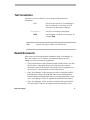
Before You Begin
The View Manager 16 Plus System Operator's Manual provides detailed
information about View Manager 16 Plus features, operation, and
application. It explains the step-by-step procedures that you will perform
when using the View Manager 16 Plus system. It is designed to be a
continuing source of information and reference as you use your View
Manager 16 Plus system.
In This Chapter
•
•
•
•
How To Use This Manual
Text Conventions
Related Documents
Support Services
How To Use This Manual
This manual is organized as follows:
viii
•
Chapter 1: About View Manager 16 Plus describes what View Manager
16 Plus does and how it is used. It also identifies the system's modes of
operation, and provides a brief overview of the TOUCH TRACKER and
POS/EM interface. In addition, it describes the equipment installed and
used with the View Manager 16 Plus system.
•
Chapter 2: Monitor Display Formats, describes the different formats in
which you can display video on the monitor, depending on whether your
system is connected to a quad splitter or a multiplexer.
•
Chapter 3: Controlling Cameras and Their Outputs, discusses how you
use the TOUCH TRACKER to control cameras—both manually and
automatically. It also describes how to toggle the state of a dome output,
and how to clear a dome alarm.
•
Chapter 4: Defining Automatic System Functions, provides procedures on
setting up system functions (such as Quick Views and Patterns) that the
user can initiate, as well as those system functions (such as dome alarms)
that happen automatically.
•
Chapter 5: TOUCH TRACKER Utilities, describes those system utilities that
are started from the menu, and provides instructions on using those
utilities.
•
Appendix A: Programming Worksheets, contains worksheets that will
make the task of programming your View Manager 16 Plus system
easier. There are worksheets provided for programming Quick Views,
Patterns, and the Sequence. In addition, there are worksheets for setting
up the alarms and worksheets that indicate which inputs and outputs are
connected to which domes.
Operator’s Manual
Text Conventions
This book uses text in different ways to identify different kinds of
information.
italics
monospace
bold
Note
used for terms specific to View Manager 16
Plus, items that you select from the LCD
menu, and text that requires emphasis
used for LCD messages and prompts
used for names of buttons on the keypad, for
example, Seq
Special notes appear inside a box like this one.
Related Documents
Other sources provide supplemental information about View Manager 16
Plus; these sources serve to enhance your understanding of the View
Manager 16 Plus system and its applications.
•
The Quick Reference Guide (document number 8000-2654-01) provides
quick reference information about some of the procedures that are
described in detail in this manual. It should be used as a supplement to—
not in place of—the information covered in this manual.
•
Some View Manager 16 Plus systems are used in conjunction with the
POS/EM Value system. The POS/EM Value System Administrator's
Manual (document number 8000-1488-01) provides instructions on how
to use View Manager 16 Plus to augment the POS/EM Value features.
•
Some View Manager 16 Plus systems are installed with a quad splitter.
The quad splitter's features can supplement the functionality of your
Before You Begin
ix
system. The documentation included with your quad splitter offers
programming and operation information for that unit.
•
Some View Manager 16 Plus systems are installed with a multiplexer.
The multiplexer's features can supplement the functionality of your
system. The documentation included with your multiplexer offers
programming and operation information for that unit.
•
Some View Manager 16 Plus systems are connected to a VCR. The
documentation included with your VCR offers programming and
operation information for that VCR.
Contact your Sensormatic Sales Representative if you need additional copies
of the View Manager 16 Plus Operator's Manual or any other support
documentation. The document number for this manual is 8000-2653-01; use
this number when ordering the manual.
Support Services
Sensormatic provides a variety of support services to help you get the most
from your View Manager 16 Plus system.
If you have a question about View Manager 16 Plus operation, and you
cannot find the answer in this document, consult with your Supervisor. If
your question has not been answered, contact the Sensormatic Help Desk at
1-800-241-6678.
Getting System Training and Consultation Services
If you feel that you require additional training, contact your Supervisor or
local Sensormatic Sales Representative to learn about supplemental training
options.
x
Operator’s Manual
C H A P T E R
1
A
B
Pe
el
Inf
Me
nu
o
C
1
Ou On
tpu
t
Off
2
D
3
4
Clea
r
5
Iris
Fli
6
7
Clo
se
8
Op
en
0
p
Vie
w
Pa
9
tte rn
Re
pea
Pa
tte rn t
Seq
Pre
v iou
s
Next
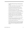
About View Manager 16 Plus
In This Chapter
•
•
•
•
•
•
Understanding Your View Manager 16 Plus System
View Manager 16 Plus Features
View Manager 16 Plus Equipment
Interfacing With the POS/EM Value System
An Overview of the TOUCH TRACKER
Modes of Operation
Understanding Your View Manager 16 Plus System
This manual describes those features that are available to you as a View
Manager 16 Plus operator, and it provides instructions for using these
features. It is up to you, however, to assimilate these features and apply them
in your specific environment.
Every site and situation has different concerns, capabilities, and
vulnerabilities. Understanding how your system works enables you to
address these concerns and overcome these vulnerabilities.
Use this manual to learn how to customize your system to meet the needs of
your environment. Most importantly, get comfortable using the system. The
more familiar you are with the system's features and functions, the better
prepared you will be at securing your site. Once you become comfortable
using the system, you will find it a valuable—and time-saving— security and
management tool.
View Manager 16 Plus Features
The View Manager 16 Plus system enables you to oversee activity
throughout your facility as it happens. This powerful overview allows you to
document activity and can help you to prevent unwanted activity from taking
place.
The system can include either one or two camera controllers, called TOUCH
TRACKERs. These TOUCH TRACKERs can control cameras simultaneously,
and enable two users to operate the system concurrently. As an alternative, a
single user could control both TOUCH TRACKERs at the same time for twohanded operation.
Features available to View Manager 16 Plus operators are:
1-2
•
The ability to manually call up video from individual cameras, one at a
time
•
The capability to display video from up to four cameras on one monitor
simultaneously in a 2x2 format by using a quad splitter
Operator’s Manual
•
The capability to display video from up to 16 cameras on one monitor
simultaneously in a 2x2 format, 3x3 format, or 4x4 format by using a
multiplexer
•
The capability to single-handedly control a camera's panning and tilting
movements, as well as its zoom, focus, and iris commands
•
An “Apple Peel” feature that allows a SpeedDome to run a default
pattern, providing you with complete video coverage of an area
•
A SpeedDome “flip” feature that enables you to flip the SpeedDome
180° in the opposite direction it is currently looking
•
The ability to define and display Quick Views, which are immediate
camera call-ups of pre-defined views, with automatic zoom and focus
•
The ability to define and run Patterns, which comprise a sequential series
of pan, tilt, zoom, and focus movements from a single camera
•
The capability to incorporate up to 16 of the pre-defined Quick Views
and Patterns in a Sequence, where the Quick Views and Patterns are
automatically displayed one after the other on the Main monitor
•
The capability to toggle the state of up to 64 dome outputs which, if
hooked up through relays, can control lights, door locks, etc., via the
TOUCH TRACKER
•
The ability to define up to 64 different alarms; the alarms are triggered
by dome inputs, and they automatically call up a pre-defined Quick
View, Pattern, or fixed shot and/or initiate a dome output
•
The ability to clear alarms via the Main TOUCH TRACKER; the system can
store up to four alarms at one time in its queue
•
Utilities that can be accessed from the TOUCH TRACKER. These utilities
include the following functions: reset the SpeedDome, select a language
for the TOUCH TRACKER's LCD display, adjust the LCD backlighting,
adjust the key click volume, and designate the Main and Call TOUCH
TRACKERs
About View Manager 16 Plus
1-3
View Manager 16 Plus Equipment
Every View Manager 16 Plus system consists of a unique set of equipment.
Some equipment is required; other equipment is optional.
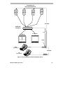
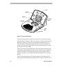
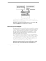
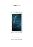
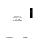
The following figure shows some components typically installed for a View
Manager 16 Plus system. This simplified illustration provides a broad
overview of the different types of equipment used and how the components
connect to one another.
1-4
Operator’s Manual
Programmable and
Non-Programmable Domes
SensorNet
Quad Splitter
or Multiplexer
RS 232
Call Monitor
Main Monitor
POS/EM
A
B
Pe
el
In fo
M en
Ou
u
2
Main
TOUCH TRACKER
5
F lip
6
7
se
Op
D
3
4
Iris
Clo
C
1
On
tp u
t
Of f
C lea
r
Vie
w
8
en
Pat
ter
n
Rep
Pat ea t
ter
n
S eq
9
0
P revi
ous
Nex
t
A
B
Pe
el
In fo
M en
Ou
u
2
5
Call
TOUCH TRACKER
Vie
w
8
P at
ter
n
Rep
Pat ea t
ter
n
S eq
9
en
0
P revi
SensorNet
F lip
6
7
se
Op
D
3
4
C lea
r
Iris
Clo
C
1
On
tp u
t
Of f
ous
Nex
t
Figure 1-1: Typical equipment used with View Manager 16 Plus.
About View Manager 16 Plus
1-5
1-6
•
The system's cameras enable you to monitor activity throughout a facility
from a single location. You can see video from up to 16 cameras. The
View Manager 16 Plus system is compatible with programmable and
non-programmable domes, PTZ cameras, and fixed cameras.
•
The TOUCH TRACKER is the device you use to select cameras and
manually control their movement, as well as adjust their zoom, focus,
and iris. The TOUCH TRACKER enables you to perform automated camera
operations and clear system alarms. With the TOUCH TRACKER you can
access the menu to program automated system functions and use the
utilities.
•
If there are two TOUCH TRACKERs installed with your system, you must
configure one as the Main TOUCH TRACKER and the other as the Call
TOUCH TRACKER. The Main TOUCH TRACKER employs all of the
functionality described in this manual. The Call TOUCH TRACKER,
however, has no programming capabilities, and it cannot select a monitor
display format, initiate the Sequence, or clear alarms.
•
The video monitor displays the cameras' video. You may have only one
monitor, you may have two monitors, or you may have a separate
monitor dedicated for every camera. If a system contains two monitors,
one is referred to as the Main monitor and the other as the Call monitor.
The Main monitor displays video in a multiplexed format, and its video
is controlled by the Main TOUCH TRACKER. The Call monitor is
dedicated for full-screen view only, and its video is controlled by the Call
TOUCH TRACKER.
•
The Quad Splitter or Multiplexer is the unit that allows video to be
displayed in a multiplexed format. The quad splitter enables you to see
video from up to four cameras simultaneously on one monitor. A
multiplexer enables you to see video from up to 16 cameras
simultaneously on one monitor.
•
The POS/EM Value system is used in conjunction with the View
Manager 16 Plus system. POS/EM Value enables you to automatically
view and record exception transactions that take place at the point of sale.
Operator’s Manual
Interfacing With the POS/EM Value System
Some View Manager 16 Plus systems interface with the Point-ofSale/Exception Monitoring (POS/EM) Value system. The POS/EM Value
system monitors the activity that takes place at the cash registers.
POS/EM Value documents those transactions that it considers exceptions to
the norm. When it documents one of these exceptions, it can print out the
actual register receipt and/or instruct a camera to view and record the
transaction as it happens.
When the system is in the camera control mode and an exception occurs at a
cash register, the POS/EM Value system can take control of a camera (if it
has been configured to do so). The POS/EM Value system will not affect the
View Manager 16 Plus system unless the TOUCH TRACKER is in the camera
control mode.
You can determine whether or not you want the POS/EM Value system to
have priority over your system's cameras. You use the C button on the Main
TOUCH TRACKER to indicate this. Each time you press the C button you
toggle back and forth between POS/EM priority over the cameras and View
Manager 16 Plus priority over the cameras.
If a “+” appears on the LCD, this indicates that POS/EM Value will take
control of a camera if an exception occurs at a register. If a “–” appears on
the LCD, this indicates that POS/EM Value will never take control of a
camera when an exception occurs.
The POS/EM Value system will only affect the Main monitor and the Main
TOUCH TRACKER. Should POS/EM take control over a camera, you will still
be able to use the Call TOUCH TRACKER as normal, and use it to select the
affected camera and manually take control of it.
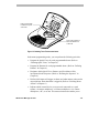
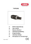
An Overview of the TOUCH TRACKER
The TOUCH TRACKER, shown here, is a video control station that provides
you with easy access to a variety of video control features—from basic
camera control to advanced automated functions.
About View Manager 16 Plus
1-7
LCD
Keypad
A
B
Pe
el
Info
Me
Zoom In
C
1
O
tpu n
t
Off
2
4
Cle
ar
5
Fli
6
7
e
Op
D
3
Ir is
Clo
s
Zoom Out
Ou
nu
V ie
8
en
p
w
Tracker
Ball
P att
ern
Re
p
P a eat
tte
rn
9
0
S eq
P re
vio
us
Ne
xt
Focus
Near
Focus Far
Figure 1-2: TOUCH TRACKER features.
The Tracker Ball provides variable speed control of a camera's pan and tilt.
The zoom and focus buttons enable you to control a camera's zoom and focus.
When used with the LCD menu, the zoom and focus buttons allow you to
select the menu items displayed on the LCD. The zoom in/out buttons are
located to the left of the Tracker Ball. The focus near/far buttons are located
to the right of the Tracker Ball.
The keypad contains buttons that call up video from individual cameras and
control the pre-programmed movement of those cameras. It also contains the
buttons for camera iris control, dome output control, and monitor display
formats. It also allows you to clear dome alarms from the TOUCH TRACKER
keypad.
The LCD, located at the top of the keypad, displays the currently selected
camera number, Pattern Number, and Quick View number. It enables you to
1-8
Operator’s Manual
see the numbers you enter from the keypad as you enter them. The LCD
displays system prompts and messages. It also displays the menu.
Modes of Operation
The TOUCH TRACKER has four different modes of operation:
•
Camera control mode
•
Menu/programming mode
•
Sequence mode
•
Alarm mode
The system functions differently depending on the mode of operation. The
following sections describe each of these modes.
Camera Control Mode
When the TOUCH TRACKER is in the camera control mode, you can:
•
Determine the display format used for viewing video from cameras on
the monitor. (Refer to Chapter 2, “Monitor Display formats”)
•
Select individual cameras and display their video on the monitor. (Refer
to Chapter 3, “Controlling Cameras and Their Outputs”)
•
Control cameras manually. (Refer to Chapter 3, “Controlling Cameras
and Their Outputs”)
•
Initiate automatic system functions. (Refer to Chapter 3, “Controlling
Cameras and Their Outputs”)
•
Display the ID code for the currently selected dome. (Refer to
“Displaying a Dome's ID Code,” in Chapter 5.)
•
Designate whether or not POS/EM Value will have priority over cameras
when an exception takes place. (Refer to the section “Interfacing With
the POS/EM Value system” in this chapter.)
About View Manager 16 Plus
1-9
In the camera control mode, the selected camera number appears on the LCD.
If there is a Quick View or a Pattern running, this is also indicated.
In this mode, the Tracker Ball functions as the camera pan/tilt controller, and
the zoom and focus buttons control the zoom and focus of the currently
selected camera.
When the system is in the camera control mode, POS/EM Value has the
ability to take control over the View Manager 16 Plus cameras if it has been
configured to do so.
Menu/Programming Mode
You activate the menu/programming mode by pressing the Menu button on
the keypad. When the TOUCH TRACKER is in the menu/programming mode,
the LCD displays the available menu selections, and the Tracker Ball
functions as a cursor controller, enabling you to scroll through the menu
selections.
The zoom and focus buttons enable you to select an item on the menu. There
are always two menu items visible at one time on the LCD. Use a zoom
button to select the item on the top line. Use a focus button to select the item
on the bottom line.
Tip: You may also use the A or B buttons on the TOUCH TRACKER to select
menu items on the LCD. Use A to select the top item on the LCD; use B to
select the bottom item on the LCD.
The C and D buttons on the TOUCH TRACKER may be used to scroll through
the LCD menu. Use C to scroll to the previous menu item; use D to scroll to
the next menu item.
1-10
Operator’s Manual
A
B
Pe
el
Info
Me
Press a zoom button
to select the top line
of the LCD.
Ou
nu
2
4
Cle
ar
5
Fli
6
7
e
Op
D
3
Ir is
Clo
s
C
1
O
tpu n
t
Off
V ie
8
en
p
w
P att
ern
Re
p
P a eat
tte
rn
9
0
S eq
P re
vio
us
Ne
xt
Press a focus button to
select the bottom line
of the LCD
Figure 1-3: Selecting TOUCH TRACKER menu items.
In the menu/programming mode, you can perform the following activities:
•
Program the Quick Views for each programmable dome. (Refer to
“Defining Quick Views” in Chapter 4.)
•
Program the Patterns for each programmable dome. (Refer to “Defining
Patterns” in Chapter 4.)
•
Designate which Quick Views, Patterns, and fixed shots will be
incorporated in the Sequence. (Refer to “Defining the Sequence” in
Chapter 4.)
•
Define which inputs will trigger an alarm, and what camera action and/or
output initiates when that alarm is triggered. (Refer to “Defining Dome
Alarms” in Chapter 4.)
•
Indicate which external device your system is connected to: a quad
splitter, a 4-camera multiplexer, a 9-camera multiplexer, a 16-camera
multiplexer, a PC, or no unit. This menu selection also enables you to
About View Manager 16 Plus
1-11
indicate if you are connected to a POS/EM Value system. (Refer to
“Choosing the External Unit for the TOUCH TRACKER” in Chapter 2.)
•
Reset a SpeedDome if it is not responding as expected to TOUCH
TRACKER commands. (Refer to “Resetting a Dome” in Chapter 5.)
•
Select from 10 different languages in which to display the LCD text.
(Refer to “Selecting a Language” in Chapter 5.)
•
Assign the Main and Call TOUCH TRACKERs. (Refer to “Designating
Main Versus Call TOUCH TRACKER,” in Chapter 5.)
•
Adjust LCD backlighting. (Refer to “Adjusting LCD Brightness” in
Chapter 5.)
•
Adjust the key click sound. (Refer to “Turning Key Click On / Off” and
“Adjusting Key Click Volume” in Chapter 5.)
When the system is in the menu/programming mode, POS/EM Value will
never assume control over the View Manager 16 Plus cameras, even if it has
been configured to do so.
Sequencing Mode
You activate the sequencing mode by pressing the Seq button; this initiates
the Sequence you defined in the menu/programming mode.
The Sequence consists of up to 16 of the previously defined Quick Views and
Patterns (called events). These events run one after the other on the monitor.
The sequencing mode provides you with an unattended surveillance of your
facility; it runs continuously until you stop it manually.
When the TOUCH TRACKER is in the sequencing mode, the LCD displays the
camera number whose video appears on the monitor. It also displays the
event number (1 through 16) that the Sequence is currently displaying. In
addition, the LCD displays how many seconds the current event will remain
on the screen until the next event occurs.
When the system is in the sequencing mode, POS/EM Value has the ability
to take control over the View Manager 16 Plus cameras if it has been
configured to do so.
1-12
Operator’s Manual
For more information on the sequencing mode, refer to the section “Running
the Sequence,” in Chapter 3.
Alarm Mode
Regardless of the current mode of the system, the TOUCH TRACKER will
automatically go into the alarm mode when an alarm is triggered. When the
alarm mode is active, the TOUCH TRACKER beeps intermittently for 60
seconds if you have Automatic Alarm Acknowledging enabled (or you clear
the alarm by pressing the Clear button).
You set up the alarms in the programming mode. When you set up an alarm,
you determine what will trigger the alarm, and what the alarm will do when it
is triggered. The following illustration shows an example of the TOUCH
TRACKER LCD in the alarm mode.
Cam 3 Alarm2
Src: Cam5 Inp3
In the previous example, there are currently two alarms active. The alarm
whose information appears on the LCD was triggered by input 3 of camera 5.
The video from camera 3 currently appears on the Main monitor.
When the system is in the alarm mode, POS/EM Value will never assume
control over the View Manager 16 Plus cameras, even if it has been
configured to do so.
For more information on the alarm mode, refer to the section “Clearing
System Alarms,” in Chapter 3.
About View Manager 16 Plus
1-13
NOTES:
1-14
Operator’s Manual
C H A P T E R
2
A
B
Pe
el
Inf
Me
nu
o
C
1
Ou On
tpu
t
Off
2
D
3
4
Clea
r
5
Iris
Fli
6
7
Clo
se
8
Op
en
0
p
Vie
w
Pa
9
tte rn
Re
pea
Pa
tte rn t
Seq
Pre
v iou
s
Next
Monitor Display Formats
The View Manager 16 Plus system enables you to manually call up
individual cameras and display their video in the full-screen format. If your
View Manager 16 Plus system is connected to a quad splitter or a
multiplexer, there are several other display formats available to you.
In This Chapter
•
•
•
Choosing the External Unit for the TOUCH TRACKER
Displaying Video with Quad Splitters
Displaying Video with Multiplexers
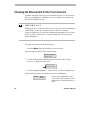
Choosing the External Unit for the TOUCH TRACKER
You must assign the correct type of external unit for your TOUCH TRACKER.
It may be a quad splitter, a multiplexer, or a PC. If there is no external unit,
this must be indicated as well.
IMPORTANT
Although the TOUCH TRACKER allows you to select any of the configurations
via this menu, it will only recognize the unit to which it is actually
connected. Make sure you select the configuration that applies to your setup.
If your system is connected to a 16-camera multiplexer, do not select a 9camera multiplexer.
To assign the external unit, do the following:
1. Press the Menu button on the Main TOUCH TRACKER.
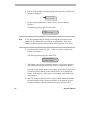
The menu appears on the LCD. It looks like this:
Define Sequence
Setup View
2. Use the Tracker Ball to scroll through the selections until “Config
Devices” is displayed on the LCD.
Alarm Actions
Config Devices
3. Press the appropriate button— zoom or focus—to select Config Devices.
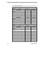
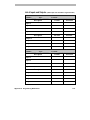
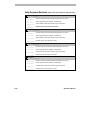
Use the following chart to determine your correct configuration.
Device = Quad
= POSEM
2-2
Choose this configuration if your
TOUCH TRACKER is connected to a
quad splitter, a POS/EM system, or
both
Operator's Manual
Device = Mux 4
= POSEM
Choose this configuration if your
TOUCH TRACKER is connected to a
4-camera multiplexer, a POS/EM
system, or both.
Device = Mux 9
= POSEM
Choose this configuration if your
TOUCH TRACKER is connected to a
9-camera multiplexer, a POS/EM
system, or both.
Device = Mux 16
= POSEM
Choose this configuration if your
TOUCH TRACKER is connected to a
16-camera multiplexer, a POS/EM
system, or both.
Device = PC
Choose this configuration if your
TOUCH TRACKER is connected to a
PC. This selection is used by service
personnel only.
Device = None
Choose this configuration if your
TOUCH TRACKER is not connected
to any external systems
4. Use the Next button to scroll through the list of available choices.
5. When the appropriate configuration is displayed on the LCD, press the
Menu button.
Monitor Display Format
2-3
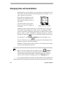
Displaying Video with Quad Splitters
Quad splitters give you the ability to see video from up to eight cameras. The
video can be viewed from each camera individually (refer to Chapter 3), or it
can be displayed in quad mode.
When cameras are displayed in the
quad mode, you will be able to see
video from four cameras at once on
the monitor
The camera number appears in the
bottom of its respective quadrant on
the monitor.
1
2
3
4
QUAD DISPLAY MODE
Although as many as eight cameras may be connected to your system, only
four cameras can be displayed at one time. If your View Manager 16 Plus
system is connected to a dual page quad splitter, the cameras will be divided
into two “pages.” Cameras 1 through 4 are displayed on page one; cameras 5
through 8 are displayed on page two. To switch back and forth between page
one and page two, press
(the Display button) on the Main TOUCH
TRACKER. Each time you press
, you change the monitor display from
page one, to page two, to full-screen display.
Regardless of which display format you choose, you will always have control
over the camera indicated on the LCD.
Tip: If your system includes only one monitor, press the
(Display
button) to put the monitor in the quad display format. Press the number
associated with an individual camera to call that camera to the full-screen
mode (or select the full-screen display mode via the Display button).
If your system includes two monitors, the Main monitor will be dedicated for
2-4
Operator's Manual
quad display and the Call monitor will be dedicated for full-screen display.
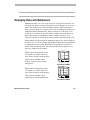
Displaying Video with Multiplexers
Multiplexers allow you to see video from up to 16 cameras at one time. You
can either call up these cameras individually (refer to Chapter 3), or you can
display the cameras in one of the multiplexed modes. Duplex multiplexers
allow you to record up to 16 cameras at one time and display the cameras in a
multiplexed mode simultaneously. Simplex multiplexers will allow you to
record up to 16 cameras at one time (while viewing cameras full screen) or
display the cameras in a multiplexed mode. In either case, the TOUCH
TRACKER provides for control of the camera number appearing on the LCD.
When cameras are displayed in the multiplexed mode, they can be displayed
in either a 2x2, 3x3, or 4x4 format, depending on which model of multiplexer
is configured for your system. Multiplexers are available in 4-camera, 9camera, and 16-camera models. The camera number always appears in its
respective window on the monitor.
When cameras are displayed in the
2x2 format, you will be able to see
video from 4 cameras on the monitor.
This format is available with 4camera, 9-camera, and 16-camera
multiplexers.
When cameras are displayed in the
3x3 format, you will be able to see
video from 9 cameras on the monitor.
1
2
3
4
2x2 DISPLAY FORMAT
1
2
3
4
5
6
7
8
9
This format is available with 9camera and 16-camera multiplexers.
3x3 DISPLAY FORMAT
Monitor Display Format
2-5
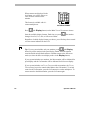
When cameras are displayed in the
4x4 format, you will be able to see
video from 16 cameras on the
monitor.
This format is available with 16camera multiplexers.
Press
1
2
3
5
6
7
4
8
9
10
11
12
13
14
15
16
4x4 DISPLAY FORMAT
(the Display button) on the Main TOUCH TRACKER to choose
from the available display formats. Each time you press
changes from 2x2, 3x3, 4x4, or full-screen format.
, the monitor
Regardless of which display format you choose, you will always have control
over the camera indicated on the LCD.
Tip: If your system includes only one monitor, press
(the Display
button) to put the monitor in the quad display format. Press the number
associated with an individual camera to call that camera to the full-screen
mode (or select the full-screen display mode via the Display button).
If your system includes two monitors, the Main monitor will be dedicated for
quad display and the Call monitor will be dedicated for full-screen display.
If your system includes one TOUCH TRACKER with two monitors, the TOUCH
TRACKER may be used to control either Main or the Call monitor. To switch
control to the Call monitor, press the Sel button twice on the multiplexer. To
return control to the Main monitor, press the Sel button again.
2-6
Operator's Manual
C H A P T E R
3
A
B
Pe
el
Inf
Me
nu
o
C
1
Ou On
tpu
t
Off
2
D
3
4
Clea
r
5
Iris
Fli
6
7
Clo
se
8
Op
en
0
p
Vie
w
Pa
9
tte rn
Re
pea
Pa
tte rn t
Seq
Pre
v iou
s
Next
Controlling Cameras and Their Outputs
In This Chapter
•
•
•
•
•
•
•
•
•
•
•
•
•
How the System Resolves Conflicts in Camera Control
Selecting a Camera
Stepping Through the Cameras
Controlling a Camera's Pan and Tilt
Controlling Zoom and Focus
Controlling the Iris
“Flipping” the SpeedDome
Running the “Apple Peel” Pattern
Displaying Quick Views
Running Patterns
Running the Sequence
Controlling Dome Outputs
Clearing System Alarms
How the System Resolves Conflicts in Camera Control
If your system configuration includes two TOUCH TRACKERs, the Main
TOUCH TRACKER will always have priority over the Call TOUCH TRACKER
when the system is in the camera control mode. Whichever camera the Main
operator has selected will be “locked” and the Call operator will not be able
to control it. The Call operator may select the camera and display its video on
the Call monitor; however, he or she will not be able to control the locked
camera.
If the Call operator attempts to control a camera that is currently selected by
the Main operator, the message, “Camera In Use” appears on the Call
TOUCH TRACKER. If the Main operator selects a camera that is currently in
use by the Call operator, the message, “Camera Override” appears on
the Call TOUCH TRACKER. The Main operator will then secure control of the
camera.
The Main operator maintains control over a camera until one of the following
things happens:
•
The Main operator selects a new camera
•
The Main operator enters the menu/programming mode
•
The Main operator initiates the Sequence
•
An alarm comes into the system
•
The selected camera remains idle for 3 minutes
Once the Main operator relinquishes control of a camera for any of the
reasons mentioned above, the message, “Camera Free” appears on the
Call TOUCH TRACKER (if the Call operator has that camera selected).
Selecting a Camera
Each camera has a unique number associated with it. To select a camera, use
(the
the number buttons to enter the camera number, and then press
Camera button). The video from that camera appears in the full-screen
3-2
Operator's Manual
mode on the monitor, and the associated camera number appears in the
bottom left corner of that monitor.
If you select a camera via the Main TOUCH TRACKER, its video appears on
the Main monitor. If you select a camera via the Call TOUCH TRACKER, its
video appears on the Call monitor.
Stepping Through the Cameras
The Previous and Next buttons enable you to manually step through all of
the cameras, one at a time. Press the Previous and Next buttons to step
backward and forward through all of the cameras configured for your system.
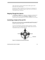
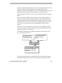
Controlling a Camera's Pan and Tilt
Once you have selected a camera, you can manually control the movement of
that camera. Pan is the side to side movement of the camera. Tilt is the up
and down movement of the camera.
You use the Tracker Ball to control the camera's pan and tilt. To pan the
camera, move the Tracker Ball left and right. To tilt the camera, move the
Tracker Ball toward you or away from you.
Tilt up
Pan left
Pan right
Tracker Ball
Tilt down
Figure 3-1: The Tracker Ball controls panning and tilting.
Controlling Cameras and Their Outputs
3-3
You can simultaneously pan and tilt the camera for diagonal movement. For
example, move the Tracker Ball diagonally up and to the right; this moves
the camera up and to the right.
The speed of the camera movement is directly proportional to how far you
move the Tracker Ball from its center position. If you move the Tracker Ball
slightly to the right, the camera will pan slowly to the right. As you move the
Tracker Ball farther to the right, the camera's panning speed will increase
until it reaches its maximum speed. This variable speed operation applies to
programmable domes only. Non-programmable domes provide two speeds:
normal and fast.
Controlling Zoom and Focus
Once you have selected a camera, you can control the zoom and focus
settings of that camera. The following illustration shows the location of the
zoom and focus buttons.
Zoom In
Zoom Out
Focus Near
Focus Far
Figure 3-2: Zoom and Focus Controls.
Zooming In and Out
Zoom refers to adjusting the magnification of the camera lens to make an
object appear closer (larger) or farther away (smaller). To make objects
appear closer to the camera, press the zoom in button. To make objects
appear further from the camera, press the zoom out button. If you quickly
press and release a zoom button, there will be only a slight visible change on
3-4
Operator's Manual
the monitor. The longer you press the zoom in/out button, the more
noticeable will be the response.
Focusing the Camera
Focus refers to the process of adjusting the clarity of a scene or an object, as
seen through a camera. To adjust the focus on the object or scene displayed
on the monitor, press a focus button. You can either focus near (if the object
is closer than the current focus setting) or far (if the object is farther away
than the current focus setting). You will see the scene on the monitor become
either sharper and clearer or fuzzier and less clear. Like the zoom buttons, the
focus buttons react based on the length of time it is pressed; the longer you
press the button down, the more noticeable will be the response.
Controlling the Iris
Normally, the brightness and darkness of the picture are controlled by the
camera's auto gain function and the auto/manual iris function. However, there
may be times when you would prefer to see the picture on the monitor be
even darker or lighter. There are buttons on the keypad that enable you to
control the camera's iris, which is the device that regulates the brightness or
darkness of the picture.
To make the picture brighter, press the Iris Open button. To make the
picture darker, press the Iris Close button.
To return the iris to its default setting, press both iris buttons simultaneously.
“Flipping” the SpeedDome
You can flip a SpeedDome 180° in the opposite direction. The SpeedDome
flip is especially useful when you are tracking a subject who walks directly
under the SpeedDome and then continues walking on the other side of the
SpeedDome.
Controlling Cameras and Their Outputs
3-5
To flip the currently selected SpeedDome, press the Flip button on the
keypad. When you flip a SpeedDome, the LCD displays the following
message:
Cam x
Flip Dome
+
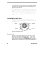
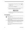
Running the “Apple Peel” Pattern
You can instruct a SpeedDome to run the Apple Peel pattern. This is a default
pattern that all SpeedDomes can run without any user programming.
The Apple Peel pattern consists of three
revolutions of camera panning, with tilt starting at
the ceiling. Each revolution tilts down
approximately 30°. The Apple Peel pattern
provides you with a complete view of the area.
Apple Peel Pattern
Note
If you are using the View Manager 16 Plus system with a Sensornet-to-RS422 Code Converter, pressing Peel will run Pattern 3 for the currently
selected dome if Pattern 3 has been programmed.
The following procedure describes how to initiate the Apple Peel pattern.
1. Use the number buttons to enter the number of the SpeedDome for which
you want to initiate the Apple Peel pattern (for example, camera 2). Then
press the Camera button.
2. Press the Peel button.
The LCD displays the following message:
3-6
Operator's Manual
Cam 2
+
Apple Peel Patn
The Apple Peel pattern will repeat itself indefinitely until you issue a camera
command (pan, tilt, zoom, focus, or iris) to the dome running the pattern.
Displaying Quick Views
IMPORTANT
The SpeedDome Ultra III and newer domes support up to 96 views. Other
domes support up to 4 views. The Touch Tracker beeps when you attempt to
call up a view numbered higher than 4 on domes older than the SpeedDome
Ultra III.
A Quick View enables you to instantaneously call up a specific view from a
programmable dome, regardless of where that dome is currently pointing. A
Quick View is useful when you want to look at a particular item or area
immediately. You may not want to have to manually pan and tilt the camera
to the specific area, and then zoom and focus.
You can define your own Quick Views to support your specific needs. Refer
to Chapter 4, “Defining Automatic System Functions,” for procedures on
defining Quick Views.
The View button on the keypad allows you to call up the Quick Views that
you have defined for your cameras. Depending on the type of dome, either 4
or 96 Quick Views may be defined.
If a list has been compiled for your facility, you can refer to the List of Quick
Views in Appendix A to determine which Quick Views are available for
which domes.
The following procedure describes how to display a Quick View.
Controlling Cameras and Their Outputs
3-7
1. Use the number buttons to enter the number of the camera whose Quick
View you want to display, for example, camera 12. Then press
(the Camera button).
2. Use the number buttons to enter the number of the Quick View you want
to display, and then press the View button.
If the Quick View exists for the selected camera, the camera will immediately
point to the pre-defined Quick View, and then zoom and focus
automatically. The following message appears on the LCD:
Cam 12
View
+
If you attempt to call up a Quick View for a non-programmable dome, or
if you entered an invalid View number (any number greater than 96), the
TOUCH TRACKER beeps.
Running Patterns
IMPORTANT
The SpeedDome LT supports a feature called “Auto Pan” that allows you to
program a smooth side-to-side camera movement for an area. Please refer to
the section in Chapter 4 titled “SpeedDome LT Auto Pan Programming” for
additional information.
A Pattern is a sequential series of pan, tilt, zoom, and focus movements from
a single camera. You “teach” the camera a combination of these movements.
Then when you run the Pattern, the camera automatically repeats the
movements you taught it.
You can define your own Patterns to support your specific needs. Refer to
Chapter 4, “Defining Automatic System Functions,” for procedures on
defining Patterns.
3-8
Operator's Manual
When you run a Pattern, you can specify to run the Pattern once, or you can
specify to run the Pattern repeatedly until you stop it manually. Both methods
are described here.
If a list has been compiled for your facility, you can refer to the List of
Patterns in Appendix A to determine which Patterns are available for which
domes.
The following procedure describes how to run a Pattern. Most programmable
domes support up to three Patterns defined for it. The SpeedDome LT will
support programming the Auto Pan feature for Pattern 1; it does not support
programming any additional patterns.
1. Use the number buttons to enter the number of the camera whose Pattern
(the Camera button).
you want to run. Then press
2. Use the number buttons to enter the number of the Pattern you want to
run. Then press the Pattern button (if you want the Pattern to run one
time and then stop), or press the Repeat Pattern button (if you want the
Pattern to repeat indefinitely until you stop it).
If that Pattern exists for that camera, the Pattern will automatically begin
running. If that Pattern does not exist for that camera, the camera will run
the default Apple Peel pattern, described previously.
Depending on whether this is a Pattern that will run once or a repeating
Pattern, one of the following messages appears on the LCD:
Cam 8
Run Pattern
+
-or-
Cam 8
+
Repeat Pattern
If you instructed the Pattern to run through one time, the following
message appears on the LCD once the Pattern is complete:
Cam 8
+
Pattern Done
If you instructed the Pattern to repeat itself, the Pattern will continue
running until you manually issue a camera command (pan, tilt, zoom,
focus, or iris) to the dome running the Pattern.
Controlling Cameras and Their Outputs
3-9
If you tried to run a Pattern for a non-programmable dome, or if you
entered an invalid Pattern number (any number greater than 3), the
TOUCH TRACKER beeps.
Running the Sequence
Tip: The Sequence can be initiated from the Main TOUCH TRACKER only.
The Sequence consists of a collection of Quick Views and Patterns that have
been defined for your system's cameras. In the Sequence you can also include
fixed shots from any camera. The Sequence can include up to 16 of these
Quick Views, Patterns, and fixed shots; these are referred to as the “events”
of the Sequence. When the Sequence is running, these events are
automatically displayed one after the other on the Main monitor. Each event
remains on the monitor for a specific duration time (from 1 to 90 seconds);
the duration time can be different for each event.
You can define the Sequence that most adequately supports your specific
needs. Refer to Chapter 4, “Defining Automatic System Functions,” for
procedures on defining the Sequence.
To run the Sequence, press the Seq button on the Main TOUCH TRACKER.
The Sequence automatically begins running and the information shown here
appears on the LCD.
3-10
Operator's Manual
This is the camera whose
Quick View, Pattern or fixed
shot appears on the monitor.
Cam 3
Sequencing
This is the event number
assigned to this Quick View,
Pattern, or fixed shot in the
Sequence.
6
12
This indicates how many
seconds are remaining until
the monitor switches to the
next event in the Sequence.
As the Sequence is running, the LCD indicates which camera's video is
displayed, which event in the Sequence is active, and how many seconds are
remaining in that event's duration time.
The Sequence will repeat itself indefinitely until you press either the Seq
button or the Clear button on the Main TOUCH TRACKER.
Controlling Dome Outputs
The programmable domes at your facility can have output devices connected
to them. Output devices are hardware components that can be controlled by
the system. Typical output devices include gates, door strikes, and lights.
Each dome can have up to four output devices connected to it. You can
control the state of any output device that is connected to the currently
selected dome using the TOUCH TRACKER.
Up to 64 output devices can be configured at a single facility. It might be
useful to post the List of Inputs and Outputs, which is included in Appendix
A, next to the TOUCH TRACKER. This chart lists which output devices are
connected to which domes at your facility. Posting such a list next to the
TOUCH TRACKER enables operators to easily determine what outputs are
available, and which buttons correspond to those outputs.
The following procedure describes how to turn a dome output on and off.
The on and off states for each dome output are also listed on the List of
Controlling Cameras and Their Outputs
3-11
Inputs and Outputs. You must know the number of the dome (1 – 16) that the
output is connected to, and the output number (1– 4) before you begin this
procedure.
1. Refer to your List of Inputs and Outputs to determine which output you
want to turn on or off.
2. Use the number buttons to enter the number of the camera whose output
state you want to toggle. Then press
(the Camera button).
3. Use the number buttons to enter the number of the output you want to
control. Then press the Output On button (if you want to turn the output
on), or press the Output Off button (if you want to turn the output off).
The List of Inputs and Outputs provides the on and off states for each
output.
Depending on whether you turned the output on or off in the previous
step, the LCD displays one of the following messages:
Cam 13
Output On
+
-or-
Cam 13
Output Off
+
If you entered an invalid output number (any number greater than 4 or an
output that does not exist) the TOUCH TRACKER beeps.
Clearing System Alarms
Tip: Alarms can be cleared from the Main TOUCH TRACKER only.
Your system can be configured to handle up to 64 different alarms. When an
alarm is triggered, it takes precedence over whatever you are doing on the
Main monitor and Main TOUCH TRACKER at the time. For example, if you
are in the programming mode when an alarm comes in, the alarm information
3-12
Operator's Manual
replaces the programming information. If you are running the Sequence when
an alarm comes in, the alarm information will replace the Sequence
information on the LCD. In addition, the video information for the alarm will
replace the video information for the Sequence on the Main monitor.
The Call monitor and Call TOUCH TRACKER remain unaffected by incoming
alarms.
Each alarm can be configured to automatically call up video and initiate an
output. For example, when an alarm is triggered, it can automatically run a
specific Pattern and set off an audible alarm. In addition, whenever an alarm
is triggered, the TOUCH TRACKER will beep, signaling an active alarm. The
TOUCH TRACKER will continue to beep intermittently until the alarm is
cleared.
There can be up to four alarms active at one time. If more than four alarms
are active at one time, and none of them have been acknowledged, the oldest
alarm gets “pushed out” of the queue.
The following illustration is an example of what the LCD looks like when
one or more alarms are active.
This is the camera whose
video appears on the
monitor during the alarm.
Cam 3
Src
This indicates how many
alarms are currently
active.
Alarm2
Cam 5 Inp3
This is the number associated with
the specific input that triggered the
alarm, and the number of the
Camera to which that input is
connected.
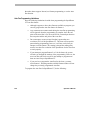
The system default setting is to automatically clear alarms after 60 seconds.
No action is required by the operator to clear alarms as long the automatic
Controlling Cameras and Their Outputs
3-13
alarm acknowledgment is enabled. However, alarms can always be cleared
by pressing the Clear button on the Main TOUCH TRACKER.
Press the Clear button on the Main TOUCH TRACKER to manually clear the
alarm whose information appears on the LCD and whose video appears on
the Main monitor. When you clear an alarm, its associated output returns to
its original state, and its information is cleared from the LCD. Continue to
press the Clear button until all active alarms have been cleared.
The TOUCH TRACKER stops beeping when all active alarms have been
cleared. If the TOUCH TRACKER was running the Sequence before the alarm
came in, it will restart the Sequence from the beginning. If you were in the
middle of programming when the alarm came in, you will have to resume
programming from the beginning.
3-14
Operator's Manual
C H A P T E R
4
A
B
Pe
el
Inf
Me
nu
o
C
1
Ou On
tpu
t
Off
2
D
3
4
Clea
r
5
Iris
Fli
6
7
Clo
se
8
Op
en
0
p
Vie
w
Pa
9
tte rn
Re
pea
Pa
tte rn t
Seq
Pre
v iou
s
Next
Defining Automatic System Functions
In This Chapter
•
•
•
•
•
•
Defining a Quick View
Defining a Pattern
Understanding Sequence Programming
Defining the Sequence
Setting Up System Alarms
SpeedDome LT Auto Pan Programming
Defining a Quick View
IMPORTANT
The SpeedDome Ultra III and newer domes support up to 96 views. Other
programmable domes support up to 4 views. The TOUCH TRACKER beeps
when you attempt to program a view numbered higher than 4 on domes older
than the SpeedDome Ultra III.
A Quick View automatically and instantaneously calls up a view from a
programmable dome, regardless of where that dome is currently pointing.
You can define your own Quick Views to support your specific needs.
Depending on the type of dome, either 4 or 96 views may be defined.
Tip: You must use the Main TOUCH TRACKER to define Quick Views.
The following procedure describes how to define a Quick View.
1. Using the number buttons, enter the number of the programmable camera
for which you are defining this Quick View (for example, camera 7).
Then press
(the Camera button).
2. Pan and tilt the camera so that it is pointing at the view you want to
define. Then zoom and focus the camera accordingly.
3. When you have the perfect scene displayed on the monitor, press the
Menu button.
The TOUCH TRACKER is now in the menu/programming mode, and the
menu appears:
Define Sequence
Setup View
4-2
Operator's Manual
4. Use the Tracker Ball to scroll through the menu selections until Setup
View is displayed on the LCD.
Setup View
Record Pattern
5. Press the appropriate button, zoom or focus, to select Setup View.
The following prompt appears on the LCD:
Cam 7
Enter View#?
Note
If you press a number that has been assigned to an existing Quick View for
this camera, the new Quick View will overwrite the existing Quick View.
There is no warning to indicate that the existing Quick View will be
replaced. Use caution.
6. Press the number on the keypad (1 - 96) that you want to assign to this
Quick View, then press Zoom or Focus.
The following message appears briefly on the LCD:
Cam 7
View Saved
If you press an invalid number (any number greater than 96), the TOUCH
TRACKER beeps, and the system will not save the Quick View. If this
happens, simply press a valid number and the Quick View will be saved.
The TOUCH TRACKER automatically returns to the camera control mode.
In the List of Quick Views (found in Appendix A), make a record of the
Quick View you just defined, including a brief description of what the Quick
View is “looking at.”
Defining Automatic System Functions
4-3
Tip: A shortcut method for defining Quick Views is available. Press Menu,
View, the Quick View number, and Zoom or Focus to create a Quick
View of the current scene.
Defining a Pattern
Note
The SpeedDome LT does not support Pattern programming. Refer to the
section in this chapter titled “SpeedDome LT Auto Pan Programming” for
information about setting the Auto Pan feature.
You can define your own Patterns to support your specific needs.
You can program up to three Patterns per programmable dome. The length
and complexity of a Pattern are restricted by two variables:
•
•
Number of camera commands
Time
Each time you move the camera in any direction, zoom in or out, focus near
or far, or adjust the iris, you have issued camera commands to the camera.
The three Patterns for a dome can collectively consist of up to 98 camera
commands. As you program a Pattern, the number of camera commands
remaining for that camera appears on the TOUCH TRACKER LCD.
There is also a time constraint on Patterns. A single Pattern cannot have a
duration longer than approximately 6 minutes and 50 seconds. Even if a
Pattern has only two camera commands in it, the Pattern will stop recording
once its duration time has elapsed.
4-4
Operator's Manual
Patterns are programmed in real-time. This means that the camera is
remembering every programming command you make at the actual speed
you issue the commands. For example, if you let the camera sit still for 20
seconds during programming, the camera pause for 20 seconds each time that
Pattern runs in the future. The 20 seconds of “non-motion time” is part of the
Pattern.
Tip: You must use the Main TOUCH TRACKER to define Patterns.
If you make a mistake during programming or you no longer want to
program the Pattern, press the Menu or the Clear button at any time to
cancel programming. The TOUCH TRACKER returns to the camera control
mode.
The following procedure describes how to define a Pattern.
1. Using the number buttons, enter the number of the programmable camera
for which you are defining the Pattern (for example, camera 3). Then
press the Camera button.
2. Pan and tilt the camera to the starting point of the Pattern, and then zoom
and focus the camera accordingly.
3. When you have the perfect “starting point” picture displayed on the
monitor, press the Menu button.
The TOUCH TRACKER is now in the menu/programming mode, and the
menu appears:
Define Sequence
Setup View
Defining Automatic System Functions
4-5
4. Use the Tracker Ball to scroll through the menu selections until Record
Pattern is displayed.
Record Pattern
Alarm Actions
5. Press the appropriate button—zoom or focus—to select Record
Pattern.
The following prompt appears on the LCD:
Cam 3
Enter Patrn#?
Note
If you press a number that has already been assigned to a Pattern for this
camera, the new Pattern will overwrite the existing Pattern. There is no
warning to indicate that the existing Pattern will be replaced. Use caution.
6. Press the number on the keypad (1 - 3) that you want to assign to this
Pattern, for example 1.
The following message appears on the LCD:
Record Pattern 1
Finish w <Next>
7. The Pattern is now being recorded in real-time. If you let the camera sit
still at this point, that non-motion time will be recorded in the Pattern.
If you pressed an invalid number (any number greater than 3), the TOUCH
TRACKER will beep and the system will not allow you to program the
Pattern. If this happens, simply press a valid number and continue with
this procedure.
8. Move the camera around and create a logical, usable Pattern. Remember,
the three Patterns for this camera can collectively incorporate up to 98
camera commands, and each Pattern can be up to 6 minutes and 50
4-6
Operator's Manual
seconds long. The number of remaining commands for this camera
appears on the LCD as you program the Pattern.
9. When you complete programming the Pattern, press the Next button.
The following message appears on the LCD:
Cam 3
Pattern Saved
The TOUCH TRACKER automatically returns to the camera control mode.
In the List of Patterns (in Appendix A of this manual), make a record of the
Pattern you just defined, including a brief description of the Pattern.
Tip: A shortcut method for defining Patterns is available. Press Menu,
Pattern, and the Pattern number. Move the camera in the desired pattern,
then press Next when finished.
Understanding Sequence Programming
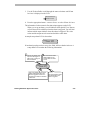
You can define a Sequence that incorporates up to 16 events. An event is a
Quick View or Pattern that you have already defined; an event can also be a
fixed shot. The events that you include in the Sequence can be defined for
any camera. For each event, you designate a duration time, which indicates
how long that event will remain on the monitor before the Sequence switches
to the next event.
Before you begin defining the Sequence, you should have a clear
understanding what you want to include in the Sequence. Refer to the lists
that you compiled (in Appendix A) of the available Quick Views and
Patterns. Make sure you can answer the following questions:
Defining Automatic System Functions
4-7
•
Which Quick Views, Patterns, and fixed shots will you include in the
Sequence?
•
What are the numbers that were assigned to those Quick Views and
Patterns when they were defined?
•
What are the camera numbers that the Quick Views and Patterns were
defined on? What are the camera numbers whose fixed shots you want to
include?
It is recommended that you to fill out the Setup Sequence Worksheet in
Appendix A before you begin setting up the Sequence. On the Setup
Sequence Worksheet, you can list all of the events—along with their
numbers, the cameras on which they were defined, and their duration times—
to be included in the Sequence. You can then refer to this worksheet when
you are actually setting up the Sequence.
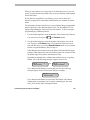
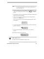
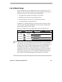
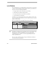
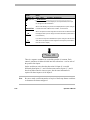
Sequence Programming Display
Before you begin programming the Sequence, you should have a basic
understanding of the fields shown during Sequence programming.
The following illustration provides an overview of the fields:
Column
1
Column
2
Evt
01
02
03
Cam
05
07
--
16
12
.
.
Column
3
Column
4
Act
Dur
View96 10
Patn3
05
View-- -View--
30
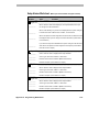
Events in a Sequence are divided into four columns:
column
1
column
2
4-8
“Evt” is the number of the event (1 through 16) within the
Sequence; this number determines the order of the events in the
sequence
“Cam” is the camera number on which the event was defined.
Operator's Manual
“Act” is the type of event (Quick View, Pattern, or fixed shot),
and number assigned to that event when it was originally
defined (1 through 96 for Views; 1 through 3 for Patterns; blank
for fixed shots).
column “Dur” is the amount of time, in seconds, that the event will
4
remain on the monitor before the Sequence switches to the next
event. This is the event's duration time. The maximum duration
time is 90 seconds.
When the fields in an event have dashes in them instead of values, the event
is not defined. Leaving an event undefined instructs the Sequence to skip that
event.
column
3
When the TOUCH TRACKER is in the menu/programming mode, the Tracker
Ball enables you to move the cursor around on the LCD. The blinking square
on the LCD indicates the cursor's location. Move the Tracker Ball up and
down to move the cursor from event to event. Move the Tracker Ball left and
right to move the cursor among the fields within an event.
When the define Sequence LCD is first displayed, the cursor appears in the
Cam field. This is where you indicate on which camera the first event to be
included in the Sequence was defined.
If the Sequence has not been defined, or if the first event in the Sequence was
not defined, the LCD looks like this:
Evt
01
Cam Act Dur
-- View-- --
If someone has already set up the Sequence, and the first event has been
defined, the information for the first event in the Sequence appears on the
LCD. For example:
Evt
01
Cam
7
Act Dur
View25 10
In the sample Sequence LCD (above), the first event is Quick View 25,
defined on camera 7, and its duration time is 10 seconds.
Defining Automatic System Functions
4-9
Defining the Sequence
Note
You must use the Main TOUCH TRACKER to define the Sequence.
The following procedure describes how to define the Sequence.
1. Press the Menu button on the keypad.
The TOUCH TRACKER is now in the menu/programming mode, and the
menu appears:
Define Sequence
Setup View
2. Press the appropriate button—zoom or focus—to select Define
Sequence.
If the Sequence has not been defined, or if the first event in the Sequence
was not defined, the LCD looks like this:
Evt
01
Cam Act Dur
-- View-- --
If someone has already set up the Sequence, and the first event has been
defined, the information for the first event in the Sequence appears on the
LCD. For example:
Evt
01
Cam
7
Act Dur
View25 10
3. Use the Tracker Ball to scroll to the event you want to define.
4. In the Cam field, indicate the camera on which this event was defined, or
the camera whose fixed shot you want to include. Use the number
buttons to enter the camera number.
4-10
Operator's Manual
5. In the Act field, indicate the type of Action, Quick View, Pattern, or
fixed shot you are specifying for this event. Press View to indicate a
Quick View or a fixed shot; press Pattern to indicate a Pattern.
6. Use the number buttons on the keypad to designate the specific number
of this Quick View or Pattern. This number was assigned to the Quick
View or Pattern when it was initially defined. If you want the Action to
be a fixed shot, press the Clear button.
7. In the Dur field, use the number buttons to enter the duration time, in
seconds, for this event. The maximum duration time is 90 seconds. The
duration time must be entered as two digits. For example, enter “05” for
5 seconds.
8. Use the Tracker Ball to scroll to the next event, and repeat Steps 4
through 7 for each event you want to include in this Sequence. You can
define up to 16 events. You can leave any event undefined by pressing
the Clear button when the cursor is in the Cam field for that event.
9. When you complete defining the Sequence, press the Menu button. This
returns the TOUCH TRACKER to the camera control mode.
Tip: A shortcut method for defining the Sequence is available. Press Menu,
then Seq to start sequence programming. Use the Tracker Ball to scroll to
the appropriate event number. Follow steps 4-9 above to assign the camera,
action, and duration to each event in the sequence.
Setting Up System Alarms
You can define up to 64 different alarms that can be triggered by the inputs
connected to domes at your facility. An alarm is triggered when one of these
inputs changes from its normal state to its abnormal state. For example, if the
input is a smoke detector, its normal state would be “not detecting smoke.”
However, when the smoke detector detects smoke, it changes to its abnormal
Defining Automatic System Functions
4-11
state, and this triggers an alarm. (Refer to your List of Inputs and Outputs in
Appendix A to determine the normal and abnormal state for each input.)
When an alarm is triggered, it can automatically call up one video action
(either a Quick View, a Pattern, or a fixed shot) and initiate one output. This
video action must have been defined for the same dome that the output is
connected to, and vice versa. Refer to the List of Inputs and Outputs in
Appendix A to determine which output devices are connected to which
domes. Refer to your List of Quick Views and List of Patterns in Appendix A
to determine which Quick Views and Patterns were defined for which domes.
It might be helpful for you to fill out the Setup Alarms Worksheet in
Appendix A before you begin setting up an alarm. On the Setup Alarms
Worksheet, you can calculate which inputs on which domes will trigger
which video action and output, if any. You can then refer to this worksheet
when you are actually setting up an alarm.
Tip: You must use the Main TOUCH TRACKER to set up Alarms.
The following procedure describes how to set up a system alarm.
1. Using the number buttons, enter the number of the camera for which you
are setting up the alarm. Then press
(the Camera button).
2. Press the Menu button.
The TOUCH TRACKER is now in the menu/programming mode, and the
menu appears:
Define Sequence
Setup View
4-12
Operator's Manual
3. Use the Tracker Ball to scroll through the menu selections until Alarm
Actions is displayed on the LCD.
Record Pattern
Alarm Actions
4. Press the appropriate button—zoom or focus—to select Alarm Actions.
The information for that camera's first alarm input appears on the LCD.
When you set up an alarm, you will indicate which Quick View, Pattern,
or fixed shot will be called up when the alarm is triggered. You will also
indicate which output initiates when this alarm is triggered. The video
action and the output must be associated with the same dome.
A sample setup alarm LCD is shown here.
Cam12/1 => Cam7
View96 Out3
If an alarm input has not been set up, the fields will have dashes in them. A
setup alarm LCD contains the following information:
1
This is the dome and
input that will trigger an
alarm when a change in
state is detected.
2
This is the dome whose
video appears on the
monitor when the alarm
occurs.
Cam12/1 => Cam7
View96 Out3
3
This is the specific Quick View or
Pattern that appears when the
alarm is triggered. If there is no
number in this field, this indicates
a fixed shot.
Defining Automatic System Functions
4
This is the specific output
that initiates when the
alarm is triggered.
4-13
In this sample alarm, input 1 on camera 12 is the specific input that will
trigger the alarm. The alarm input, for example, could be a motion
detector that triggers an alarm when it senses motion. When this alarm is
triggered, Quick View 96 on camera 7 appears on the monitor. In
addition, output 3 on the same camera initiates automatically. The output
might be, for example, a light that turns on when the alarm is triggered.
Even though you can only see the information for one alarm input at a
time, each camera can have four alarm inputs.
When the TOUCH TRACKER is in the menu/programming mode, the
Tracker Ball enables you to move the cursor around on the LCD. The
blinking square on the LCD indicates the cursor's location. Move the
Tracker Ball left and right to move the cursor among the fields on the
LCD.
5. When the setup alarm LCD is first displayed, the cursor is in the Cam
field for input 1 of the camera you indicated.
Is this the alarm input that you want to configure? If so, continue with
Step 6 now.
If this is not the alarm input you want to configure, use the Tracker Ball
to scroll through the available inputs until the appropriate input appears
in the input field.
6. In the Cam field, indicate the camera whose Quick View, Pattern, or fixed
shot appears when this alarm is triggered. This is the same camera whose
output initiates when the alarm is triggered. Use the number buttons on
the keypad to enter the camera number.
7. Move the Tracker Ball to the right move the cursor to the next field.
8. Choose one of the following:
•
4-14
Do you want a Quick View to be displayed when this alarm is
triggered? If so, use the number buttons to indicate the specific
Quick View (1 - 96).
Operator's Manual
•
Do you want a Pattern to be displayed when this alarm is
triggered? If so, press the Pattern button, and then use the
number buttons to indicate the specific Pattern (1 - 3).
•
Do you want a fixed shot to be displayed when this alarm is
triggered? If so, press the View button, but do not enter any
number in this field. When this alarm is triggered, you will see
video of wherever the camera (that you indicated in Step 6) is
currently pointing.
9. Move the Tracker Ball to the right. In the Out field, indicate the specific
output that initiates when this alarm is triggered. Use the number buttons
to enter the number. Remember, this output must be connected to the
camera you picked in Step 6.
If you do not want an output to initiate, leave this field blank.
10. Choose one of the following:
•
Do you want to set up another alarm input for this camera? If
so, use the Tracker Ball to scroll through the available inputs
until the appropriate input appears in the input field. Then repeat
Steps 6 through 8.
•
Do you want to set up an alarm for another camera? If so, press
the Next button on the keypad until the appropriate camera
number appears in the Alarm Cam field. Then, repeat Steps 5
through 9.
•
Are you finished setting up alarms for now? If so, press the
Menu button. This returns the TOUCH TRACKER to the camera
control mode.
SpeedDome LT Auto Pan Programming
The Auto Pan is a special feature supported by SpeedDome LT only. It
allows you program a smooth side-to-side camera pan of an area. The
SpeedDome LT does not allow you to program the same types of Patterns
Defining Automatic System Functions
4-15
that other domes support. Instead, use Pattern programming to set the Auto
Pan function.
Auto Pan Programming Limitations
Keep the following limitations in mind when programming the SpeedDome
LT Auto Pan feature:
•
Although it appears to have three Patterns available to program, you
can only program the Auto Pan feature for Pattern 1.
•
Any extraneous movements made during the Auto Pan programming
will be ignored when the programming is complete. Once the end
point of the Auto Pan is set, the result will be a smooth pan between
the start point and the end point of the Auto Pan.
•
Do not attempt to create an Auto Pan that is greater than one
revolution (360º) of the SpeedDome LT. The dome will accept this
pattern during programming; however, it will not work when you
attempt to run the pattern. The starting point and the ending point
must be less than one revolution of the SpeedDome for the Auto Pan
to work properly.
•
If you attempt to program Pattern 2 or 3 for the dome, the system
will take you through the motions of the programming. However, the
new Auto Pan will not be saved. Do not attempt to program more
than one Auto Pan per SpeedDome LT.
•
If you need to re-program the Auto Pan for the dome, you must
select Pattern 1. Selecting another available Pattern number will not
change the previously programmed Auto Pan.
To program the Auto Pan for SpeedDome LT, do the following:
4-16
Operator's Manual
Note
You must use the Main TOUCH TRACKER to define the Auto
Pan for SpeedDome LT.
1. Using the number buttons, enter the number of the SpeedDome LT for
which you are defining the Auto Pan. Then press
button).
(the Camera
2. Pan and tilt the camera to the starting point of the Pattern, and then zoom
and focus the camera accordingly.
3. When you have the perfect “starting point” picture displayed on the
monitor, press the Menu button.
The TOUCH TRACKER is now in the menu/programming mode, and the
menu appears:
Define Sequence
Setup View
4. Use the Tracker Ball to scroll through the menu selections until Record
Pattern is displayed.
Record Pattern
Alarm Actions
5. Press the appropriate button—zoom or focus—to select Record
Pattern.
The following prompt appears on the LCD:
Cam 3
Enter Patrn#?
IMPORTANT
The Auto Pan must be programmed for Pattern 1 only.
Defining Automatic System Functions
4-17
6. Press the number 1 on the keypad.
The following message appears on the LCD:
Record Pattern 1
Finish w <Next>
7. The Auto Pan is now being recorded. Any extraneous up or down
movement will be ignored when programming the Auto Pan.
If you pressed an invalid number (any number greater than 3), the TOUCH
TRACKER will beep and the system will not allow you to program the
Pattern. If this happens, simply press a valid number and continue with
this procedure.
8. Move the camera until you see end point for the Auto Pan you are
programming. Keep in mind this end point must be less than one full
revolution of the dome.
9. When you see the end point, press the Next button.
The following message appears on the LCD:
Cam 3
Pattern Saved
The TOUCH TRACKER automatically returns to the camera control mode.
In the List of Patterns (in Appendix A of this manual), make a record of
the Auto Pan that you just defined, including a brief description of the
Auto Pan.
To test the Auto Pan that was programmed, press 1, then Pattern. The
Auto Pan will run continuously until a camera command, such as tilt or
focus, is issued.
4-18
Operator's Manual
C H A P T E R
5
A
B
Pe
el
Inf
Me
nu
o
C
1
Ou On
tpu
t
Off
2
D
3
4
Clea
r
5
Iris
Fli
6
7
Clo
se
8
Op
en
0
p
Vie
w
Pa
9
tte rn
Re
pea
Pa
tte rn t
Seq
Pre
v iou
s
Next
TOUCH TRACKER Utilities
This chapter describes the utilities available for your system. These utilities
include language settings, alarm acknowledgment settings, resetting domes,
and ID code display.
In This Chapter
•
•
•
•
•
•
•
•
•
Selecting a Language
Designating Main Versus Call TOUCH TRACKER
Toggling Automatic/Manual Alarm Acknowledgment
Adjusting LCD Brightness
Turning Key Click On / Off
Adjusting Key Click Volume
Resetting the Dome
Displaying a Dome's ID Code
Special Utilities
Selecting a Language
Choose which language you would like the TOUCH TRACKER LCD text to be
displayed in:
•
•
•
•
English
French
Spanish
German
•
•
•
•
Dutch
Italian
Japanese
Portuguese
•
•
Swedish
Hungarian
1. Press the Menu button on the keypad to display the menu.
2. Use the Tracker Ball to scroll through the menu items and press the
appropriate button— zoom or focus—to choose Select Language.
The LCD displays the list from which you can choose a language.
English
Francais
The list only displays two choices at any one time.
3. Use the Tracker Ball to scroll through the language selections, and press
the appropriate button—zoom or focus—to select the correct language.
The TOUCH TRACKER resets and comes back up in the selected language. The
TOUCH TRACKER is again in the camera control mode.
Designating Main Versus Call TOUCH TRACKER
If your facility has two TOUCH TRACKERs installed, one was installed as the
Main TOUCH TRACKER and the other as the Call TOUCH TRACKER. You
cannot designate both TOUCH TRACKERs as Main or Call; this will cause a
communication error.
The chart on the following page outlines the features available to the Main
TOUCH TRACKER. It also shows the limited feature set of the Call TOUCH
TRACKER.
5-2
Operator’s Manual
TOUCH TRACKER
Functions
Main
TOUCH TRACKER
Designate which external unit the
system is connected to (quad
splitter, multiplexer, POS/EM,
PC, no unit)
ü
Select display mode (2x2, 3x3,
4x4, or full-screen format
ü
Select a camera
ü
ü
ü
ü
Manually control a camera (pan,
tilt, zoom, focus, iris)
Flip a SpeedDome
Initiate automatic system
functions (Quick Views, Patterns,
outputs)
Run the Sequence
ü
Clear alarms
ü
Define automatic system
functions (Quick Views, Patterns,
Sequence, alarms)
ü
Reset a SpeedDome
ü
ü
ü
ü
Select language for TOUCH
TRACKER text
Designate Main vs. Call TOUCH
TRACKER
Adjust LCD brightness, key click
volume, turn key click on / off
Call
TOUCH TRACKER
ü
ü
ü
ü
ü
ü
ü
ü
As your needs change, you may want to switch the Main and Call TOUCH
TRACKERs.
TOUCH TRACKER Utilities
5-3
IMPORTANT
The following procedure describes how to toggle the current Main and Call
TOUCH TRACKERs. Before you begin this procedure, you must know which
TOUCH TRACKER you want to designate the Main, and which one you want
as the Call. You can distinguish between the two TOUCH TRACKERs by
looking at their menus. The Main TOUCH TRACKER contains all of the menu
items, while the Call TOUCH TRACKER has a limited menu selection.
If you want to toggle the functionality of the TOUCH TRACKERs, first you
must do so on the current the Main TOUCH TRACKER.
1. On the Main TOUCH TRACKER, press the Menu button to display the
menu.
2. Scroll through the menu items and press the appropriate button—zoom or
focus—to select Tog Primary/2nd.
The LCD displays the following prompt:
Primary Unit
Change w <Next>
3. Press the Next button to designate this the Call TOUCH TRACKER.
4. Press the Menu button to exit the menu/programming mode on this
TOUCH TRACKER.
5. On the other TOUCH TRACKER, press the Menu button to display the
menu.
6. Scroll through the menu items and then press the appropriate button—
zoom or focus—to select Tog Primary/2nd.
5-4
Operator’s Manual
The LCD displays the following prompt:
Secondary Unit
Change w <Next>
7. Press the Next button to designate this the Main TOUCH TRACKER.
8. Press the Menu button to exit the menu/programming mode on this
TOUCH TRACKER.
The TOUCH TRACKER resets and starts in the camera control mode.
Toggling Automatic/Manual Alarm Acknowledgment
The default setting for the TOUCH TRACKER is to automatically clear alarms
after 60 seconds. You can, however, change this to have alarms manually
acknowledged by the system operators.
To toggle the Automatic/Manual Alarm Acknowledgment function, do the
following:
1. Press the D button.
If Automatic Alarm Acknowledgment is enabled, you will see the
following message:
Auto Ack Alarm
If Manual Alarm Acknowledgment is enabled, you will see the
following:
Manual Ack Alarm
2. Press D again to change alarm acknowledgment to the preferred type.
3. Press Clear to return the LCD to camera control mode.
TOUCH TRACKER Utilities
5-5
Adjusting LCD Brightness
If you find it difficult to see items displayed on the Touch Tracker LCD, you
may want to adjust its brightness setting.
1. Press Menu to display the LCD menu.
2. Use the Tracker Ball to scroll through the menu items. When you see Adj
Backlighting, press Zoom or Focus to select.
3. Press Previous or Next to change the setting.
•
Press Previous to make the backlighting dimmer.
•
Press Next to make the backlighting brighter.
4. When finished, press Menu to return to camera control mode.
Turning Key Click On / Off
If you want to enable or disable the click sound that is made when you press
buttons on the Touch Tracker, do the following:
1. Press Menu to display the LCD menu.
2. Use the Tracker Ball to scroll through the menu items. When you see Key
Click On/Off, press Zoom or Focus to select.
3. Press Next to change the setting.
•
If the key click is enabled, the following appears on the LCD screen:
Keyclick ON
<- <NEXT>
•
->
If the key click is disabled, the following appears on the LCD screen:
Keyclick OFF
<- <NEXT> ->
4. When finished, press Menu to return to camera control mode.
5-6
Operator’s Manual
Adjusting Key Click Volume
To adjust the volume of the key click sound, do the following:
1. Press Menu to display the LCD menu.
2. Use the Tracker Ball to scroll through the menu items. When you see Adj
Keyclick Vol, press Zoom or Focus to select.
3. Press Previous or Next to change the setting.
•
Press Previous to make the volume softer.
•
Press Next to make the volume louder.
4. When finished, press Menu to return to camera control mode.
Resetting the Dome
If you find that one of the SpeedDome Series of cameras is not responding as
expected to TOUCH TRACKER commands, you should reset the dome. The
following procedure describes how to reset the dome.
1. Using the number buttons, enter the number of the camera you want to
reset (for example, camera 5) and then press
button).
(the Camera
2. Press the Menu button to display the menu.
3. Use the Tracker Ball to scroll through the menu items and press the
appropriate button—zoom or focus—to select Reset Dome.
The LCD displays the following message:
Cam 5
+
Reset In Process
The SpeedDome is inoperable while it is resetting. Once the SpeedDome
completes the reset, the TOUCH TRACKER returns to the camera control mode.
TOUCH TRACKER Utilities
5-7
Displaying a Dome's ID Code
The following procedure describes how to display the ID code for the
currently selected dome. The ID code may be useful when diagnosing a
problem.
1. Using the number buttons, enter the number of the dome whose ID code
you want to display (for example, camera 3) and then press
Camera button).
(the
2. Press the Info button on the keypad.
The LCD displays the following prompt:
Cam 3
F 0701-0081-0134
Notice the “F” prefix in front of the ID code; this indicates that it applies
to the dome's Flash PROM.
3. Press the Info button again to display the dome's EEPROM ID code.
Cam 3
E 0701-0079-0310
Notice the “E” prefix in front of the ID code; this indicates that it applies
to the dome's EEPROM.
4. Each time you press the Info button, you alternate between the Flash
PROM and the EEPROM ID codes.
5. Press the Clear button on the keypad.
The TOUCH TRACKER is again in the camera control mode.
Special Utilities
Although Adjust V-phase, Show Sys Info, and Ping Dome/TTR are
considered to be utility items on the menu, these utilities are reserved for use
5-8
Operator’s Manual
by authorized service personnel. However, they may be performed by you, in
conjunction with an authorized service provider over the phone. There are no
procedures in this documentation describing their use.
TOUCH TRACKER Utilities
5-9
NOTES:
5-10
Operator’s Manual
A P P E N D I X
A
A
B
Pe
el
Inf
Me
nu
o
C
1
Ou On
tpu
t
Off
2
D
3
4
Clea
r
5
Iris
Fli
6
7
Clo
se
8
Op
en
0
p
Vie
w
Pa
9
tte rn
Re
pea
Pa
tte rn t
Seq
Pre
v iou
s
Next
Programming Worksheets
This Appendix contains worksheets that will make the task of programming
your system a great deal easier. There are five different kinds of worksheets
included in this appendix.
•
The List of Quick Views worksheet allows you to keep a record of the
Quick Views you have defined for your facility. This information
includes the Quick View number, the camera number, camera type, and a
brief description of each Quick View.
•
The List of Patterns worksheet allows you to keep a record of the
Patterns you have defined for your facility. This information includes the
Pattern number, the camera number, camera type, and a brief description
of each Pattern.
Note
A-2
•
The List of Inputs and Outputs worksheet allows you to keep a record of
those inputs and outputs that have been configured at your facility, along
with their associated information.
•
The Setup Sequence worksheet allows you to determine which Quick
Views, Patterns, and Fixed shots will be included in the Sequence before
you actually begin setting up the Sequence.
•
The Setup Alarms worksheet allows you to calculate all of the
information associated with setting up alarms before you actually begin
defining the alarms.
It is strongly recommended that you make photocopies of the different kinds
of worksheets in this Appendix before you actually begin filling them out. It
is likely that the Sequence and the alarms (and the Quick Views and Patterns
that they are comprised of) will change over time. We have provided only a
minimal number of these worksheets. Make sure you always have extra
copies available.
Operator's Manual
List of Quick Views
We recommend that, as you define Quick Views to meet the needs of your
facility, you then record those Quick Views in this Appendix. That way, you
will have an easy way to access the following information:
•
The approximate location of the domes at your facility
•
Which domes have Quick Views defined for them
•
How many Quick Views have been defined for each dome
•
A brief description of each Quick View
In addition, by recording the Quick Views that you have defined, it will be
easier for you to determine which Quick Views you want to include when
setting up the Sequence and the alarms.
Here is an example of how you might fill out your list of Quick Views:
Note
Dome #:___7___
Dome Type: Ultra
Location: ____lobby__________
View Number: 1__
Description:
View Number: __2__
Description: _____Receptionist Desk
View Number: __3__
Description: ______Front Hallway___________________________
View Number: __4__
Description: _____Waiting Room___________________________
Lobby___________________________________
There are two types of worksheets provided for Quick Views. SpeedDome
Ultra III and newer domes support up to 96 views. The worksheet appearing
on page A-4 provides 22 spaces for documenting views for SpeedDome
Ultra III and newer domes. Make multiple copies of this page for each
SpeedDome Ultra III or newer dome installed at your facility. Other domes
support up to four views. The worksheet appearing on page A-5 provides
space for documenting four views for four domes. Make multiple copies of
this worksheet for documenting other domes installed at your facility.
Appendix A: Programming Worksheets
A-3
List of Quick Views - (Make Copies of this page for SpeedDome Ultra III and newer domes.)
A-4
Dome #:________
Dome Type: _______
Location: __________________
View Number: _____
Description: ________________________________________________
View Number: _____
Description: ________________________________________________
View Number: _____
Description: ________________________________________________
View Number: _____
Description: ________________________________________________
View Number: _____
Description: ________________________________________________
View Number: _____
Description: ________________________________________________
View Number: _____
Description: ________________________________________________
View Number: _____
Description: ________________________________________________
View Number: _____
Description: ________________________________________________
View Number: _____
Description: ________________________________________________
View Number: _____
Description: ________________________________________________
View Number: _____
Description: ________________________________________________
View Number: _____
Description: ________________________________________________
View Number: _____
Description: ________________________________________________
View Number: _____
Description: ________________________________________________
View Number: _____
Description: ________________________________________________
View Number: _____
Description: ________________________________________________
View Number: _____
Description: ________________________________________________
View Number: _____
Description: ________________________________________________
View Number: _____
Description: ________________________________________________
View Number: _____
Description: ________________________________________________
Operator's Manual
List of Quick Views - (Make copies of this page for SpeedDome & SpeedDome Ultra)
Dome #:________
Dome Type: _______
View Number: _____
Description: ______________________________________________
View Number: _____
Description: ______________________________________________
View Number: _____
Description: ______________________________________________
View Number: _____
Description: ______________________________________________
Appendix A: Programming Worksheets
Location: __________________
Location: _________________
Location: _________________
Location: _________________
A-5
List of Patterns
We recommend that, as you define Patterns to meet the needs of your facility,
you then record those Patterns in this Appendix. That way, you will have an
easy way to access the following information:
•
the approximate location of the domes at your facility
•
which domes have Patterns defined for them
•
how many Patterns have been defined for each dome
•
a brief description of each Pattern
In addition, if you record the Patterns that you have defined, it will be easier
for you to determine which Patterns you want to include when you set up the
Sequence and the alarms.
Here is an example of how you might fill out your list of Patterns:
Note
Dome
Number:__12__
Dome
Type: SpeedDome
Pattern Number: _1_
Description: ___Parking Lot________________________________
Pattern Number: _2_
Description: ___Emergency Exit____________________________
Pattern Number: _3_
Description: ____Loading Dock 1___________________________
Location:
Loading Dock_______
SpeedDome, SpeedDome Ultra, SpeedDome Ultra II, and SpeedDome Ultra
III support up to 3 patterns. SpeedDome LT does not support pattern
programming; however, Pattern 1 is used for programming the auto pan
feature of SpeedDome LT.
Be sure to make a sufficient number of copies of the Pattern worksheet to
document all patterns programmed.
A-6
Operator's Manual
List of Patterns - (Make copies of the worksheet to support all domes installed)
Dome #:___
Dome Type: _____
Pattern #: ___
Description: ________________________________________________
Pattern #: ___
Description: ________________________________________________
Pattern #: ___
Description: ________________________________________________
Dome #:___
Dome Type: _____
Pattern #: ___
Description: ________________________________________________
Pattern #: ___
Description: ________________________________________________
Pattern #: ___
Description: ________________________________________________
Dome #:___
Dome Type: _____
Pattern #: ___
Description: ________________________________________________
Pattern #: ___
Description: ________________________________________________
Pattern #: ___
Description: ________________________________________________
Dome #:___
Dome Type: _____
Pattern #: ___
Description: ________________________________________________
Pattern #: ___
Description: ________________________________________________
Pattern #: ___
Description: ________________________________________________
Dome #:___
Dome Type: _____
Pattern #: ___
Description: ________________________________________________
Pattern #: ___
Description: ________________________________________________
Pattern #: ___
Description: ________________________________________________
Appendix A: Programming Worksheets
Location: _____________________
Location: _____________________
Location: _____________________
Location: _____________________
Location: _____________________
A-7
List of Patterns - (Make copies of the worksheet to support all domes installed)
A-8
Dome #:___
Dome Type: _____
Location: _____________________
Pattern #: ___
Description: ________________________________________________
Pattern #: ___
Description: ________________________________________________
Pattern #: ___
Description: ________________________________________________
Dome #:___
Dome Type: _____
Pattern #: ___
Description: ________________________________________________
Pattern #: ___
Description: ________________________________________________
Pattern #: ___
Description: ________________________________________________
Dome #:___
Dome Type: _____
Pattern #: ___
Description: ________________________________________________
Pattern #: ___
Description: ________________________________________________
Pattern #: ___
Description: ________________________________________________
Dome #:___
Dome Type: _____
Pattern #: ___
Description: ________________________________________________
Pattern #: ___
Description: ________________________________________________
Pattern #: ___
Description: ________________________________________________
Dome #:___
Dome Type: _____
Pattern #: ___
Description: ________________________________________________
Pattern #: ___
Description: ________________________________________________
Pattern #: ___
Description: ________________________________________________
Location: _____________________
Location: _____________________
Location: _____________________
Location: _____________________
Operator's Manual
List of Inputs and Outputs
This section lists those inputs and outputs (auxiliaries) that have been
configured at your facility. It contains the following information:
•
which domes have inputs and outputs configured
•
a brief description of the inputs and outputs that have been configured
•
the “normal” and “abnormal” state for each input
• the “on” and “off” state for each output
A list of the configured inputs and outputs will make it easier for you to
toggle the state of the outputs, as described in Chapter 3, “Controlling
Cameras and Their Outputs.” It will also make it easier for you to set up your
system alarms and interpret those alarms when they appear on the LCD.
Here is an example of how to fill out the inputs/outputs list:
Dome
Number:__8__
Dome
Type: __Ultra__
Location: _North Entrance_
Description
Input 1:__Smoke detector lobby_______
Normal
Abnormal
No Smoke
Smoke
Input 2:
Motion detector___________
No Motion
Motion
Input 3:
Twilight Sensor______________
Daylight
Dusk
Input 4:_______________________
_____________
_____________
Description
On State
Off State
Output 1:
Light Service Center________
On
Off
Output 2:
North Gate_________________
Closed
Open
Output 3:Main Office door_____________
Locked
Unlocked
Output 4:______________________
_____________
_____________
Appendix A: Programming Worksheets
A-9
List of Inputs and Outputs - (Make copies of the worksheet to support all domes)
Dome
Number:______
Dome
Type: ________
Location: _____________________
Description
Normal
Abnormal
Description
On State
Off State
Input 1:
Input 2:
Input 3:
Input 4:
Output 1:
Output 2:
Output 3:
Output 4:
Dome
Number:______
Dome
Type: ________
Location: _____________________
Description
Normal
Abnormal
Description
On State
Off State
Input 1:
Input 2:
Input 3:
Input 4:
Output 1:
Output 2:
Output 3:
Output 4:
A-10
Operator's Manual
List of Inputs and Outputs - (Make copies of the worksheet to support all domes)
Dome
Number:______
Dome
Type: ________
Location: _____________________
Description
Normal
Abnormal
Description
On State
Off State
Input 1:
Input 2:
Input 3:
Input 4:
Output 1:
Output 2:
Output 3:
Output 4:
Dome
Number:______
Dome
Type: ________
Location: _____________________
Description
Normal
Abnormal
Description
On State
Off State
Input 1:
Input 2:
Input 3:
Input 4:
Output 1:
Output 2:
Output 3:
Output 4:
Appendix A: Programming Worksheets
A-11
Setup Sequence Worksheet
Fill out the Setup Sequence Worksheet before you begin actually setting up
the Sequence. This worksheet enables you to determine the following:
•
which events will be included in the Sequence
•
The camera on which each event was defined
•
the kind of event (Quick View, Pattern, or fixed shot)
•
the specific number assigned to the event (this number was determined
when the event was initially defined
•
the duration time for each event
Once you fill out this worksheet, use it to help you set up the Sequence.
The following is a sample Setup Sequence Worksheet. If you set up this
sample event within the Sequence, the LCD will look like the one illustrated
below the worksheet.
Event #1
___4_____
Number of camera whose video will be displayed in this event?
____View___
Action Type (Quick View, Pattern, or Fixed Shot).
___2_____
Action Number (Leave blank if Action Type is fixed shot).
___10____
Duration time (in seconds) for this event
Evt Cam Act Dur
01
4 View96 10
A-12
Operator's Manual
Setup Sequence Worksheet- (Make copies of the worksheet to support all events)
Event #_______
__________ Number of camera whose video will be displayed in this event?
__________
Action Type (Quick View, Pattern, or Fixed Shot).
__________
Action Number (Leave blank if Action Type is fixed shot).
__________
Duration time (in seconds) for this event
Event #______
__________ Number of camera whose video will be displayed in this event?
__________
Action Type (Quick View, Pattern, or Fixed Shot).
__________
Action Number (Leave blank if Action Type is fixed shot).
__________
Duration time (in seconds) for this event.
Event #_____
__________ Number of camera whose video will be displayed in this event?
__________
Action Type (Quick View, Pattern, or Fixed Shot).
__________
Action Number (Leave blank if Action Type is fixed shot).
__________
Duration time (in seconds) for this event.
Event #_______
__________ Number of camera whose video will be displayed in this event?
__________
Action Type (Quick View, Pattern, or Fixed Shot).
__________
Action Number (Leave blank if Action Type is fixed shot).
__________
Duration time (in seconds) for this event.
Appendix A: Programming Worksheets
A-13
Setup Sequence Worksheet- (Make copies of the worksheet to support all events)
Event #______
__________ Number of camera whose video will be displayed in this event?
__________
Action Type (Quick View, Pattern, or Fixed Shot).
__________
Action Number (Leave blank if Action Type is fixed shot).
__________
Duration time (in seconds) for this event.
Event #_______
__________ Number of camera whose video will be displayed in this event?
__________
Action Type (Quick View, Pattern, or Fixed Shot).
__________
Action Number (Leave blank if Action Type is fixed shot).
__________
Duration time (in seconds) for this event.
Event #_______
__________ Number of camera whose video will be displayed in this event?
__________
Action Type (Quick View, Pattern, or Fixed Shot).
__________
Action Number (Leave blank if Action Type is fixed shot).
__________
Duration time (in seconds) for this event.
Event #_______
__________ Number of camera whose video will be displayed in this event?
A-14
__________
Action Type (Quick View, Pattern, or Fixed Shot).
__________
Action Number (Leave blank if Action Type is fixed shot).
__________
Duration time (in seconds) for this event.
Operator's Manual
Setup Alarms Worksheet
Fill out the Setup Alarms Worksheet before you begin actually setting up an
alarm. This worksheet enables you to determine the following:
•
which inputs on which domes will trigger an alarm when their state
changes from normal to abnormal (remember, the normal and abnormal
states for each input are listed on the List of Inputs & Outputs)
•
the camera whose video will be displayed and whose output will be
initiated when the alarm is triggered
•
the kind of video action that will take place when the alarm is triggered
(either a Quick View, a Pattern, or a fixed shot)
•
the specific number assigned to the Quick View or Pattern that will be
displayed when the alarm is triggered
•
the specific number assigned to the output, if any, that will be initiated
when the alarm is triggered
On the following page is a sample Setup Alarms Worksheet. If you set up
this sample alarm, the LCD will look like the one illustrated below the
worksheet.
Once you fill out this worksheet, use it to help you set up the system alarms.
These worksheets can also help you to interpret what appears on the LCD
when the system is in the alarm mode.
Appendix A: Programming Worksheets
A-15
Dome
Number: 12
Dome
Type: Ultra
Location: Accessories
Input #1: ____Smoke Detector_______________________________________
Which camera's video will be displayed, and output initiated, when input
7
#1 changes to its abnormal state?
Which of the following do you want to be displayed when input #1 changes
Quick View
to its abnormal state: a Quick View, a Pattern, or a fixed shot?
What is the specific number assigned to the Quick View or Pattern that will
__96__
be displayed when input #1 changes to its abnormal state? (Leave blank if
it is a fixed shot.)
If you want an output to be initiated when input #1 changes to its abnormal
__3__
state, what is the specific number assigned to that output? (Leave blank if
there will not be an output.)
Cam12/1
View96
Cam7
Out3
There is a separate worksheet for each of the possible 16 cameras. Each
camera's worksheet is further divided into four subsections—one for each of
the possible four inputs.
On the worksheets, notice that the subsection for Input #1 is worded
differently than Inputs 2, 3, and 4 for that same camera. Inputs 2, 3, and 4
have been abbreviated to conserve space, but the same information is
required for those inputs as is for Input #1.
Note
A-16
Be sure to make a sufficient number of copies of the Setup Alarms worksheet
to document all alarms configured.
Operator's Manual
Setup Alarms Worksheet- (Make copies of the worksheet to support all alarms)
Dome
Number: ___
Dome
Type: _______
Location: ____________________________
Input #1: _________________________________________________
Which camera's video will be displayed, and output initiated, when input
________
#1 changes to its abnormal state?
Which of the following do you want to be displayed when input #1 changes
________
to its abnormal state: a Quick View, a Pattern, or a fixed shot?
What is the specific number assigned to the Quick View or Pattern that will
________
be displayed when input #1 changes to its abnormal state? (Leave blank if
it is a fixed shot.)
If you want an output to be initiated when input #1 changes to its abnormal
________
state, what is the specific number assigned to that output? (Leave blank if
there will not be an output.)
Input #2: _________________________________________________
________
Which camera's video is displayed and output initiated?
________
Action Type: Quick View, Pattern, or fixed shot?
________
Number of Quick View or Pattern? (Blank for fixed shot)
________
Number of Output? (Leave blank if no output.)
Input #3: _________________________________________________
________
Which camera's video is displayed and output initiated?
________
Action Type: Quick View, Pattern, or fixed shot?
________
Number of Quick View or Pattern? (Blank for fixed shot)
________
Number of Output? (Leave blank if no output.)
Input #4: _________________________________________________
________
Which camera's video is displayed and output initiated?
________
Action Type: Quick View, Pattern, or fixed shot?
________
Number of Quick View or Pattern? (Blank for fixed shot)
________
Number of Output? (Leave blank if no output.)
Appendix A: Programming Worksheets
A-17
Setup Alarms Worksheet- (Make copies of the worksheet to support all alarms)
Dome
Number: ___
Dome
Type: _______
Location: ____________________________
Input #1: _________________________________________________
Which camera's video will be displayed, and output initiated, when input
_________
#1 changes to its abnormal state?
Which of the following do you want to be displayed when input #1 changes
_________
to its abnormal state: a Quick View, a Pattern, or a fixed shot?
What is the specific number assigned to the Quick View or Pattern that will
_________
be displayed when input #1 changes to its abnormal state? (Leave blank if
it is a fixed shot.)
If you want an output to be initiated when input #1 changes to its abnormal
_________
state, what is the specific number assigned to that output? (Leave blank if
there will not be an output.)
Input #2: _________________________________________________
_________
Which camera's video is displayed and output initiated?
_________
Action Type: Quick View, Pattern, or fixed shot?
_________
Number of Quick View or Pattern? (Blank for fixed shot)
_________
Number of Output? (Leave blank if no output.)
Input #3: _________________________________________________
_________
Which camera's video is displayed and output initiated?
_________
Action Type: Quick View, Pattern, or fixed shot?
_________
Number of Quick View or Pattern? (Blank for fixed shot)
_________
Number of Output? (Leave blank if no output.)
Input #4: _________________________________________________
_________
Which camera's video is displayed and output initiated?
_________
Action Type: Quick View, Pattern, or fixed shot?
_________
Number of Quick View or Pattern? (Blank for fixed shot)
_________
Number of Output? (Leave blank if no output.)
A-18
Operator's Manual
A P P E N D I X
B
A
B
Pe
el
Inf
Me
nu
o
C
1
Ou On
tpu
t
Off
2
D
3
4
Clea
r
5
Iris
Fli
6
7
Clo
se
8
Op
en
0
p
Vie
w
Pa
9
tte rn
Re
pea
Pa
tte rn t
Seq
Pre
v iou
s
Next
Software License Agreement
By using View Manager 16 Plus software, you accept the terms and
conditions of this license agreement. Read this license agreement carefully.
SOFTWARE LICENSE AGREEMENT
1. General. Software is being licensed to the Customer pursuant to the
following terms and conditions, which supplement any purchase or lease
agreement (the "Equipment Agreement") between Customer and
Sensormatic Electronics Corporation ("SEC"). By accepting receipt of, or
by using, such Software, the Customer agrees to be bound by the terms
of this Software License Agreement (the "License Agreement"). The
term “Software” means all computer programs, instructions, data and
databases, in any form or on any media, supplied by SEC (or its
suppliers) to Customer and all current and future versions, revisions,
updates, upgrades and new releases thereof. Except as otherwise
provided in this License Agreement, the terms and conditions of the
Equipment Agreement apply to the Software, the related technical and
user manuals ("Documentation") and the license provided herein.
2. License. SEC licenses the Software and the Documentation to Customer,
for the license fee(s) set forth (or included in the product prices set forth)
in the Equipment Agreement and subject to the terms and conditions of
this License Agreement. The license is non-exclusive and is limited by
the terms of this License Agreement. Customer may not transfer the
license except to a party to whom the equipment is transferred and then
only with the written consent of SEC. The Software and Documentation
are being licensed and not sold or leased to Customer. SEC or its
suppliers who have authorized SEC to sublicense certain of the Software
and Documentation retain ownership of the Software and
Documentation. The Software is being licensed for use only on (i) a
single computer (A) owned or leased by Customer and identified in the
Equipment Agreement or (B) otherwise identified in the Documentation
as compatible with the Software, or (ii) a back-up machine if and so long
as such computer becomes temporarily inoperable.
3. Term. The term of the license is perpetual, except that it will terminate
automatically if Customer sells or otherwise disposes of the Software or
its related equipment or Customer breaches any provision of this License
Agreement or the Equipment Agreement. If the license terminates, SEC
will have the right to take possession of all copies of the Software and
B-2
Operator's Manual
Documentation in the possession of Customer or to require Customer to
destroy all such copies and certify such destruction in writing to SEC.
4. Ownership. Customer agrees and acknowledges that (i) SEC (or its
suppliers) is the sole owner of the Software and Documentation
(including all copies thereof, in whatever form or media, delivered to or
made by Customer) and all patent, copyright and other intellectual
property rights with respect thereto and (ii) the Software and
Documentation constitute valuable trade secrets, confidential information
and proprietary properties of SEC and its suppliers. Accordingly,
Customer agrees that it will have no rights in the Software or
Documentation other than those granted under this License Agreement
and agrees to abide by the restrictions on its use of the Software and
Documentation set forth in Section 5 of this License Agreement.
5. Use and Copies. Customer may use the Software and Documentation
only in conjunction with the other equipment identified in the Equipment
Agreement, as part of the access control, closed circuit television or other
security system being acquired from SEC and for Customer's internal
business purposes. SEC will furnish the Software to Customer solely in
object code form.
Customer may make up to 2 copies of the Software solely for back-up
and archival purposes. Customer will not remove or modify the
copyright and other proprietary notices and legends of SEC and its
suppliers contained in the Software and Documentation and will
reproduce all such notices and legends on all copies of the Software
made by Customer. Customer may not make copies of the
Documentation, but may obtain additional copies of the Documentation
from SEC at its established rates. Except as permitted above, copying of
the Software and Documentation is forbidden.
Customer will not sell, assign, sublicense or transfer this license or sell or
otherwise transfer the Software or Documentation (or any portion
thereof) to others. Customer will maintain the Software and
Documentation in confidence and not disclose any data or other
information contained in the Software or Documentation to any party,
except for Customer's employees and agents who require access to the
Appendix B: Software License Agreement
B-3
Software for the purposes of Customer's internal business and who use it
in accordance with the terms of this License Agreement. Customer will
not use the Software for the provision of time-sharing services to others.
Customer will not modify the Software or decompile, disassemble or
otherwise reverse engineer the Software and will not have the right to
create derivative works of the Software, including, without limitation,
translated or localized versions of the Software. Customer will not export
or re-export the Software or the Documentation or any portion thereof
without appropriate United States or foreign governmental licenses.
Customer will implement appropriate measures, such as the requirement
that employees and others permitted access to the Software enter into
appropriate non-disclosure agreements, to satisfy its obligations
hereunder and, generally, will treat the Software and Documentation with
the same degree of care and confidentiality which Customer provides for
its own confidential information. Customer acknowledges that it may be
held legally responsible for any copyright infringement or trade secret
violation that is caused, in whole or in part, by its failure to abide by the
terms of this License Agreement. Since unauthorized transfer, use or
disclosure of the Software and Documentation would diminish their
value to SEC and its suppliers, who would have no adequate remedy at
law if Customer breaches its obligations under this License Agreement,
SEC and its suppliers (who are direct and intended beneficiaries of this
License Agreement) will be entitled to injunctive relief, in addition to
such other remedies and relief that would be available to them in the
event of such a breach.
6. Limited Warranty; Limitation of Liability. The provisions of the
Equipment Agreement respecting maintenance and warranty will not
apply to the Software or the Documentation, unless specifically stated
otherwise and agreed to in writing by both parties. SEC's sole warranties
with respect to the Software and Documentation are that (i) SEC has title
to the Software and Documentation and/or the right to grant Customer
the license set forth in this License Agreement and (ii) the magnetic
media on which the Software is recorded is free from defects in materials
and workmanship under normal use. SEC's sole obligation under this
warranty will be to replace any defective media returned to it free of
B-4
Operator's Manual
charge. The period of this warranty will be 12 months from the date of
the Equipment Agreement (the “Warranty Period”).
EXCEPT AS SET FORTH IN THIS SECTION 6, SEC DISCLAIMS ANY
WARRANTY, EXPRESS OR IMPLIED, WITH RESPECT TO THE
SOFTWARE OR THE DOCUMENTATION OR THEIR OPERATION OR
USE, INCLUDING, WITHOUT LIMITATION, ANY IMPLIED
WARRANTY OF MERCHANTABILITY OR OF FITNESS FOR A
PARTICULAR PURPOSE OR USE. SOME STATES DO NOT ALLOW
THE EXCLUSION OF IMPLIED WARRANTIES, SO THE ABOVE
EXCLUSION DOES NOT APPLY IN SUCH STATES. THIS
WARRANTY GIVES YOU SPECIFIC LEGAL RIGHTS, AND YOU MAY
ALSO HAVE OTHER RIGHTS THAT VARY FROM STATE TO STATE.
SEC AND ITS SUPPLIERS, EMPLOYEES, AGENTS AND
FRANCHISEES WILL IN NO EVENT BE LIABLE FOR ANY
INCIDENTAL, CONSEQUENTIAL OR OTHER DIRECT OR INDIRECT
DAMAGES (FOR LOSS OF BUSINESS INFORMATION OR PROFITS
OR OTHERWISE) SUFFERED BY CUSTOMER, ANY OF ITS
EMPLOYEES OR AGENTS OR ANY OTHER PERSON ARISING OUT
OF OR IN CONNECTION WITH THE USE OR INABILITY TO USE THE
SOFTWARE OR THE DOCUMENTATION, OR THE MAINTENANCE
OR SUPPORT THEREOF, EVEN IF THEY HAVE BEEN ADVISED OF
THE POSSIBILITY OF SUCH DAMAGES. SEC neither assumes nor
authorizes any employee, agent or franchisee to assume for SEC any other
liability in connection with the license, use or performance of the Software or
Documentation.
Customer is solely responsible for the selection of the Software to achieve
customer’s intended results, for the conformity of the computer on which the
Software is run to SEC’s specifications or requirements and for the
maintenance of such computer in good working order and repair. SEC’s
suppliers do not warrant the Software, assume any liability regarding the use
of the Software or undertake to provide any maintenance, support or
information regarding the Software.
7. U.S. Government Restricted Rights. The Software and Documentation
are provided with restricted rights. Use, duplication or disclosure by the
U.S. Government is subject to restrictions as set forth in subparagraphs
Appendix B: Software License Agreement
B-5
(c)(1)(ii) of the Rights in Technical Data and Computer Software Clause
of Department of Defense Federal Acquisition Supplement (DFARS)
252.227-7013 or in subparagraph (g)(3)(i) of Federal Acquisition
Regulations (FAR) 52.227-14, Alternate III, as applicable.
8. Indemnity. SEC will defend and hold Customer harmless from any
claim, action, suit or proceeding brought against Customer to the extent
that it is based on a claim that the use of the Software, as such, in
accordance with this License Agreement and not as a result of the
combination thereof with any other article, computer software or process,
constitutes an infringement of any United States patent or copyright or
the violation of any trade secret, if SEC is notified thereof promptly after
its commencement and is given control of the defense thereof and any
negotiations for its settlement and full cooperation by Customer.
SEC will pay all damages and costs awarded against Customer in
connection with any such claim, except that SEC will not be liable for
any amounts paid under any compromise or settlement made without its
consent. If the Software is either claimed or held to infringe or violate
any patent or copyright, SEC may, at its sole option and expense, and
Customer will permit SEC to, procure for Customer the right to continue
using the Software or modify it so that it becomes non-infringing or
replace it with a non-infringing counterpart. If neither of such
alternatives is available on terms which are reasonable in SEC's
judgment, Customer will return all copies of the Software and
Documentation in the possession of Customer to SEC, at SEC's request,
and SEC will refund a reasonable portion of the license fees paid by
Customer to SEC. This Section 8 sets forth SEC's entire liability
regarding infringement and the like.
B-6
Operator's Manual
A
B
Pe
el
Inf
Me
nu
o
C
1
Ou On
tpu
t
Off
2
D
3
4
Clea
r
5
Iris
Fli
6
7
Clo
se
8
Op
en
0
p
Vie
w
Pa
9
tte rn
Re
pea
Pa
tte rn t
Seq
Pre
v iou
s
Next
Glossary
abnormal state
Describes an unexpected state of a device or unexpected result of a function.
For example, if a user sets the normal state of a door to be closed, it would be
in an abnormal state when it is open. An alarm may be triggered when an
abnormal state is detected.
alarm
The system's response when an input changes from its normal state to its
abnormal state (if the system has been configured to respond to such a
condition). When an alarm is triggered, the controller (i.e., TOUCH
TRACKER) beeps until it is acknowledged.
alarm mode
The condition of the TOUCH TRACKER when an alarm is active. In the alarm
mode, the TOUCH TRACKER beeps and the associated alarm information is
displayed on the LCD
Apple Peel pattern
A default pattern that a SpeedDome runs whereby the dome makes three
complete revolutions starting at the ceiling line and tilting down 30° each
revolution.
automatic system function
A system operation that, once you program it, can be initiated automatically
via the TOUCH TRACKER. Quick Views, Patterns, alarms, and the Sequence are
automatic system functions
Call Monitor
The monitor that displays the video that is being controlled by the Call
TOUCH TRACKER. This monitor displays video in the full-screen format only.
Call TOUCH TRACKER
The TOUCH TRACKER whose feature set is somewhat limited. It cannot
perform any system programming, initiate the Sequence, select monitor
display formats, or clear alarms.
Call User
The person who is currently using the Call TOUCH TRACKER.
camera command
A directive issued to the camera via the TOUCH TRACKER—either a pan, tilt,
zoom, focus, or iris command.
camera control mode
The condition of the TOUCH TRACKER when an operator is manually
selecting/controlling cameras, selecting a monitor display format, displaying
Quick Views and Patterns, or toggling the state of a dome output.
G-2
Operator's Manual
cursor
The blinking square on the LCD when the TOUCH TRACKER is in the
menu/programming mode. It indicates which field on the LCD in which you
are expected to enter data.
dome
A camera housed inside a plastic dome. The View Manager 16 Plus system
can be used to control programmable SpeedDomes, non-programmable
SpeedDomes, and MiniDomes.
duration time
The amount of time, in seconds, that an event within the Sequence will
remain on the monitor before it is replaced by another event.
event
A Quick View, Pattern, or fixed shot included in the Sequence.
fixed shot
The view of whatever a camera happens to be “looking at” when it is called
up on the monitor.
flip
To instantaneously flip the SpeedDome 180° in the opposite direction of
where it is currently pointing.
focus
The process of adjusting the clarity of a scene or an object, as seen through a
camera
full-screen
A camera display format whereby video from a single camera appears on the
monitor and it takes up the entire monitor display.
ID code
A way of identifying the type of dome that is currently selected. This code is
helpful if you need to explain to a Sensormatic Help Desk Representative
what kind of domes are installed at your facility.
Glossary
G-3
input
A connection point on a system component that enables the system to
monitor input devices.
Input device
A hardware component that provides an electrical signal to indicate the state
of a device. Typical input devices include door contacts, motion detectors
and smoke detectors.
iris
The camera component that determines how much light enters the camera.
By adjusting the iris, you can adjust the brightness and darkness of the video
on the monitor.
keypad
The portion of the TOUCH TRACKER containing the buttons that enable you to
do the following: call up an individual camera, control a camera's iris, flip a
SpeedDome, run the Apple Peel pattern, display Quick Views, run Patterns,
toggle the state of a dome output, designate a monitor display format, and
initiate the Sequence.
LCD
Liquid Crystal Display. The portion of the TOUCH TRACKER that enables you
to determine which camera is currently selected, and indicates when a Quick
View or Pattern is running. It also indicates whether or not POS/EM Value
has priority over the cameras, and displays system messages and prompts,
and the menu.
Main Monitor
The monitor that displays the video that is being controlled by the Main
TOUCH TRACKER.
Main TOUCH TRACKER
The TOUCH TRACKER that employs all of he functionality described in this
manual. It can perform system programming, initiate automatic functions,
clear alarms, and execute all of the utilities.
G-4
Operator's Manual
Main User
The person who is currently using the Main TOUCH TRACKER.
Menu/programming mode
The TOUCH TRACKER state that allows you to display and select from the
menu, program the automatic system functions, indicate which external
device your system is connected to, and perform utilities.
mode of operation
The current condition of the TOUCH TRACKER. There are four modes of
operation: camera control mode, menu/programming mode, sequencing
mode, and alarm mode. The TOUCH TRACKER functions differently depending
on its current mode of operation. See also “operational mode.”
monitor
The screen where camera video is displayed. Some configurations include
one monitor; others include two monitors: a Main monitor and a Call
monitor.
multiplexer
The unit that some View Manager 16 Plus systems are connected to; it
enables you to see video from up to 16 cameras simultaneously and select the
monitor's display format—full-screen, 2x2, 3x3, or 4x4 display.
Mux
The LCD's abbreviation for “multiplexer.”
non-programmable camera
A camera or dome, e.g., the SpeedDome NP, that does not have any
programmable features
normal state
Describes the expected state of a device or expected result of a function. For
example, if a user sets the normal state of a door to be “closed”, the door
would be in a “normal state” when it is closed and an “abnormal state” when
it is open.
Glossary
G-5
operational mode
The current condition of the TOUCH TRACKER. There are four operational
modes: camera control mode, menu/programming mode, sequencing mode,
and alarm mode. The TOUCH TRACKER functions differently depending on its
current operational mode. See also “mode of operation.”
output
A connection point on a hardware component that enables the system to
control output devices.
Output device
A hardware component that can be controlled by the system. Typical output
devices include gates, door strikes, and lights.
pan
Side to side camera movement.
pattern
A sequential series of pan, tilt, zoom, and focus movements from a single
programmable dome. You “teach” the dome a combination of these
movements that can be replayed automatically.
Peel
The TOUCH TRACKER button that enables you to initiate the SpeedDome Apple
Peel pattern.
POS/EM Value system
An external system that some View Manager 16 Plus systems are connected
to. POS/EM Value monitors the activity that takes place at the cash registers
and documents selected exception transactions.
programmable camera
A dome (for example, the SpeedDome) that can be programmed to perform
automatic functions.
quad
The LCD's abbreviation for “quad splitter.”
G-6
Operator's Manual
quadrant
One of the areas on a monitor that camera video can be displayed in when
that monitor is in the multiplexed mode.
quad splitter
The unit that some View Manager 16 Plus systems are connected to; it
enables you to see video from up to 4 cameras simultaneously.
Quick View
Automatically and instantaneously calls up a view from a programmable
dome, regardless of where that dome is currently pointing.
reset
The process whereby a SpeedDome re-initializes, re-calibrates, homes up,
and then comes back on-line. The reset process takes approximately 30
seconds and the SpeedDome is inoperable during that time.
select
To choose which camera's video you want to display full-screen on the
monitor.
Sequence
A collection of up to 16 Quick Views, Patterns, and fixed shots, that are
displayed one after the other on the Main monitor. It provides a broad
surveillance of a facility.
sequence mode
The condition of the Main TOUCH TRACKER when the Sequence is running.
SpeedDome
The type of dome that has full-featured programmability. It can flip 180°, run
an Apple Peel pattern, and display Quick Views and Patterns.
tilt
Up and down camera movement.
Glossary
G-7
toggle
1. To alternate the current state of a dome output. If the output is currently
off, toggling it will turn it on, and vice-versa.
2. To swap the functionality of the zoom and focus buttons on the TOUCH
TRACKER to accommodate left or right-handed operation.
TOUCH TRACKER
The video control station that provides you with easy access to various video
control features.
Tracker Ball
The portion of the TOUCH TRACKER that enables you to pan and tilt the camera
and scroll through the selections on the menu.
utility
A menu selection that either assists you in self-help system diagnostics, or
provides you with a convenience feature for system operation. The utilities
are accessed via the menu.
zoom
To adjust the magnification of the camera lens to make an object appear
closer (larger) or farther away (smaller).
2x2
The monitor display format available on the Main monitor if you are
connected to a quad splitter or a multiplexer. Four cameras appear on the
monitor at the same time—two across and two down.
3x3
The monitor display format available on the Main monitor if you are
connected to a 9- or 16-camera multiplexer. Cameras 1 through 9 appear on
the monitor at the same time—three across and three down.
4x4
The monitor display format available on the Main monitor if you are
connected to a 16-camera multiplexer. Cameras 1 through 16 are displayed
on the monitor at the same time, 4 across and 4 down
G-8
Operator's Manual
A
B
Pe
el
Inf
Me
nu
o
C
1
Ou On
tpu
t
Off
2
D
3
4
Clea
r
5
Iris
Fli
6
7
Clo
se
8
Op
en
0
p
Vie
w
Pa
9
tte rn
Re
pea
Pa
tte rn t
Seq
Pre
v iou
s
Next
Index
2x2 display format, 2-5
3x3 display format, 2-5
4x4 display format, 2-6
—A—
adjusting key click volume, 5-7
adjusting LCD backlighting, 5-6
Alarms
clearing automatically, 3-14
setting up, 4-11
toggling automatic / manual acknowledgment, 55
worksheets, A-15
Apple Peel pattern, 3-6
Auto Pan feature
SpeedDome LT, 4-15
automatic alarm acknowledgment, 3-14
—B—
Backlighting
adjusting LCD brightness, 5-6
—C—
Cameras
iris control, 3-5
pan/tilt, 3-3
resolving control conflicts, 3-2
selecting, 3-2
stepping through, 3-3
zoom/focus, 3-4
—D—
Defining
alarms, 4-11
pattern, 4-4
quick view, 4-2
sequence, 4-10
disabling key click, 5-6
Display Modes
2X2, 2-5
3X3, 2-5
4X4, 2-6
full-screen, 2-4, 2-6
quad display, 2-4
using multiplexers, 2-5
using quad splitters, 2-4
—E—
enabling key click, 5-6
—F—
Features
TOUCH TRACKER, 1-2, 5-3
focus, 3-5
full-screen display format, 2-4, 2-6
Functions
call TOUCH TRACKER, 5-3
main TOUCH TRACKER, 5-3
—I—
Inputs
worksheets, A-9
—K—
—L—
language selection, 5-2
LCD
adjusting backlighting, 5-6
license
software, B-1
—M—
Modes of Operation, 1-9
alarm, 1-13
camera control, 1-9
menu/programming, 1-10
sequencing, 1-12
multiplexers, 2-5
—O—
Operational modes, 1-9
alarm, 1-13
camera control, 1-9
menu/programming, 1-10
sequencing, 1-12
Outputs
controlling, 3-11
worksheets, A-9
—P—
Patterns
Apple Peel, 3-6
defining, 4-4
worksheets, A-6
POS/EM
interfacing with, 1-7
programming worksheets, A-1
Key click
adjusting volume, 5-7
enabling/disabling, 5-6
X-2
Operator's Manual
—Q—
quad splitters, 2-4
Quick View
defining, 4-2
Quick Views
displaying, 3-7
worksheets, A-3
System Alarms
automatic acknowledgment, 3-14
toggling automatic / manual acknowledgment,
5-5
worksheets, A-15
—T—
—R—
Running
quick views, 3-7
—S—
Sequence
defining, 4-10
programming display fields, 4-8
understanding, 4-7
worksheets, A-12
Set up
alarms, 4-11
language, 5-2
pattern, 4-4
quick view, 4-2
sequence, 4-10
Software License Agreement, B-1
special utilities, 5-8
SpeedDome
Apple Peel pattern, 3-6
displaying ID, 5-8
flipping, 3-5
resetting, 5-7
SpeedDome LT
auto pan programming, 4-15
TOUCH TRACKER
external unit, 2-2
features, 1-2
main vs call assignment, 5-2
TOUCH TRACKER
outputs controlled by, 3-11
overview, 1-7
—U—
Utilities
language, 5-2
main vs call TOUCH TRACKER, 5-2
special use, 5-8
SpeedDome ID, 5-8
SpeedDome reset, 5-7
—W—
Worksheets, A-1
alarms, A-15
inputs/outputs, A-9
patterns, A-6
quick views, A-3
sequence, A-12
—Z—
zoom, 3-4
Index
X-3
NOTES:
X-4
Operator's Manual
Survey
Did this document help you do your job? Please complete this short survey by circling the number that best matches your opinion
of each statement. Also, give us your comments on how we could improve items you rate 3 or lower. Provide examples, if
necessary. Your input will help us improve this information.
Thank you for your time.
What do you think?
Strongly
Agree
Agree
Neither
Agree /
Disagree
Disagree
Strongly
Disagree
Not
Applicable
1.
Document covered what I needed
to know.
5
4
3
2
1
N/A
2.
It was easy to find information.
5
4
3
2
1
N/A
3.
Difficult concepts were explained
well.
5
4
3
2
1
N/A
4.
Pictures and examples helped.
5
4
3
2
1
N/A
5.
Information was accurate.
5
4
3
2
1
N/A
6.
The index helped.
5
4
3
2
1
N/A
7.
The print quality of document is
acceptable.
5
4
3
2
1
N/A
8.
My overall rating for this document
is:
Excellent
Very
Good
Good
Fair
Poor
N/A
If you rated an item 3 or lower, please tell us why.
Your Name (optional) _________________________________
Mailing Address _______________________________________________________
Phone (____)______________
Quality Improvement Survey
8000-2653-01, Rev. A
NO POSTAGE
NECESSARY
IF MAILED
IN THE
UNITED STATES
BUSINESS REPLY MAIL
FI RST
CL A SS
MAI L
PER MI T
N O.
2344
B OCA
RAT ON ,
POSTAGE WILL BE PAID BY ADDRESSEE
SENSORMATIC ELECTRONICS CORPORATION
ATTN: TECHNICAL COMMUNICATIONS / MS C-27
PO BOX 5037
BOCA RATON, FLORIDA 33431-9714
1.
2.
FOLD HERE
APPLY TRANSPARENT TAPE HERE
F L ORI DA
Sensormatic Electronics Corporation
951 Yamato Road • Boca Raton • Florida 33431-4424
Telephone 561-989-7000 • Telefax 561-989-7017 • Toll Free 800-241-6678
8000-2653-01