1
Great Britain
EN
Wall-hung gas condensing boilers
Quinta Pro 30 - 45 - 65 - 90 - 115
Installation and
Service Manual
123157-AC
EG declaration of conformity
The device complies with the standard type described in the EG
declaration of conformity. It was manufactured and commissioned in
accordance with European directives.
The original of the declaration of compliance is available from the
manufacturer.
Contents
1
Introduction ................................................................................................6
1.1
Used symbols .......................................................6
1.2
Abbreviations ........................................................6
1.3
General ..................................................................6
1.3.1
1.3.2
1.3.3
1.4
Homologations ......................................................8
1.4.1
1.4.2
1.4.3
1.4.4
2
3
Certifications ...........................................................8
Equipment categories .............................................8
Additional Directives ................................................8
Factory test .............................................................8
Safety instructions and recommendations ..............................................9
2.1
Safety instructions ...............................................9
2.2
Recommendations ................................................9
Technical description ..............................................................................11
3.1
General description ............................................11
3.2
Main parts ............................................................11
3.3
Operating principle .............................................11
3.3.1
3.3.2
3.3.3
3.3.4
3.4
4
Manufacturer's liability .............................................6
Installer's liability .....................................................7
User's liability ..........................................................7
Shunt pump ...........................................................11
System in cascade ................................................12
Calorifier connection .............................................12
Water flow rate ......................................................12
Technical characteristics ...................................12
Installation ................................................................................................15
4.1
Regulations governing installation ...................15
4.2
Package list .........................................................15
4.2.1
4.2.2
4.3
Choice of the location ........................................16
4.3.1
4.3.2
4.3.3
4.3.4
- 123157-AC
Standard delivery ..................................................15
Accessories ...........................................................15
Data plate ..............................................................16
Location of the appliance ......................................17
Ventilation .............................................................17
Main dimensions ...................................................18
1
Contents
4.4
Positioning the boiler .........................................19
4.5
Hydraulic connections .......................................19
4.5.1
4.5.2
4.5.3
4.5.4
Flushing the system ..............................................19
Connection of the heating circuit ...........................20
Connecting the expansion vessel .........................21
Connecting the condensate discharge pipe ..........21
4.6
Gas connection ...................................................22
4.7
Connections for the air and exhaust
pipes ....................................................................22
4.7.1
4.7.2
4.7.3
4.7.4
4.7.5
4.8
Electrical connections ........................................26
4.8.1
4.8.2
4.8.3
4.8.4
4.8.5
4.8.6
4.8.7
4.8.8
4.8.9
4.8.10
4.8.11
4.9
Classification .........................................................22
Outlets ...................................................................23
Lengths of the air/flue gas pipes ...........................24
Additional Directives ..............................................25
Connection of the combustion gas exhaust
pipe .......................................................................26
Control unit ............................................................26
Recommendations ................................................27
Standard control PCB ...........................................28
Connecting the pump ............................................29
Connecting a third party control unit .....................31
Connecting the outside temperature sensor ........32
Connect frost protection ........................................32
Connecting the calorifier sensor/thermostat .........33
PC/Laptop connection ...........................................34
Shutdown input .....................................................34
Release input ........................................................34
Optional electrical connections ........................35
4.9.1
4.9.2
4.9.3
4.9.4
4.9.5
4.9.6
4.9.7
4.9.8
Box for the control PCBs .......................................35
Connection options for the 0-10 V control PCB
(IF-01) ...................................................................36
Connection possibilities for the PCB (SCUS02) .......................................................................37
Connection possibilities for the PCB (SCUS03) .......................................................................39
Connection possibilities for the PCB (SCUX01) .......................................................................39
Connection possibilities for the PCB (SCUX02) .......................................................................40
Connection possibilities for the PCB (SCUX03) .......................................................................41
Connection possibilities for the PCB (c-Mix) .........42
4.10 Electrical diagram ...............................................43
4.11 Filling the system ...............................................44
4.11.1
4.11.2
4.11.3
- 123157-AC
Water treatment ....................................................44
Filling the siphon ...................................................44
Filling the system ..................................................45
2
5
Start-up ......................................................................................................46
5.1
Control panel .......................................................46
5.1.1
5.1.2
5.2
Check points before commissioning ................47
5.2.1
5.2.2
5.2.3
5.2.4
Putting the appliance into operation ................48
5.4
Gas settings ........................................................50
Adapting to another gas type ................................50
Setting the air/gas ratio (Full load) ........................50
Setting the air/gas ratio (Part load) ......................51
5.5
Finalizing work ....................................................52
5.6
Reading out measured values ...........................53
5.6.1
5.6.2
5.6.3
5.7
Reading the various current values .......................53
Readout from the hour counter and percentage of
successful starts ....................................................54
Status and sub-status ...........................................55
Changing the settings ........................................56
5.7.1
5.7.2
5.7.3
5.7.4
5.7.5
5.7.6
5.7.7
7
Preparing the boiler for commissioning .................47
Gas circuit .............................................................47
Hydraulic circuit .....................................................48
Electrical connections ...........................................48
5.3
5.4.1
5.4.2
5.4.3
6
Functions of the keys ............................................46
Meaning of the symbols on the display .................46
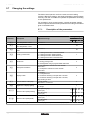
Description of the parameters ...............................56
Modification of the user-level parameters .............58
Modification of the installer-level parameters ........59
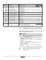
Setting the maximum heat input for central heating
operation ...............................................................59
Return to the factory settings "Reset Param" ........61
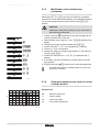
Carrying out an auto-detect ...................................62
Setting the manual mode ......................................62
Switching off the appliance .....................................................................63
6.1
Installation shutdown .........................................63
6.2
Frost protection ..................................................63
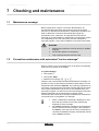
Checking and maintenance .....................................................................64
7.1
Maintenance message ........................................64
7.2
Preventive maintenance with automated "service
message" .............................................................64
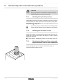
7.2.1
7.2.2
- 123157-AC
Resetting the automatic maintenance
message ................................................................65
Dealing with the next maintenance message and
starting the new maintenance period ....................65
3
Contents
7.3
Standard inspection and maintenance
operations ...........................................................66
7.3.1
7.3.2
7.3.3
7.3.4
7.3.5
7.3.6
7.3.7
7.4
Specific maintenance operations ......................70
7.4.1
7.4.2
7.4.3
8
Checking the hydraulic pressure ...........................66
Checking the ionisation current .............................66
Checking the tightness of the combusted gases
evacuation and air inlet connections .....................66
Checking combustion ............................................67
Checking the automatic air vent ............................67
Checking the siphon ..............................................68
Checking the burner and cleaning the heat
exchanger .............................................................69
Inspection of the ignition electrode ........................70
Replacing the non-return valve .............................71
Assembling the boiler ............................................72
Troubleshooting .......................................................................................73
8.1
Error codes ..........................................................73
8.2
Shutdowns and lock-outs ..................................76
8.2.1
8.2.2
8.3
Error memory ......................................................78
8.3.1
8.3.2
9
Blockage ...............................................................76
Lock-out ................................................................76
Error readout memorised ......................................79
Deletion of the error display ..................................80
Spare parts ................................................................................................81
10
9.1
General ................................................................81
9.2
Spare parts ..........................................................81
Checklists .................................................................................................86
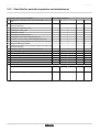
10.1 Checklist for commissioning .............................86
10.2 Checklist for periodic inspection and
maintenance ........................................................87
- 123157-AC
4
- 123157-AC
5
1. Introduction
1
Introduction
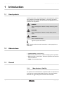
1.1
Used symbols
Quinta Pro 30 - 45 - 65 - 90 - 115
In these instructions, various danger levels are employed to draw the
user's attention to particular information. In so doing, we wish to
safeguard the user's safety, obviate hazards and guarantee correct
operation of the appliance.
DANGER
Risk of a dangerous situation causing serious physical
injury.
WARNING
Risk of a dangerous situation causing slight physical
injury.
CAUTION
Risk of material damage.
Signals important information.
¼ Signals a referral to other instructions or other pages in the
instructions.
1.2
Abbreviations
4 Central heating: Central heating
4 PCU: Primary Control Unit - PCB for managing burner operation
4 SCU: Secondary Control Unit - Electronic printed circuit board for
extra connections
4 PWM: Pulse Wide Modulation
1.3
General
1.3.1.
Manufacturer's liability
Our products are manufactured in compliance with the requirements
of the various european applicable Directives. They are therefore
delivered with [ marking and all relevant documentation.
6
- 123157-AC
Quinta Pro 30 - 45 - 65 - 90 - 115
1. Introduction
In the interest of customers, we are continuously endeavouring to
make improvements in product quality. All the specifications stated in
this document are therefore subject to change without notice.
Our liability as the manufacturer may not be invoked in the following
cases:
4 Failure to abide by the instructions on using the appliance.
4 Faulty or insufficient maintenance of the appliance.
4 Failure to abide by the instructions on installing the appliance.
1.3.2.
Installer's liability
The installer is responsible for the installation and inital start up of the
appliance. The installer must respect the following instructions:
4 Read and follow the instructions given in the manuals provided
with the appliance.
4 Carry out installation in compliance with the prevailing legislation
and standards.
4 Perform the initial start up and carry out any checks necessary.
4 Explain the installation to the user.
4 If a maintenance is necessary, warn the user of the obligation to
check the appliance and maintain it in good working order.
4 Give all the instruction manuals to the user.
1.3.3.
User's liability
To guarantee optimum operation of the appliance, the user must
respect the following instructions:
4 Read and abide by the instructions given in the user manual.
4 Call on qualified professionals to carry out installation and initial
start up.
4 Get your fitter to explain your installation to you.
4 Have the required checks and services done.
4 Keep the instruction manuals in good condition close to the
appliance.
This appliance is not intended to be used by persons (including
children) whose physcial, sensory or mental capacity is impaired or
persons with no experience or knowledge, unless they have the
benefit, through the intermediary of a person responsible for their
safety, of supervision or prior instructions regarding use of the
appliance. Care should be taken to ensure that children do not play
with the appliance.
- 123157-AC
7
1. Introduction
1.4
Quinta Pro 30 - 45 - 65 - 90 - 115
Homologations
1.4.1.
Certifications
CE identification no PIN 0063CL3333
NOx classification 5 (EN 297 pr A3, EN 656)
Type of connection B23, B23P, B33, C13, C33, C43, C53, C63, C83, C93
(Flue gas outlet)
1.4.2.
Equipment categories
Gas category Gas type
Connection pressure (mbar)
II2H3P
20
G20 (Gas H)
G31 (Propane) 37/50
1.4.3.
Additional Directives
Apart from the legal provisions and Directives, the additional
Directives described in these instructions must also be observed.
For all provisions and Directives referred to in these instructions, it is
agreed that all addenda or subsequent provisions will apply at the
time of installation.
1.4.4.
Factory test
Before leaving the factory, each boiler is set for optimum performance
and tested to check the following items:
4 Electrical safety
4 Adjustment (CO2)
4 Water tightness
4 Gas tightness
4 Parameter settings
8
- 123157-AC
Quinta Pro 30 - 45 - 65 - 90 - 115
2. Safety instructions and recommendations
2
Safety instructions and
recommendations
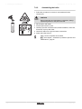
2.1
Safety instructions
DANGER
If you smell gas:
1.
2.
3.
4.
5.
6.
Do not use a naked flame, do not smoke, do not
operate electrical contacts or switches ( doorbell,
light, motor, lift, etc..).
Isolate the gas supply.
Open the windows.
Report any leaks immediately.
Trace possible leaks and seal them immediately.
If the gas leak is before the gas meter, contact the
gas supplier.
DANGER
If you smell flue gases:
1.
2.
3.
4.
2.2
Switch the appliance off.
Open the windows.
Report any leaks immediately.
Trace possible leaks and seal them immediately.
Recommendations
WARNING
4
4
4
Installation and maintenance of the boiler must be
carried out by a qualified professional in compliance
with prevailing local and national regulations.
When working on the boiler, always disconnect the
boiler from the mains and close the main gas inlet
valve.
After maintenance or repair work, check all
installations to ensure that there are no leaks.
CAUTION
The boiler must be installed in a frost-free environment.
Keep this document close to the place where the boiler is
installed.
- 123157-AC
9
2. Safety instructions and recommendations
Quinta Pro 30 - 45 - 65 - 90 - 115
Casing components
Only remove the casing for maintenance and repair operations. Put
the casing back in place after maintenance and repair operations.
Instructions stickers
The instructions and warnings affixed to the appliance must never be
removed or covered and must remain legible during the entire lifespan
of the boiler. Immediately replace damaged or illegible instructions
and warning stickers.
Modifications
Modifications may only be made to the boiler after the written
permission of Remeha B.V. to do so.
10
- 123157-AC
Quinta Pro 30 - 45 - 65 - 90 - 115
3. Technical description
3
Technical description
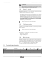
3.1
General description
High-efficiency wall-hung condensing gas boilers
4 High efficiency heating (Production of domestic hot water can be
ensured by a separate hot water calorifier).
4 Low pollutant emissions.
4 Very suitable for cascade systems with several boilers.
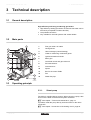
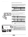
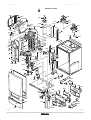
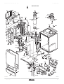
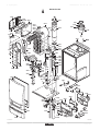
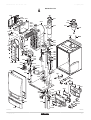
3.2
Main parts
1
Flue gas outlet / Air intake
2
2
Casing/air box
3
3
Heat exchanger (Central heating)
4
Outlet for measuring combustion gases
5
Ignition/ionization electrode
6
Mixer pipe
7
Combined venturi and gas valve unit
8
Áir intake silencer
9
Instrument box
10
Siphon
11
Box for the control PCBs
12
Fan
13
Water flow pipe
1
13
4
5
12
6
7
8
11
10
9
T002036-B
3.3
Operating principle
3.3.1.
Shunt pump
The boiler is supplied without a pump. When choosing a pump, take
account of the boiler resistance and system resistance.
¼ See chapter: "Technical characteristics", page 12.
If possible, install the pump directly under the boiler on the return
connection.
¼ See chapter: "Connection of the heating circuit", page 20.
- 123157-AC
11
3. Technical description
Quinta Pro 30 - 45 - 65 - 90 - 115
CAUTION
The pump may have a maximum input of 200 W. Use an
auxiliary relay for a pump with a larger input.
3.3.2.
System in cascade
The boiler is ideally suited for a cascade system. There are a number
of standard solutions available. For example:
4 Cascade sets (quick assembly) for the installation of 2 to 6 boilers
next to each other or 3 to 6 boilers mounted back to back on a freestanding frame. When the boilers are mounted next to each other,
they can be mounted either on the wall or on a free-standing frame.
4 Low loss headers for a cascade system of 2 or 3 boilers (Quinta
Pro 45 and/or Quinta Pro 65). The flow and return of each boiler
can be directly connected to these.
Please contact us for further information.
3.3.3.
Calorifier connection
A calorifier can be connected to the boiler. Our product range includes
various calorifiers.
Please contact us for further information.
The calorifier can be connected to the boiler in two ways:
4 Using a three-way valve.
4 Using a calorifier pump.
3.3.4.
Water flow rate
The boiler's modulating control system limits the maximum difference
in temperature between the heating flow and return and the maximum
speed at which the flow temperature increases. For this reason the
boiler is, so to speak, insensitive to a flow which is too low.
In all cases, maintain a minimum water flow of 0.4 m3/h.
3.4
Technical characteristics
Boiler type
Quinta Pro
30
45
65
90
115
General
EC indentification no.
PIN
Flow rate setting
Adjustable
0063CL3333
Modulating, Start/Stop, 0 - 10 V
(1) Front panel removed
12
- 123157-AC
Quinta Pro 30 - 45 - 65 - 90 - 115
Boiler type
3. Technical description
Quinta Pro
30
45
65
90
115
minimummaximum
kW
Factory setting
kW
minimummaximum
kW
Factory setting
kW
minimummaximum
kW
Factory setting
kW
minimummaximum
kW
Factory setting
kW
33.3
45.7
68.8
95.5
122.4
Heating efficiency under full load
(Hi) (80/60 °C)
-
%
97.5
97.2
98.3
97.9
96.6
Heating efficiency under full load
(Hi) (50/30 °C)
-
%
102.9
102.9
104.6
104.1
102.5
Heating efficiency under partial
load (Hi) (Return temperature
60°C)
-
%
97.5
97.5
98.3
96.6
96.5
%
107.7
107.7
108.9
108.1
107.1
<32
< 39
<39
Nominal output (Pn)
Heating System (80/60 °C)
Nominal output (Pn)
Heating System (50/30 °C)
Nominal input (Qn)
Heating System (Hi)
Nominal input(Qn)
Heating System (Hs)
Heating efficiency under partial
load (EN 92/42)(Return
temperature 30°C)
Data on the gases and combustion gases
NOx-Emission per year or (EN 483)
Gas inlet pressure G20 (Gas H)
8.0 - 29.3 8.0 - 40.0 12.0 - 61.0 14.1 - 84.2 16.6 - 107.0
29.3
40.0
61.0
84.2
107.0
8.9 - 31.4 8.9 - 43.0 13.3 - 65.0 15.8 - 89.5 18.4 - 114.0
31.4
43.0
65.0
89.5
114.0
8.2 - 30.0 8.2 - 41.2 12.2 - 62.0 14.6 - 86.0 17.2 - 110.2
30.0
41.2
62.0
86.0
110,2
9.1 - 33.3 9.1 - 45.7 13.6 - 68.8 16.2 - 95.5 19.1 - 122.4
Equipment categories: II2H3
mg/kWh
<35
<37
minimummaximum
mbar
17- 30
Gas inlet pressure G31 (Propane) minimummaximum
mbar
37 - 50
Gas consumption G20 (Gas H)
minimummaximum
m3/h
0.9 - 3.3
0.9 - 4.4
1.3 - 6.6
1.5 - 9.1
1.8 - 11.7
Gas consumption G31 (Propane)
minimummaximum
m3/h
0.3 - 1.3
0.3 - 1.7
0.5 - 2.5
0.6 - 3.5
0.6 - 4.7
Mass flue gas flow rate
minimummaximum
kg/h
14 - 50
14 - 69
21 - 104
28 - 138
36 - 178
Flue gas temperature
minimummaximum
°C
30- 65
30 - 67
30 - 68
30 - 68
30 - 72
Maximum counter pressure
Characteristics of the heating circuit
Pa
70
150
100
160
220
Water content
l
5.5
5.5
6.5
7.5
7.5
0.3
0.5
140
250
Water operating pressure
minimum
bar
0,8
Water operating pressure (Open
vented)
minimum
bar
Water operating pressure (PMS)
maximum
bar
4.0
Water temperature
0.3
0.3
0.3
maximum
°C
110
Water temperature (Open vented) maximum
°C
95
Operating temperature
maximum
°C
90
Operating temperature (Open
vented)
maximum
°C
80
Water resistance (∆T = 20K)
Electrical characteristics
mbar
Power supply voltage
70
90
VAC/Hz
130
230/50
Power consumption - Full load
maximum
W
39
68
88
125
199
Power consumption - Part load
maximum
W
18
18
23
20
45
Power consumption - Standby
maximum
W
5
5
6
4
7
(1) Front panel removed
- 123157-AC
13
3. Technical description
Boiler type
Quinta Pro 30 - 45 - 65 - 90 - 115
Quinta Pro
Electrical protection index
Other characteristics
Weight (empty)
Acoustic level at 1 meter
30
45
65
IP
90
115
X4D
Total
kg
53
53
60
67
68
Mounting(1)
kg
49
49
56
65
65
dB(A)
38
45
45
52
51
(1) Front panel removed
14
- 123157-AC
Quinta Pro 30 - 45 - 65 - 90 - 115
4. Installation
4
Installation
4.1
Regulations governing installation
WARNING
Installation of the appliance must be done by a qualified
engineer in accordance with prevailing local and national
regulations. The engineer must be Gas Safe registered
and have the correct ACS qualifications.
4.2
Package list
4.2.1.
Standard delivery
The delivery includes:
4 The boiler, fitted with a connection cable
4 Connection cable for pump
4 Mounting rail and mounting accessories for wall mounting
4 Mounting template
4 Installation and Service Manual
These installation and maintenance instructions deal only with the
items included in a standard delivery. For installation and assembly
of any accessories supplied with the boiler, see the relevant
installation/assembly instructions.
4.2.2.
Accessories
Description
Remeha Celcia 10 on/off thermostat
Remeha Celcia 15 basic modulating control system
Remeha iSense extended modulating control system
Cascade controller
Outside temperature sensor
Flue kit
Combustion gas adapter 80/80 (Quinta Pro 30/45)
Combustion gas adapter 100/100 (Quinta Pro 65/90/115)
Calorifier tank
Kit for connection to the water heater
DHW sensor
Modulating pump
3 -speed pump
- 123157-AC
15
4. Installation
Quinta Pro 30 - 45 - 65 - 90 - 115
Description
Flue gas thermostat
Cascade set (For fitting a Quinta Pro boiler in a Quinta cascade frame)
Cascade set
Duo and Trio low loss headers
Various control PCBs
Protective cover for the connections
Exchanger cleaning tool
Maintenance box
Recom communication kit
4.3
Choice of the location
4.3.1.
Data plate
The data plate located on top of the boiler provides important
information on the appliance: serial number, model, gas category, etc.
T001982-A
16
- 123157-AC
Quinta Pro 30 - 45 - 65 - 90 - 115
4. Installation
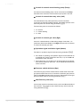
4.3.2.
50
0
mi
n
40 .
0
Location of the appliance
4 Before mounting the boiler, decide on the ideal position for
mounting, bearing the Directives and the dimensions of the
appliance in mind.
4 When choosing the position for mounting the boiler, bear in mind
the authorised position of the combustion gas discharge outlets
and the air intake opening.
4 To ensure adequate accessibility to the appliance and facilitate
maintenance, leave enough space around the boiler.
WARNING
75
0
4
35
0
4
mi
n
25 .
0
50
Fix the appliance to a solid wall capable of bearing
the weight of the appliance when full of water and fully
equipped.
It is forbidden to store inflammable products and
materials in the boiler room or close to the boiler,
even temporarily.
CAUTION
0
4
0
00
n.1
mi
4
T002599-B
4
4.3.3.
The boiler must be installed in a frost-free
environment.
An earthed electrical connection must be available
close to the boiler.
A connection to the mains drainage system for the
discharge of condensate must be available close to
the boiler.
Ventilation
If the boiler is installed in a compartment, the installation and
ventilation must comply with BS 5540 (part 1 + 2), BS 6640 and IGUP/
10.
- 123157-AC
17
4. Installation
Quinta Pro 30 - 45 - 65 - 90 - 115
4.3.4.
Main dimensions
191
500
100
750
500
50
130
191
365
50
T002614-C
18
i
Connection of the combustion gas exhaust pipe ; Ø 80
mm (≤ 45 kW)
Connection of the combustion gas exhaust pipe ; Ø 100
mm (≥ 65 kW)
h
Connection of the air intake pipe ; Ø 125 mm (≤ 45 kW)
Connection of the air intake pipe ; Ø 150 mm (≥ 65 kW)
â
Siphon connection bush
z
Gas /
Gaz
Heating circuit return ; 1 ¼" Male thread
{
Heating circuit flow ; 1 ¼" Male thread
Gas connection ; ¾" Male thread
- 123157-AC
Quinta Pro 30 - 45 - 65 - 90 - 115
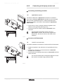
4.4
4. Installation
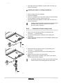
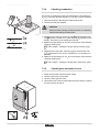
Positioning the boiler
The boiler is delivered with a mounting template.
A suspension clamp situated at the rear of the casing enables the
boiler to be directly suspended on the mounting bracket.
1
1. Position the mounting template to the wall with adhesive tape.
2
CAUTION
3
4
4
4
Using a spirit level, check that the mounting axis is
perfectly horizontal.
During mounting, cover up the connection points for
the air supply and the combustion gas exhaust, to
protect the boiler and its connections from dust. Only
remove this protection at the time when these
connections are made.
2. Drill 2 holes with a Ø of 10 mm.
3. Insert the Ø 10 mm rawplugs.
4. Attach the mounting bracket to the wall with the Ø 10 mm bolts
provided.
5. Hang the boiler on the mounting bracket.
5
T001540-A
4.5
Hydraulic connections
4.5.1.
Flushing the system
The installation must be cleaned and flushed according to BS 7593
(2006).
n Installing the boiler in new installations (installations
less than 6 months old)
4 Clean the installation with a universal cleaner to eliminate debris
from the appliance (copper, flaxen thread, flux).
- 123157-AC
19
4. Installation
Quinta Pro 30 - 45 - 65 - 90 - 115
4 Thoroughly flush the installation until the water runs clear and
shows no impurities.
n Installing the boiler in existing installations
4 Remove sludge from the installation.
4 Flush the installation.
4 Clean the installation with a universal cleaner to eliminate debris
from the appliance (copper, flaxen thread, flux).
4 Thoroughly flush the installation until the water runs clear and
shows no impurities.
Suitable chemicals and their use should be discussed with
specialist water treatment companies in respect to
aluminium heat exchangers.
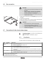
4.5.2.
Connection of the heating circuit
1. Remove the anti-dust plug located on the heating outlet
connection { under the boiler.
2. Connect the heating water outlet pipe to the heating flow
connection.
3. Install a filling and drainage valve on the installation for filling and
draining the boiler.
T002856-C
4. Remove the anti-dust button located on the heating return
connection z under the boiler.
5. Connect the heating water return pipe to the heating return
connection.
6. Fit the pump in the return pipe (if possible).
¼ For the electrical connection of the pump, see chapter:
"Connecting the pump", page 29
To facilitate maintenance work, we recommend mounting
a shut off valve on the heating flow and return pipes.
T002857-B
20
- 123157-AC
Quinta Pro 30 - 45 - 65 - 90 - 115
4. Installation
CAUTION
4
4
4
4.5.3.
The heating pipe must be mounted in accordance
with prevailing provisions.
If installing shut off valves, position the filling/
drainage valve, the expansion vessel and the safety
valve between the shut off valves and the boiler.
When installing open vented systems, the cold feed
and expansion tank heights must comply with the
requirements laid down in the Health and Safety
Executive publication PM5. The Quinta Pro boilers
require a minimum static head of 3 (Quinta Pro
30/45/65/90) or 5 (Quinta Pro 115) m.
Connecting the expansion vessel
Install the expansion vessel on the heating return pipe z.
4.5.4.
Connecting the condensate discharge pipe
1. Fit the condensate drain hose and the syphon of the boiler: these
are supplied separately.
2. Mount a standard drainage pipe, Ø 32 mm or more, leading to the
mains drainage system.
3. Insert into this the hose of the condensate drain â.
4. Mount a trap or a siphon in the discharge pipe.
CAUTION
Do not make a fixed connection owing to maintenance
work on the siphon.
T002858-B
4
Do not plug the condensate discharge pipe.
4
Set the discharge pipe at a gradient of at least 30
mm per metre, maximum horizontal length 5 metres.
Do not drain condensation water into a roof gutter at
any time.
Connect the condensate discharge pipe in
accordance with prevailing standards.
4
4
- 123157-AC
21
4. Installation
4.6
Quinta Pro 30 - 45 - 65 - 90 - 115
Gas connection
WARNING
4
4
4
Close the main gas valve before starting work on the
gas pipes.
Before mounting, check that the gas meter has
sufficient capacity. To do this, you should keep in
mind the consumption of all appliances.
If the gas meter has too low a capacity, inform the
energy supply company.
1. Remove the anti-dust plug from the GAS/GAZ gas inlet pipe under
the boiler.
2. Connect the gas inlet pipe.
3. Mount a gas isolation valve on this pipe, directly under the boiler.
4. Connect the gas pipe to the gas shut off valve.
CAUTION
4
Ensure that there is no dust in the gas pipe.
4
We recommend installing a gas filter on the gas pipe
to prevent clogging of the gas valve unit.
Connect the gas pipe in accordance with prevailing
standards and regulations.
T002859-C
4
4.7
Connections for the air and exhaust pipes
The boiler is suitable for connection to the following types
of combustible gases.
¼ See chapter: "Certifications", page 8.
4.7.1.
Classification
The table specifies this classification in detail according to [.
Type
Execution
B23
open
Description
4
Without fire-stop approval.
B23P(1)
4
Exhaust of combustion gases above the roof.
B33
4
4
Air in the installation room.
Without fire-stop approval.
4
Common exhaust of combustion gases above the roof.
4
Common exhaust of combustion gases mixed in the air, air in the installation room (special
construction).
Vent in the outside wall.
C13
open
closed
4
4
(1)
(2)
(3)
(4)
22
The opening for the air-supply inlet is located in the same pressure zone as the vent (For example,
a common passage through the outside wall).
Including the pressure classification P1
EN483: 0,5 mbar suction by pressure reduction
An under pressure of 4 mbar is possible
See table for minimum sizes of duct or sleeving
- 123157-AC
Quinta Pro 30 - 45 - 65 - 90 - 115
Type
Execution
C33
closed
Description
4
Exhaust of combustion gases above the roof.
4
4
4
The opening for the air-supply inlet is located in the same pressure zone as the vent (For example,
a concentric passage to the roof).
Common channelling for the air-supply and exhaust of combustion gases (CLV):
Concentric.
Eccentric ; Air supply from the shaft.
This also relates to the overpressure cascades.
Closed equipment.
4
Separate channelling for the air-supply.
4
Separate channelling for the combustion gases.
Terminating on different pressure surfaces.
The manufacturer delivers this type of equipment without a supply or exhaust system.
The equipment can be connected on a so-called semi-CLV system (with common combustion
gas exhaust).
Channel for the air-supply and exhaust fumes in a duct or surrounded by a sleeve:
Concentric.
Eccentric ; Air supply from the shaft.
Exhaust of combustion gases above the roof.
The opening for the air-supply inlet is located in the same pressure zone as the vent.
C43(2)
closed/Cascade 4
C53
closed
C63
closed
4
4
C83(3)
closed
4
C93(4)
closed
4
(1)
(2)
(3)
(4)
4. Installation
Including the pressure classification P1
EN483: 0,5 mbar suction by pressure reduction
An under pressure of 4 mbar is possible
See table for minimum sizes of duct or sleeving
Type Execution
C93
Minimum size of the duct or jacket.
Diameter
Rigid
Flexible
Concentric
∅ Channel
∅ Channel
⃞ Channel
⃞ Channel
(Without air-supply) (With air-supply) (Without air-supply) (With air-supply)
60 mm
110 mm
120 mm
110 x 110 mm
110 x 110 mm
80 mm
130 mm
140 mm
130 x 130 mm
130 x 130 mm
100 mm
160 mm
170 mm
160 x 160 mm
160 x 160 mm
60 mm
110 mm
120 mm
110 x 110 mm
110 x 110 mm
80 mm
130 mm
145 mm
130 x 130 mm
130 x 130 mm
100 mm
160 mm
170 mm
160 x 160 mm
160 x 160 mm
60/100 mm
120 mm
120 mm
120 x 120 mm
120 x 120 mm
80/125 mm
145 mm
145 mm
145 x 145 mm
145 x 145 mm
100/150 mm
170 mm
170 mm
170 x 170 mm
170 x 170 mm
4.7.2.
Outlets
For exhausting combustion gases of types C1, C3 and C5, it is
appropriate to use a M&G Skyline / Mugro 3000 or a Coxstand E
HR. When exhausting combustion gases of type C6, the material of
the exhaust must conform with Gastec QA and/or be provided with
CE marking.
The exhaust vent for combustion gases must conform to EN
1856-1. The construction of the equipment for exhausting the
combustion gases must be calculated conforming to EN 13384 (parts
1 & 2).
For open exhaust of combustion gases above the roof, the
vent must always be provided with a suitable RVS wire grill.
- 123157-AC
23
4. Installation
Quinta Pro 30 - 45 - 65 - 90 - 115
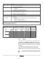
4.7.3.
Lengths of the air/flue gas pipes
The boiler is also suitable for longer chimney lengths with
diameters other than those indicated in the table. Please
contact us for further information.
n Open flue (B23, B23P, B33)
If using an open version, the air supply opening remains open; only
the combustion gas opening is connected. The boiler then takes in
the combustion air required directly from the premises in which it is
installed.
CAUTION
4
The air supply opening must remain open.
4
The premises in which the appliance is installed must
be fitted with the necessary air supply openings.
They must not be reduced or closed.
Maximum length (L)
T002998-A
Diameter
Quinta Pro
30
45
65
80 mm 40 m 33 m 10 m
90
115
9m
8m
90 mm 40 m 40 m 18 m 16 m 12 m
100 mm 40 m 40 m 27 m 24 m 19 m
110 mm 40 m 40 m 40 m 40 m 37 m
n Room sealed flue (C13, C33, C43, C63, C93)
If using a room sealed version, both the combustion gas exhaust
opening and the air supply opening must be connected
(concentrically). Refer to the table to determine the maximum pipe
length of the flue gas pipes in room sealed operation.
To define the maximum final length, you must remove the
pipe length in accordance with the reduction table.
L
Chimney length for room sealed operation
Maximum length (L)
Diameter
Quinta Pro
30
45
80-125 mm 20 m 16 m
65
90
115
-
-
-
100-150 mm 20 m 20 m 13 m 13 m 7 m
T001882-B
24
- 123157-AC
Quinta Pro 30 - 45 - 65 - 90 - 115
4. Installation
n Connection in areas of different pressure (C53, C83)
Combustion air supply and combustion gas discharge are possible in
various pressure zones, semi-CLV systems. With the exception of
coastal areas. The maximum permissible difference in height
between the combustion air supply and the combustion gas discharge
is 36 m.
L
To define the maximum final length, you must remove the
pipe length in accordance with the reduction table.
Chimney length in the various pressure zones
Maximum length (L)
Diameter
Quinta Pro
30
45
65
90
115
80 mm
20 m
20 m
-
-
-
T000780-C
90 mm
36 m
36 m
2m
-
-
100 mm
36 m
36 m
8m
4m
-
110 mm
36 m
36 m
34 m
22 m
24 m
130 mm
36 m
36 m
36 m
36 m
36 m
n Reduction table
Pipe reductions per element used
Elbow 45°
Diameter
Elbow 90°
Pipe reduction Pipe reduction
80 -125 mm
1m
2m
100 -150 mm
1m
2m
Pipe reductions per element used
Diameter
Elbow 45°
Elbow 90°
Pipe reduction Pipe reduction
80 mm
1,2 m
4,0 m
90 mm
1,3 m
4,5 m
100 mm
1,4 m
4,9 m
110 mm
1,5 m
5,4 m
130 mm
1,0 m
6,2 m
4.7.4.
Additional Directives
4 Connection of the combustion gas exhaust directly to the buildings
brick chimneys or flues is forbidden for condensation reasons.
4 If flues or chimneys are to be used, they must have an airtight
construction with thick walls and be made from rigid aluminium or
stainless steel. Flexible supply flue pipes made from plastic or
stainless steel are also permissible. Aluminium is permissible only
if there is no contact between the building supply section and the
combustion gas exhaust pipe.
- 123157-AC
25
4. Installation
Quinta Pro 30 - 45 - 65 - 90 - 115
4 Always clean the ducts thoroughly in cases where lining pipes are
used and/or a connection of the air-supply.
4 It must be possible to inspect the flue or chimney.
4 For long, aluminium, combustion-gas exhaust pipes it is initially
necessary to consider the relatively high quantity of corrosive
products which are brought together with the condensate from the
exhaust pipe. The siphon on the equipment requires regular
cleaning or, preferably, an additional condensate collector can be
installed above the equipment.
4 If the regular formation of surplus condensates is to be expected
in the combusted gas discharge pipe (e.g. when the boiler is
running on high and, consequently, the combusted gases can only
be condensated in the boiler up to a point), we recommend
constructing the combusted gas discharge pipe in stainless steel
or synthetic materials. If aluminium is chosen, a high quality
(approved brand) of aluminium must be used. The combusted gas
discharge pipe must be sufficiently inclined towards the boiler (at
least 50 mm per metre) and an adequate condensate collection
tank and discharge system constructed (at least 1 m before the
boiler opening). The condensates strainer must be inspected and,
if necessary, cleanable. The elbows fitted must be at more than
90° to guarantee the provision of an adequate gradient and
tightness on the lip rings.
Please contact us for further information.
Connection of the combustion gas exhaust
pipe
4.7.5.
S
S
Insertion depth 25 mm
Mounting
80/125 mm
100/150 mm
Fit together the combustion gas exhaust pipes, without welding.
4
4
4
The pipes must allow no leakage of flue gases and be
resistant to corrosion.
Connect the pipes together without stress between
the sections.
The horizontal sections will be constructed with a
gradient of 50 mm per metre: Boiler orientation.
T001990-A
4.8
Electrical connections
4.8.1.
Control unit
The boiler is not live- and neutral-sensitive. The boiler is fully prewired. All external connections can be made on the connection
connector (low voltage). The main characteristics of the control unit
are described in the table below.
26
- 123157-AC
Quinta Pro 30 - 45 - 65 - 90 - 115
4. Installation
Power supply voltage
230 VAC/50Hz
Rating of the main fuse F1 (230 VAC) 6.3 AT
Fuse rating F2 (230 VAC)
2 AT
Fan
230 VAC
CAUTION
The following components of the appliance are at a
voltage of 230 V:
4 Electrical connection of the heating pump (Central
heating).
4 Electrical connection of the combined gas valve unit.
4
Electrical connection of the fan.
4
The majority of components in the control panel.
4
Ignition transformer.
4
Connection of the power supply cable.
CAUTION
4
When the power supply cable has to be replaced, it
must be ordered from Remeha.
It is possible to connect various control, safety and regulation systems
to the boiler. The standard control PCB can be extended with:
¼ For the optional PCBs, see chapter: "Optional electrical
connections", page 35
4.8.2.
Recommendations
WARNING
4
4
4
Only qualified professionnals may carry out electrical
connections, always with the power off.
The boiler is entirely pre-wired. Do not modify the
connections inside the control panel.
Earth the appliance before making any electrical
connections.
Make the electrical connections of the appliance according to:
4 the instructions of the prevailing standards.
4 the instructions on the circuit diagrams provided with the
appliance.
4 the recommendations in the instructions.
CAUTION
Separate the sensor cables from the 230 V cables.
- 123157-AC
27
4. Installation
Quinta Pro 30 - 45 - 65 - 90 - 115
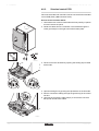
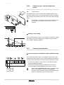
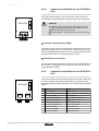
4.8.3.
Standard control PCB
Various thermostats and controllers can be connected to the standard
control PCB (PCU) (X12 connector block).
Access to the connector block:
1. Unscrew the two screws located under the front panel by a quarter
turn and remove the panel.
2. Guide the cables from the controller or thermostat through the
round grommet(s) on the right in the boiler bottom plate.
2
90º
1
T001514-A
3. Tilt the control box forwards by opening the holding clips located
at the sides.
2
1
1
T001991-A
4. Open the tooling box by opening the clip fastener on the front side.
5. Run the connection cable(s) through the grommet(s) in the control
unit box.
6. Unscrew the necessary cable clamps (to access the connector
block) and introduce the cables.
1
2
T001577-A
28
- 123157-AC
Quinta Pro 30 - 45 - 65 - 90 - 115
4. Installation
7. Connect the cable to the appropriate terminals on the connector
block.
8. Firmly retighten the cable clamps and close the control box.
t
Tou
w
Tdh
RL
ff
On/o
BL
OT
X12
X13
T001578-B
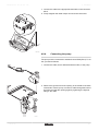
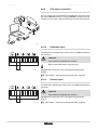
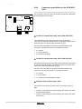
4.8.4.
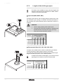
Connecting the pump
The pump must be connected to standard control PCB (PCU). To do
this, proceed as follows:
1. Connect the cable, that is delivered with the boiler, to the pump.
X81
X81
T002047-B
2. Remove the grommet from the opening in the middle of the base
of the boiler. Pass the pump connection cable through the base of
the boiler and seal the opening again by tightening the bayonet
fitting to the cable.
1
2
3
T002048-A
- 123157-AC
29
4. Installation
Quinta Pro 30 - 45 - 65 - 90 - 115
3. Connect the pump connection cable to the cable in the instrument
box that is connected with connector X8.
X8
X81
X81
T002050-C
4. Connect the pump connection cable to the cable bundle by
opening and closing the cable bundle bands.
T002049-B
30
- 123157-AC
Quinta Pro 30 - 45 - 65 - 90 - 115
4. Installation
4.8.5.
Connecting a third party control unit
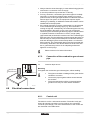
n Connecting modulating controller
OT
OT
OpenTherm regulator
The boiler is fitted with a OpenTherm connection as standard.
As a result, modulating OpenTherm controllers can be connected
without further modifications (Room, weather-dependent and
cascade controllers). The boiler is also suitable for OpenTherm
Smart Power.
4 In the case of a room controller: Install the regulator in the
reference room (generally the living room).
4 Connect the two-wire cable to terminals On/off-OT of the
connector.
Tdhw
Tout
RL
ff
On/o
BL
OT
If the tap water temperature can be set on the
OpenTherm controller, then the boiler supplies this
temperature, with the set value on the boiler as the
maximum.
On/off
OT
RL
BL
Tout Tdhw
T000776-D
n Connect on/off thermostat
Tk
The boiler is suitable for connection to a 2 wire on/off room thermostat.
Tk
4 Install the regulator in the reference room (generally the living
room).
4 Connect the 2 wire 24V room thermostat to the On/off-OT
terminals of the connector.
4 Connect the power stealing thermostat to the On/off-OT terminals
of the connector.
Tdhw
Tout
RL
ff
On/o
BL
OT
If a room thermostat with an anticipation element is used,
this must be converted using parameter p5.
On/off
OT
ON/OFF room thermostat
BL
RL
Tout Tdhw
T001590-B
- 123157-AC
31
4. Installation
Quinta Pro 30 - 45 - 65 - 90 - 115
4.8.6.
Ba
Ba
Connecting the outside temperature
sensor
Outside sensor
An outside sensor can be connected to the Tout terminals of the
connector. Where there is an on/off thermostat controller, the boiler
will control the temperature with the set point of the internal heating
curve.
A OpenTherm controller can also use this outside sensor.
The heating curve required must then be set on the
controller.
Tdhw
Tout
RL
ff
On/o
BL
OT
On/off
OT
BL
RL
Tout Tdhw
T001591-B
n Heating curve setting
If an outside temperature sensor is connected, it is possible to adapt
the heating curve. The setting can be modified using parameters
p1, p"5, p"6 and p"7.
80
60
F
40
20
-15
0
10
20
T000441-B
4.8.7.
Connect frost protection
n Frost protection in combination with on/off thermostat
On/off
OT
BL
RL
Tout
Tdhw
If an on/off thermostat is used, it is advisable to protect any rooms
where there is risk of frost by using a frost thermostat. The radiator
valve in a room where there is a risk of frost must, however, be open.
4 In rooms where there is a risk of frost, a frost thermostat (Tv)
should preferably be installed.
4 Connect the frost thermostat in parallel with an on/off room
thermostat (Tk) to the On/off-OT terminals of the connector.
Tk
Tv
T000778-C
32
When using a OpenTherm thermostat, a frost thermostat
cannot be connected in parallel to the On/off-OT
terminals. Implement frost protection for the central heating
system in combination with an external sensor.
- 123157-AC
Quinta Pro 30 - 45 - 65 - 90 - 115
4. Installation
n Frost protection in combination with an outside sensor
The central heating system can also be protected against frost in
combination with an outside sensor. The radiator valve in a room
where there is a risk of frost must, however, be open. Connect the
outside sensor to the Tout terminals of the connector.
The frost protection functions as follows where an outside sensor is
used:
4 At an outside temperature lower than -10°C (can be set with
parameter p30): the circulation pump switches on.
4 At an outside temperature higher than -10°C (can be set with
parameter p30): the circulation pump continues to run and then
switches off.
4.8.8.
Ws
Ws
Connecting the calorifier sensor/
thermostat
DHW sensor
Connect the calorifier sensor or thermostat to the Tdhw terminals of
the connector.
Tdhw
Tout
RL
ff
On/o
BL
OT
On/off
OT
BL
RL
Tout Tdhw
T000443-B
- 123157-AC
33
4. Installation
Quinta Pro 30 - 45 - 65 - 90 - 115
4.8.9.
PC/Laptop connection
A PC or Laptop can be connected to the telephone connector using
the optional Recom interface. Using the Recom PC/Laptop service
software, you can enter, change and read out various boiler settings.
Tou
RL
ff
On/o
BL
OT
X13
T000442-A
4.8.10.
On/off
OT
BL
RL
Tout
Tdhw
Shutdown input
The boiler has a shutdown input. This input is on the BL terminals of
the connector.
CAUTION
Only suitable for potential-free contacts.
Remove the bridge before using the input
T001917-B
The behaviour of the input can be changed using parameter
p36.
¼ See chapter: "Description of the parameters", page 56
4.8.11.
On/off
OT
BL
RL
Tout
Tdhw
Release input
The boiler has a release input. This input is on the RL terminals of the
connector.
CAUTION
Only suitable for potential-free contacts.
The behaviour of the input can be changed using parameter
p37.
T001917-B
34
¼ See chapter: "Description of the parameters", page 56
- 123157-AC
Quinta Pro 30 - 45 - 65 - 90 - 115
4.9
4. Installation
Optional electrical connections
4.9.1.
Box for the control PCBs
The control PCBs are positioned in the housing for PCBs. See the
instructions provided with the control PCB.
1. Unclip the PCB cover.
2. Remove the cover.
1
Control PCBs IF-01, SCU-S02 and SCU-X01 are already
installed in the housing for PCBs.
x3
2
T002862-A
- 123157-AC
35
4. Installation
Quinta Pro 30 - 45 - 65 - 90 - 115
X4
Connection options for the 0-10 V control
PCB (IF-01)
The IF-01 control PCB can be built into the instrument box or the
housing for the control PCBs. Refer to the instructions supplied with
the product.
0 +
0 +
OTm
X1
Status
IF-01
OTm 0 + 0 +
X5
Nc C No
%
2
Nc C No
1
0-10 0-10
4.9.2.
CAUTION
Do not connect a frost thermostat or room thermostat to
the boiler if using the 0-10 V control PCB.
T000784-A
n Connection status (Nc)
If the boiler locks out, a relay is de-energised and the alarm can be
transmitted via a potential-free contact (maximum 230 V, 1A) on
terminals Nc and C of the connector.
n Connection (OTm)
The interface communicates with the boiler control via OpenTherm.
The OTm connection must be connected to the OpenTherm input
OT of the boiler control.
n Analogue input (0-10 V)
This control can be based on temperature or heat output. The two
controls are described briefly below. For analogue control, the 0-10
V signal must be connected to the interface.
n Analogue temperature-based control (*)
2
2
The 0-10 V signal controls the boiler flow temperature between 0°C
and 100°C. This control modulates on the basis of flow temperature,
whereby the heat output varies between the minimum and maximum
values on the basis of the flow temperature set point calculated by
the controller.
A jumper (2) on the interface is used to select either temperature
1
2%
control (*) or heat output control (%).
Jumper 2 Input signal (V) Temperature À Description
*
T000785-A
36
0 - 1,5
0 - 15
Boiler off
1,5 - 1,8
15 - 18
Hysteresis
1,8 - 10
18 - 100
Temperature required
- 123157-AC
Quinta Pro 30 - 45 - 65 - 90 - 115
4. Installation
n Analogue heat output-based control (%)
The 0-10V signal controls the boiler output between 0% and 100%.
The minimum and maximum values are limited. The minimum output
is linked to the boiler's modulation depth. The output varies between
the minimum and maximum value on the basis of the value
determined by the controller.
Jumper 2 Input signal (V) Heat output (%) Description
%
0 - 2,0(1)
0 - 20
Boiler off
2,0 - 2,2(1)
20 - 22
Hysteresis
2,0 - 10(1)
20 - 100
Heat output requested
(1) Dependent on the minimum modulation depth (set speeds, standard 20%)
n Analogue output (0-10 V)
1
The temperature or heat output can be chosen for this feedback
message. The two controls are described briefly below.
1
A jumper (1) on the interface is used to select either temperature
control (*) or heat output control (%).
Jumper 1 Output signal (V) Temperature À Description
1
2%
*
0,5
-
Alarm
1 - 10
10 - 100
Delivered temperature
Jumper 1 Output signal (V) Heat output (%) Description
0
T000800-A
%
0 - 15
Boiler off
0,5
15 - 20
Alarm
2,0 - 10(1)
20 - 100
Heat output supplied
(1) Dependent on the minimum modulation depth (set speeds, standard 20%)
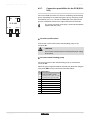
4.9.3.
Connection possibilities for the PCB (SCUS02)
If the boiler is fitted with the control PCB (SCU-S02), then this is
automatically recognised by the automatic control unit of the boiler.
F 4AT
X2
SCU-SO2
On removing this PCB, the boiler will show fault code
e[38. To prevent this fault, an auto-detect must be
carried out after removing this PCB.
¼ See chapter: "Carrying out an auto-detect", page
62.
X1
X3
X4
Pump
3wV
EgV
N L
NCD
N L
Pump
3wV
EgV
N L
NCD
N L
X5
Status
Nc C No
Nc C No
Tsol
Tsol
CAUTION
Gps
Gps
Hru
Hru
T001255-A
- 123157-AC
37
4. Installation
Quinta Pro 30 - 45 - 65 - 90 - 115
n Control of external central heating pump (Pump)
An external central heating pump can be connected to the Pump
terminals of the connector. The maximum input power is 400 VA.
n Control of external three-way valve (3wV)
The external three-way valve (230 VAC) can be used when
connecting an indirectly heated calorifier. The neutral position of the
three-way valve can be set using parameter p34.
The three-way valve is connected as follows:
4 N = neutral
4 C = central heating
4 D = tank
n Control of external gas valve (EgV)
If there is a heat demand, an alternating voltage of 230 VAC, 1 A
(maximum) becomes available on the EgV terminals of the connector
to control an external gas valve.
n Operation signal and failure signal (Status)
The alarm or operation signal is selected using parameter p40.
4 If the boiler is operating, the operation signal can be switched via
a potential-free contact (maximum 230 VAC, 1 A) on the No and
C terminals of the connector.
4 If the boiler locks out, the alarm can be transmitted via a potentialfree contact (maximum 230 VAC, 1 A) on the Nc and C terminals
of the connector.
n Pressure switch minimum (Gps)
The minimum gas pressure switch shuts the boiler down if the inlet
gas pressure becomes too low. Connect the minimum gas pressure
switch to the Gps terminals of the connector. The presence of the gas
pressure switch must be set using parameter p41.
n Heat Recovery Unit (Hru)
Connect the wires from the heat recovery unit to the Hru terminals of
the connector. The presence of the heat recovery unit must be set
using parameter p4".
38
- 123157-AC
Quinta Pro 30 - 45 - 65 - 90 - 115
4. Installation
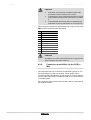
4.9.4.
Connection possibilities for the PCB (SCUS03)
If the boiler is fitted with the control PCB (SCU-S03), then this is
automatically recognised by the automatic control unit of the boiler.
X2
SCU-S03
CAUTION
On removing this PCB, the boiler will show fault code
e[38. To prevent this fault, an auto-detect must be
carried out after removing this PCB.
¼ See chapter: "Carrying out an auto-detect", page
62.
X2a
X1
Tsol
Tsol
Gps
Gps
Hru
Hru
T002879-A
n Pressure switch minimum (Gps)
The minimum gas pressure switch shuts the boiler down if the inlet
gas pressure becomes too low. Connect the minimum gas pressure
switch to the Gps terminals of the connector. The presence of the gas
pressure switch must be set using parameter p41.
n Heat Recovery Unit (Hru)
Connect the wires from the heat recovery unit to the Hru terminals of
the connector. The presence of the heat recovery unit must be set
using parameter p4".
4.9.5.
X2
SCU-X01
Connection possibilities for the PCB (SCUX01)
The control PCB SCU-X01 has two potential-free contacts, which can
be set as required. Depending on the setting, a maximum of two
messages about the status of the boiler can be transmitted. See table
below:
X2a
X3
X4
Status
Status
Nc C No
Nc C No
Nc C No
Nc C No
T002880-A
- 123157-AC
No. C-NO
C-NC
0
Alarm Standby
Alarm Active
1
Alarm inverted = fail safe Active Alarm inverted = fail safe Standby
2
Burning Standby
Burning Active
3
Burning inverted Active
Burning inverted Standby
4
Burning low Standby
Burning low Active
5
Burning high Standby
Burning high Active
6
Service report Standby
Service report Active
7
CH-mode Standby
CH-mode Active
8
DHW-mode Standby
DHW-mode Active
9
CH-pump Standby
CH-pump Active
39
4. Installation
Quinta Pro 30 - 45 - 65 - 90 - 115
4.9.6.
Jp1
X1
Connection possibilities for the PCB (SCUX02)
The connection options for the control PCB (SCU-X02) are described
in the paragraphs which follow.
1C2
F 2AT
X2
SCU-X02
X2a
X3
X4
3wV
NCD
3wV
3wV
NCD
N L C
N L C
T002884-A
n Control of external three-way valve (3wV (230 VAC)
The external three-way valve (230 VAC) can be used when
connecting an indirectly heated calorifier. The neutral position of the
three-way valve can be set using parameter p34.
The three-way valve X3 is connected to the X3 terminals of the
connector. The three-way valve is connected as follows:
4 N = neutral
4 C = central heating
4 D = domestic hot water
n Control of external three-way valve (3wV (24 VAC)
The external three-way valve (24 VAC) can be used when connecting
an indirectly heated calorifier. The neutral position of the three-way
valve can be set using parameter p34.
The three-way valve X4 is connected to the X4 terminals of the
connector. The three-way valve is connected as follows:
4 N = neutral
4 L = live (24 AC)
4 C = common (Central heating or DHW)
n Position of the reversal valve (JP1)
The position of the three-way valve can be set using a jumper at
JP1.
4 Jumper 1: The settings for central heating and sanitary hot water
are the default settings.
4 Jumper 2: The settings for central heating and sanitary hot water
are reversed.
40
- 123157-AC
Quinta Pro 30 - 45 - 65 - 90 - 115
4. Installation
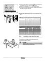
4.9.7.
X4
X3
The control PCB SCU-X03 can control a modulating central heating
pump. Depending on the make and type of pump, the pump can be
controlled by a 0-10 V, 4-20 mA or PWM signal. The speed of the
pump is modulated, based on the signal received from the boiler.
SCU-X03
X1
Connection possibilities for the PCB (SCUX03)
For correct connection of the pump, see the documentation
supplied with the pump.
X2
Ctrl
0 +
0 +
T002038-B
n Connect on/off contact
Connect the on/off contact of the central heating pump to the
connector X1.
CAUTION
Do not use the on/off contact to interrupt the power supply
to the pump.
n Connect central heating pump
The control system of the central heating pump is connected to
connector X2.
Select the type of signal that will be received from the boiler using the
rotary knob SW1 on the control PCB. See table below:
No. Description
- 123157-AC
0
Pump modulation signal
1
Required heat output of boiler
2
Current heat output of boiler
3
-
4
-
5
-
6
-
7
-
8
-
9
-
41
4. Installation
Quinta Pro 30 - 45 - 65 - 90 - 115
CAUTION
If possible, use the pump modulation signal. This
provides the most accurate pump control.
In positions 3 to 9 the control PCB receives no signal
from the boiler and the boiler responds as in position
0.
If the automatic burner unit does not support pump
modulation, the pump will behave as an on/off pump.
4
4
4
Select the type of signal that controls the pump using the rotary knob
SW2 on the control PCB. See table below:
No. Description
0
0-10 V (Wilo pump)
1
0-10 V (Grundfoss pump)
2
PWM
3
4-20 mA
4
-
5
-
6
-
7
-
8
-
9
-
CAUTION
In positions 4 to 9 the control PCB sends no signal to the
pump and the pump will not start up.
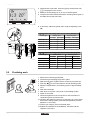
4.9.8.
Connection possibilities for the PCB (cMix)
The c-Mix print PCB can control two central heating groups or one
central heating group and one calorifier. These groups can be
controlled entirely independently of one another. It is also possible to
use the c-Mix control PCB in combination with one or more boilers in
a cascade system.
The connection options for the control PCB (c-Mix) are described in
the supplied manual.
42
- 123157-AC
Quinta Pro 30 - 45 - 65 - 90 - 115
4. Installation
4.10 Electrical diagram
X1
X2
X3
X4
X5
X6
X8
1 3 2
1 2 3
4 5 3 2 1
1 2 3
2 3 4 1
1 2 3
1 2 3
1
2 3 4 5
GY
BK
BL
GN/
YW
GN/
YW
WH
BL
GN/
YW
BR
BL
BK
BK
BK
BK
BK
BR
BL
BL
GN/YW
GN/
YW
BR
GN/
YW
BR
BL
BL
BR
GN/
YW
3 1
BR
BL
3 1 2
X9
BK
2 1 3
X81
3 1 2
3 5 1
X51
X21/X61
K1 1 2 3
3 1 2
SCU
X51 4 2
X41
1
1 2 4 5
IT
FAN
S
GB
X117
X41
X91
L N
PUMP A
FAN
P
230V, 50Hz
2
HLS
E
X10
1
2 3
BK
8
BL
9
10 11
RD BK
BK
1
1
X11
4 5 7 6
12 13
BK BK
BK
BK BK
BK
3 1
1 2 3 4 5 6
X12
1
2
3
4 5
OS
X3
X2 X4
X1
2
2
RTS FTS
X116
PSU
PWM
PUMP
2
8
1
1 10
9 10
1 10
OT
1 2
X111
7
X14
OR
YW
WH
RD
GY
GN
1 2 3 4
X114 X115 X112
6
X13
SCU
WS
PC
X5
X6
X7
X8
X9
X10
DIS
X11
PS
X14
X13 X12
T002602-C
Power supply
GB
Combined venturi and gas valve unit PSU Storage parameter
SCU Extended control PCB PUMP A Shunt pump
OT Thermostat
S
HLS
OS Outside sensor
On/Off switch
Safety thermostat
FAN Fan
IT
Ignition transformer
RTS
Return sensor
WS
DHW sensor
FTS
Flow sensor
PC
Connecting a computer
PS
Pressure sensor
DIS
Display
P
E
Ignition power relay
- 123157-AC
43
4. Installation
Quinta Pro 30 - 45 - 65 - 90 - 115
4.11 Filling the system
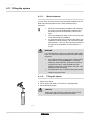
4.11.1.
Water treatment
In most cases, the boiler and the central heating installation can be
filled with normal tap water and no water treatment will be
necessary.
4
4
4
Rinse the central heating installation with at least 3x
the volume of the central heating installation. Flush
the DHW pipes with at least 20 the volume of the
pipes.
Use only untreated tap water to fill or top up the level
in the central heating installation.
For untreated water, the pH value of the water in the
installation must be between 7 and 9 and for treated
water between 7 and 8.5. The maximum hardness of
the water in the installation must be between 0.5 20ºdH.
WARNING
For more information, refer to our publication water quality
rules. The rules in the aforementioned document must be
respected.
4
4
4.11.2.
Do not add chemical products to the central heating
water without consulting Remeha. For example:
antifreeze, water softeners, products to increase or
reduce the pH value, chemical additives and/or
inhibitors. These may cause faults in the boiler and
damage the heat exchanger.
The temperature of the central heating pipes and the
radiators may reach 90À.
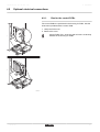
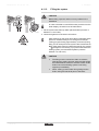
Filling the siphon
1. Remove the siphon.
2. Fill the siphon with water. This must be completely filled.
3. Re-assemble the siphon.
CAUTION
Fill the water siphon before starting the boiler to avoid
combustion products escaping from the boiler.
T002037-B
44
- 123157-AC
Quinta Pro 30 - 45 - 65 - 90 - 115
4. Installation
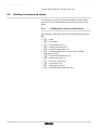
4.11.3.
Filling the system
CAUTION
Before filling, open the valves on every radiator in the
installation.
In order to be able to read off the water pressure from the
boiler display, the boiler must be switched on.
1
2
3
4
T000181-B
1. Fill the system with clean tap water (advised water pressure is
between 1.5 and 2 bar).
2. Check the tightness of the water connections.
T001507-A
After switching on the power and if there is adequate water
pressure, the boiler always runs through an automatic
venting program lasting approximately 3 minutes (During
filling, air can escape from the system via the automatic air
vent). If the water pressure is lower than 0.8 bar, the symbol
e will appear. If necessary, top up the water level in the
heating system (recommended hydraulic pressure
between 1.5 and 2 bar).
CAUTION
4
4
- 123157-AC
The filling must be carried out within 30 minutes,
otherwise the venting program starts and that would
be undesirable if the device is not filled. Switch off the
boiler if the central heating system is not being
topped up immediately.
When venting, prevent water from getting into the
boiler casing and electrical parts of the boiler
45
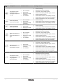
5. Start-up
Quinta Pro 30 - 45 - 65 - 90 - 115
5
Start-up
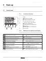
5.1
Control panel
5.1.1.
1
2
3
6
4
5
8
7
Functions of the keys
1
Display
2
> [Escape] or key J
3
D Heating temperature key or [-]
4
N DHW temperature key or [+]
5
S [Enter] or cancel d Key lock-out
6
B [Chimney-sweeping] keys
(press the 2 and 3 keys simultaneously)
7
f [Menu] keys
(press the 4 and 5 keys simultaneously)
8
a On/off switch
T001996-A
5.1.2.
Information menu:
Q Reading the various current values.
Meaning of the symbols on the display
a
On/Off switch:
After 5 lock-outs, the device must be switched off/on
again.
Chimney-sweeping position:
B Forced full or part load for CO measurement.
2
b
Shunt pump:
The pump operates.
User menu:
Parameters at user level can be changed.
D
Central heating function:
Access to central heating temperature parameter.
Heating programme deactivated:
The heating function is deactivated.
N
Sanitary hot water function:
Access to sanitary hot water temperature parameter.
W
C
E
Manual mode:
Boiler is set to manual operation.
T
DHW programme deactivated:
The DHW mode is deactivated.
?
Service menu:
Parameters at installer level can be changed.
)
46
Energy-saving mode:
Economic mode activated.
K
e
g
[
Yellow display with the symbols:
$ + K + Z (Maintenance message).
Water pressure:
The water pressure is too low.
Battery symbol:
Status of battery of wireless controller.
Signal strength symbol:
Signal strength of the wireless controller.
- 123157-AC
Quinta Pro 30 - 45 - 65 - 90 - 115
5. Start-up
Fault:
c Boiler indicates a fault. This can be seen from the e code
and red display.
]
Frost protection:
Boiler is running in frost protection mode.
I
d
Burner level:
Boiler is running at full or low load.
Locking the keys:
Key lock-out is activated.
Hour counter menu:
\ Readout of the operating hours, number of successful
starts and hours on mains supply.
5.2
Check points before commissioning
5.2.1.
Preparing the boiler for commissioning
WARNING
Do not put the boiler into operation if the supplied gas is
not in accordance with the approved gas types.
Preparatory procedure for boiler commissioning:
4 Check that the gas type supplied matches the data shown on the
boiler's data plate.
4 Check the gas circuit.
4 Check the hydraulic circuit.
4 Check the water pressure in the heating system.
4 Check the electrical connections to the thermostat and the other
external controls.
4 Check the other connections.
4 Test the boiler at full load. Check the setting of the gas/air ratio
and, if necessary, correct it.
4 Test the boiler at part load. Check the setting of the gas/air ratio
and, if necessary, correct it.
4 Finalizing work.
Complete the checklist.
¼ See chapter: "Checklist for commissioning", page
86.
5.2.2.
Gas circuit
WARNING
Ensure that the boiler is switched off.
1. Open the main gas supply.
2. Unscrew the two screws located under the front panel by a quarter
turn and remove the panel.
3. Tilt the control box forwards by opening the holding clips located
at the sides.
- 123157-AC
47
5. Start-up
Quinta Pro 30 - 45 - 65 - 90 - 115
4. Check the gas supply pressure at the measurement point C on the
gas valve unit.
WARNING
¼ To ascertain the gas types permitted, see chapter:
"Equipment categories", page 8
C
C
T003243-A
5. Check the tightness of the gas connections made after the gas
valve unit in the boiler.
6. Check the leak tightness of the gas inlet, including the gas
valves. The test pressure must not exceed 60 mbar.
7. Purge the gas supply pipe within the boiler by unscrewing the
measurement point on the gas block. Tighten the measurement
point when the pipe has been sufficiently purged.
8. Check the tightness of the gas connections in the boiler.
5.2.3.
Hydraulic circuit
4 Check the syphon — this must be completely filled with clean
water.
4 Check that there are no leaks on the hydraulic connections.
5.2.4.
Electrical connections
4 Check the electrical connections, particularly the earth.
4 Check the electrical connections to the thermostat and the other
external controls.
5.3
Putting the appliance into operation
WARNING
If adapting to another gas type i.e. propane, the gas valve
must be adjusted before switching on the boiler.
¼ See chapter: "Adapting to another gas type", page
50
1. Tilt the control box upwards again and fasten it using the clips
located at the sides.
2. Open the main gas supply.
3. Open the gas valve on the boiler.
4. Switch on the electrical supply.
5. Turn on the boiler using the on/off switch.
6. Set the controls (thermostats, control system) so that they request
heat.
48
- 123157-AC
Quinta Pro 30 - 45 - 65 - 90 - 115
5. Start-up
7. The start-up cycle begins and cannot be interrupted. During the
start-up cycle, the display shows the following information:
A short test where all segments of the display are visible.
fK[xx : Software version
pK[xx : Parameter version
The version numbers are displayed alternately.
8. A vent cycle of a duration of around 3 minutes is carried out
automatically.
If a DHW sensor is connected and the anti-legionella
function is activated, the boiler starts to heat the water in
the DHW tank as soon as the vent programme has been
completed.
By pressing the ® key for a short time, the current operating status
is shown on the display:
Heat demand 5tD
Heat demand stopped
1 : Fan ON
1 : Post-ventilation
" : Boiler is igniting 5 : Burner stop
6 : Post-circulation of the pump
3 : Heating System 0 : Standby
In addition to 0, in STAND-BY the display normally shows the water
pressure and the symbols 5tD, 5tH and N.
Error during the start-up procedure:
4 No information is shown on the display:
- Check the mains supply voltage
- Check the main fuses
- Check the fuses on the control panel:
(F1 = 6,3 AT, F2 = 2 AT)
- Check the connection of the mains lead to the connector X1 in
the instrument box
4 A fault is indicated on the display by the fault symbol c and a
flashing fault code.
- The meaning of the error codes is given in the error table.
- Press for 3 seconds on key J to restart the boiler.
If the economy setting (eco setting) is on, then, after central
heating operation, the boiler will not start to run for hot tap
water production.
- 123157-AC
49
5. Start-up
5.4
Quinta Pro 30 - 45 - 65 - 90 - 115
Gas settings
5.4.1.
Adapting to another gas type
WARNING
Only a qualified engineer may carry out the following
operations.
The boiler is preset in the factory to operate on natural gas G20 (Gas
H).
For operation on another group of gases, carry out the following
operations. In case of functioning on propane:
1.
Quinta Pro For conversion to propane
A
A
30
Rotate the adjusting screw A on the venturi 3½ turns in a
clockwise direction
45
Rotate the adjusting screw A on the venturi 4¾ turns in a
clockwise direction
65
Rotate the adjusting screw A on the venturi 6½ turns in a
clockwise direction
90
Fit the gas restrictor in the gas block
115
First turn the setting screw A clockwise until it is closed, then:
Rotate the adjusting screw A on the gas block 3,5 - 4 turns in
an anticlockwise direction
T003241-A
2. Regulate the fan speed as indicated in the table (if required). The
setting can be modified using parameters p17, p18,
p19 and p20:
¼ See chapter: "Description of the parameters", page 56
3. Set the air/gas ratio. For more detailed information:
¼ See chapter: "Setting the air/gas ratio (Full load)", page
50
¼ See chapter: "Setting the air/gas ratio (Part load)", page
51
5.4.2.
Setting the air/gas ratio (Full load)
1. Unscrew the plug of the flue gas measurement point.
2. Connect the flue gas analyser.
WARNING
Ensure that the opening around the sensor is completely
sealed when taking measurements.
CAUTION
T001581-A
50
The flue gas analyser must meet the requirements of BS
7927 or BS-EN 503793 and be calibrated according to the
manufacturer's requirements.
- 123157-AC
Quinta Pro 30 - 45 - 65 - 90 - 115
St
ºC
5. Start-up
3. Set the boiler to full load. Press the two B keys simultaneously.
The display shows h3. The symbol B appears.
4. Measure the percentage of O2 or CO2 in the flue gases.
ºCºFh
barPsi
rpm
kWµA
± 30l/min
5. Compare the values measured with the checking values given in
the table (Front panel removed).
T001997-A
6. If necessary, adjust the gas/air ratio using the adjusting screw
(A).
O2/ CO2 control and setting values at full load for G20 (Gas H)
Boiler type
A
A
T003241-A
Setting value
Checking value
O 2 (%)
CO 2 (%)
O 2 (%)
CO 2 (%)
Quinta Pro 30
4.8 ± 0.2
9.0 ± 0.1
4.8 ± 0.5
9.0 ± 0.2
Quinta Pro 45
4.8 ± 0.2
9.0 ± 0.1
4.8 ± 0.5
9.0 ± 0.2
Quinta Pro 65
4.8 ± 0.2
9.0 ± 0.1
4.8 ± 0.5
9.0 ± 0.2
Quinta Pro 90
3.9 ± 0.2
9.5 ± 0.1
3.9 ± 0.5
9.5 ± 0.2
Quinta Pro 115
4.7 ± 0.2
9.1 ± 0.1
4.7 ± 0.5
9.1 ± 0.2
O2/ CO2 control and setting values at full load for G31 (Propane)
Boiler type
Setting value
Checking value
O 2 (%)
CO 2 (%)
O 2 (%)
CO 2 (%)
Quinta Pro 30
4.8 ± 0.2
10.7 ± 0.1
4.8 ± 0.5
10.7 ± 0.2
Quinta Pro 45
4.8 ± 0.2
10.7 ± 0.1
4.8 ± 0.5
10.7 ± 0.2
Quinta Pro 65
4.8 ± 0.2
10.7 ± 0.1
4.8 ± 0.5
10.7 ± 0.2
Quinta Pro 90
4.8 ± 0.2
10.7 ± 0.1
4.8 ± 0.5
10.7 ± 0.2
Quinta Pro 115
4.9 ± 0.2
10.5 ± 0.1
4.9 ± 0.5
10.5 ± 0.2
5.4.3.
Setting the air/gas ratio (Part load)
1. Unscrew the plug of the flue gas measurement point.
2. Connect the flue gas analyser.
WARNING
Ensure that the opening around the sensor is completely
sealed when taking measurements.
T001581-A
- 123157-AC
51
5. Start-up
Quinta Pro 30 - 45 - 65 - 90 - 115
St
3. Set the boiler to part load. Press the [-] key several times until
l3 is displayed on the screen.
4. Measure the percentage of O2 or CO2 in the flue gases.
ºCºFh
barPsi
rpm
kWµA
± 30l/min
ºC
5. Compare the values measured with the checking values given in
the table (Front panel removed).
T001998-A
6. If necessary, adjust the gas/air ratio using the adjusting screw
(B).
B
O2/CO2 control and setting values at part load for G20 (Gas H)
Boiler type
Setting value
Checking value
O 2 (%)
CO 2 (%)
O 2 (%)
CO 2 (%)
Quinta Pro 30
4.8 ± 0.2
9.0 ± 0.1
4.8 ± 0.5
9.0 ± 0.2
Quinta Pro 45
4.8 ± 0.2
9.0 ± 0.1
4.8 ± 0.5
9.0 ± 0.2
Quinta Pro 65
4.8 ± 0.2
9.0 ± 0.1
4.8 ± 0.5
9.0 ± 0.2
Quinta Pro 90
3.9 ± 0.2
9.5 ± 0.1
3.9 ± 0.5
9.5 ± 0.2
Quinta Pro 115
4.7 ± 0.2
9.1 ± 0.1
4.7 ± 0.5
9.1 ± 0.2
O2/CO2 control and setting values at part load for G31 (Propane)
Boiler type
B
B
T003242-A
5.5
Setting value
Checking value
O 2 (%)
CO 2 (%)
O 2 (%)
CO 2 (%)
Quinta Pro 30
4.8 ± 0.2
10.7 ± 0.1
4.8 ± 0.5
10.7 ± 0.2
Quinta Pro 45
4.8 ± 0.2
10.7 ± 0.1
4.8 ± 0.5
10.7 ± 0.2
Quinta Pro 65
4.8 ± 0.2
10.7 ± 0.1
4.8 ± 0.5
10.7 ± 0.2
Quinta Pro 90
4.8 ± 0.2
10.7 ± 0.1
4.8 ± 0.5
10.7 ± 0.2
Quinta Pro 115
4.9 ± 0.2
10.5 ± 0.1
4.9 ± 0.5
10.5 ± 0.2
Finalizing work
1.
2.
3.
4.
5.
T001522-A
52
Remove the measuring equipment.
Put the flue gas sampling plug back in place.
Refit the front panel. Tighten the two screws by a quarter turn.
Push key > to return the boiler to normal operating mode.
Raise the temperature in the heating system to approximately
70°C.
6. Shut down the boiler.
7. After about 10 minutes, vent the air in the heating system.
8. Switch on the boiler.
9. Check the tightness of the connection for the evacuation of
combustion gases and the air inlet.
10.Checking the hydraulic pressure. If necessary, top up the water
level in the heating system (recommended hydraulic pressure
between 1.5 and 2 bar).
11.Tick the gas category used on the data plate.
12.Explain the operation of the installation, the boiler and the
regulator to the users.
- 123157-AC
Quinta Pro 30 - 45 - 65 - 90 - 115
5. Start-up
13.Give all the instruction manuals to the user.
5.6
Reading out measured values
The automatic control unit continuously measures various boiler
parameters. These parameters can be read off the boiler control
panel.
5.6.1.
Reading the various current values
The following current values can be read off the information menu
Q:
4 5t = State.
4 5v = Sub-status.
4 t1 = Flow temperature (°C).
4 t" = Return temperature (°C).
4 t3 = Calorifier temperature (°C).
4 t4 = Outside temperature (°C) (Only with an outside
temperature sensor).
4 t5 = Solar boiler temperature (°C).
4 5p = Internal set point (°C).
4 fl = Ionisation current (µA).
4 Mf = Fan speed in rpm.
4 pr = Water pressure (bar).
4 p; = Supplied relative heat output (%).
- 123157-AC
53
5. Start-up
Quinta Pro 30 - 45 - 65 - 90 - 115
The current values can be read as follows:
1. Press the two f keys simultaneously. The symbol Q flashes.
2. Confirm using key S. 5t is displayed, alternating with the
current status 3 (for example).
3. Press the [+] key. 5v is displayed, alternating with the current
sub-status 30 (for example).
4. Press the [+] key. t1 is displayed, alternating with the current
flow temperature 60°C (for example).
5. Press the [+] key successively to scroll down the various
parameters. t", t3, t4, t5 .
6. Press the [+] key. 5p is displayed, alternating with the internal
set point 88°C (for example).
7. Press the [+] key. fl is displayed, alternating with the current
ionisation current 70 µA (for example).
8. Press the [+] key. Mf is displayed, alternating with the current
fan rotation speed 3000 rpm (for example).
9. Press the [+] key. pr is displayed, alternating with the current
water pressure #0 bar (for example). If no water pressure sensor
is connected, [-.-] appears on the display.
10.Press the [+] key. p; is displayed, alternating with the current
modulation percentage 78 % (for example).
11.Press the [+] key. The readout cycle starts again with 5t.
12.Press 2 times on key > to return to the current operating mode.
4x
2x
T000810-F
5.6.2.
Readout from the hour counter and
percentage of successful starts
1. Press the two keys f simultaneously and then key [+] until the
symbol \ flashes on the menu bar.
2. Press the S key. hr and the number of hours of boiler
operation 3600 (for example) are displayed alternately.
3. Press the [+] key. The display shows D. hr is displayed,
alternating with the number of operating hours in central heating
operation 560 (for example).
4. Press the [+] key. The display shows N. hr is displayed,
alternating with the number of operating hours used for heating
tap water 320 (for example).
5. Press the [+] key. The display shows @. 5Z is displayed,
alternating with the percentage of successful starts 92 % (for
example).
6. Press 2 times on key > to return to the current operating mode.
5x
2x
T000816-G
54
- 123157-AC
Quinta Pro 30 - 45 - 65 - 90 - 115
5. Start-up
5.6.3.
Status and sub-status
The information menu Q gives the following status and sub-status
numbers:
State 5t
0
Rest
1
Boiler start (Heat demand)
Sub-status 5v
0 Rest
1 Anti-hunting
2 Control three-way valve
3 Start pump
2
Burner start
4 Wait for the correct temperatures for burner start
10 Open flue gas damper/external gas valve
11 Increase fan speed
13 Pre-ventilation
14 Wait for release signal
15 Burner on
17 Pre-ignition
18 Main ignition
19 Flame detection
"0 Intermediate ventilation
3 / 4 Burning for central heating operation 30 Temperature control
31 Limited temperature control (ΔT Safety)
32 Output control
33 Increase protection level 1 (Modulate down)
34 Increase protection level 2 (part load)
35 Increase protection level 3 (Blockage)
36 Modulate up for flame control
37 Temperature Stabilisation time
38 Cold start
5
Burner stop
40 Burner off
41 Post ventilation
42 Close flue gas damper/external gas valve
43 Recirculation protection
6
Boiler stop (End of heat demand)
44 Stop fan
60 Pump post circulation
61 Pump off
62 Control three-way valve
8
Stop
63 Start anti-hunting
0 Wait for burner start
9
Lock-out
xx Shutdown code xx
17
Bleed
1 Anti-hunting
0 Rest
2 Control three-way valve
3 Start pump
61 Pump off
62 Control three-way valve
- 123157-AC
55
5. Start-up
5.7
Quinta Pro 30 - 45 - 65 - 90 - 115
Changing the settings
The boiler control panel is set for the most common heating
systems. With these settings, practically all heating systems operate
correctly. The user or installer can optimise the parameters according
to own preferences.
For operation in open vented systems, several parameter settings
must be adjusted. Set the various parameters according to the values
given in the table below.
5.7.1.
Description of the parameters
Factory setting
Parameter
Description
Adjustment range
Quinta Pro
30 45 65 90 115
p1
Flow temperature: TSET
20 to 90 °C
p1
Open vented:
Flow temperature: TSET
20 to 90 °C
p2
Domestic hot water temperature:
TSET
40 to 65 °C
80
75
55
p3
Heating / DHW mode
0 = Heating deactivated / DHW deactivated
1 = Heating activated / DHW activated
2 = Heating activated / DHW deactivated
3 = Heating deactivated / DHW activated
p4
Mode ECO
0 = Comfort
1 = Energy-saving mode
2 = Management using a programmable thermostat
2
Anticipation resistance
0 = No anticipation resistance for the ON/OFF
thermostat
1 = Anticipation resistance for the ON/OFF
thermostat
0
p6
Display screen
0 = Simple
1 = Comprehensive
2 = Automatic switching to simple after 3 minutes
3 = Automatic switching to simple after 3 minutes ;
Key blocking is active
2
p7
Post-circulation of the pump
1 to 98 minutes
99 minutes = continuous
3
p8
Brightness of display lighting
0 = Dimmed
1 = Bright
1
p5
p17
p18
Maximum fan speed (Heating)
Maximum fan speed (DHW)
1
G20 (Natural gas)(1)
(x100 rpm)
41 54 58 62
70
G31 (Propane)
(x100 rpm)
36 54 58 60
67
G20 (Natural gas)(1)
(x100 rpm)
41 54 58 62
70
G31 (Propane)
(x100 rpm)
36 54 58 60
67
(1) Do not modify these factory settings unless absolutely necessary. E.g. to adapt the boiler to: G31 (Propane)
56
- 123157-AC
Quinta Pro 30 - 45 - 65 - 90 - 115
5. Start-up
Factory setting
Parameter
Description
Adjustment range
Quinta Pro
30 45 65 90 115
p19
p19
p20
p20
Minimum fan speed (Heating
+DHW)
Open vented:
Minimum fan speed (Heating
+DHW)
Minimum fan speed (offset)
Open vented:
Minimum fan speed (offset)
G20 (Natural
(x100 rpm)
gas)(1)
16 16 16 15
18
G31 (Propane)
(x100 rpm)
18 16 16 22
25
G20 (Natural gas)(1)
(x100 rpm)
16 16 16 15
18
G31 (Propane)
(x100 rpm)
18 16 16 22
18
G20 (Natural gas)(1)
(x100 rpm)
0
0
0
50
0
G31 (Propane)
0
0
0
50
0
0
0
0
50
0
0
0
0
50
0
G20 (Natural
(x100 rpm)
gas)(1)
G31 (Propane)
p21
Start speed
Do not modify
(x100 rpm)
p21
Open vented:
Start speed
Do not modify
(x100 rpm)
25
p22
Minimum water pressure
0 - 3 bar(x 0.1 bar)
8
p23
Maximum flow temperature of
system
0 to 90 °C
p24
Anti-hunting differential for central -15 to 15 °C
heating operation
3
p25
Heat curve set point
(Maximum outside temperature)
0 to 30 °C
(Only with an outside temperature sensor)
20
p26
Heat curve set point
(Flow temperature)
0 to 90 °C
(Only with an outside temperature sensor)
20
p27
Heat curve set point
(Minimum outside temperature)
-30 to 0 °C
(Only with an outside temperature sensor)
-15
p28
Minimum pump speed for central
heating operation Setting the
pump speed
2 - 10 (x 10 % )
p29
Maximum pump speed for central 2 - 10 (x 10 % )
heating operation Setting the
pump speed
10
p30
Antifreeze temperature
from - 30 to 0°C
-10
p31
Legionella protection
0 = Stop
1 = Start
(After commissioning, the boiler will operate once a
week at 65°C for DHW)
3 = Management using a programmable thermostat
1
p32
Set point increase for calorifier
0 to 20 °C
20
p33
DHW cut-in temperature DHW
sensor
from 2 to 15°C
5
p34
Control of three-way valve
0 = Normal
1 = Reverse
0
p35
Boiler type
0 = Heating only
1 = Open vented
0
Shutdown input function
0 = Heating activated
1 = Shutdown without frost-protection
2 = Shutdown with frost protection
3 = Lock-out with frost protection (Pump only)
1
p36
25
90
4
(1) Do not modify these factory settings unless absolutely necessary. E.g. to adapt the boiler to: G31 (Propane)
- 123157-AC
57
5. Start-up
Quinta Pro 30 - 45 - 65 - 90 - 115
Factory setting
Parameter
Description
Adjustment range
Quinta Pro
p37
Release function
0 = Hot water on
1 = Release input
1
p38
Release waiting time
0 to 255 seconds
0
p39
Gas valve switching time
0 to 255 seconds
0
p40
Fault relay function (Optional)
0 = Operation signal
1 = Alarm signal
1
p41
GpS connected (Optional)
0 = Not connected
1 = Connected
0
p42
HRU connected (Optional)
0 = Not connected
1 = Connected
0
p43
Mains detection phase
0 = Stop
1 = Start
0
p44
Maintenance message
Do not modify
1
p45
Service operating hours
Do not modify
175
p46
Service burning hours
Do not modify
30
Detection of connected SCUs
0 = No detection
1 = Detection
0
30 45 65 90 115
Zd
df and dV Factory setting
To restore the factory settings or when replacing the
main PCB, enter the values dF and dU from the type
plate in parameters df and dV
X
Y
(1) Do not modify these factory settings unless absolutely necessary. E.g. to adapt the boiler to: G31 (Propane)
5.7.2.
Modification of the user-level parameters
Parameters p1 to p8 can be modified by the user in order to meet
central heating and DHW comfort needs.
CAUTION
Modification of the factory settings may be detrimental to
the functioning of the boiler.
1. Press the two keys f simultaneously and then key [+] until the
symbol W flashes on the menu bar.
2. Select the users menu using the key S. p[1 is displayed with
1 flashing.
3. Press the S key a second time. .
4. Change the value by pressing the [-] or [+] key. In this example
using key [-] to 60°C.
5. Confirm the value with the S key. p[1 is displayed with 1
flashing.
6. Press 2 times on key > to return to the current operating mode.
The parameters p1 to p8 are changed in the same way
as p1. After step 2, use the [+] key to move to the
required parameter.
58
- 123157-AC
Quinta Pro 30 - 45 - 65 - 90 - 115
5. Start-up
5.7.3.
Modification of the installer-level
parameters
Parameters p17 to df must only be modified by a qualified
professional. To prevent unwanted settings, some parameter settings
can only be changed after the special access code 0012 is
entered.
CAUTION
Modification of the factory settings may be detrimental to
the functioning of the boiler.
1. Press the two keys f simultaneously and then key [+] until the
symbol ? flashes on the menu bar.
2. Select the fitter menu using the ® key. c0de appears on the
display.
Use keys [-] or [+] to input the installer code 0012.
Confirm using key S. p[1 is displayed with 1 flashing.
Press the S key a second time. .
Change the value by pressing the [-] or [+] key. In this example
using key [-] to 60°C.
7. Confirm the value with the S key: p[1 is displayed with 1
flashing.
8. If necessary, set other parameters by selecting them using the
[-] or [+] keys.
9. Press 2 times on key > to return to the current operating mode.
3x
3.
4.
5.
6.
The boiler also returns to operating status if no keys are
pressed for 3 minutes.
2x
T000819-E
5.7.4.
Quinta Pro 30
35
M
30
F
25
20
Q
M
Maximum heat input
F
Factory setting
Q
Power input (kW)
R
Fan rotation speed (rpm)
15
10
5
0
1500
Setting the maximum heat input for central
heating operation
2000
2500
3000
3500
4000
R
4500
4400
5000
5500
6000
4100
T000630-B
- 123157-AC
59
5. Start-up
Quinta Pro 30 - 45 - 65 - 90 - 115
Quinta Pro 45
45
M
41
40
F
35
30
Q
M
Maximum heat input
F
Factory setting
Q
Power input (kW)
R
Fan rotation speed (rpm)
25
20
15
10
5
0
1500
2000
2500
3000
3500
4000
4500
R
5000
5500
6000
5400
5200
T000631-B
Quinta Pro 65
M
62
60
F
M
Maximum heat input
F
Factory setting
Q
Power input (kW)
R
Fan rotation speed (rpm)
45
Q
30
15
0
1500
2000
2500
3000
3500
4000
4500
5000
5500
6000 6500
6200
5800
T000632-B
R
Quinta Pro 90
100
M
86
80
F
M
Maximum heat input
60
F
Factory setting
40
Q
Power input (kW)
20
R
Fan rotation speed (rpm)
Q
0
1500
2500
3500
4500
5500
R
6500
6200
7500
T000633-B
Quinta Pro 115
120
M
110
F
100
M
Maximum heat input
F
Factory setting
60
Q
Power input (kW)
40
R
Fan rotation speed (rpm)
80
Q
20
0
1500
2500
3500
4500
R
5500
6500
7500
7000
See the graphs for the relationship between heat input and speed for
natural gas. The speed can be changed using parameter p17. To
do this, proceed as follows:
T000634-B
60
- 123157-AC
Quinta Pro 30 - 45 - 65 - 90 - 115
5. Start-up
1. Press the two keys f simultaneously and then key [+] until the
symbol ? flashes on the menu bar.
2. Select the installers menu using the key S. c0de appears
on the display.
3. Use keys [-] or [+] to input the installer code 0012.
4. Confirm using key S. p[1 is displayed with 1 flashing.
5. Press the [+] key to go to parameter p[17.
6. Confirm using key S.
7. Press the [+] key to increase the speed from 46 to, for example,
50 (see the graphs for the associated heat output).
8. Confirm the value with the S key.
9. Press 2 times on key > to return to the current operating mode.
3x
...x
...x
2x
T001628-A
5.7.5.
Return to the factory settings "Reset
Param"
1. Press the two keys f simultaneously and then key [+] until the
symbol ? flashes on the menu bar.
2. Select the installers menu using the key S. c0de appears
on the display.
3. Use keys [-] or [+] to input the installer code 0012.
4. Confirm using key S. p[1 is displayed with 1 flashing.
5. Press the [+] key several times. p[df is displayed with df
flashing.
6. Press the S key. df[x is displayed with x flashing. This is
the current value of X for dF. Check this against the value of X on
the type plate.
7. Enter the value of X shown on the type plate using the [-] or [+]
key.
8. Confirm the value with the S key, df[y is displayed with y
flashing. This is the current value of Y for dU. Check this against
the value of Y on the type plate.
9. Enter the value of Y shown on the type plate using the [-] or [+]
key.
10.Confirm the value with the S key. The factory settings are reset.
11.The display returns to the current operating mode.
3x
...x
T000820-H
- 123157-AC
61
5. Start-up
Quinta Pro 30 - 45 - 65 - 90 - 115
5.7.6.
Carrying out an auto-detect
After removing a control PCB, an auto-detect must be carried out. To
do this, proceed as follows:
1. Press the two keys f simultaneously and then key [+] until the
symbol ? flashes on the menu bar.
2. Select the installers menu using the key S. c0de appears
on the display.
3. Use keys [-] or [+] to input the installer code 0012.
4. Confirm using key S. p[1 is displayed with 1 flashing.
5. Press the [+] key several times. p[Zd is displayed with Zd
flashing.
6. Confirm using key S. Auto-detect is carried out.
7. The display returns to the current operating mode.
3x
...x
T000445-B
5.7.7.
In some cases it may be necessary to switch the boiler to manual
operation, For example, if the controller has not yet been
connected. The boiler can be switched to automatic or manual
operation under the symbol E. To do this, proceed as follows:
2x
bar
2x
T000824-E
62
Setting the manual mode
1. Press the two keys f simultaneously and then key [+] until the
symbol E flashes on the menu bar.
2. Press the S key:
or
The text Zv with the current water pressure (only if an outside
sensor is connected). The flow temperature is determined by the
internal heating curve.
or
The value of the minimum flow temperature.
3. Press the [-] or [+] key to increase this value temporarily in manual
operation.
4. Confirm the value with the S key. The boiler is now set to manual
operation.
5. Press 2 times on key > to return to the current operating mode.
- 123157-AC
Quinta Pro 30 - 45 - 65 - 90 - 115
6. Switching off the appliance
6
Switching off the appliance
6.1
Installation shutdown
If the central heating system is not used for a long period, we
recommend switching the boiler off.
4 Switch the On/Off switch on Off.
4 Isolate the gas supply.
4 Ensure that the boiler and system are protected against frost
damage.
6.2
Frost protection
CAUTION
Drain the boiler and central heating system if you are not
going to use your home or the building for a long time and
there is a chance of frost.
4 Set the temperature control low, for example at 10°C.
To prevent radiators and the system from freezing in rooms where
there is a risk of frost (e.g. a garage or storage room), a frost
thermostat or outside sensor can be connected to the boiler.
¼ See chapter: "Connect frost protection", page 32.
CAUTION
4
4
The anitfreeze protection does not function if the
boiler is switched off.
The integrated protection system only protects the
boiler, not the installation.
When the heating water temperature in the boiler falls by too much,
the integrated protection system in the boiler starts up. This protection
functions as follows:
4 If the water temperature is lower than 7°C, the heating pump starts
up.
4 If the water temperature is lower than 4°C, the boiler starts up.
4 If the water temperature is higher than 10°C, the boiler shuts down
and the heating pump continues to run for a short time.
- 123157-AC
63
7. Checking and maintenance
Quinta Pro 30 - 45 - 65 - 90 - 115
7
Checking and maintenance
7.1
Maintenance message
Boiler maintenance is kept to a minimum. Nevertheless, we
recommend having the boiler inspected and serviced at regular
intervals. To determine the best time for maintenance operations, the
boiler is fitted with a function that automatically signals any
maintenance to be carried out. The appearance if this service
message on the boiler display is determined by the automatic control
unit. Depending on the use of the boiler, the first maintenance
message appears 3 years after installation of the boiler at the latest.
WARNING
4
Maintenance operations must be done by a qualified
engineer.
An annual inspection is compulsory.
4
Only original spare parts must be used.
4
7.2
Preventive maintenance with automated "service message"
When it is time to carry out maintenance on the boiler, the following
instructions are shown on the display:
In a yellow display:
4 The symbol ?
4 The symbol K
4 Maintenance message Z , B or c
Thanks to the automatically transmitted maintenance message, it is
possible to carry out preventive maintenance and therefore use the
maintenance kits defined by Remeha, thus reducing breakdowns to
a minimum. The maintenance message indicates which kit should be
used. These maintenance kits (A, B or C) are available from your
spare parts supplier. If no other errors are noted during the inspection
initiated subsequent to the maintenance message, these
maintenance kits include all of the parts needed for the maintenance
concerned (such as the gaskets, for example).
4
4
64
When a maintenance message is displayed, it must
be acted upon within the 2 months following the
appearance of the message.
If the iSense modulating controller is connected to the
device, then this service message is also passed to
the iSense. In this way, the end user is requested to
contact the installation company. See also the manual
for the iSense controller.
- 123157-AC
Quinta Pro 30 - 45 - 65 - 90 - 115
7. Checking and maintenance
CAUTION
Reset the maintenance message to zero after each
inspection.
7.2.1.
Resetting the automatic maintenance
message
A service message on the boiler display must be reset by a qualified
installer after the maintenance service has been carried out using the
relevant service set. To do this, proceed as follows:
1. When the maintenance message is displayed, press key J1
time. c0de appears on the display.
2. Use keys [-] or [+] to input the installer code 0012.
3. Confirm using key S. The maintenance message is reset. The
display returns to the current operating mode.
1x
T001629-A
7.2.2.
Dealing with the next maintenance
message and starting the new maintenance
period
For an interim service it is advisable to read out in the boiler service
menu what maintenance service should be carried out. Use the
indicated Remeha service sets (A, B or C). This service message
must be prevented by carrying out a reset. Start the next service
interval. To do this, proceed as follows:
5x
1. Press the two keys f simultaneously and then key [+] until the
symbol \ flashes on the menu bar.
2. Press the S key. hr and the number of hours of boiler
operation 3600 (for example) are displayed alternately.
3. Press key [+] several times until K flashes on the menu bar.
4. Press the S key. c0de appears on the display.
5. Use keys [-] or [+] to input the installer code 0012.
6. Confirm using key S.
7. Press key [+] several times until 5c[B is displayed with B (for
example) flashing To determine the best time to carry out
maintenance, the boiler is fitted with a single automatic
maintenance indicator.
8. Press the [+] key a second time. cl appears on the display.
9. Press the S key. cl[0 is displayed with 0 flashing.
10.Press key [+] to modify the value to 1.
11.Confirm using key S. The new maintenance period begins.
12.Press 3 times on key > to return to the current operating mode.
...x
...x
After a service complete the checklist.
¼ See chapter: "Checklist for periodic inspection and
maintenance", page 87.
3x
T001630-A
- 123157-AC
65
7. Checking and maintenance
7.3
Quinta Pro 30 - 45 - 65 - 90 - 115
Standard inspection and maintenance operations
CAUTION
During inspection and maintenance operations, always
replace all gaskets on the parts removed.
7.3.1.
Checking the hydraulic pressure
The hydraulic pressure must reach a minimum of 0.8 bar. For open
vented systems, the water pressure must be at least 0.3 bar (Q30/
Q45/Q65/Q90) or 0.5 bar (Q115) bar. If the water pressure is too low,
the symbol e will appear.
If necessary, top up the water level in the heating system
(recommended hydraulic pressure between 1.5 and 2 bar).
7.3.2.
Checking the ionisation current
Check the ionisation current at full load and low load. The value is
stable after 1 minute. If the value is less than 4 µA, clean or replace
the ignition electrode.
¼ See chapter: "Reading the various current values", page 53.
7.3.3.
Checking the tightness of the combusted
gases evacuation and air inlet connections
Check the tightness of the connection for the evacuation of
combustion gases and the air inlet.
T001580-A
66
- 123157-AC
Quinta Pro 30 - 45 - 65 - 90 - 115
7. Checking and maintenance
7.3.4.
Checking combustion
The check on combustion is done by measuring the percentage of
O2/CO2 in the flue gas discharge flue. To do this, proceed as follows:
1. Unscrew the plug of the flue gas measurement point.
2. Connect the flue gas analyser.
CAUTION
Ensure that the opening around the sensor is completely
sealed when taking measurements.
T001581-A
3. Set the boiler to full load. Press the two B keys simultaneously.
The B symbol is visible on the menu bar and h3 appears in the
display. The boiler is now operating at full load.
4. Measure the percentage of CO2 and compare this value with the
checking values given.
¼ See chapter: "Setting the air/gas ratio (Full load)", page
50.
5. Set the boiler to part load. Press the [-] key several times until
l3 is displayed on the screen. The boiler is now operating on
part load.
6. Measure the percentage of CO2 and compare this value with the
checking values given.
¼ See chapter: "Setting the air/gas ratio (Part load)", page
51.
...x
T001631-B
7.3.5.
1.
2.
3.
4.
Checking the automatic air vent
Switch off the boiler electrical power supply.
Close the gas valve on the boiler.
Close the main gas inlet valve.
Unscrew the two screws located under the front panel by a quarter
turn and remove the panel.
2
90º
1
T001514-A
- 123157-AC
67
7. Checking and maintenance
Quinta Pro 30 - 45 - 65 - 90 - 115
5. Tilt the control box forwards by opening the holding clips located
at the sides.
2
1
1
T001991-A
6. Check whether there is any water in the small hose on the
automatic air vent.
7. If any leaks are detected, replace the air vent.
T001582-A
7.3.6.
Checking the siphon
1. Remove the siphon and clean it.
2. Fill the siphon with water.
3. Put the siphon back in place.
68
- 123157-AC
Quinta Pro 30 - 45 - 65 - 90 - 115
7. Checking and maintenance
7.3.7.
Checking the burner and cleaning the heat
exchanger
CAUTION
4
During inspection and maintenance operations, always
replace all gaskets on the parts removed.
3
1.
2.
3.
4.
5.
6.
7.
Remove the air inlet flue on the venturi.
Loosen the union on the gas block.
Remove the plugs from the fan.
Remove the plugs from the gas block.
Remove the ignition electrode plug from the ignition transformer.
Remove the front plate from the heat exchanger
Carefully lift the front plate including the burner and fan from the
heat exchanger.
8. Use a vacuum cleaner fitted with a special endpiece (accessory)
to clean the top part of the heat exchanger (combustion chamber).
9. Thoroughly clean with the vacuum cleaner again without the top
cleaning brush on the endpiece.
10.Check (using a mirror, for example) whether any dust can still be
seen. If so, hoover it up.
11.Clean the lowermost part of the heat exchanger with the special
cleaning knife (accessory).
12.The burner does not require any maintenance, it is self-cleaning.
If necessary, clean the cylindrical burner using compressed air
Check that there are no cracks and/or other tears on the surface
of the dismantled burner. If this is not the case, replace the burner.
13.Checking the ignition electrode / ionization sensor.
14.To re-assemble, perform the above actions in reverse order.
5
2
1
8
9
11
CAUTION
10
12
4
Remember to reconnect the connector to the fan.
4
Check that the gasket is correctly positioned between
the mixing elbow and the heat exchanger.
(Completely flat in the appropriate groove means it is
leak proof).
15.Open the gas inlet valves and switch on the mains supply to the
boiler.
7
13
6
T002871-B
- 123157-AC
69
7. Checking and maintenance
7.4
Quinta Pro 30 - 45 - 65 - 90 - 115
Specific maintenance operations
If the standard inspection and maintenance operations have revealed
the necessity to carry out additional maintenance work, proceed as
follows, depending on the nature of the work:
7.4.1.
Inspection of the ignition electrode
1. Remove the ignition electrode plug from the ignition transformer.
The ignition cable is fixed to the ignition electrode and
therefore may not be removed.
4
2.
3.
4.
5.
6.
3
2
Unscrew the 2 screws. Remove the unit.
Wipe off all traces of deposits using an abrasive cloth.
Check the ignition electrode for wear. Replace if necessary.
Check the gasket.
Refit all parts, replacing those that are damaged.
1
T002872-A
70
- 123157-AC
Quinta Pro 30 - 45 - 65 - 90 - 115
7. Checking and maintenance
7.4.2.
Replacing the non-return valve
Replace the nonreturn valve when faulty or when the maintenance kit
contains one. To do this, proceed as follows:
1.
2.
3.
4.
5.
6.
7.
Remove the air inlet flue on the venturi.
Loosen the union on the gas block.
Remove the plugs from the fan.
Remove the ignition electrode plug from the ignition transformer.
Dismantle the fan.
Completely remove the fan/mixing elbow unit.
Replace the nonreturn valve located between the mixing elbow
and the fan.
8. To re-assemble, perform the above actions in reverse order.
3
4
1
2
5
7
2x
6
8
T002873-C
- 123157-AC
71
7. Checking and maintenance
Quinta Pro 30 - 45 - 65 - 90 - 115
7.4.3.
Assembling the boiler
1. Follow the procedure in reverse to re-assemble all of the
components.
CAUTION
During inspection and maintenance operations, always
replace all gaskets on the parts removed.
2. Fill the siphon with water.
3. Put the siphon back in place.
4. Carefully open the main water valve, fill the installation, vent it and,
if need be, top it up with water.
5. Check the seals on the gas and water connections.
6. Switch the boiler back on.
T002874-C
After a service complete the checklist.
¼ See chapter: "Checklist for periodic inspection and
maintenance", page 87.
72
- 123157-AC
Quinta Pro 30 - 45 - 65 - 90 - 115
8. Troubleshooting
8
Troubleshooting
8.1
Error codes
The boiler is fitted with an electronic regulation and control unit. The
heart of the control system is a microprocessor, the Comfort
Master©, which controls the boiler and also protects the boiler. If a
fault is detected anywhere in the boiler, the boiler locks out and the
display will show the fault code as follows:
In a red flashing display:
4 The symbol c
4 The symbol J
4 The fault code (for example e[01)
The meaning of the error codes is given in the error table. To do this,
proceed as follows:
4 Note the error code displayed.
.
4 Press key J for 2 seconds. If the error code continues to
display, search for the cause in the error table and apply the
solution.
If the display does not show J but rather a, the boiler
must be switched off and then switched on again after 10
seconds before the fault can be reset.
Error
code
Description
Probable causes
e[00
Storage unit PSU
parameter not found
e[01
The safety parameters
are incorrect
e[02
4
Flow temperature sensor 4
short circuited
4
e[03
4
Bad connection
4
Check the wiring
4
Bad connection
4
Check the wiring
4
PSU defective
Bad connection
4
4
Replace PSU
Check the wiring
Sensor fault
4
Check that the sensors are operating correctly
Sensor not or badly
connected
4
Check that the sensor has been correctly fitted
Bad connection
4
4
Replace the sensor if necessary
Check the wiring
Sensor fault
4
Check that the sensors are operating correctly
Sensor not or badly
connected
4
Check that the sensor has been correctly fitted
4
Replace the sensor if necessary
4
Flow temperature sensor 4
open circuit
4
- 123157-AC
Checking / solution
73
8. Troubleshooting
Error
code
Description
Quinta Pro 30 - 45 - 65 - 90 - 115
Probable causes
4
e[04
e[05
e[06
e[07
e[08
e[09
Temperature of heat
4
exchanger too low
Exchanger temperature 4
too high
4
Return temperature
sensor short circuited
Return temperature
sensor open circuit
Return temperature too
low
Return temperature too
high
Difference between the
flow and return
temperatures too great
74
Sensor not or badly
connected
No circulation
Bad connection
4
Sensor fault
4
4
Sensor not or badly
connected
Bad connection
4
Sensor fault
4
Sensor not or badly
connected
4
Bad connection
4
Sensor fault
4
Sensor not or badly
connected
No circulation
4
Check the wiring
4
Replace the sensor if necessary
4
Vent the air in the heating system
4
Check the circulation (direction, pump, valves)
4
Check the water pressure
4
Check that the sensors are operating correctly
4
Check that the sensor has been correctly fitted
4
Check the cleanliness of the heat exchanger
4
Check the wiring
4
Check that the sensor has been correctly fitted
4
Check that the sensors are operating correctly
4
Check the wiring
4
Check that the sensor has been correctly fitted
4
Check that the sensors are operating correctly
4
Check the wiring
4
Replace the sensor if necessary
4
Vent the air in the heating system
4
Check the circulation (direction, pump, valves)
4
Check the water pressure
4
Check that the sensors are operating correctly
4
Check that the sensor has been correctly fitted
4
4
Check the cleanliness of the heat exchanger
Replace the sensor if necessary
4
Vent the air in the heating system
4
Sensor fault
4
Check the circulation (direction, pump, valves)
4
Sensor not or badly
connected
No circulation
4
Check the water pressure
4
Check that the sensors are operating correctly
4
Check that the sensor has been correctly fitted
4
Check the cleanliness of the heat exchanger
4
4
Check that the heating pump is operating correctly
Check the wiring
4
Replace the sensor if necessary
4
Vent the air in the heating system
4
Check the circulation (direction, pump, valves)
4
Check the water pressure
4
Check that the sensors are operating correctly
4
Check that the sensor has been correctly fitted
4
Check the cleanliness of the heat exchanger
4
4
e[12
Sensor fault
4
4
e[10
e[11
Bad connection
Checking / solution
Temperature of heat
4
exchanger above normal
4
range (high-limit
thermostat STB)
4
Bad connection
Sensor fault
Sensor not or badly
connected
No circulation
- 123157-AC
Quinta Pro 30 - 45 - 65 - 90 - 115
Error
code
Description
8. Troubleshooting
Probable causes
4
e[14
5 burner start-up failures 4
4
4
e[16
False flame signal
4
4
Absence of ignition arch
Checking / solution
4
Check cabling of ignition transformer
4
Check the ionisation/ignition electrode
4
Check breakdown to earth
4
Check the condition of the burner set
4
Check the earthing
4
4
Defective control SU PCB
Purge the gas supply to remove air
4
Check that the gas valve is fully opened
4
Presence of the ignition
4
arc but no flame
4
formation
4
The burner remains very
hot: CO2 too high
Check the operation and setting of the gas valve unit
4
Check that the air inlet and flue gas discharge flues
are not blocked
Check the wiring on the gas valve unit
4
4
Defective control SU PCB
Check that the gas valve is fully opened
Presence of the flame 4
but insufficient ionization 4
(<3 µA)
4
Ionisation current
present when there
should not be a flame
Ignition transformer
defective
Gas valve defective
Check the supply pressure
Check the supply pressure
Check the ionisation/ignition electrode
Check the earthing
4
Check the wiring on the ionisation/ignition electrode
4
Check the ionisation/ignition electrode
4
Check the gas valve and replace if necessary
4
Set the CO2
e[17
Problem on the gas
valve SU PCB
4
Bad connection
4
Check the wiring
4
Defective SU PCB
Fan fault
Bad connection
Inspect the SU PCB and replace it if need be
Check the wiring
e[34
4
4
4
4
Fan defective
4
Replace the fan if need be
4
Check for adequate draw on the chimney connection
4
Bad connection
4
Sensor fault
4
Replace the sensor if necessary
Sensor not or badly
connected
Water circulation
direction reversed
4
Check the circulation (direction, pump, valves)
4
Check that the sensors are operating correctly
4
Check that the sensor has been correctly fitted
4
Purge the gas supply to remove air
4
Check that the gas valve is fully opened
4
Check the supply pressure
4
Check the operation and setting of the gas valve unit
4
Check that the air inlet and flue gas discharge flues
are not blocked
Check that there is no recirculation of flue gases
e[35
Flow and return reversed 4
4
e[36
5x Flame loss
4
No ionization current
4
e[37
Communication error
with the SU PCB
- 123157-AC
4
Bad connection
4
Check whether the SU PCB has been correctly fitted
in the connector on PCU PCB
75
8. Troubleshooting
Error
code
Quinta Pro 30 - 45 - 65 - 90 - 115
Description
Probable causes
e[38
Communication error
with the SCU PCB
e[39
Shutdown input in
locked-out mode
e[40
4
Bad connection
4
Check the wiring
4
4
Defective SCU PCB
Bad connection
4
4
Replace SCU PCB
Check the wiring
4
External cause
4
Suppress the external cause
4
4
Parameter incorrectly set 4
Bad connection
4
Check the parameters
Check the wiring
External cause
Suppress the external cause
HRU/URC unit test error 4
4
8.2
Checking / solution
4
Parameter incorrectly set 4
Check the parameters
Shutdowns and lock-outs
8.2.1.
Blockage
If the blocking conditions still exist after several start up attempts, the
boiler will switch into locking mode (fault). The boiler can only start
operating again once the causes of the lock-out have been rectified
and after pressing the > key.
8.2.2.
Lock-out
A (temporary)blocking mode is a boiler operating function caused by
an unusual situation. In this case, the display gives a code of blocking
(code 5t[9). The boiler control will try to re-start several times.
The boiler will start up again after the blocking conditions have been
eliminated. The shutdown codes can be read out as follows:
1. Press the two f keys simultaneously.
2. Confirm by pressing key S. 5t is displayed, alternating with
the shutdown code 9.
3. Press the [+] key. 5v appears on the display.
The boiler starts up again automatically when the reason
for the blocking has been removed.
T001632-B
76
- 123157-AC
Quinta Pro 30 - 45 - 65 - 90 - 115
8. Troubleshooting
Shutdown
code
Description
5v[0
Parameter error
4
5v[1
Maximum flow temperature
exceeded
4
Maximum increase of the
flow temperature has been
exceeded
4
5v[2
Probable causes
4
Parameter error on the
PSU PCB
Non-existent or
insufficient circulation
Non-existent or
insufficient circulation
Sensor error
Checking / solution
4
Reset df and dV
4
4
Restore parameters with Recom
Check the circulation (direction, pump,
valves)
Reasons for the heat demand
Check the circulation (direction, pump,
valves)
Check the water pressure
4
4
4
4
4
4
4
5v[7
5v[8
4
Maximum difference
between the flow and return
temperature exceeded
4
No release signal
5v[9
Phase and neutral of mains
supply mixed up
5v[10
Shutdown input is open
5v[11
5v[13
Non-existent or
insufficient circulation
Sensor error
4
Check that the sensors are operating
correctly
Check that the sensor has been correctly
fitted
Check the cleanliness of the heat exchanger
Check the circulation (direction, pump,
valves)
Check the water pressure
4
External cause
4
4
Check that the sensors are operating
correctly
Check that the sensor has been correctly
fitted
Check the cleanliness of the heat exchanger
Suppress the external cause
4
Parameter error
4
Check the parameters
4
4
4
Check the wiring
4
Phase and neutral mixed up
4
Set parameter p43 to 0
4
Bad connection
Mains supply incorrectly
wired
Floating or 2 phase
network
External cause
4
Suppress the external cause
4
Parameter error
4
Check the parameters
4
4
Bad connection
External cause
4
4
Check the wiring
Suppress the external cause
Parameter error
4
Check the parameters
4
Shutdown input active or frost
4
protection active
4
4
Communication error with the
4
SCU PCB
4
4
4
Bad connection
4
Bad connection with BUS
4
SCU PCB not installed in
4
the boiler
4
Non-existent or
4
insufficient circulation
4
Incorrect setting of the
Gps gas pressure switch
4
on the SCU PCB
Check the wiring
Check the wiring
Carry out automatic detection
Check that the gas valve is fully opened
Check the supply pressure
Check whether the Gps gas pressure control
system has been correctly fitted
Replace the Gps gas pressure control
system if need be
5v[15
Gas pressure too low
4
5v[16 (1)
Configuration fault or SU
PCB not recognised
4
Wrong SU PCB for this
boiler
4
Replace the SU PCB
5v[17 (1)
Configuration fault or default 4
parameter table incorrect
Parameter error on the
PCU PCB
4
Replace the PCU PCB
5v[18 (1)
Configuration fault or PSU
PCB not recognised
4
Wrong PCU PCB for this
4
boiler
Replace the PCU PCB
5v[19 (1)
Configuration fault or
parameters df-dV
unknown
4
Reset df and dV
(1) These lock-outs are not stored in the fault memory
- 123157-AC
77
8. Troubleshooting
Shutdown
code
Description
Quinta Pro 30 - 45 - 65 - 90 - 115
Probable causes
4
5v[20 (1)
Configuration procedure
active
5v[21
Communication error with the
4
SU PCB
5v[22
No flame during operation
4
Checking / solution
Active for a short time
after switching on the
boiler
4
No action required
Bad connection
4
4
Check whether the PCU PCB has been
correctly fitted in the connector on SU PCB
Purge the gas supply to remove air
4
Check that the gas valve is fully opened
4
Check the supply pressure
4
Check the operation and setting of the gas
valve unit
Check that the air inlet and flue gas
discharge flues are not blocked
Check that there is no recirculation of flue
gases
Replace the SU PCB
No ionization current
4
4
5v[25
Internal error on the SU PCB
4
(1) These lock-outs are not stored in the fault memory
8.3
Error memory
The boiler control is equipped with an error memory. The last 16 errors
encountered are recorded in this memory.
In addition to the error codes, the following data are also saved:
4 Number of times that the error occured: (MK[xx).
4 Boiler operating mode selected (5t[xx).
4 The flow temperature (t1[xx) and the return temperature
(t2[xx) when the error occured.
To view the error memory, you first have to enter access code
0012.
78
- 123157-AC
Quinta Pro 30 - 45 - 65 - 90 - 115
8. Troubleshooting
8.3.1.
4x
2x
T001530-B
- 123157-AC
Error readout memorised
1. Press the two keys f simultaneously and then key [+] until the
symbol c flashes on the menu bar.
2. Select the installers menu using the key S. c0de appears
on the display.
3. Use keys [-] or [+] to input the installer code 0012.
4. Press the S key. er[xx appears on the display.
5. The fault list or shutdown list can be displayed by pressing the
[-] or [+] key..
6. Confirm using key S. er[xx is displayed with xx
flashing = Last error which occured, For example K2 .
7. Use the [-] or [+] key to scroll through the faults or shutdowns.
8. Press the S key to display the details of the faults or shutdowns.
9. Press the [-] or [+] key to view the following information:
M[1 = Number of times that the error occured.
hr = The number of operating hours.
5t = State.
5v = Sub-status.
t1 = Flow temperature (°C).
t" = Return temperature (°C).
t3 = Calorifier temperature (°C).
t4 = Outside temperature (°C) (Only with an outside
temperature sensor).
t5 = Solar boiler temperature (°C).
5p = Internal set point (°C).
fl = Ionisation current (µA).
Mf = Fan speed in rpm.
pr = Water pressure (bar).
p; = Supplied relative heat output (%).
10.Press the > key to interrupt the display cycle. er[xx is
displayed with xx flashing = Last error which occured.
11.Use the [-] or [+] key to scroll through the faults or shutdowns.
12.Press the > key to show the fault list or shutdown list.
13.Press > times on the key 2 to exit the error memory.
79
8. Troubleshooting
Quinta Pro 30 - 45 - 65 - 90 - 115
8.3.2.
Deletion of the error display
1. Press the two keys f simultaneously and then key [+] until the
symbol c flashes on the menu bar.
2. Select the installers menu using the key S. c0de appears
on the display.
3. Use keys [-] or [+] to input the installer code 0012.
4. Press the S key. er[xx appears on the display.
5. The fault list or shutdown list can be displayed by pressing the
[-] or [+] key..
6. Confirm using key S. er[xx is displayed with xx flashing.
7. Press the [+] key several times until er[cl is displayed on the
screen.
8. Press the S key. cl[0 is displayed with 0 flashing.
9. Press key [+] to modify the value to 1.
10.Press the S key to delete the errors from the error memory.
11.Press > times on the key 3 to exit the error memory.
4x
3x
T000831-D
80
- 123157-AC
Quinta Pro 30 - 45 - 65 - 90 - 115
9
Spare parts
9.1
General
9. Spare parts
When it is observed subsequent to inspection or maintenance work
that a component in the boiler needs to be replaced, use only original
spare parts or recommended spare parts and equipment.
Send the component to be replaced to your supplier's Returned
Goods Department if the component in queston is under warranty
(see general terms and conditions of sale and delivery).
Always ensure that your return package is accompanied
by the duly completed return form, see attached
example. In this way, your supplier can fulfil his warranty
obligations more easily and more effectively.
Customer
Reference
Date
Name
Address
Town/Postcode
Telephone
Contact person
Order number
Code no.
Description Serial number(1) Type Installation date Reason for the exchange Reference
(1) This information can be found on the data plate affixed to the top of the boiler.
9.2
Spare parts
- 123157-AC
81
9. Spare parts
Quinta Pro 30 - 45 - 65 - 90 - 115
Quinta Pro 30/45
4023
2022
4022
2017
4025 4023
2019
2021
2020
2016
2014
2013 4007 2001
4008
4020
2001
2047
2025
4021
2023
2004 4024
2015
2010
2005
1003
2024
2012
2003
2011
4005
2017
2014
4007
2007
2006
2030
3014
2033
2026
2029
2027
4006
2031
2032
2028
3007
3001
3008
3009
3010
3006
2008
2009 2002
2047
3002
3011
3005
3003
1001
3012
4011
3004
4012
3013
4013
4002
4014
4015
4018
4019
4001
2042
4004
2046
2045
4015
2037
2044
1005
2038
2039
4009
2041
4003
4010
1002
EV 90552-1-4
82
4016
2040
4017
T002946-B
- 123157-AC
Quinta Pro 30 - 45 - 65 - 90 - 115
9. Spare parts
Quinta Pro 65
4023
4022
2017
4025 4023
2047
2019
2014
2013 4007
4008
4020
4021
2004
2015
2001
2021
2016
2025
2020
4024
2010
2005
1003
2024
2017
2003
2012
2006
2007
3014
2011
4005
2014
4007
2029
3007
2033
2026
2030
2027
4006
2031
2032
2028
3001
3008
3009
3010
3006
2008
2009 2002
2047
3002
3011
3005
3003
1001
3004
3012
4011
4012
3013
4013
4002
4014
4015
4018
4019
4001
2042
4004
2046
2045
4015
2037
2044
1005
2038
2039
4009
2041
4003
4010
1002
EV 90553-1-4
- 123157-AC
4016
2040
4017
T002952-B
83
9. Spare parts
Quinta Pro 30 - 45 - 65 - 90 - 115
Quinta Pro 90
4023
4022
2017
4025 4023
2047
2001
2013
4008
2014
4007
4020
2019
2021
2025
2016
2020
4021
2004
2015
2010
4024
2005
1003
2024
2003
2017
2014
4007
2012
2011
4005
2007
2006
2033
3014
2030
3001
3006
3007
2008
2029
2027
4006
2031
2026
2032
2028
3008
3009
2047
2009 2002
3002
3010
3016
3015
3011
3005
3003
1001
3012
3013
4011
4012
4013
4002
4014
4015
4018
4019
4001
2042
4004
2046
2045
4015
2037
2044
1005
2038
2039
4009
2041
4003
4010
1002
EV 90554-1-4
84
4016
2040
4017
T002958-B
- 123157-AC
Quinta Pro 30 - 45 - 65 - 90 - 115
9. Spare parts
Quinta Pro 115
4023
4022
2017
4025 4023
2047
2001
2013
4008
2014
4007
4020
2019
2025
2021
2016
2020
4021
2004
2015
2010
4024
2005
1003
2024
2003
2017
2014
4007
2012
2011
4005
2007
2006
3014
2033
2030
2029
3007
3009
2026
3001
3008
3002
2032
2028
2008
2009 2002
2027
4006
2031
2047
3002
3016
3017
3010
3015
3006
1001
3003
3011
3005
4011
3012
3013
4012
4013
4002
4014
4015
4018
4019
4001
2042
4004
2046
2045
4015
2037
2044
1005
2038
2039
4009
2041
4003
4010
1002
EV 90555-1-4
- 123157-AC
4016
2040
4017
T002964-B
85
10. Checklists
Quinta Pro 30 - 45 - 65 - 90 - 115
10 Checklists
10.1 Checklist for commissioning
No. Work to be undertaken for commissioning
1
Filling the central heating system with water and checking the water pressure
2
Fill the siphon with water
3
Vent the air in the heating system
4
Checking the water-side connections for tightness
5
Checking the type of gas supplied. Checking that the boiler is suitable for the gas supplied?
6
Checking the gas supply pressure
7
Checking the capacity of the gas meter
8
Checking the tightness of the connections and the gas pipes
9
Purge the gas supply pipe of the boiler
10
Checking the electrical connections
11
Checking the air supply connections and flue gas discharge connections
12
Checking the functioning and operational status of the boiler
13
Checking the air/gas ratio
14
Remove the measuring device and close the measurement points
15
Correctly fit the front housing of the boiler
16
Attaching the "Gas Type" sticker
17
Set the room thermostat or the regulator
18
Instruct the user and hand over the necessary documents
19
Fill in the guarantee card together with the user
20
Confirmation of commissioning
Date
Attachment / Measured
values
(dd-mm-jj)
Company name, signature of engineer
86
- 123157-AC
Quinta Pro 30 - 45 - 65 - 90 - 115
10. Checklists
10.2 Checklist for periodic inspection and maintenance
Inspection and/or service activities
1
Checking the hydraulic pressure (Recommendation: 1,5 to 2
bar)
2
Checking the tightness of the combusted gases evacuation and
air inlet connections
3
Checking the automatic air vent
4
Checking the safety valve
5
Checking the siphon
6
Checking the ionisation current
7
Checking the burner and heat exchanger (cv)
8
Inspection of the ionisation electrode/ignition electrode
9
Assembling the boiler (Replace all sealing that was removed)
Confirmation and date
10 Filling and refitting the syphon
11 Checking the tightness of the combusted gases evacuation and
air inlet connections
12 Checking combustion (CO2) (Full load/Part load)
13 Number of operating hours
14 Number of successful starts (%)
15 Service message deleted or service indicator reset
16 Remeha service set A, B, C used
17 Boiler visually inspected
18 Extra maintenance work that was undertaken
19 Confirmation of inspection
Date
(dd-mm-jj) (dd-mm-jj) (dd-mm-jj) (dd-mm-jj) (dd-mm-jj)
Company name, signature of engineer
- 123157-AC
87
10. Checklists
88
Quinta Pro 30 - 45 - 65 - 90 - 115
- 123157-AC
Broag Ltd.
Remeha House
Molly Millars Lane
RG41 2QP WOKINGHAM,
Berks.
Tel:
+44 118 9783434
Fax: +44 118 9786977
Internet: uk.remeha.com
E-mail: [email protected]
© Copyright
All technical and technological information contained in these technical instructions,
as well as any drawings and technical descriptions supplied, remain our property
and shall not be multiplied without our prior consent in writing.
123157
T000249-B