1
Owner's Manual
Riding Mower
Model No.
247.27022
CAUTION:
Before
using this product,
read this manual and
follow all safety rules
and operating
instructions.
•
•
•
Safety
Operation
Maintenance
•
•
Storage
EspaSol, Page 47
For answers to your questions about this product, call:
1-800-659-5917
Sears Craftsman Help Line
(5 am. - 5 pm., Mon. - Sat.)
Sears, Roebuck And Co., Hoffman
Visit our website: www.sears.com/craftsman
Printed in U.S.A.
Estates, IL 60179 U.S.A.
FORM NO. 769-00704A
(5/2003)
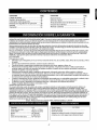
Content
Warranty Information ................................
Page
2
Content
Page
Off-Season Storage ................................... 23
Safe Operation Practices ..........................
3
Trouble-Shooting .......................................
23
Assembly .................................................
6
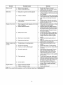
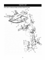
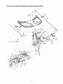
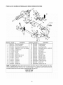
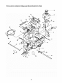
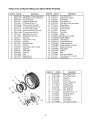
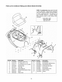
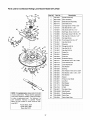
Parts List ...................................................
25
Operation .................................................
Maintenance .............................................
8
13
Slope Guide ..............................................
45
EspaSol .....................................................
47
16
Service Phone Numbers ............................ Back Cover
Service & Adjustment ...............................
LIMITED WARRANTY ON RIDING MOWER: For two (2) years from the date of purchase, if this Craftsman Riding Equipment is
maintained, lubricated and tuned up according to the instructions in the owner's manual, Sears will repair or replace free of
charge any parts that are found to be defective in material or workmanship according to the guidelines of coverage listed below.
Sears will also provide free labor for these applicable warranted parts for the two full years. During first 30 clays of purchase,
there will be no charges to service the product at your home for issues covered by this warranty. (See exclusions below).
For your convenience, IN HOME warranty service will still be available after the first 30 days of purchase, but a trip charge will
apply. This charge will be waived if the product is dropped off at an authorized Sears location. For the nearest authorized Sears
location, please call 1-800-4-MY-HOME®.
This warranty applies only while this product is within the United States.
EXCLUSIONS
This Warranty does not cover:
Expendable items which become worn during normal use, including but not limited to blades, spark plugs, air cleaners,
belts, and oil filters.
Standard Maintenance Servicing, oil changes or tune-ups
Tire replacement or repair caused by punctures from outside objects, such as nails, thorns, stumps, or glass.
Repairs necessary because of operator abuse, including but not limited to, damage caused by towing objects beyond the
capability of the riding equipment, impacting objects that bend the frame or crankshaft, or over-speeding the engine.
Repairs necessary because of operator negligence, including but not limited to, electrical and mechanical damage caused
by improper storage, failure to use the proper grade and amount of engine oil, failure to keep the deck clear of flammable
debris, or failure to maintain the equipment according to the instructions contained in the owner's manual.
Engine (fuel system) cleaning or repairs caused by fuel determined to be contaminated or oxidized (stale). In general, fuel
should be used within 30 days of its purchase date.
Normal deterioration and wear of the exterior finishes, or product label replacement.
Riding equipment used for commercial or rental purposes.
LIMITED WARRANTY ON BATTERY
For ninety (90) clays from date of purchase, if any battery included with this riding equipment proves defective in material or
workmanship and our testing determines the battery will not hold charge, Sears will replace the battery at no charge. During the
first 30 days of purchase, there will be no charges to replace the battery at your home. After the first 30 days, for your
convenience, IN-HOME warranty service will still be available but a trip charge will apply. This charge will be waived if the
Craftsman product is dropped of at an authorized Sears location. For the nearest authorized Sears location, please call 1-800-4MY-HOME®. This battery warranty applies only while this product is within the United States. This warranty gives you specific
legal rights, and you may also have other rights, which vary, from state to state.
Sears,
Horsepower: ...............................
Engine Oil ...................................
Fuel ............................................
Spark Plug: .................................
Engine: ........................................
Ignition Key (Std.) ........................
Roebuck
and Co.,Dept.817WA,
10.0
48 oz. or 1.4 liters
Unleaded Regular
P/N 491055
212907-0272
P/N 725-0201
Hoffman
Estates,
IL 60179
Model Number ........................... 247.27022
Serial Number ...........................................................
Date of Purchase ......................................................
Record both sedal number and date of purchase and keep
in a safe place for future reference.
Congratulations
onmaking
asmartpurchase.Your
new
Craftsman_
product
isdesigned
andmanufactured
foryears
ofdependable
operation.
Butlikeallproducts,
itmayrequire
repairfromtimetotime.That'swhenhaving
a Repair
Protection
Agreement
cansaveyoumoney
andaggravation.
Here's
what'sincluded
intheAgreement:
Expert service by our 12,000 professional repair
specialists
Unlimited service and no charge for parts and
labor on all covered repairs
Product replacement
be fixed
if your covered product can't
,t
Discount of 10% from regular price of service and
service-related parts not covered by the agreement;
also, 10% off regular price of preventive maintenance
check
4
Fast help by phone - phone support from a Sears
technician on products requiring in-home repair, plus
convenient repair scheduling
,i_
Purchase a Repair Protection Agreement now and protect
yourself from unexpected hassle and expense.
Once you purchase the Agreement, a simple phone call is all
that it takes for you to schedule service. You can call anytime
day or nighL or schedule a service appointment online. Sears
has over 12,000 professional repair specialists, who have
access to over 4.5 million quality parts and accessories.
That's the kind of professionalism you can count on to help
prolong the life of your new purchase for years to come.
Purchase your Repair Protection Agreement today!
Some limitations and exclusions apply. For prices and
additional information call 1-800-827-6655. Sears Installation
Service
For Sears professional installation of home appliances,
garage door openers, water heaters, and other major home
items, in the U.S.A. call 1-800-4-MY-HOME®
WARNING:
This and/or
symbol property
points out
safety
instructions
which,
notinstructions
followed, could
the personal safety
of important
yourself and
others.
Read and
followif all
in thisendanger
manual
before attempting to operate this machine. Failure to comply with these instructions may result in personal
injury. When you see this symbol--heed its warning.
WARNING:
The Battery and Engine Exhaust contains chemicals known to the State of California
to cause cancer, birth defects or other reproductive harm. The battery and posts contain lead;
wash hands after handling.
_lb
WARNING:
This machine was built to be operated according to the rules for safe operation in this
manual. As with any type of power equipment, carelessness or error on the part of the operator can result in
serious injury. This machine is capable of amputating hands and feet and throwing objects. Failure to
observe the following safety instructions could result in serious injury or death.
General Operation
1.
2.
3.
4.
5.
Read, understand, and follow all instructions on the
machine and in the manual(s) before attempting to
assemble and operate. Save this manual for future and
regular reference and for ordering replacement parts.
Be familiar with all controls and their proper operation.
Know how to stop machine and disengage them quickly.
Never allow children under 14 years old to operate this
machine. Children 14 years old and over should read and
understand operation instructions and safety rules in this
manual and should be trained and supervised by parent.
Never allow adults to operate this machine without
proper instruction.
To help avoid blade contact or a thrown object injury,
keep bystanders, helpers, children and pets at least 75
feet from the machine while it is in operation. Stop
machine if anyone enters the area.
6.
7.
8.
9.
Thoroughly inspect the area where the equipment is to
be used. Remove all stones, sticks, wire, bones, toys,
and other foreign objects which could be picked up and
thrown by the blade(s). Thrown objects can cause
serious personal injury.
Plan your mowing pattern to avoid discharge of material
toward roads, sidewalks, bystanders and the like. Also,
avoid discharging material against a wall or obstruction
which may cause discharged material to ricochet back
toward the operator.
Always wear safety glasses or safety goggles during
operation and while performing an adjustment or repair to
protect your eyes. Thrown objects which ricochet can
cause serious injury to the eyes.
Wear sturdy, rough-soled work shoes and close-fitting
slacks and shirts. Loose fitting clothes and jewelry can be
caught in movable parts. Never operate this machine in
bare feet or sandals.
10.Beaware
ofthemower
andattachment
discharge
direction
anddonotpointitatanyone.
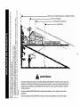
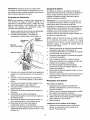
Donotoperate
the Slope Operation
Slopes are a major factor related to loss of control and tipmower
without
thedischarge
coverorentiregrass
over accidents which can result in severe injury or death. All
catcher
initsproper
place.
slopes require extra caution. If you cannot back up the slope
11.Donotputhands
orfeetnearrotating
partsorunder
the
or if you feel uneasy, do not mow it.
cutting
deck.Contact
withtheblade(s)
canamputate
For safety, use the slope guide on page 45 to measure
hands
andfeet.
12.Amissing
ordamaged
discharge
covercancause
blade slopes before operating this unit on a sloped or hilly area. If
the slope is greater than 15 degrees as shown on the slope
contact
orthrown
object
injuries.
gauge, do not operate this unit there.
13.Stoptheblade(s)
whencrossing
gravel
ddves,
walks,
or
roads
andwhilenotcutting
grass.
Do:
14.Watch
fortrafficwhenoperating
nearorcrossing
Mow up and down slopes, not across. Exercise extreme
roadways.
Thismachine
isnotforuseonpublic
roadway. 1. caution
when changing direction on slopes.
15.Donotoperate
themachine
whileundertheinfluence
of
2. Watch for holes, ruts, bumps, rocks, or other hidden
alcohol
ordrugs.
objects. Uneven terrain could overturn the machine. Tall
16.Mowonlyindaylight
orgoodartificial
light.Never
carry
grass can hide obstacles.
passengers.
3. Use slow speed. Choose a low enough speed setting so
17.Disengage
blade(s)
before
shifting
intoreverse.
Backup
that you will not have to stop or shift while on the slope.
slowly.
Always
lookdownandbehind
before
andwhile
Tires may lose traction on slopes even though the brakes
backing
toavoidaback-over
accident.
are functioning properly. Always keep machine in gear
18.Slowdownbefore
turning.
Operate
themachine
when going down slopes to take advantage of engine
smoothly.
Avoiderratic
operation
andexcessive
speed.
braking action.
19.Disengage
blade(s),
setparking
brake,
stopengine
and
4.
Follow the manufacturer's recommendations for wheel
waituntiltheblade(s)
cometoacomplete
stopbefore
weights or counterweights to improve stability of the
removing
grasscatcher,
emptying
grass,unclogging
machine. Use extra care with grass catchers or other
chute,removing
anygrassordebris,
ormaking
any
attachments. These can change stability of the machine.
adjustments.
5. Keep all movement on the slopes slow and gradual. Do
20. Never
leavearunning
machine
unattended.
Always
turn
not make sudden changes in speed or direction. Rapid
offblade(s),
placetransmission
inneutral,
setparking
engagement or braking could cause the front of the
brake,
stopengine
andremove
keybefore
dismounting.
machine to lift and rapidly flip over backwards which
21. Useextracarewhenloading
orunloading
themachine
could cause serious injury.
intoatrailerortruck.Thisunitshould
notbedrivenupor
6. Avoid starting or stopping on a slope. If tires lose traction,
downramp(s),
because
theunitcouldtipover,causing
disengage the blade(s) and proceed slowly straight down
serious
personal
injury.
Theunitmustbepushed
the slope.
manually
onramp(s)
toloadorunload
properly.
22. Muffler
andengine
become
hotandcancause
aburn.Do Do Not:
nottouch.
1. Do not turn on slopes unless necessary; then, turn slowly
and gradually downhill, if possible.
23. Check
overhead
clearances
carefully
before
driving
2. Do not mow near drop-off sites, ditches or embankments.
underlowtreebranches,
wires,
dooropenings
etc.,
The mower could suddenly turn over if a wheel is over the
where
theoperator
maybestruck
orpulled
fromtheunit,
edge of a cliff, ditch, or if an edge caves in.
which
couldresultinserious
injury.
24. Disengage
allattachment
clutches,
depress
thebrake
3. Do not try to stabilize the machine by putting your foot on
the ground.
pedalcompletely
andshiftintoneutral
before
attempting
tostartengine.
4.
Do not use a grass catcher on steep slopes.
25. Yourmachine
isdesigned
tocutnormal
residential
grass 5. Do not mow on wet grass. Reduced traction could cause
sliding.
ofaheightnomorethan10".Donotattempt
tomow
through
unusually
tall,drygrass(e.g.,pasture)
orpilesof 6. Do not shift to neutral and coast downhill. Over-speeding
may cause the operator to lose control of the machine
dryleaves.
Drygrassorleaves
maycontact
theengine
resulting in serious injury or death.
exhaust
and/or
builduponthemower
deckpresenting
a
potential
firehazard.
Children
26. Useonlyaccessories
andattachments
approved
forthis
machine
bythemachine
manufacturer.
Read,
Tragic accidents can occur if the operator is not alert to
understand
andfollowallinstructions
provided
withthe
the presence of children. Children are often attracted to
accessory
orattachment.
the machine and the mowing activity. They do not
27. Dataindicates
thatoperators,
age60yearsandabove,
understand the dangers. Never assume that children will
areinvolved
inalargepercentage
oftractor-related
remain where you last saw them.
injuries.
These
operators
should
evaluate
theirabilityto
a. Keep children out of the mowing area and in
operate
thetractor
safelyenough
toprotect
themselves
watchful care of a responsible adult other than the
andothers
fromserious
injury.
operator.
b. Be alert and turn machine off if a child enters the
28. Ifsituations
occurwhicharenotcovered
inthismanual,
usecareandgoodjudgment.
Contact
Sears
service
area.
center
forassistance.
c. Before and while backing, look behind and down
1,
for small children.
d.
e.
f.
2.
Never carry children, even with the blade(s) shut
off. They may fall off and be sedously injured or
interfere with safe machine operation.
Use extreme carewhen approaching blind
corners, doorways, shrubs, trees or other objects
that may block your vision of a child who may run
into the machine.
Disengage the cutting blade(s) before shifting in
reverse. The "No-Cut-In Reverse" feature
emphasizes not to cut in reverse and to avoid
back-over accidents; do not defeat it.
g. Keep children away from hot or running engines.
They can suffer burns from a hot muffler.
h. Remove key when machine is unattended to
prevent unauthorized operation.
Never allow children under 14 years old to operate the
machine. Children 14 years old and over should read and
understand the operation instructions and safety rules in
this manual and should be trained and supervised by a
parent.
m.
General Service
1.
2.
3.
4.
5.
Safe Handling Of Gasoline
1.
To avoid personal injury or property damage use extreme
care in handling gasoline. Gasoline is extremely
flammable and the vapors are explosive. Serious
personal injury can occur when gasoline is spilled on
yourself or your clothes which can ignite. Wash your skin
and change clothes immediately.
a. Use only an approved gasoline container.
b. Never fill containers inside a vehicle or on a truck
or trailer bed with a plastic liner. Always place
containers away from your vehicle before filling.
c. When practical, remove gas-powered equipment
from the truck or trailer and refuel it on the ground.
If this is not possible, then refuel such equipment
on a trailer with a portable container, rather than
from a gasoline dispenser nozzle.
d. Keep the nozzle in contact with the rim of the fuel
tank or container opening at all times until fueling
is complete. Do not use a nozzle lock-open
device.
e. Extinguish all cigarettes, cigars, pipes and other
sources of ignition.
f.
Neverfuelmachineindoors.
g. Never remove gas cap or add fuel while the
engine is hot or running. Allow engine to cool at
least two minutes before refueling.
h. Never over fill fuel tank. Fill tank to no more than
Y_inch below bottom of filler neck to allow space
for fuel expansion.
i.
Replace gasoline cap and tighten securely.
j.
If gasoline is spilled, wipe it off the engine and
equipment. Move unit to another area. Wait 5
minutes before starting the engine.
k. To reduce fire hazards, keep machine free of
grass, leaves, or other debris build-up. Clean up
oil or fuel spillage and remove any fuel soaked
debris.
L
Never store the machine or fuel container inside
where there is an open flame, spark or pilot light
as on a water heater, space heater, furnace,
clothes dryer or other gas appliances.
Allow a machine to cool at least 5 minutes before
storing.
6.
7.
8.
9.
10.
11.
12.
13.
14.
Never run an engine indoors or in a poorly ventilated
area. Engine exhaust contains carbon monoxide, an
odorless, and deadly gas.
Before cleaning, repairing, or inspecting, make certain
the blade(s) and all moving parts have stopped.
Disconnect the spark plug wire and ground against the
engine to prevent unintended starting.
Periodically check to make sure the blades come to
complete stop within approximately (5) five seconds after
operating the blade disengagement control. If the blades
do not stop within the this time frame, your unit should be
serviced professionally by an authorized dealer.
Check brake operation frequently as it is subjected to
wear during normal operation. Adjust/service as required.
Check the blade(s) and engine mounting bolts at
frequent intervals for proper tightness. Also, visually
inspect blade(s) for damage (e.g., excessive wear, bent,
cracked).
Replace the blade(s) with the original equipment
manufacturer's (O.E.M.) blade(s) only, listed in this
manual. "Use of parts which do not meet the original
equipment specifications may lead to improper
performance and compromise safety!"
Mower blades are sharp. Wrap the blade or wear gloves,
and use extra caution when servicing them.
Keep all nuts, bolts, and screws tight to be sure the
equipment is in safe working condition.
Never tamper with the safety interlock system or other
safety devices. Check their proper operation regularly.
After striking a foreign object, stop the engine, disconnect
the spark plug wire(s) and ground against the engine.
Thoroughly inspect the machine for any damage. Repair
the damage before starting and operating.
Never attempt to make adjustments or repairs to the
machine while the engine is running.
Grass catcher components and the discharge cover are
subject to wear and damage which could expose moving
parts or allow objects to be thrown. For safety protection,
frequently check components and replace immediately
with original equipment manufacturer's (O.E.M.) parts
only, listed in this manual. "Use of parts which do not
meet the original equipment specifications may lead to
improper performance and compromise safety!"
Do not change the engine governor settings or overspeed the engine. The governor controls the maximum
safe operating speed of the engine.
Maintain or replace safety and instruction labels, as
necessary.
Observe proper disposal laws and regulations for gas,
oil, etc. to protect the environment.
Your Responsibility
Restrict the use of this power machine to persons who
read, understand and follow the warnings and instructions
in this manual and on the machine.
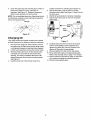
Unpacking
1.
2.
3.
4.
5.
6.
Vent
Remove all screws and staples from the crate.
Holding sides of the crate firmly, lift top of the crate
up and set it aside. Avoid tire punctures.
Remove and discard plastic bag covering the unit.
Lift the rear of the mower past the bottom of the
crate. Repeat for the front.
Be sure the parking brake is disengaged. See
Figure 4 for location of the parking brake.
Roll unit out of the crate.
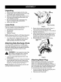
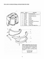
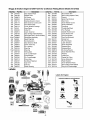
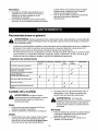
Loose Parts
Assembly
Figure 1
Remove loose parts from the grass catcher and/or the
crate very carefully. Compare with list below.
3.
•
•
Mulching plug & side-discharge
Oil drain hose
4.
•
•
Ignition keys
Operator's manual
chute
5.
NOTE: Reference to RIGHT or LEFT side of the tractor
in this manual is observed from operator's position.
•
Your riding mower is shipped with motor oil in the
engine. However, you must check the oil level
before operating. Be careful not to overfill.
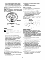
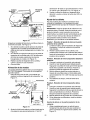
Attaching Side-Discharge
6.
Remove the two wing nuts (A and B in Figure 2 )
from two ends of the grasscatcher chute.
Loosen the wing nut (C in Figure 2 ) in the middle of
the chute. Do not remove.
Slide the grasscatcher chute to the right and out of
the deck frame. Slide the side-discharge chute in
and place it on the deck so that the three wing nut
positions align with those on the deck.
Reinsert wing nuts A and B. Tighten all three.
GrassCatcher
Chute
Chute
Win
Nut_l
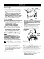
Your riding mower is shipped to you with the grass
catcher fully assembled on the unit. A side-discharge
chute and a mulching plug are included as loose parts.
Follow the instructionsbelow to attach the sidedischarge chute.
j_
WARNING:
Do not operate the mower if the
grass catcher, discharge chute or mulching
plug is not firmly installed on the mower.
1.
2.
Lower the cutting height adjustment lever to the
lowest position.
To access the grass catcher, lift the hood assembly
from the left side of the hood only. Stand on the
right side of the unit and pivot the hood assembly
towards you until fully opened. See Figure 1.
NOTE: Do not lift the hood assembly by the two vent
openings located behind the seat.
Nut
Figure
2
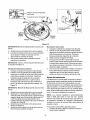
Attaching Mulch Plug
While operating your riding mower, you have three
options: (i) to collect grass clippings in the grass
catcher, (ii) to discharge grass clippings on the side, or
(iii) to mulch grass and recirculate clippings back to the
lawn. For the third option, attach the mulching plug to
the side-discharge chute and then to the deck.
1.
2.
Put two hex bolts through the mulching plug at the
respective openings. See Figure 3.
Place nuts over the hex bolts.
3.
Wing Nut
Side Discharge Chute
4.
5.
A
ulchin
Plug
Figure 3
6.
Insert the plug into the side-discharge chute
aligning the two slots on two sides of the sidedischarge chute with those on the mulching plug.
To attach the mulching plug now to the unit, follow
earlier instructions to attach side-discharge chute
to the deck.
Place wing nut on each of the hex bolts and thread
a few turns. See Figure 3. Check that the mulch
plug is aligned correctly within the discharge chute.
Tighten both wing nuts.
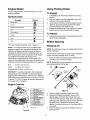
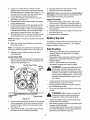
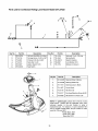
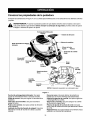
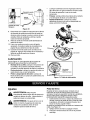
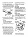
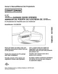
Know Your Riding Mower
Compare the illustrations in Figure 4 with your riding mower to familiarize yourself with the location of various
controls and adjustments.
,_
WARNING:
The operation of any riding mower can result in foreign objects being thrown into the
operator's eyes, causing severe eye damage. Always wear safety glasses before operating the mower, or
while performing any adjustments or repairs on it.
Throttle/Choke
Control
Steering Wheel
Shift Lever
Indicator
g Height
Adjustment Lever
Blade Engagement
Pedal
Ignition
Switch
Side Discharge
Chute
Pedal
Cutting
Deck
Brake
Pedal
Parking
Blade
Pedal
Lock
NOTE: Gas tank is not shown here
Figure 4
Throttle/Choke Control: Use to regulate the engine
speed and to start the engine.
"Go" Pedal: Use to regulate the ground speed of the
riding mower.
of grass clipping in the bag and when to empty it.
Parking Brake: Use to stop the mower from moving
while parked.
Ignition Switch: Use to turn the engine ON or OFF.
Blade Engagement Pedal: Use to engage or
disengage the blade.
Shift Lever: Use to change direction of the mower.
Blade Lock: Use to lock blade at the engaged position.
Grass Fill Level Indicator:
Cutting Height Adjustment Lever: Use to raise and
Use to determine the level
lowercuttingdeckwhichdetermines
thecuttingheight.
BrakePedal:Usetostopthemower'sforwardor
reversemotion.
2.
For Your Safety
•
•
•
Know location and function of all controls.
Be sure blades and engine are stopped before
placing hands or feet near blades.
Before leaving operator's position, disengage
blade(s), place the shift lever in neutral, engage
parking brake, shut engine off and remove key.
NOTE: Look to the rear and
make sure the path is free of
obstacles before positioning the
shift/ever to the reverse.
3.
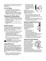
Stopping the Riding Mower
1.
2.
3.
4.
5.
Release blade engagement pedal all the way.
Release "Go" Pedal and depress the brake pedal.
When the mower comes to a complete stop, place
the shift lever in neutral.
Engage the parking brake by pulling up on the
parking brake knob.
Turn the ignition key to OFF position and remove
the key.
Safety Interlock
This unit is equipped with a safety interlock system for
your protection. The interlock safety switches are
connected to the brake pedal, the blade engagement
pedal, the shift lever, and the seat.
4.
•
•
,_
To prevent the engine from starting unless the
brake pedal is depressed and the blade
engagement pedal is disengaged;
To shut off the engine if the blade pedal is not
disengaged when the shift lever is put into reverse;
and
To shut the engine off when the operator leaves the
seat without engaging the parking brake.
WARNING:
TO avoid
risk mower
of serious
injury, do not operate
thethe
riding
if the
interlock system is malfunctioning.
Using Shift Lever
This lever is used to regulate direction of the riding
mower. It can be set at forward, neutral, or reverse
settings. These settings are marked F, N, and R
respectively on the unit. This unit is designed not to
mow when the shift lever is in B position. (If the
blade is engaged while shift lever is at the R position,
the unit wilt shut off. To restart the unit, disengage the
blade.)
1.
Before you move the shift lever to any of the
positions, depress the brake pedal and stop the
unit. Keep your foot on the brake pedal.
Do not force the shift lever. If it does not shift,
release the brake pedal slightly to line up the
shifting collar in the transmission, then try to move
the shift lever.
Slowly release the brake pedal and take your foot
off the pedal. Always make sure that there is no one
in the way when you run the mower.
Using Throttle/Choke
Control
used to increase or decrease
the speed of the engine.The
FAST and the SLOW positions
are marked with illustrations of
a rabbit and a turtle
respectively.
The
throttle/choke control is
•
The purpose of the safety interlock system is threefold:
•
The shift lever is locked at
the N position. Move the
lever outwards (left) and
slide the lever upward to F
or downward to R position
as desired.
•
•
I___
For normal operation and
when using a grass
catcher, move the throttle/
choke control to the FAST position.
For maximum charging of the battery and also for a
cooler engine while running, move the throttle/
choke control to the FAST position.
For transport and to tow pull-behind attachments,
move the throttle/choke control to the SLOW.
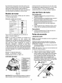
Grass Fill Level Indicator
This indicator was designed
to add convenience to your
riding mower. While the
mower is running, air will flow
through the discharge chute
and into the grass catcher. If
the grass catcher is empty,
air flows through easily
Grass Fill Level
pushing the ball up. If the
Indicator
grass catcher is full, air does
not flow through it allowing the ball to fall. So if you see
the ball in the grass catcher fill level indicator falling
down, you should stop the mower and empty the bag.
Engine Model
Using Parking Brake
This is a single cylinder, air-cooled engine. It is a low
emissions engine.
To engage
1.
Symbols Used
Message
2.
Symbol
Safety alert
_,
3.
On off
Read owner's manual
4.
Oil
Fuel shut-off
]_
Choke
I",l
Fuel
._
Stop
I_1
Completely push the brake pedal down and stop
the unit.
With your right foot on the brake pedal, move the
shift lever to the neutral position.
Continuing to hold down the brake pedal with your
right foot, pull up the parking brake knob. Make
sure the parking brake holds the unit.
Release the brake pedal. Stop engine and remove
ignition key. Now your riding mower is parked.
To release
5.
Depress the brake pedal. The parking brake will be
automatically disengaged.
Before Starting
For hazard symbol meanings, refer to page 44.
Filling Up Oil
NOTE: In the state of California, the 210000 series
engines covered in this manual are certified by the
California Air Resources Board to meet emissions
standards for250 hours. Such certification does not
NOTE: The riding lawn mower is shipped with oil in the
engine crankcase.
grant the purchaser, owner or operator of this engine
any additional warranties with respect to the
performance or operational life of this engine. This
engine is warranted solely according to the product and
emissions warranties stated elsewhere in this manual
1.
Bore
3-7/16 in. (87.31 mm)
Stroke
2-17/64 in. (77.78 mm)
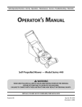
Check oil level in the engine oil sump before starting the
engine. (Oil sump capacity: 48 oz./1.4 liter)
Place the mower on level ground and flip the hood
assembly up to access the engine.
NOTE: Do not lift the hood assembly by the two vent
openings located behind the seat.
A
Dipstick
Displacement 21.00 cu. in. (344.1 cc)
Read oil
Fill up if
needed
IMPORTANT: For practical operation, the horsepower
loading should not exceed 85% of rated horsepower.
Engine power will decrease 3-1/2% for each 1,000 feet
(300 meters) above sea level and 1% for each 10 F (5.6
C) above 77 F (25 C). Engine will operate satisfactorily
at an angle up to 15 degrees.
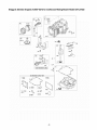
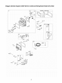
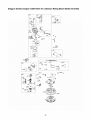
Engine Controls
_2
1.
2.
3.
4.
5.
6.
7.
8.
9.
10.
Oil drain*
Figure 6
Oil fill/Dipstick
Rotating Screen
Blower Housing
Muffler*
Electric Starter*
Air Cleaner
Fuel Filter
Carburetor
Spark plug wire
* Not shown
Figure 5
10
2.
3.
Remove dipstick and wipe it clean with cloth.
Replace and tighten the dipstick. Remove the
dipstick again and check the oil level mark on it.
The oil level should be at FULL line on the dipstick.
See Figure 6A. If the level is short of that, add oil to
the oil fill slowly. Recheck the oil level on the
dipstick. If needed, add more oil. See Figure 6B. Do
not overfill.
4.
Place the dipstick in position and tighten to secure.
See Figure 6C.
Type of Oil
Type of Gasoline
1.
2.
•
Refer to the chart below for proper grade of oil.
Use a high quality detergent oil classified "For
service SF, SG,SH, SJ" or higher.
3. Do not use special additives.
Synthetic oil meeting ILSAC GF-2, API certification and
API service symbol with "SJ/CF Energy Conserving" or
higher is an acceptable oil at all temperatures. Use of
synthetic oil does not alter required oil change intervals.
•
•
NOTE: Some fuels, called oxygenated or reformulated
gasoline, are blended with alcohol or ether. Using these
blends frequently can damage the fuel system or affect
performance. If engine performance is affected, use
gasoline with Iower percentage of alcohol or ether.
SAE Viscosity Grades
30
_5W-30,
Use clean, fresh, regular unleaded gasoline with
minimum 85 octane rating.
Do not use gasoline mixed with methanol, or
gasoline which has been stored for more than 30
days. Always purchase fuel in quantity that can be
used up within 30 days. Fresh fuel prevents gum
from forming in the fuel system or on carburetor.
Do not mix gasoline with engine oil.
L
10W-30
Starting Engine
°F -20°'
0°'
20°'
40°'
60°'
80°'
100°'
1.
2.
3.
Starting temperature range anticipated before next oil change
* CAUTION: Air cooled engines run hotter than automotive
engines. The use of non-synthetic multi-viscosity oils (5W30, 10W-30 etc.) in temperatures above 40°F will result in
higher than normal oil consumption. When using a multiviscosity oil, check oil level more frequently.
4.
5.
** CAUTION: SAE 30 oil, if used below 40°F, will result in
hard starting and possible engine bore damage due to
inadequate lubrication.
6.
NOTE: If engine floods, set choke to OPEN/RUN
position, place throttle in FAST and crank until engine
starts.
Battery
Ordinarily the battery is charged and ready for use; so
you will not have to charge it before starting. However,
if the battery is put into service for the first time after the
date shown on the side of the battery, you will have to
charge it for a minimum of one hour at 4-6 amps. Refer
to Service & Adjustments section of this manual for
instructions on charging the battery.
Operating
1.
2.
The battery is located under the hood assembly above
the left rear wheel. Refer to Figure 20.
3.
4.
5.
Filling Up Gasoline
6.
,_
WARNING:
fuel from
tank sparks,
outdoorsopen
or in wellventilated area, Fill
away
flames, pilot lights, heat and other ignition
SOUrCeS.
,_
NOTE: On a riding mower which has already been
started and/or operated once immediately prior to this
gasoline fill-up, turn engine off and let cool at least two
minutes before removing gas cap.
1.
2.
Be sure the wire is attached to the spark plug.
Depress the brake pedal with your right foot.
Set throttle/choke control in the CHOKE position
(all the way forward).
Place the shift lever in the NEUTRAL position.
Turn ignition key to the START position. Once the
engine starts, let key return to ON position.
Move throttle/choke control out of CHOKE position
and into FAST throttle position.
the Riding Mower
Depress the brake pedal so that the parking brake
is disengaged.
Place the shift lever in either the FORWARD or the
REVERSE position as you desire. Look to the rear
and check before backing up.
Release the brake pedal.
Depress the "Go" Pedal.
To stop, release the "Go" Pedal and depress the
brake pedal.
Press the blade engagement pedal downward until
the blades are turning.The blades can be engaged
either while the mower is moving or standing.
WARNING:
When the blades are engaged,
keep hands and feet away from the discharge
opening, the blades or any part of the deck.
_
WARNING:
Do not tip the equipment at an
angle which causes the gasoline to spill.
Remove gas tank cap and fill tank to approximately
1.5 inches below top of neck to allow for fuel
expansion. Be careful not to overfill.
Replace cap on the gas tank and tighten to secure.
NOTE: Your riding mower is equipped with a blade lock
to keep the blade engaged without the operator having
to depress the blade pedal continuously. See Figure 4.
NOTE: If fuel spills on part of engine or vehicle, wait
until it evaporates before starting engine.
7.
11
To engage the blade lock: While pressing down
on the blade pedal, push the blade lock down with
your heel. It should click into the "blade engaged"
position. To disengage the blade lock, simply push
down on the blade pedal and release the lock.
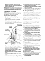
Using the Riding Mower
Observe safety rules listed on pages 3-5 of this manual
for safe operation of your riding mower. The
recommended mowing pattern is given below:
Stopping the Riding Mower
See page 9 for detailed instruction.
NOTE: Do not leave the key in the ON position when
you are not operating the mower. Such action will drain
the battery dead.
tTc.
NOTE: Do not choke carburetor to stop engine.
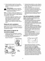
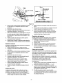
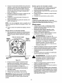
To Empty Grass Catcher
1.
2.
3.
4.
5.
•
Stop the mower completely, pult up on the parking
brake knob and take the ignition key out. Get off the
operator's seat.
Pivot the hood assembly up. Pull up the
grasscatcher bag by the handle and take it to the
proper disposal site. See Figure 7.
Hold the bag away from your body. Push down on
the bag lever and let the bottom section of the bag
fall downwards. Grass clippings witl be disposed off
from the bottom. See Figure 7.
Tap the bag on the ground so that the three legs of
the bag press against the ground. The bag lever
should snap close while you push the bag
downwards.
Replace the bag on to the mower making sure the
bag is placed on the flange on top of the discharge
chute. Pivot the hood assembly down.
•
•
•
•
•
•
BakHandle
•
Grass Catcher
Bag
.'JJ
Before mowing, make sure that the cutting deck is
leveled. For deck adjustment, refer to page 17.
You can engage the blade by pressing on the blade
engagement pedal with your left foot while sitting at
the operator's position.
When mowing an area for the first time, watch out
for objects lying on the grass. If you strike a foreign
object, stop the engine. Remove wire from spark
plug and thoroughly inspect the riding mower for
any damage. Repair the damage before operating
it again.
Avoid scalping the lawn by adjusting the cutting
height upwards and/or sharpening the blades.
Mow at full throttle. Learn the terrain on which you
are mowing. For best mowing results, mow only
when the grass is dry.
Mow grass often and in regular intervals so that you
can cut only 1/3 of the grass blade in one mowing.
To empty grass bag, stop the riding mower
completely, engage the parking brake, and turn
the ignition off. This will prevent the hot engine
exhaust gas from browning the grass.
Many communities no longer haul grass clippings
to landfills. Composting the clippings from your
grass catcher is a viable solution. For this you witl
have to empty the grass catcher at the designated
composting site.
Mulching
•
Assembly
•
•
Figure 7
12
Your riding mower is equipped with a mulching plug
to mulch the grass and recycle into the lawn instead
of collecting in the grasscatcher bag.
Mulch only when the grass is dry. Mulching wet
grass may damage the underside of the deck
because wet grass tends to stick to it. Clean deck
thoroughly if you mulch wet grass.
For effective mulching, overlap mowing paths so
that the clippings are distributed evenly.
General Recommendations
_lb
WARNING:
Always stop engine and disconnect spark plug wire before any maintenance or adjustments.
Always maintain safety and follow instructions given below closely for smooth completion of job.
The warranty on this riding mower does not cover items that have been subjected to operator abuse or
negligence. To receive full value from the warranty, operator must maintain the riding mower as instructed in
this manual. Refer to the Maintenance Schedule below.
We do not recommend the use of pressure washers or garden hose to clean your unit. These may cause
damage to electrical components, spindles, pulleys, bearings or the engine. The use of water may shorten life
of your riding mower and reduce its serviceability
To ensure safe operation, all nuts and bolts must be checked periodically for correct tightness.
Maintenance
Schedule
First 5 hrs.
25 hours
Check blade, sharpen or replace if needed
50 hours
100 hrs.
Season
Reassembly
_
Lube pivot points, steering shaft, gear
Lube deck linkage, front wheels
Change engine oil
_
Service air cleaner in engine
Service spark plug
,_
Clean cooling system of the engine
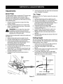
Blade Care
_
WARNING:
Reassembly
Protect your hands by wearing
heavy gloves or using a rag to grasp the cutting
blade. Avoid personal injury.
Removal
1.
2.
Remove the 5/8" hex flange nut which holds the
blade to the blade spindle.
Remove blade from the spindle. See Figure 8.
Spindle
I
Sharpening
1.
2.
i_
_Blade
When sharpening the blade, follow original angle of
grind as a guide. It is extremely important to grind
each cutting edge equally to prevent an
unbalanced blade.
Figure 8
1.
Test the blade by balancing it on a round shaft
screwdriver. Remove metal from the heavy side
until it balances evenly.
WARNING:
3.
Before reassembling
the spindle with light
Align "star" fitting on
the spindle.
Install the blade with
4.
"Bottom" (or with part number) facing the ground
when the riding mower is in the operating position.
Tighten the flange nut securely. See Figure 8.
2.
Unbalanced blade may cause
excessive vibration at high speeds, may damage
the riding mower and/or cause personal injury.
the blade to the unit, lubricate
oil (or engine oil).
new blade with the "star" on
the side of the blade marked
Blade Mounting Torque: 70/90 ft.-tbs, maximum.
13
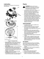
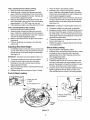
Lubrication
Engine
See Figure 9 for an illustration of the lube points
described below.
any
_1=
Lube
WARNING:
performing
maintenance onBefore
the engine,
disconnect the
spark plug wire and the battery to prevent
unintentional starting or sparking.
•
•
Lube
ube
•
Change engine oil after first five to eight hours of
use, then every 50 hours or every season,
whichever comes earlier. Change oil every 25
hours when operating the riding mower under
heavy load or in high temperatures.
Poor engine performance and flooding usually
indicate that air cleaner should be serviced. Service
pre-cleaner and the cartridge every 25 hours of use
or once every season, whichever comes earlier.
Clean more frequently under dusty conditions. Also
replace air cleaner parts if these are very dirty.
The spark plug should be cleaned and the gap
reset every 100 hours of use or once a season,
whichever comes earlier.
Cleaning Engine
1.
Promptly wipe off any fuel or oil spilled on the
machine with clean cloth.
2.
Clean the underside of the blade housing after
each mowing. Do not let clippings or debris
accumulate around the blade which may cause rust
on the deck.
3.
Using a brush or cloth, remove grass, chaff or
debris from the finger guard on the engine daily to
prevent overheating of the engine. Do not clean
with a forceful spray of water since water
contaminates the fuel system.
Keep the throttle linkage, springs and controls free
of debris.
If engine muffler is equipped with spark arrester
screen, remove and clean the screen regularly.
Replace if damaged or plugged with debris.Clean
muffler area and remove any grass or other debris
before operating the unit.
4.
_ube
5.
before
semby)
Viewed from the bottom
Figure 9: Lubrication Chart
•
•
•
•
•
•
Air Cleaner
Blade Assembly: Lubricate blade assembly and
deck spindle only while reassembling the blade
either after sharpening or replacement.
Pivot Points: Lubricate pivot points with light oil
once a season.
Steering Shaft and Gear: Lubricate steering shaft
and spline at least once a season with light oil.
Lubricate teeth of the external steering gears with
automotive multi-purpose grease every 25 hours of
operation or once a season.
Linkage: Lubricate all deck linkage and height
adjustment linkage with a light oil.
Front Wheels: Lubricate front wheels at least once
Service the air cleaner every 25 hours of operation.
Service more frequently if operating under extremely
dusty conditions. Locate air cleaner on engine.
1.
Remove clamp and pull air cleaner from intake
manifold.
2.
3.
Replace with air cleaner (Sears part # 698-973).
Reassemble the air cleaner.
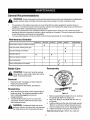
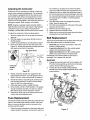
Spark Plug
1.
2.
3.
a season with automotive multi-purpose grease.
14
Clean area around the spark plug base.
Remove and inspect the spark plug.
Replace the spark plug if electrodes are pitted,
burned, or the porcelain is cracked. See Figure 10.
4.
Clean the spark plug and reset the gap to 0.020" at
least once a season or every 100 hours of
operation. See Figure 10. Replace if necessary.
Refer to parts list section for part number.
5.
6.
7.
NOTE: Do not sandblast spark plug. Spark plug should
be cleaned by scraping or wire brushing and washing
with a commercial solvent.
_
.020, gap
suitable container for collecting spent engine oil.
Grip oil drain valve, push in and turn counterclockwise until it stops. See Figure 11 inset. Pull out
the drain valve.
Wait till oil has drained into container completely.
Grip oil drain valve, push in, then turn clockwise
until it stops.
_
•
Oil Drain
Valve
Valve
\
Cover -_
Figure 10
Oil Drain-_'J[f
Hose
_,_
Changing Oil
Your riding mower has a plastic oil drain hose, packed
with the loose parts, for draining oil from the crankcase.
1.
2.
3.
4.
\"
......
L
Figure 11
8.
Carefully disconnect the hose from the oil drain
valve to avoid spillage on the equipment and
replace the yellow cap. Remove container and
dispose off the spent oil appropriately.
9. Remove dipstick from the oil fill on the engine.
10. Fill up with fresh engine oil of appropriate grade.
Refer to the viscosity chart on page 11 for oil type.
11. Check oil level as instructed on page 10. Add more
oil if needed and tighten the dipstick securely.
12. Flip the hood assembly back.
Run the mower engine for a few minutes, and turn
the ignition key off. Make sure that the riding mower
is completely stopped and parking brake engaged.
Lift the hood assembly to access the oil drain valve.
Remove yellow valve cover on the oil drain valve
and attach one end of the oil drain hose to this
opening. This valve is located at the end of a 90
degree fitting near the fuel tank mounting bracket.
See Figure 11.
Lead the other end of the oil drain hose into a
15
8.
Adjustments
Brake Pedal
"Go"
The brake pedal needs to contact the PTO (power take
off) switch for the engine to start. During normal
operation of the riding mower, the brake is subject to
wear and tear. Periodically check the brake by carrying
out the following test:
1.
Release the parking brake and place the riding
mower in neutral.
2.
Depress the brake pedal and try to roll the riding
mower. The tractor should not move. If the tractor
moves, adjust the brake.
1.
2.
3.
4.
5.
Do not adjust
theARNING:
engine is running.
Be surethe
to brake
block while
the
wheels of the riding mower before making any
adjustments on the brake cable.
7.
8.
Adjustment to the brake pedal is made at the cable end.
See Figure 12.
1.
2.
3.
4.
5.
6.
7.
Pedal
Adjustment to the "Go" Pedal is made at the cable end.
See Figure 12.
6.
_ill
Unlock parking brake and repeat the test described
above. Readjust if necessary.
Set the parking brake and turn ignition key off.
Shift the cutting height lever to the lowest position.
Pivot the hood assembly up and remove the
grasscatcher bag and the side-discharge chute or
the mulching plug from the riding mower.
Disconnect wire from the spark plug.
Locate the speed control cable under the front
housing. See Figure 12.
Loosen the jam nuts and back the cable out to
tighten or thread inward to loosen as shown.
Retighten the jam nuts when proper tension is
reached.
Reconnect the spark plug wire and pivot the hood
assembly down.
Cutting Height
Set the parking brake and turn ignition key off.
Shift the cutting height lever to the lowest position.
Pivot the hood assembly up and remove the
grasscatcher bag and the side-discharge chute or
the mulching plug from the riding mower.
Disconnect wire from the spark plug.
Locate the brake cable on the right side under the
front housing. See Figure 12.
Using a pair of 1/2' wrenches, loosen the jam nuts
and back the cable out to tighten or thread inward
to loosen. See Figure 12 inset.
Retighten the jam nuts when proper tension is
reached.
The deck cutting height adjustment lever is located on
the hood assembly. For a representation of the cutting
height positions, refer to Figure 4.
1.
2.
3.
4.
Pull the lever out of the slot and slide it upward or
downward to the desired cutting height.
Lower the cutting height to mow close to the
ground.
Raise the deck height to the highest position when
you ride on a sidewalk or a road.
To mow tall or thick grass, first cut with height
adjustment lever at the highest position, then cut
again with the lever at a lower position.
Brake
Cable
;ontrol
asher
Cable*
1
_Tighten
Loosen
*Same type of adjustment on both cables
(only one shown here)
Figure 12
16
Seat Position
2.
The seat position on the riding mower can be adjusted
to maximize the operator's convenience.
1.
2.
3.
4.
3.
Stop the mower completely and engage the parking
brake. Turn ignition off.
Pivot the hood assembly up.
Loosen the four self-tapping screws on the bottom
of the seat.
Slide the seat forward or backward in the slot, and
position it as desired. Retighten the four screws.
Blade Engagement
4.
Wheel Alignment
The front wheels should toe-in 1/t 6-5/16 inch. To adjust
toe-in, follow these steps:
1.
Pedal
The blade engagement pedal should be adjusted so
that if you depress it about 3/4" from the front of the
blade brake slot, it will contact the PTO switch and
cause it to engage the deck belt.
2.
Under normal operation, the blade engagement pedal
should not require frequent adjustment. However,
perform the following test periodically and make sure
that it is in fine working condition.
1.
2.
3.
3.
Steerin_
Segment
NOTE: The deck engagement cable will be correctly
adjusted when the cable moves approximately 1/2" off
center line in both directions.
_/\
\\\
Remove the 3/8" hex nut and lock washer which
hold the ball joint to the steering segment. See
Figure 14.
Adjust the ball joint in or out until the wheels toe-in
approximately t/16-5/16" (Dimension "B" should
be approximately 1/16-5/16" less than dimension
"A'). See Figure 14.
Replace the ball joint into the steering segment,
and replace the 3/8" hex nut and the lock washer.
Hex Nut
Pivot the hood assembly up and check if there is
enough slack on the deck engagement cable.
Depress the blade engagement pedal (about 3/4
inch) and check if the belt is engaging.
If the cable is tight or too loose or the belt is not
engaging, adjust the deck engagement cable.
Deck
Engagement
If the belt is engaging sooner than when the blade
engagement pedal is 3/4" from the PTO switch,
tighten both hex nuts on the cable. See Figure 13.
Repeat the blade engagement test and readjust if
necessary.
Pivot the hood assembly back.
Washer
Rod
Ball
Joint
Hex
Nut
1/16-5/16"
lessthan A
Figure 14
Adjusting the Deck
There are three tests for checking deck leveling on the
riding mower. The results of each test will determine
what kind of leveling, if at all, the equipment needs.
IMPORTANT: Perform adjustments to the deck on a flat,
level surface. Before continuing with deck adjustment,
check air pressure in all four tires. Recommended air
pressure is 12 psL Please note that the valve stems on
this riding mower are on the inside of the front wheels
and on the outside of the rear wheels.
Test 1: Checking Rear Deck Height Adjustment
1. Lift the hood assembly and remove grass catcher
from the riding mower. Place the deck in the
highest position.
2. Inspect rear of deck. If the deck is contacting the
cable bracket in front of the transmission, you will
have to adjust the rear deck height.
Figure 13
Adjustment to the blade brake will have to be made at
the cable end. See Figure 13.
1.
If the belt is slipping when you depress the blade
engagement pedal about 3/4 ", loosen the two hex
nuts on the cable. See Figure 13.
17
Test 2: Checking Front to Rear Leveling
1. Place the deck in the highest position.
2. Wearing a pair of heavy work gloves to prevent
injury, rotate the cutting blade so that it is pointed
front to back and parallel to the rider. Depress and
lock the deck engagement pedal.
3. Measure the distance from the front and the rear
tips of the blade to the ground.The front should be
approximately 1/4_ to 3/8" lower than the rear.
4. If the distance is higher, level the deck front to rear.
1.
2.
3.
IMPORTANT: Do not try to loosen/tighten
Test 3: Checking Side to Side Leveling
1. Place the deck in the highest position.
2. Wearing a pair of heavy work gloves to prevent
injury, rotate the cutting blade so that it is pointed
side to side and perpendicular to the rider. Depress
and lock the deck engagement pedal.
3. Measure the distance from the tips of the blade to
the ground.
4. If the two distances are unequal, level the deck
side to side.
Adjusting
1.
2.
3.
4.
5.
4.
5.
6.
7.
Rear Deck Height
bottom nut.
Thread the middle nut as far down as possible.
Keeping an equal number of threads above each of
the nuts, thread the upper nut down until the front
tip of the blade is 1/4" to 3/8" lower than the rear tip
of the blade. Note that threading this nut down will
raise the front of the deck.
Thread the middle nut up against the base of the
ferrule. See Figure 15.
Tighten the upper nut against the top of the ferrule
to lock adjustment.
Side to Side Leveling
Completely loosen, but do not remove, the top hex
nut out of the three hex nuts that hold the hex bolt
and the ferrule on the deck hanger link assembly.
See Figure 15.
IMPORTANT: Do not try to loosen/tighten
Place the deck in the highest position.
Wearing a pair of heavy work gloves to prevent
injury, rotate the cutting blade so that it is pointed
front to back and parallel to the rider. Depress and
lock the deck engagement pedal.
Completely loosen, but do not remove, the top hex
nut out of the three hex nuts that hold the hex bolt
and the ferrule on the deck hanger link assembly.
See Figure 15.
1.
2.
bottom nut.
3.
4.
Thread the middle nut as far down as possible.
Locate the lower links at the rear of the deck.
Working on one side at a time, disconnect the
helper springs from them.
Remove each lower link by removing both hair pin
clip and washers.
Reattach lower links as shown in Figure 15 inset.
5.
Place the deck in the highest position.
Wearing heavy work gloves to prevent injury, rotate
the blade so that it is pointed side to side and
perpendicular to the rider. Depress and lock the
deck engagement pedal.
Loosen the middle hex nut.
Thread the top hex nut up or down in order to set
both tips of the blade at an equal height from the
ground. Remember to thread the nut down to raise
the deck, and thread up to lower the deck.
Once the deck is level, thread the middle hex nut to
tighten against the ferrule. Make sure the cut is
even and the lift lever moves to all cutting heights.
Front to Rear Leveling
Loosen
Helper
Spring
hex nuts
Remove Hairpin Clips
and Washers
Deck "
Height
Lever
Link
Figure 15
18
Adjusting the Carburetor
Differences in fuel, temperature, altitude or load may
require minor carburetor adjustments. The carburetor
on this engine is equipped with an idle mixture valve
with a limiter which allows some adjustment, and an
idle speed adjustment screw. Remember that the air
cleaner must be assembled to the carburetor before restarting the engine. Refer to page 14 for details.
2.
3.
NOTE: Engines, operated at approximately 3000 to
5000 feet above sea level, may require a high altitude
carburetor nozzle. If your riding mower performs
erratically, contact Sears service center for the nozzle.
4.
5.
6.
7.
To adjust the carburetor, follow the steps below:
1.
2.
3.
4.
Start the engine and run it for at least 5 minutes to
warm up.
With the engine running, place throttle control in
SLOW position.
Lift the hood assembly up as instructed on page 7.
Remove the black cap from the rider frame. See
Figure 16. Access the carburetor throttle lever and
idle speed screw from this opening.
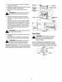
Belt Replacement
There are two drive belts and one deck belt in this unit;
follow description below to identify the belts.
•
Deck belt goes from the deck pulley to the lower
sheave in engine pulley.
•
Lower drive belt goes from the variable speed
pulley to the transmission pulley.
•
Upper drive belt goes from the variable speed
pulley to the upper sheave of engine pulley.
Periodically check if these belts are too loose or
damaged. If so, replace with new belt.
IDLE MIXTURE
VALVE
WITH
LIMITE
the cranking or charging circuit where insulation
may have rubbed through and exposed bare wire.
Replace the wire or repair with electrician's tape if
the wire strands have not been damaged. Also look
for a wire pinched between body panels, burned by
the exhaust pipe or muffler, or rubbed against a
moving part.
Stop the riding mower and engage the parking
brake. Remove ignition key.
Pivot the hood assembly up. Disconnect the spark
plug wire and ground it.
Pull the fuse out of the lead wire.
Replace with new automotive fuse.
Make sure to reconnect the spark plug wire before
pivoting the hood assembly back.
R
Deck Belt
1.
Carbureto/r
Throttle
Lever
2.
Figure 16
5.
6.
7.
Engage the parking brake and turn the ignition off.
Pivot the hood assembly up and remove the grass
catcher. Remove the spark plug wire.
Put the deck at the lowest cutting height by
adjusting the cutting height adjustment lever to the
lowest position.
Rotate carburetor throttle lever against the idle
speed screw and hold it. Turn idle speed screw to
obtain 1750 rpm, using a tachometer to measure.
Rotate idle mixture valve full travel clockwise and
then counter-clockwise. Do NOT remove limiter
Imaginary
Line
Belt
Belt
Keeper "A"
ut
caps. Do NOT force beyond limits.
Place idle mixture valve in middle of travel.
8.
Move throttle control to FAST position. The engine
should accelerate smoothly. If it does not, adjust
idle mixture valve counter-clockwise 1/8 turn.
9.
Replace the black cap on the riding mower frame
and put the hood assembly back.
Pulley
Fuse Replacement
The fuse is located next to the spark plug under the rear
frame. Fuses seldom fail without a reason. If the fuse
Screw
blows, the source problem must be corrected or the
new fuse wilt blow again.
1. Check for loose connections in the fuse holder and
Pulley
Figure 17
replace holder if necessary. A dead short may be in
19
3. Usinga 1/2"socketwrench,removetwoselftappingscrews,lockwasherandhexnutthathold
thedeckbeltcovertothedeck.SeeFigure17. For
this,youwillhavetoworkfromthetopleftsideof
theridingmower.Removethebeltcover.
4. Usinga 9/16"wrench,loosenthehexnutonthe
idlerpulley.SeeFigure17.
5. Removebeltfromarounddeckpulley,idlerpulley,
andtheenginepulley.
6. Placethenewbeltaroundthedeckpulleyandthe
enginepulleymakingsurethatthebeltis routed
insidethebeltkeepers.
Therearetwobeltkeepers
underthegrasscatcher,oneontheidlerandthe
otherunderthedeckbeltcover.SeeFigure17.
7. Reinstall
deckbeltcoverandsecurewithtwoeach
ofself-tapping
screw,lockwasherandhexnut.
NOTE:Belt keeper "A" must be mounted on the outside
of the belt.
8.
IMPORTANT: Make sure that the belt is routed inside of
belt keeper, and the belt keeper is reassembled in the
same location from where it was removed.
Upper Drive
1.
2.
3.
4.
Battery Service
•
Replace the grass catcher and pivot the hood
assembly back.
•
Remove the rear deck belt guard following first five
steps for deck belt removal. Remove belt from the
engine pulley. See Figure 18.
•
Variable Speed Pulley
Spring
Loaded
Spring
Loaded
_
•
•
•
,l_
WARNING:
Do not short battery terminals
Always keep the rubber boot positioned over the
positive terminal to prevent shorting.
Connect positive terminal first to prevent sparks
from accidental grounding.
Do not use the riding mower battery to start other
vehicles.
WARNING:
Battery posts, terminals and
related accessories contain lead and lead
compounds. Wash hands after handling.
Pulley
Figure 18
.
Shield eyes and protect skin and clothing when
handling battery acid (electrolyte) or a battery
containing acid.
Keep sparks, flame, cigarettes and other sources of
ignition away. Remember that battery contains
explosive gases.
Work in a well-ventilated area when filling
(activating), charging and using the battery.
by making a connection between either two
battery posts or between the positive terminal,
marked + on the battery, and the riding mower
frame. Before installing battery, remove metal
bracelets, wristwatch bands, rings etc. from
your person.
Idler
2.
Belt
Remove the engine pulley using a 5/8" socket
wrench with a 6" extension. The engine pulley is
located in front of the transmission.See Figure 18.
Drop the engine pulley down and remove the belt
from around it.
Push the idler bracket to the right and remove the
belt. See Figure 18.
Replace belt and reassemble.
Safe Handling
Lower Drive Belt
1.
Drop the pulley down and remove the belt.
Replace new belt and reassemble.
The battery is located under the hood assembly. The
positive battery terminal is marked (+); the negative
battery terminal is marked (-).
Make sure to align the belt keeper in line with the
frame. See Figure 17.
NOTE: An imaginary line between the belt keeper and
idler pulley should be parallel to frame. See Figure 17.
9.
4.
5.
•
Push the spring loaded idler, located on the left side
of the transmission, to the right. Remove belt from
around the idler and then the transmission pulley.
See Figure 18.
Using a 9/16" socket, remove bolt, spacer and the
flat washer from the variable speed pulley.
•
•
2O
Always keep battery cables and terminals clean
and free of corrosive build-up.
After cleaning, apply a light coat of petroleum jelly
or grease to both terminals.
If removing the battery for any reason, disconnect
the NEGATIVE (black) wire from its terminal first,
followed by the POSITIVE (red) wire.
•
Whenre-installing
battery,alwaysconnectthe
POSITIVE
(red)wiretoitsterminalfirst,followedby
theNEGATIVE
(black)wire.
IMPORTANT:
Becertainthatwiresareconnected
tothe
correctterminals;
reversing
themcouldchangepolarity
andcausedamagetotheengine'salternating
system.
To jump-start
•
1.
2.
Disconnect the positive (+) jumper cable from the
positive (+) post of the good battery.
10. Disconnect the other end of the positive (+) jumper
cable from the solenoid.
11. Replace boot over the forward most terminal from
where you removed it in Step 1. See Figure 19.
To charge the battery
the battery
If battery is new or it the riding mower has been stored
for an extended period of time, charge the battery for
one hour with a battery charger (output 6 amps) before
using your riding mower. Read safe operating
instructions on battery charger before starting this job.
NOTE: This riding moweris equipped with a remote
battery charging terminal on the solenoid on the right
side of the frame under the hood. Follow the
instructions below to use this terminal
•
•
9.
Do not jump-start directly at the battery.
Do not allow positive and negative cable clamps to
touch each other.
Do not jump-start a damaged or frozen battery.
IMPORTANT: If a charger with 6 amps output is not
available, use a lower output charger for a longer
charging period. However, do not use a charger with
higher than 6 amps output.
Pull back the boot from the forward most terminal
connected to the solenoid. See Figure 19.
Connect the positive (+) lead of the jumper cable to
this terminal. See Figure 19.
Neg. Lead of
Jumper Cable
If a charger is not available, but the battery is able to
start the riding mower, run the mower for a minimum of
one hour of mowing to charge the battery with the
engine's charging system.
NOTE: Use the remote terminal on the solenoid to
charge the battery. Do not charge at the battery.
Throttle
Bracket
1.
Pos. Lead of
Jumper Cable
2.
\
3.
Use this terminal
4.
5.
6.
7.
To Remove
Battery
1. Make sure that the riding mower is stopped
completely. Lift the hood assembly up to access the
battery.
2. Remove the wing nuts securing the battery holddown rods to the battery cover.
3. Pull the battery cover up and keep it away.
4. Loosen the screw at the negative terminal and
remove the cable.Repeat at the other terminal.
5. Remove the battery.
Rig
Wheel
Figure 19
3.
4.
5.
6.
7.
8.
Pull back the boot from the forward most terminal
connected to the solenoid. See Figure 19.
With the battery charger off, connect the positive
(+) lead of the charger cable to this terminal. See
Figure 19.
Connect negative (-) lead of the charger cable to
the throttle bracket.
Turn the battery charger on. Charge the battery
until the indicator on the charger shows full charge.
Turn battery charger off. Disconnect the negative
charger cable (marked -) from the throttle bracket.
Disconnect the positive charger cable (marked +)
from the solenoid terminal.
Replace boot over the forward most terminal (from
where you removed it in Step 1). See Figure 19.
Connect the other end of the positive (+) jumper
cable to the positive (+) post of the good battery.
Connect one end of the negative (-) jumper cable to
the negative (-) post of the good battery.
Connect the other end of the negative (-) cable to
the throttle bracket. See Figure 19.
Start the tractor and leave it running to charge the
battery.
Disconnect the negative (-) jumper cable from the
tractor.
Disconnect the other end of the negative (-) jumper
cable from the negative (-) post of the good battery.
Attaching
1.
2.
21
Battery Cables
Remove wing nut on the battery hold-down rod at
each end of the battery cover. See Figure 20.
Remove the battery cover from the battery to
access the terminals.
3.
4.
5.
_
Pull the boot up and remove screw from positive
terminal with a wrench.
Attach the red battery cable to this positive terminal
and tighten securely. See Figure 20.
Remove screw from negative terminal with a
wrench.
Wing Nut -_b
!_
Negative
Terminal _
Positive
Terminal
WARNING:
Be careful not to contact any
adjacent metal part or short across posts.
.
7.
_
Attach the black battery cable to this negative
terminal on the battery and tighten securely. See
Figure 20.
Screw
Reposition the battery cover on top of the battery,
making sure it goes over the flange of the nearby
heat shield. See Inset A in Figure 20. Tuck away
the battery cables completely under the battery
cover. See Inset B in Figure 20. Check to ensure
that the cables pass easily through slots in the
battery cover.
ARNING:
Cable
A
Keep battery cables away from
Figure 20
the engine exhaust system.
8.
9.
,_
Fuel Filter
Reinstall wing nuts on the battery hold-down rods
and tighten.
Place right hand on the left side of the seat and
slowly lower the hood assembly until fully closed.
WARNING:
,_
WARNING:
Drain fuel
tank or
close
fuel
shut-off valve before
replacing
fuel
filter.
Otherwise fuel can leak creating a fire/
explosion hazard.
Battery posts, terminals and
Your unit is equipped with a replaceable in-line fuel
filter. Loosen the clamps and replace filter whenever
contamination or discoloration is noticed. See Figure
21. Order replacement filter from Sears service, center.
related accessories contain lead and lead
compounds. Wash hands after handling.
CAUTION: Do not place your hand around the bottom
edge of the hood assembly; it may get pinched between
the hood assembly and grass catcher or the frame rail.
2_Fuel
Clam
Figure 21
22
Filter
Clamp
If the machine is to be inoperative for a period longer
than 30 days, prepare for storage as follows.
3.
4.
Battery
1.
2.
3.
Charge battery fully. The battery loses some of its
charge each day when the unit is not used. NEVER
store battery without a full charge. Recharge
battery before returning to service or every two
months, whichever occurs first.
When storing unit for extended periods, disconnect
battery cables and remove the battery from the unit.
Clean dirt and chaff from cylinder, cylinder head
fins, blower housing, rotating screen and muffler.
5.
6.
Riding Mower
1.
2.
Engine
Engines, stored over 30 days, need special attention to
prevent gum formation in the fuel system or on the
carburetor.
1.
2.
3.
If fuel tank contains oxygenated or reformulated
gasoline, that is gasoline blended with alcohol or
ether, run engine until dry.
If fuel tank contains gasoline, either run engine till
dry or add an additive to the gas. If you are using
Trouble
Excessivevibration
Mower will not
discharge grass or
leaves uncut strips
Broken Belt
additive, run the engine for several minutes to
circulate the additive through the carburetor.
Change oil on a warm engine.
Remove spark plug and pour about one ounce of
engine oil into cylinder. Replace the spark plug and
crank engine slowly to distribute the oil.
Clean engine of debris, chaff or grass clippings.
Store engine and riding mower in a clean, dry area
far away from stove, furnace, water heater or
similar appliances using a pilot light or any other
sparking device.
4.
Clean the engine and the entire unit thoroughly.
Lubricate all pivot points. Wipe the entire machine
with an oiled rag to protect the surfaces.
Transport the mower with fuel tank empty. Store
unit in a clean, dry area. Do not store next to
corrosive materials, such as fertilizer.
When storing any type of power equipment in an
unventilated or metal storage shed, care should be
taken to rustproof the equipment. Using a light oil or
silicone, coat the equipment, especially any chains,
springs, bearings and cables.
Possible Cause
Remedy
1.
Bent or damaged blade
1.
2.
Bent blade.
2.
1.
2.
Engine speed low.
Speed selection.
1.
2.
3.
4.
Cutting height set too low.
Blades short or dull.
3.
4.
1.
Sudden stop or shock load to belt
1.
2.
incorrect belt used
2.
3.
Belt engaged abruptly
3.
4.
Defective or damaged belt
4.
23
Stop engine immediately. Check all
pulleys, blade adapters, keys and bolts for
tightness and spindle damage. Tighten or
replace any damaged parts.
Stop engine immediately. Replace
damaged blade. Only use original
equipment blades.
Throttle must be set at FULL.
Use lower ground speed. Slower the
ground speed, better the quality of cut.
Raise the deck.
Sharpen or replace blades (uncut strip
problem only).
Inspect rider for cause such as foreign
objects stuck in between deck and frame or
belt path. Remove obstruction and check
for damage. Replace belt if needed.
Replace with proper belt. Check Parts list
in this manual for correct part number.
Engage belt slowly by depressing the
blade engagement pedal slowly.
Replace with proper belt.
Trouble
Possible
Cause
Remedy
Belt comes off
1.
2.
Belt too loose; stretched
Broken or weak idler spring
1.
2.
Readjust belt. Replace if needed.
Replace. Order with correct part number
from Parts List in this manual.
Belt shreds
1.
Belt guides or guards incorrectly adjusted
1.
2.
Pulleys not aligned
2.
3.
Pulley rusted or in otherwise bad condition;
frozen bearing
3.
Adjust belt guides and guards so that these
are approximately 1/16 to 1/8 inch from belt
when engaged.
Realign pulleys to be within approximately
1/16 inch of each other. Check with straight
edge. Make sure fastening hardware is
tight.
Replace pulleys. Order with correct part
number from the Parts List in this manual.
Adjust new pulleys to 1/16 ".
1.
1.
2.
Blade engagement pedal engaged and/or brake
pedal not engaged
Battery installed incorrectly
2.
3.
Battery dead or weak.
3.
4.
Blown fuse or circuit breaker
4.
5.
Engine ground wire loose.
5.
1.
Throttle/choke
1.
2.
3.
No fuel to the carburetor
Fuel line or in-line fuel filter plugged
2.
3.
4.
No spark to spark plug
4.
5.
Faulty spark plug
5.
6.
Dirty air cleaner
6.
1.
2.
Engine oil has been overfilled
Dipstick not seated or broken
1.
2.
Engine will not crank
Engine cranks but will
not start
Engine smokes
not in starting position.
Brake pedal must be depressed and blade
engagement pedal disengaged.
Install the battery with negative terminal
attached to the black ground wire. Attach
the positive terminal to the red wire which
goes to the solenoid. Charge the battery
fully before installation.
Check fluid level in battery. If fluid level is
low, fill to just below split rings with water.
Charge with 6 Amp. charger until fully
charged. If this does not work, replace
battery.
Replace fuse following instructions on
page 19.
Make sure the black ground wire runs from
engine to frame or mounting bolt.
Place throttle control/choke in correct
position.
Gasoline tank empty. Fill with gasoline.
Remove and clean fuel line. Replace filter if
necessary.
Spark plug lead disconnected. Connect
lead. Hold spark plug lead away from
engine block about 1/8". Crank engine.
There should be a spark. If not, have
engine repaired at Sears or other qualified
service centers.
To test, remove spark plug. Attach spark
plug lead to spark plug. Ground the spark
plug body against the engine block. Crank
the engine. The spark plug should fire at
the electrode. Replace if it does not.
If the air cleaner is dirty, the engine may
not start. Clean or replace as needed.
Check oil level.
Replace defective part.
NOTE: If you need further assistance, call the Craftsman Help line at 1-800-659-5917.
24
Parts List for Craftsman
Riding Lawn Mower Model 247.27022
48
27
18
1.
4O
#
/
/
33
37
41
37
\
46
15
25
Parts List for Craftsman
Key No. Part No.
1.
17962
2.
650-0007
Riding Lawn Mower Model 247.27022
Description
Key No,
Part No.
26.
735-0674
Switch Plate
Description
Floor Pad: LH
Steering Tube Assembly
27.
735-0266A
Floor Pad: RH
3.
4.
683-0033A
683-0178A
Steering Support Bracket
28.
736-0105
Bell Washer
Front Axle Assembly: RH
29.
736-0119
Lock Washer
5.
6.
7.
8.
9.
10.
11.
12.
683-0179A
710-0224
710-0459A
710-0643
710-0689
710-0837
71O-O958
710-1017
Front Axle Assembly: LH
30.
736-0160
Flat Washer
HexScrewAB
31.
736-0169
Lock Washer
Hex Screw 3/8-24 x 1.5" Gr.5 Sp.
Lock Screw 5/16-18 x 1.0" Gr.5
32.
33.
736-0187
736-0196
Flat Washer
Hex Screw 1/2-13 x 0.75"
34.
736-0242
Belleville Washer
Oval C-Sunk Screw #10-16 x 0.625"
35.
736-0272
Flat Washer
Hex Screw 1/4-20 x 1.25 Gr.5 Sp.
36.
736-0320
Flat Washer
AB Screw 1/4-14 x 0.625"
37.
736-3078
Flat Washer
13.
14.
710-1611B
710-3008
Self-Tapping Screw 5/16-18 x 0.75"
38.
737-3007
Grease (not serviceable)
Hex Screw 5/16-18 x 0.75"
39.
738-0541
Spacer
15.
16.
17.
712-0116
712-0206
712-0241
Lock Nut 3/8-24
Hex Nut 1/2-13
40.
41.
738-3089A
741-0225
Steering Adapter
Hex Nut
42.
741-0356
18.
19.
20.
21.
22.
712-0267
712-0324
Hex Nut
43.
747-0955
Bearing: Steering Column
Tie Rod
Lock Nut 1/4-20
44.
748-0290
Pinion Gear
712-0411
Lock Nut
Jam Nut
714-0470
Cotter Pin
45.
46.
47.
750-0532
783-0411
783-0565C
Spacer
712-0711
23.
24.
723-0156
Ball Joint
726-3046
Ratchet Clip
48.
49.
783-04234
731-1649
25.
731-0511
Trim Strip
NOTE: For painted parts, please refer to the list
of color codes below. Please add the applicable
color code, wherever needed, to the part number
to order a replacement part. For instance, if a
part numbered 700-xxxx is painted Powder
Black, the part number to order would be 700xxxx-0637.
Powder Black: 0637
Oyster Gray: 0662
Sears Red: 0721
26
Flat Washer
Hex Flange Bearing
Gear: Steering Segment
Upper Frame Cover
Lift Plate
Axle Cap
Parts List for Craftsman
Riding Lawn Mower Model 247.27022
14
22
44
/
21
23
51
43
\
10
27
/
/
\
42
\
/
\
./
/
\
\
\
41
/
/
/
/
/
12
6
/
/
/
\
\ 28
4O
40
13
34
31
27
/
/
Parts List for Craftsman
Part No.
Key No.
1.
683-0155A
2.
683-0161
Riding Lawn Mower Model 247.27022
Description
Brake Pedal Assembly
Key No.
Part No.
28.
736-0187
Description
Flat Washer
Shift Cam Assembly
29.
736-0262
Flat Washer
3.
4.
683-0275A
Deck Pedal Assembly
30.
736-0272
Flat Washer 510 X 1.00 X 060
683-0310A
Variable Pedal Assembly
31.
736-0300
Flat Washer
5.
6.
7.
8.
9.
10.
11.
12.
710-1017
Ab Screw 1/4-14 X .625
32.
736-0329
Lock Washer
711-0701
Clevis Pin
33.
736-0608
711-1156
Shaft
34.
736-3000
Spring Washer
Flat Washer
712-0287
Hex Nut 1/4-20
35.
736-3019
Flat Washer .531 X 1.062 X .134
712-0324
Lock Nut 1/4-20
36.
736-3020
Flat Washer .271 X .630 X .065
712-3017
Hex Nut 3/8-16
37.
738-0255
Shoulder Screw .375 Dia X .18
714-0104
Internal Cotter Pin
38.
738-0373
Shoulder Screw
714-0111
Hairpin Clip
39.
738-0974
Shoulder Screw .375 X .380 X 1/4-20
13.
14.
714-0470
720-0166
Hairpin Clip
Ball Knob
40.
41.
741-0591
746-0935A
Flange Bearing
Shift Cable
15.
16.
17.
726-0100
Push Cap
42.
746-0936
Variable Drive Cable
726-0450
Plug Cap
43.
746-0937
Brake Cable
731-0405
Snap-on Bushing
44.
746-0940
Deck Cable
18.
19.
20.
21.
22.
731-1913
Stop Lever
45.
746-04074
Throttle Choke Cable: 56"
732-0815A
Extension Spring
46.
747-0963A
Brake Rod
732-0865
Torsion Spring
47.
747-0964
Brake Lock Out Rod
735-0261
Drive Pad
48.
750-0736
735-0262
Deck Pad
49.
783-0473
Shoulder Spacer
Brake Lock Out Bracket
23.
24.
735-0263
Brake Pad
50.
783-0525
736-0117
Flat Washer 3/8 X .620 X .033
51.
783-0593A
Self-Propelled Pedal Link
Shift Lever
25.
26.
27.
736-0133
Flat WasherA11 x 1.25" x .100
52.
783-0794
Bracket: Lock-Out Pedal
736-0159
5/16 Washer
53.
726-0157
Cable Tie
736-0169
Lock Washer
54.
736-0270
Bell Washer
NOTE: For painted parts, please refer to the list
of color codes below. Please add the applicable
color code, wherever needed, to the part number
to order a replacement part. For instance, if a
part numbered 700-xxxx is painted Powder
Black, the part number 1o order would be 700xxxx-0637.
Powder Black: 0637
Oyster Gray: 0662
Sears Red: 0721
28
Parts List for Craftsman
Key No.
Part No.
1.
683-0152
2.
683-0194A
3.
4.
Riding Lawn Mower Model 247.27022
Description
Key No.
Part No.
Description
Pivot Link Assembly
Lift Arm Assembly
16.
17.
732-0829
732-0837
710-0376
710-3230
Hex Screw 5/16-18 X 1.00 Gr.5
18.
736-0119
Torsion Spring
Lock Washer 5/16
19.
736-0140
Flat Washer .385 LD, x .620 O.D.
5.
6.
711-0332
711-04158
Lift Bracket Pin
20.
736-0169
711-3319
21.
22.
736-0257
736-0275
Lock Washer
Flat Washer
7.
Lift Rod
Ferrule
8.
712-0266
Jam Nut
23.
736-3019
Flat Washer
9.
10.
712-3008
712-3010
Jam Nut 3/8-16 Gr. 5
Hex Nut 5/16-18
24.
25.
738-0145
738-0183
Shoulder Screw
Shoulder Screw
11.
712-3048
Jam Nut
26.
738-0958
Shoulder Spacer
12.
714-0104
Cotter Pin
27.
783-0435
13.
714-0147
Cotter Pin
28.
783-04320
14.
714-3010
Cotter Pin
29.
783-0440
Upper Deck Link
Axle Bracket: Rear
Lower Link
15.
720-0298
Handle Grip
30.
783-0442A
Crossbar Link: Lift
Hex Bolt 1/2-13 X 2.75 Gr.5 Spec.
Extension Spring
I
Flat Washer 5/16
NOTE: For painted parts, please refer to the list of color codes below. Please add the applicable color code,
wherever needed, to the part number to Order a replacement part. For instance, if a part numbered 700-xxxx
is painted Powder Black, the Part number to order would be 700-xxxx"0637. I
Powder Black: 0637
Oyster Gray: 0662
Sears Red: 0721
29
Parts List for Craftsman
Riding Lawn Mower Model 247.27022
/
/
8
10
11
#
\
KsyNo.
Part No.
1.
629-0865
Harness Assembly Adapter
2.
710-1208
Hex TT Screw 5/16-18 x 3.50
3.
710-0227
Hex Washer Head Self-Tap.Scew
4.
710-0805
Hex Screw 5/16-18 x 1.5 Gr. 5
710-0642
NOTE: For painted parts, please refer to the list
of color codes below. Please add the applicable
color code. wherever needed, to the part number
to order a replacemenl part. For instance, if a
part numbered 700-xxxx is painted Powder
Black. the part number to order would be 700xxxx-0637.
_owder Black: 0637
3O
, Thd. Forming Scr. 1/4-20x .75
.
712-3010
Hex Nut 5/16-18
7.
714-0115
Cotter Pin
726-0320
Insulator Nut Plate
,736-0289
Shoulder Bushing
8.
9.
Oyster Gray: 0662
Sears Red: 0721
Description
10.
736-0119
Lock Washer 5/16
11.
736-3000
Flat Washer
12.
750-1064
Spacer
13.
783-0591
Traesaxle Bracket
14.
783-0433A Shift Lever
Parts List for Craftsman
Riding Lawn Mower Model 247.27022
2
ts_
J
J
17
10
19
J
23
77
,J
28
NOTE: For painted parts, please refer to the list
of color codes below. Please add the applicable
color code, wherever needed, to the part number
to order a replacement part. For instance, if a
part numbered 700-xxxx is painted Powder
Black, the part number to order would be 700xxxx-0637.
Powder Black: 0637
Oyster Gray: 0662
Sears Red: 0721
Key No.
1.
2.
Part No.
Idler Bracket Assembly
710-0191
3.
4.
710-0314
Hex Screw (Special)
Hex Screw 7/16-20 x 1.0"
710-0902
Hex Screw 3/8-24 x 3.75"
5.
6.
7.
8.
9.
710-1611B
TT Screw
710-3096
Hex Screw 3/8-16 x 2.0"
712-0116
Jam Lock Nut
712-0241
Hex Nut 3/8-24
712-3017
Hex Nut 3/8-16
10.
11.
12.
712-3035
Jam Nut 9/16-18
736-0322
Flat Washer
717-0884
Variable Speed Pulley Assembly
13.
14.
15.
16.
732-0814
Extension Spdng
732-0815A
Key No.
17.
18.
19.
20.
21.
22.
23.
24.
25.
26.
27.
28.
29.
30.
31.
32.
Description
683-0147A
736-0217
Extension Spring
Lock Washer
736-0171
Lock Washer
31
Part No.
Description
736-0219
Bell Washer
736-0247
Flat Washer
736-0427
737-3007
Beleville Washer
Grease
737-0288
Grease (not serviceable)
736-0966
Shoulder Spacer
741-0405
Thrust Bearing
760-0706
SIv. Spacer
V-Belt
764-0463
766-0116
Idler Pulley
766-0660
Transmission
766-1169
Engine Pulley
766-0981A
Flat Idler Pulley
763-0526
763-0529
Idler Bracket: Vadable Speed
Cable Bracket
683-0149B
Frame Assembly
Pulley
Parts List for Craftsman
Riding Lawn Mower Model 247.27022
13
7
\
\
/
1
12
\14
4
/
/ 3
/
5\
2
\
,o,
\
\
Key No.
1.
2.
3.
4.
5.
Part No.
Differential Assembly: Single Speed
618-0072B
Upper Housing Assembly
611-0114
Detent Shaft Assembly
661-0006
Brake Yoke Assembly: LH
Hex Washer Hd. TT Screw 1/4-20 x 2.37 Gr.5
6.
7.
8.
9.
710-1206
10.
11.
12.
13.
14.
15.
Description
618-0232
618-0248
Drive Shaft assembly: LH Brake
710-1325
717-0678
Hex Washer Hd. TT Screw 1/4-20 x 1.65
719-0313B
Lower Housing
732-0863
Spring Detent
Grease
737-0148
Brake Puck
741-0862
761-0202
777-6318
Ball Detent
618-0251C
Transmission Assembly, Complete
Brake Disc
Label (not serviceable)
32
/
Parts List for Craftsman
Riding Lawn Mower Model 247.27022
13
/
\
-'
/
only
28
19
Key No. Part No.
1.
683-0142
2.
683-0160
3.
683-0163A
4.
5.
6.
7.
8.
9.
10.
11.
12.
13.
14.
683-0264A
710-0599
710-1017
710-1611B
711-0332
711-1165
714-0104
714-0147
714-0470
725-0157
732-0829
Description
Key No.
Pivot Bar Assembly
Bracket Assembly: Hood Pivot
Steering Support Bracket
Channel Assembly: Front Frame
TT screw 1/4-20 x 0.5"
AB Screw 1/4-14 x 0.625"
TT Screw 5/16-18 x 0.75"
Clevis Pin
Clevis Pin
'
'
Part No.
Description
15.
16.
735-0199A
735-0271
Rubber Bumper
Bumper
17.
18.
19.
20.
21.
22.
23.
736-0101
736-0187
736-0275
736-3019
747-0985
783-04231
783-04248
783-04252
783-0554
783-0564A
783-0605
783-0811A
Flat Washer
Flat Washer
Flat Washer
Flat Washer
Deck Rod
Rail: Rear Frame
Cotter Pin
Hairpin Clip
24.
25.
Cotter Pin
Cable Tie
26.
27.
Extension Spring
28.
Rail: Frame RH
Rail: Frame LH
Cam Bracket
Frame: Upper Front
Stabilizing Bracket: Deck
Front Bumper
NOTE: For painted parts, please refer to the list of color codes below. Please add the applicable color code, ]
wherever needed, to the part number to order a replacement part. For instance, if a part numbered 700-xxxx is
painted Powder Black the part number to order would be 700-xxxx-0637.
I
Powder Black: 0637
I
Oyster Gray: 0662
Sears Red: 0721
33
26
Parts List for Craftsman
Riding Lawn Mower Model 247.27022
I"
15
23
\
21
1
\
43
-\
1"
22
\
36
.2O
41
4_
34
33
Parts List for Craftsman
Key No.
1.
2.
3.
4.
5.
6.
7.
8.
9.
10.
11.
12.
13.
14.
15.
16.
17.
18.
19.
20.
21.
22.
23.
24.
Pad No.
683-0190B
683-0191B
683-04018
710-0157
710-0599
710-0604A
710-0654A
710-1237
710-1314A
710-1611B
710-1502
711-04143
712-0271
712-0291
712-0397
721-0208
751-3140
722-3022
725-0157
726-0205
726-0209
731-04282
731-0707A
751-3141
Riding Lawn Mower Model 247.27022
Key No,
Description
25.
26.
27.
28.
29.
30.
31.
32.
33.
34.
35.
36.
37.
38.
39.
40.
41.
42.
43.
44.
45.
46.
47.
48.
Rail Support: Frame Assembly RH
Rail Support: Frame Assembly LH
Frame Assembly
Hex Bolt 5/16-24 x 0.75"
TT Screw 1/4-20 x 0.5"
TT Screw 5/16-18 x 0.625"
TT Sems Screw 3/8-16 x 1.0"
T Screw #10-32 x 0.625"
Soc. Hd. Screw 5/16-18 x 0.75"
TT Screw 5/16-18 x 0.75"
AB Screw 8-18 x 0.375"
Battery Hold -Down Rod
Sems Nut
Hex Lock Nut 1/4-20
Wing Nut
Exhaust Gasket
Oil Drain
Foam Tape: 0.625 x 0.25 thk.
Cable Tie
Hose Clamp
Cable Tie
Plen
Battery Cover
Oil Drain Hose
3
736-0119
736-0222
736-0123
736-0607
737-0169
737-0125
741-0516
751-0535
751-3071
751-3214
751-9986
751B213146
751B222261
783-04100
783-04144
783-04260
783-0809B
725-1704
783-04358
783-04347
710-0653
723-3066
710-1017
751-3142
Part No.
®
5
11
10
4
\
Pad NO.
®
35
SAE 30W Oil (not serviceable)
Elbow Fitting
Flange Bearing
Fuel Line Hose
Fuel Cap
Fuel Tank
Muffler
Clamp Casing: Throttle
Muffler Deflector
Tank Bracket
Support Bracket RH
Support Bracket LH
Support Bracket: Transaxle
Battery (not shown)
Heat Shield
Bracket
Bolt
Fuel Hose Insulation
Trus. Screw 1/4-14 x 0.625"
Oil Drain Cap
Description
Rear Wheel CompL
634-0169A
734-1727
Front Wheel CompL
Rear Tire
734-1382
Front Tire
734-0255
Valve: Tubeless Air
737-0211A
Grease Fitting
741-0353
Flange Bearing
634-0138
Rim Assembly
734-1455A
Rim Assembly
Hex Bolt 5/16-24 x .75"
736-0242
5
Lock Washer 5/16
External Lock Washer
Flat Washer
Lock Washer 1/4
634-0139
710-0627
\
Description
714-0115
Beleville Washer
Cotter Pin
736-0285
Flat Washer
736-0156
Flat Washer
731-0484A
Hub Cap (not shown)
Parts List for Craftsman
Riding Lawn Mower Model 247.27022
NOTE: For painted parts, please refer to the list
of color codes below. Please add the applicable
color code, wherever needed, to the part number
to order a replacement part. For instance, if a
part numbered 700-xxxx is painted Powder
Black. the part number to order would be 700xxxx-0637.
Powder Black: 0637
Oyster Gray: 0662
Sears Red: 0721
15
.f
v
3"
Key No.
1.
2.
3.
4.
5.
6.
7.
Part No.
710-0599
8.
9.
Key No.
10.
11.
Part No.
783-0447
783-0448
Description
Hood Bracket
Hood Bracket: Reinforcement
710-1315
Description
TT Screw 1/4-20 x 0.5
TT Screw 3/8-16 x 1.25
710-1017
Torx AB Screw 1/4-14 x 0.625
12.
783-0449A
720-0238
Rod End Grip
13.
783-0451A
Hinge Bracket: Rear
Pivot Plate: Rear Hood
731-0511
Trim Strip
14.
783-0545
Hood Screen
731-1691A
Grass Bag Lens
15.
783-0410
783-0562
757-04016
Hinge Bracket: Front
Seat: Low Back
783-0445
Bracket Reinforcement:
Hood
738-04008
Spacer
783-0446
Plate: Hood
Hood
16.
17.
36
Parts List for Craftsman
Riding Lawn Mower Model 247.27022
Key No.
8
35
\
NOTE: For painted parts, please refer to the list
of color codes below. Please add the applicable
color code. wherever needed, to the part number
to order a replacement part. For instance, if a
part numbered 7O0-xxxx is painted Powder
Black. the part number to order would be 700xxxx-0637.
Powder Black: 0637
Oyster Gray: 0662
Sears Red: 0721
37
Part No.
Description
1.
618-0250
Spindle Assembly
2.
683-0150E
3.
683-0159
4.
5.
683-0173
710-0134
Deck Assembly
Brake Bracket Assembly
Deck Belt Cover
6.
710-0191
Cardage Screw 1/4-20 x .62"
Hex Bolt 3/8-24 x 1.25"
7.
710-0347
Hex Screw 3/8-16 x 1.75"
8.
710-0599
Self-Tapp. Screw 1/4-20 x .5_
9.
710-0650
Self-Tapp. Screw 5/16-18 x .75"
10.
710-0672
Hex Cap Scr. 5/16-24 x 1.25"
11.
710-0932
12.
710-1611B
Carriage Screw
Torx Screw 5/16-18 x .75"
13.
14.
712-0241
712-0397
15.
712-0417A
Wing Nut
Flange Nut 5/8-18
16.
712-3017
Hex Nut 3/8-16
17.
712-3057
Hex Nut 5/16-24
18.
714-0115
Cotter Pin
19.
726-0201
Speed Nut
20.
726-0233
Push Nut
21.
732-0429A
22.
736-0101
Extension Spring
Flat Washer 3/8 x 1.00 x .030"
23.
736-0119
Lock Washer 5/16
24.
25.
736-0169
736-0173
Lock Washer 3/8
26.
736-0289
27.
736-0300
Bushing
Flat Washer .406 x .875 x .059"
28.
736-0343
Flat Washer .330 x 1.25 x .120"
29.
736-3020
30.
738-0968
32.
742-0651
Flat Washer
Spacer
Three-in-one
33.
747-0957
Link Rod
34.
747-0972
Belt Keeper
35.
747-1172
36.
754-0754
Belt Keeper
V Belt
37.
756-0627
38.
783-0463A
Flat Idler Pulley
Idler Bracket
39.
783-0529
Cable Bracket
40.
783-0569B
Deck Plate
41.
783-0594
Deck Cable Plate
Hex Nut 3/8-24
Flat Washer
Blade
Parts List for Craftsman
Riding Lawn Mower Model 247.27022
Key No.
1.
2.
3.
4.
5.
6.
7.
8.
9.
10.
11.
12.
13.
Part No.
631-0084
Description
Grass Bag Assembly
Pan Hd. Machine Screw 1/4-20 x 0.5
710-0286
710-0564
710-0825
Hex Screw 1/4-20 x 2.75
712-0298
Jam Nut
712-0397
Wing Nut
Push Nut
Hex Screw 1/4-20 x 3.75
726-0271
731-1743A
Chute: Bagger
731-1744
Discharge Chute: Side-Discharge
731-1745A
Mulching Plug
Flat Washer
736-0173
736-0329
783-0645A
Lock Washer
Deflector Plate: Bagger Chute
2
/
13
_/
7
i4
10
,,
3
NOTE: For painted parts, please refer to the list
of color codes below. Please add the applicable
color code wherever needed, to the part number
to order a replacement oart. For instance if a
part numbered 700-xxxx is painted Powder
Black. the part number to order would be 700xxxx-0637.
Powder Black: 0637
Oyster Gray: 0662
Sears Red: 0721
38
Parts List for Craftsman
Riding Lawn Mower Model 247.27022
=j
/
7
E_
\
Key No.
Part No.
Description
Key No.
Part No.
Description
1.
629-04055
Harness Assembly w/o relays
7.
725-1426
Solenoid 12 volt, 100 amp.
2.
3.
710-0134
710-3021
Carriage Screw 1/4-20 x 0.62"
D Screw 5/16-18 x 0.625"
8.
9.
725-1643
725-1657A
Spring Switch
Switch:Interlock
4.
712-0271
Sems Nut 1/4-20
10.
736-0607
Lock Washer 5/16
5.
6.
725-0267
725-04040
Ignition Switch: 5 Pin
Seat Switch
11.
725-1704
Battery (not shown)
Q
.r,_2
4
\
\
Key No.
Part No.
1.
631-04028
Steering Wheel: 3Spoke
2.
731-04039
Steering Wheel Cap
3.
731-1919
Steering Column: Black
4.
731 -1857
Control Knob
5.
712-0142
Hex Nut 8-32
6.
710-3217
Pan Head Machine Screw #8-32
7.
710-0599
Hex Screw TT 1/4-20 x .50"
Description
NOTE: For painted parts, please refer to the list of color
codes below.
Please add the applicable color code,
wherever
needed, 1o the part number 1o order a
replacement part. For instance, if a part numbered 700xxxx is painted Powder Black, the part number to order
would be 700-xxxx-0637.
Powder Black: 0637
Oyster Gray: 0662
Sears Red: 0721
39
Briggs & Stratton
Engine 212907-0272
358 ENGINE GASKET
8@
for Craftsman
SET
868
12
8°@
OlZC
51
691
1022
_
"_'_ 4
1266
524 _
8420
40
Riding Mower Model 247.27022
Briggs & Stratton
Engine 212907-0272
for Craftsman
Riding Mower Model 247.27022
5J
1095 _'LVE
7
GASKET SET
51_
f_
1022
868
238 (3
13@
1022
6170
842 f_i _
1029
5240
54_
654_
]022
914
1119_
1023
334
4%4,_
21o/2o2i
°_1
_>_1
222_Yj_'
i
41
Briggs
& Stratton
Engine 212907-0272
for Craftsman
Riding Mower Model 247.27022
634A_
LMT/,I_IR
NUMBER
[_106
127 0
LOC_ONS105
_
118
!86_
143_
246
975
_87J
276@
601 _
536_
424 CAR_E_rCERPTAUL
404 ,
431
127_
9870
1266
95 _
117_
617_._
729
697 _
309J
801_
729A [_
78_
37
74
544
_
305_
_
305A
75 @
1070 _
802_
1005
1044_
23
42
Briggs & Stratton
Key No.
1
2
3
4
5
7
9
10
11
12
13
15
16
20
22
23
24
25
26
27
28
29
32
33
34
35
36
37
40
43
45
46
50
51
53
54
73
74
75
78
93
94
95
98
104
105
106
Part No.
697377
399265
391086
697106
697396
273280
697109
697157
697113
697110
690360
690946
697390
690947
692125
698281
222698
698371
698376
698377
698378
698375
698376
698377
698378
698469
697099
697364
692852
495856
495857
691279
691279
697352
691752
691968
690564
699016
697361
692137
690227
691148
697384
697897
690582
691003
690602
498030
691636
495800
690525
231855
690577
Engine 212907-0272
for Craftsman
Description
Cylinder Assembly
Kit: Bushing/Seal (Magneto side)
Oil Seal (Magneto side)
Sump: Engine
Head: Cylinder
Gasket: Cylinder Head
Gasket: Breather
Key No.
108
108A
117
118
121
125
127
Screw (Breather Assembly)
Tube: Breather
Riding Mower Model 247.27022
Part NO.
690464
691227
697490
697492
697535
697432
694524
130
131
690468
697452
Crankcase Gasket (.015" Thick)
Screw (Cylinder Head): 2-5/8" Lg.
Plug: Oil Drain
Crankshaft
133
137
141
141A
494381
281165
495097
699027
Oil Seal (PTO Side)
Screw (Crankcase Cover/Sump)
Flywheel
Key: Flywheel
Piston Assembly (Standard)
Piston Assembly (.010" Oversize)
Piston Assembly (.020" Oversize)
Piston Assembly (.030" Oversize)
Ring Set (Standard)
Ring Set (.010" Oversize)
Ring Set (.020" Oversize)
Ring Set (.030" Oversize)
Lock: Piston Pin
142
143
146
186
187
188
192
202
209
216
222
227
232
697491
697492
691639
698174
697098
691693
691986
691841
692208
691840
694042
691374
691842
Pin: Piston (Standard)
Connecting Rod (Standard)
Screw (Connecting Rod)
Exhaust Valve
Intake Valve
238
240
276
304
305
691843
298090
692255
496832
697102
305A
306
307
309
697103
697359
691003
693551
Governor/Oil Slinger
Tappet: Valve
Camshaft
Intake Manifold
Intake Gasket
310
311
333
334
337
690323
497608
492341
691061
491055
Stud (Carburetor)
Screw (intake Manifold)
Screen: Rotating
Screw: Rotating Screen
Washer(Flywheel)
Screw (Flywheel Guard)
Bushing: Throttle Shaft
Kit: Idle Mixture
Screw: Throttle Valve
356
358
363
383
404
431
462
474
503
697397
697151
19203
89838
691691
698937
691261
696578
691532
Kit: Idle Speed
Pin: Float Hinge
Valve: Float Needle
Seat: Inlet
505
510
513
523
691251
693699
692024
697086
Valve Spring:Intake
Valve Spring: Exhaust
Flywheel Guard
Valve Retainer
43
Description
Choke Valve
Choke Valve
Jet: Main (Standard)
Jet: Main (High Altitude)
Kit: Carburetor Overhaul
Carburetor
Plug: Welch
Throttle Valve
Kit: Throttle Shaft
Float: Carburetor
Gasket: Float Bowl
Choke Shaft Kit
Kit: Choke Shaft (Choke-a-matic)
Carburetor Nozzle (Standard)
Nozzle: carburetor (High Altitude)
Key: Timing
Hose Connector
Fuel Line
Screw (Control Bracket)
Adjuster: Rocker Arm
Link: Mechanical Governor
Spring: Governor
Link: Choke
Bracket: Control
Lever: Governor Control
Spring: Governor Link
Valve Cap
Fuel Filter
Washer: Sealing
Blower Housing
Screw (Blower Housing)
Screw (Blower Housing)
Cylinder Shield
Screw: Cylinder Shield
Starter Motor
Bolt: Starter Motor
Brush Set
Magneto Armature
Screw: Magneto Armature
Spark Plug
Wire: Stop
Gasket Set: Engine
Flywheel Puller
Wrench: Spark Plug
Washer: Governor Crank
Elbow: Intake
Washer (Starter Cable)
Alternator
Strap: Starter
Nut (Governor Control Lever)
Drive: Starter
Drive Clutch
Dipstick
Briggs & Stratton
Key No.
524
525
536
544
552
562
579
584
601
614
616
617
634
634A
635
654
691
697
718
729
729A
741
757
758
759
783
797
801
802
803
PartNo.
691032
697184
698973
692034
697144
691119
691029
697112
95162
691620
692012
692138
690802
690802
66538
690958
692407
690372
690959
691224
691335
697128
697607
697391
697392
693713
693167
691283
691286
693757
Engine 212907-0272
for Craftsman
Riding Mower Model 247.27022
Key No.
PaN NO.
830
691095
Description
Seal: Dipstick Tube
Dipstick Tube
Air Cleaner
Armature: Starter
Description
Stud: Rocker Arm
842
847
851
691031
697611
692424
Bushing: Governor Crank
Bolt: Governor Control Lever
Nut: Starter Cable
868
914
950
690968
690960
691657
Cover: Breather Passage
Hose Clamp
Cotter Pin
975
987
1005
495933
691326
697360
Crank: Governor
1022
1023
1026
272475
692492
697394
1029
1034
697395
691751
690822
Push Rod (Exhaust)
Rocker Arm
Push Rod Guide
1036
1044
1051
697221
691658
691265
Label: Emission
Screw (Flywheel)
Retaining Ring
1051A
1059
1070
698802
698516
690372
Retaining Ring
Kit-Screw/Washer
1090
1091
1095
691293
691333
691581
1119
1263
1264
691183
697124
697104
Screw (Alternator)
Reed: Breather
1266
1270
691917
697156
Seal: O Ring (intake Elbow)
Plug: AVS Counterweight
Seal: O Ring (intake Manifold)
Spring/Seal Assy. (Choke A Matic)
Spring/Seat Assembly
Spark Plug Boot
Nut (Carburetor)
Seal: Governor Shaft
Screw: Drive Cap
Pin: Locating
Wire Clip
Wire Clip
Timing Gear
Link: Counterweight
Counterweight
Pin: Counterweight
Pinion Gear
Nut (Brush Retainer)
Cap: Drive
End Cap
Starter Housing
Seal: O Ring (Dipstick Tube)
Dipstick
Spark Plug Terminal
Seal: Valve
Screw (Rocker Cover)
Screw: Float Bowl
Float Bowl
Throttle Shaft Seal
Fan: Flywheel
Gasket: Rocker Cover
Cover: Rocker Arm
Push Rod (intake)
Screw (Flywheel Fan)
Retainer
Limiter Cap
Gasket Set: Valve
Screw (Breather Reed)
Labels:
Labels On Engine:
HAZARD
SYMBOLS AND MEANINGS
Fire
Moving Parts
Explosion
Shoc_
777D07298
K ckback
777S30503
44
I
I
'91
SIGHT AND HOLD THIS PARALLEL TO A VERTICAL TREE
I '91
L _. _.
>,
I
I
'''--I
A POWER POLE
! ,9
A CORNER OF A BUILDING
I
"o "o
Ox=
o.__
E
-_=
LO
x:_o
=
0_
_Jl
c
0
_X
_do-c
0
o
_
CE
0
_-
WARNING
>
"5
_.
o
Do not mow on inclines with a slope in excess of 15 degrees (a rise of approximately 2-1/2 feet every 10 feet). A riding
mower could overturn and cause serious injury. If operating a walk-behind mower on such a slope, it is extremely difficult to
maintain your footing and you could slip, resulting in serious injury.
•-_ --_ "_ .__-_
Operate RIDING mowers up and down slopes, never across the face of slopes.
•
Operate WALK-BEHIND mowers across the face of slopes, never up and down slopes.
=o_:<=
Contenido
Ustado de partes .........................................
Medidor de pendientes ...............................
Informaci6n sobre la garantfa ......................
Practicas de seguddad en la operaci6n .......
Montaje
....................................................
Operaci6n ....................................................
P_g.
25
46
47
48
52
54
Contenido
P_g.
Mantenimiento .................................................
59
Servicio y Ajuste ...............................................
Almacenamiento fuera de temporada ..............
Sotuci6n de problemas ....................................
Atenci6n a clientes ..........................................
61
69
69
72
GARANTfA LIMITADA DE LA PODADORA MONTABLE: Pos dos (2) aSos a partir de la fecha de compra, si el equipo montable
Craftsman se mantiene, lubdca y se afina de acuerdo con las instrucciones en el manual del propietario, Sears reparar_, o
reemplazar_, sin costo para usted cualquier parte que se encuentre defectuosa en material o mano de obra de acuerdo con los
]ineamientos de la cobertura listados m_,s abajo.
Sears proporcionar_ la mano de obra libre de cargo para usted por el servicio de las partes en garantfa durante los dos a£_os
completos. Durante los primeros 30 dias a partir de la fecha de compra, no habr_ cargo por servicio al producto en su domicilio
por todo Io que est,, cubierto en esta garantia. (Ver excepciones abajo).
Para su conveniencia, el servicio de garantia EN CASA estar_ disponible despu6s de los primeros 30 dfas de la compra, pero
se cobrar_, una cuotapor la visita. Este cargo se dispensarY, si el producto se Ileva hasta un centro de servicio autorizado por
Sears. Para saber cuAI es el centro de servicio autorizado Sears m_,s cercano a su Iocalidad, por favor Ilame al 1-800-4-MYHOME(R). Esta garantfa aplica solamente mientras el producto est6 dentro de los Estados Unidos.
EXCLUSIONES
Esta garantfa no cubre:
Elementos que se desgastan por el uso norrnal_ incluyendo entre otros_ las cuchillas_ buj_as, filtros de aire_ bandas, y filtros
de aceite.
Servicios de mantenimiento estAndar, cambio de aceite o afinaci6n
Cambio de ]lantas o reparaciones causadas per pinchaduras con clavos, espinas, vidrios, etc.
Reparaciones necesarias debido al mal use por parte del operador, incluyendo entre otros, el daSo ocasionado por
arrastrar objetos mAs all_ de la capacidad del equipo montable, el impacto de otros objetos que doblen la estructura o
impacten el cigQeSal, o por forzar el motor.
Reparaciones necesarias debido a negligencia del operador, incluyendo entre otros, daSos mecAnico y el_ctrico
ocasionado por un almacenamiento no apropiado, falla por el uso de aceite de grade y/o cantidad no apropiada, falla por
no mantener limpia el Area de cubierta, libre de residuos inflamables, o por no dar mantenimiento al equipo de acuerdo con
las instrucciones contenidas en el manual del propietario.
Limpieza o reparaciones al motor (sistema de combustible) provocadas por un combustible contaminado u oxidado (viejo).
En general, el combustible debe utilizarse en un perfodo no mayor de 30 d[as a partir de su adquisici6n.
El deterioro normal y desgaste de los acabados exteriores, o reemplazo de la etiqueta del producto.
•
Equip o montable utilizado con fines comerciales o renta.
GARANTIA LIMITADA DE LA BATERIA
Por noventa (90) dias a partir de la fecha de compra, si la baterfa incluida con este equipo montable presenta defectos en
material o mano de obra y las pruebas que nosotros efectuemos determinan que la bateffa no mantiene la carga, Sears
reemplazar_, la bateria sin costo para usted. Durante los primeros 30 d[as a partir de la fecha de compra, no habr_, cargo por
reemplazar la bateria en su domicilio. Para su conveniencia, el servicio de garantfa EN CASA estarA disponible despu6s de los
primeros 30 dfas de la compra, pero se cobrarA una cuota por la visita. Este cargo se dispensarY, si el producto Craftsman se
Ileva hasta un centro de servicio autorizado per Sears. Para saber cu_J es el centro de servicio autorizado Sears mAs cercano a
su Iocalidad, por favor Ilame al 1-800-4-MY-HOM E(R). Esta garant[a sobre la bateffa aplica solamente mientras el producto
est_ dentro de los Estados Unidos. Esta garant[a le otorga derechos legales especfficos, pero usted podrfa gozar de otros
derechos en raz6n de su lugar de residencia.
Sears, Roebuck and Co.,Dept.817WA,
Hoffman Estates, IL 60179
Caballaje: ...................................
Aceite para el motor ....................
Combustible ...............................
Bujias: .........................................
Motor: ..........................................
Llave de encendido (Std.) ...........
Model nQmero ............................ 247.27022
Numero de Sede ........................................................
Fecha de compra ......................................................
Registre el nQmero de serie y la fecha de compra y
conserve en un sitio seguro para referencia futura.
10.0
48 oz. o 1.4 litros
Regular sin plomo
N/P 491055
212907-0272
N/P 725-0201
47
Felicitaciones por esta inteligente compra. Su nuevo
producto Craftsman® esta diseSado y fabricado para
aSos de funcionamiento confiable. Pero al igual que
todos los productos, puede requerir reparaciones de
vez en cuando. Y, es en esos momentos que un
Acuerdo de Garantfas sobre Reparaciones puede
haoerle ahorrar dinero y malos momentos.
Adquiera un Acuerdo de Garantfa sobre Reparaciones
ahora y protejase de complicaciones y gastos
imprevistos.
Una vez que ha comprado et Acuerdo, una simple
ltamada telef6nica es todo Io que necesita para
coordinar el servicio. Puede ltamar en cualquier
momento dfa o noche, o programar un turno para et
servicio en lfnea.
El Acuerdo consiste en 1osiguiente:
Servicio experto proporcionado por nuestros
12.000 especialistas en reparaciones.
Sears tiene ma.s de 12.000 especialistas en
reparaciones profesionales, que
Servicio Uimitado y sin cargo para piezas y
manos de obra en todas las reparaoiones
cubiertas.
tienen acceso a m&s de 4,5 millones de piezas y
accesodos de calidad. Ese es el tipo de
profesionalismo con el cual puede contar para ayudar a
prolongar la vida t_tilde su nueva adquisici6n en a_os
venideros, iCompre su Acuerdo de Garantfa sobre
Reparaciones hoy mismo!
Reemplazo de producto si su producto
cubierto por la garantfa no puede ser arreglado.
Descuento de110% sobre el precio normal del
servicio y piezas requeridas para Ilevar a cabo
et servicio no cubiertas por et acuerdo.
Asimismo, 10% de descuento sobre et precio
normal de controles de mantenimiento
preventivos.
Se aplican algunas Iimitaciones y exclusiones. Para
obtener precios e informaci6n adicional, Ilame al 1-800827-6655.
Servicio de Instalaci6n
Para la instalaci6n profesional que bdnda Sears de
artefactos dom_sticos, dispositivos de abertura de
puertas de garaje, calentadores de agua y otros
artfculos esenciales para el hogar, en los EE.UU.,
ltame al 1-800-4-MY-HOME®
Asistencia telefbnica inmediata - asistencia
tetef6nica proporcionada por un tecnico de
Sears para los productos que requieren
reparaciones dentro det hogar, ma.s
programaci6n de reparaci6n conveniente.
_
_
Sears
que
poner
ADVERTENCIA:
Este simbolo
instrucciones
seguridadLeaimportantes
no seguirse, enpodrfa
en peligro la seguridad personal
y/o laindica
propiedad
suya y dedeterceros.
y siga todas lasde
instrucciones
este manual
antes de iniciar la operaci6n de esta mAquina. En caso de no seguir estas instrucciones podria provocar lesiones
personales. Cuando yea este simbolo--siga la advertencia.
ADVERTENCIA:
La bateria
y las emisiones
del motor contienen
quimicos
que a saber del
estado de California, producen cancer, defectos de nacimiento o da5o a la salud reproductiva. La
baterfa y sus terminales contienen plomo, por Io que deberA lavarse las manos despues de entrar
en contacto con elias.
_
para
ADVERTENCIA:
construida
ser operada
acuerdo
con las una
reglas
en ladel
operaci6n contenidas enEsta
estem_quina
manual. fue
AI igual
que con cualquier
tipo dedeequipo
el_ctrico,
falladeo seguridad
error de parte
operador puede producir graves lesiones. Esta maquina es capaz de amputar manos y pies y de arrojar objetos con
gran fuerza. En caso de no obedecer las siguientes instrucciones de seguridad podria producir lesiones severas e
incluso la muerte.
Funcionamiento
1.
2.
general
Lea, enfienda y siga todas las instucciones en la
m_quina y en el manual antes de armada y operada.
Guarde este manual para consultarlo regularmente y
para ordenar partes de reemplazo.
3.
48
Familiarfcese con todos los controles y su operaci6n
apropiada. Conozca como detener la m_quina y
desactivada rApidamente.
No permita nunca que los niSos menores de 14 aSos
operen esta m_,quina. Los ni£_osmayores de 14 a£_os
deben leer y entender las instrucciones de operacion y
4.
5.
6.
7.
8.
9.
reglas de seguddad contenidas en este manual y deben
ser entrenados y supervisados por sus padres.
Nunca permita que los adultos operen esta mAuina sin
recibir antes instrucci6n apropiada.
Para ayudar a evitar el contacto con las cuchillas o una
lesi6n por algun objeto que sea arrojado, mantenga alas
personas que Io observan, a los ayudantes, nifios y
mascotas alejados al menos 25 metros de la m_,quina
mientras estA en funcionamiento. Detenga la m_quina si
alguien traspasa este radio de seguridad.
lnspeccione detalladamente el Area en donde utilizar_, el
equipo. Retire todas las piedras, palos, Ilantas, huesos,
juguetes y otros objetos extrafios que podrfan ser
recogidos y arrojados por la acci6n de las cuchillas. Los
objetos arrojados poddan ocasionar lesiones personales
severas.
Planifique el patr6n en el que va a ir descargando el
recorte para evitar que la descarga de matedal se realice
hacia los caminos, los observadores, etc. Evite ademas
descargar matedal contra las paredes y obstrucciones
que poddan provocar que el material descargado rebote
contra el operador.
Para protegerse los ojos utilice siempre anteojos o
antiparras de seguridad mientras opera la m_,quina o
mientras la ajusta o repara. Los objetos arrojados que
rebotan pueden lesionar gravemente la vista.
Utilice zapatos de trabajo resistentes, de suela fuerte y
pantalones y camisas ajustados. Las prendas sueltas o
las alhajas pueden quedar atrapadas en las piezas
movibles. Nunca opere esta m_quina estando descalzo o
con sandalias.
20. Nunca deje la m_quina en funcionamiento sin vigilancia.
Apague siempre las cuchillas, coloque la transmisi6n en
neutral, coloque el freno de mano, detenga el motor y
saque la Ilave, antes de bajarse del vehiculo.
21. Tenga cuidado al cargar o descargar la m_,quina en un
camion. Esta unidad no debe conducirse en ascenso o
descenso de rampas, porque podda ladearse y provocar
lesiones personales graves. Debe empujar
manualmente la unidad en la rampa para cargada o
descargada apropiadamente.
22. El silenciador y el motor se ca]ientan y producen una
quemadura. No los toque.
23. Revise los espacios pot encima de la cabeza antes de
conducir bajo las ramas de los arboles, cables,
cerramientos de puertas, etc. en donde el operador
podrfa atorarse o ser empujado sacAndolo de la unidad,
Io que podrta resultar en lesiones graves.
24. Desenganche todos los embragues de aditamentos,
presione el pedal de frenos completamente y cambie a
neutral antes de intentar arrancar el motor.
25. Su mAquina estA disefiada pra cortar c6sped residencial
normal, con una altura no mayor a 10". No intente cortar
c_sped demasiado crecido, seco (pastura) o pilas de
hojas secas. El c6sped y las hojas secas pueden entrar
en contacto con el escape del motor y/o acumularse en la
cubierta de la podadora, convirti6dose en un peligro de
incendio
26. Utilice solamente partes y accesorios fabricados
especialmente para esta mAquina, originales del
fabricante (OEM). Lea, comprenda y siga todas las
instrucciones proporcionadas con los accesorios o
aditamentos.
27. Los datos estadfsticos muestran que los conductores
mayores de 60 afios se yen implicados en un alto
pocentaje de lesiones relacionadas con tractores. Estos
operadores deben evaluar su capacidad para operar el
tractor en forma suficientemente segura para protegerse
a ellos mismos y a los demAs contra lesiones graves.
28. Si se presentan situaciones que no estan previstas en
este manual sea cuidadoso y use el sentido comL_n.
Contacte al centro de servicio Sears para obtener ayuda.
10. Est6 atento de la podadora y de la direcci6n de la
descarga de los aditamentos y no apunte a nadie. Nunca
opere esta podadora sin que est_n en su lugar apropiado
la cubierta de descarga o bolsa recolectora de pasto.
11. No ponga las manos o los pies cerca de las piezas
rotatorias o en la tolva de la cortadora. El contacto con las
cuchillas puede producir la amputaci6n de manos y pies.
12. Una cubierta de descarga faltante o dafiada puede
provocar el contacto con la cuchilla o lesiones por
objetos arrojados.
13. Detenga las cuchillas cuando cruce caminos de gravilla,
pasillos o caminos y cuando no est6 recortando el
c6sped.
14. Vigile el tr_nsito vehicular cuando est6 operando cerca o
en cruces de caminos. Esta m_quina no est_ disefiada
para operarse en la via pQblica.
15. No opere esta mAquina estando bajo los efectos del
alcohol o de drogas.
16. Corte el c6sped solamente con luz de dfa o con una
buena luz artificial. Nunca transporte pasajeros.
17. Desenganche las cuchillas antes de colocar la reversa.
Retroceda lentamente. Siempre mire hacia abajo y arras
antes y mientras va en reversa para evitar un accidente..
18. Reduzca la velocidad antes de dar la vuelta. Opere la
m_quina suavemente. Evite la operaci6n erratica y la
velocidad excesiva.
19. Desenganche las cuchillas, coloque el freno de mano,
detenga el motor y espere hasta que las cuchillas se
detengan por completo antes de retirar el colector de
recortes de c6sped, vaciar los recortes, destapar la tolva,
retirar cualquier residuo o desecho, o hacer cualquier
ajuste.
Funcionamiento en pendientes
Las pendientes son un factor importante que se relaciona con
accidentes de derrapes y ca/das que puede producir lesiones
graves e incluso la muerte. La operaci6n en pendientes
requiere mayor precaucion. Si no puede retroceder en la
pendiente o no siente que sea f_cil, no pode allL
Para seguridad, use el medidor de pendientes que se pagina
46 para medir la pendiente antes de operar la unidad en una
zona inclinada. Si la pendiente es mayor a 15 grados en el
medidor, no opere esta unidad allL
Haga Io siguiente:
1. Pode hacia arriba y abajo de las pendientes, no en forma
transversal. Tenga cuidado cuando cambie de direccion
cuando opere la m_quina en pendientes.
2. Est6 atento a los agujeros, rafces, rocas, objetos ocultos
o abultamientos que puedan provocar que se derrape o
se tropiece. El terreno desnivelado puede voltear la
m_quina. El c6sped alto puede ocultar obst_culos.
3. Vaya a baja velocidad. Elija una velocidad Io
suficientemente baja de modo que no tenga que
detenerse o hacer cambios mientras estA sobre la
pendiente. Las Ilantas poddan perder traccion sobre las
49
4.
5.
6.
pendientes aunque los frenos funcionen
apropiadamente. Siempre mantenga la maquina con una
velocidad seleccionada en la palanca mientras
desciende las pendientes para poder frenar con motor.
Siga la recomendaci6n del fabricante para los pesos o
contrapesos de las Ilantas para mejorar la estabilidad de
la mAquina. Tenga especial cuidado con los colectores
de recorte de c6sped u otros aditamentos, ya que
pueden modificar la estabilidad de la mAquina.
Haga que todos los movimientos en las pendientes sean
lentos y graduales. No cambie repentinamente la
velocidad ni la direcci6n. Un frenado o cambio de
velocidad repentinos pueden causar que el frente de la
mAquina se levante y de una voltereta hacia atras, Io que
podria producir lesiones severas.
Evite arrancar o detenerse en una pendiente. Si las
Ilantas pierden la tracci6n, desenganche las cuchillas y
descienda lentamente la pendiente.
e.
f.
g.
h.
2.
No haga Io siguiente:
1. No de vuelta sobre las pendientes a menos que sea
necesario. Si es asi, de vuelta lenta y gradualmente
descendiendo de la pendiente, si es posible.
2. No corte el c6sped cerca de pozos, hundimientos,
bancos, podria perder el equilibrio. La podadora podria
volcarse repentinamente si una de las Ilantas estuviera
fuera de] borde de un pozo, banco u agujero.
3. No intente estabilizar la mAquina poniendo su pie en el
piso.
4. No utilice un colector de c6sped en pendientes
escalonadas.
5.
6.
7.
Retire la Ilave cuando deje la maquina sin
atenciOn para prevenir el funcionamiento no
autorizado.
No permita nunca que los niOos menores de 14 aOos
operen esta maquina. Los ni£_osmayores de 14 a£_os
deben leer y entender las instrucciones de operaciOn y
reglas de seguridad contenidas en este manual y deben
ser entrenados y supervisados por sus padres.
Servicio
Manejo seguro de la gasolina
1.
No pode el c6sped hemedo. Una menor tracci6n podria
causar derrapes.
No haga cambios a neutral para descender. El exceso de
velocidad podria causar que el operador pierda el control
de la m_quina ocasionando lesiones graves e incluso la
muerte.
No arrastre cargas pesadas detrAs de los aditamentos
(carrito de basura cargado, podadora de rodillos, etc) en
pendientes mayores de 5 grados. Cuando descienda, el
peso adicional tiende a empujar el tractor y podr[a
ocasionar que usted pierda el control. (el tractor podria
acelerarse, reduciendo la capacidad de frenando y
maniobrabilidad, los aditamentos podrian clavarse y
hacer palanca y provocar que el tractor se voltee).
Nifios
1.
Tenga extrema precauci6n cuando se aproxime a
esquinas ciegas, entradas de puertas, arboles u
otros objetos que puedan obstaculizarle la vista
de un niOo que pudiese correr hacia la podadora.
Desenganche las cuchillas antes de colocar la
reversa. La funci6n de "No-Cortar-En Reversa"
evita accidentes, no trate de hacer que funcione
de otro modo.
Mantenga alejados a los ni£_osde los motores en
marcha o calientes. Pueden sufrir quemaduras
con un silenciador caliente.
Para evitar lesiones o da£_ossea sumamente cuidadoso
al manipular la gasolina. La gasolina es altamente
inflamable y los vapores son explosivos.. Se puede
lesionar gravemente si derrama gasolina sobre usted o
sobre la ropa ya que se puede encender. Lave la piel y
cAmbiese de ropa de inmediato..
a. Utilice solo recipientes para gasolina autodzados.
b. Nunca Ilene los contenedores en el interior de un
vehiculo o camion o caja de camioneta con
recubrimientos plAsticos. Coloque siempre los
contenedores en el piso lejos del vehicu]o antes
de Ilenarlos.
c. Cuando sea pr_ctico, retire el equipo a gasolina
del camion o remolque y II0nelo en el piso. Si esto
no es posible, Ilene el equipo en un remolque con
contenedor portatil, en vez de desde un
dispensador de gasolina.
d. Mantenga la boquilla de Ilenado en contacto con
el borde de la entrada del tanque de gasolina o
contenedor en todo momento hasta que est0
]leno. No utilice un dispositivo para abfir/cerrar la
boquilla.
e. Apague todos los cigarrillos, cigarros, pipas y
otras fuentes de combustion.
f.
Pueden ocurrir accidentes trAgicossi el operador no estA
atento a la presencia de ni£_os. Por Io general a los ni£_os
les atraen las podadoras y la actividad de podar el
c_sped. No entienden los riesgos ni los peligros. Nunca
asuma que los ni£_osperrnanecer_n en el mismo lugar
donde los vi6 por L_ltimavez.
a. Mantenga a los niOos fuera del Area de trabajo y
bajo estricta vigilancia de un adulto responsable
ademas del operador.
b. EstO alerla y apague la podadora si un ni£_o
ingresa al Area.
c. Antes y mientas se esta moviendo hacia atr_s,
mire hacia arras y cuide que no haya ni£_os.
d. Nunca transporte ni£_os,aun con la cuchilla
apagada. Podr[an caerse y resultar severamente
]esionados o interferir con la operaci6n segura de
]a m_quina.
g.
h.
i.
j.
k.
5O
Nunca cargue combustible en la maquina en un
espacio cerrado.
Nunca saque la tapa del gas ni agregue
combustible mientras el motor est_ caliente o en
marcha. Deje que el motor se enfrie per Io menos
dos minutes antes de volver a cargar combustible.
Nunca recargue el tanque de combustible. Llene
el tanque no mAs de 112pulgada por debajo de la
base del cuello del filtro para dejar espacio para la
dilataci0n de] combustible..
Vuelva a co]ocar la tapa de la gasolina y ajestela
bien.
Limpie la gasolina derramada sobre el motor y el
equipo. Traslade la maquina a otra zona. Espere
5 minutes antes de encender el motor.
Para reducir el riesgo de incendio mantenga la
m_quina limpia de pasto, hojas y de acumulacion
L
m.
de otros escombros. Limpie los derrames de
aceite o combustible y saque todos los
escombros embebidos con combustible..
Nunca almacene la maquina o el recipiente de
combustible en un espacio cerrado donde haya
fuego, chispas o luz piloto como per ejemplo,
calentadores de agua, homos, secadores de
ropa, otros aparatos a gas, etc.
Deje que la m_,quina se enfrfe 5 minutos por Io
menos antes de almacenarla.
extreme precauciones cuando le de servicio.
Mantenga todos los pernos, tuercas ytornillos bien
ajustados para asegurarse que la m_quina se encuentra
en condiciones seguras de operaci6n
8. Nunca intente violar el sistema de bloqueo de seguridad
u otros mecanismos de seguridad. Verifique
regularmente si funciona de manera correcta.
9. Despu6s de golpear con algen objeto extra£_o, detenga el
motor, desconecte el cable de la buj[a y conecte el motor
a masa. Inspeccione minuciosamente para ver si la
m_quina est_ daSada. Repare el daSo antes de arrancar
y operar.
10. Nunca trate de hacer ajustes o reparaciones a la
m_.quina mientras el motor estA en marcha.
11. Los componentes de la tolva para recorte y la cubierta de
descarga, estAn sujetos a desgaste y da£_osque podrfa
dejar expuestas partes que se mueven o permitir que se
arrojen objetos. Para proteger su seguridad, verifique
frecuentemente todos los componentes y reemplAcelos
s61o con partes de los fabricantes de equipos originales
(O.E.M.) listadas en este manual. "La utilizaci6n de
partes que no cumplan con las especificaciones de
equipos originales podrfa tenet como resultado un
rendimiento incorrecto y ademAs la seguridad podrfa
estar comprometida"
12. No cambie la configuracion del regulador del motor ni Io
opere a una velocidad demasiado elevada. El regulador
controla la velocidad m_'txima segura de operaci6n del
motor.
7.
Servicio general
1.
2.
3.
4.
5.
6.
Nunca encienda un motor en espacios cerrados o en una
zona con poca ventilaci6n. El escape del motor contiene
monoxide de carbono, un gas inodoro y letaL.
Antes de limpiar, reparar o inspeccionar la m_,quina,
compruebe que la cuchilla y todas las partes que se
mueven se ha]lan detenido. Desconecte el cable de la
bujia y p6ngalo de manera que haga masa contra el
motor para evitar que se encienda de manera accidental.
Revise peri6dicamente para asegurarse de que las
cuchillas se detengan por completo en aproximadamente
cinco (%) segundos despu_s de accionar el control de
desenganche. Si las cuchillas no se detienen en este
tiempo, su unidad debe ser reparada por un profesional
en un centro de servicio autorizado.
Revise con frecuencia el funcionamiento del sistema de
frenos ya que est,, sujeto a desgaste por la operacion
normal. Ajuste/de servicio segpun se requiera.
Revise los pemos de montaje de la cuchilla y del motor a
intervalos frecuentes para verificar que est_n bien
apretados. Adem_,s, inspeccione visualmente la cuchilla
en busca de da_os (desgaste excesivo, abolladuras,
cua[teaduras, etc)
Reemplace las cuchillas s6lo con partes de los
fabricantes de equipos originales (O.E.M.) listadas en
este manual. "La utilizaci6n de partes que no cumplan
con las especificaciones de equipos originales podr[a
tener como resultado un rendimiento incorrecto y
ademAs la seguridad podrfa estar comprometida"
Las cuchillas de las podadoras son muy afiladas y
podrfan cortar]o. Envuelva la cuchilla o utilice guantes y
13. Mantenga o reemplace las etiquetas de seguridad e
instrucciones segun sea necesario.
14. Respete las normas referentes a la disposici6n correcta
y las reglamentaciones sobre gas, combustible, etc. para
proteger el medio ambiente.
Su responsabilidad
S61o permita que usen esta m_quina el_ctrica las
personas que lean, comprendan y respeten las
advertencias y las instrucciones que aparecen en este
manual yen la m_tquina.
51
Desempaque
1.
2.
3.
4.
5.
6.
Apertura
de ventilacibn
Retire todos los tornillos y grapas de embalaje.
Sostenga los lados de la caja firmemente, levante
la parte superior y retfrela. Evite pinchar las Ilantas.
Retire y descarte la bolsa de plastico que cubre la
unidad.
Levante la parte posterior de la podadora y deje
libre et fondo de la caja. Repita por el frente.
Asegi3rese que et freno de mano no est_l colocado.
Vea en Figura 4 la ubicaci6n del freno de mano.
Deslice la unidad hasta sacarla de la caja.
Partes sueltas
Figura 1
Saque las partes suettas de la tolva para recortes y/o la
caja con mucho cuidado. Compare con la lista de
abajo.
i.Adaptador para abono y tolva de descarga lateral
ii.Manga para drenado de aceite
iii.Llaves de encendido (no se muestran)
iv.Manual det operador (no se muestra)
NOTA: Desde la posicion de funcionamiento,
observa la referencia a la derecha o a la izquierda.
3.
4.
5.
se
6.
Su podadora montable se envfa sin gasolina ni
aceite en el motor. Sin embargo, usted debe
revisar el nivet de aceite antes de ponerla a
funcionar. Tenga cuidado de no Ilenar en exceso.
Retire las dos palometas (A y Ben Figura 2 ) de los
dos extremos de la tolva para descarga de recorte.
Afloje la tuerca mariposa C en la mitad de la tolva.
No la quite.
Destice la tolva para recorte a la derecha y afuera
det marco de la cubierta. Deslice la tolva de
descarga lateral para meterla y col6queta en la
cubierta de modo que las posiciones de las tres
tuercas de mariposa se alineen con la cubierta.
Reinserte las palometas A y B. Apriete las tres.
Tolva para recorte
de c_sped
Unibn de la tolva de descarga
lateral
Descarga
Tolva
Tuer.ca de
Su podadora montable se envfa con la tolva
completamente colocada en la unidad. La tolva de
descarga lateral y et adaptador para abonadora se
incluyen por separado. Siga las instrucciones a
continuaci6n para colocar la tolva de descarga lateral.
,_
1.
2.
Tuerca de
mariposa A
ADVERTENCIA:
No oopere
no est_ln instaladas una
m_ls la
de podadora
las partes:si
tolva para recorte, tolva de descarga lateral o
adaptador para abono.
Figura 2
Suba el cofre y baje la palanca de ajuste de la
altura de corte a su posici6n mas baja.
Levante el cofre desde la parte izquierda
solamente. PArese del lado derecho de la unidad y
jale el cofre hacia usted hasta que se abra por
completo. Vea la Figura 1.
Unibn del adaptador
para abono
AI operar su podadora montable, usted tiene tres
opciones: (I) colectar los recortes de c_sped en la tolva,
(ii) descargar los recortes por un lado, o (iii) usar los
recortes para abonar el mismo cesped. Para la tercera
opci6n, una el adaptador para abono a la tolva de
descarga lateral y luego a la cubierta.
NOTA: No levante el cofre por las dos aberturas de
ventilaci6n detras de/asiento.
•
52
Coloque los dos pemos hexagonales a trav_s det
adaptador para abono en las aberturas
correspondientes. Ver Figura 3.
Tuerca de marieosa
jTolva
•
•
de descarga lateral
•
Tuerca___
_
_
•
f....L_-_
Bul6n I_xaxagonal
_
""°'oonaa°rra_
Adaptado
•
Figura 3
53
Coloque las tuercas sobre los pernos hexagonales.
Inserte el adaptador en la tolva de descarga lateral
alineando gasdos ranuras en los dos lados de la
tolva con los del adaptador.
Para unir ahora el adaptador a la unidad, siga las
instrucciones para unir la tolva de descarga lateral
a la cubierta.
Coloque una tuerca de madposa en cada uno de
los pernos hexagonales y de unas cuantas vuettas.
Ver Figura 3. Revise que et adaptador est6
alineado correctamente con la tolva de descarga.
Ajuste la tuerca a mariposa.
Conozca las propiedades
de la podadora
Compare las ilustraciones en Figura 4 con su unidad para familiarizarse con la ubicaciSn de los distintos controles
y ajustes.
_lb
ADVERTENCIA:
AI operar la podadora puede ser que objetos extraSos sean arrojados a los ojos 1o
cual puede da_arlos gravemente. Utilice siempre los anteojos de seguridad provistos antes de operar
el equipo o mientras 1oajusta o 1o repara.
Estrang ulador/Obturador
Control
i'=_Patanca
de cambios
Nivel de Ilenado de cdsped
Indicador
Altura del corte
Ajuste
Palanca
Enganche de cuchilla
Pedal
Encendido
Interruptor
Descarga lateral
Tolva
Pedal
Freno
Pedal
Corte
Cubierta
_
_,
Estacionamiento
Cuchilla
Enganche
Pedal
Freno
2_/Cespedl
_,_-[_"_
I U
II] II
/ _
I /
Cofre
Montaje
_Motor,.
Cuchina /
Seguro
.,"_ __=__,'_/_
J _/
v/
_ Bateria
NOTA: El deposito de gasolina no se demuestra aqui.
Figura 4
Control de estrangulador/obturador:
Use para
regular la velocidad del motor y arrancar et motor.
Pedal de avance: Use para regular la vetocidad de la
podadora.
Interruptor de encendido: Use para encender o
apagar el motor.
Palanca de cambios: Use para cambiar la direcciSn
de la podadora.
Indicador de Nivel de Ilenado de c_sped: Use para
determinar et nivel de recorte en la bolsa y cuando
vaciarla.
Freno de mano: Use para detener la podadora e
impedir que se mueva mientras est& estacionada.
Pedal de enganche de cuchilla: Use para enganchar
o desenganchar la cuchilla.
Seguro de la cuchilla: Use para asegurar la cuchitla
en su posici6n enganchada.
Palanca de ajuste de la altura de corte: Use para
elvar y bajar la cubierta de corte que determina la altura
de corte.
Pedal del freno: Use para detener et movimiento hacia
adelante o en reversa de la podadora.
54
•
•
•
Conozca la ubicaci6n y funci6n de todos los
controles.
Asegt_rese que las cuchillas y et motor se detengan
antes de colocar las manos o los pies cerca de las
cuchillas.
Antes de salir de la posici6n det operador,
desenganche tas cuchitlas, coloque la palanca en
neutral, coloque et freno de mano, apague el motor
y saque la ltave de encendido.
NOTA: Mire hacia atras y
aseg#rese que el camino est#
libre de obstaculos antes de
colocar la palanca en reversa.
Detencibn de la podadora
1.
2.
3.
4.
5.
.
Suette completamente et pedal de enganche de la
cuchilla.
Suette completamente el pedal de avarice y oprima
et pedal de freno.
Cuando la podadora se detenga por completo,
coloque la palanca de cambios en neutral.
Aplique el freno de mano jala.ndolo hacia arriba.
Gire la llave de encendido a la posici6n OFF
(apagado) y sAquela del encendido.
4.
Dispositivo de bloqueo de
seguridad
ADVERTENCIA:
El control de estrangulador/
obturador se usa para
aumentar o disminuir la
velocidad del motor, Las
posiciones de RAPIDO y
LENTO estan marcadas con
una liebre y una tortuga
respectivamente.
•
Para la operaci6n normal y
cuando utilice un colector
de recorte, mueva el
control a la posici6n de R,_,PIDO.
•
Para una carga m&xima de la baterfa y un motor
mas fifo, mueva el control a la posici6n de
R,_,PIDO.
•
Para transportarse y para arrastrar aditamentos,
mueva el control a la posici6n de LENTO.
Para evitar el riesgo de
tesiones, no haga funcionar la podadora
montable si et sistema de bloqueo de
seguridad presenta fallas en su
funcionamiento.
NOTA: No cambie la configuraci6n de/regulador para
aumentar o disminuir la velocidad de/ motor. El
regulador esta ajustado de fabrica para un maximo
rendimiento del motor y no debe ser modificado.
Uso de la palanca de cambios
Indicador de Nivel de Ilenado de
c sped
La palanca se utitiza para controlar la direcci6n de la
podadora montable. Puede colocarse en avance al
Frente, en Neutral o en Reversa. Estas posiciones
esta.n marcadas como F, N, y R respectivamente en la
unidad. Esta unidad est_ disefiada para no cortar
cuando la palanca est& en la posicibn R. (Si la cuchilla
esta enganchada mientras que la palanca de cambios est_
en la posici6n R, la unidad se apagara. Para volver a poner
en marcha la unidad, desenganche la cuchilla).
1.
No exija demasiado a la
palanca de cambios. Si no
hace el cambio, suette
ligeramente el pedal de
freno para alinear el collar
de cambio en la transmisi6n
y luego intente mover la palanca.
Suette lentamente el pedal de freno y quite el pie
det pedal. Asegt_rese que no hay nadie en la
trayectoria mientras estA moviendo la podadora.
Control de estrangulador/
obturador
Esta unidad esta. equipada con un sistema de bloqueo
de seguridad para su protecci6n. Los interruptores det
dispositivo de bloqueo est&n conectados al pedal de
frenos, al pedal de enganche de la cuchitla, a la
palanca de cambios y al asiento.
El sistema de bloqueo de seguridad sirve a un triple
prop6sito:
a. prevenir que el motor arranque a menos que se
presione el pedal de frenos y la cuchilla est_
desenganchada;
b. apagar el motor si la cuchitla no esta
desenganchada cuando la palanca se coloca
en reversa; y
c. apagar et motor cuando et operador sale de su
posici6n sin colocar el freno de mano.
,_
La palanca de cambios estA bloqueada en la
posici6n N. Mueva la palanca hacia afuera
(izquierda) y deslice la palanca hacia el frente o F o
hacia abajo a la posici6n de reversa, segt_n 1o
requiera.
2.
Este indicador fue disefiado
para aumentar la comodidad
de su podadora montable.
Mientras la podadora est_ en
marcha, et aire pasara a
trav_s de la tolva de
descarga hacia el colector de
cesped. Si el colector de
cesped esta vacfo, et aire
Antes de mover la palanca a cualquiera de sus
posiciones, presione el pedal de freno y detenga la
unidad. Mantenga su pie en el pedal de freno.
55
Nivel de Ilenado
Indicador
fluyefacilmente
empujando
labolahaciaarriba.Siel
colectordecespedest&Ileno,etairenofluyedejando
caerlabola.Asfquecuandovequelabolaenel
indicadordeniveldeItenado
delcolectordec_spedse
cae,debedetenerlapodadora
y vaciarlabolsa.
potencia del motor se reducira. 3-1/2% por cada 1,000
pies (300 metros) sobre el nivet del mar y 1% por cada
10 F (5.6 C) sobre 77 F (25 C). El motor operar&
satisfactoriamente en un angulo de hasta 15 grados.
Uso del Freno de mano
Modelo de motor
Para enganchar
1. Presione completamente el pedal de frenos y
detenga la unidad.
2. Con su pie derecho en el pedal de frenos, mueva la
palanca de cambios a la posici6n neutral.
3. Mantenga el pedal de frenos presionado con su pie
derecho, jale la peritla del freno de mano.
Asegerese de que el freno de mano aguanta la
unidad.
4. Suette el pedal de freno. Detenga el motor y retire
la Ilave. Ahora su podadora ya esta estacionaria.
Modelo de un s61o cilindro, enfriado pot aire. Este es
un motor de baja emisi6n.
Simbolos
usados en el motor
Mensaje
A_erta
de
Simbo_o
seguridad
_1=
Encendido-Apagado
Lea
el manual
propietario
IT_
del
I_
Aceite
Corte
de combustible
Para soltarlo
I_l
Obturaci6n
5.
Combustibteparo
Presione el pedal de freno. El freno de mano se
desenganchar& autom&ticamente.
Para conocer los significados de los simbolos de
Antes de encender
petigro, consulte la pa.gina 41.
Llenado de aceite
NOTA: En el estado de California, los motores de la
serie 210000
eubiertos
en este manual
esta
certificados por la Mesa de Recursos Ambientales de
California que cumplen con los estandares de emisidn
para 250 horas. Dicha eertificacidn no otorga al
comprador, propietario u operador de este motor,
ninguna garantia adicional con respecto al rendimiento
o vida _til de este motor. Este motor esta garantizado
dnicamente de acuerdo con las garant/as de producto y
de motor indicadas en la seeeion correspondiente en
este manual
NOTA: Su podadora montable se envfa sin gasolina ni
aceite en el motor.
Aseg_rese siempre de que el aceite en el motor es
adecuado antes de arrancar et motor. (Capacidad de
aceite: 48 oz./1.4 litros)
1. Coloque la podadora a nivel del piso y abra el co/re
para acceder al motor.
NOTA: No levante el co/re por las dos aberturas de
ventilacidn detras del asiento.
2.
3.
Di&metro 3-7/16 inch (87.31 mm.)
Carrera
2-17/64 inch (77.78 mm.)
Desplazamiento 21.00 cu.in. (344.1 cc)
Controles
del motor
=_2
1_ Tap6n ara drenado
de aceite*
2. Varilla de aceite
3.
4.
5.
6.
7.
Filtro giratorio
Ventilador
Silenciador*
Arrancador*
Filtro de aire
Saque la varilla de nivet y lfmpieta con un trapo.
Vuetva a colocar la varilla y aprietela. Vuetva a
sacar la varilta y revise la marca de nivel de aceite
en ella. El nivel de aceite debe estar en la Ifnea
FULL (LLENO) en la varitla. Vea Figura 6A. Si el
nivel esta. por debajo de eso, agregue aceite
lentamente. Vuelva a revisar el nivel con la varilla.
Si se requiere, agregue m&s aceite. Vea Figura 6B.
Tenga cuidado de no Ilenar en exceso.
A
Varilla del nivel
se
8. Filtro de gasolina
9. Carburador
10 Cable de la bujia
de encendido
* No demostrado
9
8
Figura 5
IMPORTANTE: Para una operaci6n pr&ctica, la carga no
debera exceder el 85% det caballaje especificado. La
Figura 6
56
requiere
4. Coloquelavarillaensuposici6ny aprietepara
asegurarla.
VeaFigura6C.
del Ilenado de combustible, apague el motor y d#jelo
enfriar al menos dos minutos antes de quitar el tapon
de Ilenado de combustible.
Tipo de aceite
1.
Grado de viscosidad SAE
I
30
I
I==.._
2.
Retire el tap6n de Itenado y Ilene et tanque hasta
aproximadamente 1.5 pulgadas por debajo det
cuetlo para permitir la expansi6n det combustible.
Tenga cuidado de no Ilenar en exceso.
Vuetva a colocar el tapSn en et tanque y apdete.
_.==5 N-30, 1 )W-30
I
NOTA: Si derrama combustible en el motor o en el
vehfculo, espere a que se evapore antes de arrancar el
motor.
I
II
oF .20 o
0o
Tipo de combustible
III
20 °
40 °
60 °
80°
•
100 °
_ango de temperatura de arranque esperado antes del siguiente
.'ambiode aceite
•
PRECAUCION: Los motores enfriados por aire se
_'alientan con mayor facilidad que los motores de
]utomSviles. El uso de lubricantes no sint_ticos de
Jiscosidad meltiple (5W-30, 10W-30, etc.) a temperaturas
_uperiores a los 40°F har_, que se incremente el consumo
_ormal de aceite. Cuando utilice un lubdcante de viscosidad
•
"n01tiple, revise el nivel con mayor frecuencia..
_*PRECAUCI6N: El aceite SAE 30, si se usa por debajo de
os 40°F, dar_ como resultado un arranque dificil y posibles
JaSos a los cilindros del motor debido a una lubdcacion
nadecuada.
1.
2.
3.
NOTA: Algunos combustibles,
Ilamados gasolina
oxigenada o reformulada estan mezclados con alcohol
o eter. Usar estas mezclas frecuentemente puede
da#ar el sistema de combustible
o afectar el
rendimiento. Si se afecta el rendimiento del motor, use
gasolina con un menor porcentaje de alcohol o eter.
Consulte la tabla anterior para conocer el grado
apropiado de aceite.
Use un aceite detergente de alta calidad clasificado
"Para servicio SF, SG, Sh, SJ" o superior.
No use aditivos especiales.
Encendido del motor
1.
2.
3.
NOTA: El aceite sint#tico que cumple con la
certificacion ILSAC GF-2, API y con el sfmbolo API de
servicio con "Conservacion
de energfa SJ/CF" o
superior es un lubricante aceptable a cualquier
temperatura. El uso de aceite sint#tieo no modifiea
los intervalos de cambio de aceite.
4.
5.
Bateria
6.
Normalmente la baterfa estA cargada y lista para
usarse, asf que no tendrA que cargarla antes de
arrancar. Sin embargo, si la baterfa se usa por primera
vez despu_s de la fecha mostrada en el costado de la
misma baterfa, tendra que cargarla mfnimo por una
hora a 4-6 amperes.
La baterfa se Iocaliza bajo et cofre sobre la llanta
trasera izquierda. Consulte Figura 20.
Llenado
1.
de combustible
ADVERTENCIA:
Conecte et cable de la bujfa a la misma.
Presione el pedal de freno con su pie derecho.
Coloque el control de estrangulador/obturador en la
posici6n de CHOKE (Obturaci6n) hasta adelante.
Coloque la palanca de cambios en posici6n
NEUTRAL.
Gire la ltave de encendido a la posiciSn de START
(arranque). Una vez que arranque el motor, deje
que la Ilave regrese a la posiciSn ON (encendido).
Mueva et control de estrangulador/obturador para
sacarlo de la posici6n CHOKE hasta la posici6n
FAST (rApido).
Operacibn
montable
2.
_lb
Use gasolina limpia, fresca, regular, sin plomo con
un octanaje mfnimo de 85.
No use gasolina mezclada con metanol, ni gasolina
que haya estado atmacenada por mas de 30 dfas.
Siempre compre Qnicamente el combustible en la
cantidad que podrfa utilizar en un plazo de hasta 30
dfas. El combustible fresco impide que se
acumulen residuos en el sistema de combustible o
en et carburador.
No mezcle la gasolina con aceite de motor.
Llene el tanque de
combustible en espacios abiertos bien
ventilados, lejos de chispas, llamas, pilotos u
otras fuentes de calor o encendido.
3.
4.
5.
NOTA: En una podadora montable que ya ha side
arrancada y/o operada una vez inmediatamente antes
57
de la podadora
Presione el pedal de freno para que se
desenganche et freno de mano.
Coloque la palanca de cambio en la posiciSn de
avance al Frente o en Reversa, segQn Io desee.
Mire hacia atr_s mientras retrocede.
Suette el pedal de freno.
Presione el pedal de avance.
Para detenerse, suelte completamente et pedal de
avarice y oprima el pedal de freno.
.
,_
Presione el pedal de enganche de las cuchillas
hasta que comiencen a girar. Las cuchitlas pueden
activarse con la podadora en movimiento o
detenida.
ADVERTENCIA:
3.
4.
Cuando se enganchen
tas cuchillas, mantenga los pies y manos lejos
de la abertura de descarga, las cuchiltas y
cualquier parte de la cubierta.
5.
NOTA: Su podadora montable esta equipada con un
seguro de la cuchilla para mantenerla enganchada sin
que el operador deba mantener el pedal presionado
constantemente. Vea Figura 4.
7.
Uso de la podadora montable
Para activar el seguro de la cuchilla: AI tiempo
que presiona el pedal de la cuchilla, empuje el
seguro de bloqueo de la cuchilla con su tal6n.
Debera trabarse en la posici6n de "cuchilta
enganchada". Para desactivar el seguro de la
cuchitla, presione el pedal de la cuchitla y suette et
seguro.
Obedezca las reglas de seguridad listadas en las
pAginas 3-5 de este manual para operar en forma
segura su podadora montable.
•
Antes de podar, aseg6rese de que la cubierta de
corte este nivetada. Para conocer la manera de
ajustar la cubierta, consulte la pagina 63.
•
Puede enganchar la cuchilla presionando et pedal
de la cuchilla con su pie izquierdo mientras estA en
la posici6n del operador.
•
Cuando pode un Area por primera vez, tenga
cuidado con los objetos en et cesped. Si golpea un
objeto extrafio, detenga el motor. Retire el cable de
la bujfa, inspeccione la podadora para ver que no
tenga dafios y repare cualquier dafio antes de
reiniciar la operaci6n. Repare et dafio antes de
arrancar y operar.
•
Evite maltratar et c_sped ajustando la altura de
corte y/o afitando tas cuchillas.
•
Pode con el regulador al mAximo. Conozca el
terreno en el que estA podando. Para mejores
resultados, pode cuando el pasto estA seco.
El patr6n de corte recomendado se indica a
continuaci6n:
Detencibn de la podadora
Consulte las instrucciones detalladas en la pAgina 55.
NOTA: No deje la Ilave en la posici6n ON cuando no
esta operando la podadora. Si Io hace se descargara
completamente la bated&
Para vaciar el colector de
recorte de c6sped
1.
2.
Sostenga la bolsa alejada de su cuerpo. Empuje la
palanca de la bolsa y deje que la secci6n inferior de
la bolsa caiga. Los recortes de cesped caeran por
et fondo. Vea Figura 7.
Golpee suavemente la bolsa contra et piso de
modo que las tres patas de la bolsa presionen
contra et piso. La palanca de la bolsa debe cerrarse
cuando usted presiona la bolsa hacia abajo.
Vuetva a colocar la bolsa en la podadora
asegurAndose de que se asiente en et borde en la
parte superior de la tolva de descarga. Cierre el
cofre.
Detenga la podadora completamente, coloque el
freno de mano y quite la Ilave del encendido. Salga
det asiento det operador.
Abra el cofre. Jale hacia arriba la bolsa de recorte
por la manija y ll_vela al sitio apropiado para
desecho. Vea Figura 7.
Manija de la bolsa
\
Tolva para recorte de c_sped
•
Bolsa
_/Eamq_je
•
•
Montaje
Figura 7
58
Pode el cesped frecuentemente y a intervalos
regulares de modo que solamente corte 1/3 de la
altura de la cuchitla en una sola pasada.
Para vaciar la bolsa colectora, detenga la
podadora montable per complete, aplique et
freno de mano y apague et motor. Esto impedirA
que et gas caliente del escape queme et cesped.
En muchas comunidades ya no se recogen los
recortes de cesped para desecharlos en retlenos.
Una soluci6n viable es la de usar como composta
para abono los recortes de su propio cesped. Para
esto tendra que vaciar la bolsa colectora en et sitio
designado para la elaboraci6n de composta.
Abonadora
•
la parte inferior de la cubierta porque el cesped
hQmedo tiende a adherirse a esta. Limpie la
cubierta si poda c_sped hQmedo.
Para un abono efectivo, trastape las trayectorias
para que los recortes se distdbuyan
uniformemente.
Su podadora montable esta equipada con un
adaptador para usar el recorte como abono y
reciclarlo en el mismo c_sped en vez de
recolectarlo en una bolsa.
Para mejores resultados, pode cuando el paste
esta seco. Si corta et cesped hQmedo podrfa daSar
•
Recomendaciones
i_
en general
ADVERTENCIA:
Siempre detenga et motor y desconecte la bujfa antes de limpiar o de hacer algQn tipo
de mantenimiento o ajustes. Mantenga siempre la seguridad y siga las instrucciones dadas a continuaci6n
para completar la tarea.
La garantfa de esta podadora montable no cubre elementos que hart estado sujetos al mal uso o negligencia
det operador. Para recibir et reembolso total de la garantfa, et operador deberA dar mantenimiento a la
podadora como se indica en este manual. Consulte et calendado de mantenimiento.
No recomendamos et use de una limpiadora a presi6n o manguera de jardfn para limpiar su unidad. Pueden
producir dai_os a los componentes electricos, engranajes, poleas, rodamientos o al motor. El use de agua
acortarA la vida de su podador a montable y reducira la posibilidad de reparaciones.
Calendario
de mantenimiento
Primeras 5
horas
25 horas
50 horas
100
horas
Cada
estacion
Rearrnado
Controle la hoja de la cortadora
Lubricacion de juntas, flecha de
direcci6n, engranaje
_#
Lubdcacion de enlace de cubierta,
ruedas delanteras
,_I
Cambio del aceite del motor
_
,_
Servicio al filtro de aire del motor
Servicio a la bujia
_#
,_I
Sistema de enfriamiento limpio del
motor
Cuidado
i_ll
de la cuchilla
ADVERTENCIA:
2.
proteja sus manos
usando guantes para trabajo pesado o usando
una estopa para sujetar la cuchilla. Evite
lesiones personales.
i_ll
2.
Quite la tuerca de brida hexagonal de 5/8" que
sostiene la cuchitla al mecanismo.
Saque la cuchilla de su mecanismo. Ver Figura 8.
Si la hoja est_l
Rearmado
1.
Afilado
1.
ADVERTENCIA:
desequilibrada producir61 una vibraci6n excesiva
cuando gire a alta vetocidad y puede daSar la
unidad y podrfa romperse, causando lesiones
personales.
Retiro
1.
Se puede probar la hoja balance_mdola sobre un
destornitlador o clave. Saque et metal det lado
pesado hasta que quede bien balanceada.
Cuando afile la hoja, siga et Angulo original de giro
como gufa. Es de suma importancia que cada
extremo de corte sea desbastado de igual manera
para evitar que la hoja quede desequitibrada.
2.
59
Antes de reinstalar la cuchilla en la unidad, lubrique
et mecanismo adaptador de la cuchilla usando
aceite Iigero o aceite para motor.
Alinee la "estretla" en la nueva cuchilta con la
"estrella" en et mecanismo.
3. Instalelacuchitlaconetladomarcado"Bottom"
(inferior)o conetnQmero
departehaciaetpiso
cuandolapodadoraestaenposici6ndeoperaci6n.
4. Ajustelatuercaconreborde.VealaFigura8.
2.
IMPORTANTE:Apriete de montaje de la cuchitla 70/90
pies-lbs, mAximo.
Bujia de encendido
3.
1.
2.
3.
NOTA: Para garantizar una operacion segura, todas
los pernos y tuercas deben revisarse peri6dicamente
para corregir el apriete.
4.
Cubierta
Reempiace con el depurador de aire (nQmero de
parte 698-973)
Reensambie el depurador de aire.
Limpie el Area alrededor de la base de la bujfa.
Saque e inspeccione la bujfa.
Cambie la bujfa si los etectrodos estAn picados,
quemados o la porcetana estA rota. Ver Figura 9.
Limpie la buj[a y ajuste el espacio a 0.020" al
menos una vez cada estaci6n o cada 100 horas de
operaci6n. Ver Figura 9. Reempiace cuando sea
necesado. Consulte el nQmero de parte en la
secci6n de la lista de partes.
NOTA: No lije la bujfa. Las bujfas pueden limpiarse
tallando
con cepillo
de alambre
y lavando
con un
solvente comerciaL
Calibre
Mecanismo
_acio
de
0.20".
_
Cuchilla
Tuerca con rebordE
Figura 8
Figura 9
Motor
Cambio
,_
Su podadora montabie tiene una manguera plAstica
para et drenado de aceite, empaquetada con las partes
sueltas, para drenar el aceite desde et carter.
ADVERTENCIA:
Antes
cualquier mantenimiento
ende
el realizar
motor,
desconecte la bujfa y la baterfa para impedir el
arranque accidental o que se produzca una
chispa.
•
•
•
de aceite
1.
Cambie et aceite del motor despues de las
primeras cinco a ocho horas de uso y luego cada
50 horas o cada temporada, lo que ocurra pdmero.
Cambie el aceite cada 25 horas cuando opere la
podadora montable en condiciones de carga
pesada o en altas temperaturas.
El bajo rendimiento det motor y el ahogamiento
normalmente son indicaciones de que et filtro de
aire necesita mantenimiento. Limpie et pre-filtro y el
cartucho det filtro de aire cada 25 horas de uso o
una vez cada temporada, Io que ocurra primero.
Limpie mAs frecuentemente cuando haya mucho
polvo. Reemplace tambi_n las partes del filtro de
aire si estAn muy sucias.
Limpie la bujfa y revise la calibraci6n cada 100
horas de uso ouna vez cada temporada, lo que
ocurra primero.
2.
3.
4.
5.
Filtro de aire
6.
Controle et depurador de aire cada 25 horas de
operaci6n. Controle mAs frecuentemente si se opera
bajo condiciones de mucho polvo. Ubique et depurador
de aire sobre el motor.
1. Retire la abrazadera y saque el depurador de aire
det colector de admisi6n.
7.
6O
Haga funcionar el motor de la podadora por unos pocos
minutes, y apague la Ilave de encendido. Aseg6rese que
la podadora montable est_ completamente detenida y el
freno de mane puesto.
Levante el cofre para acceder a la valvula de
drenado de aceite.
Retirelacubiertaamarilladela v_lvulaen la valvuladedrenado
de aceitey conecteunextremode la manguerade drenadode
aceitea estaabertura.Estav_lvulaest_Iocalizadaenel
extremode unaccesorioa 90 gradoscercade la m_nsulade
montajedel tanquede combustible.Veala Figura10
Coloque et otro extremo de la manguera de
drenado de aceite dentro de un recipiente
apropiado para recoger el aceite det motor usado.
EmpuSe la vAIvula de drenado de aceite, empQjela
hacia adentro y gire en sentido contrario alas
agujas del retoj hasta que se detenga. Vea la
Figura 10. Tire hacia afuera la vAIvula de drenado.
Espere hasta que todo el aceite haya drenado
dentro del recipiente.
EmpuSe la vAIvula de drenado de aceite, empQjela
hacia adentro y gire en sentido de las agujas del
retoj hasta que se detenga.
•
Drenado de aceite
_'--
Vblvula
•
Valvula
Cubierta
Drenado de aceite
Manguera
•
,_
Lubrique la dentadura de los engranajes externos
de la direcci6n con grasa multiusos al menos cada
25 horas de operaci6n o una vez en cada
temporada.
Enlaces: Lubrique todos los enlaces de la cubierta
y los del ajuste de altura con aceite liviano.
Ruedas delanteras: Lubrique las ruedas
detanteras al menos una vez por temporada con
grasa automotriz multiusos.
___.f
Figura 10
8.
9.
Desconecte con cuidado la manguera de la va.lvula
de drenado de aceite para evitar que et aceite se
derrame sobre el equipo y vuelva a colocar la tapa
amarilla. Retire el recipiente y elimine et aceite
usado de manera apropiada.
Retire la varitla de nivet del aceite del Ilenado de
aceite en et motor.
Lubricante
10. Llene con aceite para motor nuevo det grade
apropiado. Consulte la tabla de viscosidad en la
pagina 56 para determinar el tipo de aceite.
11. Controle el nivet de aceite como se indica en la
pa.gina 56. Agregue ma.s aceite de ser necesado y
ajuste la varilla de aceite con firmeza.
12. Cierre el cofre.
Lubricacibn
Vea en Figura 11 uan ilustraci6n de los puntos de
lubricaci6n que se describen a continuaci6n.
•
Montaje de la euchilla Lubdque el mecanismo de
la cuchitla y de la cubierta solamente mientras
reinstala la cuchitla despues de afilarla o cambiarla.
•
Puntos de junta: Lubrique los puntos de junta con
aceite liviano una vez per temporada.
•
Fleeha y engranaje de direeci6n: Lubrique la
flecha de direcci6n y la canal con aceite liviano una
vez por temporada.
e
_,_--_
Figura 11: Tabla de lubricacibn
Pedal del freno
Ajustes
_i
ADVERTENCIA:
,i_
ADVERTENCIA:
No ajustedeelcalzar
freno las
con et
motor en marcha. Aseg6rese
volver a armar)
El pedal de frenos necesita hacer contacto con et
interrupter de corte de energfa para que el motor
arranque. Durante la operaci6n normal de la podadora,
el freno esta. sujeto a desgaste. Revise el freno
peri6dicamente realizando la siguiente prueba:
1. Suelte el freno de mano y coloque la podadora en
neutral. Presione et pedal de freno y trate de rodar
la podadora. El tractor no debera moverse. Si el
tractor se mueve, ajuste et freno.
El ajuste en et pedal de freno se hace en et extreme del
cable. Vea Figura 12.
2. Aplique el freno de mano y apague el motor.
3. Coloque et nivel de altura de corte en la posici6n
mAs baja.
Bajo ninguna
circunstancia realice ningt_n tipo de ajuste a la
unidad sin detener et motor y desconectar el
cable de la bujfa con anterioridad.
ruedas de la podadora antes de hacer
cualquier ajuste al cable de frenos.
61
Marco
Freno
Cable
L
Control de velocidad
Cable
Arandela de
seguridad
Cable*-_
clerre
Apriete
Afloje
*Mismo tipo de ajuste en ambos cables
(solamente ee muestra uno aquO
4.
5.
6.
7.
8.
9.
Figura
Abra el cofre y retire la bolsa recolectora y la tolva
de descarga y/o el adaptador para abono de la
podadora.
Desconecte el cable de la bujfa.
Localice el cable de frenos del lado derecho bajo el
alojamiento detantero. Vea Figura 12.
Use un par de Ilaves de 1/2" para aflojar las tuercas
de cierre y ajustar el cable, haciendolo para atrAs
para apretarlo o hacia adentro para aflojarlo. Vea
Figura 12.
Vuetva a apretar las tuercas de cierre cuando
consiga la tensi6n apropiada.
Quite et freno de mano y repita la prueba descrita
anteriormente. Vuelva a ajustar en caso necesario.
Pedal
12
2. Baje la altura de corte para cortar mAs cerca de la
tierra.
3.
4.
Posicibn
El ajuste en el pedal de avance se hace en el extremo
det cable. Ver Figura 12.
1. Aplique el freno de mano y apague el motor.
2. Goloque et nivet de altura de corte en la posici6n
mAs baja.
3. Abra el cofre y retire la bolsa recolectora y la tolva
de descarga y/o el adaptador para abono de la
podadora.
4. Desconecte el cable de la bujfa.
5. Localice el cable de control de vetocidad bajo et
alojamiento detantero. Ver Figura 12.
6. Afloje las tuercas de cierre y ajuste et cable,
haciendolo para atrAs para apretarlo o hacia
adentro para aflojarlo, como se muestra.
7. Vuetva a apretar las tuercas de cierre cuando
consiga la tensi6n apropiada.
8. Vuetva a conectar el cable de la bujfa y cierre et
cofre.
del asiento
Puede ajustar la posici6n del asiento de su podadora
montable para maxima comodidad det operador.
1. Detenga completamente la podadora y aplique el
freno de mano. Apague et motor.
2. Abraelcofre.
3.
4.
de avance
Eleve la altura de la cubierta a su posici6n mAs alta
cuando vaya por una banqueta o camino.
Para cortar c_sped crecido o grueso, mueva la
palanca de ajuste de altura de corte a la posici6n
mAs alta y corte. Luego mueva la palanca a una
posici6n mas baja y vuetva a podar.
Afloje los cuatro tornillos en el fondo del asiento.
Destice el asiento hacia adelante o atras en la
ranura y coloque como lo desea. Vuelva a apretar
los cuatro tornitlos.
Freno
de la cuchilla
El pedal de enganche de la cuchitla debe ajustarse de
modo que si Io presiona aproximadamente 3/4" desde
el frente de la ranura, comience a enganchar la banda
de la cubierta. Ver Figura 13.
Bajo condiciones normales de operaci6n, et pedal de
enganche de la cuchilla no requiere ajustes frecuentes.
Sin embargo, realice la siguiente prueba
peri6dicamente y aseg_rese que funciona
perfectamente.
1. Abra el cofre y revise su hay suficiente juego en et
cable de enganche de la cubierta.
2. Presione el pedal de enganche de la cuchilla
(aprox. 3/4") y revise si la banda se engancha. Si et
cable estA muy apretado o muy flojo o la banda no
se engancha, ajuste el cable.
3. El cable de enganche de la cubierta estarA
correctamente ajustado cuando et cable se mueva
aproximadamente 1/2" fuera de la lfnea del centro
en ambas direcciones.
Altura del corte
La palanca de nivelaci6n de la altura de corte se
localiza en el cofre. Para una representaci6n de las
posiciones de la altura de corte, consulte Figura 4.
1. Saque et nivelador de la ranura y deslfceto hacia
arriba o abajo a la altura de corte deseada.
62
Cubierta
Enganche
Cable
Hexagonal
Tuerca
3.
(Dimensi6n "B" debe ser aproximadamente 1/16-5/
16" menor que la dimensi6n "A"). Ver Figura 14.
Vuetva a colocar la r6tula en et segmento de la
direcci6n y vuetva a colocar la tuerca hex 3/8" y la
arandela.
Ajuste de la cubierta
Hay tres pruebas para verificar la nivelaci6n de la
cubierta en la podadora. Los resultados de cada
prueba determinarAn que tipo de nivelaci6n requiere el
equipo.
Enaanche de cuchilla
Pedal
IMPORTANTE: Haga los ajustes de la cubierta en una
superficie plana y nivetada. Antes de continuar con et
ajuste de cubierta, revise la presi6n de aire de las
cuatro Ilantas. La presi6n de aire recomendada es de
12 psi. Por favor note que las vAIvulas de inflado en
esta podadora esta.n por dentro en las Ilantas
delanteras y por el exterior en las ltantas traseras.
Figura 13
Prueba 1. Revisi6n del ajuste de altura en la parte
posterior de la cubierta
1. Levante et cofre y quite et recolector de c_sped de
la podadora. Coloque la cubierta en la posici6n
mAs elevada.
2. Revise la parte posterior de la cubierta. Si la
cubierta hace contacto con la m_nsula del cable al
frente de la transmisi6n, tendrA que ajustar la altura
posterior de la cubierta.
El ajuste en el pedal de freno de la cuchilla se hace en
el extremo det cable. Ver Figura 13.
1.
2.
3.
4.
Si la banda se patina cuando presiona et pedal de
enganche de la cuchilla aproximadamente 3/4",
afloje las dos tuercas hexagonales en et cable. Ver
Figura 13.
Si la banda se engancha antes de que el pedal de
enganche de la cuchitla est_ a 3/4" det interruptor
de corte de energfa, apriete las dos tuercas
hexagonales en et cable. Ver Figura 13.
Repita la prueba de enganche de la cuchilta y
vuetva a ajustar en caso necesario.
Cierre elcofre.
Alineacibn
Prueba 2. Revisibn del nivel comparativo delanteroposterior
1. Coloque la cubierta en la posici6n ma.s elevada.
2. Usando un par de guantes para trabajo pesado,
haga girar la cuchilla de modo que el frente apunte
hacia atrAs y paraleto a la montura. Presione y
bloquee et pedal de enganche de la cubierta.
3. Mida la distancia desde las puntas delantera y
trasera de la cuchilla al piso, el frente debe estar
aproximadamente 1/4" a 3/8" mas bajo que la parte
posterior.
4. Si la distancia es mayor, nivete el frente de la
cubierta.
de las ruedas
Las ruedas delanteras deben tener una convergencia
de 1/16-5/16 pulgada. Para ajustar la convergencia,
siga estos pasos:
1. Retire la tuerca hex de 3/8" y ta arandela que
sostiene la r6tula al segmento de la direcci6n. Ver
Figura 14.
Tuerca hexa
Segl
de Direcci6n
Prueba 3. Revisibn del nivel comparativo lado a
lado
1. Coloque la cubierta en la posici6n ma.s elevada.
2. Usando un par de guantes para trabajo pesado,
haga girar la cuchilla de modo que apunte de lado a
lado y perpendicular a la montura. Presione y
bloquee et pedal de enganche de la cubierta.
3. Mida la distancia de las puntas de la cuchilla al piso.
4. Si las distancias son diferentes, nivele la cubierta
en ambos lados.
de
cierre
Ajuste de altura en la parte posterior
1/16-5/16"
menor que A
1.
Figura 14
2.
de la
cubierta
Ajuste la r6tula hacia adentro o afuera hasta que la
convergencia sea aproximadamente 1/16-5/16"
63
Afloje completamente pero no quite la tuerca
hexagonal mas alta de las tres que sostienen el
perno y la ferula en et gancho de la cubierta. Ver
Figura 15.
Ayudante
Resorte
Afloje las tuercas hexagonales
para ajustar
No ajuste la tuerca hexa
Quite los pasadores
r arandelas
ne
Altura
palanca
Enlace
Figura 15
Nivelaci6n
IMPORTANTE: No trate de aflojar/apretar la tuerca mas
inferior.
2.
3.
4.
1.
2.
Apriete la tuerca det medio tanto como se pueda.
Localice los enlaces inferiores en la parte posterior
de la cubierta. Trabaje un solo lado a la vez,
desconecte los resortes de ayuda.
Retire cada enlace inferior quitando el par de
pasadores y arandelas.
3.
4.
IMPORTANTE: Vuetva a unir los enlaces inferiores come
se muestra en Figura 15.
Nivelaci6n
1.
2.
3.
5.
delantero-posterior
Coloque la cubierta en la posici6n m&s etevada.
Usando un par de guantes para trabajo pesado,
haga girar la cuchitla de modo que et frente apunte
hacia atr&s y paraleto a la montura. Presione y
bloquee et pedal de enganche de la cubierta.
Afloje completamente pero no quite la tuerca
hexagonal mas alta de las tres que sostienen el
perno y la ferrita en et gancho de la cubierta. Ver
Figura 15.
Ajuste del carburador
Las diferencias en combustible, temperatura, altitud o
carga puede requerir pequeSos ajustes al carburador.
El carburador en este motor estA equipado con una
va.lvula mezcladora con un limitador que permite hacer
algunos ajustes y un tornillo de ajuste de vetocidad al
vacfo. Recuerde que el filtro de aire y su cubierta deben
estar unidos al carburador antes de volver a arrancar et
motor. Consulte los detalles en la pAgina 60.
IMPORTANTE: No trate de aflojar/apretar la tuerca mas
inferior.
4.
5.
6.
7.
lado a lado
Coloque la cubierta en la posici6n ma.s elevada.
Usando un par de guantes para trabajo pesado,
haga girar la cuchitla de mode que apunte de lado a
lado y perpendicular a la montura. Presione y
bloquee et pedal de enganche de la cubierta.
Afloje la tuerca hexagonal det medio.
Enrosque hacia arriba o hacia abajo la tuerca
superior para colocar ambas puntas de la cuchitla a
la misma altura desde el piso. Recuerde enroscar
para abajo para elevar la cubierta y enroscar para
arriba para bajar la cubierta.
Una vez que la cubierta est_ nivelada, enrosque la
tuerca det medio para apretar contra la ferrula.
Asegerese que et corte sea uniforme y que la
palanca se mueve en todas las alturas de corte.
Apriete la tuerca det medio tanto como se pueda.
Mantenga un nemero igual de vuettas de rosca
arriba de cada una de las tuercas, apriete la tuerca
superior hasta que et frente de la cuchilla este 1/4"
a 3/8" ma.s abajo que la punta posterior de la
cuchilla. Note que al apretar esta tuerca se etevara
et frente de la cubierta.
Apriete la tuerca det medio contra la base de la
ferula. Ver Figura 15.
Apriete la tuerca superior contra la parte superior
de la ferrula para ajustar el seguro.
NOTA: Los motores, operados a aproximadamente
3000 a 5000 pies sobre el nivel del mar, podrfan
requerir una esprea de carburador para gran altura. Si
su podadora montable se comporta erraticamente,
contacte a su centro de servicio Sears para obtener la
boquilla correcta.
Para ajustar el carburador, siga estos pasos:
1. Arranque et motor y dejeto en marcha al menos 5
minutes para calentarlo.
64
2.
3.
4.
5.
Con el motor en marcha, coloque el control det
estrangulador en la posici6n SLOW (lenta).
Levante el cofre como se indica anteriormente.
Quite la cubierta negra del marco de montaje. Vea
la Figura 12. Acceda a la palanca del regulador det
carburador y al tornilto de vetocidad al vacfo desde
esta abertura.
Gire la mariposa del carburador contra et tornillo de
velocidad al vacio y mantengalo asf. Ver Figura 16.
Gire el tornillo de velocidad para obtener 1750
RPM, usando un tac6metro para medir.
4.
5.
6.
7.
Abra el cofre. Desconecte et cable de la bujfa y
p6ngalo de manera que haga masa contra et motor.
Saque et fusible de la terminal.
Reemplace con un nuevo fusible automotriz.
Vuetva a conectar el cable de la bujfa antes de
cerrar et cofre.
Cambio
Hay dos bandas de transmisi6n y una banda de la
cubierta en esta unidad. Gufese con la descripci6n a
continuaci6n para identificar las bandas.
•
La banda de transmisi6n inferior va de la polea
de velocidad variable a la polea de transmisi6n.
•
La banda de transmisi6n superior va de la polea
de velocidad variable a la polea superior del motor.
•
La banda de la ¢ubierta va de la polea de la
cubierta a la polea inferior det motor.
Revise peri6dicamente si las bandas est&n demasiado
flojas o daSadas. En este caso, reemplace con una
nueva banda.
Cubierta
Mezcla al vacio
Vdlvula con
Limitador
Banda
1.
Tornil|o
2.
a| vacio
Figura 16
6.
7.
8.
9.
de banda
3.
Gire la v&lvula de mezcla al vacfo completamente
en sentido horario y luego en sentido contrario. NO
quite los tapones de Ifmite. NO fuerce m&s all& de
los Ifmites.
Coloque la v&lvula de la mezcla de vacfo a la mitad
det recorrido.
de la cubierta
Aplique el freno de mano y apague el motor.
Levante et cofre y quite el recolector de c_sped de
la podadora. Retire et cable de la bujfa.
Coloque la cubierta a la mfnima altura de
corte,ajustando la palanca en la posici6n m&s baja.
Use una Ilave de 1/2" para retirar los dos tornillos
autoroscantes, la arandela de cierre y la tuerca
hexagonal que sostiene la cubierta. Vea Figura 17.
Para etlo, tendr& que trabajar por et lado izquierdo
superior de la podadora. Retire la cubierta de la
banda.
Linea
Imaginaria
Mueva et control del estrangulador a la posici6n
FAST (r&pido). El motor deber& acelerarse
suavemente. Si no, ajuste la v&lvula de mezcla en
sentido contrario al retoj, 1/8 de vuetta.
Vuelva a colocar la cubierta negra sobre el marco de
la podadora montable y coloque nuevamente el cofre.
Banda de
la cubierta
Cubierta
Banda
Guarda "A"
Servicio a la podadora montable
Polea
Cambio
de fusible
El fusible se localiza junto a la bujfa bajo el marco
posterior. Los fusibles rara vez fallan sin raz6n. Si el
fusible se quema, debe corregir et problema que Io
ocasion6 o et nuevo fusible tambi_n se quemar&.
1. Revise si hay conexiones sueltas en el soporte del
fusible y reemplace el soporte en caso necesario.
Un corto en los circuitos de marcha o de carga en
donde el aislamiento puede haberse desgastado y
dejar expuesto un cable.
2. Reemplace et cable o repare con cinta aislante si no
se hart daSado los hilos det cable. Busque tambi_n
un cable prensado entre los panetes de carroceda,
quemado por et escape o sitenciados, o desgastado
por et roce contra una parte en movimiento.
3. Detenga completamente la podadora y aplique el
freno de mano. Retire la llave det encendido.
Autosellantes
Tornillo
Po|ea
Figura 17
4.
5.
65
Use una Ilave de 9/16" para aflojar la tuerca
hexagonal en la polea loca. Ver Figura 17.
Retire la banda de alrededor de la polea de la
cubierta, la polea loca y la polea del motor.
6. Coloquelanuevabandaalrededor
delapoleadela
cubiertay lapoleadetmotorasegura.ndose
deque
labandaentreenlacanaldela banda.Haydos
guardasdelabandabajoetrecolector
dec_sped,
unoenlapolealocayotrobajolacubiertadela
banda.VerFigura17.
7. Reinstale
lacubiertadelabandaysuj_tetacondos
tornillosautoroscantes,
arandelay tuerca
hexagonal.
8. La guarda "A" de la banda debe montarse en el
9.
Banda superior de velocidad
variable
1. Saque la polea det motor usando una ltave de 5/8"
con una extensi6n de 6". La polea del motor se
Iocaliza al frente de la transmisi6n.
2. Haga descender la polea det motor y quite la banda
de su alrededor.
3. Empuje la mensula a la derecha y saque la banda.
Ver Figura 18.
4. Coloque una nueva banda y vuelva a armar.
Bateria
exterior de la banda.
Aseg0rese de alinear la guarda de la banda con el
marco. Ver Figura 18.
La baterfa se Iocaliza debajo det cofre. La terminal
positiva de la baterfa esta. marcada como pos (+); terminal
negativa de la baterfa esta marcada como neg (-).
NOTA: Una Ifne aimaginaria entre la guarda de la
banda y la polea Ioca debera ser paralela al marco. Ver
Figura 17.
Manejo seguro
•
10. Vuetva a colocar et recolector de c_sped y cierre el
cofre.
Banda
1.
inferior
de velocidad
•
variable
Retire la guarda de la banda de la cubierta trasera
siguiendo los cinco primeros pasos para retirar la
banda de cubierta. Retire la banda de la polea det
motor.
•
que
Polea de velocidad variable
Resorte
cargado
_
Resole
cargado
Ioca
•
•
•
_IL
Transmisi6n
Polea
Po_eadel
motor
Figura 18
2.
3.
4.
5.
Proteja los ojos, la piel y la vestimenta cuando
manipule &cido de la baterfa (electrolito) o una
baterfa que contenga &cido.
Mantenga chispas, llamas, cigarritlos y otras
fuentes de ignici6n alejados. Recuerde que la
baterfa contiene gases explosivos.
Trabaje en un area con buena ventilaci6n cuando
ttene (active), cargue y utilice la baterfa.
Empuje et resorte cargado Iocalizado del lado
izquierdo de la transmisi6n, hacia la derecha.
Retire la banda de alrededor de la polea loca y la
polea de la transmisi6n. Ver Figura 18.
Use una Ilave de 9/16" para retirar et perno, el
espaciador y la arandela plana de la polea de
velocidad variable.
ADVERTENCIA:
No entren
haga en cortocircuito
las
terminales
de la baterfa
haciendo una conexi6n entre dos terminales
de baterfa o entre la terminal positiva, marcada
con et signo + en la baterfa, y el marco de la
podadora montable. Antes de instalar la
baterfa, quffese las pulseras, correas de retoj
de pulsera, anillos, etc.
Siempre mantenga el capuch6n de goma colocado
sobre la terminal positiva para prevenir un corto.
Conecte pdmero la terminal positiva para prevenir
chispas producto de una conexi6n a masa
accidental.
No utitice la baterfa de la podadora montable para
porter en marcha otros vehfculos.
ADVERTENCIA:
Los postes de la baterfa,
terminales y accesorios contienen plomo y
compuestos de plomo. La.vese las manos
despu_s de entrar en contacto con estos
componentes.
Siempre mantenga limpios y libres de 6xido los
cables y terminales de la baterfa.
Despu_s de limpiar, aplique una capa de vasetina o
grasa a ambas terminales.
Si quita la baterfa por cualquier raz6n, desconecte
primero et cable NEGATIVO (negro) de su terminal
y a continuaci6n et cable POSITIVO (rojo). Cuando
instale la baterfa, siempre conecte primero el cable
POSITIVO (rojo) a su terminal y a continuaci6n el
cable NEGATIVO (negro.
Haga descender la polea y quite la banda.
Coloque una nueva banda y vuelva a armar.
IMPORTANTE: Aseg0rese que la banda est_ enrutada
al interior de la guarda de la banda, y que la guarda
de la banda quede en et mismo lugar de donde fue
quitada.
66
IMPORTANTE:Asegt_rese de que los cables esten
conectados en las terminales correctamente ya que si
los cambia se podrfa invertir la polaridad y provocar un
daSo al sistema alternador det motor.
Carga de la bateria
Si la baterfa es nueva o si la podadora montable ha
estado almacenada durante un perfodo prolongado de
tiempo, cargue la baterfa durante una hora con un
cargador de baterfas (salida 6 amperes) antes de
utilizar su podadora montable.
Arranque por desviacibn
NOTA: Esta podadora montable viene equipada con
una terminal de carga de baterfa remota en el
solenoide a la derecha del marco y debajo del cofre.
Siga las instrucciones a continuaci6n para usar esta
terminal
No arranque por desviaci6n (paso de
corriente) directamente en la baterfa.
1.
2.
IMPORTANTE: Si no esta disponible un cargador con
una salida de 6 amperes, utitice un cargador con una
salida inferior para un perfodo de carga m&s
prolongado. Sin embargo, no use un cargador con una
salida superior a los 6 amperes. Si no se consigue un
cargador, pero la baterfa puede arrancar la podadora
montable, haga que la podadora funcione por un
perfodo mfnimo de una hora para cargar la baterfa con
el sistema de carga det motor.
Saque et capuch6n de la terminal m&s adetantada
conectada al solenoide. Vea la Figure 19.
Conecte et cable positivo (+) del cable de
acoplamiento a esta terminal. Vea la Figure 19.
NOTA: Utilice la terminal de carga de baterfa remota
en el solenoide para cargar la baterfa. No cargue
directamente en la baterfa. Lea las instrucciones de la
Plomo Del
Estrangulador
acoplamiento
operacion segura en cargador
comenzar este trabajo.
Plomo del
cable de acoplamiento
1.
2.
3.
4.
5.
Figure 19
3.
4.
5.
6.
7.
8.
6.
Conecte et otro extremo del cable de acoplamiento
positivo (+) a la terminal positiva (+) de la baterfa
buena.
Conecte un extremo del cable de acoplamiento
negativo (-) a la terminal negativa (-) de la baterfa
buena.
Conecte et otro extremo det cable negativo (-) al
soporte del regulador. Vea la Figure 19.
Arranque el tractor y dejete funcionando para
cargar la baterfa.
Desconecte el cable de acoplamiento negativo (-)
det tractor.
Desconecte et otro extremo del cable de
7.
Saque et capuch6n de la terminal mAs adetantada
conectada al solenoide. Vea la Figure 19.
Conecte el cable positivo (+) det cable del cargador
a esta terminal. Vea la Figure 19.
Conecte et cable negativo (-) del cable det cargador
al soporte del regulador.
Gire et cargador de baterfa. Cargue la baterfa
hasta que et indicador en et cargador muestre que
la baterfa se ha cargado por completo.
D_ vuelta al cargador de baterfa apagado.
Desconecte et cable del cargador negativo (-) det
soporte del regulador
Desconecte el cable det cargador positivo (+) de la
teminal de solenoide.
Vuetva a colocar el capuch6n sobre la terminal mas
adelantada (desde donde Io sac6 en el Paso 1).
Vea la Figure 19.
Reemplazo
Para retirar
1.
2.
3.
4.
acoplamiento negativo (-) de la terminal negativa (-)
de la baterfa buena.
9. Desconecte el cable de acoplamiento positivo (+)
de la terminal positiva (+) de la baterfa buena.
10. Desconecte el otro extremo det cable de
acoplamiento positivo (+) det solenoide.
11. Vuetva a colocar el capuch6n sobre la terminal ma.s
adelantada desde donde Io sac6 en el Paso 1. Vea
la Figure 19.
5.
67
de la bateria
la baterfa
Aseg0rese que la podadora montable este
detenida completamente. Levante et cofre para
acceder a la baterfa.
Retire las tuercas mariposa asegurando las varitlas
de la baterfa a la cubierta de la baterfa.
Tirela cubiertade la baterfahaciaarribay mant_ngalaalejada.
Afloje et tomilto en la terminal negativa y retire et
cable. Repita en la otra terminal.
Retirela baterfa.
Instalaci6n
1.
de baterfa antes de
de los cables
de la baterfa
Retire la tuerca mariposa sobre et rodillo de la
baterfa en cada extremo de la cubierta de la
baterfa. Vea la Figura 20.
2.
3.
4.
5.
6.
Retire la cubierta de la bateda para acceder a las
terminales.
Tire et capuchSn hacia arriba y retire et tomitlo de la
terminal (positiva) con una ltave.
Conecte et cable rojo de la baterfa a la terminal
positiva y ajt3stelo bien. Vea la Figura 20.
Saque et tomillo de la terminal (negativa) con una
Ilave.
Conecte el cable negro de la baterfa a esta terminal
negativa en la baterfa y ajSstelo bien. Vea la Figura 20.
Tuerca de mariposa--P
TNe_rr
a_a_
_
Tuerca
__-Cub,erta
de rnariposa
7.
Vuelva a colocar la cubierta de la baterfa sobre la
parte superior de la baterfa, asegurAndose que
pase sobre la bdda del blindaje termico cercano.
Vea recuadro A en la Figura 16. Guarde todos los
cables de la baterfa debajo de la cubierta de la
baterfa. Vea recuadro Ben la Figura 16. Revise
para asegurarse de que los cables pasan
facilmente per las ranuras en la cubierta de la
baterfa.
8.
Vuetva a colocar las tuercas mariposa en las
varitlas de la baterfa y asegure.
Coloque la mane derecha del lade izquierdo del
asiento y baje lentamente el cofre hasta cerrarlo
completamente.
9.
de la bater{a
Po0,,,vo
---
To,m,oo,
/)
Filtro de gasolina
,_
ADVERTENCIA:
Drene et tanque de
combustible o cierre la va.lvula de paso de
combustible antes de cambiar el fittro de
gasolina. De otro modo el combustible podrfa
derramarse produciendo un riesgo de incendio
o explosi6n.
Btindaje
..................
Su unidad estA equipada con un fittro de combustible
en Ifnea. Afloje las abrazaderas y reemplace el filtro
siempre que note contaminaci6n o decoloraci6n. Ver
Figura 21. Ordene un filtro de reemplazo en el centre
de servicio Sears.
o
•*--
Figura 20
,_
ADVERTENCIA:
Filtro de gasolina
Tenga cuidado de no
hacer contacto con ninguna parte meta.lica
adyacente o corto a tray,s de las terminales.
Figura 21
68
Sivaa dejardeutitizarlamAquina
porunperfodo
mayora 30dfas,prepareparaalmacenarla
como
sigue:
3.
4.
Baterfa
1.
2.
3.
Cargue completamente la baterfa. La baterfa
pierde algo de su carga cada dfa cuando no se usa
la unidad. NUNCA almacene la baterfa sin carga
completa. Recargue la baterfa antes de regresar la
unidad a servicio o cada dos meses, 1oque ocurra
primero.
Cuando guarde la unidad por perfodos mAs
prolongados, desconecte los cables de la baterfa y
saque la baterfa de la unidad.
Limpie perfectamente el citindro, cabezal,
ventilador, filtro giratorio y escape.
5.
6.
hacer circular et aditivo por el carburador.
Cambie et aceite con el motor todavfa caliente.
Retire la bujfa y vacfe cerca de una onza de aceite
para motor limpio en el cilindro. Vuetva a colocar la
bujfa y de marcha al motor lentamente para
distdbuir et aceite.
Limpie el motor de residuos, grasa o recortes de
cesped.
Guarde el motor y la podadora en un Area limpia y
seca, lejos de fuentes de calor como estufas,
hornos, calentadores de agua o aparatos similares
que usen piloto u otro mecanismo de producci6n
de chispa.
Podadora montable
1.
2.
Motor
Los motores, almacenados mAs de 30 dfas, requieren
atenci6n especial para evitar que se forme goma en el
sistema de combustible o en el carburador.
1. Si el tanque de combustible contiene gasolina
oxigenada o reformulada, esto es gasolina
mezclada con alcohol o eter, ponga en marcha el
motor hasta que se quede sin combustible.
2. Si el tanque contiene gasolina, ponga et motor en
marcha hasta que se quede sin combustible o
agregue un aditivo a la gasolina. Si usa un aditivo,
deje et motor en marcha por vados minutos para
3.
4.
Limpie perfectamente el motor y toda la unidad.
Lubrique todas las juntas. Limpie toda la maquina
con un trapo mojado en aceite para proteger las
superficies.
Almacene la unidad en una zona limpia y seca. No
la almacene cerca de materiales corrosivos como
por ejemplo fertitizantes.
Cuando almacene cualquier tipo de equipo
etectrico en un galpdn de dep6sito metAlico o con
poca ventilacidn, tenga especial cuidado de
realizarle un tratamiento anti- oxidante al equipo.
Use aceite ligero o siticdn para recubrir et equipo,
especialmente los cables y partes m6viles.
i'
Problema
Demasiada vibraci6n
La podadora no
descarga recortes o
deja tiras de c6sped
sin recortar
iiii
Causa(s) posibles
Remedio
1.
Cuchilla doblada o daf_ada
1.
Cuchilla abollada
2,
2.
1.
2.
La velocidad del motor es lenta.
Selecci6n de velocidad
1.
2.
3.
4.
La altura de corte es muy baja.
Las cuchillas son muy cortas o no tienen filo.
3.
4.
69
Detenga el motor inmediatamente. Revise
todas las poleas, adaptadores de cuchilla,
Ilaves y pemos que est6n bien ajustados y
daSo al mecanismo de engranaje. Repare
o reemplace las piezas daSadas.
Detenga el motor inmediatamente.
Reemplace la cuchilla daf_ada. Use
solamente cuchillas originales.
Debe ajustarse la aceleraci0n al maximo.
Use una velocidad de piso m_s baja.
Reduzca la velocidad de piso, para
mejorar la calidad del corte.
Levantelacubierta
Afile o cambie las cuchillas (solo problema
de partes sin recortar).
Problema
Bandas rotas
La banda se sale
La banda se destroza
El motor no da marcha
Causa(s) posibles
Remedio
1.
Paro repentino o carga a la banda
1.
2.
Usodebandaincorrecta
2.
3.
La banda se enganch6 abruptamente
3.
4.
Banda defectuosa o da£_ada
4.
1.
La banda esta demasiado floja, vuelva a
tensarla
1.
2.
Resorte de la polea roto o d6bil
2.
1.
Las guias o guardas de la banda estan
ajustadas incorrectamente
1.
2.
Las poleas no estan alineadas
2.
3.
La polea est_ oxidada o en malas condiciones,
rodamiento congelado
3.
1.
El boton de seguridad no esta presionado
1.
2.
La baterfa no esta correctamente
3.
La baterfa estA muerta o descargada
4.
Fusible quemado o disyuntor de circuito abierto
5.
Cable de masa del motor suelto
instalada
2.
3.
4.
5.
7O
Inspeccione la montura en busca de
causas como objetos extraSos entre la
cubierta y la trayectoria de la banda. Retire
la obstrucci6n y revise si hay daSos.
Coloque una nueva banda si es necesario.
Reemplacecon una banda apropiada.
Busque el n0mero de parte correcto en la
lista de partes en este manual
Enganchelentamentelabanda
presionando suavemente el pedal de
embrague de la cuchilla.
Reemplacecon una bandaapropiada.
Reajustela banda Reemplace cuando sea
necesario. Siga las instrucciones para
cambiarla en la pagina 65.
Reemplace. Ordene con el nemero de
parte correcto en la Lista de Partes de este
manual
Ajuste las guias y guardas de mode que
queden aproximadamente 1/16 a 1/8 de
pulgada de la banda cuando esta
enganchada.
Vuelva a alinear las poleas para que
queden a 1/16 de pulgada una de otra.
Verifique contra un borde recto. Aseg0rese
que el herraje de sujeci6n est6 apretado.
Cambie las poleas. Ordene con el n0mero
de parte correcto en la Lista de Partes de
este manual. Ajuste las nuevas poleas
a 1/16".
Hay dos interruptores en el circuito de
arranque de su unidad. Aseg0rese que el
actuador est_ presionando ambos
interruptores. El pedal de freno debe estar
presionado y el pedal de enganche de la
cuchilla no debe estar enganchado.
Instale la bater/a con la terminal negativa
en el cable negro. Coloque la terminal
positiva en el cable rojo que va al
solenoide. Cargue completamente la
bateria antes de instalarla.
Revise el nivel de liquido de la baterfa. Si
el nivel estA bajo, rellene justo abajo de los
anillos con agua destilada. Cargue
completamente con un cargador de 6
amperes. Si esto no funciona, cambie la
bateria.
Cambie el dusible de acuerdo alas
instrucciones que aparecen en la pagina
65.
Asegurese que el cable negro de tierra va
desde el motor al marco o perno de
montaje.
Problema
El motor da marcha
Causa(s)
1.
La palanca de control del regulador no est_ en
la posici6n de arranque correcta.
1.
2.
No hay combustible en el carburador
2.
3.
3.
4.
La linea de combustible o el filtro de
combustible est_n tapados
No hay chispa a la bujia
4.
5.
La bujfa no funciona correctamente
5.
6.
El depurador de aire esta sucio.
6.
1.
2.
Exceso de aceite en el motor
La varilla del aceite no esta bien asentada o
esta rota
1.
2.
pero no arranca
El motor saca humo
Remedio
posibles
NOTA: Para otras reparaciones,
Craftsman al 1-800-659-5917.
contacte
al centro
71
de servicio
Revise la posici6n correcta del control de
ahogamiento para el arranque en el
manual del propietado.
Tanque de gasolina vacfo. Rellene con
gasolina.
Retire y limpie la I[nea de combustible.
Reemplace el filtro cuando sea necesario.
Se ha desconectado el cable de la bujia.
Conecte la terminal. Mantenga la terminal
de la buj[a alejada del bloque del motor
aproximadamente 1/8". De marcha al
motor. Debe poder ver una chispa. Si no,
haga que reparen el motor en un centro de
servicio autorizado.
Para probar, quite la baterfa. Conecte el
cable de la bujia a la misma. Coloque el
cuerpo de la buj[a de manera que haga
masa contra el bloque del motor. De
marcha al motor. La bujia debe encender
en el electrodo. Reemplace si no Io hace.
Si el filtro de aire est_ sucio, el motor
podrfa no arrancar. Limpie o cambie el
depurador de aire.
Revise el nivel de aceite
Reemplace las partes defectuosas.
Sears
o Ilame a la Ifnea de ayuda
de
Get it fixed, at your home or ours!
Your Home
For repair-in
your home-of all major brand appliances,
lawn and garden equipment, or heating and cooling systems,
no matter who made it, no matter who sold it!
For the replacement parts, accessories and
owner's manuals that you need to do-it-yourself.
For Sears professional installation of home appliances
and items like garage door openers and water heaters.
1-800-4-MY-HOME
Call anytime,
®
(1-800-469-4663)
day or night (U.S.A. and Canada)
www.sears.com
www.sears.ca
Our Home
For repair of carry-in items like vacuums, lawn equipment,
and electronics, call or go on-line for the location of your nearest
Sears Parts & Repair
Center.
1-800-488-1222
Call anytime,
day or night (U.S.A. only)
www,sears,com
To purchase a protection agreement (U.S.A.)
or maintenance agreement (Canada) on a product serviced by Sears:
1-800-827-6655
(U.S.A.)
1-800-361-6665
Para pedir servicio de reparacion
a domicilio, y para ordenar piezas:
1-888-SU-HOGAR
Au Canada
® Marca
_fc
Trademark
Reg_strada /
TH
/
T_
"_Trademark
Marca
de Fabnca
/ sF,_ Service
/ __H Marca
Mc
(1-800-533-6937)
www.sears ca
Mark of Sears
de Servlclo
pour service en franga_s:
1-800-LE-FOYER
sM
(1-888-784-6427)
® Registered
(Canada
Roebuck
de Sears,
Marque de commerce ,' __D Marque deposee de Sears Roebuck and Co
and Co
Roebuck
and Co
© Sears, Roebuck and Co