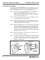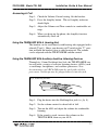
1
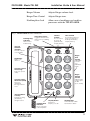
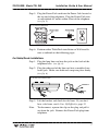
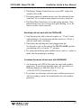
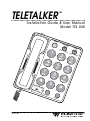
TELETALKER
™
Installation Guide & User Manual
Model TEL 040
RIN
G
VOL
UM
E
TON
E
SOF
T
LOU
D
LES
S
MO
RE
TEL
ETA
LKE ™
R
AM
PLIF
Y
RED
IAL
MAN 088D
Important Safety Information
Statements in this manual preceded by the following words are of special significance.
WARNING! Means there is the possibility of personal injury to yourself or others.
CAUTION! Means there is the possibility of damage to the equipment.
Other information of particular importance has been placed in italic type like this.
WARNING!
The TELETALKER is capable of amplifying sounds to a very loud volume. To prevent
misuse of the phone by someone who is unfamiliar with its operation and capabilities, DO
NOT remove the warning labels. Instruct all potential users in its proper operation. Do
not let children play with the TELETALKER. When the AMPLIFY function is not activated, the TELETALKER functions as a normal telephone.
WARNING!
This telephone can produce very high (loud) sound levels. Always adjust controls to minimum settings before using the phone and alert other users that hearing damage can potentially result from misuse.
WARNING!
This product can be hazardous if immersed in water. To avoid the possibility of electrical
shock, do not use it while in the bathtub or shower, or when you are wet. If you accidentally drop it into water, do not retrieve it until you have first unplugged the line cord from
the modular wall jack and the power pack from the AC wall outlet. Do not plug the telephone back in until it has dried thoroughly. Avoid using the telephone during electrical
storms in your immediate area. Urgent calls should be brief. Even though your telephone
company may be using protective measures to limit electrical surges from entering your
home, absolute protection from lighting is impossible. If you suspect a gas leak, report it
immediately. But use a telephone away from the affected area. The telephone’s electrical
contacts could create a tiny spark. While unlikely, it is possible this spark could ignite
heavy concentrations of gas.
RECYCLING INSTRUCTIONS
Battery Safety and Disposal
Help Williams Sound protect the environment! Please take the time to
dispose of your equipment properly.
Product Recycling for Customers in the European Union:
Please do NOT dispose of your Williams Sound equipment in the household trash. Please take the equipment to a electronics recycling center; OR
return the product to the factory for proper disposal.
9/13/07
TELETALKER ™ Model TEL 040
Installation Guide & User Manual
Table Of Contents
TELETALKER Enhanced Amplified Telephone System, Model TEL 040
Contents
Page
Safety Information
2
Introduction
Components
Features & Functions
4
4
4
Installation Steps
Table/Desk Installation
Wall Plate Installation
Bare Wall Installation
6
7
8
9
TELETALKER Operation
Using The Amplify Function
Making A Call
Answering A Call
Using The TELETALKER With A Hearing Aid
Using the TELETALKER with Auxiliary Devices
10
10
10
11
11
11
In Case Of Difficulty
12
FCC Notices
14
Warranty
15
Specifications
16
3
Installation Guide & User Manual
TELETALKER ™ Model TEL 040
Introduction
Congratulations on the purchase of your TELETALKER™
Enhanced Amplified Telephone System, Model TEL 040. This
state-of-the-art Williams Sound product is designed and built with
premium quality parts for your assurance of reliability.
The TELETALKER™ is designed to improve the audibility and
understandability of incoming voice signals by reducing unwanted line noise. It’s also designed to improve the clarity of the
sound signal by emphasizing higher frequency speech sounds.
The TELETALKER functions as either an amplified telephone or
as a normal telephone for users who don’t need amplification.
We suggest you read this user manual carefully to become familiar with the TELETALKER’s features and their function. The
manual explains how to install, use, and care for your new
TELETALKER.
Components
The following items are included with the TELETALKER:
• Handset
• Coiled handset cord
• Power pack
Features & Functions
Amplify Button
4
• Base
• Wall cords (2)
• User Manual
Turns Amplify and Enhance functions on
and off.
Amplify Indicator
Lights when Amplify function is on.
Tone Control
Increases high frequency sounds
(high frequency boost).
Volume Control
Increases sound volume.
Ring Indicator
Flashes when TELETALKER rings.
Redial Button
Redials last number dialed.
Pulse/Tone Switch
Selects Pulse (rotary phone systems) or
Touch-Tone Dialing.
TELETALKER ™ Model TEL 040
Installation Guide & User Manual
Ringer Volume
Adjusts Ringer volume level.
Ringer Tone Control
Adjusts Ringer tone.
Neckloop/Aux Jack
Allows use of neckloops and cochlear
processors with the TELETALKER.
Fig. 1: TELETALKER Features & Functions
Pulse/Tone Switch
Flashing Ring
Indicator
Flashes red to
indicate ring
Toggles between Pulse
and Touch-Tone dialing
modes
Special
Handset
Speaker
Volume
Control
Boosts volume
up to 25 dB
(activated by
Amplify button)
RING
VOLUME
Tone Control
Boosts high frequency
speech sounds up to
30 dB (activated by
Amplify button)
TONE
Provides superior
sound quality
SOFT
LOUD
LESS
MORE
Ringer
Tone
Control
Big Buttons
Easy to see
and use
Adjustable
to meet
your
individual
needs
Dynamic Signal
Processing
Improves speech
clarity
Ringer
Volume
Control
Dynamic Noise
Reduction (DNR)
Adjusts ringer
volume up to
95 dBA
(Hi, Lo, & Off)
Removes
unwanted
background line
noise
TELETALKER™
Anti-Feedback
Circuitry
AMPLIFY
Prevents howling
(feedback)
at high volume
Amplification
Indicator
REDIAL
Amplify Button
Redial Button
Push this to
amplify your call
Automatically redials
last number called
Glows red when
call is amplified
5
TELETALKER ™ Model TEL 040
Installation Guide & User Manual
Installation Steps
Step 1: Make sure you have a 115 VAC wall outlet and telephone jack within 6 feet of the place you’ve chosen to
install the telephone. If you have an older 4-prong jack,
you’ll need a modular jack adapter. These adapters are
available from electronic, phone, and other retail stores.
Step 2: Place the Pulse/Tone Switch, located on the side of the
phone, in either Tone or Pulse (Rotary Dial Pulse).
Make sure you choose the correct dialing mode. Tone
dialing will not work if you have only dial pulse (rotary)
service.
fig. 2: Pulse/Tone Switch
Pulse / Tone Switch
TO TEL. LINE
PULSE TONE
AC 12 V/0.85A
Switches between touch-tone
and rotary dial modes.
Step 3: Set Ringer Volume and Tone Controls to desired level.
(see fig.3)
fig. 3: Ringer Controls
OFF
HI
LO
RINGER
I
III
II
TONE
RINGER
Ringer Volume Control
Ringer Tone Control
Adjusts ringer volume (Hi, Lo, Off)
Adjusts ringer pitch (I, II, III)
Step 4: Plug the coiled handset cord into the handset. Plug the
other end into the telephone base. (see fig. 4)
fig. 4: Handset Connection
6
TELETALKER ™ Model TEL 040
Installation Guide & User Manual
Step 5: Plug the Power Pack cord into the Power Jack located at
the top end of the telephone. Plug the Power Pack into
an unswitched AC outlet within 6 feet of the telephone.
(see fig. 5)
fig. 5: Power Connection
Step 6: Perform either Table/Desk installation or Wall installation as outlined on the following pages.
For Table/Desk Installations
Step 1: Plug the long line cord into the jack on the back of the
telephone base. (see fig. 6)
Step 2: Plug the other end of the line cord into a modular baseboard jack. Make sure both ends snap into place firmly.
(see fig. 6)
fig. 6: Line Cord Connection
Step 3: Lift the handset and check for dial tone. If you don’t
hear a dial tone, see In Case Of Difficulty, page 12.
Note:
To disconnect, squeeze the clip on the plug and pull it
out from the jack. Remove the Power Pack plug from
telephone.
7
Installation Guide & User Manual
TELETALKER ™ Model TEL 040
For Wall Plate Installations
If you prefer, the TELETALKER can also be mounted on a studded wall phone plate. If you don’t have a phone plate installed,
talk to your phone company or local phone products store.
Step 1: Clip the plastic wall mounting bracket (included) into
bottom of the TELETALKER base unit. (see fig. 7)
Make sure the tabs snap in securely. This will make the
base unit level with the wall.
Step 2: Reverse the handset hanger found in the handset cradle
to prevent the handset from falling.
Step 3: Plug the short line cord into the jack on the top of the
telephone and thread the line through the channel to the
cavity on the back of the base unit.
Step 4: Hold the telephone next to the wall-phone jack and plug
the line cord into the jack, leaving any slack in the base
unit cavity. Then push the phone against the mounting
studs so the studs are hooked into the upper and lower
keyhole slots of the phone. Slide the phone down until it
snaps into place. (see fig. 7)
Step 5: Check for a dial tone. If you can’t hear a dial tone, see
In Case Of Difficulty, page 12.
Note:
To remove a wall-mounted telephone, slide the phone up
and pull it slightly away from the wall. Disconnect the
line cord by squeezing the clip on the modular plug and
pulling it from the jack.
fig. 7: Wall Installation
Short Wall Cord
Wall Mount
Bracket
Studded Wall
Phone Plate
8
TELETALKER ™ Model TEL 040
Installation Guide & User Manual
Bare Wall Installation
Even if you don’t have a studded wall phone plate, you can still
mount the TELETALKER on any wall surface within six feet of a
standard modular jack and AC outlet. To mount the phone farther
from the jack you’ll need a longer line cord or a telephone extension cord. In either case, place the AC power pack in a location
which will not be subject to disturbance.
Step 1: Measure and mark the wall for mounting screws.
Mark two points 3-1⁄4 inches apart for upper and lower
mounting screws. The lower mark should be 48–52
inches from the floor. Use a level to make sure the
marks are aligned vertically.
Step 2: Install the mounting screws (not included).
Use wood screws for stud mounting, anchor screws for
hollow wall mounting. Drive the screws almost completely in, leaving a 1⁄8 inch space between the wall surface and the bottom of the screw head (about the thickness of two stacked pennies).
Step 3: Reverse the handset hanger to prevent the handset from
falling.
Step 4: Mount the TELETALKER.
Hang the telephone on the mounting screws and push
down gently until it snaps into place
Step 5: Connect the line cord to the jack on the top of the phone.
Plug the other end of the line cord into a modular wall
jack.
Make sure it snaps firmly into place.
Step 6: Connect the AC power pack to a wall AC outlet.
Step 7: Check for the dial tone.
If you can’t hear a dial tone, see In Case Of Difficulty,
page 12.
Note:
To disconnect the telephone, squeeze the clip on the
modular plug and pull it out of the jack.
9
Installation Guide & User Manual
TELETALKER ™ Model TEL 040
TELETALKER™ Operation
Using The Amplify Function
Before amplifying a call, turn the volume and tone controls to
their minimums. To amplify a call, press the Amplify button.
This button switches amplification on and off. The red indicator
light will glow when apmlification is on. Amplification automatically turns off when you hang up the phone.
WARNING!
The TELETALKER is capable of amplifying sounds to a very loud volume.
Always set the VOLUME CONTROL to the MINIMUM setting before
using the phone. To prevent misuse of the phone by someone who is unfamiliar with its operation and capabilities, DO NOT remove warning
labels. Instruct all users in its proper operation. Do not let children play
with the TELETALKER. When the Amplify function is not activated, the
TELETALKER functions as a normal telephone.
Using The Volume Control
Turn the volume control knob clockwise to increase volume,
counter–clockwise to decrease volume.
Using The Tone Control
Turn the Tone control knob clockwise to boost high frequencies,
counter–clockwise to decrease the boost of high frequencies.
Making A Call
Step 1: Lift the handset and check the Volume Control setting.
Step 2: Press the Amplify button. The Red LED should light.
Step 3: Adjust the Volume and Tone Controls to comfortable
levels.
Step 4: When you hear a dial tone, dial the number and use as a
regular phone.
Step 5: Adjust the Volume and Tone controls for best understanding of the remote party. When you hang-up, the Amplify
function automatically turns off.
10
TELETALKER ™ Model TEL 040
Installation Guide & User Manual
Answering A Call
Step 1: Check the Volume Control setting, lift the handset.
Step 2: Press the Amplify button. The red Amplify indicator
should light.
Step 3: Adjust the Volume and Tone controls to comfortable settings.
Step 4: When you hang-up the phone, the Amplify function
automatically turns off.
Using the TELETALKER With A Hearing Aid
The handset can be used directly with hearing aids equipped with a
telecoil (T-coil ). Move your hearing aid T-switch to the “T” position and hold the handset close to your hearing aid. The volume
can be adjusted with the TELETALKER volume control.
Using the TELETALKER With Auxiliary Assistive Listening Devices
Through its 3.5mm Neckloop/Aux Jack, the TELETALKER can
be used with a variety of assistive listening devices (ALDs) such
as neckloops, headphones, and cochlear processors. Note:
An attenuator cord (WCA 040) must be used with cochlear
processors. Neckloops may be plugged directly into the jack.
fig. 8: Connecting An ALD
Step 1: Plug the device into the Neckloop/Aux jack (see fig. 8).
Step 2: Set the volume control to about half of full.
Step 3: Turn on the ALD and adjust the volume for comfortable
listening.
Step 4: If the sound is weak, increase the volume on the
TELETALKER, then on your ALD.
11
Installation Guide & User Manual
TELETALKER ™ Model TEL 040
In Case Of Difficulty
Cannot hear the other person speak. This only occurs
when the TELETALKER is in Amplify mode.
When you use the Amplify feature, the TELETALKER operates
in half-duplex mode. This means that while you speak, the handset receiver shuts off. If it did not, the extremely loud volumes
produced by the TELETALKER would cause feedback.
When using the TELETALKER in Amplify mode, do not speak
when the other party is speaking.
Can answer calls but cannot make them
The pulse/tone switch is set in the wrong position. Change it to
pulse mode.
No dial tone when you pick-up handset
There are a number of potential causes to this problem:
1. Cords on handset or phone are not plugged into jacks. Make
sure connectors are plugged in securely.
2. The cord could be damaged. If so, replace the cord.
3. The wall jack could be improperly wired. Check the wall jack
for proper wiring.
4. Your phone line could be out of order. Contact your local
phone company.
Can make calls, but phone doesn’t ring for incoming calls.
There are a number of potential causes to this problem:
1. The handset may not be placed properly on the base. Make
sure it is resting properly on the base.
12
TELETALKER ™ Model TEL 040
Installation Guide & User Manual
2. The Ringer Volume Control may be set to OFF. Adjust the
switch to LO or HI.
3. Too many phones or phone devices may be connected to the
same line. If so, remove other phones or devices from line.
4. The Pulse/Tone Switch may be in the wrong position. Your
phone line may be set to accept only pulse dialing. If so, be
sure to set this switch correctly.
Neckloop will not work with the TELETALKER.
1. Only hearing aids with a telecoil coupler (or “T-coil”) work
with neckloops. If your hearing aid does not have a T-coil, it
will not work with a neckloop.
2. Check that the neckloop has been plugged into the
Neckloop/Aux jack on the side of the TELETALKER and that
your hearing aid is set in the “T” position.
3. Try using the neckloop with another device (such as a radio) to
make sure the neckloop is working.
Cochlear Processor will not work with TELETALKER.
1. An attenuator cord (WCA 040) must be used with cochlear
processors. If you do not have this cord, call your dealer or
Williams Sound at 1-800-843-3544 (U.S.A.) or
+1 952-943-2252 (Outside the U.S.A.).
2. If you have an attenuator cord and your cochlear processor is
still not working, contact the manufacturer of your cochlear
processor.
13
Installation Guide & User Manual
TELETALKER ™ Model TEL 040
FCC Registration Notice
Your new TELETALKER product has been registered with the Federal Communications Commission (FCC). This product complies with standards in Part 68 of the FCC Rules. The FCC requires us to provide you with the following information:
1.
Connection and use with the nationwide telephone network
The FCC requires that you connect your product to the nationwide telephone network through a modular telephone
outlet or jack. The modular telephone outlet or jack to which the telephone must be connected is a USOC RJ-11C
or RJ-11W.
2.
Notification to the telephone company
The FCC requires that upon request of your local telephone company, you provide the following information:
This equipment may not be used with Party Line Service or with Coin Telephone Lines.
A.
The ‘line’ to which you will connect the telephone equipment (your phone number).
B.
The telephone equipment’s FCC registration number and Ringer Equivalence Number (REN). These numbers
are on the back or bottom of your telephone equipment.
The REN is useful to determine how many devices you may connect to your telephone line and still have
them ring when your telephone line is called. In most, but not all areas, the sum of all REN’s should be 5 or
less. You may want to contact your local telephone company if you experience problems.
3.
Repair instructions
If it is determined that your telephone equipment is malfunctioning, the FCC requires that it not be used and that it
be unplugged from the modular outlet until the problem has been corrected. Repairs to this telephone equipment
can only be made by the manufacturer or its authorized agents or by others who may be authorized by the FCC.
For repair procedures, follow the instructions under the section entitled Warranty.
4.
Rights of the telephone company
If your product is causing harm to the telephone network, the telephone company may temporarily discontinue your
telephone service. If possible, they will notify you before they interrupt service. If advance notice isn’t practical,
you’ll be notified as soon as possible. You’ll be given the opportunity to correct the problem, and you’ll be
informed of your right to file a complaint with the FCC.
Your telephone company may make changes in its facilities, equipment, operations, or procedures that could effect
the proper functioning of your TELETALKER product. If such changes are planned, you’ll be notified.
5.
This telephone is compatible with inductively coupled (Telecoil) hearing aids.
Interference Information: Part 15 Of FCC Rules
Some telephone equipment generates and uses radio-frequency energy and, if not installed properly, may cause interference to radio and television reception.
Your TELETALKER product has been tested and found to meet the standards for a Class B computing device, as specified in Subpart J of Part 15 of the FCC Rules. These specifications are designed to provide reasonable protection against
such interference in a residential installation. However, there is no guarantee that interference will not occur in a particular installation.
If your TELETALKER product causes interference to radio or television reception when it’s in use, you might correct the
interference with any one of these measures.
1.
Where it can be done safely, re-orient the receiving telephone or radio antenna.
2.
To the extent possible, relocate the television, radio or other receiver with respect to the telephone equipment.
3.
If your telephone product runs on AC power, plug your product into an AC outlet that’s not in the same circuit as
one used by your radio or television.
14
TELETALKER ™ Model TEL 040
Installation Guide & User Manual
Limited Warranty
Williams Sound products are engineered, designed, and manufactured under carefully controlled conditions to provide you with many years of reliable service. Williams Sound warrants
the TELETALKER TEL 040 against defects in materials and workmanship for FIVE (5) years.
During the first five years from the purchase date, we will promptly repair or replace the
TELETALKER TEL 040.
Microphones, earphones, headphones, batteries, cables, antennas, carry cases, and all other
accessory products carry a 90-day warranty.
WILLIAMS SOUND HAS NO CONTROL OVER THE CONDITIONS UNDER WHICH
THIS PRODUCT IS USED. WILLIAMS SOUND, THEREFORE, DISCLAIMS ALL WARRANTIES NOT SET FORTH ABOVE, BOTH EXPRESS AND IMPLIED, WITH RESPECT
TO THE TELETALKER TEL 040, INCLUDING BUT NOT LIMITED TO, ANY IMPLIED
WARRANTY OF MERCHANTABILITY OR FITNESS FOR A PARTICULAR PURPOSE.
WILLIAMS SOUND SHALL NOT BE LIABLE TO ANY PERSON OR ENTITY FOR ANY
MEDICAL EXPENSES OR ANY DIRECT, INCIDENTAL OR CONSEQUENTIAL DAMAGES CAUSED BY ANY USE, DEFECT, FAILURE OR MALFUNCTIONING OF THE
PRODUCT, WHETHER A CLAIM FOR SUCH DAMAGES IS BASED UPON WARRANTY,
CONTRACT, TORT OR OTHERWISE, THE SOLE REMEDY FOR ANY DEFECT, FAILURE OR MALFUNCTION OF THE PRODUCTS REPLACEMENT OF THE PRODUCT. NO
PERSON HAS ANY AUTHORITY TO BIND WILLIAMS SOUND TO ANY REPRESENTATION OR WARRANTY WITH RESPECT TO THE TELETALKER TEL 040. UNAUTHORIZED REPAIRS OR MODIFICATIONS WILL VOID THE WARRANTY.
The exclusions and limitations set out above are not intended to, and should not be construed
so as to contravene mandatory provisions of applicable law. If any part or term of this
Disclaimer of Warranty is held to be illegal, unenforceable, or in conflict with applicable law
by a court of competent jurisdiction, the validity of the remaining portions of this Disclaimer of
Warranty shall not be affected, and all rights and obligations shall be construed and enforced as
if this Limited Warranty did not contain the particular part or term held to be invalid.
If you experience difficulty with your system, call for customer assistance:
1-800-843-3544 (U.S.A.) or +1-952-943-2252 (Outside the U.S.A.)
If it is necessary to return the system for service, your Customer Service Representative will
give you a Return Authorization Number (RA) and shipping instruction.
Pack the system carefully and send it to:
Williams Sound Corp.
Attn: Repair Dept.
10321 West 70th Street
Eden Prairie, MN 55344 USA
Your warranty becomes effective the date you purchase your system. Your returned warranty
card is our way of knowing when your warranty begins. It also gives us important information
about your system including the serial number. This information will help us serve you better in
the future. Please take a moment to complete and mail the attached card. Thank you.
15
Installation Guide & User Manual
TELETALKER ™ Model TEL 040
SPECIFICATIONS
TELETALKER™ Amplified Telephone, Model TEL 040
Dimensions:
2.2" D, 8.9" H, 7.6" W (56mm D, 226mm H, 192mm W)
Color:
White with dark gray controls
Wide-band Gain:
25 dB maximum
High Frequency Gain:
30 dB maximum
Audio Freq. Response:
300 Hz to 2800 Hz, ± 3 dB
Max. HF Acoustic Gain:
55 dB
Sat. Acoustic Output:
130 dB SSPL
Total Harm. Distortion:
< 3% at 120 dB SPL output,
1000 Hz, Tone control at min
Signal to Noise Ratio:
51 dB, NAB Weighted
Signal Processing:
Dynamic Signal Processing
Noise Reduction:
Dynamic Noise Reduction (DNR®)*
Ringer Volume Control:
Hi, Lo, Off
Ringer Loudness:
90-95 dBA SPL at 1 meter (Hi position)
Ringer Pitch Control:
Adjustable, 3 positions (lo, med, hi)
Flasher:
Jumbo LED, high visibility, red
Neckloop/Aux. Jack:
3.5 mm mono jack,
2.7 Ω impedance, 150 mW max. output
Connections:
2-wire central office connection, modular plug
Ringer Equiv. Number (REN): 1.0B
Power:
Includes 12 VAC power supply
Approvals:
FCC, WEEE
Warranty:
Five Years, Parts and Labor**
*
**
Trademark of National Semiconductor Corp.
90 days on cords and power supply
®
10321 West 70th St., Eden Prairie, MN 55344 U.S.A.
800.843.3544 | 952.943.2252 | FAX: 952.943.2174
www.williamssound.com
© 2007, Williams Sound Corp. MAN 088D