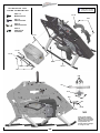
1
s
n
o
i
t
c
u
r
t
s
n
I
y
l
b
m
e
s
As
Nitro
Helicopter Kit
MA1031 Flybar
MA1031-1 Flybarless
Step up to excellence with X-Cell
Table of Contents
Kit Introduction................................................................................................................................... 3
R/C Helicopter Safety......................................................................................................................... 3
Warning....................................................................................................................................................3
General Guidelines..................................................................................................................................3
Academy of Model Aeronautics (AMA)............................................................................................ 4
Kit Assembly....................................................................................................................................... 5
Required Tools.........................................................................................................................................5
Other Required Components...................................................................................................................5
Assembly Tips.................................................................................................................................... 6
Kit Contents........................................................................................................................................ 7
Flybarless Head Assembly (Whiplash Kit #MA1031-1)..................................................................... 9
Flybarless Head Parts List.......................................................................................................................9
Flybarless Head Assembly Instructions.................................................................................................10
Flybarless Head Link Lengths................................................................................................................11
Flybar Head Parts List...........................................................................................................................12
Flybar Head Assembly Instructions........................................................................................................13
Flybar Head Link Lengths......................................................................................................................16
Tail Assembly Parts List.........................................................................................................................17
Tail Assembly Instructions......................................................................................................................18
Nitro Frame Assembly Parts List............................................................................................................23
Nitro Frame Assembly Instructions........................................................................................................24
Electronics Mounting Positions..............................................................................................................33
Canopy Mounting...................................................................................................................................33
Flybar Head Assembly (Whiplash Kit #MA1031)............................................................................. 12
Tail Assembly.................................................................................................................................... 17
Nitro Frame Assembly..................................................................................................................... 23
Basic Model/Radio Set Up............................................................................................................... 34
Swashplate eCCPM Set Up.............................................................................................................. 35
Pitch Curve Set Up........................................................................................................................... 36
Throttle Curve Set Up....................................................................................................................... 37
Flybarless Stabilization Electronics............................................................................................... 37
Kit Hardware and Parts.................................................................................................................... 38
Warranty Information....................................................................................................................... 39
2
Kit Introduction
Thank you for purchasing the X-Cell Whiplash by Miniature Aircraft USA. This model is the culmination of
years of designing and manufacturing R/C helicopters. It is designed with the highest standards, and will
provide years of enjoyment. Whether this is your first R/C model helicopter or you are an advanced R/C
helicopter modeler, the X-Cell Whiplash is a fantastic choice for a “700 size” model.
R/C Helicopter Safety
A radio controlled model helicopter is not a toy, but rather a technically complex device that must be built
and operated with care. It is also a fascinating and challenging part of the R/C sport, the mastery of which
is very rewarding. A model helicopter must be built exactly in accordance with the building instructions. The
kit manufacturer has spent much time and effort refining his product to make it reliable in operation and easy
to build. The essentially bolt together construction can proceed quite rapidly, giving the builder a strong
sense of accomplishment that encourages hasty progress from one construction phase to the next, so that
the completed model can be more quickly seen and enjoyed. It is essential to recognize and guard against
this tendency. Follow building instructions exactly. Vibration and stress levels are high and all fasteners and
attachments must be secure for safe operation.
Note that this is the first use of the word SAFETY in these comments. Previously the kit manufacturer’s efforts
to ensure reliable operation were mentioned. That is ALL that he can do. Safe operation is the responsibility
of the builder/flyer and starts with careful construction and continues with selection and installation of reliable
radio equipment and engine.
The need for safety is nowhere greater than at the flying field. A number of guidelines for safe flight have
been developed by experienced flyers and are set down here. It is urged that they be read, understood and
followed.
Warning! – Risk of death or serious injury
Remote Control (“R/C”) Helicopters can be dangerous. Inexperienced pilots of R/C Helicopters should
be trained and supervised by experienced operators. All operators should use safety glasses and other
appropriate safety equipment. All operators should exercise necessary precautions when fueling, repairing,
maintaining, flying and storing R/C Helicopters, and when using or storing R/C Helicopter accessories,
equipment, fuels, and related materials. R/C Helicopters should be used only in open areas free of obstacles
and far enough from people to minimize the possibility of injury from the helicopter or any of its components
falling or flying in unexpected directions.
This helicopter is not a toy but a complex flying machine that must be assembled with care by a responsible
individual. Failure to exert care in assembly, or radio or accessory installation, may result in a model
incapable of safe flight or ground operation. Rotating components are an ever present danger and source of
injury to operators and spectators. Since the manufacturer and his agents have no control over the proper
assembly and operation of his products, no responsibility or liability can be assumed for their use.
General Guidelines for Safe R/C Helicopter Flight
• Fly only at approved flying fields and obey field regulations.
• Follow frequency control procedures. Interference can be dangerous to all.
• Know your radio. Check all transmitter functions before each flight.
• Be aware that rotating blades are very dangerous and can cause serious injury.
• Never fly near or above spectators or other modelers.
• If you’re a beginner, get help trimming the model first and flight training later.
• Don’t “track” the main blades by holding the tail boom. This is a temptation to builders who cannot hover
yet and is very dangerous.
• Follow all recommended maintenance procedures for model, radio and engine.
3
Academy of Model Aeronautics
Miniature Aircraft USA highly recommends joining the Academy of Model Aeronautics (AMA).
• AMA is the Academy of Model Aeronautics.
• AMA is the world’s largest model aviation association, representing a membership of more than 150,000
from every walk of life, income level and age group.
• AMA is a self-supporting, non-profit organization whose purpose is to promote development of model
aviation as a recognized sport and worthwhile recreation activity.
• AMA is an organization open to anyone interested in model aviation.
• AMA is the official national body for model aviation in the United States. AMA sanctions more than a
thousand model competitions throughout the country each year and certifies official model flying records
on a national and international level.
• AMA is the organizer of the annual National Aeromodeling Championships, the world’s largest model
airplane competition.
• AMA is the chartering organization for more than 2,500 model airplane clubs across the country. AMA
offers its chartered clubs official contest sanction, insurance and assistance in getting and keeping flying
sites.
• AMA is the voice of its membership, providing liaison with the Federal Aviation Administration, the Federal
Communications Commission, and other government agencies through our national headquarters in
Muncie, Indiana. AMA also works with local governments, zoning boards and parks departments to
promote the interests of local chartered clubs.
• AMA is an associate member of the National Aeronautic Association. Through NAA, AMA is recognized by
the Fédération Aéronautique Internationale (FAI), the world governing body of all aviation activity, as the
only organization which may direct U.S. participation in international aeromodeling activities.
For more detailed information, contact the Academy of Model Aeronautics
5161 E. Memorial Drive, Muncie, Indiana, 47302
or telephone (800) 435-9262.
You may also visit the AMA website at www.modelaircraft.org
4
Kit Assembly
Your Whiplash kit will require a number of different supplies and tools to ensure the best final result. They
are as follows:
Required Lubricants and Compounds:
1. Medium Strength Thread Locking Compound - X-Cell Super Lock Blue (MA3200-20)
2. Tri-Flow Oil (MA3200-02)
3. Tri-Flow Synthetic Grease (MA3200-06)
4. Medium Cyanoacrylate (CA)
5. Retaining Compound - X-Cell Super Lock Green (MA3200-22)
Required Tools:
1. m4 Nut Driver
2. m5 Nut Driver
3. m5.5 Nut Driver
4. m7 Nut Driver
5. 1.5mm Allen Driver
6. 2.0mm Allen Driver
7. 2.5mm Allen Driver
8. 3.0mm Allen Driver
9. 4.0mmAllen Driver x2
10.5.0mm Allen Driver
11.Needle Nose Pliers
12.Phillips Screwdriver
13.Razor Knife (X-acto)
Other required components:
The X-Cell Whiplash is an airframe kit. To complete the model, several other items are required but are not
included with the kit. There are many choices for these other required components, and any competent
hobby retailer with R/C helicopter experience will be happy to make suggestions. You will need:
1.Engine, “90-120” size nitro helicopter engine.
2.Helicopter style muffler suited to the engine you choose.
3.Cyclic servos (Miniature Aircraft USA recommends high quality digital cyclic servos with no less than
80 oz. in. of torque.)
4. Throttle servo (Miniature Aircraft USA recommends a high quality ball bearing sevro)
4.R/C helicopter gyro (Miniature Aircraft USA recommends for Flybarless Kits a flybarless electronic
unit with rudder gyro and for Flybar Kits only a tail “heading hold” style gyro is needed)
5. Rudder servo suitable for use with the gyro you choose. Digital servo is recommended.
6. R/C helicopter transmitter and receiver with at least 6 channels, and eCCPM capabilities.
7. 690-710mm Main Blades and 105mm Tail Blades
8. R/C helicopter starting and fueling equipment
9. R/C helicopter engine governor is recommended
5
Important Assembly Tips - Please Read
• Follow the instructions. The methods of construction documented in this manual have been proven to
work. Do not rush the build of your model! You have purchased a world class model helicopter kit, take
your time and realize that the final result is now up to you. Take the time to fully understand each step and
if you are unsure please contact Miniature Aircraft USA.
• Follow the order of assembly. The instructions have been organized into major sections and have been
written in such a way that each step builds upon the work done in the previous step. Changing the order of
assembly may result in unnecessary steps.
• Clean all metal parts. All of the steel parts in this kit are coated with a lubricant to prevent them from
rusting. This coating can interfere with the adhesives and thread locks needed for assembly. Use a solvent
such as alcohol or acetone to clean the various metal parts, especially threads. Be sure not to overtighten
bolts as damage to bearings and other components will occur.
• It is very important to lightly sand the edges of all carbon fiber pieces. Miniature Aircraft USA recommends
doing so prior to the assembly process. Carbon fiber edges are sharp and can easily cut component wires
and battery mounting straps. It is important to use safety precautions when creating carbon fiber dust.
The use of a particulate mask, preferably one with a P100 HEPA filter is recommended. Always clean up
carbon fiber dust with a damp rag right away.
• Use thread lock as indicated. Generally any bolt or screw that threads into a metal part requires thread
lock. Model helicopters are subject to vibration and failing to use thread lock on any non-locking assembly
may result in a part becoming loose or falling off.
6
Kit Contents
Please take some time to familiarize yourself with the contents of the kit. The Whiplash kit has been broken down into
three “bags”. Each bag contains parts and hardware. The hardware for each bag will be used only for that bag. There
will be no left over parts after each bag is assembled. The individual parts of the factory assembled parts are not listed
out here. They can be found in the components section of the manual.
Bag 1 - Flybarless Kits (MA1031-1)
Bag
Part No. Part Description
Qty
Bag
1-A
1-A
1-A
1-A
1-A
1-A
1-A
0869
128-176
128-195
128-314
131-187
131-190
131-368
2
2
1
2
1
2
1
1-Hardware 0021
M4 Lock Nut
1
1-Hardware 0023
M5 Nut
2
1-Hardware 0051
M3x3 Set Screw
3
1-Hardware 0061
M3x8 Socket Bolt
4
1-Hardware 0063
M3x10 Socket Bolt
2
1-Hardware 0064-4 M3x16 Button Head Socket Bolt
2
1-Hardware 0067
M3x14 Socket Bolt
1
1-Hardware 0082-4 M5x32 Shouldered Socket Bolt
2
1-Hardware 0086-1 M5x16 Flanged Socket Bolt
2
1-Hardware 0107
M3x6 Threaded Steel Ball
5
1-Hardware 0109
M3x8 Threaded Steel Ball
4
1-Hardware 0447-1 M2 E-clip
2
1-Hardware 120-7
5x15 C/F Safety Washer
2
1-Hardware 131-83 Anti-rotation Pin
1
1-Hardware 131-184 C/F Damper Washer
2
1-Hardware 131-200 M4x33 Shouldered Socket Bolt
1
Washout Link
Washout Pin
Head Button
Swashplate Follower
Head Axle
Damper (80D)
FBL Head Block
1-B
0133-1 M3x21.5 Ball Link
10
1-B
0217
Swashplate
1
1-B
121-4
Servo To Swash Linkage Rod
3
1-B
121-7
Swash To PA Linkage Rod
2
1-B
131-308 FBL Main Shaft
1
1-C
131-161 Main Blade Grip
2
1-C
131-163 FBL Pitch Arm
2
Part No. Part Description
Qty
Bag 1 - Flybar Kits (MA1031)
Bag
Part No. Part Description
1-A
0133-1 M3x21.2 Ball Link
1-A
121-4
Servo To Swash Rod
1-A
128-189 Cage Bar
1-A
128-195 Head Button
1-A
131-155 Cage End
1-A
131-168 FB Head Block
1-A
131-187 Head Axle
1-A
131-190 Damper (80D)
1-B
120-7
5x15 C/F Safety Washer
1-B
128-196 Alumimum Bell Mixer
1-B
131-161 Main Blade Grip
1-B
131-162 FB Pitch Arm
1-B
131-184 9x14x.080 C/F Damper Washer
1-C
0217
Swashplate
1-C
0219
Washout Center Hub
1-C
0869
Washout Link
1-C
106-05 Washout Arm
1-C
128-176 Washout Pin
1-C
131-8
FB Main Shaft
1-D
0133
M2x21.2 Ball Link
1-D
0133-1 M3x21.2 Ball Link
1-D
0135
M2x16.4 Ball Link
Qty
Bag
4
2
2
1
2
1
1
2
1-D
0313
M2x10 Threaded Control Rod
1-D
120-25 Swash To Mixer Linkage Rod
1-D
121-4
Servo To Swash Linkage Rod
BOX
0303
Flybar
1-Hardware 0021
M4 Lock Nut
1-Hardware 0023
M5 Nut
1-Hardware 0050-1 M2.5 Set Screw
1-Hardware 0051
M3x3 Set Screw
1-Hardware 0057
M4x4 Set Screw
1-Hardware 0061
M3x8 Socket Bolt
1-Hardware 0063
M3x10 Socket Bolt
1-Hardware 0064-3 M3x6 Button Head Socket Bolt
1-Hardware 0067
M3x14 Socket Bolt
1-Hardware 0071
M3x18 Socket Bolt
1-Hardware 0082-4 M5x32 Shouldered Socket Bolt
1-Hardware 0086-1 M5x16 Flanged Socket Bolt
1-Hardware 0107
M3x6 Threaded Steel Ball
1-Hardware 0109
M3x8 Threaded Steel Ball
1-Hardware 0112
M3x9.5 Threaded Steel Ball
1-Hardware 0447-1 M2 E Clip
1-Hardware 131-83 Anti Rotation Pin
1-Hardware 131-200 M4x33 Shouldered Socket Bolt
2
2
2
2
2
1
1
2
2
2
1
2
10
2
7
Part No. Part Description
Qty
2
2
3
1
1
2
2
3
2
4
2
4
3
2
2
2
5
6
4
2
1
1
Bag 2 - Tail Assembly
Bag
Part No. Part Description
2-A
0133
M2x21.2 Ball Link
2-A
128-144 T/R Control Rod Guide
2-A
131-57 Torque Tube Ends
2-A
131-58 Torque Tube
2-A
131-62 Tail Boom
2-A
131-69-1 T/R Control Rod
2-A
131-80 Torque Tube Bearing Cup
2-A
131-81 Torque Tube Bearing Cup O-ring
2-A
131-86 Assembled Boom Support
2-B
131-34 Front Tail Transmission
2-B
131-35 Boom Clamp W/TX Holes
2-B
131-64 T/R Hub
2-B
131-75 T/R Pitch Slider Assembly
2-B
131-112 T/R Blade Grip
2-B
131-129 Tail Box
2-B
131-130 Tail Pitch Control Bellcrank
2-B
131-131 C/F Bellcrank Bracket
2-B
131-132 Bellcrank Slider Cup
Bag
Qty
Bag
2
4
2
1
1
1
2
4
2
2-C
128-80 Front Boom Clamp
1
2-C
128-149a Upper Rear Boom Support Mount
1
2-C
128-149b Lower Rear Boom Support Mount
1
2-C
131-60 C/F Tail Fin
1
2-C
131-128 C/F Boom Clamp Plate
1
2-Hardware 0009
M3 Washer
2
2-Hardware 0016-1 M4 External Serrated Lock Washer
2
2-Hardware 0019
M3 Lock Nut
2
2-Hardware 0056
M3x5 Dog-Point Set Screw
2
2-Hardware 0059-0 M2.5x4 Socket Bolt
6
2-Hardware 0059-1 M2.5x6 Socket Bolt
1
2-Hardware 0060-1 M3x6 Socket Bolt
4
2-Hardware 0061
M3x8 Socket Bolt
3
2-Hardware 0064-3 M3x6 Button Head Socket Bolt
2
2-Hardware 0065
M3x12 Socket Bolt
6
2-Hardware 0067
M3x14 Socket Bolt
2
2-Hardware 0069
M3x16 Socket Bolt
3
2-Hardware 0078
M4x12 Socket Bolt
2
2-Hardware 0107
M3x6 Threaded Steel Ball
4
1
1
1
1
2
1
1
1
1
0133
0133-1
0390
106-22
122-94
128-59
131-1
131-69
131-85
131-133
Qty
Bag 3 - Nitro Frame Assembly
Part No. Part Description
Bag
Qty
M2x21.2 Ball Link
M3x21.2 Ball Link
Wire Retainers
M5x11 Grommet
M3x97 Threaded Control Rod
M4 Frame Spacer
124T Main Gear
M2x315 Linkage Rod
C/F Pushrod Sleeve
Fan Shroud - Left
2
2
3
4
1
1
1
1
1
1
Part No. Part Description
3-D
131-134 Fan Shroud - Right
3-D
131-136 Struts
3-D
131-139 Skids
3-D
131-24 Main Gear Hub
3-D
131-50 Elevator Servo Mount
3-D
131-150 Front Canopy Post
3-D
131-151 Rear Canopy Post
3-D
131-154 Thumb Screw
3-D
3200-48 3/4” Hook & Loop Tape
3-E
115-65 High Flex Fuel Line
3-E
128-92 Fuel Tank Plug
3-E
128-94 Fuel Nipple
3-E
131-138 Whiplash Nitro Fuel Tank
3-E
131-144 Rubber Fuel Tank Mount
3-E
131-145 Fuel Tank Standoff
3-E
3400-70 Fuel Pick-Up Magnet
3-Hardware 0004
M4 Washer
3-Hardware 0009
M3 Washer - Small
3-Hardware 0011-4 M5x15x.08 Washer
3-Hardware 0014F
5mm Hex Nut
3-Hardware 0016-1 M4 External Serrated Lock Washer
3-Hardware 0017-2 M2.5 Hex Nut
3-Hardware 0021
M4 Lock Nut
3-Hardware 0032
M3 Self Tapping Screw
3-Hardware 0053-5 M3x16 Set Screw
3-Hardware 0057
M4x4 Set Screw
3-Hardware 0059-1 M2.5x6 Socket Bolt
3-Hardware 0059-3 M2.5x10 Socket bolt
3-Hardware 0060-1 M3x6 Socket Bolt
3-Hardware 0061
M3x8 Socket Bolt
3-Hardware 0063
M3x10 Socket Bolt
3-Hardware 0064-3 M3x6 Button Head
3-Hardware 0065
M3x12 Socket Bolt
3-Hardware 0069
M3x16 Socket Bolt
3-Hardware 0078-3 M4x6 Socket Bolt
3-Hardware 0081
M4x16 Socket Bolt
3-Hardware 0088
M3x8 Tapered Socket Bolt
3-Hardware 0107
M3x6 Threaded Steel Ball
3-Hardware 0116
M2.5 Threaded Steel Ball
3-Hardware 131-201 M4x25 Shouldered Socket Bolt
3-A
131-87 C/F Right Frame - Nitro
1
3-A 131-88 C/F Left Frame - Nitro
1
3-A 131-29 C/F X Brace
1
3-A 131-47 C/F Servo Rail Spacer
2
3-A 131-53 C/F Gyro Plate
1
3-A 131-55 C/F Angled Battery Tray
1
3-A 131-115 C/F Bottom Plate - Nitro
1
3-A 131-137 C/F Rear Doubler - Nitro
2
3-A 131-146 C/F Fuel Tank Plate
1
3-A 131-148 C/F Servo Plates
14
3-A 131-153 C/F Canopy Breakaway Tabs
4
3-A 131-186 C/F Anti-rotation Bracket
1
3-A 132-59 C/F Front Doubler
2
3-B
128-57 Tray Mount
3
3-B
128-58 Frame Spacer
7
3-B
131-20 Mid Main Bearing Block
1
3-B
131-21 Upper Main Bearing Block
1
3-B
131-40 Lower Main Bearing Block
1
3-B
131-46 P/A Servo Rail
2
3-B
131-52 Delrin Tray Mount
2
3-B
131-54 M4 Tray Mount
2
3-B
131-107 T/R Bellcrank Swing Arm
1
3-B
131-109 Swing Arm Pivot
1
3-B
131-144 Rubber Fuel Tank Mount
2
3-C
128-118 6mm Hex Adaptor
1
3-C
131-3
Start Shaft
1
3-C
131-5
15T Pinion
1
3-C
131-9
Assembled Nitro Clutch Bell
1
3-C
131-117 Nitro Fan Hub
1
3-C
131-119 Nitro Clutch w/Torrington
1
3-C
131-120 Nitro Fan
1
3-C
131-122 Left Motor Mount
1
3-C
131-123 Right Motor Mount
1
3-C
131-179 Nitro X-Block
1
3-D
3-D
3-D
3-D
3-D
3-D
3-D
3-D
3-D
3-D
Part No. Part Description
BOX
BOX
BOX
8
131-152 Whiplash Canopy
131-230 Whiplash Nitro Instruction Manual
3000-73 MA Towel
Qty
1
4
2
1
2
2
2
4
15”
26”
1
1
1
2
2
1
5
8
1
1
2
6
1
8
2
6
4
20
22
60
14
10
4
1
2
10
5
2
6
1
1
1
1
MA1031-1 - Flybarless Head Assembly Parts
0021
M4 Hex Locknut
0023
M5 Hex Locknut
0051
M3x3 Socket Set
Screw
0061
M3x8 Socket Bolt
0063
M3x10 Socket Bolt
0064-4
M3x16 Button Head
Socket Bolt
0067
M3x14 Socket Bolt
0082-4
M5x32 Shouldered
Socket Bolt
0086-1
M5x16 Flanged Bolt
0107
M3x6 Threaded Steel
Ball
0109
M3x8 Threaded Steel
Ball
0133-1
M3x21.2 Ball Link
0159
3x7x3 Bearing
0217
Swashplate
0447-1
E-Clip
0597-4
M3x4.75x.215 Brass
Spacer
0869
3D Washout Link
120-7
M5x15 Carbon Fiber
Safety Washer
121-4
M3x30 Threaded
Control Rod
121-7
M3x65 Threaded
Control Rod
128-176
M2x.584 Washout
Pivot Pin
128-195
Aluminum Head Button
128-314
Swashplate Follower
131-83
Swashplate Pin
131-161
Aluminum Blade Grip
131-163
Aluminum Pitch Arm
131-184
Carbon Fiber Damper
Washer
131-187
Head Axle
131-190
Damper (80D)
131-182
9x17x5 Thrust Bearing
131-308
Flybarless Main Shaft
Apply a small amount of
medium thread lock when
threading into metal parts
0109
0109
0051
131-183
9x14x.75 Washer
131-368
Flybarless Head Block
0051
Hardware for
this assembly
0051 x 3
M3x3 Socket Set
Screw
0107 x 3
M3x6 Threaded
Steel Ball
0109 x 4
M3x8 Threaded Steel
Ball
131-83 x 1
Swashplate Pin
131-200
M4x33 Shouldered
Socket Bolt
131-181
9x17x5 Bearing
0107
0107
0217
Assembly Tip
0109
• Install MA0051 M3x3 Socket Set
Screws only until they bottom out
against the lower bearing. Do not
overtighten or damage to swashplate
bearing will occur. Note: these are
used to adjust the bearing tolerance if
it develops play over time.
131-83
9
0107
0109
0067
Hardware for
this assembly
128-195
131-190
0064-4 x 2
M3x16 Button Head
Socket Bolt
131-190
0067 x 1
M3x14 Socket Bolt
Apply
grease to
Head Axle
131-187
0447-1 x 2
E-clip
128-176 x 2
M2x.584 Washout
Pivot Pin
131-368
128-176
0869
X2
Assembly Tip
• The use of a light grease such as
MA3200-06 Tri-Flow Synthetic Grease
is required for damper/head axle
lubrication
0447-1
0159
0597-4
128-314
0159
Factory Installed
0064-4
Apply a small amount of
medium thread lock when
threading into metal parts
Hardware for
this assembly
0107 x 2
M3x6 Threaded
Steel Ball
0061 x 4
M3x8 Socket Head
Cap Screw
131-161
X2
0086-1 x 2
M5x16 Flanged Bolt
120-7 x 2
M5x15 Carbon Fiber
Safety Washer
131-183 x 2
9x14x.75 Washer
0107
131-163
0061
131-184 x 2
Carbon Fiber Damper
Washer
131-184
131-181
Bearings Factory Installed
in Blade Grips
Assembly Tips
131-182
•T
he use of a light grease
such as MA3200-06 Tri-Flow
Synthetic Grease is required
for thrust bearing lubrication
(pre-applied and assembled
from factory)
•3
piece thrust bearing
(MA131-182) outer race with
larger I.D. (inside diameter)
installs closest to hub.
Large
I.D.
10
Small
I.D.
131-183
131-181
0086-1
120-7
Hardware for
this assembly
0082-4
0021 x 1
M4 Hex Locknut
0023 x 2
M5 Hex Locknut
0063 x 2
M3x10 Socket Bolt
0082-4 x 2
M5x32 Shouldered
Socket Bolt
0023
0063
131-200
131-200 x 1
M4x33 Shouldered
Socket Bolt
0021
0023
0063
131-308
Apply a small amount of
medium thread lock when
threading into metal parts
Link Arm
Lengths and
Installation
X2
47.5mm
0133-1
X3
0133-1
121-7
13.5mm
121-4
0133-1
0133-1
11
MA1031 - Flybar Head Assembly Parts
0063
M3x10 Socket Bolt
0021
M4 Hex Locknut
0023
M5 Hex Locknut
0050-1
M2.5x3 Socket Set
Screw
0051
M3x3 Socket Set
Screw
0057
M4x4 Socket Set
Screw
0061
M3x8 Socket Bolt
0064-3
M3x6 Button Head
Socket Bolt
0067
M3x14 Socket Bolt
0071
M3x18 Socket Bolt
0078-3
M4x6 Socket Bolt
0082-4
M5x32 Shouldered
Socket Bolt
0086-1
M5x16 Flanged Bolt
0107
M3x6 Threaded Steel Ball
0133
M2x21.2 Plastic
Ball Link
0133-1
M3x21.2 Plastic
Ball Link
0135
M2x16.4 Plastic
Ball Link
0159
3x7x3 Bearing
0217
Swashplate
0109
0112
M3x8 Threaded Steel Ball M3x9.5 Threaded Steel
Ball
0219
Washout Center Hub
0283
6x10x3 Flanged Bearing
0303
M4x17.75” Flybar
0313
M2x10 Threaded
Control Rod
0447-1
E-clip
0840-27
Washout Head Pin
0869
3D Washout Link
106-02
3x7x3 Flanged Bearing
106-05
Aluminum Washout Arm
106-06
2x5x.5 Flanged Bearing
120-7
M5x15 Carbon Fiber
Safety Washer
120-25
M2.6x86 Threaded
Control Rod
121-4
M3x30 Threaded Control
Rod
122-28
M3x.125”x.79” Brass
Spacer
128-176
M2x.584 Washout Pivot
Pin
128-189
Flybar Control Bar
128-196
Aluminum Bell Mixer
128-195
Aluminum Head Button
131-8
Flybar Main Shaft
131-83
Swashplate Pin
131-155
Flybar Cage End
131-157
Flybar Cross Tube
131-161
Aluminum Blade Grip
131-162
Flybar Pitch Arm
131-166
4x8x3 Flanged Bearing
131-168
Flybar Head Block
131-183
9x14x.75 Washer
131-184
Carbon Fiber Damper
Washer
131-187
Head Axle
131-190
Damper (80D)
131-200
M4x33 Shouldered
Socket Bolt
12
131-181
9x17x5 Bearing
131-182
9x17x5 Thrust Bearing
Hardware for
this assembly
0051 x 3
M3x3 Socket Set
Screw
0107 x 3
M3x6 Threaded
Steel Ball
0109 x 2
M3x8 Threaded Steel
Ball
0112 x 2
M3x9.5 Threaded
Steel Ball
131-83 x 1
Swashplate Pin
0051
0112
0109
0051
0107
0107
0217
Assembly Tip
0112
• Install MA0051 M3x3 Socket Set
Screws only until they bottom out
against the lower bearing. Do not
overtighten or damage to swashplate
bearing will occur. Note: these are
used to adjust the bearing tolerance if
it develops play over time.
131-83
0107
Hardware for
this assembly
106-05
0109
Apply a small amount of
medium thread lock when
threading into metal parts
0109
0071 x 2
M3x18 Socket Bolt
0109 x 2
M3x8 Threaded Steel
Ball
0159
Factory Installed
122-28
0447-1 x 2
E-clip
106-02
128-176 x 2
M2x.584 Washout
Pivot Pin
0219
0071
• Do not overtighten MA0071 Socket
Bolt into plastic Washout Center Hub.
128-176
0447-1
•A
pply a very small amount of thick
cyanoacrylate glue to the inside of
the bolt holes in the washout hub
using a toothpick.
0869
Hardware for
this assembly
0109
0050-1 x 2
M2.5x3 Socket Set
Screw
Factory
Installed
0061 x 4
M3x8 Socket Bolt
106-02
0050-1
(Install last)
131-162
106-02
0109 x 2
M3x8 Threaded Steel
Ball
122-28
0067
0107
128-196
0061
0061
13
Apply a small amount of
medium thread lock when
threading into metal parts
131-161
0067 x 2
M3x14 Socket Bolt
0107 x 2
M3x6 Threaded
Steel Ball
X2
106-06
(factory installed)
Assembly Tip
X2
0067
Hardware for
this assembly
131-190
128-195
0067 x 1
M3x14 Socket Bolt
131-168
0078-3 x 2
M4x6 Socket Bolt
131-190
0112 x 2
M3x9.5 Threaded
Steel Ball
Apply grease
to Head Axle
131-166
0078-3
0112
131-187
131-166
0283
131-157
0283
Assembly Tip
• The use of a light grease such as
MA3200-06 Tri-Flow Synthetic Grease
is required for damper/head axle
lubrication
0078-3
0112
Bearings and Cross
Tube Factory Installed
into Head Block
0840-27
(factory installed)
Apply a small amount of
medium thread lock when
threading into metal parts
Hardware for
this assembly
17.5mm
X2
0064-3 x 4
M3x6 Button Head
Socket Bolt
131-155
0064-3
128-189
131-155
0133-1
128-189
121-4
0064-3
0133-1
14
X2
Bearings Factory Installed
in Blade Grips
131-184
131-181
131-182
131-183
131-181
Large
I.D. Small
I.D.
Hardware for
this assembly
120-7
0086-1
0057
0021 x 1
M4 Hex Locknut
0057 x 2
M4x4 Socket Set
Screw
0021
0063 x 2
M3x10 Socket Bolt
0067 x 2
M5x16 Flanged Bolt
120-7 x 2
M5x15 Carbon Fiber
Safety Washer
131-184 x 2
Carbon Fiber Damper
Washer
0063
0303
131-200
0063
131-183 x 2
9x14x.75 Washer
Washout Links install
onto longer MA0112
Threaded Steel Balls
131-200 x 1
M4x33 Shouldered
Socket Bolt
Assembly Tips
• The use of a light grease such
as MA3200-06 Tri-Flow Synthetic
Grease is required for thrust
bearing lubrication (pre-applied and
assembled from factory)
131-8
•3
piece thrust bearing (MA131-66)
outer race with larger I.D. (inside
diameter) installs closest to hub.
•E
nsure equal lengths of MA0303
Flybar extended out of the flybar
control assembly.
15
Hardware for
this assembly
0082-4
0023 x 2
M5 Hex Locknut
0082-4 x 2
M5x32 Shouldered
Socket Bolt
0023
0133
0023
0313
0135
0133-1
0133-1
120-25
121-4
0133-1
0133-1
72.5mm
X2
19mm
32mm
X3
X2
16
Tail Assembly Parts
0051
M3x3 Socket Set
Screw
0056
M3x5 Dog Point
Socket Screw
0058-3
M4x16 Socket Set
Screw
0059-0
M2.5x4 Socket Bolt
0064-3
M3x6 Button Head
Socket Bolt
0065
M3x12 Socket Bolt
0067
M3x14 Socket Bolt
0069
M3x16 Socket Bolt
0078
M4x12 Socket Bolt
0159
3x7x3 Bearing
0215
Auto Hub Ret. Collar
0225
Pivot Pin For
Pitch Links
0273
M6x10x.011” Steel
Shim Waasher
0319
8x16x5 Bearing
0442
Pivoting T/R Pitch
Link
120-39
5x10x4 Bearing
122-70
M.5x.25 Shim
127-86
M6x9.7x1.0 Shim
Washer
128-80
Aluminum Front
Boom Clamp
128-144
T/R Control Rod
Guides
128-149
Rear Boom Support
Mount
128-146
Aluminum Boom
Support Ends
131-15
Tail Drive Gear
131-17
Tail Bevel Gear,
Shaft Side
131-18
Tail Bevel Gear,
Torque Tube Side
131-23
6x13x5 Bearing
131-33
15x21x4 Bearing
131-34
Front Tail Drive
Transmission
131-35 Boom Clamp
w/Transmission Holes
131-51
Jack Shaft
131-57
Torque Tube End
131-58
Torque Tube
131-64
Tail Hub
131-66
5x10 Thrust Bearing
131-69-1
Tail Linkage Rod
131-70
Tail Rotor Output
Shaft
131-71
Tail Pitch Yoke
131-72
Brass Slider
131-84
Carbon Boom
Support Rod
131-86
Tail Boom Support
Assembly
0009
3mm Flat Steel
Washer
0012-2
M3 Pem Nut
0059-1
M2.5x6 Socket Bolt
0060-1
M3x6 Socket Bolt
0061
M3x8 Socket Bolt
0107
M3x6 Threaded
Steel Ball
0133
M2x21.2 Ball Links
0597-1
3x4.75x.126 Brass
Spacer
131-112
T/R Blade Grip
0016-1
0019
4mm External
3mm Hex Locknut
Serrated Lockwasher
131-60
131-62
Carbon Fiber Vertical Aluminum Tail Boom
Tail Fin
131-73
7x11x3 Bearing
131-128
Carbon Fiber Boom
Clamp Plate
131-129
Tail Case
131-74
Pitch Slider Ring
131-80
131-81
Torque Tube Bearing Torque Tube Bearing
Cup
Cup O-ring
131-130
Tail Bellcrank
17
131-131
Carbon Fiber Bellcrank
Bracket
131-132
Bellcrank Cup
131-135
Bracket Washer
0442
Hardware for
this assembly
0225
0225
0107 x 1
M3x6 Threaded
Steel Ball
0225 x 2
Pivot Pin for Washout
Arm
131-71
Factory
Assembled
131-74
131-73
0107
(not factory installed)
131-72
Hardware for
this assembly
Apply a small amount of
medium thread lock when
threading into metal parts
Factory Assembled
0051 x 2
M3x3 Socket Set
Screw
0056 x 2
M3x5 Dog Point
Socket Screw
0273 x 1
m6x10x.11” Steel
Shim Washer
131-129
131-23
131-33
Factory Assembled
131-70
131-18
0051
0056
Assembly Tip
• Make sure to include MA0273 Shim
Washer between MA131-17 Output
Gear and transmission case bearing.
0215
18
0273
131-17
0056
Hardware for
this assembly
0069
0059-1 x 2
M2.5x6 Socket Bolt
0064-3 x 2
M3x6 Button Head
Socket Bolt
0069 x 1
M3x16 Socket Bolt
0159
131-130
Factory
Assembled
0107
0064-3
131-132
(This part is not
factory installed)
0597-1
0159
0059-1
0107 x 1
M3x6 Threaded
Steel Ball
131-135
131-131
0012-2
Factory
Assembled
Assembly Tip
• The use of a light oil such as
MA3200-02 Tri-Flow Oil is required
for tail rotor output shaft/pitch
slider lubrication
Apply oil to
output shaft
Apply a small amount of
medium thread lock when
threading into metal parts
Hardware for
this assembly
X2
0009 x 2
3mm Flat Steel Washer
0019
Large
I.D.
0019 x 2
3mm Hex Nut
131-112
0061 x 2
M3x8 Socket Bolt
0069 x 2
M3x16 Socket Bolt
0061
Small
I.D.
0009
120-39
122-70
131-66
0069
0107
0107 x 2
M3x6 Threaded
Steel Ball
120-39
122-70 x 2
M.5x.25 Shim
Assembly Tips
131-64
• 3 piece thrust bearing (MA131-66)
outer race with larger I.D. (inside
diameter) installs closest to hub.
•G
rease the center ball cage of the
thrust bearing. We recommend using
MA3200-06 Tri-Flow synthetic grease.
•O
nly hand tighten MA0061 Socket
Bolt until it is moderately tight. Do
not overtighten bolt or it may result in
fatigue to bolt. Use green thread lock
on these bolts.
19
Bearings
Factory Installed
in Blade Grips
Hardware for
this assembly
0056 x 2
M3x5 Dog Point
Socket Screw
0056
0056
Assembly Tip
• Ensure the dog point tip is seated
into the dimples on the tail rotor
shaft.
Hardware for
this assembly
Apply a small amount of
medium thread lock when
threading into metal parts
131-35
0056 x 4
M3x5 Dog Point
Socket Screw
0065
131-18
0065 x 3
M3x12 Socket Bolt
0273 x 1
M6x10x.011” Steel
Shim Washer
127-86 x 1
M6x9.7x1.0 Shim
Washer
0065
Factory Assembled
127-86
0056
131-15
131-33
0056
131-23
0056
131-17
0273
131-34
131-51
20
0319
Hardware for
this assembly
131-80
131-81
0059-0 x 6
M2.5x4 Socket Bolt
Bearings
Factory Installed
in Bearing Cup
X2
NOTE: Install both bearing cup
assemblies facing the same
direction on torque tube.
0059-0
X2
131-58
131-57
0059-0
250mm
265mm
NOTE: Carefully CA glue bearing assemblies to torque tube making sure bearing locations are NOT equal
distances from torque tub ends. Use only a very small amount of thin to medium CA ensuring no CA seeps
into the bearing. Allow CA glue to dry before installing into tail boom.
Apply a small amount of
medium thread lock when
threading into metal parts
Hardware for
this assembly
0060-1
0060-1 x 3
M3x6 Socket Bolt
0067 x 2
M3x14 Socket Bolt
0060-1
End of the boom with the
3mm hole 1mm from the
end of the boom
Assembly Tips
131-128
• Ensure that the boom is full inserted
through boom clamps.
•D
o not overtighten MA0067 Socket
Bolts as it is possible to crush tail
boom.
0067
0067
131-62
128-80
21
Assembly Tips
• Use some light oil such as Tri-Flow
into tail boom to ease installation for
torque tube assembly.
• Install the torque tube with the open
ends of the bearing cups towards the
back of the tail boom assembly. This
will ensure the bearing stays seated
in the bearing cup.
•P
ush Torque Tube all the way into
Torque Tube Gear, then back out
1/16” (1.5mm) so Torque Tube and
gear can “float”.
• Install MA128-144 T/R Control Rod
Guides with the dimples towards
front of tail assembly. Use a small
amount of cyanoacrylate
glue to ensure each
guide stays in
position.
0133
128-144
131-69-1
0133
Apply a small amount of
medium thread lock when
threading into metal parts
Hardware for
this assembly
105mm Tail Rotor Blades
(not included)
0016-1 x 2
4mm External Serrated
Lockwasher
0060-1 x 1
M3x6 Socket Bolt
0061 x 1
M3x8 Socket Bolt
0061
0060-1
0065 x 3
M3x12 Socket Bolt
0065
0078 x 2
M4x12 Socket Bolt
0065
128-149
Assembly Tips
0016-1
•T
he use of “green” thread lock such
as MA3200-22 is recommended on
MA0078 Socket Bolts.
0078
131-86
(Factory Assembled includes MA0058-3,
MA128-146 & MA131-84)
•D
o not overtighten MA0065 Socket
Bolts on the Rear Boom Support
Mounts.
•A
luminum boom support ends have
a dimple on one side. The dimple
indicates a slight angle built in to this
part. On the Boom support assembly
side that attaches to the main frame,
the dimple will be facing “in”.
22
131-60
Nitro Frame Assembly Parts
0004
M4 Washer
0009
3mm Flat Steel
Washer
0011-4
5x15x.08
Washer
0059-1
M2.5x6 Socket
Bolt
0059-3
M2.5x10
Socket Bolt
0060-1
M3x6 Socket
Bolt
0116
M2.5 Threaded
Steel Ball
0133
M2x21.2 Ball
Link
0133-1
M3x21.2 Plastic
Ball Link
0012-1
0012-2
2.5mm Pem Nut 3mm Pem Nut
0061
M3x8 Socket
Bolt
0014F
5mm Hex Nut
Fine Thread
115-65
High-Flex
Fuel Line
131-55
C/F Angled
Battery Tray
131-69
M2x315
Linkage Rod
131-85
Carbon Tube
131-87
Whiplash C/F
Frame
Right - Nitro
131-119
Clutch w/Torrington
Bearing
131-120
Engine Fan
131-122
Left Motor Mount
131-123
Right Motor
Mount
131-133
Left Fan
Shroud
131-144
Rubber Fuel
Tank Mount
131-145
Fuel Tank Standoff
131-50
Elevator Servo
Mount
131-52
Delrin Tray Mount
131-53
C/F Gyro Plate
131-54
M4 Tray Mount
131-88
Whiplash C/F
Frame
Left - Nitro
131-107
Swing Arm
131-109
Swing Arm Pivot
Mount
131-115
C/F Bottom
Plate - Nitro
131-117
Fan Hub
131-134
Right Fan
Shroud
131-136
Landing Strut
131-137
C/F Rear Frame
Doubler - Nitro
131-138
Whiplash Nitro
Fuel Tank
131-139
Skid Tube
131-179
X-Block - Nitro
105-70
106-22
6x15x6 Bearing Rubber Canopy
Grommets
0107
M3x6 Threaded
Steel Ball
131-40
Bottom Main Shaft
Bearing Block
131-47
Carbon Fiber
Servo Rail Spacer
131-154
Thumb Screw
0866-8
14x22 Sprag
Bearing
0088
M3x8 Tapered
Socket Bolt
131-29
Carbon Fiber
X-brace
131-46
Pitch/Aileron
Servo Rail
131-153
Carbon Fiber
Breakaway Tab
0081
0078-3
M4x6 Socket M4x16 Socket
Bolt
Bolt
0057
0053-5
M3x16 Socket M4x4 Set Screw
Set Screw
131-24
Main Gear Hub
128-59
Front Boom
Support Spacer
131-19
10x26x8
Bearing
0032
M3 Self
Tapping Screw
131-1
124T Main Gear
131-5
15 Tooth
Pinion Gear
131-152
Whiplash Canopy
0597-1
3x4.75x.126
Brass Spacer
0021
M4 Hex
Locknut
128-118
6mm Hex
Starting Adaptor
131-3
Start Shaft
131-10
Clutch Liner
128-58
Main Frame
Spacer
0069
M3x16 Socket
Bolt
0390
Large Wire
Lead Retainer
122-48
22mm C-clip
131-151
Rear Canopy
Post
128-57
Tray Mount
0208
10x12 One-Way
Torrington Bearing
122-47
10x22x6 Bearing
131-9
Clutch Bell
Assembly
0017-2
2.5mm Hex Nut
0063
0064-3
0065
M3x10 Socket
M3x6 Button
M3x12 Socket
Bolt
Head Socket Bolt
Bolt
0159
0183
3x7x3 Bearing 10x19x5 Bearing
122-94
M3x97 Threaded
Control Rod
0016-1
4mm External
Serrated
Lockwasher
128-92
Fuel Tank Plug
131-20
Middle Main Shaft
Bearing Block
131-180
6x13x5 Flanged
Bearing
23
131-21
Upper Main Shaft
Bearing Block
131-186
Anti Rotation
Bracket
128-94
Fuel Nipple
131-146
Carbon Fiber Fuel
Tank Plate
131-201
132-59
M4x25 Shouldered C/F Front Frame
Socket Bolt
Doubler
131-148
Carbon Fiber
Servo Plate
131-150
Front Canopy
Post
3200-48
3/4” Hook and
Loop Tape
3400-70
Fuel Pick-up
Magnet
Apply a small amount of
medium thread lock when
threading into metal parts
Hardware for
this assembly
Front Battery Tray
0011-4 x 1
5x15x.08 Washer
0064-3
0014F x 1
5mm Hex Nut
Fine Thread
0032 x 4
M3 Self Tapping
Screw
0064-3
128-57
0061 x 4
M3x8 Socket Bolt
0064-3 x 6
M3x6 Button Head
Socket Bolt
131-55
0064-3
Assembly Tips
• Do not overtighten MA0032 Self
Tapping Screw into MA131-52
Delrin Tray Mount. Secure screws
with a small amount of CA glue.
0032
CA
•E
nsure the MA131-54 M4 Tray
Mounts are used in the correct
locations on the ends of MA132-58
Bottom Plate.
131-54
with 4mm
end holes
128-57
Gyro Plate
131-53
128-57
131-52
131-54
with 4mm
end holes
131-115
Bottom Plate
0061
131-138
0061
0011-4
115-65
m
11c
3400-70
24
128-94
128-92
0014F
Bearings Factory Installed
Hardware for
this assembly
0159
0159 0597-1
0032 x 2
M3 Self Tapping
Screw
0060-1 x 4
M3x6 Socket Bolt
0107
131-107
0061 x 9
M3x8 Socket Bolt
0069 x 1
M3x16 Socket Bolt
0107
0107 x 2
M3x6 Threaded
Steel Ball
131-87
131-109
0060-1
0061
0069
0032
131-107
0061
Gyro Plate
Assembly
128-58
Front Battery
Tray Assembly
132-59
128-58
0060-1
131-88
131-144
0061
131-137
Apply a small amount of
medium thread lock when
threading into metal parts
128-58
25
Hardware for
this assembly
Upper Main Shaft
Bearing Block
(Factory Assembled)
Middle Main Shaft
Bearing Block
(Factory Assembled)
Bottom Main Shaft
Bearing Block
(Factory Assembled)
131-20
0009 x 2
3mm Flat Steel
Washer
131-19
0060-1 x 10
M3x6 Socket Bolt
0061 x 2
M3x8 Socket Bolt
131-21
131-19
0064-3
0065 x 4
M3x12 Socket Bolt
131-40
131-19
NOTE: Upper bearing block features
smooth, wrench access holes
NOTE: Middle bearing block features
threaded holes.
Assembly Tip
• If using JR brand servos or other
“tall” servos, MA131-47 Servo Rail
Spacers are included for proper
servo linkage alignment, if required.
0065
131-186
131-47
(JR Servos Only)
131-21
131-46
0065
0060-1
131-47
(JR Servos Only)
131-20
0060-1
131-29
0060-1
0061
0009
131-40
Apply a small amount of
medium thread lock when
threading into metal parts
26
Apply a small amount of
medium thread lock when
threading into metal parts
Hardware for
this assembly
128-118
0004 x 4
M4 Washer
0057
0057 x 2
M4x4 Socket Set
Screw
131-180
0063 x 2
M3x10 Socket Bolt
Factory
Assembled
0064-3 x 4
M3x6 Button Head
Socket Bolt
131-179
0183
0078-3 x 2
M4x6 Socket Bolt
0081 x 4
M4x16 Socket Bolt
131-5
Assembly Tips
• Assemble Fan Hub to Fan, then install
on motor and tighten MA0063 Socket
Bolts to clamp onto motor shaft.
•N
ext, install motor washer and nut
(included with motor) before installing
clutch and one-way bearing.
122-48
0866-8
0078-3
122-47
•B
e sure to oil MA0866-8 Sprag Bearing
periodically with Tri-Flow Oil to ensure
sprag bearing functions properly.
0208
131-119
131-9
Factory
Assembled
131-10
Motor Nut
(Included with motor)
131-117
105-70
Motor Washer
(Included with motor)
0063
0063
131-120
131-3
Motor Washer
(Included with motor)
0064-3
0064-3
131-122
0004
131-123
27
0081
Factory
Assembled
Hardware for
these assemblies
Apply a small amount of
medium thread lock when
threading into metal parts
0009 x 6
3mm Flat Steel
Washer
0061
0032 x 2
M3 Self Tapping
Screw
0063
0053-5 x 2
M3x16 Socket Set
Screw
0060-1 x 6
M3x6 Socket Bolt
0009
0061 x 13
M3x8 Socket Bolt
0063 x 2
M3x10 Socket Bolt
132-179 X-Block/
Motor Mount installs
on top of 131-20
Middle Bearing Block
with 0063 M3x10
Socket Bolts
Assembly Tip
•N
ote - MA0060-1 M3x6 Socket
Bolts are used for the main shaft
bearing blocks
15 Tooth
(Included in kit)
16 Tooth
17 Tooth
0032
0061
0061
NOTE: Motor Mount and Lower
Pinion Bearing Block bolt
locations for proper gear mesh.
• 15 Tooth - Rear Holes
• 16 Tooth - Middle Holes
• 17 Tooth - Front Holes
0060-1
0009
0061
0061
0061
132-59
0009
0053-5
131-137
0061
28
Hardware for
these assemblies
Apply a small amount of
medium thread lock when
threading into metal parts
0057 x 4
M4x4 Set Screw
0061 x 8
M3x8 Socket Bolt
0081 x 4
M4x16 Socket Bolt
Assembly Tip
•T
ighten the MA0057 M4x4 Set
Screw securely against the
landing gear tube using thick
cyanoacrylate glue.
0061
0061
0081
0057
0061
0081
0057
131-136
X2
29
131-139
Hardware for
these assemblies
Apply a small amount of
medium thread lock when
threading into metal parts
0060-1 x 2
M3x6 Socket Bolt
131-133
0063
0061 x 8
M3x8 Socket Bolt
0063 x 6
M3x10 Socket Bolt
0088 x 5
M3x8 Tapered
Socket Bolt
131-145
131-144
131-146
0063
131-134
0060-1
0061
0088
131-1
131-24
0061
0063
0061
131-150
131-153
X2
Lower canopy mounting
bolt MA0061 installed into
PEM nut in frame is optional.
Installing bolt will decrease
canopy vibration, but
increase chance of damage
to canopy in a crash.
30
131-148
Hardware for
these assemblies
X2
0017-2 x 4
2.5mm Hex Nut
0059-1 x 4
M2.5x6 Socket Bolt
0017-2
(Optional
depending
on servos)
0116
0059-3 x 16
M2.5x10 Socket Bolt
0116 x 4
M2.5 Threaded Steel
Ball
0059-1
Assembly Tip
Servo
Arm Not
Included
• MA131-148 Servo Spacers are
included for proper servo linkage
alignment, if required.
131-148
0059-3
0017-2
131-50
Servo
Arm Not
Included
0116
19mm
131-148
0059-3
Apply a small amount of
medium thread lock when
threading into metal parts
Use of heavy duty
servo arms is required
on the cyclic servos.
Use the included
2.5mm Drill Bit to drill
out the proper hole
size.
14mm
Use of a heavy duty
servo arm or wheel is
recommended on the
rudder servo. Use the
included Drill Bit to drill
out the proper hole size.
0133
131-69
0116
Servo
Arm Not
Included
131-85
0017-2
0059-3
0133
Rudder Servo
(not included)
31
131-148
Hardware for
these assemblies
0004 x 1
M4 Washer
0017-2
0016-1 x 2
4mm External
Serrated Lockwasher
0116
0017-2 x 2
2.5mm Hex Nut
0021 x 1
M4 Hex Locknut
0059-3 x 4
M2.5x10 Socket Bolt
0133-1
0061 x 16
M3x8 Socket Bolt
122-94
0081 x 2
M4x16 Socket Bolt
0116 x 2
M2.5 Threaded Steel
Ball
131-201 x 1
M4x25 Shouldered
Socket Bolt
0017-2
0059-3
0133-1
Use screw
included
with servo
Throttle Servo
(not included)
Servo
Arm Not
Included
131-148
Assembly Tip
88.5mm
•T
hrottle linkage length is only an
estimate. Linkage lengths will very
depending on motor and servo brand.
123mm
X2
0116
0061
Apply a small amount of
medium thread lock when
threading into metal parts
131-153
131-151
0021
Rear canopy mounting bolt MA0061 installed into PEM nut in
frame is optional. Installing bolt will decrease canopy vibration,
but increase chance of damage to canopy in a crash.
After Main Shaft is bolted to
the Main Gear, adjust Bottom
Main Shaft Bearing Block to
eliminate any vertical play.
Tighten Bottom Bearing
Block bolts.
0061
0081
0016-1
0061
0004
131-201
0081
0016-1
128-59
32
Suggested Electronics
Mounting Positions
and Fuel Line Route
Switch
Location #1
Gyro
Receiver
Receiver
Battery
Suggested Fuel
Line Route for
Crank Case
Pressure Engines
Switch
Location #2
Regulator or
Remote Glow
Ignitor
0063
131-154
131-154
106-22
0063
Hardware for
this assembly
0063 x 4
M3x10 Socket Bolt
106-22 x 4
Rubber Canopy
Grommet
Assembly Tips
• The use of a hole reamer is
recommended make the holes in the
canopy for the canopy mounts. Final
hole size should be 0.300” or 7.6mm
• Use CA glue to secure the grommets
into the canopy. Be careful no to get it
on the outside of the canopy as it will
damage the finish.
33
131-152
106-22
Basic Model/Radio set up
The X-Cell Whiplash is an eCCPM model. This means that the servos that are connected to the swashplate move
together to achieve the function requested from the transmitter input. The transmitter mixes the channels required to
achieve the correct movement of the swashplate. The X-Cell Whiplash uses a very simple “direct” servo to swashplate
system that decreases the overall parts count and complexity of the model.
The very first thing to do, is center the swashplate servos. Simply align the servo horns so they are 90 degrees to the
servo, and the linkage is 90 degrees to the servo horn. Ideally, you rotate the servo horn until the servo is centered,
eliminating the the need for using sub-trim.
For the pitch, aileron, and elevator servos:
In your radio
• ATV (servo endpoints) should be at 100%.
• Set all trims and sub-trims to center or zero.
• Set an initial linear pitch curve as a straight line (sample points: 0%, 25%, 50%, 75%, and 100%).
• Make sure there is no mixing enabled for cyclic channels at this point.
• Center the collective stick and make sure all the cyclic channels are centered.
On your model
• Mount each ball into a servo arm hole approximately 19-20mm from the center of each arm.
• Slide the servo horns for each channel onto each servo exactly in the middle of its travel.
• Failing to get them set at center will create interaction in your swash plate travel.
• If possible, center the horns on the servos without using any sub trim. As a last resort, use the sub trim function to
precisely center each servo.
• Make sure you install hex nuts on the ball retainer bolts using thread locking compound.
• Make sure you install servo arm retainer screws.
For the rudder servo:
In your radio
• Make sure the gyro is in non-heading hold mode. Refer to your gyro manufacturer as to how to enable this.
• Rudder servo endpoints (ATV) should be at 100%.
• Make sure there is no mixing enabled for rudder channel at this point (some radios mix throttle to rudder by default).
On your model
• The ball should go into a hole approx 13-15mm from the center of the servo wheel.
• With your rudder stick centered, rotate the servo wheel until you find a spot that aligns properly and then slide the
servo wheel onto the servo exactly in the middle of its travel. Do not use any sub-trim.
• Now make sure that the T/R bell crank is aligned. The 90 degree pitch slider on the tail case should be in the center of
its travel. Adjust the links as necessary to ensure this is correct.
• Make sure you install hex nuts on the ball retainer bolts using thread lock.
• Make sure you install servo arm retainer screws.
• Set up the gyro according to the manufacturers specification in the manual included with the gyro.
34
Swashplate eCCPM Set Up:
Now that you’ve built your new Whiplash helicopter, you have to make the servos work together. The Whiplash is an eCCPM
model, and requires a specific radio program for the servos that control the swashplate. eCCPM is a mix that is already
programmed in your transmitter, you just have to fine tune it to your Whiplash and here’s how:
The very first thing you need to do is tell your radio that a 120 degree eCCPM mix must be used. All modern transmitters
should have 120 degree eCCPM built programmed from the factory. Consult the manual that came with your radio! Before
you turn on your Transmitter and power up your servos, you need to make sure they are centered. With your transmitter and
receiver powered on, put collective stick in the exact center with all three swashplate servo horns removed. Then put the
horns on so they are 90 degrees to the linkage. This centers the servo horn on the servo and assures that there will be equal
travel on either side of the servo’s center point. If you find that you cannot get the servo horn exactly at center, you have
two choices. You can flip the horn 180 degrees, sometimes the splines will line up perfect, this is the preferred method. You
can also use a bit of “sub-trim” to center the servo. You really want to avoid using subtrim because it makes leveling the
swashplate a little more involved.
Now you need to make sure that your servos are all working together. What we mean is the three collective servos need
to be plugged into the appropriate channels, i.e. the elevator (which is the servo that controls the center ball on the swash)
needs to be plugged in to channel 3, the aileron and pitch servo (the ones that control the sides of the swashplate) need to
be plugged into channels 2 and 6 (it doesn’t matter which channel just either servo, into either 2 or 6 on the RX).
The channel assignments for ail, elev, rudder, throttle and pitch may vary depending upon the brand and model of your radio.
Consult the transmitter manual or use the TX servo monitor (if it has one) to ensure that the correct servo is receiving its
signal from the correct channel. Note: the position of the pitch and aileron servos in relationship to the elevator as indicated
in your radios setup manual are important. Make sure you connect them exactly as the radio manual shows when the
swashplate is viewed from above.
Then, using the servo reverse screen, you need to make sure that the servos are doing the proper function. All the servos
need to move up (or down) when the collective stick is moved up or down (it doesn’t matter if the collective is reversed, we’ll
fix that later). If it doesn’t, you need to (one at a time) reverse the channels on the servo reverse screen until all the servos
move in the same direction when the collective stick is moved.
Now the aileron and elevator functions need to be sorted out. When you move the right stick right and left, the swashplate
should tilt to the right and left (it doesn’t matter if it moves right when you push the stick left, we’ll fix that later). Also, when
you move the right stick forwards and aft, the elevator should tilt forward or back (at this point it doesn’t matter if the function
is reversed, proper direction will be addressed in the next step).
Now that the SERVOS are all moving in together, we need to be sure that the SWASHPLATE is moving correctly for a given
command. Pull up the Swash Mix screen. Futaba calls it “Swash AFR” There should be 3 functions and they’ll look like this:
Aileron: 60%
Elevator: 60%
Pitch:
60%
So, if the the swashplate tilts left when you move the cyclic (right) stick TO the right, make the value of 60% for Aileron
NEGATIVE or -60%, and likewise for the elevator, so if the swash tilts forward when you pull the cyclic stick BACK, make the
value of 60% NEGATIVE or -60% to correct it.
The swashplate should move up and down with the collective stick, and if you RAISE the collective stick, the blades should
show POSITIVE PITCH. And if you LOWER the collective stick, the blades should show NEGATIVE pitch. IF that function is
reversed, again, make the value of 60%, NEGATIVE 60% or -60%.
To ensure that your Whiplash is set up as precise as possible it is very important that you follow the pitch curve set up guide,
and you properly level the swashplate. There are several different tools for determining if your swashplate is level. We
recommend the MA3000-10 Swashplate Leveling Tool.
Place the swashplate leveler on the swashplate and ensure that it is level. The collective stick should be at the center with
zero degrees pitch on the blades. At this same time as described in the pitch curve set up guide, the swashplate should then
be in the center of its travel, and the midpoint of the pitch curve should read 50%. If the swashplate is not level, you can use
subtrim to level it, but the preferred method would be adjusting the linkages that connect the swashplate to the servos! If you
find that you have to use more than a couple of clicks of subtrim on any channel, you should put it back to zero, and adjust
mechanically by adjusting the linkages to the swashplate. After the swashplate is perfectly level at center stick, you need to
level it at the extreme pitch range, i.e. full positive pitch and full negative pitch.
Place the Collective stick at full positive stick with the swash leveling tool attached. If the swashplate is not level, you will
use the End Point screen or Travel Adjust screen. For instance, if the swashplate tilts slightly to the right at full positive pitch,
then you will need to increase the travel for the servo that controls that swashplate ball. Now put the collective stick at full
negative, repeat the same procedure with the end points. You do have to be careful that you don’t create any binding at the
extremes of the swashplate’s travel.
35
Pitch Curve Set Up:
It is important that you build your model to exactly the way described in this manual. Make sure all your linkage rods are
exactly the length determined in the manual included with your helicopter kit.
First, go to the pitch curve menu in your radio for Idle up 1, or Stunt mode 1. You’ll see numbers, a graph or both. There
will generally be 5 points you can adjust. You’ll have to imagine the points (1,2,3,4,5) as representing points on the collective stick, where point 1 represents full bottom stick, and 5 represents full top stick. Obviously that makes point 3
center stick and that’s where we start.
Ensure that point 3 on the pitch curve (center stick) to equal 50% of the swashplate’s up and down travel, meaning the
in the middle of it’s available travel. So, turn on your transmitter, and receiver, flip the flight mode switch to idle-up 1 or
Stunt mode, and scroll to the pitch curve menu. Now place the left stick in the center.
Use a pitch gauge, (we recommend the Mavrikk 3802) ensure that there is 0 degrees pitch on both rotor blades and that
the mixing arms, and washout arms are perpendicular to the mainshaft. If any of this is untrue, you’ll need to make it so,
by adjusting slightly the length of the pushrods.
Now that you’ve got 0 degrees at center stick, and point 3 on the pitch curve has a value of 50% (don’t deviate here!)
We can adjust the pitch at full top and bottom collective stick positions. Generally we want to have the same amount of
pitch on the bottom stick position as we do on the top stick position in idle up or stunt mode. That means positive 10
degrees on top stick, and negative 10 degrees on bottom stick (some pilots are now using more pitch 12, 13 or even 14
degrees, but most people find 10 degrees to be an acceptable initial setting to learn 3D flying).
With the transmitter still in idle up, or stunt mode place the collective stick at the top of it’s travel, and take a reading of
the pitch gauge and remember that number. It should be a positive pitch value and 10 degrees is a good place to start.
Now place the collective stick at the full bottom of it’s travel. It should be a negative pitch value and again -10 degrees
is a good place to start. If the value is not close to 10 degrees then making it so is a simple adjustment of the swash
mix function in your transmitter. In this menu, “swash mix” or “swash AFR”, there are three options. Elevator, Aileron,
and Pitch. Adjusting the pitch value, adjusts the total up and down travel of the swashplate. Making the number higher
gives you a greater pitch range, and making the number lower gives you a smaller pitch range.
If you find that at full top stick, you get a negative pitch value, and at bottom stick you get a positive pitch value, you
would go back to that “swash mix” menu, and make the value the opposite, Meaning if it was 60%, make the number
–60%. That will change the direction of the swash travel.
Now, You’ll notice that your pitch “curve” isn’t really a curve at all, it’s a straight line. You can adjust this if you wish by
changing points 2 and 4. Right now, point 2 is 25%, and point 4 is 75%. You can change those values and it will affect
how “jumpy” or responsive the collective is. Usually leaving it a straight line is best until you really get the “feel” for 3D
flying.
If you’re a beginner chances are you’ll want to fly your model around in “normal” mode. Normal mode means that at full
bottom stick the engine is at idle and the blades are not turning. You also don’t have any need for there to be negative
10 degrees of pitch, usually more like -4 degrees is best.
This can easily be achieved by raising points 1 and 2. Scroll in the transmitter menu to pitch curve for normal mode,
and increase point 1 from 0% to about 35%, and then you can usually inhibit point 2, so it makes a straight line from
point 1 to point 3, which should still be 50%.
The Pitch Curve for throttle should usually look real similar to stunt mode. Throttle hold is generally used for performing
autorotations.
36
Throttle Curve Set Up:
Build the throttle linkage as shown previously. This linkage length may change but ideally, you’ll want the servo linkage
90 degrees to the servo horn. This ensures equal travel in both directions.
Turn on your transmitter. Scroll to the “throttle curve” screen and notice that there are points, usually 5, and the all have
an assignable percentage. For example point 1 is 0% and point 5 is 100% (of the servo’s travel). Ensure that when the
throttle/collective stick is at the mid point (point 3) that the engine’s carburetor is exactly ½ or 50% open (or otherwise
stated in the manual included with the engine). This is crucial to easy set up. You may have to loosen the throttle arm on
the carburetor for this to happen. Place the throttle stick to ½ and see where the carburetor opens to. On most popular
engines today there is a mark that shows the halfway point. If it is not quite ½ way open you can use sub trim to make it
so, but you don’t want to use too much. Too much sub trim can make further set up more difficult.
Move the throttle stick to full throttle . The servo should open the carb to full open. If it opens less you can increase the
end point in your radio so that it opens a little further, and if the servo binds (keeps wanting to move but the throttle is
fully open) you can decrease the endpoint, but ideally you want the endpoints as close to 100% and 100% as possible.
If you are experiencing the need for more servo movement, try moving the ball link out one hole on the servo arm, and
conversely if you need much less servo movement, you can move the ball link one hole in.
Once you have this set up in normal mode you’ll have to start and fly the helicopter to determine whether you need
more or less throttle, but from what we’ve found this is a good starting point.
Setting up for Idle up or stunt mode is a little different, as you’ll want full throttle on either end of the collective/throttle
stick travel. Scroll to the idle up menu in your radio, and you’ll again find points such as 1,2,3,4,5. If you do not have a
governor you have to set up a fixed throttle curve that controls the throttle. If you have a governor, please follow the set
up instructions from the manufacturer of the governor. Without a governor you’ll rely on the throttle curve to control the
engine rpm while you’re managing the collective stick. Make points 1 and 5 100%. Make point 3 50% Then you’ll want
a friend with an optical tachometer (we recommend MA3000-50 Optical Heli Tachometer) to observe the head speed of
your helicopter. Make sure to follow the rotor speed recommendations given by the manufacturer of the rotor blades
you are using. If the head speed is too low, then increase the value of point 3 by 5% increments until you gets the head
speed you desire.
Flybarless Stabilization Electronics:
If you have chosen a Flybarless model, it is possible to fly your model without additional stabilization electronics,
but Miniature Aircraft USA highly recommends using Flybarless Stabilization Electronics. There are several that are
commercially available, and while they all generally accomplish the same thing, they all are set up and programmed
differently. Contact your favorite R/C helicopter retailer and/or talk to your friends to decide which one will be the best
for you.
37
Whiplash Kit Parts & Hardware
0004
0009
0011-4
0012-1
0012-2
0014F
0016-1
0017-2
0019
0021
0023
0032
0050-1
0051
0053-5
0056
0057
0058-3
0059-0
0059-1
0059-3
0060-1
0061
0063
0064-3
0064-4
0065
0067
0069
0071
0078
0078-3
0081
0082-4
0086-1
0088
0107
0109
0112
0116
0133
0133-1
0135
0159
0183
0208
0214
0214-1
0215
0216
0217
0218
0219
0225
0273
0283
0303
0313
0319
0390
0442
0447-1
0597-1
0597-4
0840-27
0866-8
0869
105-70
M4 Washer
M3 Washer Small
M5x15x.08 Washer
2.5mm Pem Nut
3mm Pem Nut
5mn Hex Nut - Fine Thread
M4 External Serrated Lock Washer
M2.5 Hex Nut
M3 Lock Nut
M4 Lock Nut
M5 Nut
M3 Self Tapping Screw
M2.5 Set Screw
M3x3 Set Screw
M3x16 Set Screw
M3x5 Dog-Point Set Screw
M4x4 Set Screw
M4x16 Set Screw
M2.5x4 Socket Bolt
M2.5x6 Socket Bolt
M2.5x10 Socket Bolt
M3x6 Socket Bolt
M3x8 Socket Bolt
M3x10 Socket Bolt
M3x6 Button Head Socket Bolt
M3x16 Button Head Socket Bolt
M3x12 Socket Bolt
M3x14 Socket Bolt
M3x16 Socket Bolt
M3x18 Socket Bolt
M4x12 Socket Bolt
M4x6 Socket Bolt
M4x16 Socket Bolt
M5x32 Shouldered Socket Bolt
M5x16 Flanged Socket Bolt
M3x8 Tapered Socket Bolt
M3x6 Threaded Steel Ball
M3x8 Threaded Steel Ball
M3x9.5 Threaded Steel Ball
M2.5 Threaded Steel Ball
M2x21.2 Ball Link
M3x21.2 Ball Link
M2x16.4 Ball Link
3x7x3 Bearing
10x19x5 Bearing
10x12 One-Way Torrington
Upper Swash Ring
Lower Swash Ring
M6 Tail Shaft Collar
Heim Ball
Swash Plate Assembled
20x32x7 Swash Bearing
Washout Center Hub
Link Pin
6x10x.011” Steel Washer
6x10x3 Flanged Bearing
Flybar
M2x10 Threaded Control Rod
8x16x5 Bearing
Large Wire Lead Retainer
T/R Pitch Link
M2 E Clip
M3x4.75x.126” Brass Spacer
Brass Spacer
Washout Head Pins
Sprag
Washout Link
6x15x5 Bearing
106-02 3x7x3 Flanged Bearing
106-05 Metal Washout Arm
106-06 2x5x1.5 Flanged Bearing
106-22 5x11 Grommet
115-65 High Flex Fuel Line
120-7
5x15 C/F Safety Washer
120-25 Swash To Mixer Linkage Rod
120-39 5x10x4 Ball Bearing
121-4
Servo To Swash Linkage Rod
121-7
Swash To PA Linkage Rod
122-28 Brass Spacer
122-47 10x22x6 Bearing
122-48 22mm Circlip
122-70 M5x.25 S/S Shim Washer
122-94 M3x97 Threaded Control Rod
127-86 M6x9.7x1.0 Shim Washer
128-57 Tray Mount
128-58 Main Frame Spacer
128-59 M4 Frame Spacer
128-80 Front Boom Clamp
128-92 Fuel Tank Plug
128-94 Fuel Nipple
128-118 6mm Hex Adaptor
128-144 T/R Control Rod Guide
128-146 Boom Support End
128-149a Upper Rear Boom Support Mount
128-149b Lower Rear Boom Support Mount
128-176 Washout Pin
128-189 Cage Bar
128-195 Head Button
128-196 Aluminum Bell Mixer
128-314 Swashplate Follower Arm
131-1
Main Gear 124T
131-3
Start Shaft
131-5
15T Pinion w/Sleeve
131-8
FB Main Shaft
131-9
Clutch Bell
131-10 Clutch Liner
131-15 Tail Drive Gear
131-17 Bevel Gear Shaft Side
131-18 Tail Bevel Gear TT Side
131-19 10x26x8 Main Shaft Bearing
131-20 Middle Main Shaft Bearing Block
131-21 Upper Main Shaft Bearing Block
131-23 6x13x5 Flanged Bearing - Tail Shaft
131-24 Main Gear Hub
131-29 C/F X-Brace
131-33 15x21x4 Bearing - Tail Gear
131-34 Front Tail Drive Transmission
131-35 Boom Clamp W/TX Holes
131-40 Bottom Main Shaft Bearing Block
131-46 P/A Servo Rail
131-47 C/F Servo Rail Spacer
131-50 Elevator Servo Mount
131-51 Jack Shaft
131-52 Delrin Tray Mount
131-53 Gyro Plate
131-54 M4 Tray Mount
131-55 C/F Angled Battery Tray
131-57 Torque Tube End
131-58 Torque Tube
131-60 C/F Tail Fin
131-62 Tail Boom
131-64 Tail Hub
131-66 4x10 Thrust Bearings - Tail Grips
131-69 M2x315 Linkage Rod
131-69-1 T/R Push Rod
131-70 Tail Output Shaft
38
131-71
131-72
131-73
131-74
131-75
131-80
131-81
131-83
131-84
131-85
131-86 131-87
131-88
131-107
131-109
131-112
131-115
131-117
131-119
131-120
131-122
131-123
131-128
131-129
131-130
131-131
131-132
131-133
131-134
131-135
131-136
131-137
131-138
131-139
131-144
131-145
131-146
131-148
131-150
131-151
131-152
131-153
131-154
131-155
131-157
131-161
131-162
131-163
131-166
131-168
131-179
131-180
131-181
131-182
131-183
131-184
131-186
131-187
131-190
131-200
131-201
131-308
131-368
132-59
3200-48
3400-70
Tail Pitch Yoke
Brass Slider
7x11x3 Bearing - Control Ring
Control Ring
T/R Pitch Slider Assembly
Delrin TT Bearing Cup
TT Bearing Cup O Ring
Anti Rotation Pin
Boom Support Rod
Carbon Pushrod Sleeve
Assembled Boom Support
C/F Right Frame - Nitro
C/F Left Frame - Nitro
T/R Bellcrank Swing Arm
Swing Arm Pivot Mount
T/R Blade Grip
C/F Bottom Plate - Nitro
Nitro Fan Hub
Nitro Clutch
Engine Fan
Left Motor Mount
Right Motor Mount
C/F Boom Clamp Plate
Tail Box
Tail Pitch Control Bellcrank
C/F Tail Bellcrank Bracket
Bellcrank Slider Cup
Whiplash Fan Shroud - Left
Whiplash Fan Shroud - Right
Bracket Washer
Strut
C/F Rear Doubler - Nitro
Whiplash Nitro Fuel Tank
Skid Tube
Rubber Fuel Tank Mount
Fuel Tank Standoff
C/F Fuel Tank Plate
C/F Servo Plates
Front Canopy Post
Rear Canopy Post
Whiplash Canopy
C/F Breakaway Tab
Thumb Screw
Cage End
Cross Tube
Main Blade Grip
FB Pitch Arm
FBL Pitch Arm
4x8x3 Flanged Bearing
FB Head Block
Whiplash Nitro X-Block
6x13x5 Flanged Bearing
9x17x5 Radial Bearing
9x17x5 Thrust Bearing (F9-17)
9x14x.030 Washer
9x14x.080 C/F Damper Washer
Anti Rotation Bracket
Head Axle
Damper (80D)
M4x33 Shouldered Socket Bolt
M4x25 Shouldered Socket Bolt
FBL Main Shaft
FBL Head Block
C/F Front Doubler Electric
3/4” Hook & Loop Tape
Fuel Pick-Up Magnet
Warranty
The warranty covers defects in material or workmanship or missing components to the original purchaser
for 30 days from the date of purchase. Miniature Aircraft, USA will replace or repair, at our discretion, the
defective or missing component. Defective components MUST BE returned to us prior to replacement.
Any part, which has been improperly installed, abused, crash damaged or altered by unauthorized agencies,
is not covered. Under no circumstances will the buyer be entitled to consequential or incidental damages.
The components used in this kit are made from special materials designed for special applications and
design strengths. We recommend that all replacement parts be original parts manufactured by Miniature
Aircraft, USA, to ensure proper and safe operation of your model. Any part used which was manufactured by
any firm other than Miniature Aircraft USA, VOIDS all warranties of this product by Miniature Aircraft USA.
39
miniature aircraft usa
2885 Farley Lane • Billings, MT 59101, USA
Phone: 1.406.245.4883
Website: http://www.miniatureaircraftusa.com
Email: [email protected]