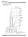
1
INSTALLATION MANUAL
M-SC3.5
- 3000 RPM -
Marine diesel generating set 230V / 50Hz
Digital Diesel Control
Art.nr. 40261141
WHISPER POWER BV
Kelvinlaan 82
9207 JB Drachten
Netherlands
Tel.: +31-512-571550
Fax.: +31-512-571599
www.whisperpower.eu
V1. May 2010
CONTENTS
CONTENTS:
1
INSTALLATION ............................................................................................................................................................... 3
1.1
Location .............................................................................................................................................................. 3
1.2
Instructions for optimal sound and vibration insulation ............................... Fout! Bladwijzer niet gedefinieerd.
Steel base plate ................................................................................................................................. 3
1.2.1
1.2.2
Further recommendations ................................................................................................................. 3
1.3
Ventilation........................................................................................................................................................... 4
1.4
Connections ....................................................................................................................................................... 5
1.4.1
Fuel supply ........................................................................................................................................ 5
1.4.2
Cooling .............................................................................................................................................. 7
1.4.3
Exhaust system ......................................................................... Fout! Bladwijzer niet gedefinieerd.
1.4.4
Control system ................................................................................................................................ 11
1.4.5
AC power system (230 Volt) ............................................................................................................ 15
2
INSTALLATION SPECIFICATIONS .............................................................................................................................. 17
2.1
M-SC3.5 installation table................................................................................................................................. 17
2.2
Commissioning table ........................................................................................................................................ 17
2.3
Installation specifications M-SC3.5................................................................................................................... 18
2.4
Specification of the accessories ....................................................................................................................... 18
2.5
Installation materials M-SC3.5.......................................................................................................................... 19
3
DIAGRAMS & DRAWINGS ........................................................................................................................................... 24
3.1
DC wiring diagram ............................................................................................................................................ 24
3.2
Wiring names and colours ................................................................................................................................ 27
3.3
AC wiring diagram 230V / 50Hz ....................................................................................................................... 28
3.4
Dimensions MasterView Easy Panel ................................................................................................................ 29
Dimensions M-SC3.5 ....................................................................................................................................... 29
3.5
4
MASTERBUS ................................................................................................................................................................. 30
4.1
What is MasterBus? ......................................................................................................................................... 30
4.2
Event-based commands ................................................................................................................................... 30
4.3
How to set up a MasterBus network ................................................................................................................. 31
2
May 2010 / M-SC3.5 / EN
INSTALLATION
1 INSTALLATION
This installation manual is valid for the following models:
1.2 INSTRUCTIONS FOR OPTIMAL SOUND
Part
number
Position the generating set as low as possible in the
vessel. As the generating set is already secured to the
base frame by means of flexible engine mountings, the
frame can be mounted directly to the vessel’s main
structure.
AND VIBRATION INSULATION
Description
M-SC3.5 / 230V 3000rpm wet exhaust
MasterBus controlled
M-SC3.5 / 230V 3000rpm wet exhaust
41200506
MasterBus controlled - ungrounded
For other models see our website: www.whisperpower.eu.
41200500
To ensure reliability and durability of the equipment, it is
very important that the installation is carried out with the
utmost care and attention. To avoid problems, such as
temperature problems, noise levels, vibration, etc. the
instructions set out in this manual must be followed and all
installation work must be carried out professionally.
1.1 LOCATION
Since Whisper generating sets have extremely compact
dimensions, they can be installed in tight locations. Please
consider that even almost maintenance-free machinery
must still remain accessible.
When selecting the location area in which to mount the
generating set, make sure there is sufficient room to carry
out any maintenance work. The unit must be easily
accessible on the service side and on the distribution side
to have access to the raw water pump and oil strainer.
Please also note that in spite of the automatic oil pressure
sensor it is still essential that the oil level is checked
regularly.
Figure 1: Mounting of the Whisper generating set.
EN / M-SC3.5 / May 2010
1.2.1
Steel base plate
However to keep resonant vibrations at a minimum, it is
recommended to mount the generating set on a solid steel
base plate, approx. 30 mm weighing approx. 44 kg or 50%
of the weight of the generating set. The engine draws its
inlet combustion air through several holes in the capsule
base. Therefore the capsule must be fitted with sufficient
clearance between the capsule underside and the base
plate. A steel base plate is available from Whisper Power
as an optional accessory (ref. fig. 23, page 21).
1.2.2
Further recommendations
Whisper generating sets are standard equipped with a
"GRP" (Glass Reinforced Plastic) sound cover. The
canopy has been designed to give effective sound
insulation. For optimum sound and vibration dampening,
the following factors should be considered.
1
Avoid mounting the generating set in close proximity
to thin walls or floors that may cause resonance.
2
Sound dampening is extremely poor if the generating
set is mounted on a light weight flimsy surface such
as plywood which will only amplify vibrations. If
mounting on a thinner surface cannot be avoided,
this should at least be reinforced with stiffening struts
or ribbing. If possible, holes should be bored or cut
through the surface to help reduce the resonance.
Covering the surrounding walls and floors with a
heavy coating plus foam will certainly improve the
situation.
X = wrong, V = OK
3
INSTALLATION
3
Never connect the base of the generating set directly
to bulkheads or tanks.
1.3 VENTILATION
The generating set normally draws air from the engine
room. Engine rooms with natural ventilation must have
vent openings of adequate size and location to enable the
generating set to operate without overheating. To allow an
ample supply of air within the temperature limits of the
generating set an opening of at least 100 cm2 is required.
A "sealed" engine compartment must have a good
extraction ventilator to maintain reasonable engine room
temperatures. High temperature of intake air reduces
engine performance and increases engine coolant
temperatures. Air temperatures above 40°C reduce the
engine power by 2% for each 5°C of rise. To minimise
these effects the engine room temperature must not be
more than 15ºC above the outside ambient air
temperature.
1 Battery POS
2 Fuel return
3 Exhaust
4 Water out
5 By-pass air vent
6 Water return
7 Water in
8 Oil strainer
Apply a combination of ventilators, blowers and air intake
ducting to meet the temperature limit. The air inlet ducts
should run to the bottom of the engine room to clear fumes
from the bilge and to circulate fresh air. Air outlets should
be at the top of the engine room to remove the hottest air.
An engine room blower should be used as an extraction
ventilator to remove air from the engine room. In cases
where it is impossible to meet the above mentioned
temperature limit by using machine room ventilation,
connections are to be made for an air inlet directly to the
enclosure. With these connections the generating set can
be directly connected to an air duct.
Air inlets should be louvered, where appropriate, to protect
the engine room and to protect the generating set from
water spray. As an extra precaution, the fitting of a cowl
ventilator with a cover box located as high as possible, is
recommended.
9 Fuel in
10 Remote cable
11 Battery NEG
12 AC cable
13 Cable fuel lift pump
Figure 2
4
May 2010 / M-SC3.5 / EN
INSTALLATION
1.4
CONNECTIONS
The generating set comes supplied with all supply lines
and output cable (i.e. electric cables, cooling water
connections, exhaust, fuel lines etc.) already connected to
the engine and generator. The supply lines are fed through
the capsule’s front base. The connections are marked as
shown in figure 2.
All electrical connections, cable types and sizes must
comply with the appropriate national regulations. Supplied
cables are rated for ambient temperatures up to 70°C. If
the cables are required to meet higher temperature
requirements, they must be run through conduits.
ATTENTION!
Before working (installation) on the system
read the section safety instructions.
1.4.1
Fuel supply
the tubing of fuel pipes could be submitted to local
regulations depending on the application of the vessel.
The fuel pipes can be plumbed to the flexible hoses which
are on the generating set and have a connection to fit to 8
mm pipe. This fuel lines fulfils CE standards and are
according to ISO 7840 A2. It is important to avoid bends in
the pipes, as they could trap air bubbles. The return pipe
should never be connected to the suction pipe. Other
consumers of diesel fuel, such as the propulsion engine
and heaters, have to be connected to separate suction
and return pipes.
4
FUEL FILTERS
A fine fuel filter is installed which requires maintenance.
Whisper Power advises to install an extra fuel filter/ water
fuel separator near the fuel tank.
Before starting your generating set for the first time follow
the fuel system bleeding procedure in the users manual.
1
FUEL TANK
Fuel tanks should be made of appropriate material such as
(stainless) steel or plastic. Steel tanks should not be
galvanised or painted inside. Condensation can occur in
metal tanks when temperature changes. Therefore, water
accumulates at the bottom of the tank and provisions
should be made for the drainage of this water.
The tank will need a filling connection, a return connection
and an air ventilation connection which will require
protection against water entry.
Some official regulations do not allow connection points at
the base of the fuel tank; in this instance connections are
to be made at the top of the tank with internal tubing down
to a few cm above the bottom of the tank.
2
FUEL LIFT PUMP
The generating set itself is equipped with a fuel lift pump;
therefore the tank can be installed at a lower level than the
generating set. The maximum suction height is 1 m. If the
pump has to lift the fuel higher than one meter an external
fuel lift pump must be installed. The control board is
already prepared to connect an extra fuel pump.
3
FUEL PIPES
When the tank is above the generating set we recommend
ending the return line on the top of the tank (A).
When the return is on the top - in case of a leakage the
return line cannot overflow because of siphoning. One will
only need a fuel cock in the fuel supply line.
When the tank is below the generating set we recommend
ending the return line on the bottom of the tank (A) below
the inlet of the supply line to discharge under the lowest
fuel level. This prevents air getting into the fuel line. Here
also one needs a fuel cock only in the supply line Both
supply and return fuel pipe lines should be appropriate
material and 8 mm outer diameter tubing. The quality of
EN / M-SC3.5 / May 2010
5
INSTALLATION
1 Fuel return;
2 Fuel supply;
3 Prefilter / water separator (optional);
5 Fuel tank;
6 Standard fuel lift pump;
7 Standard fuel filter.
Figure 3: Fuel supply (fuel tank is above the generating
set)
1 Fuel return;
2 Fuel supply;
3 Prefilter / water separator (optional);
4 Extra fuel lift pump (optional);
5 Fuel tank;
6 Standard fuel lift pump;
7 Standard fuel filter.
Figure. 4: Fuel supply (fuel tank is above the generating
set)
6
May 2010 / M-SC3.5 / EN
INSTALLATION
min.
60 cm
max.
120 cm
Figure 5: Internal
cooling system
1.4.2
1 Water level
2 Water/exhaust separator
3 Seacock
4 Waterlock
5 Air vent;
6 Water strainer;
7 Seacock.
Cooling
This should not be done in the case of a
generating set! When sailing at higher
speeds, water will be forced into the inlet
and your generating set will overflow!
Intercooling is based on a raw water pump, heat
exchanger and water-injected exhaust. The generating set
should have its own sea water (coolant water) inlet and
should not be connected to any other engine systems. A
properly installed cooling system is critical to keep engine
temperatures within an acceptable range. Ensure that the
installation complies with the following installation
instructions.
1
RAW WATER SUPPLY
For raw water supply the following installation materials
are required: -a skin fitting - a sea cock - a water strainer hoses and clamps. In order to keep the suction resistance
in the line at a minimum, the sea water intake system (i.e.
sea cock, tru-hull fitting, inlet filter, etc.) must have an
inner diameter of at least 12.5 mm diameter (1/2"). The
suction hose should be kept as short as possible. Raw
water plumbing should avoid bends as much as possible.
Restriction of raw water flow, caused by kinked hoses,
undersized pipes or connections, will reduce the engine
cooling capability. This is the main cause for overheating
of an engine. After running the generating set for the first
time, check the coolant flow rate using a stopwatch and by
holding a pail of a known volume under the wet-exhaust
outlet. The flow rate should be 8 to 12 litres /min.
2
Figure 6: Installing water intake
On motorboats and on sailing boats the water scoop for a
generating set should be fitted with the opening faced
backwards to prevent water being forced in during sailing.
Use a sealant when mounting the skin fitting.
INSTALLATION OF THROUGH HULL FITTING
It is good practice for yachts to use a hull inlet fitting with
an integrated strainer (water scoop). For propulsion
engines in motorboats the water scoop is often mounted
against the sailing direction to induce more water intake
for cooling.
EN / M-SC3.5 / May 2010
3
WATER STRAINER
Use an appropriate water strainer with connections of 12.5
mm (1/2"). Install the water strainer in a well accessible
position, (refer to figure. 5, ref 6) 5 cm above the waterline.
7
INSTALLATION
4
SIPHON BREAKER (AIR VENT)
When the point of water injection is below the waterline,
then -when the engine is stopped -there is a risk that the
cooling water may enter the engine as a result of
siphoning. To avoid this happening, the generating set is
designed to accommodate a siphon breaker (air vent). In
the standard delivery the connections are bypassed. Hose
of 12.5 mm (1/2") inner diameter should be used. If the
generating set cannot be mounted such that the bottom of
the generating set is placed above the waterline, an air
vent must be installed. Extend the water hose of the bypass 600 mm above waterline and install an air vent.
Ideally, the air vent should be mounted above the yacht
keel center line (i.e. to minimize the influence of swaying
on the water intake). The hose of the drain should go
downwards. Water must flow out freely and air has to flow
in freely as well (refer to figure 7).
Fast motorboats will lay deeper when sailing at large
speed and can cause pressure on the waterinlet. This
should be avoided to prevent fleeding the engine. If the air
vent is clogged the water hoses will not be vented when
the generating set has stopped and water can be forced
into the engine. This leads to immediate engine problems
and eventually severe damage!
Figure 7: Wrong siphon breaker hose routing
Check the air vent at regular intervals. Open, clean and
lubricate the valve as required (figure 8).
DAMAGE CAUSED BY THE INGRESS OF
WATER IN THE ENGINE IS NOT COVERED
BY WARRANTEE
On the valve is a little hose to drain a little water that could
be spilled from the valve. This hose should go down and
may not end under water, because it should ventilate air
into the valve to break the siphoning (figure 7).
Figure 8
8
May 2010 / M-SC3.5 / EN
INSTALLATION
1.4.3
Exhaust system
Water is injected in the exhaust system of the generating
set. In this way the cooling water that has passed the heat
exchanger is mixed with the exhaust gases. Temperature
and volume of the gases are thereby reduced
considerably, so that a rubber exhaust hose can be used
and the level of noise is reduced as well.
1
situated preferable along the ship’s keel center line. It is
recommended to install an extra muffler (see figure 9, ref.
2) close to the through-hull fitting.
STANDARD EXHAUST SYSTEM INSTALLATION
The generating set exhaust system must remain
completely independent and separate from the exhaust
system of any other engine on board. A water lock
prevents the generating set from being flooded by cooling
water and should be installed as close to the generating
set as possible. The lock must be large enough to hold the
entire water volume held in the hose from the top of the
goose neck to the water lock. The water lock must be
installed at the lowest point of the exhaust system (ref. to
figure 9, ref. 1). The exhaust hose must have an inner
diameter of 40 mm no less, no more-. The exhaust system
must be installed so that the back pressure inside the
exhaust does not exceed 0,8 psi 60 cm. waterpressure
(refer to paragraph 5.4.3 of the users manual) and total
length up to the outlet or water separator does not exceed
2,5 m. The exhaust hose descends from the capsule to the
water lock. Then the hose rises maximum lift 120 cm via
the "goose neck" to the through-hull exhaust outlet,
situated minimum 50 mm above the water line (refer to
figure 9, ref. 5). The "goose neck" must be vertical and
Because of the small gas flow of the small
engine it is very important to keep strictly to
the instructions above. Some mufflers and
water locks cause too high back pressure.
You are advised to use a Whisper Power
installation kit or check the back pressure
(refer to paragraph 5.4.3 of the users
manual). Too high back pressure causes the
system to fill up with water that affects the
outlet
valve
and
valve
seat.
Max. length A – B = 2.5 m. (8 ft.)
Figure 9: Standard exhaust system
1 Exhaust water lock;
2 Exhaust outlet muffler;
3 Exhaust line Ø 40 mm;
EN / M-SC3.5 / May 2010
4 Goose neck;
5 Through-hull exhaust outlet Ø 40 mm;
6 Water level.
9
INSTALLATION
Figure 10: Super silent exhaust system
1 Water level;
2 Water/exhaust separator;
3 Seacock;
4 Waterlock;
Max. length A – B = 2.5 m. (8 ft.)
Figure 11: Only after the exhaust / water separator the exhaust hose may have a length up to 7,5m.
10
May 2010 / M-SC3.5 / EN
INSTALLATION
2
"SUPER SILENT" EXHAUST SYSTEM
See figure 10. In order to reduce the noise level of the
generating set to a minimum, an option to reduce the
exhaust noise further (especially exhaust water splashing)
is an exhaust/water separator. The exhaust/water
separator allows the cooling water to be ejected through a
line separate from the exhaust fumes and also functions
as a goose neck to prevent water from flooding the engine.
The exhaust/water separator is mounted more than 60 cm
above the water level.
See figure 11. If the through-hull exhaust outlet has to be
mounted far from the generating set, an exhaust/water
separator must definitely be installed. (Total length of the
exhaust piping from generator to top of goose neck (water
separator) is more than 2,50 m.) The sea water from the
separator must run down along the shortest possible path
to the through-hull outlet.
Only when using an exhaust /water separator the exhaust
may have a length up to 7,5m after the
water/gasseparator.
However watertraps should be avoided as the fumes still
contains water and this should not accumulate in bents
(refer to figures 12 and 13). An additional outlet exhaust
muffler close to the hull outlet will help further to reduce
noise emission.
WRONG!
Fig.12: Water trap in exhaust system
WRONG!
Figure 13: Water will collect in the hanging bend of the exhaust gas hose and will cause back pressure
EN / M-SC3.5 / May 2010
11
INSTALLATION
If the generating set and the exhaust system have been
installed correctly, neighbouring boats will not be disturbed
by generating set noise, With the "super silent" exhaust
system, generating set noises are almost inaudible. For
optimal noise reduction, the sea water outlet from the
exhaust/water separator (center outlet on the unit) should
be installed below the water level to eliminate noisy
splashing of the effluent sea water.
The through-hull outlet for the exhaust fumes should not
direct the fumes directly toward the water surface as this
will cause excessive noise (refer to figure 14).
Do not direct the outlet directly toward the
water surface.
of other remote control panels such as the Digital Diesel
Control panel, the System Manager AC + Whisper panel
and the Power System Control Panel is not possible. The
Masterview Easy must be mounted on an easy accessible
location, protected against rain, moist, dust and
condensation. For good visibility avoid installing the panel
in direct sunlight.
Installation of the MasterView Easy
Below mentioned steps describe a basic installation of the
MasterView Easy in combination with the generating set.
Refer to the separate user’s manual of the Masterview
Easy if you want to add any other Mastervolt system
devices
to
the
MasterBus
network
(see
www.whisperpower.eu).
WRONG!
Figure 14
1.4.4
1
Control system
DC CONTROL SYSTEM
The electrical control system is standard in 12 Volt with
negative earth. Non- earth return is available as an option
for aluminium vessels to prevent corrosion.
All electrical wiring has been prepared on the generating
set prior to despatch from the factory. Operation of the
engine is controlled by a microprocessor based control
system called “Digital Diesel Control”. The Digital Diesel
Control Panel is integrated in the generating set.
MasterBus
The generating set is compatible with MasterBus: a fully
decentralized data network for communication between
the different Whisper Power system devices such as the
inverter, battery charger, generator, batteries and many
more. See chapter 4 for details
The generating set as well as the rest of the electrical
system can be monitored and controlled by any MasterBus
compatible remote control panel. The MasterView Easy is
a MasterBus compatible monitoring and control panel that
is standard included in the delivery of the generating set.
Important to know:
This generating set is only feasible for the connection of
MasterBus compatible remote control panels. Connection
12
Figure 15
1
See figure 15 Insert a MasterBus terminating
device into one of both communication ports (it
doesn’t matter which one) of the Digital Diesel
Control Panel on the generating set. Insert the
communication cable in the other communication
port.
Figure 16
2
See figure 16. Connect the other end of the
communication
cable
to
one
of
both
communication ports of the MasterView Easy.
May 2010 / M-SC3.5 / EN
INSTALLATION
Insert a MasterBus terminating device into the
other communication port.
3
The Masterview Easy can be flush mounted or
panel mounted on a wall or board:
During first commissioning the generator set will be
recognized by the MasterBus network automatically. This
may take a few seconds. Then the Masterview Easy will
show the initial screen.
Refer to the operation manual of the MasterView Easy for
initial settings and operating instructions.
Event based commands
One of the main features of MasterBus is the possibility of
programming for interactive operation of the connected
devices, including automatic starting and stopping of the
generator set. This is done by means of event based
commands. Refer to the operation manual of the
MasterView Easy for details about programming these
event based commands.
Figure 17
o
o
Flush mounting (see figure 17):
•
Remove the outer housing and remove the
front from the panel.
•
Make a cut out in the mounting wall and drill
the holes using the saw template in the box
or using the dimensions at the back of the
front plate.
•
Mount the MasterView Easy onto the panel
(1) and then reattach the front (2).
Panel mounting (see figure 18):
•
Remove the outer housing and remove the
front.
•
Drill the holes using the dimensions at the
back of the front plate and fasten the outer
housing (1).
•
Click the panel into the outer housing (2).
•
Reattach the front (3).
Whisper Power cannot be held responsible
for damage caused by unattended running
of the generator due to the use of event
based commands.
Using event based commands the
generator can start unexpectedly. When
working on the electrical system, the 30
Amp fuse must be removed from the Local
Control Panel and the battery plus cable
must be removed from the battery.
Connection of an emergency stop / fire alarm switch
To connect an emergency stop button or to stop the
generator automatically in case of a fire alarm, you can
use the bypass connection between wires 13 and 14 that
come from the The Digital Diesel Control Panel. See fig.
19. To do so, remove the top cover plate of the
connection box to get access to the wiring loom.
Figure 19: Location of the connection box
Disconnect the bypass between wires 13 and 14 and then
replace it by an emergency switch or a potential free fire
alarm switch with normally closed contacts (figure 20).
Figure 18
EN / M-SC3.5 / May 2010
13
INSTALLATION
included in the standard supply. A high efficiency battery
charging unit can be ordered from Mastervolt which is able
to charge both the ship’s main battery and the starter
battery. Also a small charger can be used to charge the
starter battery only, such as the IVO SMART 12/10.
Fig. 20: Connection for emergency stop / fire alarm switch
2
STARTER BATTERY
For starting, the Whisper requires a 12V starter battery
with the following capacity:
Model
Minimum capacity
M-SC3.5
55Ah
The generating set can be connected with the main engine
battery or have its own battery. We strongly recommend
the use of a separate battery for the generating set and to
keep the wiring system for the propulsion engine and the
domestic DC supply system completely separate and
individually connected to separate batteries.
3 OTHER RECOMMENDATIONS AND WARNINGS
The battery should be secured for seagoing conditions and
the terminals should be insulated. For extra safety the
battery can be enclosed in a wooden, plastic, Fiberglas
etc. (non metal) box. Even when the earth return system is
applied a negative battery cable should be used and the
vessel should not to be used as a conductor.
In the negative battery cable a 250 Amp starter battery
switch could be applied to switch off the battery. The
battery cables are supplied in a standard length of 1.5 m, if
longer cables are required a larger cross sectional area
should be considered to compensate for voltage reduction.
When two batteries are used in series to provide a 24 Volt
supply system, never take off 12 Volt (starting) power from
one of these batteries (figure 22). This will result in severe
damage to the batteries within a short time.
Figure 22
Disconnect the battery leads if electrical welding is to be
carried out, otherwise damage will be caused to the diodes
of the alternator.
Figure 21: Installation of a starter battery
However, the negative of all the batteries on the vessel
should be interconnected (when on earth) to avoid
difference in the voltage level of the earth on different
places causing trouble to electronic devices which might
be in the system.
The above recommendation is not valid for ships having
the starter battery of the propulsion engine or other
auxiliary equipment positive grounded. When this is the
case an expert should be consulted.
A battery switch may be used.
The starter battery is charged by the standard internal
charger in the alternator. An additional battery charger will
help to keep the battery in good condition when the
generating set is not used. A battery charger is not
14
As explosive hydrogen gases are discharged
during charging, the battery should be located
in a well ventilated room. Ensure that the
supplied battery cable connectors are properly
fitted and never remove during or shortly after
charging as sparking can occur, which may
ignite the hydrogen gasses.
1.4.5
AC power system (230 Volt)
Before working (installation) on the system
read the sections on safety in the users
manual.
Be sure that all electrical installations (including all safety
systems) comply with all required regulations of the local
May 2010 / M-SC3.5 / EN
INSTALLATION
authorities. All electrical safety/shutdown and circuit
breaking systems have to be installed onboard as the
generating set itself cannot be equipped with such
equipment for every possible variation.
The vessel’s power supply system should be suitable and
safe for the AC voltage which is applied and the power
that will be generated. Special attention has to be paid on
dividing the system in branches which are fused
individually.
It is absolutely essential that each and every circuit in the
on-board electrical system is properly installed by a
qualified electrician.
1 FUSE
An output fuse (from the generating set to the system)
should be installed to protect the installed electrical
system. The fuse should be sized such that the rated
generating set current is not exceeded by more than 15%.
The maximum single phase output current is as listed
below:
Model
Maximum output current
M-SC3.5 – 3000 rpm
13 Amp
The fuses must be of the slow reacting type. For electrical
motors connected to the system, a motor protection switch
must be installed.
2 GROUNDING
The AC alternator windings are not grounded. Measures
against earth insulation failures are often subject to local
regulations. The housing of the alternator and all other
metal parts are grounded. For safety reasons connect the
main ships ground to negative point of the generating set
start battery. When an ungrounded return DC system or
positive grounded DC system is applied the battery
negative should not be connected to the main ships
ground.
To make a connection between “neutral” and “ground”
could be necessary as part of a specific insulation failure
protection system.
Small pleasure craft in Europe is submitted to The
Recreational Craft Directive 94/25/EC. The guidelines of
this directive refer to (ISO 13297).
When the installation comply to this standard the “neutral”
and “ground” should be connected on the generating set
by connecting the blue (neutral) wire with the terminal on
which the yellow/green wire is connected.
EN / M-SC3.5 / May 2010
WARNING
In all situations the transfer switches between
shore, inverter and generator should switch all
connections, the phase line (L) as wel as
neutral (N). Of course this is the case when
using a Masterswitch.
Be aware that insulation protection systems can be
different for different applications and even within the ship
there could be different standards for different spaces. We
did refer to the Recreational Craft Directive that applies to
pleasure craft up to 24 m of length. Sometimes one has to
comply with other standards such as the rules of
certification societies like Lloyds Register of Shipping or
Veritas, regulations for the protection of personal, building
legislation, etc. It is of the greatest importance to have
expert advice on this issue.
3 CABLE
For the power cable we recommend the oil resistant cable
with the following cross sectional area:
Model
Cross sectional area
M-SC3.5 – 3000 rpm
3x2.5 mm² (5m. included)
For very long cables it is recommended to apply cables
with a larger cross section than the mentioned above.
4 TRANSFER SWITCH
A power source selector switch much be installed between
the generating set and the ship’s electrical supply system.
This switch must ensure that all AC consumers can be
switched off at once. This switch should also be installed
to keep the generating set and shore (grid) power systems
separate.
Transfer switches - to switch over from shore to ship or
from generating set to inverter - should be well designed to
switch over all wires including neutral (and not only phases
or line) and there should be provisions with the aid of
timers to prevent relays from chattering.
Whisper Power advises the installation of a Masterswitch
as the power source selector. This works automatically
when the generating set is not running the input remains in
the shore position and as soon as the generating set is
running the Masterswitch switches automatically after 10
seconds delay time over to the generating set position.
15
INSTALLATION SPECIFICATIONS
2 INSTALLATION SPECIFICATIONS
2.1 M-SC3.5 INSTALLATION TABLE
Figure 23
1
Install a steel foundation plate between ship’s hull and
generating set, with 4 shock mounts (ref. to figure.
23).
2
Mount the generating set directly to the foundation
plate.
3
Connect the (sea) water inlet to the strainer.
4
Connect exhaust system.
5
Connect a siphon breaker or ‘air vent’ into the cooling
circuit, if necessary.
6
Connect ‘fuel supply line’ to the water separator/ fuel
filter.
7
Connect ‘fuel return line’ to the fuel tank.
8
Connect the MasterView Easy remote panel.
9
Connect the AC cable from the AC box to the power
source selector or Mass SystemSwitch.
10 Connect plus and minus from the 12V starter battery
to the battery cables.
11 Install a Whisper Power battery charger (optional).
16
2.2 COMMISSIONING TABLE
1
Check if a siphon breaker (air vent) is necessary and
has been installed and that the drain is without bents
and air can flow in freely.
2
Open the seawater inlet valve and check all water
connections. Check if the strainer is installed above
the seawater level.
3
Check if the exhaust system is properly installed. Also
check the minimum required height of 60 cm above
sea level of the exhaust loop (goose neck). Check
length of exhaust hose, diameter of exhaust hose,
position of the waterlock, maximum lift.
4
Open the seawater outlet valve and check all water
connections.
5
Check the AC cables and the grounding.
6
Check if an AC breaker is installed before or after the
power source selector. When there is only a circuit
breaker, use it to disconnect the generating set from
the grid.
7
Check all DC connections, check if the battery switch/
circuit breaker is closed.
8
Open the fuel valve and bleed the fuel system. Ensure
there is sufficient fuel. The M-SC3.5 is self bleeding.
To check the well functioning release the bleed screw
on the high pressure fuel pump. Push the start button
activating the electric system and activating the fuel
pump. When more time is needed to bleed, push
“start” and hold on the local control panel (so not on
the MasterView Easy remote panel). Hold as long as
necessary to bleed the system. Retighten the bleed
screw when no further air bubbles are expelled.
Check if there are no air leaks in the fuel supply line
and check if the lift of the fuel is less than 1 meter.
Check if there is no air in the water fuel separator.
9
Check if the air intake in the canopy is not blocked.
10 Check the oil level and color of the oil.
11 Start the engine by pushing the start button.
May 2010 / M-SC3.5 / EN
INSTALLATION SPECIFICATIONS
12 Check when the generating set is running, the delay
of 3 – 10 seconds in the power source selector
transfer.
13 Check voltage and frequency under ‘no load’
conditions.
14 Check voltage and frequency under ‘full load’
conditions.
15 Check if the battery charger of the generating set is
working (max. 14.5 Volt).
16 Close the sound shield and check the noise level.
17 Stop the generating set and check the engine again
for leakages of oil, fuel or water.
Installation checklist
www.whisperpower.eu.
available
on
our
website:
Commissioning form
www.whisperpower.eu.
available
on
our
website:
2.3 INSTALLATION SPECIFICATIONS M-SC3.5
TECHNICAL DATA
Article no
Dimensions WxDxH
Weight
41200500
505x400x500 mm
104 kg including sound shield
Max. operation angle
Remote control
Battery capacity min.
Fuel consumption
Lift fuel pump
Cooling
Cooling pump
Minimum water supply
Crank case lube oil capacity
Alternator
Voltage regulation
Output power
Battery charger
25°
MasterView Easy (MasterBus)
12V, 55 Ah
0,7-1,5 l/hr, load dependent
electric driven 12 V DC, max. lift 1 m
indirect cooling
raw water Whisper Power self priming impeller pump, PTO driven, type K
8-10 l/min.
1.3 litre + 0.2 oil cooler, total 1.5 litre
synchronous brushless, maintenance free water cooled
capacitor
230V/50Hz : 3kWatt @ cos phi = 1
additional 12V winding including regulator (4 Amps)
2.4 SPECIFICATION OF THE ACCESSORIES
Water scoop
Inlet valve
Water strainer
Air vent
Inlet suction hose
Fuel filter/water separator
Fuel inlet and return
Exhaust hose in/out
Water lock
Water/gas separator
Anti shock mounts
Foundation plate
Battery charger (optional)
EN / M-SC3.5 / May 2010
min. 1/2” (recommended 3/4”)
min. 1/2" in 12.5 mm out (recommended 3/4” in 12.5 mm out)
12.5 mm in, 12.5 mm out
12.5 mm
12.5 mm
30 micron
8 mm
Ø 40 mm (1 5/8”)
Ø 40 mm (1 5/8”)
Ø 40 mm (1 5/8”)
art. nr. 50230552
min. 44 kg (97 Lbs)
IVO SMART 12/10; 12V / 10 Amps
17
INSTALLATION SPECIFICATIONS
2.5 INSTALLATION MATERIALS M-SC3.5
Figure 24: Installation materials battery installation kit
BATTERY INSTALLATION KIT 55 Ah
pos.
qty
article no
51
1
64000550
52
1
43011000
55
1
68230302
56
1
68230314
57
1
79006005
58
2
6503001606
59
2
6503001610
TOTAL
50230208
description
Whisper Power 12/55 Ah AGM Battery
IVO Smart 12/10 230V/50-60Hz IP65 battery charger
Terminal Cover RED 230N3V02
Terminal Cover BLACK 230N3V14
Battery switch ON/OFF with key 250A
Cable lug 16mm² / M6
Cable lug 16mm² / M10
BATTERY INSTALLATION KIT 55Ah
OPTIONAL INSTALLATION MATERIALS
• Additional installation parts
pos.
qty
article no
description
60
6501208010
Cable 16mm² red
61
6501208020
Cable 16mm² black
18
per 100 meter
per 100 meter
May 2010 / M-SC3.5 / EN
INSTALLATION SPECIFICATIONS
Figure 25: Installation materials fuel supply kit
FUEL SUPPLY KIT
pos.
qty
article no
41
2
50221203
description
Straight coupling 8 mm
42
1
50230091
Filter head strainer fuel/water separator
43
2
50221618
Parallel male coupling M14- 8 mm
44
2
50221619
Parallel male coupling M14- 10 mm
45
2
50221620
Hose connection 8 mm outer cone
46
1
50230092
Filter for strainer fuel/water separator
47
2
50221252
Nipple hose pipe 8-8
48
4
50221522
Hose clamp stainless 10-16
49
2
50221632
Copper gasket ring 18x14x1,5 mm
TOTAL
50230205
FUEL SUPPLY KIT
Note: fuel pipes / fuel hoses are not included in the delivery of the fuel supply kit.
OPTIONAL INSTALLATION MATERIALS
• Additional installation parts
pos.
qty
article no
description
48
50221522
Hose clamp stainless 10-16
50
50222020
Copper fuel pipe
51
50220063
Fuel hose
per meter
per meter
OPTIONAL INSTALLATION MATERIALS
• Additional installation parts
pos.
qty
article no
description
46
50230092
Filter for strainer fuel/water separator
EN / M-SC3.5 / May 2010
19
INSTALLATION SPECIFICATIONS
Figure 26: Installation materials Water inlet kit and Syphon breaker kit
WATER INLET KIT 12.5 mm
pos.
qty
article no
1
1
50230052
2
1
50230042
3
3
50221016
4
3
50221521
5
3m
50220055
6
1
50230062
7
1
50230067
TOTAL
50230201
description
Intake strainer 3/4"
Lever operated ball valve FF 3/4"
Male hose connection 3/4"x13
Hose clamp stainless 12-20
Cool. water hose transp.spiral 13x19mm
Nickel plated brass intake strainer 3/4"
Mouting bracket small waterstrainer 1158
WATER INLET KIT 12.5 mm
SYPHON BREAKER KIT 12.5 mm
pos.
qty
article no
1
1
50230017
2
6
50221521
3
3m
50220057
4
2
50221260
TOTAL
50230272
description
Syphon breaker valve 12.5mm (1/2”), complete (including valve assembly)
Hose clamp stainless 12-20
Cooling water hose warm water 13x21mm
Hose connector 12.5mm (1/2”)
SYPHON BREAKER KIT 12.5 MM (1/2")
20
May 2010 / M-SC3.5 / EN
INSTALLATION SPECIFICATIONS
Figure 27: Installation materials “Delta” exhaust kit ø 40 mm (1 5/8”) and water separator kit 40 mm (1 5/8”)
“DELTA” EXHAUST KIT Ø 40 mm (1 5/8”)
pos.
qty
article no
description
22
8
50221504
Hose clamp stainless 32-44 mm
23
3m
50220033
Marine exhaust hose 40 mm (1⅝”)
24
1
50230093
Waterlock 40 mm Delta
25
1
50230038
Brass hull fitting hose connection 1¼"x40
TOTAL
50230251
DELTA EXHAUST KIT 40 mm
“DELTA” WATERSCHEIDER KIT 40 mm (1 5/8”)
pos.
qty
article no
description
22
8
50221504
Hose clamp stainless 32-44 mm
23
2,5m
50220033
Marine exhaust hose 40 mm (1⅝”")
31
1
50221015
Male hose connection 1¼” x 40mm
32
1
50230044
Lever operated ball valve FF 1¼”
33
1
50230033
Brass through hull fitting 1¼” x 70
34
1
50230097
Water / gas separator Delta 40/40/40mm (1⅝")
TOTAL
50230261
DELTA WATER/GAS SEPARATOR KIT 40 mm
OPTIONAL INSTALLATION MATERIALS
• Aanvullende installatiematerialen
pos.
qty
article no
description
21
1
50201830
Elbow 90° adapter exhaust hose
22
4
50221504
Hose clamp stainless 32-44 mm
27
1
50230113
Straight coupling Delta 40mm
28
1
50230112
Elbow (45º) Delta 40mm
EN / M-SC3.5 / May 2010
21
INSTALLATION SPECIFICATIONS
Figure 28: installation materials base plate kit
BASE PLATE KIT for M-SC3.5 (3000 rpm)
pos.
61
62
63
64
65
66
67
TOTAL
22
qty
4
1
4
4
4
4
4
article no
50230552
50230012
50211449
50211251
50211438
50211447
50211241
50230207
description
Rubber mounting up to 70 kg RAB3
HD base plate 3500 yellow zinc plated
Washer spring SP M12
Bolt hexagonal socket ZP M12x40
Washer SP M10x30x1,5
Washer spring SP M10
Bolt hexagonal socket ZP M10x25
BASE PLATE KIT M-SC3.5
May 2010 / M-SC3.5 / EN
DIAGRAMS & DRAWINGS
3
DIAGRAMS & DRAWINGS
3.1 DC WIRING DIAGRAM
Figure 29a:
DC wiring M-SC3.5 grounded
(part. Nr. 51200500)
EN / M-SC3.5 / May 2010
23
DIAGRAMS & DRAWINGS
Figure 29b:
DC wiring M-SC3.5
ungrounded
(part. Nr. 51200506)
24
May 2010 / M-SC3.5 / EN
DIAGRAMS & DRAWINGS
3.2 WIRING NAMES AND COLOURS
Wire name
Battery +
Battery Glow +
Start solenoid +
Stop solenoid Stop solenoid +
Fuel valve +
Fuel valve Fuel pump +
Fuel pump Charger a
Charger b
Safety switch +
Safety switch Battery +
Battery +
Wire number
1
2
3
4
5*
6
7
8
9
10
11
12
13
14
15*
16*
Colour
White
White
White
White
White
White
White
White
Brown
Black
White
White
White
White
White
White
Cross section
2.5 mm2
2.5 mm2
2.5 mm2
2.5 mm2
2.5 mm2
1.5 mm2
1.5 mm2
1.5 mm2
1.5 mm2
1.5 mm2
1 mm2
1 mm2
1 mm2
1 mm2
2.5 mm2
2.5 mm2
Start relay +
Glow relay +
Battery Oil pressure +
Oil pressure Exhaust temp. +
Exhaust temp. Engine temp. +
Engine temp. Iac1-L
Iac1-N
Uac1-L
Uac1-N
Ground relay +
17*
18*
19*
22
23*
24
25
26
27
30
31
40
41
49*
White
White
White
White
White
White
White
White
White
White
White
White
White
White
1 mm2
1 mm2
1 mm2
1 mm2
1 mm2
1 mm2
1 mm2
1 mm2
1 mm2
1 mm2
1 mm2
1 mm2
1 mm2
1 mm2
Red
Black
Green/yellow
16 mm2
16 mm2
6 mm2
Battery +
Battery Earth wire
* Ungrounded versions only (part nr. 51200506)
EN / M-SC3.5 / May 2010
25
DIAGRAMS & DRAWINGS
3.3 AC WIRING DIAGRAM 230V / 50HZ
EARTH AND NEUTRAL
NOT CONNECTED
230V 50Hz
EARTH AND NEUTRAL
CONNECTED
230V 50Hz
Figure 30 AC wiring diagram
26
May 2010 / M-SC3.5 / EN
DIAGRAMS & DRAWINGS
3.4 DIMENSIONS MASTERVIEW EASY PANEL
Figure 31: Dimensions of the panel without and with outer casing. All dimensions are in mm (inch)
3.5 DIMENSIONS M-SC3.5
Top view
Aufsicht
Box
dimensions:
Kastenabmessungen:
L nge
: 505 mm
• width: 505 mm [19.9 inch]
Breite
: 400 mm
• depth: 400 mm [15.7 inch]
H he
: 500 mm
• height: 500 mm [19.7 inch]
86[229
kg Lbs]
•Gewicht
weight: 104: kg
Figure 32: Dimensions in mm [inch]
Serviceseite
side
Service
CONNECTIONS
• exhaust:
• fuel hose:
• sea water in:
• air vent connection:
EN / M-SC3.5 / May 2010
40 mm
8 mm
13 mm
13 mm
• battery +:
• battery -:
• cables:
• remote control:
16 mm² red (included)
16 mm² black (included)
3x 2.5 mm2 (5 meter included)
MasterBus communication
cable (15 meter included)
27
MASTERBUS
4 MASTERBUS
monitoring, control and configuration of all connected
MasterBus equipment.
4.1 WHAT IS MASTERBUS?
All devices that are suitable for
MasterBus are marked by the MasterBus
symbol.
MasterBus is a fully decentralized data network for
communication between the different Mastervolt system
devices. It is a CAN-bus based communication network
which has proven itself as a reliable bus-system in
automotive applications. MasterBus is used as power
management system for all connected devices, such as
the inverter, battery charger, generator and many more.
This gives the possibility for communication between the
connected devices, for instance to start the generator
when the batteries are low.
MasterBus reduces complexity of electrical systems by
using UTP patch cables. All system components are
simply chained together. Therefore each device is
equipped with two MasterBus data ports. When two or
more devices are connected to each other through these
data ports, they form a local data network, called the
MasterBus. The results are a reduction of material costs
as only a few electrical cables are needed and less
installation time.
For central monitoring and control of the connected
devices Whisper Power offers a wide range of panels
which show full status information of your electrical system
at a glance and a push of a button. Four different panels
are available, from the small Mastervision compatible 120
x 65mm LCD screen up to the full colour MasterView
System panel. All monitoring panels can be used for
Event source:
Battery pre low
Event target:
GEN M-SC3.5
Event command:
Auto start
Event data:
Copy
28
New devices can be added to the existing network in a
very easy way by just extending the network. This gives
the MasterBus network a high degree of flexibility for
extended system configuration, not only today, but in the
future as well!
Whisper Power also offers several interfaces, making even
non-MasterBus devices suitable to operate in the
MasterBus network.
4.2 EVENT-BASED COMMANDS
With MasterBus each device can be programmed to
initiate an action at an other connected device. This is
done by means of event based commands.
Example: if the state of charge of the service batteries is at
40%, the generator must be started.
In this example, the MasterBus network should at least
exist of the following devices: a MasterView Easy panel for
programming of event based commands, a MasterShunt
to measure the state of charge of the service batteries and
a Whisper generator set as power supply for the battery
charger.
As the state of charge of the service batteries is measured
by the MasterShunt, this device is considered as the Event
source. The Whisper generator set is the device that
should initiate an action (starting the generator to charge
the service batteries), and is therefore considered to be
the target. This means that you should use the
MasterView Easy panel to program the MasterShunt as
follows:
Select from list of events sources
(see manual of the MasterShunt)
Select from the device list (devices connected to the
MasterBus)
Select event command from the list of event commands of
the target (see manual of the of the Generator)
Select event action from the list of event commands of the
target (see manual of the of the Generator)
May 2010 / M-SC3.5 / EN
MASTERBUS
4.3 HOW TO SET UP A MASTERBUS
NETWORK
Each device that is suitable for the MasterBus network is
equipped with two data ports. When two or more devices
are connected to each other through these ports, they
form a local data network, called the MasterBus.
Keep the following rules in mind:
The electric power for the network comes from the
connected devices.
At least one device in the network should have
powering capabilities (see specifications).
One powering device can power up to three
nonpowering devices. As all powering devices are
galvanically isolated, multiple powering devices are
allowed.
Connections between the devices are made by
standard straight UTP patch cables. Whisper Power
can supply these cables. These cables are also
commonly available at computer supply stores.
1
2
3
4
5
6
7
8
1
2
3
4
5
6
7
8
Figure 35:
Do not make ring networks.
OK
Figure 33:
As with all high speed data networks, MasterBus
needs a terminating device on both ends of the
network.
Fig. 36:
Do not make T-connections in the network.
Figure 34:
Figure 37:
EN / M-SC3.5 / May 2010
29
NOTES
NOTES
30
May 2010 / M-SC3.5 / EN
Kelvinlaan 82, 9207 JB Drachten, Netherlands
Tel : + 31-512-571550 / Fax : + 31-512-571599
www.whisperpower.eu / [email protected]