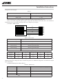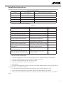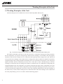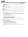
1
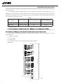
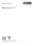
ERJC 36, 42 R
by johnson controls
Ref:
GB
Heat pump Multisplit Inverter Condensing units
Installation Instructions
Johnson Controls Manufacturing España, S.L. is participating in the EUROVENT Certification Programme.
Products are as listed in the EUROVENT Directory of Certified Products, in the program AC1, AC2,
AC3, LCP and FC.
The LCP program covers air condensed water chillers and heat pumps of up to 600 kW
User Notice
The total capacity of the indoor units which runs at the same time can not exceed 150% of
that of the outdoor units; otherwise, the cooling (heating) effect of each indoor unit would be poor.
Switch the main power on 8 hours before start the unit, helpful for a successful startup.
It is a normal phenomenon that the indoor unit fan will still run for 20~70 seconds after the
indoor unit receives the “stop” signal so as to make full use of after-heat for the next operation.
they can back to the normal condition by harmonizing their running modes: the cooling mode is
compatible with the dehumidifying mode and the fan mode can go with any other mode. If the
supply power fails when the unit is running, then the indoor unit will send the “start” signal to the
outdoor unit three minutes later after power recovery.
During installation, the communication cable and the power cord must not be twisted
together but instead separated with an interval of at least 2cm; otherwise the unit is likely to run
abnormally.
Cautions for the Debugging and Maintenance Personnel:
During debugging and maintenance, prior to the startup of the compress make sure the heating
belt of the compressor has been energized for at least eight hours! Once the compressor is started,
it must be guaranteed that it works continuously for at least 30 minutes, otherwise it would be
damaged!
This series outdoor units are matched with the free macth series R410A GMV multi VRF
indoor units under the same working conditons exported to European Union.
This product must not be disposed together with the domestic waste. This product
has to be disposed at an authorized place for recycling of electrical and electronic
appliances.
Thank you for purchasing YORK air conditioners. Before use, please read this manual
carefully and keep it properly for further reference.
by johnson controls
Contents
Safety Precautions....................................................................................... 4
Installation Instructions............................................................................... 5
1 Installation Location and Matters Needing Attention.......................................... 5
2 Installation of the Outdoor Unit........................................................................... 7
3 Connection between Indoor and Outdoor Units .................................................. 9
4 Refrigerant Charging and Trial Running .................................................................. 11
Working Principles of the Unit ................................................................. 14
Parts and Components of the Unit ............................................................ 15
Maintenance .............................................................................................. 16
1 Check before the Seasonal Use ......................................................................... 16
2 Check after the Seasonal Use ............................................................................ 16
Troubleshooting ........................................................................................ 17
1 Please check the following items before contact the maintenance serviceman. 17
................................. 18
3 Error description ................................................................................................ 18
4 After-Sales Service ............................................................................................ 24
Function Description................................................................................. 25
Performance Parameters ........................................................................... 26
3
by johnson controls
Safety Precautions
Ⅰ Safety Precautions
Please read this manual carefully before use and operate correctly as instructed in this manual.
Please especially take notice of the following two symbols:
Warning! It indicates improper operation which will lead to human casualty or sever injury.
Cuation! It indicates improper operation which will lead to injury or property damage.
Warning!
◆ The installation should be committed to the appointed service center; otherwise it all cause water
leakage, electric shock or fire etc.
◆ Please install the unit where is strong enough to withstand the weight of the unit; otherwise, the unit
would fall down and cause injury or death.
◆ The drain pipe should be installed as instructed in the manual to guarantee the proper drainage;
meanwhile it should be insulated to prevent condensing; otherwise the improper installation would cause
water leakage and then wet the household wares in the room.
◆ Do not use or place any inflammable or explosive substance near the unit.
◆ Under the occurrence of an error (like burning smell etc.), please cut off the main power supply of the
unit.
◆ Keep good ventilation in the room to avoid oxygen deficit.
◆ Never insert your finger or any other object into the air outlet/inlet grille.
◆ Please take notice of the supporting frame of the unit to see if it is damaged over the long time period
of use.
◆ Never refit the unit and contact the sales agent or the professional installation personnel for the repair
or relocation of the unit.
◆ Non-professional personnel are prohibited to dismantle the electric box owing to the high voltage of
the outdoor unit.
An all-pole disconnection switch having a contact separation of at least 3mm in all poles should be
connected in fixed wiring.
Cuation!
◆ Before installation, please check if the power supply corresponds with the requirement specified on the
nameplate and also check its security.
◆ Before use, please check if the piping and wiring are correct to avoid water leakage, refrigerant
leakage, electric shock, fire etc.
◆ The main power supply must be earthed to avoid the hazard of electric shock and never connect this
earth wire to the gas pipe, running water pipe, lightening rod or phone cable’s earth lead.
◆ Turn off the unit after it runs at least five minutes; otherwise its service life will be shortened.
◆ Do not allow children operate this unit.
◆ Do not operate this unit with wet hands.
◆ Cut off the main power supply prior to the cleaning of the unit or the replacement of the air filter.
◆ When the unit is not to be used for a long time, please cut off the main power supply of the unit.
◆ Do not expose the unit to the moist or corrosive circumstances.
◆ Never step on the unit or place any object on it.
◆ It is suggested to have a power-on test annually.
4
1
by johnson controls
Installation Instructions
Installation Instructions
1 Installation Location and Matters Needing Attention
The installation of the unit must comply with the national and local safety regulations. The
installation quality directly affects the normal use, so the user should not carry out the installation
personally. Instead, the installation and debugging should be done by the professional personnel.
Only after that, can the unit be energized.
a. How to select the installation location for the indoor unit
1) Where there is no direct sunlight.
2) Where the top hanger, ceiling and the building structure are strong enough to withstand the weight of
the unit.
3) Where the drain pipe can be easily connected to outside.
5) Where the refrigerant pipe of the indoor unit can be easily led to outside.
7) Where there is no corrosive gas, heavy dust, salt mist, smog or moisture.
b. How to select the installation location for the outdoor unit
1) The outdoor unit must be installed where the bearing surface is stable and secure enough.
2) The outdoor unit and indoor unit should be placed as close as possible to minimize the length and
bends of the refrigerant pipe.
3) Do not install the outdoor unit under the window or between the buildings to prevent the normal
running noise entering the room.
5) The outdoor unit should be installed where ventilation is in good condition so that the unit can take in
and discharge enough air.
dust, salt fog and other severely polluted air.
No air guiding pipe is allowed to be installed at the air inlet/outlet of the outdoor unit. Under
the heating mode, the condensate water would drip down from the base frame and would be frozen
when the outdoor ambient temperature is lower than 0ºC(32 ºC). Besides, the installation of the
outdoor unit should not affect the heat radiation of the unit.
CUATION !
The unit installed in the following places is likely to run abnormally. If unavoidable, please contact the
professional personnel at the YORK appointed service center. ① where is full of oil; ② alkaline soil off the
sea; ③ where there is sulfur gas(like sulfur hot spring); ④ where there are devices with high frequency
(like wireless devices, electric welding devices, or medical equipments); ⑤ special circumstances.
c. Electric Wiring
1) The installation must be done in accordance with the national wiring regulations.
2) Only the power cord with the rated voltage and exclusive circuit for the air conditioning can be used.
3) Do not pull the power cord by force.
4) The electric installation should be carried out by the professional personnel as instructed by the local
laws, regulations and also this manual.
5) The diameter of the power cord should be large enough and once it is damaged it must be replaced by
2
5
by johnson controls
Installation Instructions
the dedicated one.
6) The earthing should be reliable and the earth wire should be connected to the dedicated device of the
building by the professional personnel. Besides, the air switch coupled with the leakage current protection
switch must be equipped, which is of enough capacity and of both magnetic and thermal tripping functions in
case of the short circuit and overload.
Table 1
Power Supply
Capacity of the Air Switch
Recommended Cord
(pieces× sectional area)
ERJC(36)R
220-240V~ 50Hz
32A
6mm2× 3
ERJC(42)R
220-240V~ 50Hz
32A
6mm2× 3
Models
d. Earthing Requirements
2) The yellow-green line of the air conditioner is the earth line and can not be used for other purpose, cut
3) The reliable earth terminal should be provided and the earth wire can not be connected to any of the
following places.
① . Running water pipe;
② . Coal gas pipe;
③ . Sewage pipe;
④ . Other places where the professional personnel think unreliable.
ERJC(42)R
INDOOR UNIT D
XT5
INDOOR UNIT C
XT4
INDOOR UNIT B
XT3
INDOOR UNIT A
XT2
OUTDOOR UNIT
INDOOR UNIT E
XT6
L
N
POWER
XT1
Fig.1
6
3
by johnson controls
Installation Instructions
ERJC(36)R
POWER
INDOOR UNIT A
INDOOR UNIT B
INDOOR UNIT C
INDOOR UNIT D
XT5X
T4
XT3X
T2
N L
XT1
OUTDOOR UNIT
Fig.2
e. Noise Precautions
1) The air conditioning unit should be installed where ventilation is in good condition, otherwise the
working capability of the unit would be reduced or working noise would be increased.
2) The air conditioning unit should be installed on the base frame which is stable and secure uncouth to
withstand the weight of the unit; otherwise it would incur vibration and noise.
3) During the installation, a consideration should be taken that the produced hot air or noise should not
affect neighbors and surroundings.
4) Do not stack obstacles near the air outlet of the outdoor unit; otherwise it would reduce the working
capability of the unit or increase the working noise.
5) In the event of the occurrence of abnormal noise, please contact the sales agent as soon as possible.
f. Accessories for Installation
Refer to the packing list for the accessories of the indoor and outdoor units respectively.
2 Installation of the Outdoor Unit
a. Precautions for the Installation of the Outdoor Unit
The following rules should be followed when the installation location is being considered so as to let the
unit run well enough.
1) The discharged air from the outdoor unit won’t return back and enough space should be left for
maintenance around the unit.
2) The installation location should be in good condition so that the unit is able to take in and discharge
enough air. Besides, make sure there is no obstacle at the air inlet/outlet of the unit. If there is, remove it.
3) The unit must be installed where it is secure enough to support the weight of the unit and capable of
reducing to some extent noise and vibration to make sure they do not bother your neighbors.
4) The designated lifting hole must be used for lifting the unit and protect the unit carefully during lifting
to prevent damaging the mental sheet which would result in rusting in future.
5) The unit should be installed where there is as little as direct sunlight.
6) The unit must be installed where the rain water and defrosting water can be drained.
7) The unit must be installed where the unit won’t be covered by the snow and won’t be affected by
rubbish and oil fog.
8) Rubber or spring shock absorbers should be used during the installation of the outdoor unit to meet the
noise and vibration requirements.
9) The installation dimensions should meet the requirement covered in this manual and the outdoor unit
10) The installation should be carried out by the professionally skilled personnel.
b. Installation of the Outdoor Unit
1) Outline Dimension of the Outdoor Unit.
4
7
by johnson controls
Installation Instructions
ERJC(36)R
ERJC(42)R
1087
1015
572
362
121 76
412
110 76
340
378
440
401
99
96
450
350
840
1103
1022
950
631
192
191
Fig.3
Fig. 4
2) During the transportation of the outdoor unit, two lifting ropes long enough must be used in four
directions and the separation angle must be less than 40°prevent the center of unit deviating.
he support leg and base frame of the unit.
4) The unit should be installed on a concrete base frame with a height of 10cm.
5) The installation space of the unit should be as required in Fig.5.
Installation Space Requirements of the Outdoor Unit: ERJC(36)R 、ERJC(42)R
>1000
>2000
>500
>500
>500
>500
>2000
Fig.5
3 Connection between Indoor and Outdoor Units
a. Wiring of the Power Cord
CAUTION !
A breaker must be installed, capable of cutting off the power supply for the whole system.
1) Open the side plate.
2) Let the power cord go through the rubber ring.
3) Connect the power card to the terminals “L”, “N” and also the earthing bolt, and then connect the
wiring terminals “N(1),2,3” of the indoor unit to those of the outdoor unit correspondingly.
4) Fix the power cord with wire clips.
8
5
by johnson controls
Installation Instructions
b. Capacity Level and Capacity Code of the Indoor and Outdoor Units
Table 2
Indoor Unit
Outdoor Unit
Capacity Level
Capacity Code
09
25
12
35
18
50
21
60
24
71
36
100
42
120
1) The outdoor unit with capacity level 36 can drive up to four sets of indoor units, while the outdoor unit
42 can drive up to five.
2) The sum of the capacity codes of the indoor units should be among 50%-150% of that of the outdoor
unit.
c. Allowable Length and Height Fall of the Refrigerant Pipe
Table 3
Allowable Length
Refrigerant Pipe
36
42
36
42
Total Length(m)
70
80
L1+L2+L3+ L4
L1+L2+L3+ L4+ L5
Max. Length for Single Unit(m)
20
25
LX
Outdoor unit
and indoor unit
15
15
H1
Indoor unit and
indoor unit
7.5
7.5
H2
Max.
installation
altitude
Table 4: Dimension of the Refrigerant Pipe of the Indoor Unit
unit:mm
Capacity Level of the Indoor Unit
Gas Pipe
Liquid Pipe
09,12
φ9.52
φ6.35
18
φ12.7
φ6.35
21,24
φ15.9
φ9.52
d. Piping between the Indoor and Outdoor Units
1) Refer to Fig.6 for the moments of torque for tightening screws.
2) Let the flare end of the copper pipe point at the screw and then tighten the screw by hand.
3) After that, tighten the screw by the torque wrench unit it clatters (as shown in Fig.6).
4) The bending degree of the pipe can not be too small; otherwise it will crack. And please use a pipe
bender to bend the pipe.
5) Wrap the exposed refrigerant pipe and the joints by sponge and then tighten them with the plastic tape.
6
9
by johnson controls
Installation Instructions
Flare Nut
Pipe
Pipe
Torque Wrench
Ordinary
Fig. 6
Table 5:Moments of Torque for Tightening Screws
Diameter
Wall Thickness(mm)
Moment of Torque
φ6.35mm
≥ 0.5
15-30(N·m)
φ9.52mm
≥ 0.71
30-40(N·m)
φ12.7mm
≥1
45-50(N·m)
φ15.9mm
≥1
60-65(N·m)
CUATION !
① .During the connection of the indoor unit and the refrigerant pipe, never pull any joints of the indoor
unit by force; otherwise the capillary pipe or other pipe may crack, which then would result in leakage.
② .The refrigerant pipe should be supported by brackets, that is, don’t let the unit withstand the weight of
it.
CUATION !
For the GMV multi VRF system, each pipe should be labeled to tell which system it belongs to avoid
mistaken inaccurate piping.
e. Installation of the Protection Layer of the Refrigerant Pipe
1) The refrigerant pipe should be insulated by the insulating material and plastic tape in order to prevent
condensing and leaking.
2) The joints of the indoor unit should be wrapped with the insulating material and no gas is allowed on
the joint of the indoor unit, as shown in Fig.7.
No gap
Fig.7
CUATION !
After the pipe is protected well enough, never bend it to form a small angle; otherwise it would crack or
break.
f. Wrapping the pipe with tape
10
7
by johnson controls
Installation Instructions
1) Bundle the refrigerant pipe and electric wire together with tape, and separate them from the drain pipe
2) Wrap the pipe from the bottom of the outdoor unit to the top of the pipe where it enters the wall.
During the wrapping, the later circle should cover half of the former one.
3) Fix the wrapped pipe on the wall with clamps.
CAUTION !
① . Do not wrap the pipe too tightly; otherwise the insulation effect would be weakened. Additionally,
make sure the drain hose is separated from the pipe.
②.
room.
4 Refrigerant Charging and Trial Running
a. Refrigerant Charging
1) The refrigerant has been charged into the outdoor unit before shipment, while additional refrigerant
2) Check if the liquid valve and the gas valve of the outdoor unit are closed fully.
by the vacuum pump.
Manometer
Manometer
“HI” knob
“LO” knob
Vacuum pump
Hose
Gas Valve
Fig.8
4) When the compress is not running, charge the R410A refrigerant into the refrigerant pipe from the
liquid valve of the outdoor unit (do not do it from the gas valve).
b. Calculation of the Additional Refrigerant Charge
1) Refrigerant Charge in the Outdoor Unit before Shipment
Table 6
Model
ERJC(36)R
ERJC(42R
Refrigerant Charge (kg)
3.6
4.8
Notes:
① . The refrigerant charge mentioned in the table above is not included those charged additionally in the
indoor unit and the refrigerant pipe.
② . The amount of the additional refrigerant charge is dependent on the diameter and length of the liquid
refrigerant pipe which is decided by the actual yield installation requirement.
③ . Record the additional refrigerant charge for future maintenance.
2) Calculation of the Additional Refrigerant Charge
If the total refrigerant pipe length (liquid pipe) is smaller than that listed in the table below, no additional
8
11
by johnson controls
Installation Instructions
refrigerant will be charged.
Table 7
Model
Total Liquid Pipe Lenght (a+b+c+d+e)
ERJC(36)R
≤ 40m
ERJC(42)R
≤ 50m
Additional Refrigerant Charge2=∑Extra Liquid Pipe Length×22g/m( liquid pipe 1/4’’).
Note: if the total refrigerant pipe length is larger than that listed in the table above, the additional
refrigerant for the extra length of the pipe needs to be charged as per 22g/m.
3) Example : ERJC (42) R
e
d
c
b
a
Fig.9
Table 8 Indoor Unit
Serial No.
Model
Indoor Unit ⑤
Ducted Type EUKC(09)R
Indoor Unit ④
Ducted Type EUKC(09)R
Indoor Unit ③
Ducted Type EUKC(09)R
Indoor Unit ②
Ducted Type EUKC(09)R
Indoor Unit ①
Ducted Type EUKC(18)R
Table 9 Liquid Refrigerant Pipe
Serial No.
e
d
c
b
a
Diameter
φ6.35
φ6.35
φ6.35
φ6.35
φ9.52
Length
20m
20m
15m
5m
5m
The total length of each liquid refrigerant pipe is: e+d+c+b+a=20+20+15+5+5=65m. Thus, the minimum
additional refrigerant charge=(65-50)× 0.022=0.33kg (Note: no additional refrigerant is needed for the liquid
pipe within 50m).
4) Additional Refrigerant Charge Record
Table 10 Indoor Unit
No.
Indoor Unit Model
Additional Refrigerant Charge(kg)
1
2
……
N
Total
12
9
by johnson controls
Installation Instructions
Table 11 Refrigerant Pipe
Diameter
Total Length(m)
Additional Refrigerant Charge(kg)
Φ15.9
Φ12.7
Φ9.52
Φ6.35
Total
c. Items to be checked after the Installation
Table 12
Items to be Checked
Possible Errors
Has each part and component the of unit
installed securely?
Is the thermal insulation sufficient?
The unit may fall off, vibrate or generate
noise.
The cooling (heating) capacity may be
poor.
Dews and water drops may be generated.
Does the drainage go well?
Dews and water drops may be generated.
Is the actual power voltage in line with
the value marked on the nameplate?
The unit may break down or some
components may be burnt out.
Are the wiring and the piping correct?
The unit may break down or some
components may be burnt out.
Has the unit been earthed reliably?
There may be a danger of electric shock.
Does the wire meet the regulated
requirement?
The unit may break down or the
component may be burnt out.
Is there any obstacle at the air inlet/outlet
of the indoor/outdoor unit?
The cooling (heating) capacity may be
poor
Have the length of the refrigerant pipe
and the refrigerant charge been recorded?
It may be hard to know the exact
refrigerant charge.
Has the gas leakage test been taken?
Check Results
d. Trial Running
1) Check before the Trial Running
① .Check if the appearance of the unit and the piping system are damaged during the transportation.
② .Check if the wiring terminals of the electronic component are secure.
③ .Check if the rotation direction of the fan motor is right.
④ .Check if all valves in the system are fully opened.
2) Trial Running
① .The trial running should be carried out by the professionally skilled personnel on the premise that all
items listed above are in normal conditions.
② .Let the unit energized and switch the wired controller or the remoter controller to “ON”.
③ .The fan motor and compressor of the outdoor unit will run automatically in one minute.
④ .If there is some unusual sound after the compressor is started, turn off the unit for an immediate
check.
10
13
by johnson controls
Working Principles of the Unit
Ⅲ Working Principles of the Unit
Schematic Diagram of Free Match Series Inverter Heat Pump Multi VRF System
M
Fig. 10 Schematic Diagram of Free Match Series Inverter Heat Pump Multi VRF System
The outdoor and indoor units start to work once the power is switched on. During the cooling operation,
the low temperature, low pressure refrigerant gas from the heat exchanger of each indoor unit gets together
and then is taken into the compressor to be compressed into high temperature, high pressure gas, which will
soon go to the heat exchanger of the outdoor unit to exchange heat with the outdoor air and then is turned into
refrigerant liquid. After passing through the throttling device, the temperature and pressure of the refrigerant
liquid will further decrease and then go the main valve. After that, it will be divided and go to the heat
exchanger of each indoor unit to exchange heat with the air which needs to be conditioned. Consequently, the
refrigerant liquid become low temperature, low pressure refrigerant gas again. Such a refrigeration cycle goes
round and round to achieve the desired refrigeration purpose. During the heating operation, the four-way valve
is involved to make the refrigeration cycle run reversely. The refrigerant radiates heat in the heat exchanger of
the indoor unit (so do the electric heating devices) and absorb heat in the heat exchanger of the outdoor unit
for a heat pump heating cycle so as to achieve the desired heating purpose.
14
11
by johnson controls
Parts and Components of the Unit
Ⅳ Parts and Components of the Unit
System Structure
Outdoor Unit
Cassette Type
Indoor Unit
Duct Type Indoor
Unit(Round air
outlet)
Wall Mounted
Indoor Unit
Fig. 11
Duct Type Indoor
Unit(Rectangular
air outlet)
For the free match series DC inverter GMV multi VRF air conditioning system, one outdoor unit is able to
drive up to five indoor units which can be cassette type, duct type, wall-mounted or floor ceiling type. Among
them, the cassette type and the wall-mounted indoor units should be controlled by the remote controller, while
the ducted type can be controlled by either the remote controller or the wired controller. The outdoor unit will
run as long as any one indoor unit receives the running command, and all indoor units stops once the outdoor
units is turned off.
12
15
by johnson controls
Maintenance
Maintenance
WARNING !
① . The unit can only be cleaned after the unit is turned off and the main power is cut off; otherwise it
would cause an electric shock hazard.
② . Do not dampen the air conditioner, as it would cause a electric shock hazard and never rinse the unit
with water in any event.
CUATION !
① . Volatile liquid, like thinner, gasoline etc would damage the appearance of the air conditioning unit.
(Only use the soft dry cloth or the wet cloth with neutral detergent clean the outer shell of the air conditioning
unit)
② . Do not clean the outer shell of the air conditioning unit with more than 45 ºC hot water to prevent
discoloration or deformation.
③.
1 Check before the Seasonal Use
1) Check if the inlet/outlet of the indoor/outdoor unit is clogged.
2) Check if the earth lead is earthed reliably.
3) Check if the batteries of the remote controller are replaced.
5) Check if the installation of the outdoor is secure. If there is something abnormal, please contact the
YORK appointed service center.
6) When restarting the unit which is not used for a long time, switch on the main power supply eight
hours ahead, helpful for a successful startup.
2 Check after the Seasonal Use
units.
2) Cut off the main power supply of the air conditioning system.
3) Remove the dust and the foreign matters of the outdoor unit.
4) In the event of rusting, use the anti-rust paint to stop spreading of rust.
Refer to the Installation and Operation Manual of each indoor unit respectively for detailed
maintenance.
16
13
by johnson controls
Troubleshooting
Troubleshooting
WARNING !
① . In the event of abnormal conditions (like, stinky smell), please shut off the main power supply
immediately and then contact the YORK appointed service center; otherwise the continuous abnormal running
would damage the air conditioning unit and also would cause ele
② . Do not repair the air conditioning personally but instead contact the professionally skilled personnel
YORK
1 Please check the following items before contact the maintenance serviceman.
Table 13
Conditions
The unit does not run
Causes
Corrective Actions
Broken fuse or opened breaker
Change the fuse or close the breaker
Power off
Restart the unit when power on
Loosened power supply plug.
Plug the power supply properly.
Change new batteries
of the remote controller
The unit stops soon
after it starts
Cooling/Heating
is abnormal
Remoter controller out
of the control scope
Keep the control distance within 8 meters.
Clogged inlet/outlet of the
indoor/outdoor unit
Clear the obstacle
Clogged inlet/outlet of the
indoor/outdoor unit
Clear the obstacle
Improperly set temperature
Adjust the setting of the remote
or wired controller.
Too low set fan speed
Adjust the setting of the remote
or wired controller.
Incorrect air direction
Adjust the setting of the remote
or wired controller.
Opened door and window
Close the door and window
Direct sunlight
Hang a curtain or blinds over the window.
Too much people in the room
Too much heat sources in the room
Reduce the heat sources
Note:
If the air conditioner still runs abnormally after the above check and handling, please contact the
maintenance serviceman at the local appointed service center and also give a description of the error occurred
as well as the model of the unit.
14
17
by johnson controls
Troubleshooting
2 The conditions listed below are not classified into errors
Table 14
Conditions
The unit does not run
The unit blows out mist
The unit generates noise
The unit blows out dust.
The unit emits odors.
Causes
When restart the unit soon after it is
stopped.
The overload protection switch of the unit
let the startup delayed for three minutes.
As soon as power is on.
The unit will stand by for approximate
one minute.
When the cooling operation starts.
The hi-humidity air indoor is cooled
quickly.
The unit “clatters” as soon as it starts
running.
It is the sound generated during the
initialization of the electronic expansion
valve.
The unit “swishes” during the cooling
operation.
It the sound when the refrigerant gas runs
inside the unit.
The unit “swishes” when it is started or
stopped.
It is the sound when the refrigerant gas
stops running.
The unit “swishes” when in it is and
after the running.
It is the sound when the draining system
is operating.
The unit “squeaks” when it is in and
after the running.
It is the sound of frication generated by the
skin plate etc which swells due to the
temperature change.
When the unit restarts after it is not
used for a long time.
The dust inside the unit is blown out again.
When the unit is running.
The odors absorbed in are blown out again.
3 Error description
If some error occurs when the unit is running, the error code will be displayed on the wired controller and
the main board
of the outdoor unit.See the table before for more details about the meaning of each error.
Table 15
Indicating Lamp
Residential
AC Errors
/
/
/
18
/
Short/open
circuit of the
liquid valve
temperature
sensor
Short/open
circuit of the
gas valve
temperature
sensor
Commerical
AC Errors
Defrosting
mode 1
Defrosting
mode 2
heating overload
protection
Normal running
Short/open
circuit of he
liquid valve
temperature
sensor
Short/open
circuit of the
gas valve
temperature
sensor
Outdoor
Unit
"88"
Display
Lamp
Panel
"88"
Display
(Floor
Ceiling
Type)
Wired
Controller
Display
Running
Cooling
Heating
08
/
/
/
/
/
0A
/
/
/
/
/
Flash 3
times
/
Flash 3
times
/
Flash 3
times
/
/
oE
/
/
Shown
as Table
16
/
Flash 19
times
/
b5
b5
Shown
as Table
16
/
Flash 22
times
/
b7
b7
0C
ON
15
by johnson controls
Troubleshooting
Refrigerant
insufficiency
or blockage
protection
(available for
the residential
outdoor unit)
Short/open
circuit of the
indoor ambient
temperature
sensor
Short/open
circuit of
the indoor
evaporator
Short/open
circuit of the
of the outdoor
ambient
temperature
sensor
Short/open
circuit of the
temperature
sensor at the
midway of
the condenser
coil ( for the
commercial unit)
Short/open
circuit of
the outdoor
discharge
temperature
sensor
Oil returning
in cooling
System high
pressure
protection
Anti-freezing
protection
System low
pressure
protection
(reserved)
Compressor
discharge high
temperature
protection
Whole unit
over-current
protection
Communication
error between
the indoor and
outdoor units
Refrigerant
insufficiency
or blockage
protection
(available for
the residential
outdoor unit)
Short/open
circuit of the
indoor ambient
temperature
sensor
Short/open
circuit of
the indoor
evaporator
Short/open
circuit of the
of the outdoor
ambient
temperature
sensor
Short/open
circuit of the
temperature
sensor at the
midway of
the condenser
coil ( for the
commercial unit)
Short/open
circuit of
the outdoor
discharge
temperature
sensor
Oil returning
in cooling
System high
pressure
protection
Anti-freezing
protection
System low
pressure
protection
Compressor
discharge high
temperature
protection
Whole unit
over-current
protection
Communication
error between
the indoor and
outdoor units
F0
/
Flash 10
times
/
oE
oE
Shown
as Table
16
/
Flash
once
/
F1
F1
Shown
as Table
16
/
Flash
twice
/
F2
F2
F3
/
Flash 3
times
/
F3
F3
F4
/
Flash 4
times
/
F4
F4
F5
/
Flash 5
times
/
F5
F5
F7
/
/
/
/
/
E1
Flash
once
/
/
E1
E1
E2
Flash
twice
/
/
E2
E2
E3
Flash 3
times
/
/
E3
E3
E4
Flash 4
times
/
/
E4
E4
E5
Flash 3
times
Flash 3
times
Flash 3
times
oE
oE
Shown
as Table
16
Flash 6
times
/
/
E6
E6
16
19
by johnson controls
Troubleshooting
Mode conflict
Mode conflict
Overload
protection
Overload
protection
Anti cold blow
protection
/
/
Indoor unit water
overflow error
Trial run/trial
operation
Refrigerant
recovery mode
Drive module
resetting(for the
commercial unit)
Min. cooling/
heating
(capability
test code)
Mid. Cooling/
heating
(capability
test code)
Phase overcurrent
protection
Drive board
communication
error(for the
commercial unit)
20
Short/open
circuit of the
of the module
temperature
sensor
Module
temperature
protection
AC contact
protection (for
the commercial
unit)
Circuit sensor
error
Transducer
connection
protection (for
the commercial
unit)
AC current
protection(input
side)
Temperature
drift protection
(for the
commercial unit)
Trial run/trial
operation
Refrigerant
recovery mode
IPM Drive
module resetting
Cooling
IPLV test
Cooling
IPLV test
Cooling level AA
performance test
Level AA cooling
performance test
Shown
as Table
16
E8
Flash 7
times
/
/
E7
E7
Flash 3
times
Flash 3
times
Flash 3
times
oE
oE
/
/
/
/
/
/
Flash
Flash
E9
E9
Quick
flash
Quick
flash
Quick
flash
Quick
flash
Quick
flash
dd
dd
/
Fo
Fo
Flash 3
times
Flash 3
times
Flash 3
times
oE
oE
/
Quick
flash
/
P0
Quick
flash
P0
/
P3
E9
dd
Fo
P0
P0
P0
/
/
/
Quick
flash
/
/
Quick
flash
P3
P5
Flash 3
times
Flash 3
times
Flash 3
times
oE
oE
P6
Flash 3
times
Flash 3
times
Flash 3
times
oE
oE
P7
Flash 3
times
Flash 3
times
Flash 3
times
oE
oE
P8
Flash 3
times
Flash 3
times
Flash 3
times
oE
oE
AC contact
protection
P9
Flash 3
times
Flash 3
times
Flash 3
times
oE
oE
Circuit sensor
error
Pc
Flash 3
times
Flash 3
times
Flash 3
times
oE
oE
Transducer
connection
protection
Pd
Flash 3
times
Flash 3
times
Flash 3
times
oE
oE
AC current
protection(input
side)
PA
Flash 3
times
Flash 3
times
Flash 3
times
oE
oE
Temperature
drift protection
PE
Flash 3
times
Flash 3
times
Flash 3
times
oE
oE
Compressor
over-current
protection
Communication
error between
the inverter
driver to the
main controller
Short/open
circuit of the
of the module
temperature
sensor
Module
temperature
protection
P3
17
P3
by johnson controls
Troubleshooting
Drive board
ambient
temperature
sensor error (for
the commercial
unit)
Drive board
ambient
temperature
sensor error
PF
Flash 3
times
Flash 3
times
Flash 3
times
oE
oE
DC link
high voltage
protection
DC link
low voltage
protection
PL
Flash 3
times
Flash 3
times
Flash 3
times
oE
oE
DC link
low voltage
protection
DC link
high voltage
protection
PH
Flash 3
times
Flash 3
times
Flash 3
times
oE
oE
/
Abnormal AC
input voltage
PP
Flash 3
times
Flash 3
times
Flash 3
times
oE
oE
Capacitor
charging error
Capacitor
charging error
PU
Flash 3
times
Flash 3
times
Flash 3
times
oE
oE
Jumper terminal
error protection
Jumper terminal
error protection
C5
Flash 3
times
Flash 3
times
Flash 3
times
oE
oE
Defrosting or
oil returning
in heating
Defrosting or
oil returning
in heating
H1
/
/
Flash
once
H1
Defrosting
symbol
displayed
/
Forcible
defrosting
H1
Quick
flash
/
/
H1
H1
Compressor
thermal overload
protection.
Compressor
overload
protection.
H3
Flash 3
times
Flash 3
times
Flash 3
times
oE
oE
Modulecurrent
protection
(namely
IPM protection)
IPM Module
current
protection
H5
Flash 3
times
Flash 3
times
Flash 3
times
oE
oE
Compressor
desynchronizing
Compressor
desynchronizing
H7
Flash 3
times
Flash 3
times
Flash 3
times
oE
oE
PFC Protection
PFC Protection
HC
Flash 3
times
Flash 3
times
Flash 3
times
oE
oE
Too high power
protection
(available for
the residential
outdoor unit)
Too high power
protection
(available for
the residential
outdoor unit)
L9
Flash 20
times
/
/
oE
oE
Compressor
startup failure
Compressor
startup failure
Lc
Flash 3
times
Flash 3
times
Flash 3
times
oE
oE
Compressor
phase failure/
reverse
protection
Compressor
phase failure/
reverse
protection
Ld
Flash 3
times
Flash 3
times
Flash 3
times
oE
oE
Compressor
rotation
failure(for the
commercial unit)
Compressor
rotation
failure(for the
commercial unit)
LE
Flash 3
times
Flash 3
times
Flash 3
times
oE
oE
Over speed (for
the commercial
unit)
Over speed
LF
Flash 3
times
Flash 3
times
Flash 3
times
oE
oE
18
21
by johnson controls
Troubleshooting
Short/open
circuit of the
temperature
sensor at the inlet
of the condenser
coil ( for the
commercial unit)
Short/open
circuit of the
temperature
sensor at the
outlet of the
condenser
coil ( for the
commercial unit)
Memory
card error
Frequency
limitation/
degradation for
module circuit
protection (for
phase circuit)
22
Frequency
limitation/
degradation
for module
temperature
protection
Frequency
limitation/
degradation
for overload
Frequency
limitation /
degradation for
circuit protection
of the whole unit
Frequency
limitation/
degradation for
module circuit
protection (for
phase circuit)
Frequency
limitation/
degradation for
anti-freezing
protection
No indoor
fan motor
Compressor
demagnetizing
protection
Indoor and
outdoor units
unmatched
/
A5
/
/
/
/
/
/
A7
/
/
/
/
/
/
EE
/
/
/
/
/
/
En
/
/
/
/
/
/
EU
/
/
/
/
/
/
F6
/
Flash 6
times
/
/
/
/
F8
/
Flash 8
times
/
/
/
/
F9
/
Flash 9
times
/
/
/
/
FH
/
Flash 2
times
Flash 2
times
/
/
/
H6
Flash 11
times
/
/
/
/
/
HE
/
/
Flash 14
times
/
/
/
LP
Flash 19
times
/
/
/
/
19
by johnson controls
Troubleshooting
Compressor
phase circuit
detection error
DC link voltage
drop error
Zero detection
circuit error
Nominal
cooling/heating
(capability
test code)
Max. cooling/
heating
(capability
test code)
/
U1
/
/
Flash 12
times
/
/
/
U3
/
/
Flash 20
times
/
/
/
U8
Flash 17
times
/
/
/
/
/
P1
/
/
/
/
/
/
P2
/
/
/
/
/
The words in gray means the corresponding function is unavailable.
Table 16
Error Code
Error Description
Error Code
Error Description
Error Code
Error Description
13
Unit A indoor
unit pipe outlet
temperature
sensor error
23
Unit B indoor
unit pipe outlet
temperature
sensor error
33
Unit C indoor
unit pipe outlet
temperature
sensor error
14
Unit A indoor pipe
inlet temperature
sensor error
24
Unit B indoor pipe
inlet temperature
sensor error
34
Unit C indoor pipe
inlet temperature
sensor error
15
Unit A indoor
ambient
temperature
sensor error
25
Unit B indoor
ambient
temperature
sensor error
35
Unit C indoor
ambient
temperature
sensor error
16
Unit A mode
conflict
26
Unit B mode
conflict
36
Unit C mode
conflict
17
Unit A antifreezing protection
27
Unit B antifreezing protection
37
Unit C antifreezing protection
41
Unit D
communication
error
46
Unit D mode
conflict
54
Unit E indoor pipe
inlet temperature
sensor error
42
Unit D indoor
pipe midway
temperature
sensor error
47
Unit D antifreezing protection
55
Unit E indoor
ambient
temperature
sensor error
43
Unit D indoor
unit pipe outlet
temperature
sensor error
51
Unit E
communication
error
56
Unit E mode
conflict
44
Unit D indoor pipe
inlet temperature
sensor error
52
Unit E indoor
pipe midway
temperature
sensor error
57
Unit E antifreezing protection
45
Unit D indoor
ambient
temperature
sensor error
53
Unit E indoor
unit pipe outlet
temperature
sensor error
C5
Jumper terminal
error
23
20
by johnson controls
Troubleshooting
Table 17 Error description of outdoor refrigerant pipe detection function
Wiring error or component error
Unit which is detecting
Unit which isn’t detecting
5E
5E
01
**
5E
02
**
03
**
04
**
05
**
Unit which is detecting
--
01
--
02
--
5P
03
--
04
--
5P
05
--
5E
5E
Indoor unit gas pipe connection error
or component error
5P
5P
5P
Fig.12 Outdoor Unit: ERJC(36)R/ERJC(42)R
(Note: Refer to the real products for the exact position of each component.)
Once errors are displayed on the controller, please shut off the air conditioning unit and contact the
professionally skilled personnel for troubleshooting.
4 After-Sales Service
If there is any quality or other issue, place contact the YORK after-sales service center.
24
21
by johnson controls
Function Description
Ⅶ Function Description
Refrigerant Recovery
The refrigerant can be recovered from either the indoor unit or the outdoor unit.
From the outdoor unit: it is available to recover the refrigerant from the outdoor unit by pressing “SW3”for
a long time period.
From the indoor unit: when the unit is powered on and runs under the COOL mode, it is available within
five minute to go the refrigerant recovery mode by pressing three times the “LIGHT” button on the wireless
controller in three seconds with “F0”displayed.
How to quit the refrigerant recovery:
When the refrigerant recovery has started, it will quit when the “SW3” is pressed down for a long time
period or there is a signal from the wireless controller or it has run for ten minutes.
Forcible Defrosting
How to activate this function: when indoor unit runs under the heating mode and at 16℃ , it will activate
the forcible defrosting by pressing the “+”and “-” buttons alternately three times in five seconds.
How to quit this function: the function will quit when the mode of indoor units conflicts.
Switchover of the Defrosting Modes
Under the unit is under the “Off” status, if “H1” is not displayed on the wireless controller, then the unit
will go to the defrosting mode 1 when it is turned on through the wireless controller.
Under the unit is under the “Off” status, if “H1” is displayed on the wireless controller, the unit will go
the defrosting mode 2 when it is turned on through the wireless controller.
Under the unit is under the “Off” status, it is available to switch over the defrosting mode 1 and defrosting
mode 2 by pressing the “Mode” and “Blow” buttons simultaneously.
22
25
by johnson controls
Performance Parameters
Ⅷ Performance Parameters
Rated Working Conditions of the Air Conditioning Unit
Table 18 Working Temperature Range
Indoor side state
Outdoor side stae
Dry bulb temp. ℃
Wet bulb temp. ℃
Dry bulb temp. ℃
Wet bulb temp. ℃
Rated Cooling
27
19
35
24
Max. cooling
32
23
48
26
Min. cooling
21
15
18
—
Rated Heating
20
15
7
6
Max. heating
27
—
24
18
Min. heating
20
15
- 15
- 16
Notes:
① .The heating/cooling capacity and noise listed below are all measured before the shipment.
② .All parameters listed below are measured under the standard working conditions. If there is any
change, the parameters marked on the nameplate always prevail.
③ .The heating capacity of the indoor unit just involves that of the heat pump but apart from that of the
auxiliary electric heater.
26
23
DECLARACION CE DE CONFORMIDAD SOBRE MAQUINAS
FABRICANTE:
JOHNSON CONTROLS MANUFACTURING ESPAÑA, S.L.
DIRECCIÓN:
Paseo Espronceda, 278, 08204 SABADELL
Certificamos que el equipo descrito, ha sido diseñado, fabricado y probado de conformidad con los requisitos básicos de la Directiva de Equipos a
presión 97/23/CEE y sus correspondientes módulos de aplicación. Así mismo certificamos que el equipo es conforme a las exigencias básicas de las
Directivas Europeas que le son aplicables, incluidas las modificaciones de las mismas y las correspondientes transposiciones a la ley nacional.
APLICACIÓN DE LA MÁQUINA:
TIPO:
AIRE ACONDICIONADO/REFRIGERACION
ERJC 36, 42 R
DIRECTIVAS DE LA CE APLICADAS:
2006/95/CEE, 2004/108/CEE, 97/23/CEE
NORMAS ARMONIZADAS APLICADAS:
EN6335-1, EN6335-2-40, EN62233, EN61000-6-3,
EN61000-6-1, EN61800-3
NORMAS INTERNACIONALES Y
ESPECIFICACIONES TÉCNICAS APLICADAS:
LUGAR:
EN ISO 9001, EN ISO 14001
Sabadell, (España)
FIRMA:
DAVID MURRAY
USG LOGISTICS MANAGER
DECLARATION OF COMPLIANCE ON MACHINERY
MANUFACTURER:
JOHNSON CONTROLS MANUFACTURING ESPAÑA, S.L.
ADDRESS:
Paseo Espronceda, 278, 08.204 SABADELL
We hereby certify that the mentioned equipment has been designed, manufactured and tested in accordance with essential requirements of Pressure
Equipment Directive 97/23/EEC and its relevant application modules. We futher certify that the equipment complies with the essential requirements
of the European Directives applicable, including their modifications and the corresponding transpositions from the national law.
APPLICATION OF THE MACHINE:
TYPE:
AIR CONDITIONER/COOLING
ERJC 36, 42 R
EC STANDARDS APPLIED:
2006/95/CEE, 2004/108/CEE, 97/23/CEE
MATCHING STANDARDS APPLIED:
EN6335-1, EN6335-2-40, EN62233, EN61000-6-3,
EN61000-6-1, EN61800-3
INTERNATIONAL STANDARDS AND TECHNICAL SPECIFICATIONS
APPLIED :
PLACE:
Sabadell, (España)
EN ISO 9001, EN ISO 14001
SIGNATURES:
DAVID MURRAY
USG LOGISTICS MANAGER
27
www.johnsoncontrols.com