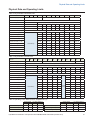
1
Installation, operation and maintenance manual
HydroBank MS
®
Compact, Single Stage Water Source Heat Pumps
½ to 6 Tons – Horizontal and Vertical
MAMM-WSHP-IOM-1MSA (October 2014) - PN 7144926

Contents
Introduction............................................................................................................................3
Nomenclature........................................................................................................................4
General Information...............................................................................................................6
Horizontal Unit Installation....................................................................................................7
Vertical Unit Installation ......................................................................................................10
Discharge Duct Sizing Considerations................................................................................12
Optional Water Side Economizer Piping and Control.........................................................13
Ventilation Air Considerations.............................................................................................14
Electrical Connections ........................................................................................................14
Hot Gas Bypass Option.......................................................................................................15
Hot Gas Reheat Option.......................................................................................................15
Motorized Shutoff Valve Option...........................................................................................16
HP-5 Microprocessor Control..............................................................................................16
Thermostat Wiring...............................................................................................................19
EPiC™ DDC Controls.........................................................................................................22
Cleaning and Flushing the Water System...........................................................................23
Startup.................................................................................................................................24
General Maintenance..........................................................................................................25
Troubleshooting...................................................................................................................26
Physical Data and Operating Limits....................................................................................27
Operating Pressures and Temperatures.............................................................................28
Electrical Data.....................................................................................................................34
Blower Performance Tables................................................................................................38
Typical Wiring Diagrams.....................................................................................................40
Unit Checkout Sheet...........................................................................................................48
2
HydroBank MS Installation and Operation Manual MAMM-WSHP-IOM-1MSA (October 2014)
Introduction
Introduction
This manual provides guidelines for installation, startup,
operation and maintenance of Mammoth HydroBank
vertical and horizontal water source heat pumps.
Installation, startup and operation of this unit must follow accepted industry practices as described in the
ASHRAE Handbook, the National Electric Code, and
other applicable standards. Operate this equipment in
accordance with regulations of authorities having jurisdiction and all applicable codes. Maintenance and service must be performed by qualified personnel familiar
with applicable codes and regulations and experienced
with this type of equipment.
If you have additional questions about the operation or
maintenance of your Mammoth system, contact your
local Mammoth representative. For assistance in locating your Mammoth representative, go to www.mammoth-inc.com and click on the Find a Rep link. Or, call
952-358-6600 or send an email to info@mammoth-inc.
com.
omenclature
Warnings, Cautions and Important Notices
Warnings, cautions and important notices appear at
appropriate locations throughout this manual. Your personal safety and the proper operation of this machine
depend upon the strict observance of these precautions.
Read this manual thoroughly before operating or servicing this unit.
General Warnings
WARNING! Electric shock and moving
equipment hazard. Can cause severe injury
or death. Lock and tag out all electric power
before servicing equipment. More than one
disconnect may be required to de-energize
the unit.
WARNING! The installer must determine
and follow all applicable codes and regulations. This equipment presents hazards of
electricity, rotating parts, sharp edges, heat
and weight. Failure to read and follow these
instructions can result in property damage,
severe personal injury or death.
CAUTION! Installation and servicing of this
equipment should only be undertaken by a
trained professional with experience working
on commercial HVAC systems. Contact your
Mammoth representative for help in installing
this equipment or scheduling service.
CAUTION: Sharp edges on sheet metal, coil
surfaces and fasteners can cause personal
injury. Avoid contact and wear protective
clothing and gloves.
WARNING! Indicates a potentially hazardous situation which, if not avoided, could
result in death or serious injury.
CAUTION! Indicates a potentially hazardous
situation which, if not avoided, could result
in minor or moderate injury. It could also be
used to alert against unsafe practices.
IMPORTANT: Indicates a situation that could result in
equipment or property-only damage.
HydroBank MS Installation and Operation Manual MAMM-WSHP-IOM-1MSA (October 2014)
3
Nomenclature
Nomenclature
1
2
3
4
5 6 7
8
9
M S H 1 0 1 9 D L
Digits 1-2: Model Type
MS = Standard Efficiency
11
E
12
S
13
A
14
C
15
Y
16
1
17 18
0 1
01 = Standard Galvanized
XX = Special
Digit 16: Filtration
Digit 4: Design Series
1 = A Design
Digits 5-7: Nominal Capacity
036 = 36,000
006 = 6,000
040 = 40,000 (Vertical Only)
009 = 9,000
042 = 42,000
012 = 12,000
048 = 48,000
015 = 15,000
060 = 60,000
019 = 19,000
070 = 70,000
024 = 24,000
030 = 30,000
Digit 9: Return Air
L = Left
R = Right
S
Digits 17-18: Cabinet Finish
Digit 3: Cabinet Type
H = Horizontal
V = Vertical
Digit 8: Voltage
A = 115/60/1
D = 208-230/60/1
E = 265-277/60/1
10
F = 208-230/60/3
G = 460/60/3
Digit 10: Discharge Air
T = Top
S = Straight
E = End
1 = Standard 1" w 1" Throwaway
2 = 4-Sided 2" w 1" Throwaway
3 = 4-Sided 2" w Merv8
4 = 4-Sided 2" w Merv13
X = Special
Digit 15: Coil Coating
C = E-Coat
Y = None (standard)
X = Special
Digit 14: Heat Exchanger
C = Copper (standard)
N = Cupro-Nickel
Digit 13: Blower Motor
A = PSC (standard)
C = ECM - Constant Torque
E = ECM - Constant CFM
Digit 12: Application Type
S = Standard Range (standard)
G = Geothermal Range
Digit 11: Controls
E = Stand-Alone
B = BACnet®
L = LONMARK®
M = ModBus®
N = Metasys® N2 by JCI
X = Special
4
HydroBank MS Installation and Operation Manual MAMM-WSHP-IOM-1MSA (October 2014)
Nomenclature
19 20 21
23 23
Y Y Y Y Y
24
25 26
Y M V
27
Y
28 29
0 1
30 31 32
33 34 35 36 37 38
39 40
41
H G B W S E C M R Y Y
Y
42
S
43
44
1 B
Digit 44: Build Type
Digits 19-21: Heating Option
YYY = None (standard)
XXX = Special
A = Stock finish good
B = Configured to order
C = Special build
Digits 22-23: Reserved - Future
Digit 43: Warranty
YY = None (standard)
1 = 1 Yr Delayed Startup Ext Warranty
2 = 2nd Yr Refrig Circuit Parts
3 = 2nd Yr Complete Unit Parts
4 = 2-5 Yr Compressor Only
5 = 2-5 Yr Refrigerant Circuit Parts
6 = 2-5 Yr Complete Unit Parts
Y = Standard Factory Warranty
X = Special
Digit 24: Heat Recovery
Y = None (standard)
Digits 25-26: Fluid Flow Control
MV = 2-way Motorized Valve
YY = None (standard)
XX = Special
Digit 27: Sound Options
Digit 42: Condensate Pan
S = Galvanized Steel
T = Stainless Steel
C = Compressor Blanket
Y = None (standard)
Digit 28-29: Cabinet Insulation
01 = Standard 1/2" Dual Density Fiberglass
02 = 1/2" Closed Cell Foam (IAQ)
XX = Special
Digit 41: Switching Devices
A = Unit Disconnect Switch
B = Water Differential Pressure Switch (DPS)
C = Dirty Filter Switch
D = Combo - Disconnect & Dirty Filter Switch
E = Combo - Disconnect & Diff Pressure Switch
F = Combo - Disconnect, Diff Pressure, Filter
G = Combo - Differential Pressure & Dirty Filter
Y = None (standard)
X = Special
Digits 30-32: Refrigerant Circuit Options
HGB = Hot Gas Bypass
HGR = Hot Gas Reheat
YYY = None (standard)
XXX = Special
Digits 33-35: Water Side Economizer
WSE = Water Side Economizer
YYY = None (standard)
XXX = Special
Digits 39-40: Reserved - Future
YY = None
Digits 36-38: Monitoring Devices
CMR = Compressor Monitor Relay
BMR = Blower Monitor Relay
PHM = Phase Monitor Device
CBR = Compressor & Blower Monitor Relays
CPM = Compressor & Phase Monitor
BPM = Blower & Phase Monitor
CBP = Compressor, Blower & Phase Monitor
YYY = None (standard)
XXX = Special
HydroBank MS Installation and Operation Manual MAMM-WSHP-IOM-1MSA (October 2014)
5
General Information
General Information
Receiving Inspection
Unit Protection
When receiving equipment, check the Bill of Lading to
verify that all crates and cartons have been received.
Compare shipped-loose items received against the list
provided. Check for damage. Claims for loss or damage
must be made with the carrier.
Keep units covered during construction to protect components from dust and other harmful material. Cap the
ends of all open pipes. This is critical while spraying
fireproofing material on bar joists, sandblasting, spray
painting and plastering. Physical damage or contamination may prevent unit startup and result in costly
cleanup.
IMPORTANT: This product was carefully packed
and thoroughly inspected before leaving the factory.
Responsibility for its safe delivery was assumed
by the carrier upon acceptance of the shipment.
Claims for loss or damage sustained in transit must
therefore be made upon the carrier as follows. Take
detailed photos for documentation.
Visible Loss or Damage
If there is any external evidence of loss or damage,
refuse delivery of the damaged item. Refusal of
items must be noted on the freight bill or carrier’s
receipt, and signed by the carrier’s agent. Failure to
adequately describe such external evidence of loss
or damage may result in the carrier’s refusal to honor
a damage claim.
IMPORTANT: To prevent equipment damage, units
should not be operated for supplementary heating
and cooling during the construction period.
Pre-installation Checklist
•
Inspect the unit for any specific tagging numbers
indicated by the factory per a request from the
installing contractor.
•
Check the unit nameplate for the size and voltage
rating and confirm against the plans that the unit is
being installed in the correct location.
IMPORTANT: Check the unit name plate for correct
voltage with the plans before installing the equipment. Make sure all electrical connections are made
in accordance with national (NEC) and local codes.
Concealed Loss or Damage
Concealed loss or damage means loss or damage
which does not become apparent until the product
has been unpacked. When the damage is discovered, make a written request for inspection by the
carrier’s agent within fifteen (15) days of the delivery
date and file a claim with the carrier,
Storage
Equipment should be stored in its original packaging.
Temporary storage at the job site must be indoors, completely sheltered from rain, snow, etc. High or low temperatures naturally associated with weather patterns will
not harm units. Excessively high temperatures, 140°F
(60°C) and higher, may deteriorate certain plastic materials and cause permanent damage. Keep units upright.
•
Verify the installation location with the piping, sheet
metal and electrical contractors prior to installation.
•
Verify all clearances are available for the unit prior
to installation.
•
Note the location and routing of water piping, condensate drain piping, and electrical wiring. The locations of these items should be clearly marked on the
unit submittal drawings.
IMPORTANT: Remove the shipping block from the
blower housing opening before starting the unit! See
figure below. Failure to do so may result in poor
blower operation or motor failure.
IMPORTANT: Operating a unit after it has been
stored or transported on its side can result in serious compressor damage which is not covered under
the equipment warranty. Make sure the unit is first
returned to its normal upright position for at least 24
hours before operating.
6
HydroBank MS Installation and Operation Manual MAMM-WSHP-IOM-1MSA (October 2014)
Horizontal Unit Installation
Horizontal Unit Installation
Unit Location
Do not locate units above noise-sensitive areas such
as offices, meeting rooms, and classrooms. If possible,
avoid locations above areas where there is considerable
traffic as service time may be limited during occupied
hours. Placing units above hallways is a typical location
in schools to avoid potential noise problems, with supply and return air ducted to adjacent classrooms. Such
locations may limit service time during school hours.
IMPORTANT: This equipment is designed for indoor
installation only. Sheltered locations such as attics,
garages, etc., generally will not provide sufficient
protection against extremes in temperature and/or
humidity, and equipment performance, reliability,
and service life may be adversely affected.
Suggested Clearances
Units should be positioned to provide clearance to perform routine maintenance or service, including easy filter
replacement. Figure 1 shows suggested clearances. Any
additional clearances would be beneficial, but are not
always necessary. The requirements on any specific unit
may increase or decrease depending on factors such as
electrical installation codes. If return air is not ducted, be
sure to provide enough clearance for adequate airflow.
Figure 1: Suggested Horizontal Unit Clearances
2 ft (61 cm)
motor
access end
discharge
2 ft (61 cm)
motor access
straight
discharge
2 ft (61 cm)
service access
filter removal
(width of filter)
Mounting
Horizontal units are typically suspended from the
ceiling using four 3/8 inch threaded rods (supplied
by others). The rods should be attached to building
structural members. Slide the rods through the mounting
brackets and rubber isolators provided on each corner
of the unit. The mounts can be repositioned from the
end to the side of the unit to accommodate installation
requirements. See “Repositioning Mounting Brackets”
on page 8.
Connect the rods to the mounts using a fender washer
and double hex nuts. The fender washer should cover
the entire bottom of the rubber isolator. See Figure
2. When installed, the unit should be slightly pitched
toward the condensate drain connection.
Figure 2: Typical Horizontal Unit Installation
Unit power disconnect (by others)
Flexible high-pressure hoses with swivel
fittings (by others)
Low voltage thermostat or controls wiring
Line voltage power wiring
Flexible duct
connector
(by others)
3/8 threaded rod (by others)
Condensate drain
with trap (by others)
Fender washer (by others)
HydroBank MS Installation and Operation Manual MAMM-WSHP-IOM-1MSA (October 2014)
Rubber isolators (supplied)
Double hex nuts (by others)
7
Horizontal Unit Installation
Repositioning Mounting Brackets
Horizontal unit mounting brackets can be repositioned
from the end to the side of the unit as needed to accommodate installation requirements, as follows.
14. Rotate the assembly 180 degrees and turn it 90
degrees, as shown in Figure 4.
1. Raise and support the corner of the unit to provide
access to the mounting bracket.
2. Carefully pry the rubber isolator out of the bracket.
3. The mounting bracket is held in place with two sheet
metal screws and one mounting bolt. Remove all
three fasteners and set aside for reassembly.
15. Slide the assembly into the slot from which you
removed the access panel.
16. Verify that, in its new configuration, the orifice ring
on the blower motor faces the access opening on
the side or end of the unit.
17. Reconnect the wiring to the motor.
18. Slide the access panel into its new location on the
side or end of the unit.
4. Move the mounting bracket from the end to the side
of the unit, or vice-versa (see Figure 3).
19. Reinstall the unit top, using the sheet metal screws
removed earlier.
5. Screw the center mounting bolt into the provided
connector and finger-tighten.
Figure 4: Field Conversion of Air Discharge
6. Align the mounting bracket with the unit and screw
in the sheet metal screws in the holes provided.
7. Tighten the center mounting bolt to 17 ft-lbs.
8. Remount the rubber isolator in the mounting bracket.
Figure 3: Repositioning Mounting Brackets
Piping
Field Conversion of Air Discharge
The blower on horizontal units can be field-converted
from straight to end discharge or vice-versa as needed
to meet application requirements, as follows.
WARNING! Electric shock and moving
equipment hazard. Can cause severe injury
or death. Lock and tag out all electric power
to the unit before beginning.
9. Remove the sheet metal screws securing the unit
top and set aside for reassembly.
10. Remove the top from the unit and set aside.
11. Slide out the access panel from the end of the unit
on straight discharge units and from the side of the
unit on end discharge units.
12. Disconnect the electrical wiring from the motor.
13. Slide the blower housing and motor assembly vertically upward and out of the unit.
8
Heat pumps are typically connected to supply and return
piping in a two-pipe, reverse-return configuration, which is
inherently self-balancing. It also requires only trim-balancing where multiple heat pumps with different flow and pressure drop characteristics exist in the same loop.
Supply and return run-outs usually join the heat pump via
short lengths of high-pressure, flexible hose which serve
as sound attenuators for both heat pump operating noise
and hydronic pumping noise. One end of the hose should
have a swivel fitting to facilitate removal for service. Make
sure that threaded fittings are sealed. Teflon tape can be
used to provide a tight seal.
Hard piping is not recommended since it does not
provide vibration or noise attenuation. If used, it must
include a union to facilitate heat pump removal. Avoid
dissimilar metal fittings as they may corrode. If unavoidable, use dielectric isolation at the connection point.
Supply and return shutoff valves are required at each
heat pump. The return valve may be used for balancing.
It should have a “memory stop” so that it can always be
closed off but can only be reopened to the proper position
for the flow required.
HydroBank MS Installation and Operation Manual MAMM-WSHP-IOM-1MSA (October 2014)
Horizontal Unit Installation
No heat pump should be connected to the supply and
return piping until the water system has been cleaned and
flushed completely. See”Cleaning and Flushing the Water
System” on page 23.
Check for proper water balance by measuring the differential temperature reading across the water connections. To
ensure proper water flow, it should be between 10°F and
14°F for heat pumps in the cooling mode.
Condensate Drain Piping
A flush-mounted drain connection is provided on the outside of horizontal cabinets, on the end opposite the water
line connections. Condensate piping can be PVC, steel or
copper. PVC typically eliminates the need to insulate the
pipe to prevent sweating.
A condensate trap that has a depth of at least 3 inches
or 2.5 times the expected negative static pressure of the
unit must be provided. The condensate pipe run must
slope away from all units at least 1/8 inch per foot. The
trap may be constructed of PVC, copper or steel. Piping
should be vented, with the vent after the trap. See Figure 5 below for an example. Refer to local codes for the
correct condensate piping to drains.
Figure 5: Vented PVC Condensate Trap by Others
Ductwork and Sound Attenuation
Horizontal, ceiling-mounted heat pumps virtually always
have discharge ductwork attached to the unit. A collar
is provided on the discharge to facilitate attachment to
the ductwork. Ductwork should conform to industry standards. See Figure 6 below and “Discharge Duct Sizing
Considerations” on page 12.
Good design practice requires a flexible connector
between the collar and transition to the main duct system. This connector attenuates sound from the unit,
especially fan sound, and simplifies unit removal.
Ductwork should be lined with an acoustic, thermal insulation that is a minimum of ½ inch thick. For sensitive
installations, use 1-inch insulation a minimum of five to
10 feet prior to each diffuser. For applications that are
especially acoustically sensitive, consider an acoustic kit
that includes additional unit lining and dampening material beneath the entire unit.
Ducted returns may be used on horizontal units for
acoustically sensitive applications. Return ducting
should extend at least 12 inches from the coil before
transitioning to provide even air distribution across the
coil. A flexible connector should be used to connect the
unit to the return ducting to attenuate unit sound levels
and allow ease of unit removal. The filter section is supplied with a bracket to accommodate return ductwork.
Changes in duct direction and internal devices such as
dampers that create airflow turbulence can increase
acoustic problems. Minimize these items where possible. Placing a straight run of duct between fittings will
decrease turbulence and associated noise. Diffusers
located in the bottom of a trunk duct pose acoustical
problems. Volume control dampers should be placed well
upstream of any air outlets.
Figure 6: ASHRAE AND SMACNA Suggested Supply and Return Air Ducting
Return air located
away from unit fan
Two 90 degree turns
prior to intake
Flexible connectors
Acoustic
thermal lining
Ductwork supported
independently from unit
HydroBank MS Installation and Operation Manual MAMM-WSHP-IOM-1MSA (October 2014)
9
Vertical Unit Installation
Vertical Unit Installation
Figure 7: Suggested Vertical Unit Clearances
Location
Vertical units are typically installed in a small mechanical
room or closet, with discharge ductwork routed overhead
into the conditioned space. See Figure 8. Return air may
be ducted or non-ducted. If non-ducted, provision must be
made for return air to freely enter the mechanical room.
This is often accomplished by using a louvered door at the
entrance. A sound baffle may be needed on the door to
attentuate noise from the unit.
IMPORTANT: This equipment is designed for indoor
installation only. Sheltered locations such as attics,
garages, etc., generally will not provide sufficient
protection against extremes in temperature and/or
humidity, and equipment performance, reliability,
and service life may be adversely affected.
Install the unit on a rubber or neoprene mounting pad
for sound isolation. The pad should be at least 3/8 inch
thick.
Suggested Service Clearances
Figure 7 shows minimum suggested clearances. Any
additional clearances would be beneficial, but not
always necessary. Units need to be accessed from
the front to change the filter and to access the electrical panel, blower motor, air coil and compressor compartment. The requirements on any specific unit may
increase or be reduced depending on several factors
such as maintenance requirements and mechanical or
electrical installation codes.
1 ft (31 cm)
non-ducted
units for
even air
distribution
across coil
2 ft (61 cm)
service access
filter removal
(width of filter)
Piping
Heat pumps are typically connected to supply and return
piping in a two-pipe, reverse-return configuration, which is
inherently self-balancing. It also requires only trim-balancing where multiple heat pumps with different flow and pressure drop characteristics exist in the same loop.
Supply and return run-outs usually join the heat pump via
short lengths of high-pressure, flexible hose which serve
as sound attenuators for both heat pump operating noise
and hydraulic pumping noise. One end of the hose should
have a swivel fitting to facilitate removal for service. Make
sure that threaded fittings are sealed. Teflon tape can be
used to provide a tight seal.
For geothermal applications, all water lines and valves
should be insulated to prevent condensation.
Figure 8: Typical Vertical Unit Mounting
Unit power disconnect
(by others)
Flexible duct connectors
(by others)
Flexible, high-pressure
hoses with swivel fittings
(by others)
Condensate drain pipe with
vent by others (vertical
units are internally trapped)
Ducted return (where used)
Filter removal
Low voltage thermostat
or controls wiring
Line voltage power wiring
Isolation pad (by others)
10
HydroBank MS Installation and Operation Manual MAMM-WSHP-IOM-1MSA (October 2014)
Vertical Unit Installation
The piping may be steel, copper, or PVC. Avoid dissimilar
metal fittings as they may corrode. If the use of dissimilar
metals is unavoidable, use dielectric isolation at that connection point.
Supply and return run-outs usually join the heat pump
via short lengths of high-pressure flexible hose which are
sound attenuators for both heat pump operating noise and
hydraulic pumping noise. One end of the hose should have
a swivel fitting to facilitate removal for service.
not locate any point in the drain system above the drain
connection of any unit.
The condensate piping system must be vented at its
highest point. Refer to local codes for the correct condensate piping to drains.
Figure 9: Vented PVC Drain Piping By Others
Hard piping is not recommended since it does not
provide vibration or noise attenuation. If used, it must
include a union to facilitate heat pump removal. Avoid
dissimilar metal fittings as they may corrode. If unavoidable, use dielectric isolation at the connection point.
Supply and return shutoff valves are required at each
heat pump. The return valve may be used for balancing.
It should have a “memory stop” so that it can always be
closed off but can only be reopened to the proper position
for the flow required.
IMPORTANT: No heat pump should be connected to
the supply and return piping until the water system has
been cleaned and flushed completely. See”Cleaning
and Flushing the Water System” on page 23.
Check for proper water balance by measuring the differential temperature reading across the water connections. To
ensure proper water flow, it should be between 10°F and
14°F for heat pumps in the cooling mode.
Condensate Drain Piping
Condensate lines on vertical units are internally trapped.
A flush-mounted condensate drain connection is provided on the outside of the cabinet. Condensate piping
can be PVC, steel or copper. PVC typically eliminates
the need to insulate the pipe to prevent sweating. Do
Ductwork and Sound Attenuation
Vertical unit discharge ductwork should include a noninsulated transition from the unit connection to a flexible
connector at the full duct size. It should also include a
short run of duct and an elbow internally lined with insulation but without turning vanes. The main duct may tee
into branch circuits with discharge diffusers. Ductwork
should conform to industry standards. See Figure 10
below and “Discharge Duct Sizing Considerations” on
page 12.
Ductwork should be lined with an acoustic, thermal insulation that is a minimum of ½ inch thick. For sensitive
installations, use 1-inch insulation a minimum of five to
10 feet prior to each diffuser. For applications that are
especially acoustically sensitive, consider an acoustic kit
that includes additional unit lining and dampening material beneath the entire unit.
Figure 10: ASHRAE AND SMACNA Suggested Supply and Return Air Ducting
Acoustic
thermal lining
Return air located
away from unit fan
Two 90 degree turns
prior to intake
Ductwork supported
independently from unit
Flexible connectors
HydroBank MS Installation and Operation Manual MAMM-WSHP-IOM-1MSA (October 2014)
11
Discharge Duct Sizing Considerations
The return air may be ducted or non-ducted. If it is nonducted, provisions must be made for return air to freely
enter the space, through a louvered door for example.
A sound baffle may be needed on the door to attentuate
noise from the unit. For non-ducted applications, a clearance in front of the unit of at least 12” is suggested to
provide even air distribution across the air coil.
Return air ductwork, where used, should be internally lined
with acoustic insulation and include a flexible connector
at the unit. Sound attenuation is particularly critical at the
unit return. The filter section on all units is supplied with a
bracket to accommodate return ductwork.
Discharge Duct Sizing Considerations
In order to generate full airflow on forward curve fans
like those used in HydroBank units, it is essential that
the discharge duct have approximately 2.5 fan diameters of straight duct to develop full airflow. This duct
should be free of turns, tees, sudden expansions or
contractions, etc. Failure to provide this transition ductwork can significantly reduce the maximum flow that the
blower can deliver. See Figure 11 to the right.
Figure 11: Controlled diffusion and establishment of a
uniform velocity profile in a straight length of outlet duct
AMCA Standard 210 specifies an outlet duct that is not
greater than 107.5% nor less than 87.5% of the fan outlet area. It also requires that the slope of the transition
elements not be greater than 15% for converging elements, or greater than 7% for diverging elements.
Suggested discharge ductwork sizing for HydroBank
units based on these recommendations is provided in
Table 1 and Table 2 to the right.
All Mammoth units are tested for airflow as part of our
ISO/ARI certification program. It is possible to have
airflow that is above or below design requirements for
many reasons. The first step in evaluating and correcting air flow rates is to compare the catalog fan performance to the measured external static pressures and
airflow.
Possible corrections for too much airflow include:
•
Change the blower motor to a lower speed.
•
Add static to the system. A thicker filter is an easy
option.
Possible corrections for not enough airflow include:
•
Change the blower motor to a higher speed.
•
Remove static from the system by replacing dirty
filters.
•
Check the ductwork for common design or installation problems.
Table 1: Horizontal unit discharge duct sizing - inches
Unit Size
Minimum
Straight
Discharge
Maximum Duct
Minimum Duct
Width
Width
006 - 012
12.5
8.6
9.7
7.0
7.9
015 - 024
22.5
10.5
14.0
8.5
11.4
Height
Height
030
25.0
10.5
14.0
8.5
11.4
036 - 042
25.0
11.8
17.2
9.6
14.0
048 - 070
25.0
14.5
17.2
11.8
14.0
Table 2: Vertical unit discharge duct sizing - inches
Unit Size
Minimum
Straight
Discharge
Maximum Duct
Minimum Duct
Width
Height
Width
Height
006 - 012
12.5
9.7
9.7
7.9
7.9
015 - 024
22.5
15.1
15.1
12.3
12.3
030 - 042
25.0
15.1
15.1
12.3
12.3
048 - 070
25.0
19.4
17.2
15.8
14.0
More detailed information including suggestions for correcting airflow problems can be found in the AMCA Fan
Application Manual.
12
HydroBank MS Installation and Operation Manual MAMM-WSHP-IOM-1MSA (October 2014)
Ventilation Air Considerations
Ventilation Air Considerations
Outside air may be required for ventilation. Refer to
local codes. The temperature of the ventilation air must
be controlled so that the mixture of outside air and
return air entering the unit is within application limits. It
is recommended that the ventilation air inlet be closed
during unoccupied periods (i.e. night setback).
The ventilation air system is typically a separate building subsystem with its own distribution ductwork. Simple
introduction of the outside air into each return air plenum chamber is recommended, reasonably close to the
unit air inlet. Do not duct outside air directly to the unit
inlet. Provide sufficient distance for the thorough mixing
of outside and return air.
Electrical Connections
All field installed wiring must comply with all local and
national electrical codes. See “Electrical Data” starting
on page 34 for applicable fuse or breaker sizes. Consult the wiring diagram provided with your unit for the
field connections required.
WARNING! Electric shock and moving
equipment hazard. Can cause severe injury
or death. Lock and tag out all electric power
during installation.
On units equpped with the non-fused disconnect option,
power wiring is brought in the through the knockout in
the top of the junction box. See Figure 14.
Figure 14: Non-Fused Disconnect Electrical Connections
Horizontal Unit
Field control
wiring
Wiring to the unit is routed through the electrical knockouts in the front corner of the unit. See Figure 12 and
Figure 13. For detailed information on knockout locations and sizes, see the dimensional drawings provided
with your unit submittal package.
Figure 12: Horizontal Unit Electrical Connections
Power wiring
Vertical Unit
Field control
wiring
Power wiring
Field control
wiring
Power wiring
Operating Voltage
Figure 13: Vertical Unit Electrical Connections
Field control
wiring
Incoming power supply must comply with the data in
Table 3. Unit operation outside of the minimum or maximum range is not recommended and will result in premature component failure.
IMPORTANT! Units operating with over- or undervoltage conditions for extended periods of time will
experience premature component failure. Threephase system imbalance should not exceed 2%.
Table 3: Operating voltages
Power
wiring
Minimum
Maximum
208-230/60/3
197 volts
253 volts
460/60/3
414 volts
506 volts
380-415/50/3
342 volts
418 volts
575/60/3
515 volts
632 volts
HydroBank MS Installation and Operation Manual MAMM-WSHP-IOM-1MSA (October 2014)
13
Optional Water Side Economizer Piping and Control
Optional Water Side Economizer Piping and Control
The waterside economizer option (WSE) allows precooling of the entering air to take advantage of cool
loop fluid and to reduce compressor operation during
cool weather. Water lines and condensate drain lines are
attached to the unit as shown in Figure 16. All water lines
and valves should be insulated to prevent condensation.
The condensate drain for the WSE coil must be trapped
(the unit drain is internally trapped).
Each waterside economizer includes a water-to-air coil, a
3-way water diverting valve, an aquastat (water temperature switch), a relay and interconnecting wiring to the unit
controls box. The aquastat is factory set at 65°F. It is field
adjustable from 45° to 75°F. See Figure 16 for the location of the access panel to adjust the switch.
Control Sequence with One-Stage Thermostat
On a call for cooling, the 3-way diverting valve opens
for economizer cooling if the entering water temperature
is below the set point of the aquastat. If it is above the
aquastat set point, the compressor is automatically energized for mechanical cooling.
Control Sequence with Two-Stage Thermostat
On a call from the thermostat for stage-one cooling, the
3-way diverting valve opens for economizer cooling if
the entering water temperature is below the set point of
the aquastat. If it is above the aquastat set point, the
compressor is energized for mechanical cooling.
On a call for stage-two cooling, the compressor starts
for simultaneous compressor and economizer cooling. If
the entering water temperature rises above the aquastat
set point, the 3-way valve closes to stop economizer
cooling and the compressor remains energized for
mechanical cooling.
Figure 15: Water Side Economizer Wiring Diagram
Figure 16: Water Side Economizer Piping
Horizontal Unit
Vertical Unit
Water out to unit
Access panel for water
temp switch (aquastat)
Water in from loop
Unit condensate drain
Water out to loop
Water in from WSE
Water in from WSE
Water out to loop
14
Unit and WSE
condensate drains
WSE condensate drain
(with trap)
HydroBank MS Installation and Operation Manual MAMM-WSHP-IOM-1MSA (October 2014)
Hot Gas Bypass Option
Hot Gas Bypass Option
Hot gas bypass prevents frosting of the evaporator coil
during low-load conditions by keeping the compressor
more fully-loaded. Hot, high-pressure refrigerant gas is
diverted to the low-pressure suction side to help stabilize the system balance point. This option includes a hot
gas bypass valve.
Hot gas bypass to low-pressure line
Hot gas bypass valve
Hot Gas Reheat Option
Hot gas reheat is the ideal solution to prevent overcooling of the occupied space when the unit is in dehumidification mode. Hot gas is used to reheat saturated
air coming off the cooling coil without using an external
heat source.
NOTE: This option requires that a field-supplied humidistat be connected to the R and H terminals on the terminal block located inside the control panel. See the wiring
diagram below.
Hot gas reheat coil
Hot gas reheat valve
Figure 17: Hot Gas Reheat Wiring
HydroBank MS Installation and Operation Manual MAMM-WSHP-IOM-1MSA (October 2014)
15
Motorized Shutoff Valve Option
Motorized Shutoff Valve Option
The motorized valve option is typically used in systems
that employ VFDs on the condenser water pumps.
When the space temperature set point is satisfied, the
unit shuts down and the valve closes. Pump power is
thus greatly reduced at reduced flows, resulting in significant energy savings.
The motorized valve shuts off the water flow through the
unit when the compressor is off. The valve is a normally
open, power-close type and will open in the event of
power loss.
Figure 18: Motorized Valve Option
HP-5 Microprocessor Control
Features
•
Low and high voltage protection.
•
Check microprocessor at startup – self-diagnostic
•
Random start time delay from 5 to 35 seconds
•
Compressor anti-short cycle protection for 300 seconds (5 minutes)
•
Compressor, fan and reversing valve control
•
Condensate overflow protection
•
Compressor lockout with selectable intelligent/
manual reset
•
LED status on the board
•
Lockout alarm signal to an LED in the wall thermostat in the event of a safety circuit fault
•
Fan interlock to automatically energize the fan
whenever the compressor is on
•
Board operable on 50 and 60 cycle power
•
Emergency shutdown from a field-supplied signal
•
Unoccupied (night setback and night setup) mode
from a field-supplied signal.
•
Dry contact alarm signal for connection of a fault
signal to a DDC controller.
•
Auxiliary dry contact for tie-in of a motorized valve
when the compressor is on (or optional compressor
status)
•
Night heating or cooling operation from the wall
thermostat (compatible Mammoth thermostat
required)
•
Override of the unoccupied mode from the thermostat for 2 hours (compatible Mammoth thermostat
required)
16
•
Low and high pressure compressor protection
•
Low pressure bypass with 0, 1, 2 and 3 minute
selections.
Operation
INITIAL POWER-UP: When power is applied to the controller from unit’s 24-volt transformer, a “green” LED will
be illuminated and a 120 second time delay will occur
before the fan, reversing valve and compressor are able
to operate. The controller will perform a self-diagnostic
and voltage check.
Figure 19: HP-5 Microprocessor Board
LOSS OF POWER: On a loss of 24-volt power to the
board, all the outputs are de-activated. On return of
power, a 120 second time delay will occur before the
fan, reversing valve and compressor are able to operate. After 120 seconds, the fan, reversing valve and
compressor are able to operate after a short time delay.
HydroBank MS Installation and Operation Manual MAMM-WSHP-IOM-1MSA (October 2014)
HP-5 Microprocessor Control
RANDOM START: A 5 to 35 second time delay of fan,
reversing valve and compressor operation will occur
each time the unit comes off shutdown mode, unoccupied mode and low/high voltage mode. The random
start time varies each time it is activated; for example,
the time delay may be 5 seconds, then 12, then 30, then
17, then 32, then 6, etc.
Note: The following descriptions assume Initial Powerup and Random Start functions have occurred.
FAN OPERATION: On a call for fan operation from the
wall thermostat “fan on” switch or from a call for compressor operation, fan operation is delayed for 2 seconds.
REVERSING VALVE: On a call for cooling from the
wall thermostat, the reversing valve is energized after
4 seconds. Once the cooling demand is satisfied, the
reversing valve is held on for 4 seconds before it is deenergized.
COMPRESSOR OPERATION: On a call for cooling
or heating from the wall thermostat, the compressor is
energized from the compressor output terminal after 6
seconds. Once the call for cooling or heating is satisfied, the compressor shuts off immediately. At that time,
a 300 second (5 minute) timer begins to prevent the
compressor from re-starting even though the wall thermostat may again call for cooling or heating. During this
300 second interval, the compressor will not be allowed
to restart. After the 300 second time delay elapses, the
compressor is allowed to start if the wall thermostat calls
for cooling or heating.
FAN INTERLOCK OPERATION: When compressor
operation is required, the fan is automatically enabled 4
seconds before the compressor, even if the wall thermostat is not calling for fan operation. This makes sure the
fan will be on whenever the compressor is on.
SAFETY CIRCUIT OPERATION: The unit has up to 4
safety circuits to prevent the compressor from operating
during abnormal conditions.
•
High Pressure Switch: If the refrigerant pressure
exceeds the high pressure set-point, the high pressure switch opens immediately and the unit goes
into the lockout mode
•
Low Pressure Switch: If the refrigerant pressure falls
below the low pressure set-point, the low pressure
switch closes immediately and the unit goes into
the lockout mode after the amount of low pressure
bypass has been satisfied.
•
Optional Freezestat Switch: If the leaving fluid temperature falls to 32°F, the freezestat switch opens.
After 10 seconds, the unit goes into lockout mode.
•
Condensate Overflow Protection: If the drain pan
sensor comes in contact with moisture for more than
30 seconds, the unit goes into lockout mode.
LED STATUS:
•
ON
Normal operating mode
•
1 Flash
High pressure fault
•
2 Flashes Emergency shutdown mode
•
3 Flashes Freezestat switch
•
4 Flashes Condensate overflow fault
•
5 Flashes Low voltage fault
•
6 Flashes High voltage fault
•
7 Flashes Low pressure fault
LOCKOUT MODE: Lockout mode will occur if any of the
safety circuits are activated. In this condition the compressor is de-energized, but the fan operates if the wall
thermostat is calling for cooling or heating. The two lockout alarm circuits are also enabled.
LOW AND HIGH VOLTAGE PROTECTION: If voltage
conditions are good, the unit performs a self-diagnostic
check for faults. If no faults are identified, the “green”
LED comes on with no flashes. If the supply voltage
falls below the minimum or above the maximum, the
reversing valve, fan and compressor are de-energized.
LED lights will indicate the fault. Once the voltage falls
within an acceptable range, the unit will restart without
requiring a reset. All time delays required for start-up of
the fan, compressor and reversing valve will take place
before the unit is re-started. The low voltage cut-out is
21.6 VAC and the cut-in is 24.0 VAC. The high voltage
cut-out is 34.0 VAC and the cut-in is 29.7 VAC. These
high and low voltages are monitored at terminals “R”
and “COM”.
LOCKOUT ALARM (CIRCUIT) SIGNAL: This is the first
lockout alarm circuit. In the lockout mode, the circuit
provides a 24-volt power (+) signal at the “LO ALM” terminal of the terminal block which is wired to the LED on
the wall thermostat to indicate a lockout condition.
DRY CONTACTS LOCKOUT ALARM (CIRCUIT) SIGNAL: This is the second lockout alarm circuit. In the
lockout mode, this circuit provides a signal at the terminal block. The signal is a set of normally open contacts
at terminals “IN ALM” and “OUT ALM” of the unit terminal strip. The contacts close in the lockout mode, allowing connection of a remote alarm.
RESET OF A LOCKOUT: The controller can be selected
to manual or intelligent reset of a lockout mode through
an on-board dip switch labeled as “RST”. When a manual reset is selected, the unit stays in lockout until it is
manually reset by interrupting power or by removing the
HydroBank MS Installation and Operation Manual MAMM-WSHP-IOM-1MSA (October 2014)
17
HP-5 Microprocessor Control
call for mechanical heating or cooling. Intelligent reset
automatically terminates the lockout mode 5 minutes
after a lockout condition occurs. The purpose of intelligent reset is to allow the unit to attempt to reset itself
if the condition that caused the original lockout corrects
itself. After 3 attempts in a 6000 second (100 minute)
period after the first lockout, the intelligent reset feature
is terminated and the unit stays in lockout until the unit
is manually reset. The number of reset attempts is limited to protect the unit from severe damage.
OVERRIDE: The override feature is available with the
wall thermostat and is activated by the push button on
the face of the wall thermostat (see Figure 3). When
pushed, the unit will switch back to its normal occupied
temperature set points on the wall thermostat for 2
hours. After 2 hours, the unit will resume its unoccupied
mode operation until the unoccupied mode signal is
removed from terminals “COM” and “NS”. The push button is only operable when the unit is in the unoccupied
mode.
EMERGENCY SHUTDOWN MODE: Emergency shutdown allows the unit to be made inoperable via a
remote signal. The emergency shutdown mode can be
activated in two ways:
•
By closing the circuit between terminals “COM”
and “ESD” via a field supplied set of contacts (see
Figure 4).
•
By supplying 24 volts to terminals “COM” and
“ESD”.
In shutdown mode, the reversing valve, fan and compressor are inoperable, the lockout alarm circuits are
activated and the green LED flashes repeatedly 2 times
(quick ON and one long OFF). The unit does not need
to be reset. The signal at terminals “COM” and “ESD”
can be “daisy-chained” between many units. When the
signal to terminals “COM” and “ESO” is removed, the
random start timing function is activated.
AUXILIARY DRY CONTACTS: A pair of normally open
contacts at terminals “DRC IN” and “DRC OUT” shall
close and a pair of normally closed contacts at terminals “DRC IN” and “DRC OUT” shall open when the
compressor is energized. This will allow connection of
24-volt power to the normally closed contacts to supply
power to a normally open (powered close) motorized
valve when the compressor is on.
TEST PIN JUMPER: An on-board pair of male terminals provides for an optional mode of operation which
defeats both forms of compressor time delays. If a hardwired jumper is placed across the “TEST” and “TEST
IN” terminals, the random start time delay and the
compressor’s five minutes of anti-short cycle time delay
will be ignored. However, the two, four and six second
18
time delays on the fan, reversing valve and compressor
remain in place.
LOW PRESSURE BYPASS: The dip switches labeled
“DY1” and “DY2” allow for four different amounts of low
pressure switch bypass: zero, one, two and 3 minutes.
The low pressure bypass timer logic occurs anytime the
board senses a low pressure switch fault.
Testing
FIELD TEST MODE: If the two ‘TEST” quick connect
terminals are connected, there will be no random start
delay, no anti-short cycle delay, and no power to delay
present. The normal fan, reversing valve, and compressor on delays of two, four, and six seconds will still be
present, as well as the four second reversing off delay.
FACTORY TEST MODE: The factory mode is entered
by applying the correct combination of inputs to the
control at power up. The factory test mode operates the
control by associating control outputs with inputs. The
factory test mode is automatically canceled 30 seconds
after control power up and may not be run again until
power is removed from the control.
•
Factory Test Mode Initiation: The control checks
the control inputs during the first 1.0 seconds after
power up, looking for the factory speedup input
combination. To initiate the factory lest mode, at
some point during the first 1.0 seconds after power
up, the high pressure switch input must be active,
the “SENSOR” input must have 470 kΩ connected,
the two “TEST” quick-connect terminals connected,
voltage source must be between 22 to 29 VAC, and
all of the other inputs must be inactive.
•
Factory Test Mode Operation: While in the factory
test mode, the following combinations of inputs will
result in the operation of the corresponding output
conditions:
o LED stays active.
o “O” thermostat input active and night setback
input inactive - Reversing valve output active.
o “G” thermostat input active and emergency
shutdown input inactive - Fan output active.
o “Y” thermostat input active and high pressure
switch input active - Compressor output active.
o Thermostat night setback input active and override input inactive - Alarm output active.
HydroBank MS Installation and Operation Manual MAMM-WSHP-IOM-1MSA (October 2014)
Thermostat Wiring
Thermostat Wiring
The HP-5 microprocessor control is designed to operate
with wall thermostats sold by Mammoth. It can be used
with other heat pump thermostats but some features
may not be available. Wiring from the thermostat is routed through an electrical knockout in the front of the unit.
See Figure 12 and Figure 13 on page 13. A removable terminal block simplifies hookup. See Figure 20.
To remove it, gently pull it straight out from the control
board. Thermostat connections are made as described
in the following diagrams.
Figure 20: HP-5 Controller
Fixed 8-Pole Terminal Block (P2)
Removable 8-Pole Terminal Block (P1)
Figure 21: Thermostat Wiring With Night Setback/Night Setup and Emergency Shutdown
HydroBank MS Installation and Operation Manual MAMM-WSHP-IOM-1MSA (October 2014)
19
Thermostat Wiring
Figure 22: Thermostat Wiring With Override and Night Setback
Figure 23: Thermostat Wiring - Emergency Shutdown Mode With Override
20
HydroBank MS Installation and Operation Manual MAMM-WSHP-IOM-1MSA (October 2014)
Thermostat Wiring
Figure 24: Thermostat Wiring - Emergency Shutdown Mode Without Override
HydroBank MS Installation and Operation Manual MAMM-WSHP-IOM-1MSA (October 2014)
21
EPiC™ DDC Controls
EPiC™ DDC Controls
As an option, Mammoth offers factory-programmed
and unit-mounted EPiC DDC controllers for precise unit
operation. They are factory programmed per the application, and have a 16-bit processor with 1MB Flash
RAM and 4MB of battery-backed RAM.
The control programs, hand-held human-machine interface (HMI) files and editable set-points are stored on
Flash RAM at the time of download or upon manual
archive initiation.
In the event of a battery-backed memory loss, the program, HMI and archived set-points are refreshed from
the archived data in Flash RAM. An on-board, batterybacked, real-time clock is included to allow for standalone operation scheduling.
•
A sensor/HMI networked, wall-mounted, room/space
air temperature sensor (optional room/spare air
temperature/humidity sensor).
Digital Outputs:
•
Supply Fan Start
•
Compressor Start
•
Reversing valve
•
Common Alarm
Analog Outputs (EPiC 583 Controller Only):
•
Start and modulate a variable-capacity compressor
•
Control an optional modulating heating source
The controllers include LED indicators for power, run,
processor error for each control output, Building Management System (BMS) communication transmit, and
BMS communication receive.
•
Control an optional reheat source
EPiC controllers are capable of BMS network communication using either BACnet MSTP, Modbus RTU, or
JCI N2 without an external gateway device from 9.6k to
76.8k Baud. They conform to BACnet Advanced Application Controller (B-ACC) Standard Device Profile as
defined in ANSI/ASHRAE Standard 135-2012 (BACnet)
Annex L, Protocol Revision 9.
Figure 25: EPiC 560 Controller
For more control options, contact your Mammoth representative.
EPiC controllers are also capable of BMS network communication using LonWorks (LonTalk) protocol with an
optional LonCard to only include the required neuron chip.
There are no requirements for LonCard programming.
A sensor/HMI network port allows 5 remote-mounted wall
sensors and an HMI to be connected at the same time.
Wiring diagrams for these controllers are provided on
pages page 46 and page 47.
Inputs:
•
Supply (discharge) air temperature sensor
•
Entering source water temperature sensor
•
Leaving source water temperature sensor
•
Emergency shutdown dry contact
•
Remote start/stop dry contact
•
Compressor alarm dry contact
•
Compressor lockout dry contact
•
Dirty filter dry contact
•
Fan proof dry contact
22
Figure 26: EPiC 583 Controller with Analog Outputs
HydroBank MS Installation and Operation Manual MAMM-WSHP-IOM-1MSA (October 2014)
Cleaning and Flushing the Water System
Cleaning and Flushing the Water System
Before water is connected to any units, the water system must be flushed clean of particulate contaminants.
Supply and return hoses to each unit should be connected together during this process to ensure the entire
system is properly flushed. Follow the procedures
described in this section.
IMPORTANT: Performance of WSHP units relies
upon a loop water supply filtered of any particulate
and chemical contaminants. Before loop water is
connected to the units, the water system must be
flushed clean of particulate contaminants. The water
system is also required to have a neutral or slightly
alkaline PH balance. Failure to bring the loop water
system into compliance with these requirements,
verifiable by recorded documentation, will void unit
warranties.
1. Bypass all water source heat pumps in the water
system by connecting supply and return hoses
together with all shutoff valves in the open position..
2. Fill the system at the domestic water makeup connection.
3. After filling, close all air vents.
4. Open the pressure reducing valve.
5. Check air vents in sequence to bleed off any
trapped air, providing circulation through all components of the system.
6. Check and repair any leaks in the piping.
7. Start the main circulator with the pressure reducing
valve open.
8. Open the drains at the lowest point(s) in the system for the initial flush and blow down, making sure
domestic water fill valves are set to make up water
at the same rate.
9. Check the pressure gauge at the pump suction and
manually adjust the makeup to hold the same posi-
tive steady pressure both before and after opening
the drain valves.
10. Flush the system for at least two hours, or longer if
required, until the drain water is clear and clean.
11. Shut off the supplemental heater (if applicable) and
the circulator pump.
12. Open all drains and vents to completely drain down
the system.
13. Disconnect the bypasses created in Step 1 and connect the supply and return lines to all of the water
source heat pumps in the system.
14. Refill the system with clean water.
15. Test the water using litmus paper for acidity and
treat as required to leave the water slightly alkaline
(pH 7.5 to 8.5).
16. The specified percentage of antifreeze may be
added at this time. Use commercial grade antifreeze
designed for HVAC systems only. Do not use automotive grade antifreeze.
IMPORTANT: Once the system has been filled with
clean water and antifreeze (if used), precaution
should be taken to protect the system from dirty
water conditions. Dirty water will result in systemwide performance degradation and solids may clog
valves, strainers, flow regulators, etc. Additionally,
the heat exchangers may become clogged which
reduces compressor service life and can cause premature failure.
17. Supply power to all motors and start the circulation
pumps.
18. After full flow has been established through all components, including the heat exchanger (regardless
of season), and after air has been vented and loop
temperatures stabilized, each of the units will be
ready for check, test, startup, and water balancing.
HydroBank MS Installation and Operation Manual MAMM-WSHP-IOM-1MSA (October 2014)
23
Startup
Startup
Prior to Startup
Before unit startup, please check the following. Switch
off the main power to the unit before beginning.
6. In the heating mode, measure the temperature difference between entering and leaving air and entering and leaving water.
o With entering water of 60°F to 80°F, leaving
water should be 6°F to 12°F cooler.
WARNING! Electric shock and moving
equipment hazard. Can cause severe injury
or death. Lock and tag out all electric power
before carrying out this procedure. More
than one disconnect may be required to deenergize the unit.
•
•
•
Inspect and tighten as necessary all electrical terminals. They are located in the control panel inside the
front of the unit.
Verify that the main power supply is connected to
the unit disconnect and that electrical power will be
available to run the unit when it is switched on.
Check that drain lines are connected to the condensate drain connections. See “Condensate Drain Piping” on page 9 for horizontal units and “Condensate Drain Piping” on page 11 for vertical units.
•
Make sure that the duct system is complete enough
to allow for operation.
•
Make sure all air filters have been installed.
Startup
Switch on the main power to the unit. Then carry out the
following procedures.
1. Open all valves to the full-open position and turn on
power to the heat pump.
2. Set the room temperature sensor for “Fan Only”
operation by selecting “Off” at the system switch
and “On” at the fan switch. If “Auto” fan operation is
selected, the fan will cycle with the compressor.
3. Check for proper air delivery.
4. HydroBank MS horizontal and vertical units have
time delays which help protect the compressors
against short cycling. In the cooling mode, after
a few minutes of operation, check the discharge
grilles for cool air delivery.
5. Measure the temperature difference between entering and leaving water. It should be approximately
1½ times greater than the heating mode temperature difference (see Step 6).
24
o The air temperature rise through the unit should
not exceed 35°F.
o If the leaving water temperature falls below
35°F, adjust water flow to the unit to >3 gpm/ton
to avoid freeze damage to the unit.
7. Fill the condensate trap with water to ensure that
negative pressure does not pull drain gases into the
unit.
8. Check the elevation and cleanliness of the condensate line. If the air is too dry for sufficient dehumidification, slowly pour enough water into the condensate pan to ensure proper drainage.
9. If the unit does not operate, check the following
points:
•
Is supply voltage to the units compatible?
•
If the unit operates but stops after a brief period,
check the following.
o Is there proper airflow? Check for dirty filter,
incorrect fan rotation or incorrect ductwork.
o Is there proper water flow rate within temperature limits? Check water balancing; back flush
unit if dirt clogged.
o See the troubleshooting guide on page 21 for
more tips.
Final System Check
1. Verify that controller read out values are equal to
actual gauge or temperature readings, as applicable.
2. Install all refrigeration fitting caps, etc., that were
removed during the startup procedure.
3. Check the refrigeration system for leaks.
4. Clean up all debris.
HydroBank MS Installation and Operation Manual MAMM-WSHP-IOM-1MSA (October 2014)
General Maintenance
General Maintenance
Normal maintenance on any HydroBank MS unit
includes but may not be limited to the following.
an alarm status and the unit will shut down. The alarm
must be cleared before the switch will reset.
Air filter changes
Condensate drain
Air filters must be replaced a minimum of two times
per year. A good standard to follow is at the beginning
of the cooling season and the beginning of the heating
season. In certain environments, more frequent filter
changes may be required.
The condensate drain and drain pan should be checked
on an annual basis to verify positive drainage and
cleaned or flushed as necessary.
For new installations, it is recommended that the air filters be checked every 60 days and changed as required
until a regular interval can be established.
Check the tightness of all electrical terminals twice each
year. Retighten as needed.
The filter is changed by sliding it out of the filter rack as
shown in Figure 27. On units equipped with the four-sided filter rack option, the filter door pivots open for easy
filter removal and replacement.
Figure 27: Filter Removal
Standard Filter Rack
Electrical
WARNING! Loose electrical terminals can
lead to erratic unit operation and arcing
which may cause fires.
WARNING! Electric shock and moving
equipment hazard. Can cause severe injury
or death. Lock and tag out all electric power
before carrying out these procedures. More
than one disconnect may be required to deenergize the unit.
Data recording
Recording current draw of blower motors at regular
intervals is recommended to verify their condition.
Recording differences in water temperature and air temperature at regular intervals can help identify any performance degradation. Annual comparison of the data will
aid in determining the overall condition and operation of
the unit.
Four-Sided Filter Rack
Nuisance trips and/or lockouts
Occasional trips and/or lockouts are generally caused
by water or airflow restrictions. When a trip or lockout
occurs, check the water flow rate, incoming water temperature, airflow rates and incoming air temperature.
Take corrective action necessary to enable unit operation.
See the troubleshooting guide on page 21 for more tips.
Parts and Service Support
Dirty Filter Switch Option
The dirty filter switch option is designed to inform maintenance personnel when it is time to change filters. The
switch senses the pressure drop across the filter.
Mammoth brand products are serviced by Authorized
Service Providers. For service support, contact your
Mammoth representative. Parts for Mammoth brand
products are also available by contacting your local
representative. For assistance locating your Mammoth
representative, visit www.mammoth-inc.com.
On units equipped with Mammoth EPiC controls, a
warning will be indicated when filters need changing. If
the filters are not changed, the EPiC control will go into
HydroBank MS Installation and Operation Manual MAMM-WSHP-IOM-1MSA (October 2014)
25
Troubleshooting
Troubleshooting
Charts in this section provide general guidelines for
troubleshooting problems with your unit. For additional
help, contact your local Mammoth representative. For
assistance locating your Mammoth representative, visit
www.mammoth-inc.com.
Table 4: Refrigeration System Troubleshooting
Head
Pressure
Symptom
Suction
Pressure
Compressor
Amp Draw
Super Heat
Water
Loop Temp
Differential
Air Temp
Differential
Subcooling
Safety Lockout
Undercharged system
Low
Low
Low
High
Low
Low
Low
Low Pressure
Overcharged system
High
High or Normal
High
Normal
High
Normal
Normal
High Pressure
Low air flow in cooling
Normal
Low
Low or Normal
Low or Normal
Normal
High
Low or Normal
Low Temp
High
High or Normal
High
High or Normal
Normal
Normal or Low
High
High Pressure
Normal
or Low
High
Normal
High
Low
Low
Normal
High Pressure or
No Lockout
High water flow in cooling
Low
Normal
Low
Normal
Normal
Normal
Low
Low Temp or
No Lockout
TVX restricted
High
Low
Normal or low
High
High
Low
Low
High Pressure
Low water flow in cooling
High air flow in cooling
Table 5: Performance Troubleshooting
Problem
Heating
Cooling
Insufficient
capacity
X
X
Not cooling or
heating properly
Unit doesn’t
operate in
cooling
High head
pressure
Possible Cause
Solution
X
Dirty air filter
Replace or clean.
X
Low refrigerant charge
Recover refrigerant and re-charge to nameplate.
X
X
Reduced or no air flow
Check for dirty air filter; clean or replace. Check fan motor operation, airflow restrictions.
X
X
Low refrigerant charge
Recover refrigerant and re-charge to nameplate.
X
X
Low water flow
Adjust to proper water flow rate
X
X
Leaky duct work
Check supply and return air temperatures at the unit and at distant duct registers. If
significantly different, check for duct leaks.
X
X
Low refrigerant charge
Recover refrigerant and re-charge to nameplate.
X
X
Restricted metering device
Check superheat and subcooling. Replace metering device.
X
Defective reversing valve
Perform reversing valve touch test.
X
X
Thermostat improperly located
Check thermostat location and for air drafts behind thermostat.
X
X
Scaling in waterside heat exchanger
Perform scaling check and clean if necessary.
X
X
Inlet water too hot or cold
Check inlet water temperature. Check loop system for proper operation/design.
Reduced or no air flow in heating
Check for dirty air filter; clean or replace. Check fan motor operation, airflow restrictions.
X
Reduced or no water flow in cooling
Check pump operation or valve operation/setting. Check water flow; adjust to proper flow rate.
X
Inlet water too hot
Check inlet water temperature. Check loop system for proper operation/design.
X
X
Low suction
pressure
Air temperature out of range in heating
Bring return air temp within design parameters.
X
Scaling in waterside heat exchanger
Perform scaling check and clean if necessary.
X
X
Unit overcharged
Check superheat and subcooling.
X
X
Non-condensable in system
Vacuum system, reweigh in charge.
X
Reduced water flow in heating
Check pump operation or valve operation/setting. Check water flow; adjust to proper flow rate.
X
Water temperature out of range
Bring water temp within design parameters.
X
Reduced air flow in cooling
Check for dirty air filter; clean or replace. Check fan motor operation, airflow restrictions.
X
Air temperature out of range
Check for too much cold vent air. Bring entering air temp within design parameters.
X
Low refrigerant charge
Recover refrigerant and re-charge to nameplate.
X
Too high of air flow
Check fan motor speed selection and airflow.
X
Dirty air filter restricting air flow to space
Replace or clean.
X
Low discharge
temp in heating
26
HydroBank MS Installation and Operation Manual MAMM-WSHP-IOM-1MSA (October 2014)
Physical Data and Operating Limits
Physical Data and Operating Limits
Table 6: Physical Data: Horizontal Units
Unit Size
006
009
Compressor Type (Qty 1)
012
015
019
024
030
Rotary
036
042
048
060
Reciprocating
Max Water Working Pressure
070
Scroll
400 PSIG (2758 kPa)
Blower Motor Type/Speeds
PSC/3
PSC Motor HP
PSC/3 or ECM/5
Consult Factory
ECM Motor HP
1/5
1/5
1/3
1/3
1/2
1/2
1/2
3/4
3/4
NA
1/3
1/3
1/3
1/2
1/2
1/2
3/4
1
1
Consult Factory
9x6
9x6
9x7
10 x 7
10 x 7
10 x 7
10 x 7
10 x 10
10 x 10
Coaxial Coil Volume (gal)
0.09
0.25
0.17
0.25
0.43
0.43
0.54
0.64
1.09
Refrigeration Charge (oz)
33
43
43
46
59
59
74
74
88
Air Coil Dimensions (H" x W")
16 x 21
16 x 21
16 x 24
16 x 24
20 x 27
20 x 27
20 x 35.5
20 x 35.5
20 x 45
Standard 1-inch Filter (L" x W")
16 x 24
16 x 24
16 x 30
16 x 30
20 x 30
20 x 30
2-20 x 20
2-20 x 20
2-20 x 24
16 x 24
16 x 24
16 x 30
16 x 30
20 x 30
20 x 30
2-20 x 20
2-20 x 20
2-20 x 24
175
202
220
223
248
252
310
318
360
With Water Side Economizer
203
230
243
240
270
275
334
340
389
With Hot Gas Reheat
181
208
226
229
258
262
321
329
373
Blower Wheel Size (Dia" x W")
Water Connection Size (FPT)
1/2"
Optional 2-inch Filter (L" x W")
Consult Factory
Weight - Operating (lbs)
Weight - Shipping (lbs)
3/4"
1"
205
232
252
255
293
297
365
373
422
With Water Side Economizer
233
260
275
272
315
320
389
395
451
With Hot Gas Reheat
209
236
249
246
280
285
345
351
402
024
030
Table 7: Physical Data: Vertical Units
Unit Size
006
009
Compressor Type (Qty 1)
012
015
019
Rotary
Max Water Working Pressure
Blower Motor Type/Speeds
PSC Motor HP
ECM Motor HP
Blower Wheel Size (Dia" x W")
036
PSC/3
048
060
070
Scroll
PSC/3 or ECM/5
Consult Factory
1/5
1/5
1/3
1/3
1/2
1/2
1/2
1/2
3/4
3/4
NA
1/3
1/3
1/3
1/2
1/2
1/2
1/2
3/4
1
1
Consult Factory
9x6
9x6
9x7
10 x 7
10 x 7
10 x 8
10 x 7
10 x 7
10 x 10
10 x 10
0.09
0.25
0.17
0.25
0.43
0.43
0.54
0.64
1.09
33
46
45
48
62
62
77
80
98
1/2"
Coaxial Coil Volume (gal)
Refrigeration Charge (oz)
Air Coil Dimensions (H" x W")
3/4"
1"
22 x 14.5 22 x 14.5 26 x 14.5 26 x 14.5 28 x 19
Standard 1-inch Filter (L" x W")
18 x 20
18 x 20
18 x 25
18 x 25
24 x 30
Optional 2-inch Filter (L" x W")
18 x 22
18 x 22
18 x 25
18 x 25
24 x 30
161
208
213
221
250
With Water Side Economizer
196
243
252
260
302
With Hot Gas Reheat
167
214
220
228
260
Weight - Shipping (lbs)
042
400 PSIG (2758 kPa)
Water Connection Size (FPT)
Weight - Operating (lbs)
040
Reciprocating
Consult Factory
28 x 19 20 x 35.5 20 x 35.5 20 x 45
24 x 30 2-15 x 30 2-15 x 30 2-20 x 30
Consult
Factory
24 x 30 2-15 x 30 2-15 x 30 2-20 x 30
275
317
327
364
327
375
385
432
285
329
339
379
179
220
234
242
273
296
339
349
391
With Water Side Economizer
214
255
273
281
325
348
397
407
459
With Hot Gas Reheat
185
226
241
249
283
306
351
361
406
Table 8: Operating Limits: Water and Air Temperatures (°F)
Minimum Water Temperature
Maximum Water Temperature
Minimum Ambient Air Temp
Standard Range Low Temp Geothermal
Cooling Heating Cooling
Heating
50°F
50°F
40°F
25°F
110°F
90°F
110°F
90°F
50°F
50°F
50°F
50°F
Maximum Ambient Air Temperature
Minimum Entering Air Temperature
Maximum Entering Air Temperature
Standard Range
Cooling
Heating
110°F
110°F
65°F
50°F
100°F
80°F
HydroBank MS Installation and Operation Manual MAMM-WSHP-IOM-1MSA (October 2014)
Low Temp Geothermal
Cooling
Heating
110°F
110°F
65°F
60°F
100°F
90°F
27
Operating Pressures and Temperatures
Operating Pressures and Temperatures
MS Unit Operating Pressures and Temperatures (Horizontal Models)
Table
9: Operating Pressures and Temperatures - Horizontal Unit Sizes 015, 019, 024
Full Load Cooling
Horizontal 015
Entering
Water
Water Temp
Flow GPM
°F
Suction
Pressure
PSIG
Discharge
Pressure
PSIG
Superheat
Subcooling
Full Load Heating
Water Temp Air DB Drop
Rise °F
°F
2.8
30
Out of Range
4.0
4.8
2.8
40
60
80
100
127-137
182-202
18-23
14-19
15-17
20-26
28
17-23
17-23
76-86
268-288
5-10
2-7
3-5
18-24
91-101
282-302
5-10
2-7
7-9
20-26
12-17
10-12
20-26
93-103
285-305
5-10
2-7
5-7
20-26
8-10
20-26
95-105
288-308
5-10
2-7
4-6
21-27
2.8
134-144
244-264
10-15
16-21
14-16
20-26
128-138
309-329
5-10
2-7
9-11
26-32
4.0
134-144
232-252
10-15
14-19
10-12
20-26
130-140
312-332
5-10
2-7
6-8
26-32
4.8
134-144
227-247
10-15
12-17
8-10
20-26
133-143
315-335
6-11
2-7
5-7
27-33
2.8
142-152
324-344
8-13
17-22
13-15
18-24
164-174
342-362
7-12
2-7
10-12
31-37
4.0
142-152
308-328
8-13
14-19
9-11
18-24
168-178
346-366
8-13
2-7
7-9
31-37
4.8
142-152
302-322
8-13
13-18
8-10
18-24
171-181
349-369
8-13
2-7
6-8
32-38
2.8
147-157
429-449
8-13
19-24
12-14
17-23
4.0
147-157
408-428
8-13
16-21
9-11
17-23
4.8
147-157
400-420
8-13
15-20
7-9
17-23
Suction
Pressure
PSIG
Discharge
Pressure
PSIG
Out of Range
Full Load Cooling
Superheat
Subcooling
Full Load Heating
Water Temp Air DB Drop
Rise °F
°F
Out of Range
4.5
119-129
176-196
10-15
13-18
17-19
22-28
Suction
Pressure
PSIG
Discharge
Pressure
PSIG
Superheat
Subcooling
Water Temp Air DB Drop
Rise °F
°F
71-81
288-308
5-10
6-11
7-9
20-26
73-83
291-311
5-10
5-10
5-7
20-26
74-84
294-314
6-11
5-10
4-6
20-26
89-99
310-330
6-11
6-11
8-10
23-29
4.5
119-129
167-187
10-15
11-16
12-14
22-28
90-100
313-333
6-11
5-10
6-8
23-29
5.4
119-129
164-184
10-15
10-15
10-12
22-28
92-102
316-336
7-12
5-10
5-7
24-30
3.2
125-135
237-257
5-10
14-19
17-19
22-28
124-134
339-359
6-11
6-11
11-13
30-36
4.5
125-135
225-245
5-10
12-17
12-14
22-28
127-137
342-362
7-12
5-10
8-10
30-36
5.4
125-135
221-241
5-10
11-16
10-12
22-28
130-140
346-366
7-12
5-10
6-8
31-37
3.2
133-143
315-335
4-9
15-20
16-18
20-26
160-170
375-395
9-14
6-11
13-15
35-41
4.5
133-143
299-319
4-9
13-18
11-13
20-26
163-173
379-399
10-15
5-10
9-11
36-42
5.4
133-143
293-313
4-9
11-16
9-11
20-26
167-177
383-403
10-15
5-10
7-9
37-43
3.2
138-148
417-437
4-9
17-22
15-17
19-25
4.5
138-148
396-416
4-9
15-20
10-12
19-25
5.4
138-148
388-408
4-9
13-18
8-10
19-25
Suction
Pressure
PSIG
Discharge
Pressure
PSIG
Out of Range
Full Load Cooling
Superheat
Subcooling
Full Load Heating
Water Temp Air DB Drop
Rise °F
°F
Out of Range
6.0
7.2
100
5-7
4-6
11-16
4.2
80
2-7
2-7
18-23
4.2
60
4-9
4-9
18-23
Entering
Water
Water Temp
Flow GPM
°F
40
262-282
265-285
172-192
Horizontal 024
30
73-83
75-85
169-189
5.4
100
Water Temp Air DB Drop
Rise °F
°F
127-137
3.2
80
Subcooling
127-137
3.2
60
Superheat
4.0
Entering
Water
Water Temp
Flow GPM
°F
40
Discharge
Pressure
PSIG
4.8
Horizontal 019
30
Suction
Pressure
PSIG
122-132
179-199
14-19
8-13
17-19
21-27
Suction
Pressure
PSIG
Discharge
Pressure
PSIG
Superheat
Subcooling
Water Temp Air DB Drop
Rise °F
°F
69-79
271-291
6-11
1-6
6-8
18-24
70-80
274-294
6-11
1-6
5-7
18-24
72-82
276-296
7-12
1-6
4-6
19-25
86-96
291-311
7-12
1-6
8-10
21-27
6.0
122-132
170-190
14-19
7-12
12-14
21-27
87-97
294-314
7-12
1-6
6-8
21-27
7.2
122-132
167-187
14-19
6-11
10-12
21-27
89-99
297-317
8-13
1-6
4-6
22-28
4.2
128-138
241-261
8-13
9-14
17-19
21-27
120-130
319-339
7-12
1-6
10-12
27-33
6.0
128-138
229-249
8-13
8-13
11-13
21-27
123-133
322-342
8-13
1-6
7-9
27-33
7.2
128-138
225-245
8-13
7-12
10-12
21-27
125-135
325-345
9-14
1-6
6-8
28-34
4.2
137-147
320-340
6-11
10-15
15-17
19-25
155-165
353-373
10-15
1-6
12-14
32-38
6.0
137-147
304-324
6-11
8-13
11-13
19-25
158-168
356-376
11-16
1-6
8-10
33-39
7.2
137-147
298-318
6-11
7-12
9-11
19-25
161-171
360-380
12-17
1-6
7-9
33-39
4.2
141-151
424-444
6-11
11-16
15-17
18-24
6.0
141-151
403-423
6-11
9-14
10-12
18-24
7.2
141-151
395-415
6-11
8-13
8-10
18-24
Out of Range
HydroBank MS Installation and Operation Manual MAMM-WSHP-IOM-1MSA (October 2014)
Operating Pressures and Temperatures
Table 10: Operating Pressures and Temperatures - Horizontal Unit Sizes 030, 036, 042
Full Load Cooling
Horizontal 030
Entering
Water
Water Temp
Flow GPM
°F
Suction
Pressure
PSIG
Discharge
Pressure
PSIG
Superheat
Subcooling
Full Load Heating
Water Temp Air DB Drop
Rise °F
°F
4.9
30
Out of Range
7.0
8.4
4.9
40
60
80
100
120-130
176-196
11-16
5-10
17-19
21-27
17-23
17-23
69-79
271-291
10-15
1-6
3-5
17-23
82-92
286-306
10-15
1-6
7-9
20-26
4-9
12-14
21-27
83-93
289-309
11-16
1-6
5-7
20-26
10-12
21-27
85-95
292-312
11-16
1-6
4-6
21-27
4.9
126-136
236-256
6-11
6-11
17-19
20-26
115-125
312-332
11-16
1-6
10-12
26-32
7.0
126-136
225-245
6-11
5-10
12-14
20-26
117-127
316-336
11-16
1-6
7-9
26-32
8.4
126-136
220-240
6-11
4-9
10-12
20-26
120-130
319-339
12-17
1-6
6-8
26-32
4.9
134-144
314-334
5-10
6-11
16-18
19-25
148-158
346-366
15-20
1-6
11-13
31-37
7.0
134-144
298-318
5-10
5-10
11-13
19-25
151-161
350-370
15-20
1-6
8-10
31-37
8.4
134-144
292-312
5-10
4-9
9-11
19-25
154-164
353-373
17-22
1-6
6-8
32-38
4.9
139-149
416-436
5-10
7-12
15-17
17-23
7.0
139-149
395-415
5-10
6-11
10-12
17-23
8.4
139-149
387-407
5-10
5-10
8-10
17-23
Suction
Pressure
PSIG
Discharge
Pressure
PSIG
Out of Range
Full Load Cooling
Superheat
Subcooling
Full Load Heating
Water Temp Air DB Drop
Rise °F
°F
Out of Range
9.0
122-132
175-195
9-14
Suction
Pressure
PSIG
Discharge
Pressure
PSIG
Superheat
Subcooling
Water Temp Air DB Drop
Rise °F
°F
67-77
264-284
11-16
3-8
6-8
17-23
69-79
266-286
11-16
3-8
4-6
18-24
70-80
269-289
12-17
3-8
3-5
18-24
4-9
16-18
21-27
83-93
284-304
12-17
3-8
7-9
20-26
21-27
9.0
122-132
166-186
9-14
3-8
11-13
21-27
85-95
287-307
13-18
3-8
5-7
10.8
122-132
163-183
9-14
3-8
9-11
21-27
87-97
290-310
14-19
3-8
4-6
21-27
6.3
128-138
236-256
5-10
5-10
15-17
21-27
117-127
310-330
13-18
3-8
9-11
26-32
27-33
9.0
128-138
224-244
5-10
4-9
11-13
21-27
120-130
314-334
14-19
3-8
6-8
10.8
128-138
219-239
5-10
3-8
9-11
21-27
122-132
317-337
15-20
3-8
5-7
27-33
6.3
137-147
313-333
4-9
5-10
14-16
19-25
151-161
344-364
18-23
3-8
10-12
31-37
9.0
137-147
297-317
4-9
4-9
10-12
19-25
154-164
347-367
19-24
3-8
7-9
32-38
10.8
137-147
291-311
4-9
4-9
8-10
19-25
157-167
351-371
20-25
3-8
6-8
33-39
6.3
141-151
414-434
4-9
6-11
13-15
18-24
9.0
141-151
394-414
4-9
5-10
9-11
18-24
10.8
141-151
386-406
4-9
4-9
8-10
18-24
Suction
Pressure
PSIG
Discharge
Pressure
PSIG
Out of Range
Full Load Cooling
Superheat
Subcooling
Full Load Heating
Water Temp Air DB Drop
Rise °F
°F
Out of Range
10.5
7.4
100
6-8
4-6
4-9
12.6
80
1-6
1-6
11-16
7.4
60
9-14
9-14
11-16
Entering
Water
Water Temp
Flow GPM
°F
40
265-285
268-288
167-187
Horizontal 042
30
66-76
67-77
163-183
6.3
100
Water Temp Air DB Drop
Rise °F
°F
120-130
10.8
80
Subcooling
120-130
6.3
60
Superheat
7.0
Entering
Water
Water Temp
Flow GPM
°F
40
Discharge
Pressure
PSIG
8.4
Horizontal 036
30
Suction
Pressure
PSIG
120-130
176-196
11-16
9-14
16-18
21-27
Suction
Pressure
PSIG
Discharge
Pressure
PSIG
Superheat
Subcooling
Water Temp Air DB Drop
Rise °F
°F
68-78
271-291
6-11
1-6
6-8
18-24
70-80
274-294
6-11
1-6
4-6
18-24
71-81
277-297
7-12
1-6
3-5
18-24
85-95
292-312
7-12
1-6
7-9
21-27
10.5
120-130
167-187
11-16
7-12
11-13
21-27
87-97
295-315
7-12
1-6
5-7
21-27
12.6
120-130
164-184
11-16
7-12
9-11
21-27
89-99
298-318
8-13
1-6
4-6
22-28
7.4
126-136
237-257
6-11
10-15
15-17
21-27
119-129
319-339
7-12
1-6
9-11
27-33
10.5
126-136
225-245
6-11
8-13
10-12
21-27
122-132
323-343
8-13
1-6
7-9
27-33
12.6
126-136
221-241
6-11
8-13
9-11
21-27
124-134
326-346
9-14
1-6
5-7
28-34
7.4
135-145
315-335
5-10
11-16
14-16
19-25
154-164
354-374
10-15
1-6
11-13
32-38
10.5
135-145
299-319
5-10
9-14
10-12
19-25
157-167
357-377
11-16
1-6
8-10
32-38
12.6
135-145
293-313
5-10
8-13
8-10
19-25
160-170
361-381
12-17
1-6
6-8
33-39
7.4
139-149
417-437
5-10
12-17
13-15
18-24
10.5
139-149
397-417
5-10
10-15
9-11
18-24
12.6
139-149
389-409
5-10
9-14
8-10
18-24
HydroBank MS Installation and Operation Manual MAMM-WSHP-IOM-1MSA (October 2014)
Out of Range
29
Operating Pressures and Temperatures
Table 11: Operating Pressures and Temperatures - Horizontal Unit Sizes 048, 060, 070
Full Load Cooling
Horizontal 048
Entering
Water
Water Temp
Flow GPM
°F
Suction
Pressure
PSIG
Discharge
Pressure
PSIG
Superheat
Subcooling
Full Load Heating
Water Temp Air DB Drop
Rise °F
°F
8.4
30
Out of Range
12.0
14.4
8.4
40
60
80
100
120-130
177-197
13-18
9-14
16-18
22-28
100
30
6-8
18-24
4-6
18-24
71-81
281-301
8-13
2-7
3-5
19-25
85-95
296-316
8-13
2-7
7-9
21-27
7-12
11-13
22-28
87-97
299-319
9-14
2-7
5-7
22-28
7-12
9-11
22-28
89-99
302-322
9-14
2-7
4-6
22-28
8.4
126-136
239-259
7-12
10-15
16-18
21-27
119-129
323-343
9-14
2-7
9-11
27-33
12.0
126-136
227-247
7-12
8-13
11-13
21-27
122-132
327-347
9-14
2-7
7-9
28-34
14.4
126-136
222-242
7-12
8-13
9-11
21-27
124-134
330-350
10-15
2-7
5-7
28-34
8.4
135-145
317-337
5-10
10-15
14-16
19-25
154-164
358-378
12-17
2-7
11-13
33-39
12.0
135-145
301-321
5-10
9-14
10-12
19-25
157-167
362-382
13-18
2-7
8-10
33-39
14.4
135-145
295-315
5-10
8-13
8-10
19-25
160-170
366-386
14-19
2-7
6-8
34-40
8.4
139-149
420-440
5-10
12-17
14-16
18-24
12.0
139-149
399-419
5-10
10-15
9-11
18-24
14.4
139-149
391-411
5-10
9-14
8-10
18-24
Suction
Pressure
PSIG
Discharge
Pressure
PSIG
Out of Range
Full Load Cooling
Superheat
Subcooling
Full Load Heating
Water Temp Air DB Drop
Rise °F
°F
Out of Range
15.0
117-127
179-199
12-17
8-13
16-18
22-28
Suction
Pressure
PSIG
Discharge
Pressure
PSIG
Superheat
Subcooling
Water Temp Air DB Drop
Rise °F
°F
68-78
285-305
6-11
3-8
6-8
19-25
69-79
288-308
7-12
3-8
4-6
20-26
71-81
291-311
7-12
3-8
3-5
20-26
84-94
307-327
7-12
3-8
7-9
23-29
15.0
117-127
170-190
12-17
7-12
11-13
22-28
86-96
310-330
8-13
3-8
5-7
23-29
18.0
117-127
166-186
12-17
6-11
9-11
22-28
88-98
313-333
8-13
3-8
4-6
24-30
10.5
124-134
241-261
7-12
9-14
15-17
21-27
118-128
336-356
8-13
3-8
9-11
29-35
15.0
124-134
229-249
7-12
8-13
11-13
21-27
121-131
339-359
8-13
3-8
7-9
30-36
18.0
124-134
224-244
7-12
7-12
9-11
21-27
123-133
343-363
9-14
3-8
6-8
30-36
10.5
132-142
320-340
5-10
10-15
14-16
20-26
153-163
372-392
11-16
3-8
11-13
35-41
15.0
132-142
304-324
5-10
8-13
10-12
20-26
156-166
375-395
12-17
3-8
8-10
35-41
18.0
132-142
298-318
5-10
7-12
8-10
20-26
159-169
379-399
13-18
3-8
6-8
36-42
10.5
136-146
423-443
5-10
11-16
14-16
18-24
15.0
136-146
403-423
5-10
9-14
9-11
18-24
18.0
136-146
395-415
5-10
8-13
8-10
18-24
Suction
Pressure
PSIG
Discharge
Pressure
PSIG
Out of Range
Full Load Cooling
Superheat
Subcooling
Full Load Heating
Water Temp Air DB Drop
Rise °F
°F
Out of Range
18.0
21.6
80
2-7
2-7
13-18
12.6
60
7-12
8-13
13-18
Entering
Water
Water Temp
Flow GPM
°F
40
275-295
278-298
168-188
Horizontal 070
30
68-78
70-80
165-185
18.0
100
Water Temp Air DB Drop
Rise °F
°F
120-130
10.5
80
Subcooling
120-130
10.5
60
Superheat
12.0
Entering
Water
Water Temp
Flow GPM
°F
40
Discharge
Pressure
PSIG
14.4
Horizontal 060
30
Suction
Pressure
PSIG
Suction
Pressure
PSIG
Discharge
Pressure
PSIG
Superheat
Subcooling
66-76
280-300
9-14
8-13
6-8
19-25
67-77
282-302
9-14
8-13
4-6
19-25
68-78
285-305
10-15
8-13
3-5
20-26
Water Temp Air DB Drop
Rise °F
°F
12.6
114-124
170-190
26-31
6-11
15-17
22-28
81-91
301-321
10-15
8-13
7-9
23-29
18.0
114-124
162-182
26-31
5-10
10-12
22-28
83-93
304-324
11-16
8-13
5-7
23-29
21.6
114-124
158-178
26-31
4-9
8-10
22-28
85-95
307-327
12-17
8-13
4-6
23-29
12.6
121-131
229-249
15-20
7-12
14-16
21-27
114-124
329-349
11-16
8-13
9-11
29-35
18.0
121-131
218-238
15-20
6-11
10-12
21-27
117-127
332-352
12-17
8-13
6-8
29-35
21.6
121-131
213-233
15-20
5-10
8-10
21-27
119-129
336-356
13-18
8-13
5-7
30-36
12.6
129-139
304-324
12-17
7-12
13-15
20-26
148-158
364-384
15-20
8-13
10-12
35-41
18.0
129-139
289-309
12-17
6-11
9-11
20-26
151-161
368-388
16-21
8-13
7-9
35-41
21.6
129-139
283-303
12-17
5-10
8-10
20-26
154-164
372-392
17-22
8-13
6-8
36-42
12.6
133-143
403-423
12-17
8-13
13-15
18-24
18.0
133-143
384-404
12-17
7-12
9-11
18-24
21.6
133-143
376-396
12-17
6-11
7-9
18-24
Out of Range
HydroBank MS Installation and Operation Manual MAMM-WSHP-IOM-1MSA (October 2014)
Operating Pressures and Temperatures
MS Unit Operating Pressures and Temperatures (Vertical Models)
Table 12: Operating Pressures and Temperatures - Vertical Unit Sizes 015, 019, 024
Full Load Cooling
Vertical 015
Entering
Water
Water Temp
Flow GPM
°F
Suction
Pressure
PSIG
Discharge
Pressure
PSIG
Superheat
Subcooling
Full Load Heating
Water Temp Air DB Drop
Rise °F
°F
2.8
30
Out of Range
4.0
4.8
2.8
40
60
80
100
128-138
193-213
10-15
18-23
15-17
20-26
16-22
17-23
74-84
266-286
5-10
4-9
3-5
17-23
88-98
280-300
5-10
4-9
7-9
19-25
16-21
10-12
20-26
90-100
283-303
5-10
4-9
5-7
20-26
8-10
20-26
92-102
286-306
6-11
4-9
4-6
20-26
2.8
135-145
260-280
5-10
21-26
14-16
19-25
124-134
306-326
5-10
4-9
10-12
25-31
4.0
135-145
247-267
5-10
18-23
10-12
19-25
127-137
310-330
6-11
4-9
7-9
25-31
4.8
135-145
242-262
5-10
16-21
8-10
19-25
129-139
313-333
6-11
4-9
6-8
26-32
2.8
144-154
344-364
4-9
22-27
13-15
18-24
160-170
339-359
8-13
4-9
11-13
30-36
4.0
144-154
328-348
4-9
18-23
9-11
18-24
163-173
343-363
8-13
4-9
8-10
30-36
4.8
144-154
321-341
4-9
17-22
8-10
18-24
166-176
346-366
9-14
4-9
6-8
31-37
2.8
148-158
456-476
4-9
25-30
12-14
16-22
4.0
148-158
434-454
4-9
21-26
9-11
16-22
4.8
148-158
425-445
4-9
19-24
7-9
16-22
Suction
Pressure
PSIG
Discharge
Pressure
PSIG
Out of Range
Full Load Cooling
Superheat
Subcooling
Full Load Heating
Water Temp Air DB Drop
Rise °F
°F
Out of Range
4.5
119-129
177-197
11-16
13-18
17-19
22-28
Suction
Pressure
PSIG
Discharge
Pressure
PSIG
Superheat
Subcooling
Water Temp Air DB Drop
Rise °F
°F
73-83
290-310
4-9
7-12
7-9
21-27
74-84
293-313
5-10
7-12
5-7
21-27
76-86
296-316
5-10
7-12
4-6
21-27
90-100
312-332
5-10
7-12
9-11
24-30
4.5
119-129
168-188
11-16
11-16
12-14
22-28
92-102
315-335
6-11
7-12
6-8
24-30
5.4
119-129
165-185
11-16
10-15
10-12
22-28
94-104
319-339
6-11
7-12
5-7
25-31
3.2
125-135
238-258
6-11
15-20
17-19
22-28
127-137
341-361
6-11
7-12
11-13
31-37
4.5
125-135
226-246
6-11
12-17
12-14
22-28
129-139
345-365
6-11
7-12
8-10
31-37
5.4
125-135
222-242
6-11
11-16
10-12
22-28
132-142
349-369
7-12
7-12
6-8
32-38
3.2
134-144
316-336
4-9
15-20
16-18
20-26
163-173
378-398
8-13
7-12
13-15
37-43
4.5
134-144
301-321
4-9
13-18
11-13
20-26
167-177
382-402
8-13
7-12
9-11
37-43
5.4
134-144
294-314
4-9
12-17
9-11
20-26
170-180
386-406
9-14
7-12
7-9
38-44
3.2
138-148
419-439
4-9
17-22
15-17
19-25
4.5
138-148
398-418
4-9
15-20
10-12
19-25
5.4
138-148
390-410
4-9
13-18
9-11
19-25
Suction
Pressure
PSIG
Discharge
Pressure
PSIG
Out of Range
Full Load Cooling
Superheat
Subcooling
Full Load Heating
Water Temp Air DB Drop
Rise °F
°F
Out of Range
6.0
7.2
100
6-8
4-6
14-19
4.2
80
4-9
4-9
10-15
4.2
60
4-9
4-9
10-15
Entering
Water
Water Temp
Flow GPM
°F
40
260-280
263-283
184-204
Vertical 024
30
71-81
73-83
180-200
5.4
100
Water Temp Air DB Drop
Rise °F
°F
128-138
3.2
80
Subcooling
128-138
3.2
60
Superheat
4.0
Entering
Water
Water Temp
Flow GPM
°F
40
Discharge
Pressure
PSIG
4.8
Vertical 019
30
Suction
Pressure
PSIG
121-131
179-199
11-16
3-8
15-17
21-27
Suction
Pressure
PSIG
Discharge
Pressure
PSIG
Superheat
Subcooling
Water Temp Air DB Drop
Rise °F
°F
70-80
271-291
7-12
2-7
6-8
18-24
72-82
274-294
8-13
2-7
4-6
18-24
73-83
276-296
9-14
2-7
3-5
18-24
87-97
291-311
9-14
2-7
7-9
21-27
21-27
6.0
121-131
170-190
11-16
2-7
11-13
21-27
89-99
294-314
9-14
2-7
5-7
7.2
121-131
166-186
11-16
2-7
9-11
21-27
91-101
297-317
10-15
2-7
4-6
21-27
4.2
127-137
240-260
6-11
4-9
15-17
20-26
123-133
319-339
9-14
2-7
9-11
27-33
6.0
127-137
228-248
6-11
3-8
10-12
20-26
125-135
322-342
10-15
2-7
7-9
27-33
7.2
127-137
224-244
6-11
3-8
9-11
20-26
128-138
325-345
11-16
2-7
5-7
27-33
4.2
136-146
319-339
4-9
4-9
14-16
19-25
158-168
353-373
13-18
2-7
11-13
32-38
6.0
136-146
303-323
4-9
3-8
10-12
19-25
161-171
356-376
14-19
2-7
8-10
32-38
7.2
136-146
297-317
4-9
3-8
8-10
19-25
165-175
360-380
15-20
2-7
6-8
33-39
4.2
140-150
422-442
4-9
5-10
13-15
17-23
6.0
140-150
402-422
4-9
4-9
9-11
17-23
7.2
140-150
394-414
4-9
3-8
8-10
17-23
HydroBank MS Installation and Operation Manual MAMM-WSHP-IOM-1MSA (October 2014)
Out of Range
31
Operating Pressures and Temperatures
Table 13: Operating Pressures and Temperatures - Vertical Unit Sizes 030, 036, 042
Full Load Cooling
Vertical 030
Entering
Water
Water Temp
Flow GPM
°F
Suction
Pressure
PSIG
Discharge
Pressure
PSIG
Superheat
Subcooling
Full Load Heating
Water Temp Air DB Drop
Rise °F
°F
4.9
30
Out of Range
7.0
8.4
4.9
40
60
80
100
120-130
177-197
11-16
7-12
16-18
21-27
100
32
6-8
18-24
5-7
18-24
72-82
280-300
6-11
4-9
4-6
19-25
86-96
295-315
6-11
4-9
8-10
21-27
6-11
11-13
21-27
88-98
298-318
7-12
4-9
6-8
21-27
5-10
9-11
21-27
90-100
301-321
7-12
4-9
5-7
22-28
4.9
127-137
238-258
6-11
9-14
16-18
20-26
121-131
323-343
7-12
4-9
10-12
27-33
7.0
127-137
226-246
6-11
7-12
11-13
20-26
124-134
326-346
7-12
4-9
7-9
27-33
8.4
127-137
222-242
6-11
6-11
9-11
20-26
126-136
329-349
8-13
4-9
6-8
28-34
4.9
135-145
316-336
4-9
9-14
15-17
19-25
156-166
357-377
9-14
4-9
12-14
32-38
7.0
135-145
300-320
4-9
7-12
10-12
19-25
159-169
361-381
10-15
4-9
8-10
33-39
8.4
135-145
294-314
4-9
7-12
9-11
19-25
163-173
365-385
11-16
4-9
7-9
33-39
4.9
139-149
418-438
4-9
10-15
14-16
17-23
7.0
139-149
398-418
4-9
9-14
10-12
17-23
8.4
139-149
390-410
4-9
8-13
8-10
17-23
Suction
Pressure
PSIG
Discharge
Pressure
PSIG
Out of Range
Full Load Cooling
Superheat
Subcooling
Full Load Heating
Water Temp Air DB Drop
Rise °F
°F
Out of Range
9.0
Suction
Pressure
PSIG
Discharge
Pressure
PSIG
Superheat
Subcooling
Water Temp Air DB Drop
Rise °F
°F
63-73
255-275
11-16
2-7
5-7
16-22
65-75
257-277
11-16
2-7
4-6
17-23
66-76
260-280
12-17
2-7
3-5
17-23
6.3
122-132
173-193
11-16
7-12
16-18
22-28
79-89
274-294
12-17
2-7
6-8
19-25
19-25
9.0
122-132
164-184
11-16
6-11
11-13
22-28
80-90
277-297
13-18
2-7
5-7
10.8
122-132
161-181
11-16
5-10
9-11
22-28
82-92
280-300
14-19
2-7
4-6
20-26
6.3
129-139
233-253
6-11
8-13
15-17
21-27
110-120
300-320
13-18
2-7
8-10
25-31
25-31
9.0
129-139
221-241
6-11
7-12
11-13
21-27
113-123
303-323
14-19
2-7
6-8
10.8
129-139
217-237
6-11
6-11
9-11
21-27
115-125
306-326
15-20
2-7
5-7
26-32
6.3
137-147
309-329
4-9
8-13
14-16
20-26
142-152
332-352
18-23
2-7
10-12
30-36
9.0
137-147
294-314
4-9
7-12
10-12
20-26
145-155
336-356
19-24
2-7
7-9
30-36
10.8
137-147
288-308
4-9
6-11
8-10
20-26
148-158
339-359
20-25
2-7
6-8
31-37
6.3
141-151
409-429
4-9
10-15
14-16
18-24
9.0
141-151
389-409
4-9
8-13
9-11
18-24
10.8
141-151
381-401
4-9
7-12
8-10
18-24
Suction
Pressure
PSIG
Discharge
Pressure
PSIG
Out of Range
Full Load Cooling
Superheat
Subcooling
Full Load Heating
Water Temp Air DB Drop
Rise °F
°F
Out of Range
10.5
7.4
100
4-9
4-9
11-16
12.6
80
5-10
6-11
11-16
7.4
60
274-294
277-297
168-188
Entering
Water
Water Temp
Flow GPM
°F
40
69-79
71-81
164-184
Vertical 042
30
Water Temp Air DB Drop
Rise °F
°F
120-130
10.8
80
Subcooling
120-130
6.3
60
Superheat
7.0
Entering
Water
Water Temp
Flow GPM
°F
40
Discharge
Pressure
PSIG
8.4
Vertical 036
30
Suction
Pressure
PSIG
122-132
175-195
11-16
9-14
15-17
21-27
Suction
Pressure
PSIG
Discharge
Pressure
PSIG
Superheat
Subcooling
Water Temp Air DB Drop
Rise °F
°F
69-79
263-283
6-11
1-6
5-7
17-23
70-80
266-286
7-12
1-6
4-6
17-23
72-82
269-289
7-12
1-6
3-5
18-24
85-95
283-303
7-12
1-6
7-9
20-26
10.5
122-132
166-186
11-16
7-12
11-13
21-27
87-97
286-306
8-13
1-6
5-7
20-26
12.6
122-132
163-183
11-16
6-11
9-11
21-27
89-99
289-309
9-14
1-6
4-6
21-27
7.4
129-139
235-255
6-11
10-15
15-17
21-27
120-130
310-330
8-13
1-6
9-11
26-32
10.5
129-139
224-244
6-11
8-13
10-12
21-27
123-133
313-333
8-13
1-6
6-8
26-32
12.6
129-139
219-239
6-11
7-12
9-11
21-27
125-135
317-337
9-14
1-6
5-7
27-33
7.4
137-147
312-332
4-9
10-15
14-16
19-25
155-165
343-363
11-16
1-6
10-12
31-37
10.5
137-147
297-317
4-9
9-14
10-12
19-25
158-168
347-367
12-17
1-6
7-9
32-38
12.6
137-147
291-311
4-9
8-13
8-10
19-25
161-171
350-370
13-18
1-6
6-8
32-38
7.4
141-151
414-434
4-9
12-17
13-15
18-24
10.5
141-151
394-414
4-9
10-15
9-11
18-24
12.6
141-151
386-406
4-9
9-14
8-10
18-24
Out of Range
HydroBank MS Installation and Operation Manual MAMM-WSHP-IOM-1MSA (October 2014)
Operating Pressures and Temperatures
Table 14: Operating Pressures and Temperatures - Vertical Unit Sizes 048, 060, 070
Full Load Cooling
Vertical 048
Entering
Water
Water Temp
Flow GPM
°F
Suction
Pressure
PSIG
Discharge
Pressure
PSIG
Superheat
Subcooling
Full Load Heating
Water Temp Air DB Drop
Rise °F
°F
8.4
30
Out of Range
12.0
14.4
8.4
40
60
80
100
123-133
178-198
12-17
8-13
16-18
22-28
19-25
19-25
74-84
278-298
7-12
2-7
3-5
19-25
88-98
293-313
7-12
3-8
7-9
22-28
7-12
11-13
22-28
90-100
296-316
8-13
3-8
5-7
22-28
9-11
22-28
91-101
299-319
8-13
2-7
4-6
23-29
8.4
129-139
240-260
6-11
9-14
16-18
22-28
123-133
321-341
8-13
3-8
9-11
28-34
12.0
129-139
228-248
6-11
8-13
11-13
22-28
126-136
324-344
8-13
3-8
7-9
29-35
14.4
129-139
223-243
6-11
7-12
9-11
22-28
128-138
327-347
9-14
2-7
5-7
29-35
8.4
138-148
318-338
5-10
10-15
15-17
20-26
159-169
355-375
11-16
3-8
11-13
34-40
12.0
138-148
303-323
5-10
8-13
10-12
20-26
162-172
359-379
11-16
3-8
8-10
34-40
14.4
138-148
297-317
5-10
7-12
8-10
20-26
165-175
363-383
12-17
2-7
6-8
35-41
8.4
142-152
422-442
5-10
11-16
14-16
18-24
12.0
142-152
401-421
5-10
9-14
9-11
18-24
14.4
142-152
393-413
5-10
8-13
8-10
18-24
Suction
Pressure
PSIG
Discharge
Pressure
PSIG
Out of Range
Full Load Cooling
Superheat
Subcooling
Full Load Heating
Water Temp Air DB Drop
Rise °F
°F
Out of Range
15.0
118-128
179-199
14-19
9-14
16-18
22-28
Suction
Pressure
PSIG
Discharge
Pressure
PSIG
Superheat
Subcooling
Water Temp Air DB Drop
Rise °F
°F
67-77
282-302
7-12
1-6
6-8
19-25
69-79
285-305
8-13
1-6
4-6
19-25
70-80
288-308
8-13
1-6
3-5
20-26
83-93
304-324
8-13
1-6
7-9
22-28
23-29
15.0
118-128
170-190
14-19
7-12
11-13
22-28
85-95
307-327
9-14
1-6
5-7
18.0
118-128
167-187
14-19
7-12
9-11
22-28
87-97
310-330
10-15
1-6
4-6
23-29
10.5
124-134
242-262
8-13
10-15
15-17
21-27
117-127
332-352
9-14
1-6
9-11
29-35
15.0
124-134
230-250
8-13
8-13
11-13
21-27
120-130
336-356
10-15
1-6
7-9
29-35
18.0
124-134
225-245
8-13
8-13
9-11
21-27
122-132
339-359
10-15
1-6
5-7
30-36
10.5
132-142
321-341
6-11
11-16
14-16
20-26
151-161
368-388
12-17
1-6
11-13
34-40
15.0
132-142
305-325
6-11
9-14
10-12
20-26
154-164
371-391
13-18
1-6
8-10
35-41
18.0
132-142
299-319
6-11
8-13
8-10
20-26
157-167
375-395
14-19
1-6
6-8
36-42
10.5
136-146
425-445
6-11
12-17
14-16
18-24
15.0
136-146
404-424
6-11
10-15
9-11
18-24
18.0
136-146
396-416
6-11
9-14
8-10
18-24
Suction
Pressure
PSIG
Discharge
Pressure
PSIG
Out of Range
Full Load Cooling
Superheat
Subcooling
Full Load Heating
Water Temp Air DB Drop
Rise °F
°F
Out of Range
18.0
21.6
100
6-8
4-6
6-11
12.6
80
3-8
3-8
12-17
12.6
60
6-11
7-12
12-17
Entering
Water
Water Temp
Flow GPM
°F
40
273-293
275-295
169-189
Vertical 070
30
71-81
72-82
166-186
18.0
100
Water Temp Air DB Drop
Rise °F
°F
123-133
10.5
80
Subcooling
123-133
10.5
60
Superheat
12.0
Entering
Water
Water Temp
Flow GPM
°F
40
Discharge
Pressure
PSIG
14.4
Vertical 060
30
Suction
Pressure
PSIG
117-127
171-191
14-19
7-12
15-17
23-29
Suction
Pressure
PSIG
Discharge
Pressure
PSIG
Superheat
Subcooling
Water Temp Air DB Drop
Rise °F
°F
67-77
282-302
7-12
2-7
6-8
20-26
68-78
284-304
8-13
2-7
4-6
20-26
70-80
287-307
9-14
2-7
3-5
21-27
83-93
303-323
9-14
2-7
7-9
24-30
18.0
117-127
162-182
14-19
6-11
10-12
23-29
85-95
306-326
9-14
2-7
5-7
24-30
21.6
117-127
159-179
14-19
5-10
9-11
23-29
86-96
309-329
10-15
2-7
4-6
24-30
12.6
124-134
230-250
8-13
8-13
15-17
22-28
116-126
331-351
9-14
2-7
9-11
30-36
18.0
124-134
219-239
8-13
7-12
10-12
22-28
119-129
335-355
10-15
2-7
6-8
30-36
21.6
124-134
214-234
8-13
6-11
8-10
22-28
121-131
338-358
11-16
2-7
5-7
31-37
12.6
132-142
305-325
6-11
8-13
14-16
21-27
150-160
367-387
13-18
2-7
10-12
36-42
18.0
132-142
290-310
6-11
7-12
9-11
21-27
153-163
370-390
14-19
2-7
7-9
36-42
21.6
132-142
284-304
6-11
6-11
8-10
21-27
156-166
374-394
15-20
2-7
6-8
37-43
12.6
136-146
405-425
6-11
10-15
13-15
19-25
18.0
136-146
385-405
6-11
8-13
9-11
19-25
21.6
136-146
377-397
6-11
7-12
7-9
19-25
HydroBank MS Installation and Operation Manual MAMM-WSHP-IOM-1MSA (October 2014)
Out of Range
33
Electrical Data
Electrical Data
Figure
28: Electrical
- Horizontal
Units,
StandardPSC
PSCBlower
Blower Motor
Electrical
Data - Data
Horizontal
Units,
Standard
Motor
Unit
Size
006
009
012
015
019
024
030
036
042
048
060
070
34
Voltage
Code
Rated Voltage
A
115-1-60
D
208/230-1-60
E
265/277-1-60
A
115-1-60
D
208/230-1-60
E
265/277-1-60
A
115-1-60
D
208/230-1-60
E
265/277-1-60
Compressor
RLA
LRA
Blower
Motor FLA
Blower
Motor HP
Total Unit Min Circuit
FLA
Amps
Min. Fuse
Max. Fuse
Consult Factory
D
208/230-1-60
5.4
33
1.6
1/5
7.0
8.4
15
20
E
265/277-1-60
5.0
28
1.2
1/5
6.2
7.5
15
20
D
208/230-1-60
7.3
43
1.6
1/5
8.9
10.7
15
20
E
265/277-1-60
5.9
46
1.2
1/5
7.1
8.6
15
20
D
208/230-1-60
8.9
43
4.1
1/3
13.0
15.2
20
25
F
208/230-3-60
6.3
63
4.1
1/3
10.4
12.0
15
20
20
E
265/277-1-60
6.8
46
3.1
1/3
9.9
11.6
15
G
460-60-3
3.1
30
1.3
1/3
4.4
5.2
15
20
D
208/230-1-60
11.2
54
4.1
1/3
15.3
18.1
20
25
F
208/230-3-60
7.0
63
4.1
1/3
11.1
12.9
15
20
E
265/277-1-60
8.5
46
3.1
1/3
11.6
13.7
15
20
G
460-60-3
3.6
30
1.3
1/3
4.9
5.8
15
20
D
208/230-1-60
14.4
74
5.6
1/2
20.0
23.6
25
35
F
208/230-3-60
9.1
70
5.6
1/2
14.7
17.0
20
25
E
265/277-1-60
10.5
67
3.5
1/2
14.0
16.6
20
25
G
460-60-3
3.9
34
1.9
1/2
5.8
6.8
15
20
D
208/230-1-60
15.0
88
5.6
1/2
20.6
24.4
25
35
25
F
208/230-3-60
10.1
68
5.6
1/2
15.7
18.2
20
G
460-3-60
4.4
34
3.5
1/2
7.9
9.0
15
20
D
208/230-1-60
17.4
84
5.6
1/2
23.0
27.4
30
40
30
F
208/230-3-60
10.9
88
5.6
1/2
16.5
19.2
20
G
460-3-60
5.3
44
3.5
1/2
8.8
10.1
15
20
D
208/230-1-60
24.9
134
9.2
1
34.1
40.3
45
70
40
F
208/230-3-60
16.6
110
9.2
1
25.8
30.0
30
G
460-3-60
7.2
52
3.3
1
10.5
12.3
15
20
D
208/230-1-60
27.2
178
9.2
1
36.4
43.2
45
70
F
208/230-3-60
19.3
136
9.2
1
28.5
33.3
35
50
G
460-3-60
8.3
66.1
3.3
1
11.6
13.7
15
20
HydroBank MS Installation and Operation Manual MAMM-WSHP-IOM-1MSA (October 2014)
Electrical Data
Figure
29: Electrical
- Horizontal
Units,
ConstantTorque
Torque ECM
Motor
Electrical
Data - Data
Horizontal
Units,
Constant
ECMBlower
Blower
Motor
Unit
Size
015
019
024
030
036
042
048
060
070
Voltage
Code
Rated Voltage
Compressor
RLA
LRA
Blower
Motor FLA
Blower
Motor HP
Total Unit Min Circuit
FLA
Amps
Min. Fuse
Max. Fuse
D
208/230-1-60
5.4
29
3.5
1/2
8.9
10.3
15
20
E
265/277-1-60
5.0
28
3.2
1/2
8.2
9.5
15
20
D
208/230-1-60
7.3
43
3.5
1/2
10.8
12.6
15
20
E
265/277-1-60
5.9
46
3.2
1/2
9.1
10.6
15
20
D
208/230-1-60
8.9
43
3.5
1/2
12.4
14.6
15
25
F
208/230-3-60
6.3
63
3.5
1/2
9.8
11.4
15
20
E
265/277-1-60
6.8
46
3.2
1/2
10.0
11.7
15
20
G
460-60-3*
3.1
30
2.1
1/2
5.2
6.0
15
20
D
208/230-1-60
11.2
54
3.5
1/2
14.7
17.5
20
25
F
208/230-3-60
7.0
63
3.5
1/2
10.5
12.3
15
20
E
265/277-1-60
8.5
45
3.2
1/2
11.7
13.8
15
20
G
460-60-3*
3.6
30
2.1
1/2
5.7
6.6
15
20
D
208/230-1-60
14.4
74
3.5
1/2
17.9
21.5
25
35
F
208/230-3-60
9.1
70
3.5
1/2
12.6
14.9
15
20
E
265/277-1-60
10.5
67
3.2
1/2
13.7
16.3
20
25
G
460-60-3*
3.9
34
2.1
1/2
6.0
7.0
15
20
D
208/230-1-60
15.0
88
3.5
1/2
18.5
22.3
25
35
F
208/230-3-60
10.1
68
3.5
1/2
13.6
16.1
20
25
G
460/60/3*
4.4
34
2.1
1/2
6.5
7.6
15
20
D
208/230-1-60
17.4
84
5.0
1
22.4
26.8
30
40
F
208/230-3-60
10.9
88
5.0
1
15.9
18.6
20
25
G
460/60/3*
5.3
44
4.6
3/4
9.9
11.2
15
20
D
208/230-1-60
24.9
134
5.0
1
29.9
36.1
35
60
F
208/230-3-60
16.6
110
5.0
1
21.6
25.8
25
40
G
460/60/3*
7.2
52
4.6
3/4
11.8
13.6
15
20
D
208/230-1-60
27.2
178
5.0
1
32.2
39.0
40
60
F
208/230-3-60
19.3
136
5.0
1
24.3
29.1
30
45
12.3
14.4
15
G
460/60/3*
8.3
66
4.0
1
20
*NEUTRAL CONNECTION REQUIRED! All 460 VAC units with constant-torque ECM motors require a four-wire power supply with
neutral. The motor is 265-277V/1Ph and is wired between one hot leg and neutral.
HydroBank MS Installation and Operation Manual MAMM-WSHP-IOM-1MSA (October 2014)
35
Electrical Data
Figure
30: Electrical
- Vertical
Units,
Standard
PSCBlower
Blower Motor
Electrical
Data - Data
Vertical
Units,
Standard
PSC
Motor
Unit
Size
006
009
012
015
019
024
030
036
040
042
048
060
070
36
Voltage
Code
Rated Voltage
A
115-1-60
D
208/230-1-60
E
265/277-1-60
A
115-1-60
D
208/230-1-60
E
265/277-1-60
A
115-1-60
D
208/230-1-60
E
265/277-1-60
Compressor
RLA
LRA
Blower
Motor FLA
Blower
Motor HP
Total Unit Min Circuit
FLA
Amps
Min. Fuse
Max. Fuse
Consult Factory
D
208/230-1-60
5.4
33
1.6
1/5
7.0
8.4
15
20
E
265/277-1-60
5.0
28
1.2
1/5
6.2
7.5
15
20
D
208/230-1-60
7.3
43
1.6
1/5
8.9
10.7
15
20
E
265/277-1-60
5.9
46
1.2
1/5
7.1
8.6
15
20
D
208/230-1-60
8.9
43
4.1
1/3
13.0
15.2
20
25
F
208/230-3-60
6.3
63
4.1
1/3
10.4
12.0
15
20
20
E
265/277-1-60
6.8
46
3.1
1/3
9.9
11.6
15
G
460-60-3
3.1
30
1.3
1/3
4.4
5.2
15
20
D
208/230-1-60
11.2
54
4.1
1/3
15.3
18.1
20
25
F
208/230-3-60
7.0
63
4.1
1/3
11.1
12.9
15
20
E
265/277-1-60
8.5
46
3.1
1/3
11.6
13.7
15
20
G
460-60-3
3.6
30
1.3
1/3
4.9
5.8
15
20
D
208/230-1-60
14.4
74
5.6
1/2
20.0
23.6
25
35
F
208/230-3-60
9.1
70
5.6
1/2
14.7
17.0
20
25
E
265/277-1-60
10.5
67
3.5
1/2
14.0
16.6
20
25
G
460-60-3
3.9
34
1.9
1/2
5.8
6.8
15
20
D
208/230-1-60
F
208/230-3-60
G
460-3-60
Consult Factory
D
208/230-1-60
15.0
88
5.6
1/2
20.6
24.4
25
35
F
208/230-3-60
10.1
68
5.6
1/2
15.7
18.2
20
25
G
460-3-60
4.4
34
3.5
1/2
7.9
9.0
15
20
D
208/230-1-60
17.4
84
5.6
1/2
23.0
27.4
30
40
30
F
208/230-3-60
10.9
88
5.6
1/2
16.5
19.2
20
G
460-3-60
5.3
44
3.5
1/2
8.8
10.1
15
20
D
208/230-1-60
24.9
134
9.2
1
34.1
40.3
45
70
40
F
208/230-3-60
16.6
110
9.2
1
25.8
30.0
30
G
460-3-60
7.2
52
3.3
1
10.5
12.3
15
20
D
208/230-1-60
27.2
178
9.2
1
36.4
43.2
45
70
F
208/230-3-60
19.3
136
9.2
1
28.5
33.3
35
50
G
460-3-60
8.3
66.1
3.3
1
11.6
13.7
15
20
HydroBank MS Installation and Operation Manual MAMM-WSHP-IOM-1MSA (October 2014)
Electrical Data
Figure
31: Electrical
- Vertical
Units,
ConstantTorque
Torque ECM
ECM Blower
Motor
Electrical
Data - Data
Vertical
Units,
Constant
Blower
Motor
Unit
Size
015
019
024
030
036
040
042
048
060
070
Voltage
Code
Rated Voltage
Compressor
RLA
LRA
Blower
Motor FLA
Blower
Motor HP
Total Unit Min Circuit
FLA
Amps
Min. Fuse
Max. Fuse
D
208/230-1-60
5.4
29
3.5
1/2
8.9
10.3
15
20
E
265/277-1-60
5.0
28
3.2
1/2
8.2
9.5
15
20
D
208/230-1-60
7.3
43
3.5
1/2
10.8
12.6
15
20
E
265/277-1-60
5.9
46
3.2
1/2
9.1
10.6
15
20
D
208/230-1-60
8.9
43
3.5
1/2
12.4
14.6
15
25
F
208/230-3-60
6.3
63
3.5
1/2
9.8
11.4
15
20
E
265/277-1-60
6.8
46
3.2
1/2
10.0
11.7
15
20
G
460-60-3
3.1
30
2.1
1/2
5.2
6.0
15
20
D
208/230-1-60
11.2
54
3.5
1/2
14.7
17.5
20
25
F
208/230-3-60
7.0
63
3.5
1/2
10.5
12.3
15
20
E
265/277-1-60
8.5
45
3.2
1/2
11.7
13.8
15
20
G
460-60-3
3.6
30
2.1
1/2
5.7
6.6
15
20
D
208/230-1-60
14.4
74
3.5
1/2
17.9
21.5
25
35
F
208/230-3-60
9.1
70
3.5
1/2
12.6
14.9
15
20
E
265/277-1-60
10.5
67
3.2
1/2
13.7
16.3
20
25
G
460-60-3
3.9
34
2.1
1/2
6.0
7.0
15
20
D
208/230-1-60
F
208/230-3-60
G
460-3-60
Consult Factory
D
208/230-1-60
15.0
88
3.5
1/2
18.5
22.3
25
35
F
208/230-3-60
10.1
68
3.5
1/2
13.6
16.1
20
25
G
460/60/3
4.4
34
2.1
1/2
6.5
7.6
15
20
D
208/230-1-60
17.4
84
5.0
1
22.4
26.8
30
40
F
208/230-3-60
10.9
88
5.0
1
15.9
18.6
20
25
G
460/60/3
5.3
44
4.6
3/4
9.9
11.2
15
20
D
208/230-1-60
24.9
134
5.0
1
29.9
36.1
35
60
F
208/230-3-60
16.6
110
5.0
1
21.6
25.8
25
40
G
460/60/3
7.2
52
4.6
3/4
11.8
13.6
15
20
D
208/230-1-60
27.2
178
5.0
1
32.2
39.0
40
60
F
208/230-3-60
19.3
136
5.0
1
24.3
29.1
30
45
12.3
14.4
15
G
460/60/3
8.3
66
4.0
1
20
*NEUTRAL CONNECTION REQUIRED! All 460 VAC units with constant-torque ECM motors require a four-wire power supply with
neutral. The motor is 265-277V/1Ph and is wired between one hot leg and neutral.
HydroBank MS Installation and Operation Manual MAMM-WSHP-IOM-1MSA (October 2014)
37
Blower Performance Tables
Blower Performance Tables
Figure
32: Blower
Performance,
Standard PSC
PSC Blower
Motor
Blower
Performance
- Standard
Blower
Motor
Unit
Size
Fan
Speed
Rated
Airflow
Airflow (cfm) at Listed External Static Pressure (inches of water column)
0.10
0.15
0.20
0.25
0.30
0.35
0.40
0.45
0.50
0.55
0.60
0.65
0.70
0.75
0.80
0.85
0.90
0.95
1.00
Lo
006
Med
Hi
Lo
009
Consult Factory
Med
Hi
Lo
012
Med
Hi
Lo
015
019
024
-
-
-
-
490
484
477
454
431
399
354
309
-
-
-
-
-
-
-
652
651
647
636
624
597
569
540
498
450
401
351
-
-
-
-
-
-
-
Hi
790
778
765
735
705
674
638
594
549
503
456
402
342
-
-
-
-
-
-
Lo
-
-
481
479
477
475
473
471
464
443
410
375
340
-
-
-
-
-
-
-
-
-
620
619
618
618
617
610
580
545
490
434
376
-
-
-
-
-
Hi
843
839
836
828
815
800
777
755
728
686
642
596
522
444
361
-
-
-
-
Lo
768
765
761
757
749
734
720
696
671
642
-
-
-
-
-
-
-
-
-
976
964
947
930
909
885
861
831
794
757
719
663
-
-
-
-
-
-
-
Med
Med
Med
500
600
800
Hi
1,126 1,102 1,076 1,050 1,023
Lo
030
Med
1000
Hi
Med
1200
Lo
Med
Lo
Med
1600
Hi
Med
2000
Lo
Med
Hi
38
791
742
667
-
-
-
-
-
678
662
646
617
587
553
-
-
-
-
-
-
-
-
-
929
923
915
903
887
868
849
814
773
731
659
-
-
-
-
-
-
-
970
922
860
777
-
-
-
-
-
-
-
-
-
-
-
-
-
1,289 1,288 1,280 1,264 1,246 1,215 1,185 1,151 1,109 1,066 1,023
1,535 1,530 1,517 1,503 1,484 1,462 1,439 1,412 1,383 1,351 1,306 1,261 1,215 1,157
-
-
-
-
-
1,743 1,716 1,686 1,656 1,625 1,591 1,558 1,524 1,479 1,429 1,379 1,328 1,265
-
-
-
-
-
-
-
-
-
-
-
-
-
-
-
-
1,750 1,723 1,693 1,663 1,632 1,598 1,564 1,531 1,487 1,437 1,386 1,335 1,272 1,202
-
-
-
-
-
-
-
-
-
-
-
-
-
-
-
1,536 1,533 1,519 1,506 1,488 1,466 1,443 1,416 1,387 1,357 1,311 1,266 1,220 1,162
-
1,288 1,282 1,265 1,249 1,218 1,187 1,154 1,112 1,069 1,026
-
-
-
1,289 1,288 1,273 1,255 1,227 1,191 1,153 1,102 1,051 1,000
1,538 1,535 1,528 1,514 1,499 1,475 1,449 1,420 1,387 1,348 1,291 1,234 1,163
1,857 1,845 1,825 1,805 1,778 1,749 1,716 1,680 1,643 1,601 1,559 1,516 1,451 1,385 1,318 1,220
1,328 1,314 1,300 1,286 1,272 1,254 1,234 1,213 1,185 1,152 1,117 1,074 1,031
Hi
070
848
690
-
Lo
060
890
695
1400
Hi
048
925
699
-
Hi
042
958
701
1,161 1,155 1,148 1,137 1,115 1,093 1,071 1,043 1,006
Lo
036
991
-
982
931
882
837
-
-
791
746
1,732 1,714 1,697 1,672 1,647 1,621 1,566 1,509 1,452 1,391 1,330 1,268 1,208 1,148 1,087 1,026
964
884
-
2,108 2,078 2,047 2,014 1,951 1,881 1,806 1,731 1,654 1,572 1,485 1,394 1,303 1,211 1,135 1,058
981
887
-
1,533 1,500 1,467 1,434 1,401 1,373 1,345 1,317 1,285 1,252 1,219 1,188 1,157 1,124 1,092 1,059 1,033 1,011
2200
-
-
-
1,900 1,875 1,848 1,821 1,793 1,768 1,743 1,718 1,693 1,658 1,621 1,562 1,496 1,429 1,345 1,246 1,149 1,090
-
2,396 2,380 2,365 2,325 2,285 2,246 2,200 2,129 2,057 1,985 1,913 1,839 1,753 1,656 1,558 1,459 1,359 1,258
HydroBank MS Installation and Operation Manual MAMM-WSHP-IOM-1MSA (October 2014)
Blower Performance Tables
Blower
- Constant-Torque
ECM
Motor
Figure
33: Performance
Blower Performance
Data, Constant Torque
ECMBlower
Blower Motor
Unit
Rated
Tap #
Size
Airflow
015
019
024
030
0.15
0.20
0.25
0.30
0.35
0.40
0.45
0.50
0.55
0.60
0.65
0.70
0.75
0.80
0.85
0.90
0.95
1
-
-
528
512
496
480
464
449
434
421
408
-
-
-
-
-
-
-
-
2
-
626
611
598
586
574
561
549
536
523
506
-
-
-
-
-
-
-
-
3
500
672
670
668
661
651
636
621
610
599
572
-
-
-
-
-
-
-
-
-
686
684
683
681
669
654
639
622
606
-
-
-
-
-
-
-
-
-
-
5
687
685
683
681
669
654
-
-
-
-
-
-
-
-
-
-
-
-
1
599
584
569
553
538
524
509
494
478
460
436
412
398
386
373
360
-
-
-
2
702
688
675
660
645
630
618
605
592
579
566
552
536
518
499
-
-
-
-
3
600
766
754
742
728
714
702
691
679
666
654
641
629
616
603
-
-
-
-
-
4
858
846
834
823
812
802
791
779
768
756
743
728
712
-
-
-
-
-
-
5
932
923
915
906
897
886
875
857
840
823
804
-
-
-
-
-
-
-
1
631
615
599
586
572
559
545
532
518
505
-
-
-
-
-
-
-
-
-
2
732
718
704
691
678
665
653
641
628
616
604
-
-
-
-
-
-
-
-
3
800
849
836
823
811
798
786
773
759
746
734
721
-
-
-
-
-
-
-
-
4
932
920
908
895
883
872
862
851
839
827
814
801
-
-
-
-
-
-
-
5
1,010
998
986
975
964
954
944
934
923
913
-
-
-
-
-
-
-
-
1
724
704
684
657
635
608
582
566
555
538
-
-
-
-
-
-
-
-
-
2
988
973
957
941
924
907
891
876
859
838
808
-
-
-
-
-
-
-
-
3
1000
1
1,116 1,103 1,089 1,073 1,059 1,045 1,031 1,016 998
985
971
955
939
921
1,269 1,257 1,245 1,233 1,222 1,205 1,194 1,183 1,172 1,159 1,143 1,129 1,116 1,101
1,473 1,461 1,449 1,439 1,426 1,413 1,398 1,385 1,316 1,330 1,275 1,252
762
743
719
699
674
647
622
589
570
558
542
-
2
1,034 1,017 1,001
5
3
1200
5
1
2
4
1
2
3
4
5
916
898
883
865
843
812
2,133 2,117 2,101 2,087 2,071 2,055 2,036 2,011 1,985 1,937 1,868 1,799
2,253 2,239 2,226 2,207 2,181 2,156 2,103 2,048 1,993 1,931 1,861 1,791 1,721
1,380 1,355 1,332 1,310 1,291 1,271 1,250 1,227 1,203 1,179 1,122 1,065 1,028
5
070
935
-
-
-
-
-
-
-
-
-
-
-
-
-
-
-
-
-
-
-
-
-
2000
4
3
953
-
-
1,329 1,316 1,304 1,293 1,280 1,265 1,251 1,237 1,227 1,210 1,196 1,184 1,172 1,158 1,140 1,126 1,111 1,093
1,490 1,479 1,467 1,453 1,444 1,431 1,418 1,403 1,388 1,377 1,366 1,354 1,339 1,316 1,291 1,267 1,239
1,313 1,292 1,271 1,251 1,232 1,213 1,192 1,170 1,148 1,127 1,105 1,083 1,062 1,040 1,018 997
976
957
1,791 1,774 1,757 1,742 1,726 1,712 1,698 1,682 1,665 1,648 1,632 1,616 1,600 1,583
2,019 2,003 1,979 1,963 1,951 1,938 1,924 1,911 1,897 1,883 1,831 1,774 1,716
-
2
060
970
-
-
1400
5
1
3
986
896
1,170 1,154 1,138 1,125 1,111 1,095 1,079 1,063 1,048 1,033 1,017 997
984
967
951
933
910
881
1,328 1,314 1,303 1,292 1,278 1,263 1,250 1,236 1,226 1,208 1,195 1,183 1,171 1,156 1,139 1,125 1,110 1,092
1,488 1,477 1,465 1,452 1,443 1,429 1,416 1,400 1,386 1,375 1,365 1,352 1,338 1,313 1,289 1,264 1,236
763
743
719
699
674
647
622
589
570
558
542
1,035 1,018 1,002 987
971
954
936
917
898
883
865
844
813
1,171 1,155 1,139 1,125 1,111 1,096 1,080 1,063 1,048 1,033 1,018 998
984
968
951
933
911
881
4
042
1.00
4
4
036
Airflow (cfm) at Listed External Static Pressure (inches of water column)
0.10
2200
940
-
-
-
-
-
-
-
-
-
-
-
-
-
997
972
950
930
913
1,887 1,869 1,850 1,831 1,811 1,792 1,774 1,755 1,736 1,719 1,708 1,695 1,679 1,663 1,651 1,639 1,620 1,597
2,131 2,116 2,096 2,076 2,058 2,040 2,024 2,007 1,991 1,974 1,958 1,942 1,926 1,912 1,897 1,886 1,874
2,256 2,241 2,225 2,209 2,189 2,170 2,155 2,138 2,120 2,102 2,085 2,069 2,056 2,043 2,007 1,953 1,898
2,385 2,370 2,355 2,336 2,318 2,300 2,283 2,270 2,258 2,242 2,225 2,195 2,147 2,098 2,031 1,964 1,896
-
HydroBank MS Installation and Operation Manual MAMM-WSHP-IOM-1MSA (October 2014)
-
896
-
39
Typical Wiring Diagrams
Typical Wiring Diagrams
Wiring Diagram - PSC Motor, Single-Phase 208-230 or 277V/1PH/60H
40
HydroBank MS Installation and Operation Manual MAMM-WSHP-IOM-1MSA (October 2014)
Typical Wiring Diagrams
Wiring Diagram - PSC Motor , Three-Phase 208-230 or 460V/3PH/60H
HydroBank MS Installation and Operation Manual MAMM-WSHP-IOM-1MSA (October 2014)
41
Typical Wiring Diagrams
Wiring Diagram - Constant-Torque ECM Motor, Single-Phase 208-230V/1PH/60H
42
HydroBank MS Installation and Operation Manual MAMM-WSHP-IOM-1MSA (October 2014)
Typical Wiring Diagrams
Wiring Diagram - Constant-Torque ECM Motor, Single-Phase 277V/1PH/60H
HydroBank MS Installation and Operation Manual MAMM-WSHP-IOM-1MSA (October 2014)
43
Typical Wiring Diagrams
Wiring Diagram - Constant-Torque ECM Motor, Three-Phase 208-230V/1PH/60H
44
HydroBank MS Installation and Operation Manual MAMM-WSHP-IOM-1MSA (October 2014)
Typical Wiring Diagrams
Wiring Diagram - Constant-Torque ECM Motor, Three-Phase 460V/1PH/60H
HydroBank MS Installation and Operation Manual MAMM-WSHP-IOM-1MSA (October 2014)
45
Typical Wiring Diagrams
Wiring Wiring Diagram - EPiC DDC 560 Controller
46
HydroBank MS Installation and Operation Manual MAMM-WSHP-IOM-1MSA (October 2014)
Typical Wiring Diagrams
Diagram - EPiC DDC 583 Controller with Analog Outputs
HydroBank MS Installation and Operation Manual MAMM-WSHP-IOM-1MSA (October 2014)
47
Unit Checkout Sheet
Unit Checkout
Sheet
WSHP
UNIT CHECK-OUT SHEET
Customer Data
Customer Name ____________________________ Date
_____________________________________________
Address _____________________________________________________________________________________
Phone ____________________________________ Unit Number ________________________________________
Unit Nameplate Data
Make _________________ Model Number ________________ Serial Number ____________________________
Compressor:
RLA __________________ LRA ___________ Refrig, Charge (oz.) ________
Blower Motor(s):
FLA (or NPA) ___________ HP ___________
Maximum Fuse Size:
(Amps) ________________ Minimum Circuit Ampacity (Amps) _____________
Operating Conditions
Unit Conditions
Cooling Mode
Heating Mode
Measured At:
Entering Air Temperature
_____________
_____________
_____________________________
Leaving Air Temperature
_____________
_____________
_____________________________
Entering Fluid Temperature
_____________
_____________
Leaving Fluid Temperature
_____________
_____________
Fluid Flow (gpm)
_____________
_____________
Fluid Side Pressure Drop
_____________
_____________
Compressor
Mode
Cooling
Suction Pressure (psig)
_______
Discharge Pressure (psig)
_______
Suction Temp (at compressor)
_______
Discharge Temp (at compressor)
_______
Suction Superheat (at compressor)
_______
Liquid Line Leaving Condenser Temp
_______
Liquid Subcooling
_______
Volts/Amps
Phase
L1
L2
L3
Compressor Volts
_____
_____
_____
Compressor Amps
_____
_____
_____
Blower Volts
_____
_____
_____
Blower Amps
_____
_____
_____
48
HydroBank MS Installation and Operation Manual MAMM-WSHP-IOM-1MSA (October 2014)
CES Group has a policy of continuous product improvement and reserves the right
to change design and specifications without notice.
CES Group is a leader in innovative custom and engineered HVAC solutions for commercial, industrial and critical environments through our brands Eaton-Williams, Governair,
Huntair, Mammoth, Temtrol, Venmar CES and Ventrol. CES Group, LLC is a subsidiary of Nortek, Inc., a glob al diversified company whose many market leading brands deliver broad
capabilities and a wide array of innovative, technology-driven products and solutions for lifestyle improvements at home and at work.
© 2014 CES Group, LLC
MAMM-WSHP-IOM-1MSA
October 2014
R