1
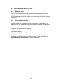
C2-7000 SERIES OPERATION MANUAL
C2-7000 Series
Dual Channel
Video Processor
Operation Manual
Version 2.7
1
C2-7000 SERIES OPERATION MANUAL
C2-7000 Series
Dual Channel
Video Processor
Operation Manual
Version 2.2
C2-7000 SERIES OPERATION MANUAL
Table of Contents
1.0
DISCLAIMER............................................................................................. 1
1.1
Regulatory Agency Acceptance........................................................................... 1
1.2
FCC Statement....................................................................................................2
2.0
IMPORTANT SAFETY INSTRUCTIONS ................................................... 3
3.0
CAPABILITY, TERMS OF REFERENCE AND OVERVIEW SUMMARY 13
3.1
Device Capabilities ............................................................................................ 13
3.2
Terms of Reference ........................................................................................... 14
3.3
Device Overview................................................................................................15
3.4
Models available................................................................................................16
3.5
Input Sources ....................................................................................................17
3.6
Outputs.............................................................................................................. 17
3.7
Windows............................................................................................................ 17
3.8
Layers................................................................................................................18
3.9
Modes................................................................................................................19
3.9.1
Switcher Mode...................................................................................................19
3.9.2
Independent Mode............................................................................................. 20
3.9.3
Dual PIP Mode ..................................................................................................20
4.0
UNPACKING AND INSTALLATION ................................ ........................22
4.1
Shipping Carton.................................................................................................22
4.2
Furnished Accessories ......................................................................................22
5.0
FUNCTIONAL CHECK ................................................................ ............23
5.1
Important Safety Instructions ............................................................................. 23
5.2
Factory Reset ....................................................................................................24
5.3
Initial Operation Check Using Factory Default Settings ......................................24
6.0
CONTROLS AND CONNECTIONS......................................................... 26
6.1
10-button programmable panel.......................................................................... 26
6.2
48-button non-programmable panel...................................................................28
6.3
Inputs and Outputs ............................................................................................ 30
7.0
AUDIO INPUTS AND OUTPUTS.............................................................32
7.1
Connection summary .........................................................................................32
7.2
DARS locking ....................................................................................................32
7.3
Audio outputs in different modes........................................................................33
7.4
Options available ...............................................................................................33
8.0
CHANGING THE OPERATING MODE ................................................... 35
8.1
Operating the Unit as a Video Switcher ............................................................. 35
C2-7000 SERIES OPERATION MANUAL
8.1.1
Switching an Input ............................................................................................. 36
8.2
Operating the Unit as two Independent processors............................................ 36
8.2.1
Selecting Inputs to the Windows ........................................................................36
8.3
Operating the Unit in Picture In Picture Mode (Dual PIP) ...................................37
8.3.1
Selecting Inputs for the Individual Windows.......................................................37
9.0
MENU TOPOGRAPHY AND ADJUSTMENT METHODOLOGY ............. 39
9.1
The High Level Menu Structure ......................................................................... 40
9.2
Advanced menus...............................................................................................41
9.3
Group Names and Descriptions......................................................................... 41
9.4
Items Associated with the Device mode group................................................... 41
9.5
Items Associated with the Adjust outputs group.................................................41
9.6
Items Associated with the Adjust windows group............................................... 45
9.6.1
Extended scaling controls.................................................................................. 48
9.6.2
‘Aspect adjust’ = ‘Advanced’ .............................................................................. 49
9.6.3
‘Aspect adjust’ = ‘Pixel’ ......................................................................................50
9.7
Items Associated with the Adjust keyers group .................................................. 50
9.8
Edge Blend items within the Adjust keyers group .............................................. 52
9.9
Items Associated with the Adjust logos group .................................................... 53
9.10
Items Associated with the Adjust borders group ................................................54
9.11
Items Associated with the Adjust sources group ................................................55
9.11.1 Menu items common to all inputs.......................................................................56
9.11.2 DVI Source Menu Items..................................................................................... 59
9.11.3 RGB Source Menu Items................................................................................... 61
9.11.4 CV & YC Source Menu Items ............................................................................ 62
9.11.5 Still Image Store / Testcard Source Menu Items ................................................62
9.12 Items Associated with the Adjust audio group + other digital audio
adjustments................................................................................................................... 63
9.12.1 Extra item in Adjust outputs ............................................................................... 65
9.12.2 Extra item in Adjust windows ............................................................................. 65
9.12.3 Extra item in Adjust sources .............................................................................. 66
9.12.4 Adjust audio.......................................................................................................66
9.13
Items associated with the Adjust transitions group ............................................. 67
9.14
Items Associated with the Adjust buttons group.................................................68
9.15
Items associated with the Adjust ethernet group ................................................69
9.16
Items associated with the Adjust resolutions group............................................ 70
9.17
Items Associated with the System group ........................................................... 73
10.0
RS232 PORT........................................................................................... 77
C2-7000 SERIES OPERATION MANUAL
10.1
Connection ........................................................................................................77
10.2
Communications protocol .................................................................................. 77
11.0
RS232 / IP CONTROL SPECIFICATION ................................................79
11.1
Communication protocol basics......................................................................... 79
11.2
Packet format ....................................................................................................80
11.3
Function list .......................................................................................................82
11.4
Examples........................................................................................................... 89
11.5
Reading and writing macros .............................................................................. 90
11.5.1 Reading a previously stored Macro....................................................................90
11.5.2 Writing to a macro..............................................................................................91
11.5.3 Run and Restore macros................................................................................... 91
12.0
COMMON OPERATIONS........................................................................93
12.1
Operation of the Keyer.......................................................................................93
12.2
Creating a Macro ...............................................................................................98
12.3
Standards Conversion – NTSC to PAL ..............................................................99
13.0
EDGE-BLENDING SETUP .................................................................... 100
13.1
Introduction......................................................................................................100
13.2
Edge-blending requirements ............................................................................ 101
13.3
Basic setup of the two projectors .....................................................................102
13.4
Connections to the scaler(s) and projectors..................................................... 102
13.5
Initial setup ......................................................................................................103
13.6
Edge-blending activation.................................................................................. 104
13.7
Edge-blending overlap / size............................................................................ 104
13.8
Edge-blending guide lines................................................................................105
13.9
Alignment of projectors.................................................................................... 106
13.10 Gamma correction ........................................................................................... 108
13.11 Brightness compensation.................................................................................108
13.12 Aspect ratio adjustment ................................................................................... 109
13.13 Locking both outputs together.......................................................................... 109
13.14 Other setup approaches .................................................................................. 110
14.0
WINDOWS CONTROL PANEL ............................................................. 112
14.1
Opening screens .............................................................................................112
14.1.1 Selecting a serial port connection ....................................................................112
14.1.2 Selecting an Ethernet connection ....................................................................112
14.2
Connecting to a unit.........................................................................................113
14.3
Application menu’s........................................................................................... 115
14.3.1 File menu......................................................................................................... 115
C2-7000 SERIES OPERATION MANUAL
14.3.2 Communications menu .................................................................................... 115
14.3.3 Tools menu......................................................................................................116
14.3.4 Resolution menu..............................................................................................116
14.4
Scripting tool....................................................................................................116
14.5
Image Loader ..................................................................................................117
14.5.1 Loading Still Images / Testcards......................................................................118
14.5.2 Loading Logos.................................................................................................119
14.5.3 Maximum Image size – how large can my Logo / Still Image / Testcard be?....120
14.6
Resolution Editor .............................................................................................120
15.0
TROUBLESHOOTING AND TECHNICAL SUPPORT........................... 124
15.1
There is no picture on the Output.....................................................................124
15.2
The image is shifted and not fully viewable......................................................124
15.3
The output resolutions no longer appear as expected......................................124
15.4
There is excessive flicker on the Output. .........................................................125
15.5
The Output image is distorted. ......................................................................... 125
15.6
Some colors appear to be incorrect on the CV/YC output ................................125
15.7
How can I reduce color smearing on CV connections?....................................125
15.8
I can no longer adjust the Output image resolution.......................................... 125
15.9
The picture on the video display is black and white.......................................... 125
15.10 The picture on the video display is green.........................................................125
15.11 The RGB input is selected but the image is rolling or pink. ..............................126
15.12 The video signal from my DVD player does not appear to work.......................126
15.13 The output from the 1T-CT-464 is blue. ........................................................... 126
15.14 No video present from the UTP output.............................................................126
16.0
RETURN PROCEDURE ........................................................................127
16.1
Are you sure there's a fault? ............................................................................ 127
16.2
To return a unit for repair .................................................................................127
17.0
WARRANTY POLICY ............................................................................ 129
18.0
CONNECTOR PINOUTS.......................................................................130
18.1
DVI-I connector................................................................................................130
18.2
RS232 / DB9 connector ................................................................................... 130
18.3
4 Pin mini-DIN S-video connector (YC) input ................................................... 130
19.0
SPECIFICATION ................................................................................... 131
19.1
Video Inputs.....................................................................................................131
19.2
Genlock Input ..................................................................................................131
19.3
Independent Output 1......................................................................................131
19.4
Independent Output 2......................................................................................131
C2-7000 SERIES OPERATION MANUAL
19.5
Input/Output Range .........................................................................................131
19.6
Input RGB Sync...............................................................................................132
19.7
Output RGB Sync ............................................................................................132
19.8
SDI/HD-SDI Embedded Audio & Ancillary Data (C2-7200/7210/7260 only) .....132
19.9
SDI/HD-SDI Embedded Audio (C2-7310 only).................................................132
19.10 AES3-id inputs & outputs (C2-7310 only).........................................................132
19.11 Audio Switching (Optional A2-2000) ................................................................132
19.12 Control Methods ..............................................................................................132
19.13 Mechanical ......................................................................................................133
19.14 Environmental..................................................................................................133
20.0
CONTACT INFORMATION ................................ ...................................134
1.0
DISCLAIMER
This product is intended for professional and/or home use. This product is not
intended for use in a medical environment and does not have the required
certifications for such use. Similarly, use aboard any aircraft or spacecraft
while in flight or as an adjunct to any surface, airborne or marine navigation
system or any offshore marine activity, including control of any watercraft, or
any use similar to those specifically herein mentioned is prohibited. Use in the
aforementioned circumstances would require additional testing and
certification.
You have not become the owner of any software - you have merely
purchased the right to use the software. You may make one copy of the
software for your own use. Other copies will be deemed a breach of copyright.
No warranty is made either expressed or implied including but not limited to
any implied warranties of merchantability or fitness for a particular purpose. In
no event shall the supplier or manufacturer of this product be liable for errors
found within, or be liable for any direct, indirect or consequential damages or
loss in connection with the purchase or use of this hardware software or
manual. The sole and exclusive liability to the supplier and manufacturer
regardless of the form of action shall not exceed the replacement cost of the
materials described herein.
By using this equipment you have indicated that you have agreed to the terms
listed above. If you do not wish to agree or the above terms are contrary to
your conditions of purchase you may return the equipment, unused, to your
supplier. All trademarks and copyrights are acknowledged. E&OE.
1.1
Regulatory Agency Acceptance
European ‘CE’ Mark Statement
C2-7100, C2-7110, C2-7200, C2-7210, C2-7260:
Emissions: BS EN 50081-1 (Generic Emission Standard for Residential,
Commercial and Light Industrial)
Immunity: BS EN 50082-1 (Generic Immunity Standard for Residential,
Commercial and Light Industrial)
Safety Directive: BS EN 60065:2002 (Audio/Visual Equipment Safety)
C2-7310:
Emissions: BS EN 55031-1 (Emission: Audio, video, audio-visual and
entertainment lighting control apparatus for professional use)
Immunity: BS EN 55031-2 (Immunity: audio, video, audio-visual and
entertainment lighting control apparatus for professional use)
Safety Directive: BS EN 60065:2002 (Audio/Visual Equipment Safety)
1
1.2
FCC Statement
Class A Device: This equipment has been tested and found to comply with
the limits for a Class A digital device pursuant to Part 15 of the FCC Rules.
These limits are designed to provide a reasonable protection against harmful
interference when the equipment is operated in a commercial environment.
This equipment generates, uses and can radiate radio frequency energy and,
if not installed and used in accordance with the Instruction Manual, may cause
harmful interference to radio communications. Operation of this equipment in
a residential area is likely to cause harmful interference in which case the user
will be required to correct the interference at his own expense.
Caution: This equipment is intended for use in the manner prescribed in the
Instruction Manual. Any user changes or modifications not expressly
approved by TV One Multimedia Solutions could void the user’s authority to
operate the equipment. Connecting this equipment to external devices
requires no specially shielded cabling for FCC compliance. The Instruction
Manual shows or describes the proper connection of this equipment for
operation that insures FCC compliance.
Direct all inquiries regarding FCC compliance to:
TV One Multimedia Solutions
1350 Jamike Drive
Erlanger, KY 41018
859.282.7303
859.282.8225 (Fax)
Manual Version Information
Version: 2.7
Release Date: May, 2009
Manual Copyright Notice
This Operation Manual is the intellectual property of TV One, ©2007-2008. No
portion of this manual may be copied or reproduced in any manner or by any
means, including, but not limited to electronic and electro-mechanical, without
the express written permission of TV One.
2
2.0
IMPORTANT SAFETY INSTRUCTIONS
To insure the best from this product, please read this manual carefully. Keep
it in a safe place for future reference.
To reduce the risk of electric shock, do not remove the cover from the unit.
No user serviceable parts inside. Refer servicing to qualified personnel.
2.1 Power and connections
This unit must be connected to a mains socket outlet with a protective earth
connection.
This unit is not disconnected from the AC power source as long as it is
connected to the wall outlet. The off state for this unit is called standby mode.
In standby mode the unit is designed to consume a reduced quantity of power
compared to normal operating modes.
When not using the unit for a long period of time, insure that the AC power
cord is disconnected from the wall outlet.
The AC wall outlet should be installed near to the unit and be easily
accessible.
Do not plug in or attempt to operate an obviously damaged unit.
2.2 Water and moisture
To reduce the risk of fire and personal injury, operation of this device outdoors
and/or exposure to rain, water or excessive moisture is expressly prohibited.
The apparatus shall not be exposed to dripping or splashing and no objects
filled with liquids, such as vases, shall be placed on the apparatus.
2.3 General care
Do not force switches or external connections.
When moving the unit, disconnect the serial port connections first then the
power cable and finally the interconnecting cables to other devices.
Do not attempt to clean the unit with chemical solvents or aerosol cleaners, as
this may damage the unit. Use a clean dry cloth.
2.4 Location
Installation of this unit should be in a cool dry place, away from sources of
excessive heat, vibration, dust, moisture and cold.
3
2.5 Ventilation
Slots and openings in the sides of the unit are provided for ventilation. To
ensure reliable operation, avoid obstruction of these openings and ensure the
unit is installed in a well-ventilated area.
2.6 Intellectual property
Some IC chips in this product include confidential and/or trade secret
property. Therefore you may not copy, modify, adapt, translate, distribute,
reverse engineer, reverse assemble or decompile the contents thereof.
4
2.0
IMPORTANT: CONSIGNES DE SECURITE
Afin de tirer le meilleur de ce produit, merci de lire attentivement ce manuel.
Gardez-le dans un endroit sûr pour pouvoir le consulter à nouveau.
Afin de réduire le risque de choc électrique, ne retirez pas l’unité de sa
protection.
Aucune pièce réparable par l’utilisateur à l’intérieur. Référez-vous à des
personnes qualifiées.
2.1 Alimentation électrique et connexions
Il faut brancher l'appareil sur une prise du secteur disposant d'une mise à la
terre.
Cette unité n’est pas déconnectée de la source de courant électrique tant
qu’elle est connectée à la prise murale. Le mode éteint de cette unité est
appelé mode de veille. En mode de veille, cette unité est conçue pour
consommer une quantité réduite de courant par rapport aux modes normaux
d’utilisation.
Lorsque vous n’utilisez pas l’unité pendant une longue période, assurez-vous
que le câble d’alimentation électrique est déconnecté de la prise murale.
La prise murale de courant doit être installée près de l’unité et aisément
accessible.
Ne branchez pas et n’essayez pas d’utiliser une unité visiblement
endommagée.
2.2 Eau et humidité
Pour réduire les risques d’incendie et de dommages corporels, l’utilisation de
cet appareil à l’extérieur et/ou son exposition à la pluie, l’eau ou une humidité
excessive est expressément interdite.
L’appareil ne doit pas être exposé aux gouttes ou aux éclaboussures et aucun
objet contenant de l’eau, comme par exemple un vase, ne doit être posé sur
l’appareil.
5
2.3 Entretien général
Ne forcez pas les boutons ou connexions externes.
Lorsque vous déplacez l’unité, déconnectez d’abord les connexions de ports
en série puis le câble d’alimentation et enfin les câbles de connexion avec
d’autres appareils.
N’essayez pas de nettoyer l’unité avec des dissolvants chimiques ou des
produits nettoyants en aérosol, car cela peut endommager l’unité. Utilisez un
chiffon propre et sec.
2.4 Emplacement
L’installation de cette unité doit se faire dans un endroit frais et sec, éloigné
de sources excessives de chaleur, de vibrations, de poussière, d’humidité et
de froid.
2.5 Aération
Les rainures et les ouvertures sur les cotés de l’unité servent à l’aérer. Pour
permettre une utilisation sûre, évitez d’obstruer ces ouvertures et assurezvous que l’unité est installée dans un endroit bien aéré.
2.6 Propriété intellectuelle
Certaines puces IC dans ce produit contiennent des éléments propriétaires
confidentiels et/ou des secrets commerciaux. Vous ne devez donc pas copier,
modifier, adapter, traduire, distribuer, démonter, désassembler, ou
décomposer leur contenu.
6
2.0
INSTRUCCIONES IMPORTANTES DE SEGURIDAD
Para sacar el mejor provecho de este producto, léase este manual con
detenimiento. Guárdelo en un lugar seguro para poder hacerle referencia en
el futuro.
Para reducir el riesgo de calambre, no quite la cubierta del aparato.
No hay piezas utilizables dentro. Remítase todo mantenimiento a personal
cualificado.
2.1 Corriente y conexiones
Esta unidad debe estar conectada a una toma de corriente eléctrica con una
conexión a tierra de protección.
Mientras esté conectada a una toma de electricidad, el aparato seguirá
conectado a la fuente de corriente CA. A la posición de «off» de este aparato
se le denomina posición de espera. En la posición de espera, el aparato está
diseñado a consumir una cantidad reducida de electricidad en comparación
con los modos de operación normales.
Asegúrese de desconectar el cable de corriente CA de la toma de la pared
cuando no va a utilizar el aparato por un periodo largo de tiempo.
La toma CA de la pared ha de estar instalada cerca del aparato y debe ser
fácilmente accesible.
No enchufe ni intente operar un aparato que esté evidentemente dañado.
2.2 Agua y humedad
Para reducir el riesgo de fuego o de daños personales, se prohíbe la
utilización de este aparato en el exterior y/o su exposición a la lluvia, al agua
o a atmósferas de excesiva humedad.
El aparato no debe situarse cerca de zonas en las que haya riesgo de goteo
o salpicaduras. Tampoco deben colocarse objetos que contengan agua
(jarrones, por ejemplo) en el mismo.
7
2.3 Cuidado general
No forzar interruptores o conexiones externas.
Al mover el aparato, desconecte las conexiones del puerto en serie primero,
luego el cable de electricidad y finalmente los cables interconectados a otros
aparatos.
No intente limpiar el aparato con disolventes químicos o productos de
limpieza aerosol, ya que podrían dañar el aparato. Utiliza un paño limpio y
seco.
2.4 Ubicación
Este aparato se debe instalar en un lugar seco y fresco, lejos de fuentes de
calor excesivas, la vibración, el polvo, la humedad y el frío.
2.5 Ventilación
El aparato viene provisto de ranuras y agujeros en los lados para la
ventilación.
Para asegurar una operación eficaz, se debe evitar la obstrucción de estos
agujeros y también asegurar que el aparato se instale en una zona con
adecuada ventilación.
2.6 Propiedad intelectual
Algunos chips con circuito integrado de este producto incluyen propiedad
confidencial y/o propiedad de secreto comercial. Por lo tanto queda prohibido
copiar, modificar, adaptar, traducir, distribuir, usar técnicas retroactivas,
desmontar, o recopilar los contenidos del mismo.
8
2.0
WICHTIGE SICHERHEITSVORSCHRIFTEN
Lesen Sie diese Bedienungsanleitung bitte sorgfältig, um Ihr Produkt optimal
nützen zu können, und bewahren Sie sie zum späteren Nachschlagen an
einem sicheren Ort auf.
Entfernen Sie bitte keinesfalls die Abdeckung, um der Gefahr eines
Stromschlags vorzubeugen.
Im Inneren des Geräts befinden sich keine Teile, die vom Benutzer gewartet
werden können. Lassen Sie Wartungsarbeiten nur von Fachpersonal
durchführen.
2.1 Stromversorgung und anschlüsse
Das Gerät muss an eine geerdete Netzsteckdose angeschlossen werden.
Solange das Gerät mit einer Steckdose verbunden ist, bleibt die
Stromversorgung aufrecht. Der Ausschaltzustand des Geräts wird als
Standbymodus bezeichnet. Im Standbymodus verbraucht das Gerät weniger
Strom als in den üblichen Betriebsarten.
Wird das Gerät über einen längeren Zeitraum hinweg nicht verwendet, ziehen
Sie bitte das Stromkabel aus der Steckdose.
Die Steckdose sollte sich in der Nähe des Geräts befinden und leicht
zugänglich sein.
Verbinden Sie ein offensichtlich beschädigtes Gerät keinesfalls mit einer
Steckdose und versuchen Sie auch nicht, es zu bedienen.
2.2 Wasser und feuchtigkeit
Um die Gefahr eines Brandes oder einer Körperverletzung zu verringern, ist
es ausdrücklich verboten, dieses Gerät im Freien in Betrieb zu nehmen
und/oder es Regen, Wasser oder hoher Feuchtigkeit auszusetzen.
Das Gerät darf keinen Tropfen oder Spritzern ausgesetzt werden und es
dürfen keine mit Flüssigkeiten gefüllte Behälter, wie Vasen, auf das Gerät
gestellt werden.
9
2.3 Allgemeine pflege
Wenden Sie bei der Handhabung von Schaltern und Anschlüssen keine
Gewalt an.
Beim Umstellen des Geräts entfernen Sie zuerst die seriellen Anschlüsse,
dann das Stromkabel und zum Schluss die Verbindungskabel zu anderen
Geräten.
Versuchen Sie keinesfalls, das Gerät mit chemischen Lösungsmitteln oder
Sprayreinigern zu reinigen, da dies das Gerät beschädigen könnte.
Verwenden Sie ein sauberes, trockenes Tuch.
2.3 Aufstellung
Das Gerät sollte an einem kühlen, trockenen Ort aufgestellt werden, fern von
übermäßiger Wärme, Vibrationen, Staub, Feuchtigkeit und Kälte.
2.5 Belüftung
Seitliche Schlitze und Öffnungen sorgen für die Belüftung des Geräts. Um die
ordnungsgemäße Belüftung zu gewährleisten, dürfen diese Öffnungen nicht
verdeckt werden. Sorgen Sie außerdem dafür, dass das Gerät an einem gut
belüfteten Ort aufgestellt wird.
2.6 Gewerbliches eigentum
Einige integrierte Schaltkreise in diesem Produkt enthalten vertrauliche
Informationen und/oder Betriebsgeheimnisse. Sie dürfen daher diese Inhalte
nicht kopieren, modifizieren, adaptieren, übersetzen, verteilen,
rückentwickeln, rückassemblieren oder dekompilieren.
10
2.0
BELANGRIJKE VEILIGHEIDSINSTRUCTIES
Lees deze handleiding zorgvuldig door om het beste uit uw product te halen.
Bewaar het op een veilige plek voor raadpleging in de toekomst.
Haal nooit het omhulsel van de eenheid af, dit om de kans op een elektrische
schok te verminderen. Maak het apparaat nooit open: er bevinden zich geen
door de gebruiker in te stellen onderdelen in het apparaat. Laat service en
onderhoud over aan een gekwalificeerde technicus.
2.1 Elektriciteit en aansluiting
Dit toestel moet worden aangesloten op een netcontactdoos met een
aardsluitingsbeveiliging.
Deze eenheid is niet van de wisselstroom voedingsbron gescheiden wanneer
de stekker nog in het stopcontact zit. Wanneer de eenheid uitstaat, staat deze
nog in de stand-by modus. In de stand-by modus vergt de eenheid minder
stroom dan in de normale "aan" modus.
Wanneer u de eenheid voor langere tijd niet gebruikt, zorg er dan voor dat de
stekker van het wisselstroomsnoer uit het stopcontact is getrokken.
Het wisselstroom stopcontact moet dichtbij de eenheid geïnstalleerd worden
en makkelijk toegankelijk zijn.
Als de eenheid duidelijk beschadigd is moet u deze nooit op het lichtnet
aansluiten of bedienen.
2.2 Water en vocht
Om het risiko op brand en persoonlijk letsel te beperken is het gebruik van dit
apparaat buiten en/of blootstelling aan regen, water of overdadige
hoeveelheden vocht uitdrukkelijk verboden.
Het apparaat mag niet worden blootgesteld aan druppels of bespatting en er
mogen geen objecten die gevuld zijn met vloeistoffen, zoals vazen, op het
apparaat geplaatst worden.
11
2.3 Algemeen onderhoud
Forceer schakelaars of externe aansluitingen nooit.
Bij verplaatsing van de eenheid, de seriële poortaansluitingen eerst
loskoppelen, dan de voedingskabel en als laatste de snoeren naar andere
apparaten.
Probeer de eenheid nooit met chemische oplosmiddelen of
schoonmaakmiddelen in een spuitbus schoon te maken, omdat dit de eenheid
kan beschadigen. Gebruik een schone droge doek.
2.4 Plaatsing
Deze eenheid moet geïnstalleerd worden op een koele droge plaats, uit de
buurt van bronnen van extreme hitte, vibraties, stof, vocht en kou.
2.5 Ventilatie
De sleuven en openingen aan de zijkant van de eenheid zijn voor ventilatie.
Zorg er voor dat de eenheid op een goed geventileerde plek geïnstalleerd
wordt zodat deze betrouwbaar werkt.
2.6 Intellectueel eigendom
Sommige IC chips in dit product bevatten vertrouwelijke informatie en/of
fabrieksgeheimen. U mag daarom de inhoud hiervan niet kopiëren, wijzigen,
aanpassen, vertalen, verspreiden, nabouwen, of decompileren.
12
3.0
3.1
CAPABILITY, TERMS OF REFERENCE AND OVERVIEW SUMMARY
Device Capabilities
The C2-7000 series of Dual Channel Video Processors uses the proprietary
CORIO®2 Engine to control its capabilities. The CORIO®2 series units are
the second generation of the successful CORIO® products. The CORIO®2
features are powerful tools for any application requiring high quality video
signal conversion or image manipulation.
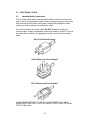
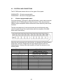
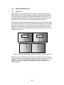
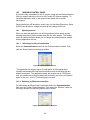
Front and rear of the C2-7110
Each C2-7000 series unit features two independent video processing and
scaling engines (CORIO®2) and two video mixers for maximum flexibility in
handling DVI, RGBHV, RGBS, RGsB, YUV, YPbPr, CV and YC (S-Video)
signals. In addition, the C2-7200 and C2-7300 range also support SDI and
HD-SDI.
The C2-7310 is further extended to process high quality audio data on 16
AES3-id inputs and outputs, as well as on the embedded data within the SDI
and HD-SDI video signals.
Throughout this manual, any feature or function relating present on all C27000 units will be referred to by ‘C2-7000 series’. Any unit-specific functions
or features will be mentioned by specific product name.
At home in both broadcast and display environments the C2-7000 series is
multiple products in one unit. The unit has three basic operating modes to
simplify control.
Switcher Mode - Equally powerful Program and Preview channels allow any
function (next Image, PIP, keying, logo, etc) to be set up and previewed,
totally independent of the Program output. Transition from Preview to
Program is by Cut, Dissolve or Special Effect when the user performs a Take.
Independent Mode - Provides all the power of two completely independent
video processors in one box, each with a full range of features including PIP,
keying, etc. Each output can deliver different formats and resolutions
simultaneously to the other. For example, a presentation being fed to a highresolution display on Output 1 via DVI can be fed to a VCR for recording on
Output 2 via Composite Video.
13
Dual PIP Mode - Any video input can be squeezed and placed into either of
two windows of any size and positioned anywhere on the screen, even
overlapping each other with user defined layer priority control. The windows
can be placed over any other video input as the background. The images in
the windows can then be seamlessly switched or zoomed. Keying can be
applied to each window independently.
General Topography - 4:4:4 RGB sampling provides full bandwidth color,
which allows precise keying, including transparent (soft) Keys. The basic
unit’s 9 video inputs accommodate multiple analog and digital video and
computer signal formats and resolutions. It handles all known HDTV formats
and any RGB resolution up to 2048x2048 - not just some predefined ones, but
virtually ANY resolution. Each of the two independent outputs delivers DVI-I,
RGBHV (or RGBS or RGsB), YUV, YPbPr, Composite and YC (S-Video).
Ultimate flexibility - The C2-7000 series’ output signal format flexibility
assures that the native resolution of virtually any digital display can be
matched. Because of the resolution calculator (included in the Windows®
Control Panel), even new resolutions can be added to the unit. Signal
parameter adjustments can be made for each video input and are stored in
individual non-volatile memories. Dedicated memory is included for multiple
integral Testcards and Logos, so the unit can easily be used as a logo
inserter. The C2-7000 series employs pixel adaptive motion compensation to
de-interlace fast moving images and its automatic 3:2 Pull-down efficiently deinterlaces video from 24 fps NTSC film.
Simple Control - The unit can be controlled from the front panel, via RS-232
or ethernet. The previously mentioned Windows Control Panel (available for
download from our Internet site) affords complete control of the unit and adds
Scripting to facilitate long, complex sequence of commands. Finally, hardware
based, switcher-like CORIO® Console allows a user to control the unit from
hardware, mimicking a classic video switcher device.
3.2
Terms of Reference
In order to operate the C2-7000 series, agreement on terminology is required.
To avoid confusion as you read through this manual, here are the terms of
reference used throughout.
Input Sources: At least nine signal inputs are available (11 on the C27200/7210/7310 and 17 on the C2-7260) and each of these are
buffered and made available to the unit’s video processor. The user
can modify numerous input signal parameters. In addition, the device
can determine the signal format of each input automatically so long as
the signal formats are commonly accepted worldwide standards.
Layers: Imagery is arranged in six layers and made available to the
device’s outputs. The degree of transparency can be set to make
individual layers opaque, semi-transparent or fully transparent. In
addition, with the exception of the 6th layer (background color), the
14
layers can be positioned as desired in the ‘stack’ so that the user can
create any relationship he or she desires.
Modes: There are three modes of operation: Switcher, Independent
and Dual Picture in Picture (Dual PIP). In Switcher mode, inputs and
manipulations are shown on one output immediately and transferred to
the second output when a ‘Take’ button is pressed. In the Independent
mode, input selections and manipulations are made to appear on the
two outputs independently yielding two separate signal paths. In the
Dual PIP mode, the functionality of both processors is combined to
provide two Picture in Picture windows. The outputs are comprised of
the same signals but different key and fade values can be set for each
of the unit’s outputs.
Processor: Refers to the CORIO®2 processing engine within the unit
of which there are two. Each is able to scale, shrink, zoom and adjust
the selected input source.
Outputs: There are two output channels provided, each channel
comprising of a DVI-D, RGBHV, Composite, and YC output. The
function of each output channel depends on the mode of operation
selected. The user can select the output signal format as desired and
can set the signal resolution (except for PAL/NTSC signals).
Windows: Windows are containers for the input signals. They can be
sized and positioned as required within the output window.
3.3
Device Overview
The C2-7000 series provides a means for the user to select sources from the
inputs and present them to the two outputs in various ways. The imagery on
the outputs is comprised of the video layers of live (moving) video plus static
video sources such as internally stored logos and testcards.
The outputs are then further defined by the operational mode selected:
Switcher, Independent and Dual PIP (Picture in Picture).
15
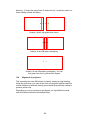
3.4
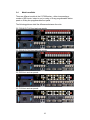
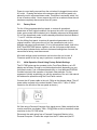
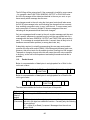
Models available
There are different models in the C2-7000 series – either incorporating a
number of SDI inputs / output or not, or using a 10-way programmable button
panel or 48-key non-programmable front panel.
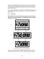
The following pictures detail the differences between the units:
C2-7100 & C2-7110 front and rear panels:
C2-7200 & C2-7210 front and rear panels:
C2-7260 front and rear panels:
C2-7310 front and rear panels:
16
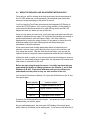
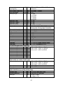
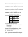
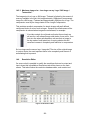
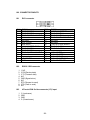
In summary, the following table details the main differences:
Model
Inputs
Outputs
C2-7100 3xDVI-I 3xCV 3xYC
2xDVI-I 2xCV 2xYC
C2-7110 3xDVI-I 3xCV 3xYC
2xDVI-I 2xCV 2xYC
C2-7200 3xDVI-I 3xCV 3xYC 2xSDI 2xDVI-I 2xCV 2xYC 2xSDI
C2-7210 3xDVI-I 3xCV 3xYC 2xSDI 2xDVI-I 2xCV 2xYC 2xSDI
C2-7260 3xDVI-I 3xCV 3xYC 8xSDI 2xDVI-I 2xCV 2xYC 2xSDI
C2-7310 3xDVI-I 3xCV 3xYC 2xSDI 2xDVI-I 2xCV 2xYC 2xSDI
+ 16xAES3-id
+ 16xAES3-id
10-key panels are programmable; 48-key panels are not.
3.5
Keys
10
48
10
48
48
48
Input Sources
The C2-7000 series accepts a very wide range of input types. Adaptors are
provided to allow configuration of the device to accept and process virtually
any image source. The device will automatically identify the signal type or
image resolution for virtually any input and manual intervention is possible for
many non-standard inputs.
Valid processor inputs also include sources not associated with the input
connectors. Firstly there are multiple test cards which are stored within the
device’s non-volatile memory for later recall. Secondly it is even possible to
internally cascade one output using it as the Input Source for the second
processor.
3.6
Outputs
Two Outputs are provided on the C2-7000 series. The user can select the
type of output signal desired for each Output and each Output can be
adjusted independently of the other. The exact function of the Output depends
on the mode as explained previously.
3.7
Windows
Windows can be thought of as containers for imagery. Input selections from
the various connectors as well as integration of internal sources such as
Logos are all part of the Windowing capabilities of the C2-7000 series.
There are two scalable windows available for use, ‘A’ and ‘B’––one for each
processor in the C2-7000 series–– and each is part of the layering hierarchy
used in the C2-7000 series. Images can be zoomed, shrunk, keyed,
positioned and scaled within the Window or as a part of the Window. There is
also a Lock Source Window ‘Z’, plus Logo ‘a’ and Logo ‘b’ none of which are
re-sizeable.
The Window itself can be thought of as a hole cut into the overall output
image. The edges of the cut out can be hard or soft and the nature of the
Window itself can be opaque, semi-transparent or invisible depending on how
the various Layers, Fade levels and Keyers are set up.
17
Within the nomenclature that follows, the Windows will be associated with one
or both of the two Outputs as explained in the section detailing Modes of
Operation.
Windows are an integral part of the C2-7000 series and play a central part in
understanding how to operate the device.
3.8
Layers
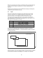
There are six image layers comprising of two static logo sources (stored
internally in the device), two scalable windows that contain video, a lock
source and, finally, a color background which is always the 6th layer.
The image layers are given designators for the purposes of identification
when operating the C2-7000 series. The designators are case sensitive. The
letters and their meanings are as follows:
Window
a
b
A
B
Z
Description
Logo “a” (Static - not scaled)
Logo “b” (Static – not scaled)
Window “A” (Live – scalable)
Window “B” (Live – scalable)
Window Z Lock Source (Live – not scaled)
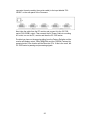
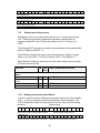
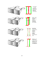
Since the color background layer is always layer number six, it can’t be
moved and is given no designator. In the factory default condition, the layers
are arrayed as shown:
Color Background
Z (Lock Source)
a
b
A
B
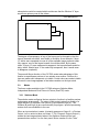
With the exception of the color background layer, the layers can be re-ordered
so that different orientations are displayed. For example, the combination
18
shown below could be created which would mean that the Window “A” layer
would have primacy over all the others:
Color Background
Z (Lock Source)
A
a
b
B
The degree of transparency of any of the layers can be changed so that the
layer(s) beneath are visible, semi-visible or invisible. As an example, if layer
“A” above were expanded to cover all of the available image area and made
fully opaque, none of the layers beneath it would be visible. By the same
token, if Layer “A” were made semi-transparent, the layers beneath would be
dimly visible. Should layer “A” be made fully transparent, then it would seem
to disappear completely.
The powerful Keyer function of the C2-7000 series takes advantage of this
feature to superimpose portions of one window over another. Portions of a
layer are made semi-transparent or invisible. Certain colors are made invisible
the result is one image appears to float above another on the layer stack.
3.9
Modes
The three modes available in the C2-7000 series are Switcher Mode,
Independent Mode and Dual Picture in Picture (Dual PIP) mode.
3.9.1 Switcher Mode
The switcher mode configures the two outputs to function in a familiar preview
and program arrangement. The output in this mode is actually a display of a
single Window (A), optional Lock Source (Z) and optional Logo (a). The
Window (B) and Logo (b) are used internally for program / preview processing
and as such are unavailable to the user.
When an input selection is made, it instantly appears on Output 2––a Preview
Output––but no action is taken on Output 1. The “Program” Output (Output 1)
retains the last image selected when in the Switcher mode until the user
presses button number 2 on the front panel. Button number 2 is the ‘Take”
19
button when in the Switcher mode and pressing it causes the image present
on Output 2 to also appear on Output 1. Special control logic within the C27000 series allows the movement of the image from Output 2 to Output 1 to
be either instantaneous or the new Output 1 image can gradually replace the
previous image on Output 1 via a cross fade or a wipe. The time available for
the cross-fade or wipe can be up to 5 seconds, controlled in .1-second
increments.
3.9.2 Independent Mode
In the Independent mode, the dual processor circuitry is divided into two
separate but equal signal processors. Window “A” and Logo “a” is dedicated
to Output 1 and Window “B” and Logo “b” is dedicated to Output 2. Each of
the Outputs can have a separate Lock Source (Layer Component Z), separate
Color Background and separate Input Sources.
Graphically, the two Outputs layers will appear as shown:
Color Background – Output 1
Color Background – Output 2
1Z Lock Source
2Z Lock Source
Logo “2b”
Window “1A”
Window “2B”
Logo “1a”
From the drawings above, it can be seen that a limited layering scheme is in
place while in the independent mode. You can utilize the transparency feature
and the Keyer capability on each Output to make any portion of the window
visible.
You can use the input buttons to select the images held within the windows
and the selection process would be for only one output without having an
effect on the other.
Similarly, you can make the Color Background layer different colors or cover it
with a Lock Source or Window.
Finally, the logo generator can be employed to superimpose a logo over each
Output independently.
3.9.3 Dual PIP Mode
In the dual Picture In Picture mode, the same Lock Source (Layer Component
Z) is applied to both Outputs 1 and 2. The Imagery present on those Outputs
20
therefore will be locked to the single Lock Source even though there are two
Outputs available.
From a practical standpoint, this means that there is only one lock source
available and both outputs will contain the same lock source imagery.
The Keyers can adjust the components of each Window independently so as
to make a portion of the underlying Window pierce the overlaying Window and
the logos can be used as desired in the Output imagery.
Two Windows are available, “A” and “B”, on each of the two Outputs. Each
Output displays the Windows at the same position and sizing. By changing
the order of the layers either PIP can be placed in front of the other and the
balance of the layers can be utilized as well.
Color Background – Output 1
1Z Lock Source
Logo “1a”
Color Background – Output 2
Window “1A”
Window “2A”
2Z Lock Source
Logo “2a”
Window “1B”
Window “2B”
Logo “1b”
Logo “2b”
Inputs switched into Windows “A”, “B” and “Z” appear on both outputs (in
other words, the imagery present in Window 1A is the same as 2A and the
imagery present in Window 1B is the same as that present in Window 2B).
Positions and sizing is also the same for both Outputs however you can utilize
independent Keying, fading and layering on each output.
21
4.0
4.1
UNPACKING AND INSTALLATION
Shipping Carton
The C2-7000 series arrives double boxed for maximum protection during
shipping. You are encouraged to retain both boxes and all packing material so
the unit can be returned in the unlikely event that repairs should ever become
necessary.
4.2
Furnished Accessories
Carefully unpack the carton and perform an inventory of the contents. In
addition to the C2-7000 series Dual Channel Video Processor, the standard
accessories include:
2 RGBHV I/O Adaptors, DVI-A to HD15
1 AC Power Cable
1 Operations Manual
1 Rack-mount Kit, 2 Ears and 8 Screws
If any items are missing or defective, contact your supplier. If you are unable
to resolve the problem with your supplier, contact TV One via the web at
http://www.tvone.com/support for prompt replacement.
22
5.0
5.1
FUNCTIONAL CHECK
Important Safety Instructions
The AC power cable (Mains Lead) furnished with the unit will conform to the
type in use at your geographic locale. Please compare the plug on your cable
with the three types of power cable plugs currently being shipped to make
certain you have received the correct power cable.
If you did not receive the correct cable, DO NOT attempt to modify the
incorrect cable. Instead, immediately contact your dealer or contact TV One at
the sales office nearest to your geographic location and request the proper
cable.
US AC Cable Plug Example:
UK AC Mains Lead Plug Example:
EU AC Mains Lead Plug Example:
AGAIN, DO NOT ATTEMPT TO MODIFY AN INCORRECT AC CABLE
(MAINS LEAD). REPLACE IT WITH A CORRECT PART PRIOR TO USING
THE C2-7000 series.
23
Power is never totally removed from the unit when it’s plugged into an active
AC outlet. Pressing the button at the extreme right on the front panel only
places the unit in a powered down mode. This button is a standby switch, not
a true off and on switch. Never remove the unit from a cabinet unless the unit
has been completely disconnected from AC power.
5.2
Factory Reset
For the 10-key programmable front panel: to restore all operational
parameters to their original condition, first ensure the unit’s in the operational
mode, green power led illuminated (not in Standby red power led illuminated).
If it is in the operational mode, hold the standby switch and then hold Buttons
“1” and “2” until the unit beeps.
For the 48-key front panel: to restore all operational parameters to their
original condition, first ensure the unit’s in the operational mode (not in
Standby red power led illuminated). If it is in the operational mode, hold in the
SHIFT and RESTORE buttons together until the unit beeps multiple times –
the first beep indicates that a restore to last-saved settings has occurred, the
second that a factory reset has occured.
All stored settings except resolutions are lost when the unit is reset. A
Firmware update is the only way to perform a complete factory reset
5.3
Initial Operation Check Using Factory Default Settings
The C2-7000 series can be operated via the Front Panel Buttons, an LCD
display and a Rotary Encoder or multi-directional switch (depending on your
front panel version), via a Windows based utility or via a dedicated CORIO®
Console hat mimics the operation of a classic video switcher. For the
purposes of initially acquainting you with the operation of the unit, this manual
will address the operation using the Front Panel controls.
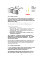
Connect the AC power cable to the unit. (Refer to the diagram below. The AC
power cable connects to the socket labeled “Power 100v – 240v 47-63Hz”
located on the left side of the rear panel as shown.)
We’ll be using a Personal Computer for a signal source. Make certain that the
monitor resolution can display 1024 x 768 @ 60Hz as this is the default output
resolution for the C2-7000 series.
Disconnect the cable going from a Personal Computer’s Monitor to the
Personal Computer. Connect the output from the PC video card (the PC
24
connector formerly used by the monitor cable) to the input labeled “DVII/RGB1” on the rear panel of the Processor.
Next, take the cable from the PC monitor and connect it to the C2-7000
series’ DVI-I/RGB1 output. Then connect the AC Power Cable to a working
AC outlet, turn on the PC, monitor and then the C2-7000 series.
Provided you have not changed anything from the Factory Defaults and the
monitor will display output 1024x768@60Hz and the CORIO® Testcard, by
pressing button 3 the monitor will the show the PC’s. If this is the result, the
C2-7000 series is passing and processing signals.
25
6.0
CONTROLS AND CONNECTIONS
The C2-7000 series comes with one of two types of front panel:
CORIO® STD – 10 button programmable.
CORIO® EXP – 48 button non-programmable.
6.1
10-button programmable panel
Front panel buttons 1 through 10, plus the Shift button, govern what inputs are
applied to the C2-7000 series’ two Video Processors. They also store user
created, signal manipulation Macros and access some frequently used control
functions.
The user can assign any of the input sources and some frequently used
control functions to any of the input buttons (with the exception of the Shift
button and Power Button).
When the unit is powered up for the first time, (or whenever a Factory Reset is
performed), the button assignments and input signal types are set to an
initialized state. A listing of the initial condition is shown for reference in the
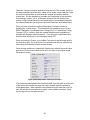
following table:
Button Number
1
2
3, 4, 5, 6, 7, 8, 9, 10
Shift + 1
Shift + 2
Shift + 3
Shift + 4
Shift + 5
Shift + 6
Shift + 7
Shift + 8
Shift + 9
Shift + 10
Button Function
Toggles Windows A, B & Z
‘Take’ button in Switcher Mode
Selects an input – see below
Toggles between Channel 1 & 2
Highlights Active Window
Freeze
Key on/off
Macro1
Zoom Zoom +
Shrink Shrink +
Restore
26
Button
Number
3
4
5
6
7
8
9
10
C2-7100
default
RGB1
RGB2
RGB3
CV1
CV2
YC1
YC2
TC1
C2-7200
default
RGB1
RGB2
CV1
CV2
YC1
SDI1
SDI2
TC1
All buttons except the Shift button and Power Button can be reassigned;
however, buttons “1” and “2” should not be changed since such a change will
make operation of the unit via the Rotary Encoder Control more difficult.
The unit is controlled from the front panel by using the rotary knob and the
LCD screen. The Rotary encoder knob has two functions, rotate to navigate
through the menu structure and push to enter a sub menu or change a
parameter.
Parameters that can be altered are indicated on the LCD screen by “[ ]”
brackets, simply press the rotary knob and these brackets will flash indicating
the parameter can be adjusted, then rotate the knob to adjust and when the
require setting is shown press the rotary knob again to end the adjustment.
The settings for the unit can be saved at anytime by pressing and holding the
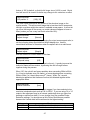
rotary knob until the screen shows the screen:
Info :
Settings stored
In order to facilitate ease of use, the first two characters of every menu
indicate the current Output and Window that is being adjusted; i.e. 1A =
Output 1, Window A. In order to quickly change between the Window and
Output under adjustment, the first programmable button (1) is programmed to
cycle through the windows: A->B->Z>A … and this same key (when the shift
key is also pressed) cycles through the Outputs 1->2->1… If you ever get lost
as to which window is 1A, etc., simply pressing shift and button (2) will
highlight the window on its associated output by placing a border around it.
27
6.2
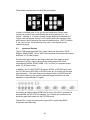
48-button non-programmable panel
All 48-key front panels have the same button arrangement on the left and right
sides of the front panel, with the main input selection buttons differing
between units as shown below:
C2-7110:
C2-7210 & C2-7310:
C2-7260:
28
With these front panels, you can directly select the inputs to route to the two
outputs of the C2-7000 series unit. Depending on the Mode you’re in
(Switcher, Independent and Dual PIP), the input selection button will have
different effects:
Mode
Switcher
PROGRAM 1/A button
Selects that input on Output 2.
Performs a seamless switch
on Output 1.
Independent Selects that input on Output 1
Dual PIP
Selects that input in Window A
– on above Output 1 & 2,
depending on PIP sizes.
PREVIEW 2/B button
Selects that input on Output 2
– has no effect on Output 1
Selects that input on Output 2
Selects that input in Window B
– on above Output 1 & 2,
depending on PIP sizes.
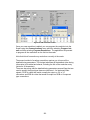
The unit is controlled from the front panel by using the multi-directional switch
and the LCD screen. The switch has two functions, click left and right to
navigate through the menu structure and push to enter a sub menu or change
a parameter:
Parameters that can be altered are indicated on the LCD screen by “[ ]”
brackets, simply press the switch and these brackets will flash indicating the
parameter can be adjusted, then click the switch left and right (and in some
cases up and down) to adjust. When the required setting is shown press the
switch again to end the adjustment.
Info :
Settings stored
The settings for the unit can be saved at anytime by pressing and holding the
multi-directional switch until the screen shows the screen:
29
These buttons are the same on all 48-key front panels:
In order to facilitate ease of use, the first two characters of every menu
indicate the current Output and Window that is being adjusted; i.e. 1A =
Output 1, Window A. In order to quickly change between the Window and
Output under adjustment, buttons 1 & 2 instantly select the required output,
with buttons A and B selecting the required scaled window. SHIFT-A selects
Z, the Lock source. Not all selections are valid – this depends on the
operational mode.
6.3
Inputs and Outputs
The C2-7000 series has three DVI-I inputs (which can be used for DVI-D,
RGBHV, RGsB, RGBS, YUV or YPbPr sources) three Composite video inputs
and three YC (S-Video) inputs.
Provision has been made for two Output channels. Each output channel
comprises of a DVI-I output (which can be used to output DVI-D and
simultaneous RGBHV, RGsB, RGBS, YUV, or YPbPr) a Composite output
and a YC (S-Video) output.
In addition, the C2-7200/7210/7310 has two SD-SDI or HD-SDI inputs, with
the C2-7260 having 8 SD-SDI or HD-SDI inputs (any 2 of which can be used
simultaneously) – with each Output also being mirrored on SD-SDI and HDSDI output connectors (for when the selected output resolution is a valid
standard- or high-definition TV signal).
Connecting an Analog Signal (RGB/YCbCr) to any of the DVI-I connectors is
accomplished via DVI to HD-15 Adapters, five of which are furnished in the
accessory pack that comes with the C2-7000 series.
The two DVI-I output connectors also support DVI-I and Analog RGB /
Component simultaneously.
30
System
Advanced menus
[Off]
The above menu item must be ‘On’ to activate certain menu items. These
typically control the more advanced items in the menus.
31
7.0
AUDIO INPUTS AND OUTPUTS
C2-7000 series units with AES3 digital audio have extra connections at the
rear to bring the audio in and feed the mixed & routed channels back out
again.
7.1
Connection summary
The connectors on the rear provide the following connections:
Connector: AES3-id I/O 1
AES3-id I/O 2
Inputs:
AES1 to AES8, DARS1 AES9 to AES16, DARS2
Outputs:
CH1 to CH8 for output 1 CH1 to CH8 for output 2
Note that all 16 AES3-id inputs (AES1 to AES16) are freely available for use
within the unit for routing and mixing, but that the outputs are designed to
match the video outputs. Therefore, since the unit has 2 outputs, the audio
outputs have 2 connectors (as shown above) – in which the AES3-id audio
signals are referred to as ‘CH1 to CH8’.
Note that where an SDI output is present, these digital audio outputs are also
embedded into this signal. The AES3 audio outputs and the embedded SDI
audio channels always follow each other. This is also why there are 8 stereo
channels on each output connector – since SDI has this many audio signals
that can be embedded within it.
Please also note that the unit processes 8 stereo audio signals for each video
input and output. Therefore you will find that each video signal (e.g. CV1) can
have 8 audio signals assigned to it. If you’re outputting SDI, then all 8 routed
signals will be embedded and all 8 sources for the video being routed may
therefore need to be setup – otherwise you may just want to define 1 audio
source and only use 1 AES3-id output.
7.2
DARS locking
A DARS AES3-id input is available on both I/O connectors – this is to allow
locking to a studio reference source. This is enabled using the ‘Lock’ menu
item in ‘Adjust outputs’, by setting it to ‘DARSlock’.
The DARS input must be a 48kHz AES3-id signal, as the 48kHz AES3-id
audio outputs will be synchronized to this source. The unit’s internal pixel
clock generator will also be synchronized to this source, so it is vital that the
DARS input is a stable signal.
Note that in Independent mode, DARS1 and DARS2 are completely
independent of each other – the first synchronizes the outputs on AES3-id I/O
1 and the second synchronizes the outputs on AES3-id I/O 2.
32
7.3
Audio outputs in different modes
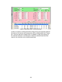
The following table defines the usage of the outputs in each of the unit’s
modes:
Mode
AES3-id I/O 1
AES3-id I/O 2
(and SDI1 output)
(and SDI2 output)
Switcher
‘Program’ audio output –
‘Preview’ audio output – audio
audio follows the video during follows the Preview video
a transition*
source*
Independent Audio follows the video
Audio follows the video source
source for 1A*
for 2B*
Dual PIP
Audio follows the video
Audio follows the video source
source for 1A*
for 1B*
*Unless audio-follow-video (AFV) is overridden in the Adjust outputs menu,
where it can be forced to being a fixed audio source.
Also note that since there are 8 stereo audio channels per video source, the
above describes what happens for all 8 audio outputs – e.g. in Switcher mode
during a Take, all 8 stereo audio outputs will fade from one source to another
simultaneously.
7.4
Options available
Since the HD44 connector where these audio inputs and outputs are present
is not very ‘user friendly’ (but had to be used for space reasons), various
optional accessories are available for situations where the de-embedding and
re-embedding of the SDI audio channels is not sufficient.
Option
product
code
A2-7393
Details
Break-out of 8xIN & 8xOUT to AES3-id signals on BNC connectors via
a 1.5m lead
A2-7302
Break-out and conversion of 8xIN & 8xOUT to AES signals on XLR
connectors
A2-7312
Break-out of 8xIN & 8xOUT to AES3-id signals on BNC connectors on
rack-mountable plate, complete with 1.5m lead (as per A2-7393)
A2-7322
Break-out and conversion of 8xIN & 8xOUT to analog audio on
33
terminal blocks
A3-7342
Break-out and conversion of 4xIN & 4xOUT to analog audio on XLR
connectors
Note: in all cases, a DARS input is also available on a BNC connector.
Since there are 2 AES3-id I/O connectors on the rear of the C2-7310 unit, you
can mix and match up to 2 of the above A2-7300 series units.
34
8.0
CHANGING THE OPERATING MODE
As previously explained, the C2-7000 series has two independent video
processors and three operating modes: Switcher Mode, Independent Mode
and Dual Picture in Picture (Dual PIP) Mode.
Within these three modes there are over 20 additional functions that can be
accessed either within a single channel or layered across both channels.
These individual functions will be explained later in the manual but for now, it
would be well to learn the basics of the three modes. The discussions that
follow are all referenced to the C2-7000 series’ default condition upon initial
application of power or after a Factory Reset has been performed.
8.1
Operating the Unit as a Video Switcher
When the C2-7000 series is initially turned on the first time (and after any
Factory Reset), it will be in the Switcher mode. If a mode change is made to
either Independent mode or Dual pip mode, and the power is not totally
removed from the unit by unplugging it from the AC supply, the last selected
mode will be retained even if the unit is switched off using the power switch.
In the following discussion, the assumption is made that the unit is being
turned on for the first time and is therefore in the Factory Default condition.
Connect the DVI-I #1 Output to either a DVI-I compliant monitor or to a RGB
Analog Component monitor using appropriate adapters if necessary. Connect
a second monitor to the DVI-I #2 Output. These will become your Program
and Preview monitors respectively.
By changing the Output Resolution to NTSC/PAL and type to CV/YC, you can
also connect monitors to the Composite Video or YC Video Outputs (instead
of RGB), however the quality of the signal will not be as good as the signal
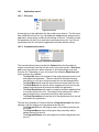
present at the respective DVI-I / RGB outputs.)
CORIO2 C2-7100
TV One
The LCD screen will display the model number when you initially apply power
to the unit or perform a reset, you should make note of this number in case
you require technical assistance.
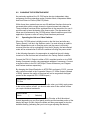
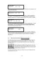
Device Mode
Mode
[
Switcher]
If not in the Switcher mode, press the Rotary Encoder or Multi-directional
Switch (depending on your front panel version) and the brackets portion of the
display will begin to flash. Adjust the Mode and then press again to stop the
brackets flashing (indicating that you’re no longer adjusting that feature).
35
When in switcher mode Output 1 will be the program feed and Output 2 will be
the preview feed. Most users will position the monitor connected to Output 2
on the left and the monitor connected to Output 1 on the right. Since most
people naturally work from left to right, it would be logical to display the image
you are previewing (the image on the monitor connected to output 2) on the
left.
8.1.1 Switching an Input
Using the appropriate input button or the Adjust Windows, select the Input
Source you wish to place on the program monitor. If the input is assigned to a
button then the LED above the respective button will begin to flash and the
image will appear on the Preview Monitor.
It’s now time to ‘Take’ the Input Source, placing it on the Program output.
Pressing the ‘Take’ button allows you to replace the Input Source currently in
place on the Program monitor with the Input Source on the Preview monitor.
8.2
Operating the Unit as two Independent processors
The second mode of operation is the Independent Mode. In this mode, each
of the unit’s processor engines are controlled separately and two independent
Outputs are possible.
To help explain how to enter this mode, the frame of reference will be the
Factory Default condition. At this time, perform the Factory Reset as
explained in section 5.2 above.
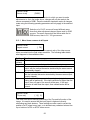
After the system resets, the initial screen will be as follows:
CORIO2 C2-7100
TV One
Move to the next menu item and change it until it appears as follows:
Device Mode
Mode
[
Switcher]
Note: There is no Preview available in the Independent mode. Changes made
to the inputs for either Output occur immediately using the currently defined
transition..
8.2.1 Selecting Inputs to the Windows
As we previously discussed, in this mode Window A and Logo a are dedicated
to Output 1 and Window B and Logo b are dedicated to output 2. Selections of
the Inputs to each Window and their respective Output are made in conjunction
with the Shift Button and Button Number 1 (press and hold the Shift button and
36
then press button number 1 to toggle between Output 1 and 2.), or via the
dedicated input selection buttons on a 48-key panel.
The function of the A B & Z buttons in this mode allows you to change
between the active window for the Output and Window Z only. E.g. With
Output 1 selected you can select Windows A and Z; with Output 2 selected
you can select Windows B and Z.
Select the desired input by pressing the appropriate button. When the button
is pressed, the image will immediately appear on the output. Select Output 2
(Shift & button number 1 on the 10-key front panel) to change to the other
output. Repeat the activity to make your selection for the second video path
and note the LCD display is changing from 1A to 2B during the process.
As a part of this familiarization exercise, you may wish to resize the images by
using either using button number 9 and the shift key on the 10-key panel, or
the dedicated PIP & SIZE buttons on the 48-key panel.
8.3
Operating the Unit in Picture In Picture Mode (Dual PIP)
The Picture In Picture mode is a very powerful function available on the C27000 series because unlike many products on the market, you have two P-I-P
functions available and each is independent of the other with respect to signal
type and content.
As before, the frame of reference will be the Factory Default condition. At this
time, perform the Factory Reset as explained in section 5.2 above.
After the system resets, the initial screen will once again be as follows:
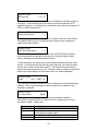
CORIO2 C2-7100
TV One
Change the Mode to Dual PIP as shown below:
Device mode
Mode
[
Dual PIP]
8.3.1 Selecting Inputs for the Individual Windows
10-key front panel: button 1 toggles between the Window “Z” (The Lock
Source), Window “A” and Window “B”.
48-key front panel: use the dedicated input selection buttons.
Since there is no Lock Source automatically selected in the Factory Default
and Lock mode is set to off, nothing will happen on the screens when you
have the Z Input Source selected.
37
Select Window A for adjustment so that the top line of the LCD display shows
1A. When you have Window A available for change, press the input button for
the signal source you desire to place in Window A.
This selected window can now be adjusted with the SIZE (48 key panel) or
Shrink -/+ buttons (10 key panel). The ZOOM button will zoom the image
within the confines of the Window area whereas the Shrink button will change
the size of the window itself and thereby increase or decrease the coverage
area of the image with respect to the monitor screen.
In the default condition, Window “A” will always appear full screen in front of
Window “B”. Changing Window A’s size, or simply pressing PIP on the 48 key
panel, will then let you see Window B behind Window A. Later we’ll be
exploring the menu structure used in the C2-7000 series. It’s within the
various yet-to-be explained menus elements that we’ll gain access to all the
powerful operational and technical capabilities.
38
9.0
MENU TOPOGRAPHY AND ADJUSTMENT METHODOLOGY
From here on, we’ll be looking at the high-level menu structure employed in
the C2-7000 series and, more importantly, the individual menu items that
allow you to take advantage of the power of the unit.
You’ll be using the Front Panel controls and the Integrated LCD Display to
control the C2-7000 series. You’ll turn the rotary encoder (10 key panel) or
move the multi-directional switch left or right (48 key panel) and the LCD
display will show you where you are in the menu.
Once you are where you want to be, you’ll press the knob/switch and this will
enable an adjustment to be made. You’ll note that the brackets surrounding a
particular parameter’s value will begin to flash. You’ll then make the
adjustments by turning the rotary encoder (10 key panel) or move the multidirectional switch left or right (48 key panel) and then pressing the
knob/switch to finish the process.
A few menu items have multiple parameters within an individual menu
selection. In those cases, you’ll adjust the first, move to the next item, and
then adjust the second. With the multi-directional switch, you can use the
up/down direction to adjust the second parameter whilst the first is flashing.
Holding the knob or switch in for a few seconds stores all changes in memory.
Unless you intentionally change it again later, the adjustment will remain even
after power is removed from the unit.
Before we start going through the menus, it’s vitally important that you
understand the method of changing between the Outputs (1 and 2) and
Windows (A B & Z). Experiment with them until you’re confident you
understand how they work as they are vital controls of the unit.
Let’s review the functions of buttons 1 & 2 plus the Shift button on the 10-key
front panel again:
Button Number
Button Function
1
Toggles Windows A, B & Z
Shift +1
Toggles between Channel 1 & 2
2
‘Take” button in Switcher Mode
Shift + 2
Highlights Active Window
Control on the 48-key panel is even simpler – just press the Output number or
Window letter you need to adjust.
As you make adjustments, the front panel LCD display will normally show
which Channel or Window you’re working with. If you become lost with the 10
39
key panel, you can use the Shift Key and button 2 to highlight the Window you
are working with on the Video monitor.
The LCD display will show what Parameter, Output plus the Window you are
working with. (2A for instance means you are working with Output 2, Window
A – and therefore you’re in Independent mode). Before you make a change,
note the indication on the LCD display and make certain you are about to
make an adjustment in the area you actually want to change or adjust. Before
you actually try to make any adjustments, it is strongly recommended that you
become familiar with the control methodology using the Buttons and LCD
display.
With these explanations and cautions in mind, let’s look at the C2-7000 series
menu.
9.1
The High Level Menu Structure
Menus controlling the C2-7000 series are arranged so that a particular
general function has a group name and then, beneath that group name, a
collection of related individual functions are arrayed.
In some cases the functionality is global––meaning it has an effect on the unit
as a whole. In the majority of cases, the function is related to a specific
operational area of the unit and these areas frequently have the Output and/or
Window label indicated on the front panel LCD display.
There are two screens that appear before the Group Menus are accessed.
The first is the Banner display indicating the model of the unit:
CORIO2 C2-7100
TV One
Rotating the Rotary encoder clockwise (or clicking the multi-directional switch
to the right) moves to the following screen:
www.tvone.com
SW: 15. PT: 12, BT: 13
The SW number refers to the version of firmware loaded into C2-7000 series,
this software can by upgraded from the support website,
http://www.tvone.com/support. The PT and BT numbers refer to Hardware
version information and are of interest to the Technical Support Group should
you ever need assistance.
It is unfortunately not possible for hardware to be upgraded.
Change from the banner screen and note the name and description of the
various Group Menu Names.
40
9.2
Advanced menus
Note that the ‘Advanced menus’ menu item must be ‘On’ to activate certain
menu items.
9.3
Group Names and Descriptions
Menu Group Name
Group Description
Device mode
Allows selection of switcher, independent and pip mode
Adjust outputs
Controls output parameters
Adjust windows
Controls characteristics of the pip windows
Adjust keyers
Controls the luminance keyer and chroma keyer
Adjust sources
Controls signal input parameters
Adjust logos
Controls characteristics of logo files and outputs
Adjust borders
Controls the window border functions
Adjust transitions
Controls input transitions
Adjust buttons
Controls button assignments and preview/program action
Adjust ethernet
Controls IP addresses and network parameters
Adjust resolutions*
Controls unit’s input / output resolution table
System
Controls global system parameters
*This menu item is hidden until enabled by setting ‘Advanced menus On’ in
the System menu.
9.4
Items Associated with the Device mode group
Device mode
Mode
[
Switcher]
Accessing this group allows you to select one of three high-level operating
modes: Switcher, Independent or Picture-In-Picture. For a discussion of each
of these modes, see section 3.9 Modes
9.5
Items Associated with the Adjust outputs group
This menu group allows adjustments to be made that specifically affect the
output of the unit, including output resolution and locking/overlaying onto a
computer or video source.
800 x 600 60Hz
Lock mode
[Off] [RGB1]
This menu item allows the lock mode to be selected and the lock source to be
defined. The top line of the display shows the current detected resolution of
the selected lock source (RGB1 in this example). The lock mode can be either
Off, Genlock or Lock & Mix, with the operation of these shown in the following
table:
Lock mode
Description
41
Off
Genlock
Lock & Mix
Frm.lock*
The output resolution of the Output is defined by the setting
for Output Resolution and there will be no background
source visible.
The output video will be “Genlocked” to the selected lock
source. The output signal will be synchronous to the input
sync and adjustable but there will still be no lock source
visible.
The output video will be locked to the selected source, the
syncs will be locked (but with an additional internal video
processing delay) and the background for the output will be
that of the Lock source (unless foreground and background
are swapped).
The frame rate of the output will be locked to the frame rate
of the input. This can only work if the output resolution
frame rate matches that of the lock source frame rate.
‘Frm.lock’ will flash until a highly stable lock has been
achieved.
*Only certain models support this.
In both Genlock and Lock & Mix modes the source selected for the lock input
determines the resolution of the Output image. The output resolution for the
entire image can be no different than the resolution of the lock source. All
synchronization signals are re-generated within the unit so they may look
slightly different when compared on an oscilloscope to the original source.
In Frame-lock mode, the output resolution is independent of the lock source,
but the frame-rate must match that of the source (e.g. 1280x1024 60Hz can
be frame-locked to 640x480 60Hz). Frame-lock is very useful for
synchronizing a HD-SDI output (e.g. 1080i 59.94Hz) to a composite video
source (e.g. NTSC), or for scaling one resolution to another while avoiding
any potential frame-rate conversion artefacts.
'H/V shift' can be used to align the output to the input more accurately, but this
may cause instability until the lock is re-acquired ('Frm.lock' will flash).
Before turning the Lock feature on, you first must select a
valid Lock source. Some units may not have all Lock
sources available, depending on hardware limitations – see
Specifications for details of limitations on your unit.
If the Lock source you choose is not valid, then Genlock or Lock & Mix will be
temporarily disabled, until the Lock source becomes valid again. When
disabled, the resolution previously specified in ‘Output res’ becomes the
output resolution.
1024 x 768 60Hz
Output res.
[28]
Your unit can handle a very wide array of inputs and convert them all to a
single output signal with defined characteristics. This output resolution will
42
remain in place until changed or it may be overridden by the lock mode and
source.
The top line of the display will show the current output resolution selected.
Some units will have a limited number of output resolutions depending on
their function (e.g. Down Converters are more limited than Video Scalers).
1024 x 768 60Hz
HDCP
(Active)
On
HDCP is handled only on certain units with DVI outputs, so this menu may not
appear on your own unit. HDCP is a ‘High-bandwidth Digital Content
Protection’ system, which can ensure that a high definition video signal cannot
be received by units not equipped with a HDCP receiver.
This menu lets you see the current status of the output and whether HDCP is
supported or active, and also lets you turn off the output’s HDCP encryption
system. Note, however, that turning HDCP off at the output will also prevent
HDCP-encrypted signals from being received by the unit – see the table
below.
By default, HDCP on the output is turned On - so that if your attached DVI
display is HDCP-compliant, then your output will be encrypted (regardless of
whether the input to the scaler is encrypted). Note that you don’t have to
attach a display to the output of the scaler – another unit can be connected
instead, in which case that unit is known as a ‘repeater’.
Please also see the HDCP menu item in ‘Adjust sources’, as this controls
availability of HDCP at the DVI input. The status message given in brackets
has the following meaning:
Status
message
Unavailable
Supported
Active
Rep. supprt
Rep. active
Description
Effect
The device attached is not
capable of supporting
HDCP.
The device attached is
capable of HDCP, but the
output is not currently
encrypted.
The device attached is
capable of HDCP, and the
output from the unit is
encrypted.
As the DVI output cannot be HDCP encrypted,
then a HDCP-encrypted source cannot be
selected for scaling.
As the DVI output is not HDCP encrypted, then
a HDCP-encrypted source cannot be selected
for scaling.
The repeater unit (e.g.
scaler) attached is capable
of HDCP, but the output is
not currently encrypted.
The repeater unit (e.g.
scaler) attached is capable
of HDCP, and the output
from the unit is encrypted.
As the DVI output is HDCP encrypted, then a
HDCP-encrypted source can be selected for
scaling. Note that no other output connector
(SDI, CV, YC, YUV or RGBHV) will function –
since they are not encrypted.
As the DVI output is not HDCP encrypted, then
a HDCP-encrypted source cannot be selected
for scaling.
As the DVI output i s HDCP encrypted, then a
HDCP-encrypted source can be selected for
scaling. Note that no other output connector
(SDI, CV, YC, YUV or RGBHV) will function –
43
since they are not encrypted.
Adjust outputs
Output type
[RGBHV]
Adjust outputs
Anlog= [RGBHV] Dig= RGBHV
This menu may appear as either of the above – depending on whether the
analog and digital outputs are controlled separately.
This menu item allows you to select the type of signal output your unit will
provide. Types of output vary depending on the resolution selected and
include various types of component signals YUV or tlYUV (tri-level YUV) and
the full range of RGB type signals RGBHV, RGBS and RGsB (Sync on
green).
Note that this value is remembered for each resolution – so you can set
1024x768 60Hz to RGBHV and 1280x720 60Hz to tlYUV and both will be
remembered separately. This value is not affected by a Factory reset – but is
reset by a firmware update.
Adjust outputs
Optimize for SDI
[On]
This menu item is only available on certain units with an SDI output and when
locking to a CV or YC input. An internal de-jitter circuit ensures that the SDI
output has a low jitter over the full 10Hz to 100kHz range, even though the CV
or YC input may have a high jitter. However, this is not always compatible
with a CV/YC output where the colour sub-carrier should not be de-jittered
and needs to follow a Lock source’s input – hence it should be turned Off it
the CV/YC outputs are going to be used.
Adjust outputs
Stand. [NTSC-M/PAL-BDGHI]
This menu item is only available when the Output resolution is set to PAL or
NTSC. With this you can change the output type to the PAL or NTSC
standard with the further option of changing the output to the additional PAL &
NSTC standards such as PAL-M or PAL-N. SECAM is also available as an
output on some units, provided the ‘Output res’ is set to PAL / 50Hz.
Adjust outputs
Luma/chr BW
[Med] / [Med]
This menu item is only available on certain units when the Output resolution is
set to PAL or NTSC. With this you can change the output filtering system to
increase or decrease the image sharpness. In general, high sharpness can
result in increased colour disturbance.
44
Adjust outputs
Back Y/U/V
[ 16] [128] [128]
Sets the value of the fixed background color, which is present when PIP is
used with no Lock source background displayed. This menu item is only
available for units with overlay, keying and fading abilities.
9.6
Items Associated with the Adjust windows group
This menu group allows adjustment to be made to window specific
parameters such as the window source, its position, size and zoom level.
Window size adjustment can be performed in a number of
different ways according to whether ‘Aspect adjust’ is set to
Simple, Advanced or Pixel. The main part of this text
assumes Simple mode – see later for a detailed description
of the other modes.
Adjust windows
Window to adjust
[A]
This menu item only appears on units with multiple windows or PIPs. It is
used to select which one you want to modify. Alternatively, use one of the
dedicated buttons on the front panel to choose the window to adjust.
NTSC / 60Hz
Source
[ YC1]
The source display screen allows the input source for the currently selected
window to be changed. The top line of the display shows the detected
characteristics of the signal. Valid Input sources match those available on the
front of the unit.
Certain units do not have full flexibility of Window source
and Lock source when Genlock or Lock & Mix are active (in
the Adjust outputs menu group). See the Specifications for
your unit to see if any limitations are present.
Adjust windows
Window enable
[ On]
Available on certain units only, this quickly enables or disables the window
being adjusted.
Adjust windows
Zoom level %
[ 100]
45
Changing this option, sets the amount of picture magnification you wish to use
for the window Source. You are provided with the options to zoom the image
from 100% to 1000% (10x zoom).
Adjust windows
H/V zoom pan %
[ 50] [ 50]
Once an image has been ‘zoomed’, this control allows the image to be
positioned within the window so that any portion can be seen, not just the
middle.
Adjust windows
Image freeze
[Off]
This menu item allows the image to be frozen or unfrozen – thus keeping a
single image on screen indefinitely. Note that images are not stored when
power is removed from the unit.
Adjust windows
H/V crop % [ 0]
0
This allows the scaled image to be cropped at the top/bottom edges, or at the
sides. Typically, this is used when performing a picture-in-picture (PIP)
function (only available on certain models), where the incoming video signal
has a letterbox or pillarbox size (i.e. it has black areas at the top/bottom or
sides).
By adjusting the H/V values, you can crop out the black areas to correct the
size on the final output screen. Note that it does not change the shape or
aspect ratio of the image – but just removes the parts of the image that are
not required.
Adjust windows
H/V out shift
[ 0] [ 0]
This positions the selected Window horizontally and vertically on the monitor.
This should only be used for ‘fine tuning’ and should not normally require
adjustment – use the Shrink H/V adjustment when your image is less than
100% Shrink value.
Adjust windows
Shrink level%
[ 50] [On]
Shrink Level determines the percentage of the monitor’s total available screen
space that the selected Window image occupies. Adjustment is provided for a
reduction down to 10% of the overall output size. In most cases, this feature
is used for picture-in-picture (PIP) when a background image is being used
(for units with overlay abilities).
Note that some units do not have the [On] entry – this is only for units with a
PIP button on the front, with turns this entry On and Off. On these units, this
46
feature is ‘Off’ by default, so that the full image size of 100% is used. Shrink
level will need to be turned On before any change to this value has an effect.
Adjust windows
H/V position %
[100] [ 50]
This menu option determines the position of the shrunken image on the
monitor screen. This will move an image that is less than the full screen size
left/right or up/down within the monitor’s available screen space. It will not let
you move the image off the screen, so certain values will appear to have no
effect (unless you use a very low Shrink value like 10%).
Adjust windows
Aspect change
[Normal]
This item provides a simple way of changing the output screen aspect ratio, to
suit the incoming video signal and final output display size. Use the
zoom/shrink functions for occasions when the aspect ratio is an odd format.
Adjust windows
Aspect adjust
[Simple]
See later section for further details on this item.
Adjust windows
Temporal interp.
[Off]
This is a feature only present in advanced units only. It greatly improves the
method of frame-rate conversion, by allowing the unit to merge frames
together during the process.
When ‘Off’, the unit will use frame-repetition when converting 50Hz to 60Hz
(i.e. it has to duplicate every 5th frame), or frame-dropping when converting
60Hz to 50Hz (i.e. it has to drop every 6 th frame). When ‘On’, smooth
blending is applied so that frames are not lost, but blended together at the
appropriate times.
Adjust windows
Flicker Reduction
[Low]
The Flicker Reduction menu item will only appear if you have selected a low
resolution interlaced output such as PAL or NTSC. If you are using CV or YC
outputs, this adjustment may be of interest, particularly when you have line
drawings or similar fine detail. You can choose from four possible Flicker
Reduction settings. You should use as little Flicker Reduction as possible
because the Vertical detail will be softened at the highest setting.
Flicker mode
Off
Low
Function
Disables flicker reduction (sharpest mode).
Suitable for most input sources.
47
Med.
High
Enough for most situations such as thin line drawings
Highest amount of flicker reduction. Will cause loss of
vertical detail in some images.
Adjust windows
Image smoothing
[Auto]
Image smoothing reduces the jagged-edges sometimes seen within an output
image by softening it. It typically improves the quality of a scaled image
greatly. There are four possible settings for this adjustment: “Off”, “Med.”,
“High”, and “Auto”. The “Auto” setting is generally thought to be most
desirable and will vary the smoothing process according to the amount of
zoom taking place.
Adjust windows
Image flip
[Off]
Occasionally, it’s necessary to cause the output image to be flipped Vertically,
Horizontally or both – most commonly when a video projector is ceilingmounted, or for special effects.
Adjust windows
Max fade level %
[100]
This Menu item fades the selected layer, and is only available on models with
overlay abilities. Adjustment range is from solid to fully transparent.
Note: This menu item only appears on multi-channel scalers:
Adjust Windows
Layer priority abABZ
[ 3]
This adjustment selects the order of the window layers. Layers are shown for
‘a’ and ‘b’ logo screens, Window ‘A’, Window ‘B’ and ‘Z’ is the Lock Source.
The default condition is shown. The number shown is the current layer of the
active window, when you adjust the layer number the layer stack indicator
‘abABZ’ will change to allow visualization of the layer stack. Note that layer 6
the Background Color is not shown as its layer position can not be altered – it
will always be the background.
9.6.1
Extended scaling controls
The ‘Aspect adjust’ parameter is used to change the way that scaling of
windows is controlled. By default it is set to ‘Simple’ which allows basic
control of the window zoom and shrink sizes and positions – enough for
simple tasks.
In ‘Advanced’ mode, it allows the horizontal (H) and vertical (V) components
of the Zoom and Shrink functions to be adjusted independently, thus allowing
custom aspect ratios to be created, or to convert from one aspect ratio to
another.
48
In ‘Pixel’ mode, the user has direct access to pixel and line-accurate scaling
functions. This lets the user specify the exact co-ordinates and size of the
source image (within the video source), and the position and size of where
this is placed in the output video signal.
The table below summarises the different menu items in the different modes –
the ‘Simple’ items have already been described earlier in this section, so only
the ‘Advanced’ and ‘Pixel’ ones that are different (highlighted in bold) will be
detailed here.
Simple
Zoom level % [100]
H/V zoom pan% [50] 50
H/V crop % [ 0] 0
Shrink level % [50] Off
H/V position % [50] 50
9.6.2
Advanced
Pixel
Zoom H/V [100]100 1.333:1 In [ 0],0 640,480
H/V zoom pan% [50] 50
Out [ 0],0 640,480
H/V crop % [ 0] 0
ShrnkH/V [50] 50 1.333:1
H/V position % [50] 50
‘Aspect adjust’ = ‘Advanced’
Adjust windows
H/V zoom % [100] [100]1.333:1
This item allows the independent setting of the horizontal and vertical zoom
values. The third number (1.333 in the example) is the Aspect Ratio resulting
from the adjustments, which is automatically calculated for you based on the
incoming resolution and the H & V Zoom values.
Most resolutions are 4:3 ratio, thus the third number will be 1.333 (4 divided
by 3). Another common aspect ratio is 16:9 (16 divided by 9 = 1.777). PAL
and NTSC inputs are physically 4:3 on your video monitor, but their actual
pixel/line ratios are different and so will not display as 1.333.
Adjust windows
Shrink H/V % [100] [100] 1.333
This item allows the setting of different Horizontal and Vertical ‘shrink’ sizes.
The third number (1.333 in the example) is the Aspect Ratio resulting from the
adjustments, which is automatically calculated for you based on the output
resolution (the actual pixels & lines, not your physical screen size) and the H
& V Shrink values.
Most resolutions are 4:3 ratio, thus the third number will be 1.333 (4 divided
by 3). Another common aspect ratio is 16:9 (16 divided by 9 = 1.777).
Therefore, to convert your 4:3 output into a 16:9 output, reduce the vertical (V)
Shrink value to 75% and this will simulate a 16:9 output. PAL and NTSC
inputs are physically 4:3 on your video monitor, but their actual pixel/line ratios
are different and so will not display as 1.333.
49
9.6.3
‘Aspect adjust’ = ‘Pixel’
Adjust windows
In
[ 300] , 150
750, 400
Adjust windows
Out
[ 50] , 50
250, 300
These menu items work together to specify the exact co-ordinates and size of
the source image (within the video source) and the position and size of where
this is placed in the output video signal – in other words the ‘In’ and ‘Out’
positions and sizes.
The diagram below should help to clarify the function of these values:
0
1024
0
1024
0
0
OUT
IN
768
768
In the example above, ‘In’ has been set to 300,150 as its top-left source coordinate, with a size of 750,400. ‘Out’ has been set to 50,50 (i.e. close to the
top left) with a size of 250,300.
The scaler will then ensure that the whole of the source (of size 750 by 400) is
scaled to the required output (of size 250 x 300).
9.7
Items Associated with the Adjust keyers group
Please note that not all units have this sub-menu – it is only present on units
with overlaying abilities.
Towards the end of this manual you will find a section titled ‘COMMON
OPERATIONS’ – this gives a step-by-step guide to keying out a particular
color.
Adjust keyers
Keyer enable
[Off]
This menu item turns keying On or Off for the current foreground. A keyed
image is in essence one image superimposed over another – such that
portions of the top image are made transparent (keyed out), so that the
50
background image can show through. The following settings allow you to vary
the colour(s) that are keyed out.
Adjust keyers
Swap fore/backgrnd
[Off]
This menu item is only present on single-channel scalers – dual-channel
scalers have the layer priority set within the ‘Adjust Windows’ menu.
This menu item allows you to swap the foreground and background images
when Lock mode is set to Lock & Mix. It will have no effect in any other mode
(since no background is present).
Normally, your foreground is the input (window) source and your background
is the lock source. This then allows you to superimpose any graphics or video
input on top of the lock source by keying out a certain color or range of colors
in the input source. Swapping them means that the input source moves to the
background and the lock source is now in front of it. Thus you are now keying
out the lock source colors to reveal the input source behind it.
Note that this is different to simply swapping over the input and lock sources
as that would affect the final output resolution – see examples below:
Input
Lock
Swap
source source
XGA
NTSC
Off
XGA
NTSC
On
NTSC XGA
Off
NTSC XGA
On
(XGA is 1024x768)
Foreground
(keyed)
XGA
NTSC
NTSC
XGA
Background
(non-keyed)
NTSC
XGA
XGA
NTSC
Output
resolution
NTSC
NTSC
XGA
XGA
You will see that the Swap between foreground and background has no effect
on the output resolution as this is always set by the Lock source.
Adjust keyers
Y Key min/max
[ 0] [ 32]
The Min/Max parameters are used to select what range of Y (luminance/greyscale) values are made transparent within the selected window/lock source.
In order to key out part of an image, start with the max value and increase it
until the required lighter parts within the window/lock source disappear. Then
adjust the min level to bring back any darker parts of the image.
Adjust keyers
Y Key softness
[ 0]
The Y Key softness option removes noise from the keyed image, generally at
the edges. Adjust as required to make the edges of the key as sharp or as
soft as desired. The noise is where the analog to digital process (A/D
51
conversion) may not sample a 50% brightness as being exactly 50% i.e.
sometimes 49% and sometimes 51%. Increasing the softness value will
broaden the range of keyed colors so that the keying of images varies
depending on how close a color is to the keyed-out range.
Adjust keyers
Y Key invert
[Off]
The Y Key invert changes the keying characteristics with respect to what
colors of the foreground image you wish to ‘key out’.
Setting it to Off will cause the colour range that’s defined to be removed remove the desired colors. Setting it to On will cause the colour range that’s
defined to be kept - key out all other colors.
The descriptions above behave identically on the remaining U Key Invert & V
Key Invert component versions. However they are directed at the U/B-Y (blue)
colour component and V/R-Y (red) colour components respectively.
Adjustment and effects are the same as explained above for Y Key Invert
(brightness/grey-scale).
9.8
Edge Blend items within the Adjust keyers group
Please also see the section titled ‘EDGE BLENDING SETUP’ later in this
manual.
Adjust keyers
Edge blend
[None]
This menu item controls which of the 4 edges are blending into the
background. In general, only the left or right are blending, but the unit allows
you to control the edge blending for any number of edges.
If any edges are set (e.g. [L ] for left) then Keying is no longer available and
extra menu items will appear as follows:
Adjust keyers
E.blnd guides
[Off]
This menu item allows you change whether the red and green edge blending
guides will appear. You can have them permanently Off, permanently On, or
set to Auto (where they will only appear when you are in the Adjust keyers
menu).
Adjust keyers
E.blnd size
[ 50] x [ 50]
52
This controls the blend width and height respectively. Left and Right blend
sizes are adjusted together by the first number, and Top and Bottom blend
sizes are adjusted together by the second number.
Adjust keyers
E.blnd gam.
[1.00] x [1.00]
This controls the gamma for the blend width and height respectively. Left and
Right blend gamma values are adjusted together by the first number, and Top
and Bottom blend gamma values are adjusted together by the second
number.
The gamma values affect the linearity of the blended edges, allowing for the
fact that projectors do not normally output a picture whose brightness is
directly proportional to the voltage within the video signal. These values are
best adjusted once any overlapping images are aligned with each other
Adjust keyers
Eb comp cent/side [ 0] [ 0]
This controls a ‘compensation’ value that sets the minimum brightness of the
centre and side areas during edge-blending. It is used to compensate for the
fact that projectors cannot generally output a purely black signal – and hence
the overlap area would normally be brighter as a result. Increasing the centre
area’s value will compensate for this.
For 2x2 (or higher) setups, the side value can also be adjusted to correct for
corner brightness errors
9.9
Items Associated with the Adjust logos group
Logos are like miniature Testcards, for ‘labeling’ of a video channel. Logos
are loaded into the unit via the Windows based control utility and once in the
device they can be called up for insertion as required. Horizontal and Vertical
Position plus Fade Level are all controlled using this menu group.
Adjust logos
Logo to adjust
[a]
Selects the Logo you wish to adjust.
Adjust logos
Logo enable
[On]
Allows a logo to be turned off, and not displayed on the output screen.
53
Adjust logos
Logo number
[1]
A fixed number of Logos can be stored in non-volatile memory for later recall.
Use this setting to select the Logo to be displayed and adjusted.
Adjust logos
H/V position %
[10] [10]
This parameter controls the position of the logo within the window as a
percentage of the total size of the screen – thus [50] [50] would place the logo
in the centre.
Adjust logos
Max fade level %
[100]
This parameter controls how visible the Logo is to the viewer. A setting of 0
renders the Logo invisible whereas a setting of 100 makes the Logo fully
visible. (In-between settings can give the Logo a transparent appearance.)
Adjust logos
Layer priority abABZ
[1]
This adjustment selects the order of the window layers with respect to one
another. In the above menu, ‘a’ and ‘b’ are logos, ‘A’ is window A, ‘B’ is
Window B and ‘Z’ is the Lock Source. The default condition is shown, with
Logos a & b in front of Windows A & B, which are in turn in front of the Lock
source Z.
9.10
Items Associated with the Adjust borders group
The adjust borders menu allows the border function of your unit to be enabled
– with one border being available for each Window, Logo and Lock source.
Note that the layer priority of the Border is the same as the Window source
that it is ‘attached’ to.
Adjust borders
Border to adjust
[A]
Select the window / logo / lock source you wish to adjust.
Adjust borders
Border enable
[On]
Allows a border to be turned off and not displayed on the output screen.
54
Adjust borders
Brdr size H/V
[8]
x
[8]
This adjustment allows the height and width of the border to be changed it can
be up to 255 pixels thick.
Adjust borders
Brdr offset H/V
[0]
x
[0]
This allows the border to be offset from the window. A typical application is
the creation of a drop shadow effect. For example this can be achieved by
setting the border size to 0 and then adjusting the H and V offset to 10 pixels.
Adjust borders
Brdr Y/U/V
[16] [128] [128]
The color of the border can be changed to any color by adjusting the Y, U and
V parameters. Y is the luminance, with U and V altering the blue and red
content respectively. E.g. increase both U and V to give a purple colour, or
decrease both to give a green colour.
Adjust borders
Brdr opacity %
[100]
This parameter controls how visible the border is to the viewer. A setting of 0
renders the border invisible (transparent) whereas a setting of 100 makes the
Logo fully visible. (In-between settings can give the Border a transparent
appearance.)
9.11
Items Associated with the Adjust sources group
The ‘Adjust Sources’ menu group accesses the parameters associated with
the processing amplifiers used for each input (RGB, CV, YC, etc.). They
allow you to fine-tune an incoming signal to optimize its color, brightness or
even sharpness.
Not all settings are available for all input types, and not all
input types listed here may be available on your unit. Also
note that many of these adjustments may not show without
‘Advanced menus’ set to On.
It is recommended that you Store your settings once you’re happy with them
in readiness for future use.
55
Source: RGB1
Source to adj
[RGB1]
This menu item selects the input connection for which you want to make
adjustments to. As in the image above, changes will only be made to the
source connected to RGB1. Once the selection has been made, all changes
made using the following operating parameters will only apply to the selected
input.
Selection of a CV/YC source will reveal different menu
items that allow adjustments beyond those used for RGB
sources. The menu discussions that follow relate first to
RGB sources, then to CV / YC type sources.
9.11.1 Menu items common to all inputs
Source: RGB1
Aspect correct
[ Fill]
This menu item will be used to correct the aspect ratio of the video source
when converted into the final output resolution. The following table details
what happens in the available modes:
Setting
Fill
(default)
Aspect
H-fit
V-fit
1:1
Result
The source is stretched to fill the output.
The source’s aspect ratio is maintained on the output.
The source is stretched to fill the horizontal dimension of the
output, with the vertical dimension stretched by the same amount
(and possibly clipped).
The source is stretched to fill the vertical dimension of the output,
with the horizontal dimension stretched by the same amount (and
possibly clipped).
Each source pixel is represented by a single output pixel – no
scaling will be performed. If the input resolution is higher than the
output, then only part of the source will be seen. If the input
resolution is lower than the output, then a black border will be
present.
Source: RGB1
TL pos. adj.
[ 0] [ 0]
This menu item allows manual positioning of the Top and Left portion of the
image. It is used to ensure that the input signal is captured correctly,
eliminating any black borders. These settings are often used to correct the
position of a PC signal on an input, or to eliminate any undesired noise at the
top or bottom of a PAL or NTSC video source.
56
Source: RGB1
BR size adj.
[
0] [ 0]
This menu item allows manual positioning of the Bottom and Right portion of
the image. These settings are often used to correct the position of a PC
signal on an input, or to eliminate any undesired noise at the top or bottom of
a PAL or NTSC video source.
Source: RGB1
Audio input source
[ 1]
If your unit has an internal audio switcher / selector, this menu item selects
the desired Audio input for use with the active video source, allowing an
audio-follow-video function.
Source: RGB1
OPTION audio source
[ 1]
If an external audio switcher is connected via the OPTION bus, then this
menu item selects the desired Audio input for use with the active video
source, allowing an audio-follow-video function.
In most situations, the Audio input values would be different for each video
source – so that when the first video source is selected, so is the first audio
source (this is called ‘audio follow video’). The second video source then
selects the second audio source, etc. However, there is nothing to prevent all
Audio input values being set to the same value, for ‘audio breakaway’.
Source: RGB1
Audio
Vol [ 1] Bal [ 0]
This menu item adjusts the audio volume and balance for the selected audio
channel. This is only functional for certain units when an optional Audio
Switcher is attached.
Source: RGB1
On source loss
[Blue]
(This has replaced ‘De-glitch’ used on previous firmware versions.)
This option is used to tell the unit what to do if the video source is lost or
becomes unstable. Options are:
Option
Show
Freeze
Blue (default)
Black
Description
Shows all picture break-up and instabilities.
Freezes the latest frame – un-freezes as soon as the
source becomes stable again.
Turns the window blue, to represent source loss.
Turns the window black.
57
Remove
Removes the window, thus showing any background
(e.g. a Lock source). This is useful for MIX & PIP
scenarios on units with overlay abilities.
If you have a very unstable input, such as a video tape player with a poor
(jumping) output signal, you may wish to turn the setting to ‘Show’.
Source : RGB1
De-int
[M.comp med]
An interlaced input consists of two fields separated in time. Both fields are
required in order to make up the full resolution input image, but since they are
sent one after the other, a moving image will have “motion artifacts” if the two
fields are simply combined together. The most common artifact is a blurring
at the point of maximum movement within an image. Your unit provides some
tools to minimize the effects of de-interlacing of an image.
The following options are available for this menu item:
Mode
Normal/weave
Auto
Film 3:2
M. Comp Low
M. Comp Med.
M. Comp High
Frame/bob
Source : RGB1
Diagonal interp.
Function
The two interlaced fields are simply combined/weaved
together. This will often show artifacts on moving images,
but can be used when the input is known to be still.
Automatically selects Film 3:2 or Medium Range Motion
Compensation (M. Comp Med.) depending on whether Film
Mode is detected or not.
Enables 3:2 pull down conversion of the incoming NTSC
video. (This option should not be used if the source is not
NTSC video).
Enables Pixel Adaptive Motion Compensation. Three levels
are available with ‘Low’ providing the least compensation
for Motion and ‘High’ providing the most compensation.
The two fields are shown consecutively.
[Off]
This menu item allows the user to specify whether the source has diagonal
interpolation applied to it when de-interlacing occurs. This reduces ‘jagged’
artifacts on moving images, however is not suitable for noisy sources where
the noise could be mis-interpreted as a diagonal or sloping element of the
picture.
Source : RGB1
Noise reduction
[Off]
This menu item allows the user to specify whether the source has noise
reduction applied to it. This is performed by averaging the video signal over a
58
number of fields – but ignoring areas where motion has occurred. If motion
blurring is seen, it is recommended to turn this setting off.
9.11.2 DVI Source Menu Items
Source: DVI1
HDCP
[Inactive]
[Off]
HDCP is supported on certain units only - and only on the DVI input
connector. This menu item lets you change whether HDCP is active on this
particular DVI input.
If turned ‘Off’, then a source that requires HDCP encryption will not send a
video signal to your unit.
If turned ‘On’, and a HDCP-compliant display or device is attached to your
unit’s DVI output, then HDCP encrypted sources can be used.
The following table summarizes the message given in brackets:
Status
message
Inactive
Active
Description
Effect
HDCP is not active
at the DVI
connector.
HDCP is active at
the DVI connector.
HDCP-encrypted material cannot be
received by the unit.
HDCP-encrypted material can be received
by the unit, but only if a HDCP-compliant
display or device is attached to the unit’s
output.
See ‘Adjust outputs’ for a description of how the HDCP system works on your
scaler.
Source: DVI1
EDID to use
[Def]
This feature is only present on certain units – it is used with the next menu
item to form a simple ‘EDID Manager’.
EDID is an information packet retrieved by a PC graphic card over a DVI link
from a monitor which tells the graphic card which resolutions are compatible
with the monitor. In the case of the your unit, it tells the graphic card what
resolutions are compatible with it.
The above menu lets the user select which of 8 EDID data blocks are ‘shown’
to a PC or other DVI source. (It does not affect any other input.) Note that
graphic cards will usually only read the EDID data when the cable is first
connected, or on power-up.
59
The 8 EDID blocks are as follows:
EDID
1
2
3
4
5
6
Def
Mon
Usage
User-definable – see ‘EDID capture’
Default EDID data for your unit
The attached DVI monitor’s EDID data
If you change this value, you’ll need to store your settings and then re-boot
the CORIO2 unit at least once to ensure that the DVI source sees that the
EDID data has changed.
It should also be noted that some graphic cards will require your PC to be rebooted before they see that a change has occurred.
Source: DVI1
EDID capture
[ 1]
Grab
This menu provides a simple way of capturing EDID data from an attached
DVI monitor and storing it in one of the user-definable EDID memory data
blocks (1 to 6) – see previous menu.
To capture a different display's EDID, perform the following:
1. Connect that display to the DVI output of the CORIO2 unit - the
CORIO2 unit will then read it automatically and store it in the ‘Mon’
EDID entry.
2. Select which EDID memory (1 to 6) to copy this information to.
3. Select 'Grab' and click on it - this will copy the current monitor's
information to that EDID memory.
4. Change 'EDID to use' to that memory location (1 to 6).
5. Store your unit’s settings (see earlier in this manual on how to do this).
6. Re-boot (turn off and on again) the CORIO2 unit to ensure that the
graphic card uses this new EDID data (you may need to re-boot your
computer as well).
Using the above, up to 6 custom EDID settings can be stored in the CORIO2
unit, ready for recall later. This is useful to simulate another display being
attached to a graphic card.
60
9.11.3 RGB Source Menu Items
Source: RGB1
Autoset status
[Inactive]
Once the Autoset sense setting has been made, this menu item is accessed
and activated. The Autoset sense utility will then correct the pixel phase and
then position the Top Left portion of the image and the Bottom Right portion of
the image. Once complete it then resume inactive status.
Source: RGB1
Input pixel phase
[ 16]
Since an image pixel is a very small element of the total image, it’s possible
for your unit’s Analog to Digital converters to wrongly sample the picture on
the edge of each pixel thereby losing image resolution and creating image
noise. The Input pixel phase adjustment allows you to change the position
(from 0 to 31) where the pixels are sampled, relative to the horizontal sync
signal.
To make this adjustment, select an RGB source and then provide an image
from that source with fine detail, preferably with very sharp vertical lines.
Adjust this value until you see the sharpest image. Alternately, adjust this
value to give the worst (noisiest/softest) image, and then add or subtract 16 to
get the optimum value.
Note that the AUTOSET function (for RGB inputs only) will attempt to
automatically work out the best value for this setting.
Source: RGB1
RGB input type
[RGBHV]
There are several types of signals that are called RGB signals as a generic
term. Each has slightly different characteristics that set it apart from similar
RGB signals – such as how the synchronization signal is sent. This menu
item lets you set the input type to use.
Available options let you select whether the input is standard RGB or YUV
(including YPbPr signals with a tri-level sync).
Source: RGB1
RGB contr.
[100] [100] [100]
This menu item lets you adjust the individual RGB or YUV/YPbPr signals, in
case one component is at a different contrast to other, or if they all need to be
boosted or lowered.
61
9.11.4 CV & YC Source Menu Items
Of the above Source Menu items, the Autoset sense and Autoset status
functions, RGB type and Pixel phase are specific to RGB signals only. The
rest of the Source menu items function with RGB, CV or YC type signals. In
addition, there are four additional Menu items that are only used with CV or
YC type signals and these are explained below:
Source: YC1
Bright [100]
Contrast [100]
Adjust the Brightness and Contrast of the image to your requirement.
Source: YC1
Satur [100]
Hue [0]
Saturation is the amount of color present in the image. Hue is the color “tint”
parameter and the adjustment range is +90 degrees through to -90 degrees
with 0 being the default.
Source: YC1
Sharpness
[0]
Within limits, you can enhance or soften the appearance of detail within an
image. The Sharpness values go both negative and positive, with 0 being the
default. Note that over-enhancing an image has the side effect of making it
appear to be noisy and under-enhancing an image gives the appearance of
poor video quality.
Source: YC1
Luma delay
[ 0]
On occasion, a video source will have the color portion of the signal offset
from the luminance portion. If you’ve ever seen a poor quality comic book
that has the outline of the cartoon character’s head in one place on the page
but the flesh tones for the head offset slightly, you are seeing the print
equivalent of Luminance to Chrominance Phase Delay.
Fortunately, your unit provides a way for you to make the two signals occur at
the same time on the selected image. The adjustment range provides both
positive and negative levels of delay with 0 being the default.
9.11.5 Still Image Store / Testcard Source Menu Items
Source : TC1
Testcard
[ 0]
This item is only available for units supporting Still Image Stores (SIS) or
Testcards (TC) – which are the same thing, but may be named differently
depending on your unit.
62
Used to select the image from memory to use as a source for the SIS / TC
source currently selected. The Windows Control Panel can be used to upload
user-defined images.
9.12
Items Associated with the Adjust audio group + other digital
audio adjustments
This section only relates to units that support built-in digital audio processing.
They have an extra sub-menu ‘Adjust audio’, plus additional audio-related
menus in other sub-menus, which are detailed here.
Your unit has multiple audio inputs and outputs coming from AES3-id and SDI
sources, and similar outputs. This section will explain how these inputs and
outputs function in the different modes of operation.
In order to get to grips with the audio processing ability in your unit, it is first
worth considering how audio is routed and processed. In essence, the audio
is processed in the same way as the video is, and therefore there are 3
different modes:
Switcher mode
Independent
mode
Dual PIP mode
Audio cross-fades with the video when a Take is done
Audio is processed as two independent channels, so the
whole unit is split in two for both video and audio
Audio is processed for both windows (A and B) and mixed
together
As can be seen, audio really does follow whatever the video is doing (but can
be overridden as necessary).
The 3 basic controls over how the audio is routed and processed are in the
following menus:
Adjust
outputs
Adjust
windows
Adjust
sources
Adjust
audio
Controls the final audio routing, defining whether the audio
source follows the video source (AFV), or whether it comes
from a fixed audio source.
Allows audio volume control and muting for each window that is
being displayed (A, B and Z if a lock source is used).
Defines which audio source is used for each video source,
when audio-follow-video (AFV) is active in Adjust outputs.
Controls each audio source (from AES or SDI inputs) – allows
individual volume and delay control.
It should be noted that multiple channels of audio are processed
simultaneously – for each video input and output there are 8 stereo audio
channels that are routed, processed, mixed and output. Therefore in Dual
PIP mode (where up to 3 window / video sources can be mixed if Lock&Mix is
active) there can be a total of 24 stereo audio inputs (8 per window) mixed
together and output as 8 stereo audio signals.
63
The AES3 outputs are active at all times. If the output is an SDI standard
(e.g. NTSC or 720p), then your unit will also embed the audio data into those
outputs as well. High quality sample-rate conversion is used to allow mixing
of multiple non-synchronous audio sources without noticeable degradation of
the audio quality.
The following diagram helps to explain how audio is routed and processed
internally.
32 channels
AES1
AES16
SDI1-1
8
A
8
B
8
Z
8
SDI1-8
SDI2-1
SDI2-8
Each input/output is a stereo audio channel.
As can be seen, four sub-menus give complete control over the audio
processing. The diagram also reveals which audio controls affect each
section of the processing – e.g. Adjust audio’s volume and delay has an affect
on all audio outputs, even if Adjust output’s audio-follow-video is turned off.
It can also be seen that there are 2 volume controls – firstly where the audio
comes into the unit (controlled by Adjust audio), and secondly for each
window where the audio can be controlled again and even muted (which is
similar to the way that the corresponding video window can be altered using
Max fade level).
In Switcher mode there is a further built-in volume control for performing audio
cross-fades, since Window B shown above is not active in this mode.
64
In Independent mode, the above diagram would change slightly, to show a
second set of 8 outputs (1A and 2B). Both sets of outputs have access to the
full number of audio inputs.
In Dual PIP mode, the above diagram accurately represents the processing
that is performed.
The following sections detail the individual menu controls available.
9.12.1 Extra item in Adjust outputs
Adjust outputs
AES / SDI Chan. 1 = [AFV ]
.
.
.
Adjust outputs
AES / SDI Chan. 8 = [AFV ]
These 8 menu items define the audio source to be used for each of the audio
outputs. This defaults to AFV (audio follow video), where the video source
used has an audio input associated with it – so that as the video source
changes the audio source follows it. However, this can be overridden in this
menu to select any of the 32 stereo audio inputs available.
E.g. audio channel 1 could be kept as AFV, but channel 2 could be set to
come from AES16 which might be a different audio source that needs routing
with channel 1. If the SDI inputs are active, those are also available for
routing directly to the output.
Note that if AFV is not selected, then no matter how many windows (e.g. 2 or
3 in Dual PIP mode) are shown on screen, only one audio source can be
output.
9.12.2 Extra item in Adjust windows
Adjust windows
Audio vol.
0 dB [On]
This controls the volume (with an option to mute) for the audio channel
associated with the video source being displayed in this window.
In Switcher mode, you have access to window A. If Lock&Mix are active, Z
can also be controlled to select the audio volume / mute of the lock source.
65
In Dual PIP mode, A, B and Z are all definable (if Lock&Mix is active) – thus 3
audio sources will be mixed together. The mixing is done via addition, so
volume levels should be borne in mind.
This single volume / mute selection controls all 8 audio channels being
processed for this window. (Adjust audio allows individual selection of volume
on a per-source basis.)
9.12.3 Extra item in Adjust sources
Adjust sources
Audio channel 1 [AES1 ]
.
.
.
Adjust sources
Audio channel 8 [AES8 ]
These 8 menu items control the selection of the audio source that is
associated with each video source (when used in AFV – ‘audio follow video’
mode). Note that since 8 audio channels are processed for each video
source, you have 8 stereo audio channels that can be assigned. These are
processed in parallel by the unit – the 8 are never inter-mixed.
SDI inputs default so that their 8 associated audio channels are the audio
channels embedded within them. Non-SDI inputs all default to AES1 to AES
8 being their audio sources.
The above menu therefore lets you select DVI-I1 to be AES1, DVI-I2 to be
AES2, etc.
9.12.4 Adjust audio
Adjust audio
Source to adj:
[AES1]
This menu controls which audio source is being altered, using the following
sub-menus:
Adjust audio
Volume trim
[0] dB
This controls the volume level – volume levels can be both positive and
negative.
66
Adjust audio
Delay adjust
[
0] ms
This controls the audio delay that will be present for this audio source.
This is a global control that controls the audio delay wherever this audio
source is used – even if by multiple windows.
Note that the unit automatically calculates the delay for the video source
processing, and accounts for this in the audio delay. Therefore a delay of 0
actually means no delay relative to the video processing delay. This is why
you can select a negative value, which will advance the audio with respect to
the video.
9.13
Items associated with the Adjust transitions group
Please note that not all units have this sub-menu – it is only available on
some units with overlay and keying abilities.
Transitions control how your unit responds when a source is changed. Fades
between sources, as well as wipes and cuts, are possible. The amount of time
taken by a transition is controllable from instant transition (a ‘cut’) to several
minutes.
Adjust transitions
Transition
[Fade]
This first adjustment controls the type of transition desired: ‘Cut’, ‘Fade’,
‘Wipe’ or ‘Push’.
If you select ‘Cut’ or ‘Fade’, the only remaining menu items will be ‘Switching
Fade Time’ and ‘Exit’. Selecting ‘Wipe’ or ‘Push’ exposes additional
parameters.
Adjust transitions
Switching fade time
[ .5]
This parameter controls how long a transition from one input to another takes.
The value can be 0 (a cut) or several minutes - adjustable in 1/10th second
increments.
Adjust transitions
Wipe type
[Left -> Right]
If you selected ‘Wipe’ or ‘Push’ for the transition type, then you will be able to
specify the ‘movement direction’ of the transition that you want. Both ‘Wipe’
and ‘Push’ support: Left to Right, Right to Left, Up/Down (Top to Bottom),
67
Down/Up (Bottom to Top). ‘Wipe’ also supports: Diagonal and Diamond
effect.
Adjust transitions
Wipe size
[100]
Wipe Size sets the ‘granularity’ of the ‘Wipe’ effect and so is only shown when
‘Wipe’ is the transition type. The smaller the number, the more elements there
are to the wipe. To clarify by example, if you select the Diamond wipe effect
and set a small number into the Wipe Size parameter, you will have a large
number of Diamonds present in the transition. On the other hand, a large
number loaded into the parameter will result in only one or two diamonds
being present during the transition.
9.14
Items Associated with the Adjust buttons group
This menu group allows re-programming of buttons on an attached CC-300
CORIOconsole, and also on some units with programmable front panel
buttons where the labels can be removed and customized.
For certain units without labeled buttons, this menu can be used when
‘Advanced menus=On’ in the System menu – this is to allow re-assignment of
buttons when necessary. If required, a firmware update or system restore can
be performed to put all buttons back to their defaults.
The Adjust Buttons sub menu allows the reassignment of the factory default
button associations. For instance, if you do not want button 3 to be associated
with RGB input number 1, you can redirect the button to another input or
feature.
You are strongly cautioned NOT to change the default assignments for
Window / Output switching for units with multiple windows or outputs (usually
the left-hand button). To do so may make control of your unit via the front
panel extremely cumbersome.
Adjust buttons
Button [ 1] =
Toggle ABZ
To change a button assignment, change the button number to match the one
to alter, and then choose the new button assignment.
Adjust buttons
Shift [ 1]
=
Toggle 12
Once altered to your new assignment, it is recommended that you store your
new settings.
68
Adjust buttons
CC-300 btn [ 1]
=
CV1
This menu lets you change the assignment of each button on an attached CC300 unit. If you have multiple CORIO2 units attached to a CC-300, then it is
advisable to set them all so that their buttons act in the same way for all units
9.15
Items associated with the Adjust ethernet group
(Please note that not all units have this sub-menu.)
Your unit can be remotely controlled via its RS-232 serial port, but some units
can also be controlled via a Local Area Network using the Ethernet connector.
This provides TCP/IP communications to and from the unit using a custom
protocol.
The Adjust Ethernet Menu Group allows the setup of the Ethernet addressing
parameters such as IP address and Default Gateway. Access the Adjust
ethernet sub-menu and the following adjustments will be possible:
Adjust ethernet
IP enabled
[Auto]
This parameter has three possible states: On, Off and Auto. On and off
manually control the Ethernet capability of the unit. When in Auto mode, if a
valid Ethernet connection is present, remote control of the unit will
automatically default to Ethernet and control via RS-232 is disabled whilst that
connection is maintained.
Adjust ethernet
IP add.
[ 10] 1
2
123
Enter 4 numbers one by one to form the IP address you wish to assign to the
unit. The IP address is a series of four numbers between 0 and 255. Anything
above 255 is not a valid number in an IP address range. The unit will not allow
you to go above 255.
The IP address must be a unique address on your network, and also must be
within the sub-net of your network. If you are unsure about which IP address
to use or don’t have a unique IP address, ask your Network Administrator.
Adjust ethernet
IP sub.
255.255. [255.000]
Adjust the last 2 numbers to set the sub-net address (also know as sub-net
mask) of your network. Again, if in doubt ask your Network Administrator.
Adjust ethernet
IP gtwy.
[ 10] 1
2 123
69
Enter your network’s gateway IP address into this menu item. Again, if in
doubt ask your Network Administrator. In general, the gateway only needs
setting if the unit is being controlled from a different network (e.g. via the
internet).
Adjust ethernet
IP port
[10001]
Enter the IP port number you wish the unit to communicate on. Keep a note of
this as it will be needed when using other devices to communicate with the
unit e.g. CC-300.
1A Adjust Ethernet
Set new IP data & reboot
Certain units require a re-boot once the new IP address has been entered.
Once activated, all current settings (including other menu items) will be saved
and the unit will re-boot. If you do not see this menu item, then your unit has
already implemented your changes and no re-boot is required.
9.16
Items associated with the Adjust resolutions group
The Adjust Resolutions Menu Group only appears when
the Advanced Menus function is turned on within the
System Menu Group. To turn it on, go to the System Menu
Group and then proceed to the item that says “Advanced
Menus”. Turn the function ‘On”, exit the Systems menu and return to this
menu structure.
The Resolution Database is used by your unit to identify any incoming video
signal and is also used to create an output resolution. It is therefore a very
important part of the unit’s infrastructure.
Important Cautionary Information
DO NOT ADJUST THESE ITEMS UNLESS YOU’RE CERTAIN YOU KNOW
WHAT YOU’RE DOING! THE ONLY METHOD TO UNDO CERTAIN
CHANGES IS TO UPDATE THE FIRMWARE.
TRY USING THE AUTOSET, SHRINK, SHRINK POS, TL & BR
ADJUSTMENTS FIRST.
Making adjustments here risks creating a non-standard resolution that is not
displayable on a monitor. The resolutions and values within the database are
industry standards and should not normally be altered by the user. That said,
there might be times when it is necessary to create a custom resolution with
specific parameters. If circumstances require you to make such a change,
please read the following specific notes:
70
1. Any changes made to this database take effect instantly and are also
stored immediately in non-volatile memory.
2. Since this database is used for both input and output image processing,
altering a resolution that is used for both (e.g. 1024x768 input and
1024x768 output) may give undesired effects.
800 x 600 60 Hz
Image to adjust
[ 17]
Change the value to select resolution you want to alter.
Typically, the image number currently being used for input
or output would be already be selected otherwise
immediate feedback to your changes will not be available
via your monitor.
800 x 600 60 Hz
Interlaced
[ Off]
This adjustment specifies whether the image is interlaced or progressive
scan. It toggles simply On or Off, so there are no flashing brackets.
800 x 600 60 Hz
H.freq.crse
[37.879] kHz
Course Frequency Adjust
The H freq.crse (Horizontal Sync Frequency - Course) adjustment provides
the option for changing the Horizontal Sync timing Frequency in 100 Hz steps.
800 x 600 60 Hz
H.freq.fine
[37.879] kHz
Fine Frequency Adjust
The H.freq.fine (Horizontal Sync Frequency) adjustment provides the option
for changing the Horizontal Sync timing Frequency in 1 Hz steps. Use this
option to fine tune after using the course adjust.
Please note that the internal sync generator may be unable to generate the
exact frequency you want.
800 x 600 60 Hz
Clks/l [1056] =
40.000MHz
This option changes the total number of image pixels on one line of monitor
video including the Horizontal sync pulse and blanking time. This is normally
in a multiple of 8. It is very important to get this value correct, or many digital
display devices, such as TFT monitors, will display an image with an odd
moiré effect – such as soft vertical bands spread evenly across the image.
71
800 x 600 60 Hz
Lines/f [ 628] =
60.317 Hz
This menu controls the total number of lines of video present in the image
which includes the vertical Sync pulse, the blanking period and the active
video. Changing this option affects the final vertical sync frequency.
800 x 600 60 Hz
H/V active
[ 800] x 600
A video frame includes both the active area, the portion of the image normally
containing useful visual information, and a resolution value for a given display
standard which only expresses the number of pixels visible in an image.
The well-known 800 x 600 computer resolution standard simply means that
there are 800 pixels/line visible horizontally and there are 600 lines visible
vertically.
This item provides a way to change the number of active pixels and lines.
800 x 600 60 Hz
H/V Start
[ 88] x 23
There is a period of time between the end of the Horizontal Sync pulse and
the start of Active Video. This portion of the waveform signal is called the
“Back Porch”, a term originating with the television broadcasting industry and
its RS-170A specification. In practice, this will control where the video image
starts on the left side of the monitor without changing the width of the sync
pulse itself (another way to control where the image area starts). The two
parameters control where the back porch is positioned and they interact to a
degree.
By adjusting these parameters, you control the start of the
back porch (with respect to the trailing edge of Horizontal
Sync) and also its width. The place where the Back Porch
begins with respect to the Horizontal Sync pulse and the
width of the Back Porch have a direct bearing on where the active (visible)
portion of the image begins. Do not attempt this adjustment without monitoring
the results with an oscilloscope.
800 x 600 60 Hz
H/V Sync
[ 128] x 4
There are standards for all current computer and broadcast resolutions that
specify the correct width of both Vertical and Horizontal synchronizing pulses.
If you are creating a special, non-standard resolution, you may wish to adjust
the pulse width to fit your new requirements. The H/V Sync screen is where
that is accomplished.
72
Like the H/V Start adjustment, you must use an
oscilloscope when making these adjustments so that you
know exactly how many milliseconds or microseconds of
pulse width you have created. The numbers shown are
relative numbers and not an actual time measurement.
800 x 600 60 Hz
Sync polarity
[+H+V]
Sync can be either negative polarity or positive polarity. To further complicate
things, it is possible that you may want to make the Horizontal Sync polarity
different from the Vertical Polarity. This control allows you to make that
change. You have four possible selections:
+H+V
-H+V
+H-V
-H-V
9.17
Items Associated with the System group
The final Sub Menu is for adjustments of System parameters. The “System” in
this case means the unit’s functions that are generally unrelated to individual
inputs, outputs or any of the various production features.
System
SW: 16,
PT: 12,
BT:
13
This screen is an informational screen. Should you require technical
assistance with your unit, the technical support personnel may request that
you read the contents of this screen to them during the support call.
The first section, “SW”, is the version of the software that is installed on your
unit. You can update software via the User Support web site (procedure to be
described later in this manual) and the updates are currently free of charge.
“PT” refers to Product Type and “BT” means Board Type. Both of these are
hardware designators and cannot be changed by the user however both
designators are important to support personnel.
System
SW date:
2006-7-11
This is an information page showing when the currently installed software was
released. The information is useful to the user as he or she compares the
date to the website information describing the current software release.
73
Normally, the user will examine the added features of each
new software release and determine if an update is worth
doing in their particular operation. The greater period of
time between the current date, and the date shown for the
currently installed software, the greater the likelihood that there are useful
changes and improvements present in the new release.
System
TAC#
27-AA-1C-93-F8-33
The TAC number is a unique identifier for the unit and is for use with the PPF
value below.
System
PPF#
1A-67-2B-9D-50-4F
The PPF number is for units that support the ‘Pay Per Feature’ system. Extra
features in the unit (such as Mix and Key) may be activated using this menu
tiem by entering in the correct numbers and re-starting the unit.
System
Push to store
This screen provides a quick and easy way to store all current operating
parameters. The unit will remember the set up you are currently using at the
time of data storage and also when you next apply power. To store the current
settings, press and release the control button.
System
Autoset sense
[Medium]
In order for Autoset to work properly, it needs a sufficiently bright full-screen
image to examine. The sense level lets you change the brightness threshold
for detection of the screen edge between Low, Medium, High and V.high.
Medium is the default level, which is recommended for normal use (Windowstype images, etc.)
System
OSD on power up
[On]
This parameter controls whether the ‘welcome’ screen is displayed or not on
power up for units with an on-screen display – it can be disabled as required.
This is useful when a unit is installed as part of an overall system.
System
LED brightness %
[ 90]
This parameter is available on certain units and controls how bright the LEDs
on the front panel appear.
74
System
RS232 baud rate
[57600]
This menu item allows the adjustment of the serial baud rate used for RS-232
communications. The rate can be adjusted to 9600, 19200, 28800, 33600,
38800, 57600 and 115200. (This adjustment is provided for those instances
where you wish to use the RS-232 control system for your own purposes.)
The default baud rate is 57600.
System
Buzzer
[ On]
The screen labeled ‘Buzzer’ is actually the control for turning the “Beep” “On”
or “Off”. Normally this is left in the “On” position to provide positive feedback
that your data entries and parameter changes have been accepted.
System
CC-300 A/B bus mode
[ Off]
This menu item changes the function of an attached CC-300 CORIOconsole
unit. When set to ‘On’ any ‘Take’ will result in the A & B windows (‘buses’)
being swapped at the end of the Take – so that another ‘Take’ will put them
back to as they were before.
System
Resolutions
88
This screen is an informational screen showing the total number of the
defined resolutions in the resolution database. Future firmware releases may
increase the total number of resolutions defined in the database.
System
Logos / T-cards
1
/
4
If your units supports Logos or Still Images / Testcards then this screen will
display how many are present in the memory of the units.
System
Power cycles
41
Power Cycles refers to how many times the unit has been powered since it
left the factory. This is an informational screen. No action is taken regardless
of the value shown here, however some users have an equipment cleaning or
specification audit procedure and this information may be useful to those
users.
75
System
Firmware updates
11
Indicates the total number of times the firmware has been changed over the
life of the unit. It is quite possible for this to be more than 1, as a unit
undergoes numerous tests during production.
System
Hours in Use
877
This is another informational display for usage audit purposes.
System
Temp.C
30 33 43 45
Certain units have built-in temperature sensors, and if yours has such a
feature then the above menu item will appear. If the ambient temperature of
the internal components becomes excessively high or low, the unit will shut
down to prevent harm. This display shows the current value of the ambient
temperature at four locations within the case and can be an early predictor of
a shutdown before the shutdown actually occurs.
Should you experience problems with your unit, Technical Support may
request that you give details of these values.
System
Fan speed (rpm)
6000
Certain units have built-in fans to keep the unit cool. The fan speed is
monitored and if it deviates from normal parameters too much, this will be
taken as an indication of insufficient airflow over critical components and
shutdown action will be taken.
76
10.0
RS232 PORT
10.1
Connection
Your unit is fitted with a standard ‘D9’ plug or socket allowing it to be
controlled from a computer or other type of terminal or console with a similar
interface. Most computers fitted with an RS232 port, known as a ‘COM’ port,
will have a ‘D9’ plug on them. To enable connection between the two devices
you will require one of two cables as shown below:
D9 connector type
on C2 unit
Plug – common on earlier C2 units
Socket – common on recent C2 units
RS232 cable type required
for linking to PC
‘Null-mode’ D9 socket to socket
D9 plug to socket
Should your PC not have an RS232/COM port, it is possible to add an
interface card into the PC to add this facility. Another option you could use is a
USB to RS232 converter. Both methods will add a COM port to your PC,
although you should be aware that these generally do not default to being
‘COM1’ which is the default most RS232 applications will use.
The default baud rate is 57600 with 8 data bits, 1 stop bit and no parity. This
baud rate can be changed in the System menu to suit other programs if need
be.
10.2
Communications protocol
The standard communications protocol for your unit is text-based and is
detailed on our website. Also on our website, you can find the Windows
Control Panel for your unit.
The protocol is also bi-directional (unit and computer both send messages to
each other), so that you can send changes to the unit, and it will also respond
with any changes made via alternate methods (front panel buttons, menu
changes and infra-red control). This enables any attached computer to be
aware of any changes made to the unit from an alternative source rather than
itself.
What this means is that you can easily find out the exact command to send to
the unit to tell it to perform a certain function. This can be seen by the data
that is sent back to the computer when changing values on the unit. For
instance, just by turning FREEZE on, by pressing the FREEZE button, will
cause RS232 data to be sent to the computer that represents the command
required to set FREEZE on. A second press, to turn FREEZE off, then sends
the computer the command required to turn the FREEZE off.
Note: Any command you send to the unit will be replied to either with an error
code or with the actual changed value. This may be different to the one you
sent; for example, if trying to set a value too high or too low.
77
78
11.0
RS232 / IP CONTROL SPECIFICATION
PLEASE NOTE: Not all units support RS232 and/or IP (Ethernet)
communications – check to see if this feature is present on your unit.
This section outlines how to control a unit via an RS232 or Ethernet link (if
fitted to your unit), using ASCII-based commands. It details how to send and
receive serial data to perform many of the functions that a user has access to
on the unit.
Not all units will support the full range of adjustments listed – this will depend
on the complexity of the unit you have.
11.1
Communication protocol basics
Packets of ASCII data containing hexadecimal numbers are exchanged
between the unit and controller via an RS232 or IP link (you cannot use both
at the same time).
The RS232 standard is 57600 baud, 8 bits, no parity and 1 stop bit, although
this can be changed by the user (see ‘System’ menu).
No flow control is used - however all control packets start with an ASCII 'F',
end with carriage-return (13 decimal, 0x0D hexadecimal) and all such packets
sent to the unit will be acknowledged (thereby provided software
handshaking). Note that a line-feed (LF) should not be sent.
It may take around 30ms (0.03 seconds) for an RS232 command to be
actioned and acknowledged – this will vary between different models.
ASCII-hex data is used where a number is encoded into its hexadecimal
equivalent with leading zeros – e.g. Where '00' is decimal value 0, '80' is
decimal 128 and 'FF' is decimal 255. In other words, two characters are sent
for each byte encoded.
Any gap of more than 1 second between the characters of a control command
sent will cause a time-out - and previous characters sent will be lost.
Write packets (sending command functions to the unit) are always 20
characters long (including a carriage return at the end). The unit will respond
with a full 20 character message indicating what has changed. This returned
payload will reflect the actual value of the parameter changed. If the user
requests a value out of bounds then the limit value is used, and the payload
will then reflect the limited value used.
Read packets (sent to request information from the unit) are always 14
characters long (including a carriage return at the end), the response from the
unit will be a 20 byte message with the Write flag (since it is ‘writing’ the value
back to the host) and the ACK flag set.
79
The ACK flag will be returned as 0 if the command is invalid for some reason
– for example a bad FUNCTION, WINDOW, OUTPUT or PAYLOAD value.
An ACK=0 message will be otherwise identical to the one you sent, so you
know exactly which message has the error.
Any changes made to the unit using the front panel controls will also cause
the full 20 byte message to be sent indicating the change that has occurred,
thus enabling a program to stay ‘in-sync’ with the unit. In some cases (such
as the execution of a macro) multiple 20 bytes messages will be sent
indicating all the parameters that have been changed.
Only one message should be sent to the unit, another message can’t be sent
until a specific response is received from the unit (the user should look for a
message with the same WINDOW, OUTPUT and FUNCTION values as they
sent). If no message is received back within 1 second, there is likely to be a
hardware communication problem (or wrong baud rate, etc.).
If absolutely required, to simplify programming the user may send packets
one after the other with around 100ms (100 milliseconds) between each one.
However, this will not work for all packets (such as Zooming into Still Images /
Testcards or changing Logos) since this will cause the unit’s micro-controller
to be busy, so the user must experiment and satisfy themselves that this is
possible.
11.2
Packet format
Below is a representation of data bytes in a single packet for a ‘Write’ to the
unit to set a value:
SOP CMD CHA WINDOW OUTPUT
FUNCTION PAYLOAD x 3 CS EOP
/ FUNCTION
Below is a representation of data bytes in a single packet for a ‘Read’ to the
unit to get a value:
SOP CMD CHA WINDOW OUTPUT
FUNCTION CS EOP
/ FUNCTION
The table below details the function of each part of the packet:
Packet part
SOP
(Start of
packet)
CMD
(Command)
Function
This is always the ASCII letter 'F' to indicate the packet start.
ASCII-hex byte to indicate the type of command being sent.
Each bit in the byte has a different function. Currently only the following
bits are defined:
Bit 7 = Write (0) or Read (1) request. Messages from the unit are
always Writes.
80
CHA
(Channel)
SOURCE
Bit 6 = ACK bit. Should be set to 0 for messages to the unit. ACK=1
returned means message was okay. ACK=0 returned means an error
was present in the message.
Bit 5 = 0 Reserved for future use.
Bit 4 = 0 Reserved for future use.
Bit 3 = 0 Reserved for future use.
Bit 2 = 1 This bit *must* be set.
Bit 1 = 0 Reserved for future use.
Bit 0 = 0 Reserved for future use.
This byte has multiple uses, and defaults to 0 unless used for:
CHA
When a channel number is used in the Adjust Sources section (see
later).
or
MACRO
NUMBER
WINDOW /
LOGO /
BORDER
OUTPUT
&
FUNCTION
HIGH
FUNCTION
LOW
PAYLOAD
x 3 bytes
SOURCE
Byte to indicate the source channel to be altered (if appropriate).
0x10 = RGB1, 0x11 = RGB2, 0x12 = RGB3, etc.
0x30 = CV1, 0x31 = CV2, 0x32 = CV3, etc.
0x40 = YC1, 0x41 = YC2, 0x42 = YC3, etc.
0x50 = SDI1, 0x51 = SDI2, etc.
0xD0 = OUT1, 0xD1 = OUT2, etc.
0xF0 = TC1, 0xF1 = TC2, etc.
MACRO
Or – for Macro related commands:
Bit 7..4 = 0 Reserved
Bit 3..0 = Macro number
Bit 7 = 0 (Reserved).
Bit 6..0 = Represents the window to be adjusted (for multi-channel units
only).
E.g. Window ‘A’ (the default for single-channel units) is sent as ‘41’
since 0x41 is ASCII for ‘A’. 0x61 is ASCII for ‘a’ (a Logo) and is sent as
‘61’.
Bit 7..4 = Number representing the output to adjust 0 = Output 1, 1 =
Output 2 (for multi-channel units).
Bit 3..2 = Reserved (set to 0).
Bit 1..0 = Bits 9 & 8 of the function code. (Remainder of bits [7..0] are in
FUNC LOW.)
E.g. If the function code is 0x234, and we want to adjust Output 2, then
this byte is 0x12
ASCII-hex byte to indicate the lowest 8 bits of the actual function to set
or receive (e.g. change Zoom value).
A later table details all the functions available.
A series of ASCII-hex bytes carrying the data to send.
Read requests have no payload - the payload is in the data sent back.
Write packets require a payload, and this is always in 'triple-bytes' - i.e.
3 bytes are required, MSB first.
e.g. '000001' is 1 in decimal, '010000' is 65536 in decimal, and
'FFFFF0' is -16 in decimal.
81
CS
ASCII-hex byte that is the (check) sum of all previous bytes (excluding
the SOP 'F' character).
E.g. The command F0400410082000001C8 has the checksum of
04+00+41+00+82+00+00+01=C8, so the complete command to send is
F0400410082000001C8.
A short-cut for debugging allows the checksum to be replaced by 2
question marks, so in the previous example you could send
F0400410082000001?? Instead. This is purely for test and debugging you should normally use a checksum to ensure data validity.
This is a carriage return (no line-feed) - ASCII code 13 (decimal).
EOP
11.3
Function list
These are grouped together into their associated on-screen menus.
Your unit and this manual should be used to determine the actual function of
each of the following, as only the menu text is listed here. Where an
equivalent menu item does not exist on your unit, then that feature is not
supported on.
Function codes are given in hexadecimal and adjustment range is in decimal
(but always sent as hexadecimal!).
For dual-channel units the mode of operation also restricts what Window and
Output can be used the following table shows the allowed combinations:
Mode
Switcher
Allowed Window and Output combinations
Output 1 (0x00) and Window A (0x41) / Z (0x5A) / Logo a
(0x61)
Independent Output 1 (0x00) and Window A (0x41) / Z (0x5A) / Logo a
(0x61)
OR
Output 2 (0x01) and Window B (0x42) / Z (0x5A) / Logo b
(0x62)
Dual PIP
Any combination of Output and Window
The following table is a list of all menu functions, their related function number
and valid range of adjustment.
Please note that not all items will be available on all units.
Menu text
CHA
FUNC Range of adjustment (decimal)
(Hex)
Top level
Mode
(Dual-channel units only)
109
Preset number
Preset load
225
226
0 = Switcher
1 = Independent
2 = Dual PIP
0 to 9 (=Preset 1 to 10)
Set to 1 to load – automatically resets to 0.
82
Preset store
Preset erase
227
228
Set to 1 to store – automatically resets to 0.
Set to 1 to erase – automatically resets to 0.
Adjust outputs
Output enable
Lock source (connector)
170
149
Lock method
10A
Lock H Shift
Lock V Shift
Output resolution
Output image type
analogue
14A
14B
083
0E2
Output image type digital
16C
HDCP required
HDCP status
233
234
Background Y
Background U
Background V
SDI optimization
Output Standard
13B
13C
13D
197
101
Output CV/YC IRE
Output CV/YC Hue
(degrees)
Output SC/H Phase
Output Luma Bandwidth
Output Chroma
Bandwidth
Output Chroma delay
PAL WSS
133
139
0=Blanked, 1=Active
0x10 to 0x1F = RGB1 to RGB16
0x30 to 0x3F = CV1 to CV16
0x40 to 0x4F = YC1 to YC16
0x50 to 0x5F = SDI1 to SDI16
0xD0 = OUT1, 0xD1 = OUT2
0xF0 = TC1, 0xF1 = TC2
0 = Off
1 = Genlock
2 = Lock & Mix
3 = DARSlock (some units only)
4 = Frm.lock (some units only)
-4096..4096
-4096..4096
1..1000
0 = RGBHV
2 = RGsB
3 = YUV
4 = tlYUV
7 = tlRGB
0 = RGBHV
3 = YUV
9 = Not available
0..1, Off, On (if display supports it)
0=Unavailable
1=Supported
2=Active
3=Repeater supported
4=Repeater active
16..235
16..240
16..240
0..1, Off, On
0 = NTSC/PAL, 1 = PAL-M/PAL-N, 2 =
SECAM
-7.5..12.5
-22..22
085
134
135
-180..180
0,1,2 = Low, Medium, High
0,1,2 = Low, Medium, High
137
130
-4..3
0 = Off
1 = 4:3 Full format
83
Take
11E
Audio amp. Volume
AES/SDI Chan. 1 source
AES/SDI Chan. 2 source
AES/SDI Chan. 3 source
AES/SDI Chan. 4 source
AES/SDI Chan. 5 source
AES/SDI Chan. 6 source
AES/SDI Chan. 7 source
AES/SDI Chan. 8 source
201
20B
20C
20D
20E
20F
210
211
212
Adjust windows
Program source / Window
source (connector)
082
Select Universal source
Source resolution
Window Enable
Zoom level %
Zoom level H %
241
0F8
12B
086
103
Zoom level V %
105
Aspect ratio in
H/V zoom pan % (H)
H/V zoom pan % (V)
Image freeze
H/V crop % (H)
H/V crop % (V)
H/V out shift (H)
H/V out shift (V)
Shrink level %
Shrink level H %
Shrink level V %
Shrink enable
H/V shr. pos.% (H)
H/V shr. pos.% (V)
107
09F
0A0
09C
223
224
0AD
0AE
087
104
106
18E
0DA
0DB
2 = 14:9 Letterbox centre
3 = 14:9 Letterbox top
4 = 16:9 Letterbox centre
5 = 16:9 Letterbox top
6 = >16:9 Letterbox centre
7 = 14:9 Full format
8 = 16:9 Full format
0->1 = Perform a Preview -> Program
transition
-16 to 15
0x00 to 0x07 = SDI1-1 to SD1-8
0x08 to 0x0F = SDI2-1 to SDI2=8
0x10 to 0x1F = AES1 to AES16
0x20 = AFV (audio follow video)
0x10 to 0x1F = RGB1 to RGB16
0x30 to 0x3F = CV1 to CV16
0x40 to 0x4F = YC1 to YC16
0x50 to 0x5F = SDI1 to SDI16
0xD0 = OUT1, 0xD1 = OUT2
0xF0 = TC1, 0xF1 = TC2
0xE0 to 0xEF select universal inputs 1 to 16
Read only – returns # of resolution
0..1 = Off, On
100..1000
100..1000 (only used in Advanced A/R
mode)
100..1000 (only used in Advanced A/R
mode)
0.1:1..9.99:1 (read only)
0..100
0..100
0..1 = Off, On
0..100
0..100
-4096..4096
-4096..4096
10..100
10..100 (only used in Advanced A/R mode)
10..100 (only used in Advanced A/R mode)
0..1 = Off, On
0..100
0..100
84
In (top-left H)
In (top-left V)
In (H size)
In (V size)
Out (top-left H)
Out (top-left V)
Out (H size)
Out (V size)
Aspect change
Aspect adjust
Flicker reduction
Image smoothing
Image flip
Temporal interpolation
Max fade level
Fade out / in
21B
21D
21C
21E
21F
221
220
222
190
102
092
0A1
095
229
10F
193
Layer priority
Headphone volume
Audio vol. (volume)
Audio vol. (on/off)
144
0FD
206
207
0..2 = Normal, Letterbox, Pillarbox
0..1 = Simple, Advanced
0..3 = Off, Low, Med, High
0..2 = Off, Med, High
0..3 = Off, Horiz., Vertical, H & V
0..1 = Off, On
0..100 = Fade level %
-1 = Fade out
0 = No action
1 = Fade in
0..5 = Layer priority
-16..15 (-16=Mute)
-128..127 (for digital audio processing)
0..1 = Off, On (for digital audio processing)
Adjust keyers (on certain models only)
Keyer enable
127
0.. 1 = Off, On
Y key min/max (min)
0AF 0..255
Y key min/max (max)
0B2 0..255
Y key Softness
121
0..255
Y key Invert
122
0..1 = Off, On
U key min/max (min)
0B0 0..255
U key min/max (max)
0B3 0..255
U key Softness
123
0..255
U key Invert
124
0..1 = Off, On
V key min/max (min)
0B1 0..255
V key min/max (max)
0B4 0..255
V key Softness
125
0..255
V key Invert
156
0..1 = Off, On
Swap fore / background
144
0..1 = Off, On
Adjust keyers – edge blending (on certain models only)
Edge Blend
180
Bit 0 = Left edge active
Bit 1 = Right edge active
Bit 2 = Top edge active
Bit 3 = Bottom edge active
E.blnd guides
18F 0..2 = Off, Auto, On
E.blnd size H
18B 0.. limited by H width
E.blnd size V
18C 0.. limited by V height
E.blnd gamma H
188
1..150 1=0.01, 150=1.50
85
E.blnd gamma V
E.blnd comp cent
E.blnd comp side
18D
198
19D
1..150 1=0.01, 150=1.50
0..99
0..99
Logos (on certain models only)
Logo enable
Logo number
H/V out shift (H)
H/V out shift (V)
Max fade level
Layer priority
12B
143
0AD
0AE
10F
144
0..1 = Off, On
0..9 Logo selection
0..100 %
0..100 %
0..100%
0..5
Borders (on certain models only)
Border enable
150
Border H size
152
Border V size
151
Border H offset
153
Border V offset
154
Border Opacity
158
Border Y
155
Border U
156
Border V
157
Adjust sources
Source to adjust.
This only changes what’s
shown in the menu – use
the CHA values below to
change settings of a
source.
Still Image / Testcard
Autoset
Aspect correct
EDID to use
EDID capture entry#
EDID capture Grab
HDCP advertise (DVI)
HDCP status (DVI)
TL pos. adj. (left)
TL pos. adj. (top)
BR size adj. (right)
BR size adj. (bottom)
Audio input source
(internal)
OPTION audio input
Audio vol
Bal
CHA
116
F0..F1 0DC
10..1F 0FE
10..5F 240
10..1F
10..1F
10..1F
10..1F
10..1F
10..FF
10..FF
10..5F
10..5F
10..FF
243
244
245
237
238
0B6
0B7
0DE
0DF
242
10..FF 0D0
10..FF 0CF
10..FF 0D1
0..1 = Off, On
0..99
0..99
0..99
0..99
0 (fully transparent) ..100 (solid)
16..235
16..240
16..240
0x10 to 0x1F = RGB1 to RGB16
0x30 to 0x3F = CV1 to CV16
0x40 to 0x4F = YC1 to YC16
0x50 to 0x5F = SDI1 to SDI16
0xD0 = OUT1, 0xD1 = OUT2
0xF0 = TC1, 0xF1 = TC2
0..10
1= Start Autoset procedure
0=Fill (default)
1=Aspect, 2=H-fit, 3=V-fit, 4=1:1
0..7 to specify EDID entries 1..Mon
0..7 to specify EDID entries 1..Mon
Set to 1 to Grab. Auto-resets to 0.
0=Off, 1=On
0=Inactive, 1=Active
-100..100
-100..100
-100..100
-100..100
0..4
Selects inputs 1 to 4 + Mute.
0..9 = Channels 1 .. 10 on A2-2000
-16..15 (-16=Mute)
-15..15
86
On source loss
10..5F 0A3
(was Deglitch)
Source stable (read only)
22A
Input pixel phase
10..5F 091
RGB input type
10..1F 0C1
RGB contr. (red)
RGB contr. (green)
RGB contr. (blue)
YUV setup level
De-int.
10..1F
10..1F
10..1F
10..1F
10..FF
0C5
0C6
0C7
23E
0B8
(Film mode detected)
10..FF 0E3
Diagonal interpolation
10..FF 22B
Noise reduction
10..5F 23F
Bright
30..5F 0BB
Contrast
30..5F 0BC
Saturation
30..5F 0B9
Hue
30..5F 0BA
Sharpness
30..5F 080
Luma delay
30..5F 0BD
Field swap
10..FF 0C9
Field Offset
10..FF 196
For units with digital audio processing:
Audio channel 1
10..FF 213
Audio channel 2
10..FF 214
Audio channel 3
10..FF 215
Audio channel 4
10..FF 216
Audio channel 5
10..FF 217
Audio channel 6
10..FF 218
Audio channel 7
10..FF 219
Audio channel 8
10..FF 21A
0=Show, 1=Freeze, 2=Blue, 3=Black,
4=Remove
0=Unstable, 1=Stable
0..31
0 = Auto
1 = D-RGB
2 = D-YUV
3 = A-RGB
4 = A-YUV
75..150
75..150
75..150
0=0 IRE, 1=7.5 IRE
0..6 = Normal, Auto, Film 3:2, M.comp.low,
M.comp.med., M.comp.high, Frame/bob
0..1 = Not detected, Detected
0..1 = Off, On
0..1 = Off, On
0..180
0..180
0..180
-180..180
-7..+7
-4..3
0..1 = Off, On (swaps odd/even fields)
0..7 = -4..+3 (defaults to 4 = 0)
0x00 to 0x07 = SDI1-1 to SD1-8
0x08 to 0x0F = SDI2-1 to SDI2=8
0x10 to 0x1F = AES1 to AES16
Adjust audio (on certain models only)
Source to adj
203
0x00 to 0x07 = SDI1-1 to SD1-8
0x08 to 0x0F = SDI2-1 to SDI2=8
0x10 to 0x1F = AES1 to AES16
Volume trim
205
-128 to 127
Delay adjust
204
-100 to 5000
Adjust transitions (on certain models only)
Transition type
112
0..3 = Cut, Fade, Wipe, Push
Switching fade time
0F5 0 (off) to 50 (5.0 seconds)
Wipe type
145
0 = Left -> Right
1 = Right -> Left
87
Wipe Size
146
Audio Control (S2-106AD Only)
Sample frequency
191
Audio delay
192
2 = Up -> Down
3 = Down -> Up
4 = Diagonal
5 = Diamond
10..2000
0..4 = Bypass, 32, 44.1, 48, 96kHz
0..999 = delay in ms (restricted depending
on Sample frequency)
Adjust resolutions
Note: You MUST set the 'Image to adjust' value to the correct value first, and only
then change the other values - otherwise you may be adjusting the wrong entry. The
user should not adjust the 'Image to adjust' entry using the front panel whilst also
accessing it via RS232
Image to adjust
081
1..1000
Interlaced
0CA 0..1 = Off, On
H.freq.crse
0BE 10000..200000
H.freq.fine
0BF 10000..200000
H/V active (H)
096
64..2047
H/V active (V)
097
64..2047
H/V start (H)
08B 0..1023
H/V start (V)
08C 0..1023
Clks/l
08D 64..4095
Lines/f
08E 64..2047
H/V sync (H)
08F 8..1023
H/V sync (V)
090
1..1023
Sync polarity
094
0..3 = ++, +-, -+, -System
SW (Software version)
PT (Product type)
BT (Board type)
Advanced menus
Autoset Sense
OSD on Power up
RGB1 termination
Store
Buzzer
CC-300 A/B bus enable
Power cycles
Firmware updates
Hours in use
Resolutions
Number of Still Images /
Testcards
Number of logos
0D2
0C4
0C2
11D
0FF
189
199
0C8
0CB
202
0D6
0DD
0D7
0D8
0D9
Read only
Read only
Read only
0..1, Off, On
0..3 = Low, medium, high, v.high
0..1, Off, On
0..2, Off, On, Auto
Set to 1 to store
0..1 = Off, On
0..1 = Off, On
Read only
Read only
Read only
Read only
Read only
14F
Read only
88
Board temp. (deg.C)
Air temp. (deg.C)
Regulators temp.(deg.C)
PLD temp. (deg.C)
Fan speed (rpm)
Led brightness
LCD backlight
RS232 Baud rate
0CD
148
147
111
0CE
12C
200
0AB
TAC number 0
TAC number 1
TAC number 2
TAC number 3
TAC number 4
TAC number 5
MAC number (IP port)
15D
15E
15F
160
161
162
208
Read only
Read only
Read only
Read only
Read only
0..100
0..1 = Off, On
0..6 = 9600, 19200, 28800, 33600, 38400,
57600, 115200
Read only
Read only
Read only
Read only
Read only
Read only
Read only – bytes reversed!
Not part of menu system
Front panel lock
0FC
0 = unlocked, 1 = locked
11.4
Examples
Each example shows the packet sent to the unit and its response. When a
byte is not required to be sent it is indicated by a ‘- ‘in the table below (since a
Read is 6 bytes shorter than a Write). Each character shown below is sent as
a ASCII character so F0400 is sent as ‘F’ ‘0’ ‘4’ ‘0’ ‘0’.
Packet sent
Packet returned
SOP CMD CHA WIN OUT FUN PAY
CS EOP
SOP CMD CHA WIN OUT FUN PAY
CS EOP
Set output 1 window B Source to RGB2
F
04
00 42 00 82 000011 D9 CR
F
44
00
42
00
82
000011 19 CR
Set output 1 window A to Enable advanced aspect
control
Note checksum is ?? for debugging
F
04
00 41 01 02 000001 ?? CR
F
44
00
42
01
02
000001 8A CR
00006E ?? CR
F
44
00
41
00
87
000064 70 CR
Read 1C Zoom level – invalid as window C does not
exist
F
84
00 43 00 86 ?? CR
F
04
00
43
00
86
000000 CD CR
Read 1B Zoom level
F
84
00 42
00
86
-
Zoom = 100
F
44
00
42
00
86
000064 70 CR
Set baud to 9600
F
04
00 42
00
AB
000000 F0 CR
Reply is at 9600 baud
F
44
00 42 00
AB
000000 30 CR
Set 1A Shrink to 110 – invalid max for shrink is 100
F
04
00
41
00
87
?? CR
Set 1A Zoom = 300
89
F
04
42
00
86
00012C F7 CR
F
44
00
42
00
86
00012C 37 CR
Set 1A Shrink to 50
F
04
00 42
00
87
000032 FE CR
F
44
00
42
00
87
000032 3E CR
Set 1A Shrink H Posn to 0
F
04
00 42 00
DA
000000 1F CR
F
44
00
42
00
DA
000000 5F CR
Set 1A Shrink V Posn to 100
F
04
00 42 00 DB
000064 84 CR
F
44
00
42
00
DB
000064 C4 CR
11.5
00
Reading and writing macros
Depending on the unit connected there can be up to 7 macros stored in the
unit. These macros can be programmed to perform a specific task, for
example enable PIP mode, Position pip window at H=0, V=0, Zoom in to
120%.
The WIN and OUT bytes are not used for macro reading or writing and should
be set to WIN=1A and OUT = 0
The CHA byte indicates the macro we are programming / reading / running.
Macro 1 to 5 are CHA 0..4, CHA=5 is restore, CHA 6..7 are Macros 6..7.
Macro Restore (CHA=5) is read only, the units restore state is set by sending
the Store command (0C8).
Menu text
Macro
Run macro
Number of items within
macro
Function to adjust
Value
CHA FUNC Range of adjustment (decimal)
(Hex)
0..7 F1
0..7 F4
0..1 = Run, Erase macro
Read Only
0..7 F2
0..7 F3
0..4095
Value for Function
11.5.1 Reading a previously stored Macro
In order to read a macro the following commands must be sent in this specific
order – no other commands should be sent between these messages. The
CHA in these cases relate not to the source but to the macro we are reading.
Packet sent
Packet returned
SOP CMD CHA WIN OUT FUN PAY CS EOP
SOP CMD CHA WIN OUT FUN PAY
Read number of items currently stored in Preset 2
available to read
F
84
01 42 00 F4 BB CR
F
Read the Function for the first item in the preset /
CS EOP
Returned packet indicates 4 items
44
01
42
00
F4
00002
FC CR
Payload is the Function stored – 86 = Zoom
90
macro
F
84
01
42
00
F3
-
BA CR
F
44
01
42
00
F3
000086 ?80 CR
Read the Data for the first item in the preset /
macro
F
84
01 42 00 F2 B9 CR
Payload is the data for the function – 100%
Read the Function for the second item in the
preset / macro
F
84
01 42 00 F3 BA CR
Payload is the Function stored – 87 = Shrink
Read the Data for the second item in the preset /
macro
F
84
01 42 00 F2 B9 CR
Payload is the data for the function – 100%
F
44
F
44
F
44
01
01
01
42
42
42
00
00
00
F2
F3
F2
000064 5D CR
000087 81
CR
000064 5D CR
The above example shows the read for all the items within macro 0. The first
command reads the number of items available in the macro and resets the
read address. Then the following items read the function and then the data for
each of the items in the preset/macro. Following a read of the data for a
macro internally the next item in the macro is selected for reading so it is not
possible to read the same item twice without first re-reading the number of
items in the macro.
11.5.2 Writing to a macro
In order to read a preset / macro the following commands must be sent in this
specific order – no other commands should be sent between these messages.
Packet sent
Packet returned
SOP CMD CHA WIN OUT FUN PAY
Clear macro
F
04
02
42
00
F1
CS EOP
SOP CMD CHA WIN OUT FUN PAY
CS EOP
000001 3A CR
F
44
02
42
00
F1
000001 7A CR
Write the function for first item in macro 3 = Zoom
F
04
02 42 00 F3 000086 C1 CR
F
44
02
42
00
F3
000011 01 CR
Write data for the first item = 100
F
04
02 42 00 F2 000064 9E CR
F
44
02
42
00
F2
000011 DE CR
Write the function for the second = shrink
F
04
02 42 00 F3 000087 C2 CR
F
44
02
42
00
F2
000011 02 CR
Write the data for the second item = 100
F
04
02 42 00 F2 000064 9E CR
F
44
02
42
00
F3
000011 DE CR
11.5.3 Run and Restore macros
Macros once programmed can be run by sending one of the following
commands. By running macro 5 the unit can be restored to its previously
saved state, when used in conjunction with the other macros this allows a
default setup or baseline for the unit to be created.
Packet sent
Packet returned
SOP CMD CHA WIN OUT FUN PAY
Restore
F
04
05
42
00
F1
CS EOP
000000 3C CR
SOP CMD CHA WIN OUT FUN PAY
F
91
44
05
42
00
F1
CS EOP
000000 7C CR
Run macro 1
F
04
00
42
00
F1
000000 37 CR
F
44
00
42
00
F1
000000 77 CR
Run macro 2
F
04
01
42
00
F1
000000 38 CR
F
44
01
42
00
F1
000000 78 CR
Run macro 3
F
04
02
42
00
F1
000000 39 CR
F
44
02
42
00
F1
000000 79 CR
Run macro 7
F
04
07
42
00
F1
000000 39 3E
F
44
02
42
00
F1
000000 7E CR
92
12.0 COMMON OPERATIONS
This section provides step by step instructions for some common operations
for the C2-7000 series.
12.1
Operation of the Keyer
The C2-7000 series has a very powerful Luminance and Chroma keyer and
can key on Window “A”, Window “B” and Window “Z” independently.
The listing that follows breaks the Keyer operation down to a series of steps
that are defined by Operational Mode.
Switcher Mode Method (Preview > Take)
Change mode:
Change Mode to Switcher
Setup Key Source:
Enter Adjust Windows menu
Select Source for the window
Exit Adjust Windows menu
Enter Adjust Keyers menu
Turn Keyer On.
Increase Y Key Max until target color disappears.
Increase Y Key Min until reappears, then decrease until it disappears
again.
If the edges appear rough, increase the Y Key softness.
The Key Min/Max may need to be readjusted after making the softness
adjustment.
Y Key Invert will cause the portion that is currently keyed out to
become solid and the rest transparent.
Increase U Key Min until reappears, then decrease until it disappears
again.
Decrease U Key Min until reappears, then increase until it disappears
again.
If the edges appear rough, increase the U Key softness.
The Key Min/Max may need to be readjusted after making the softness
adjustment.
Increase V Key Min until reappears, then decrease until it disappears
again.
Decrease V Key Min until reappears, then increase until it disappears
again.
If the edges appear rough, increase the V Key softness.
93
The Key Min/Max may need to be readjusted after making the softness
adjustment.
Touch up any of the previous settings to get a clean key.
At this point, only the key color should be transparent.
Adjust Max Fade Level to change the transparency of the overlay.
Exit.
Make the preview active:
If a button is designated for Take (default button 2) press the button to
send the preview to the program monitor.
If the Take button has been unassigned, go to the Adjust transitions
submenu and select Take.
Independent Mode Method
Change mode:
Change Mode to Independent.
Setup Output 1 Key Source:
Enter Adjust Windows menu
Select Window A.
Select Source for the window.
Exit Adjust Windows menu
Enter Adjust Keyers menu
Turn Keyer On.
Increase Y Key Max until target color disappears.
Increase Y Key Min until reappears, then decrease until it disappears
again.
If the edges appear rough, increase the Y Key softness.
The Key Min/Max may need to be readjusted after making the softness
adjustment.
Y Key Invert will cause the portion that is currently keyed out to
become solid and the rest transparent.
Increase U Key Min until reappears, then decrease until it disappears
again.
Decrease U Key Min until reappears, then increase until it disappears
again.
If the edges appear rough, increase the U Key softness.
The Key Min/Max may need to be readjusted after making the softness
adjustment.
Increase V Key Min until reappears, then decrease until it disappears
again.
94
Decrease V Key Min until reappears, then increase until it disappears
again.
If the edges appear rough, increase the V Key softness.
The Key Min/Max may need to be readjusted after making the softness
adjustment.
Touch up any of the previous settings to get a clean key.
At this point, only the key color should transparent.
Adjust Max Fade Level to change the transparency of the overlay.
Exit.
Setup Output 2 key source:
Enter Adjust Windows menu.
Select Window B.
Select Source for the window.
Exit Adjust Windows menu
Enter Adjust Keyers menu
Turn Keyer On.
Increase Y Key Max until target color disappears.
Increase Y Key Min until reappears, then decrease until it disappears
again.
If the edges appear rough, increase the Y Key softness.
The Key Min/Max may need to be readjusted after making the softness
adjustment.
Y Key Invert will cause the portion that is currently keyed out to
become solid and the rest transparent.
Increase U Key Min until reappears, then decrease until it disappears
again.
Decrease U Key Min until reappears, then increase until it disappears
again.
If the edges appear rough, increase the U Key softness.
The Key Min/Max may need to be readjusted after making the softness
adjustment.
Increase V Key Min until reappears, then decrease until it disappears
again.
Decrease V Key Min until reappears, then increase until it disappears
again.
If the edges appear rough, increase the V Key softness.
The Key Min/Max may need to be readjusted after making the softness
adjustment.
Touch up any of the previous settings to get a clean key.
At this point, only the key color should be transparent.
Adjust Max Fade Level to change the transparency of the overlay.
Exit.
95
Dual PIP Mode Method (One or Two Key Channels, Locked)
Change mode:
Change Mode to Switcher
Setup the lock source
Enter Adjust Outputs menu.
Select Output 1.
Set Lock to Lock & Mix.
Set the lock source to be a valid Input source
Set Output Type to desired setting
Setup first key source:
Enter Adjust Windows menu.
Select Window A.
Select Source for the window.
Adjust Shrink Level to 50%. Allows window B to be shown behind
window A (Window B will default to RGB1 as a source, we will change
this later)
Adjust H/V Shr Pos % to be 0,50. Positioning the Window to the far left
middle of the output
Exit Adjust Windows menu
Enter Adjust Keyers menu
Turn Keyer On.
Increase Y Key Max until target color disappears.
Increase Y Key Min until reappears, then decrease until it disappears
again.
If the edges appear rough, increase the Y Key softness.
The Key Min/Max may need to be readjusted after making the softness
adjustment.
Y Key Invert will cause the portion that is currently keyed out to
become solid and the rest transparent.
Increase U Key Min until reappears, then decrease until it disappears
again.
Decrease U Key Min until reappears, then increase until it disappears
again.
If the edges appear rough, increase the U Key softness.
The Key Min/Max may need to be readjusted after making the softness
adjustment.
Increase V Key Min until reappears, then decrease until it disappears
again.
Decrease V Key Min until reappears, then increase until it disappears
again.
If the edges appear rough, increase the V Key softness.
96
The Key Min/Max may need to be readjusted after making the softness
adjustment.
Touch up any of the previous settings to get a clean key.
At this point, only the key color should be transparent.
Adjust Max Fade Level to change the transparency of the overlay.
Exit.
Setup second key source:
Enter Adjust Windows menu.
Select Window B.
Select Source for the window.
Adjust Shrink Level to 50%, Allows window B to be shown behind
window A
Adjust H/V Shr Pos to be 100,50. Positioning the Window to the far
right middle of the output.
Enter Adjust Keyers menu
Turn Keyer On.
Increase Y Key Max until target color disappears.
Increase Y Key Min until reappears, then decrease until it disappears
again.
If the edges appear rough, increase the Y Key softness.
The Key Min/Max may need to be readjusted after making the softness
adjustment.
Y Key Invert will cause the portion that is currently keyed out to
become solid and the rest transparent.
Increase U Key Min until reappears, then decrease until it disappears
again.
Decrease U Key Min until reappears, then increase until it disappears
again.
If the edges appear rough, increase the U Key softness.
The Key Min/Max may need to be readjusted after making the softness
adjustment.
Increase V Key Min until reappears, then decrease until it disappears
again.
Decrease V Key Min until reappears, then increase until it disappears
again.
If the edges appear rough, increase the V Key softness.
The Key Min/Max may need to be readjusted after making the softness
adjustment.
Touch up any of the previous settings to get a clean key.
At this point, only the key color should transparent.
Adjust Max Fade Level to change the transparency of the overlay.
97
12.2
Creating a Macro
On the 10-key front panel units, you can store up to 5 macros and associate
them with 5 different buttons of your choosing. It is also a good idea to assign
another button to the Restore function. This restore function allows the unit to
be returned to it previously saved state, thus allowing you to toggle between a
preset condition and this saved state. See the ‘Adjust buttons’ menu for how
to change a particular button to a macro button.
On 48-key front panel units, there are buttons dedicated to 7 macros – 4 are
‘un-shifted’ and the remaining 3 are available when using the SHIFT button.
Change mode:
Move to the top of the menu structure and change the device mode to
Dual PIP
Press and hold the macro button (including SHIFT if needed) until the
unit gives a short beep and the display says Info: Added to Macro. This
has now added the operational mode for Dual PIP to the macro.
Adjust the windows
Enter the Adjust windows menu
Go to the Source screen.
Note that the top line of the display reads 1A
Change the source to RGB1
Press and the macro button (using SHIFT if needed) until the unit gives
a short beep and the display says Info: Added to Macro. This has now
added the Source selection for 1A to the macro
Press button 1 to change the window to window B
Change the source for window B to be RGB2
Press and the macro button (using SHIFT if needed) until the unit gives
a short beep and the display says Info: Added to Macro. This has now
added the Source selection for 1B to the macro
Press button 1 to change the window back to window A
Got to the menu item for Shrink
Adjust the shrink value so that window A is at 50 % and window B is
revealed
Press and hold the macro button (using SHIFT if needed) until the unit
gives a short beep and the display says Info: Added to Macro. This has
now added the Shrink value for window 1A to the macro
Go to the next item, H/V Shr. Pos
Adjust the H component to move window A to the far left of the screen
(100%)
98
Press and hold the macro button (using SHIFT if needed) until the unit
gives a short beep and the display says Info: Added to Macro. This has
now added the Shrink position for window 1A to the macro
The macro is now complete. Pressing your RESTORE button will
return the unit to the last saved state. Pressing your macro button will
return the unit to Dual PIP mode with window A shrunk to 50% and
moved to the left hand side of the screen and positioned over Window
B
12.3
Standards Conversion – NTSC to PAL
For this example you will need a video monitor connected to Composite video
output 1, and an NTSC playback source connected to Composite video input
1.
Change mode:
Move to the top of the menu structure and change the device mode to
Independent.
Change the output:
Enter the Adjust outputs menu
Go to the ‘Output res’ screen
Change the resolution to be Resolution number 2 (PAL)
Exit the Adjust outputs menu
Select the input source
Enter the adjust windows menu
Go to the Source screen
Change the source for 1A to be CV1 (our NTSC source)
You should now see the Playback source on the monitor at PAL resolution
and encoding.
99
13.0
EDGE-BLENDING SETUP
13.1
Introduction
Edge-blending is a method whereby two or more video/data projectors are
used together with part of their images overlapping, thereby creating a wider
(or taller) display more suitable for showing wide-screen video images. The
term edge-blending relates to the fact that the overlap needs to be carefully
handled to prevent the overlap causing image brightness problems.
This guide is intended to summarise how to setup such projectors when used
with a suitable number of TV One’s CORIO®2 scaling engines. The C2-7000
series are dual processors and therefore require only a single unit to perform
both tasks, whereas other units will generally require two units to be used
together, with a distribution amplifier on the input so that both units receive an
identical video source.
Image 1
Image 2
Basic method of overlapping two projection images to create a larger one.
Because the two overlapping areas will create a brighter than normal image,
‘blending’ is performed on the edges to allow seamless merging of the images
together. The ‘blend’ is basically an S-shaped curve that is applied to
gradually reduce the brightness of the image at the edge, so that they can
overlap properly:
100
S-curves for left and right projectors, with edges blended.
S-curves, when properly overlapping, will add together to result in full
brightness.
13.2
Edge-blending requirements
To obtain the best edge-blending results, you will need:
1. A perfectly flat projection screen. This is vital, or it will not be possible
to perfectly align your two projected images with each other.
2. Two matched projectors. Every projector on the market is different,
with different lenses, projection methods, brightness, contrast, etc.
Ideally you will need to identical projectors to obtain the best results.
3. A solid table or mounting bracket. Once you’ve set up your projectors
and aligned them, you will not want them to move – so some method of
holding them in place with brackets secured to walls or ceilings, or
simply a sturdy table, will be vital.
4. Adjustable mountings (or more preferably projectors with built-in
advanced adjustments). Proper alignment of two projectors can be
very difficult, but will be aided by using some sort of mounting bracket
that is easily adjustable. You may need to be able to move the
projectors independently in all directions: left, right, up, down, forward,
backward and also be able to tilt them to correct for any rotational
errors.
5. Adjustable projectors. Most projectors will offer certain advanced
features such as key-stone correction. This will be vital to ensure
proper alignment, as it will partly compensate for mounting problems.
6. Of course, you’ll need one or more CORIO®2 units (depending on the
model) with the latest firmware that supports edge-blending.
101
13.3
Basic setup of the two projectors
Basic video projector setup showing overlap.
The above diagram shows how the two projects should be placed to create a
wider than normal image. The amount by which they overlap is very
important, as this will also relate to the zooming values to be used for each of
the CORIO®2 scaling engines.
Zooming is required because each projector is showing slightly more than half
of the projected image, and thus each channel needs to be zoomed into a
different area of the original source picture.
At this point, it is only necessary to place the projector roughly where you
would like them to be, with around 15% overlap horizontally. If your projectors
are already fixed into position, check that there is around 10% to 20% overlap,
or edge-blending will not be possible.
You must also ensure that both projects are in focus with the same zoom
settings (if your projector has this). It is often worth doing a ‘factory reset’ on
them to ensure that no other settings (such as gamma correction or tilt) are
active.
13.4
Connections to the scaler(s) and projectors
For CORIO®2 units with two scaling engines (such as the C2-7000 series),
use outputs 1 and 2 to connect to the left and right projectors respectively.
If two single-channel scalers (such as the C2-1000 or C2-2000 series) are
used, then connector unit ‘1’ to the left-most projector, and unit ‘2’ to your
right-most projector. Hereafter, we’ll talk about Output 1 and Output 2 as
referring to unit 1’s output and unit 2’s output.
102
For use with dual-channel scalers such as the C2-7000 series, connect your
video source (e.g. a DVD player or computer) to an input on the C2-7000 unit.
It is not necessary to feed two signals – the C2-7000 unit can use the same
signal for both outputs.
For 2 single-channel scalers, you can either use a distribution amplifier so that
a single video source is split into 2 signals, or use the ‘loop’ output available
on some units.
13.5
Initial setup
This section describes how to start setting your scaler up. It is vital that your
scaler is ‘clean’ of any user settings, so it is advisable to perform a full factory
reset by either re-updating the firmware, or doing a factory reset (see earlier in
manual for how to do this).
a
b
c
Showing setup of zoom for each channel.
Figures ‘a’, ‘b’ and ‘c’ show how an original wide-screen image is ‘split’ into
two using identical zoom values on Output 1 and Output 2. Zoom values for
103
around 10% to 20% overlap are usually around 180%. In other words, not
quite 2x zooming (since that would give no overlap at all).
Figure ‘a’ shows the original image and ‘b’ shows the two zoomed images.
Note that the two images are at different ‘Pan’ positions – i.e. they are
zoomed into different areas of the image – the left and right-hand sides.
Figure ‘c’ then shows the images re-combined as they should eventually
appear on your projection screen.
To produce the above effect, you’ll now need to change some settings on the
units:
1. On a dual-channel unit, set the unit into ‘Independent’ mode – this runs
both scaling engines independently as 1A and 2B.
2. Go into the ‘Adjust outputs’ menu and ensure that both scaling engines
are outputting the same resolutions. (Hint: use Toggle 1 / 2 (Shift-1) to
switch between 1A and 2B on the C2-7000 series.)
3. Go into the ‘Adjust windows’ menu and ensure that both scalers are set
to the same ‘Source’, which needs to be your original video signal (e.g.
from a DVD player).
4. For Output 1 (1A), change the ‘Zoom’ value to 190%, with H pan% of
0% (fully left).
5. For Output 2 (2B), change the ‘Zoom’ value to 190%, with H pan% of
100% (fully right).
If your projectors are properly setup and connected, with the scaler active with
the above settings, you should now have a very rough overlap of the two
images on a single projection screen. Where they do overlap you will see an
over-bright part of the image, and most probably some overlapping errors.
13.6
Edge-blending activation
Edge blending is activated in the ‘Adjust keyers’ part of the menu, as follows:
1. Go into the ‘Adjust keyers’ menu.
2. For Output 1 (1A), change ‘Edge blend’ from ‘None’ to ‘R’ – so that it’s
right-hand edge is blended.
3. For Output 2 (2B), change ‘Edge blend’ from ‘None’ to ‘L’ – so that it’s
left-hand edge is blended.
You will also notice that some red and green lines have appeared. The red
lines indicate the edge of the screen, and the green lines indicate the start or
end of the blend. If these lines are not present, change ‘E.blend guides’ to
‘Auto’ or ‘On’. ‘Auto’ makes them appear only whilst you are in the ‘Adjust
keyers’ menu. ‘On’ forces them to be on all the time.
13.7
Edge-blending overlap / size
The blend size needs to be the same on both keyers, and is related to both
the output resolution (‘Output res’ in ‘Adjust outputs’) and the zoom value
(‘Zoom’ in ‘Adjust windows’).
104
There is a formula for calculating the edge blend size (E) from the zoom value
(Z) and horizontal pixel width of the output (H):
E = 2 * H * (1 – Z/200) [pixels]
For example, with zoom (Z) at 190%, output resolution of 1024x768 (H=1024),
we can calculate E as:
E = 2 * 1024 * (1 – 190/200) = 102.4 [pixels]
There is also a formula for calculating the zoom value (Z) from the edge blend
size (E) and horizontal pixel width of the output (H):
Z = (1 – E / (2 * H)) * 200
For example, with E at 150 pixels, an output resolution of 1920 x 1080i
(H=1920), we can calculate Z as:
Z = (1 – 150 / (2 * 1920)) * 200 = 192 [%]
For the recommended zoom value of 190%, the following edge blend
horizontal sizes should be used for various output resolutions:
Zoom %
Output
Edge
resolution
blend
H size
190
640 x 480
64
190
800 x 600
80
190
1024 x 768
102
190
1280 x 720
128
190
1280 x 1024
128
190
1600 x 1200
160
190
1920 x 1080i
192
To set these edge-blend widths, perform the following:
1. Go into the ‘Adjust keyers’ menu.
2. For Output 1 (1A), change ‘E.blnd size’ (the first number) to the H size
recommended above.
3. For Output 2 (2B), change ‘E.blnd size’ (the first number) to the H size
recommended above.
It is very important for Outputs 1 and 2 to use the same blend width, or you
will not be able to accurately blend your images. However, should your
projectors be mismatched, changing the blend width on one or both of them
can sometimes help – but this should be done as a last resort.
13.8
Edge-blending guide lines
These lines, as mentioned earlier, are used to aid the alignment of your
projectors. They show the area to overlap – the red lines indicate the inside
edge of the output resolution, whilst the green lines indicate the edge of
105
blending. (G marks the green lines, R marks the red, Y marks the yellow, for
those reading in black and white.)
G
R
R
G
Outputs 1 and 2 with guide lines shown.
GRRG
Outputs 1A and 2B partly overlapping.
Y
13.9
Y
Outputs 1A and 2B perfectly overlapping – the red
and green lines turn to yellow when aligned
together.
Alignment of projectors
This is possibly the most difficult part of properly setting up edge blending.
Using the guide lines, you need to fine-tune your projector positions and tilts
so that the above-mentioned red and green vertical lines perfectly overlap to
produce yellow ones.
Depending on how your projectors are aligned, you’ll get different results,
each with different solutions as detailed below:
106
G
G
RR
G
RR G
GR
RG
RG
GR
Too far apart
– you need
around 15%
overlap, such
that the red
and green
lines overlap.
Offset – make
sure your
projectors are
perfectly
aligned both
horizontally
and vertically.
Key-stoning –
ensure your
projectors have
the same
keystone
values, to
produce
perfectly
aligned vertical
lines.
Rotation – one
or both of the
projectors has a
slight tilt. Once
corrected, you
may then need
to re-align them.
107
Y
13.10
Y
Perfect
alignment – your
red and green
vertical lines
should overlap
to produce
yellow ones.
Gamma correction
By now you should have two perfectly aligned projectors, but possibly with a
brighter than normal overlap. This is most probably because a projector’s
luminance is not perfectly linear and therefore will need to have what’s called
‘gamma correction’ applied.
Gamma correction is available within the same ‘Adjust keyers’ menu as the
other adjustments. You will need to adjust both output channels gamma
correction to be the same, unless you have non-matching projectors.
To change gamma correction:
1. Go into the ‘Adjust keyers’ menu.
2. For Output 1 (1A), change ‘E.blnd gamma’ (the first number) until the
brighter area starts to dim – note the number required for this.
3. For Output 2 (2B), change ‘E.blnd gamma’ (the first number) to the
same gamma value as per above.
4. Repeat steps 2 and 3, changing up or down as necessary until the
bright patch has disappeared.
The 2nd number in the ‘E.blnd gamma’ is for where you have projectors
stacked vertically – e.g. for a 2x2 edge blend arrangement. The 1st number
adjust the horizontal blend’s gamma value, whereas the 2nd controls the
vertical blend’s gamma value.
Note that it may not be possible to completely remove a bright patch – this is
because some projectors can not actually output completely black images,
with some light always leaking through. However, the next adjustment is
designed specifically for this.
13.11
Brightness compensation
If you find it impossible to completely remove the centre overlap for all images
(i.e. dark images and bright images being projected), then two extra
compensation adjustments are provided to help with this.
The compensation is needed because most projectors cannot output pure
black – there’s always some light ‘leaking’ to the projection screen. Thus
108
when you’re trying to output black, there will be a ‘hot area’ where the two
projectors are now overlapping, of twice the projector’s ‘black level’ output.
The solution is to adjust the ‘Eb comp cent’ value (the first in the ‘Eb comp
cent/side’ menu) to compensate for this centre brightness error. By
increasing this value, it will increase the brightness of the non-overlap area.
To get this value right, you must first make sure that the units connected to
the projectors are outputting black – e.g. in the Adjust windows menu you can
disable the output. Then increase the ‘Eb comp cent’ value until the nonoverlap area’s brightness has increased to be the same as the overlap
(centre) area.
The 2nd value (‘Eg comp side’) is for where horizontal and vertical edge
blending is being performed – e.g. a 2x2 arrangement. This value increases
the brightness of the overlapping areas, with the exception of the centre
‘square’ where all projectors overlap.
13.12
Aspect ratio adjustment
Since your original video source is probably 16:9 (or a similar aspect ratio), it
will also be necessary to change your vertical zoom value differently to the
horizontal one. This is best done after projector alignment by performing the
following:
1. Go to the ‘Adjust windows’ menu and change ‘Aspect adjust’ to
‘Advanced’. This enables separate H & V zoom adjustments.
2. Go to ‘Adjust windows’ for Output 1 (1A) and you will now be able to
adjust the vertical zoom independently of the horizontal zoom. H zoom
should be left as it is, so adjust the V zoom until the correct aspect ratio
of your output is achieved.
3. Go to ‘Adjust windows’ for Output 2 (2B) and adjust the V zoom to the
same value as Output 1 (1A).
13.13
Locking both outputs together
If your video source contains live (moving) video then it is worthwhile locking
one channels’ output to the other’s – this will eliminate any line or frame drift,
which may cause frame-rate conversion problems. This is best done by
locking Output 2 to Output 1.
For dual-channel units such as the C2-7000 series, perform the following:
1. Go to ‘Adjust outputs’
2. Ensure that ‘2B’ is selected – press Toggle 1 / 2 (Shift-1) if not.
3. Where ‘Lock [Off] RGB1’ is seen (where RGB1 is the default Lock
source), change the Lock source to ‘OUT1’.
4. Then change the Lock method from ‘Off’ to ‘Genlock’.
For single-channel units (such as the C2-1000 and C2-2000 series) you can
probably only perform locking if RGB1 is available for use (i.e. you are using
CV1 or YC1 as your video source). If so, perform the following:
109
nd
1. Either use a 2 output from the unit with Output 1, or a distribution
nd
amplifier to generate a 2 identical signal. Feed this into RGB1 on the
unit handling Output 2.
2. Go to ‘Adjust outputs’ for Output 2
3. Where ‘Lock [Off] RGB1’ is seen (where RGB1 is the default Lock
source), change the Lock source to ‘OUT1’.
4. Then change the Lock method from ‘Off’ to ‘Genlock’.
13.14
Other setup approaches
The previous setup method relies on your projectors being moved and aligned
to the 190% zoom factor. Other setup approaches are also used where the
zoom factor is adjusted to the projectors’ current position – for instance if they
are already fixed into their final positions.
Assuming your projectors are in fixed positions and you can’t move them, you
will need to adjust the ‘E.blnd’ H-size for both Outputs 1 and 2 to be the same
values such that they overlap, creating the yellow lines mentioned earlier.
You will then need to adjust the zoom values according to the formula given
earlier. For various zoom and output resolutions, the following values for the
edge blending H-size can be used:
Table showing Zoom% values for various Horizontal resolutions and edge
blend H size overlaps.
110
E.blnd H
50
55
60
65
70
75
80
85
90
95
100
105
110
115
120
125
130
135
140
145
150
155
160
165
170
175
180
185
190
195
200
205
210
215
220
225
230
235
240
245
250
255
260
265
270
275
280
285
290
295
300
305
640x480
192
191
191
190
189
188
188
187
186
185
184
184
183
182
181
180
180
179
178
177
177
176
175
174
173
173
172
171
170
170
169
168
167
166
166
165
164
163
163
162
161
160
159
159
158
157
156
155
155
154
153
152
800x600
194
193
193
192
191
191
190
189
189
188
188
187
186
186
185
184
184
183
183
182
181
181
180
179
179
178
178
177
176
176
175
174
174
173
173
172
171
171
170
169
169
168
168
167
166
166
165
164
164
163
163
162
1024x768
195
195
194
194
193
193
192
192
191
191
190
190
189
189
188
188
187
187
186
186
185
185
184
184
183
183
182
182
181
181
180
180
179
179
179
178
178
177
177
176
176
175
175
174
174
173
173
172
172
171
171
170
111
1280x720
196
196
195
195
195
194
194
193
193
193
192
192
191
191
191
190
190
189
189
189
188
188
188
187
187
186
186
186
185
185
184
184
184
183
183
182
182
182
181
181
180
180
180
179
179
179
178
178
177
177
177
176
1280x1024 1600x1200 1920x1080i
196
197
197
196
197
197
195
196
197
195
196
197
195
196
196
194
195
196
194
195
196
193
195
196
193
194
195
193
194
195
192
194
195
192
193
195
191
193
194
191
193
194
191
193
194
190
192
193
190
192
193
189
192
193
189
191
193
189
191
192
188
191
192
188
190
192
188
190
192
187
190
191
187
189
191
186
189
191
186
189
191
186
188
190
185
188
190
185
188
190
184
188
190
184
187
189
184
187
189
183
187
189
183
186
189
182
186
188
182
186
188
182
185
188
181
185
188
181
185
187
180
184
187
180
184
187
180
184
186
179
183
186
179
183
186
179
183
186
178
183
185
178
182
185
177
182
185
177
182
185
177
181
184
176
181
184
14.0
WINDOWS CONTROL PANEL
A powerful utility is available for the C2 product range and can be downloaded
from our support web site or found on the Product CD (where supplied). To
install the application click on the setup file and follow the on screen
instructions.
Once installed you will be able to control your unit via either Ethernet or Serial
(RS232) and be able to change and store all the settings of the unit.
14.1
Opening screens
When you start the application you will be presented with a splash screen
showing the product version number and then the main screen. The toolbar
menu for communications allows you to change the communications method
that the application will use.
14.1.1
Selecting a serial port connection
Select the Communications item from the Communications toolbar. Then
click the “Serial” option on the popup window.
Figure 1 Communications – Serial
The application will support up-to 10 serial ports, all other parameters
normally associated with serial communications such as the baud rate are
already configured. The application works with a baud rate of 57600 baud
only, you should ensure that the baud rate is correctly set in the unit (System
menu on the unit – see 9.17) before trying to connect.
14.1.2 Selecting an Ethernet connection
For units where an Ethernet port is provided, select the Communications
item from the Toolbar Communications. Then select the “Ethernet” option on
the popup window, the following options will be shown.
Figure 2 Communications - Ethernet
112
In the Ethernet section be sure to set the IP address to the same as the
address you have set on the unit (units Ethernet menu). The port number
used should also reflect the port number on the unit.
If there are multiple units on the network then this port number should be the
same for all units, only the IP address must be unique.
14.2
Connecting to a unit
This main screen allows you to operate the application in one of two modes,
firstly “Demo” mode which allows you to familiarize yourself with the unit
control without having a unit connected. To use demo mode select the
product to demo from the dropdown box and then press Demo mode.
Figure 3 Main screen
Secondly “Connect” mode which connects to a device that you have attached
via Ethernet or Serial. On pressing the Connect button, the software will
detect the unit connected and show the appropriate controls and features.
113
Figure 4 Detecting a unit
Once the application detects and connects to a unit you will be asked if you
wish to “synchronize with the unit”, this will read all the settings from the
connected unit and update the application.
Figure 5 Synchronize application
Once synchronized any changes made on the unit or on the application will be
reflected on the unit and the application.
114
14.3
Application menu’s
14.3.1 File menu
Figure 6 File menu
Across the top of the application are the toolbar menu options. The first menu
item is File within this menu you can Save and Load previous setups into the
application, these setups contain all the settings of the unit. Following a Load
the application will ask if you would like to synchronize the unit, if you do not
synchronize then the unit and the application will show different values.
14.3.2 Communications menu
Figure 7 Communications menu
The communications menu provides the Connect item which provides a
means to disconnect from the unit and return to the main screen. Read from
unit is very important as it allows selective or all of the settings to be read
from the unit. Depending on your unit some of the following Read from unit
menu items are not available.
- The Read All option will read each of the setting sections from the unit
and update the application. This item should be selected following
connecting to a unit as it will synchronize the unit and the application.
- The Read Macros will read the macros that are stored within the unit.
- The Read Buttons will read the button assignments from the unit and
update the buttons and the buttons tab within the application.
- The Read Resolutions will read the complete resolution database that
is currently stored in the unit. This step must be performed in order to
select resolutions by name and to be able to edit resolutions.
- The Read Parameters will read the all of the adjustments from the unit
and update the applications.
The last menu available in Communications is Program into unit this allows
selective or all the settings to be programmed into the unit.
- The Program All menu will program each of the settings sections into
the scaler.
- The Program Macros menu will program only previously read or
loaded macros into the unit.
- The Program Buttons menu will program the button assignments into
the unit
115
-
The Program Resolutions menu will program the resolutions into the
unit as defined on the resolutions Tab.
The Program Settings menu will program all adjustments into the unit
14.3.3 Tools menu
Figure 8 Tools menu
The tools menu provides access to the scripting tool, image loader and show
settings. The Scripting tool provides the ability to create complex scripts,
which can be used to instruct the unit to perform multiple operations with just
a single button click.
The Image Loader provides the ability to program Logos and Still Images /
Testcards into the unit. The source image can be in JPG, BMP or GIF format
which is then compressed and downloaded to the unit. For Logos the Image
Loader provides the ability to set two key colours that will appear transparent
when downloaded into the unit.
Finally the Show Settings item will show all the settings that are currently
active within the application.
14.3.4 Resolution menu
Figure 9 Resolution menu
The resolution menu provides the ability to Load previously saved or
downloaded resolutions into the resolution editor. Once a resolution table has
been modified then it can be saved to a resolution text file.
14.4
Scripting tool
The scripting tool is a very powerful feature of some units as it allows complex
sequences of adjustments to be performed using a single button press.
116
Figure 10 Scripting button screen
Up to 24 buttons/functions can be defined, and each of these
buttons/functions can perform multiple actions.
Figure 11 Script editor
In order to edit or create a script select Script->Edit from the menu, this will
then present the script editor as shown above.
The script editor is based around a simple drag and drop interface, in order to
create a button action you drag the required operations to the correct ‘Define
Button’ section. As can be seen in the example above for Button2 we have
multiple actions which are cycling sources and then waiting for 2000
milliseconds before selecting the next source.
14.5
Image Loader
On some units it is possible to store Logos and/or Still Images / Testcards.
Still Images / Testcards are full screen images that operate much as another
input source so they can be shrunk, zoomed, faded, keyed, blended and
positioned anywhere on the screen. The Logos are pre keyed and of a fixed
size on the unit. The Image loader provides the ability to key out a range of
two separate colours, and set the logo size.
117
14.5.1 Loading Still Images / Testcards
Figure 12 Image loader
To program a Still Image / Testcard into the unit select the ‘Testcards’ tab
from the image programmer screen and then press Load Image.
You can select JPEG, BMP and GIF images. The image will be loaded and
shown on the screen. You should then enter a name for the image – this
name, limited to 24 characters, will be shown on the unit when it is selected
as a source.
The image number is the ‘slot’ that the image will be loaded into within the
unit, there are between 10 and 15 ‘slots’ available depending on the unit type.
Pressing program will convert the image into its raw RGB values and then
compress it, if the image is too large once compressed then the programming
sequence will stop and report that the image is too large / complex.
Selecting the ‘Reduce image size to fit memory’ option will cause the
application to automatically shrink the image and then recompress until the
image will fit into the units memory. This will reduce the quality and detail in
the image, but make it fit into the unit. If the resizing of the image is
unacceptable then the complexity of the image may need to be reduced. You
should refer to 14.5.3 for a guide to producing an image that will be suitable
for the memory space available in the unit.
118
14.5.2 Loading Logos
Figure 13 Logo Loader
To program a logo into the unit select the ‘Logos’ tab from the image
programmer screen and then press Load Image.
You can select JPEG, BMP and GIF images. The image will be loaded and
shown on the screen. You should then enter a name for the Logo – this name,
limited to 24 characters, will be shown on the unit when it is selected.
The Logo number is the ‘slot’ that the Logo will be loaded into within the unit,
there are between 10 and 15 ‘slots’ available depending on the unit type.
If you do not need to key out any part of the logo then simply press ‘Program’
Pressing program will convert the image into its raw RGB values and then
compress it, if the image is too large once compressed then the programming
sequence will stop and report that the image is too large / complex.
To key part of the image select the ‘Keyer’ checkbox. You can now use the
mouse right and left click to select up to two colours to key from the image.
Pressing ‘preview key’ effects will refresh the image showing the keyed areas
as transparent. The ‘Invert preview background’ checkbox will for preview
purposes add a background to keyed image to allow for easier key
adjustments.
Should the edges of the keyed portions of the image still show shades of the
Key colour then the softness adjustment should be altered until the required
key effect is reached. If the softness adjustment is not sufficient then
selecting the ‘Edge filter’ option will detect edges of the key areas and apply
further softness.
Once programmed if the logo is too large on the unit output then adjust the
‘Logo shrink’ and reprogram the logo.
119
14.5.3 Maximum Image size – how large can my Logo / Still Image /
Testcard be?
The image size for a Logo or Still Image / Testcard is limited by the amount of
memory available in the unit; this is approximately 128kbytes of compressed
image for a Still Image / Testcard and approximately 32kbytes for a Logo. The
compression used by the Image loader is Run Length Compression.
This provides excellent compression for simple images with well defined
contiguous blocks of colour such as logos. However the effectiveness of the
compression is reduced when images are anti-aliased, for example:
If we take a single line of pixels and look at them closely we
will see for a non aliased image solid pixels of one colour .If we
look at a line when anti-aliased we can see that no longer is
the leg made of solid pixels but of varying shades this will
cause an increase in complexity and reduction in compression.
So how large can the source logo / image be? The size of the original image
is a minor factor; the most important factor is the complexity and amount of
anti-aliasing that is present.
14.6
Resolution Editor
On some units it is possible to modify the resolutions that can be output and
input; where this is available a Resolutions tab will be shown on the main
screen. This tab will show the resolution database editor, and creation tool.
Figure 14 Resolution editor
120
There are 2 ways to create a resolution using this tool. The easiest, shown on
the New resolution tab at the side, allows you to create a new resolution using
the minimum information of Horizontal and Vertical size and the desired
refresh rate. It’s also possible to constrain the Vertical size of the resolution
by selecting a custom, 4:3 or 16/9 aspect ratio and then left clicking your
mouse on the Vertical Resolution box which will then automatically calculate
the Vertical Resolution for the given Horizontal Resolution and Aspect Ratio.
Once you have entered the required information it’s simply a matter of
pressing the ‘Create’ button. The resolutions are created using one of two
VESA® standards, Coordinated Video Timings (CVT) or Generalized Timing
Formula (GTF) in order to make the created resolutions as compatible as
possible with standard video equipment. If you find your created resolution
does not work effectively try the calculation using GTF.
Once you press the Create, you’re asked if you want to add this new entry to
the resolution table. If you select No, the resolution can only be added to the
table using the Advanced Create and edit screen.
Once the new resolution is created the ‘Scaler menu values’ frame will show
what the unit’s on-screen values would be if you were in the ‘Adjust Image
Parameters’ screen.
Figure 15 Resolution editor - Unit on screen values
If the resolution was added to the resolution table, then the table at the bottom
of the screen will update and show the newly created resolution and all its
timing parameters. New resolutions are named using the resolution H and V
size; refresh rate and the letter U to signify a user created resolution. Using
the Timings tab you can alter this text.
121
Figure 16 Add resolution to table
Once your new resolution is added, you can program the resolution into the
Scaler using the Communications menu and then selecting Program into
unit and then selecting Program Resolutions. The application will proceed
to program all the resolutions on the list into the scaler.
Note that this will overwrite any resolutions currently in the scaler.
The second method of creating a resolution requires you to know all the
detailed timing parameters. The timings tab allows all the detailed video timing
information to be added and altered, including the title of the resolution entry
(limited to 24 characters).
There are also along side the detailed timing parameters several flags that are
used to specify the signal type these are interlaced – for interlaced video
signals, CCIR for video that would normally be output on CV or YC
connectors and RGB for video that would be output on RGB or Component
type connections.
122
Figure 17 Resolution editor - advanced timings
In order to modify an existing resolution simply click on the resolution table at
the bottom of the screen and it parameters will be editable within the Timings
tab. Once the edits are complete click on Update to modify the settings for
the selected resolution or Create New to keep the selected resolution and
create a new resolution with modified parameters.
123
15.0
TROUBLESHOOTING AND TECHNICAL SUPPORT
If problems are experienced, please read through the symptom topics below
in order to resolve the problem. After doing so, if you still need to, contact
Technical Support at http://www.tvone.com/support. Please have the
following details of the problem handy:
Whether the problem happens only at specific times or has only just started
occurring (and what other things have changed at the same time).
Firmware revision numbers - found in the first item of the System menu:
If the problem relates to a specific source or resolution:
15.1
There is no picture on the Output.
If no LEDs are on, then ensure that the AC power adaptor is connected
properly and the power switch is on at the AC outlet.
If the Standby/ON LED on the unit is off but another blue LED is active then
check that the monitor output from the computer is connected at both the
computer and the unit. Check that the output connector you are using from
the unit is also connected at the unit and the display equipment.
Check that the display video equipment is set to the correct line input and
format/standard as appropriate.
Check that the device connected to the output is on and can support the
resolution set in the Adjust output menu, ensuring that the Sync type e.g.
RGBHV, is also set correctly.
15.2
The image is shifted and not fully viewable
There are several ways to correct this, depending on the actual problem,
although it’s generally best to perform a Factory reset.
Try an AUTOSET if the input is RGB or YUV/YCbCr. Next adjust the TL pos.
adj. values in the Setup Program source menu until the incoming video signal
is displayed correctly. You may also need to adjust the BR size adj. setting to
ensure the incoming video signal is properly displayed.
15.3
The output resolutions no longer appear as expected.
Because any changes made in the Adjust resolutions menu are automatically
stored, it may be that the resolution data has become altered or corrupted
beyond the ability of a display to show it.
Either manually correct the resolution data, or restore the data to full factory
conditions by doing a firmware update. The user should avoid altering the
resolution parameter data unless absolutely necessary.
124
15.4
There is excessive flicker on the Output.
Try using a different Flicker reduction mode. Turning the contrast down and
the brightness up on the output device can have a large effect on flicker. Or
try adjusting the brightness and contrast of the source input by selecting the
Input adjust menu.
15.5
The Output image is distorted.
This may occur where some of the areas of the image are very dark and
others are very bright. The solution is to adjust the contrast and brightness
settings on your Output device to rectify the problem.
Alternatively, if the Adjust resolutions menu has been used to the output
resolution in question, a firmware update is recommended to perform a FULL
factory reset.
15.6
Some colors appear to be incorrect on the CV/YC output
First try altering the color, contrast and brightness settings on your TV or
video display. These are usually set up for a very different reason than
viewing computer graphics and may need changing to suit. If you cannot
achieve exactly what you desire then alter the inputs levels in Adjust sources
until the correct colors are restored.
15.7
How can I reduce color smearing on CV connections?
Smearing usually occurs on Composite Video connections and is generally
unavoidable - unless you can switch to using S-Video or RGB / YUV
connections. It occurs because the brightness and color information is
transmitted as one combined (composite) signal and the two parts have to be
'bandwidth-limited' to avoid them interfering with each other – which then
reduces the quality.
15.8
I can no longer adjust the Output image resolution.
When the unit is in Lock mode, the output resolution is fixed to be the same
as the Lock source input resolution. During this time the Output image menu
item is not displayed.
15.9
The picture on the video display is black and white.
Ensure that all the cables are correctly connected. If you are using a PAL TV
to display the output then the unit may be providing resolution set to NTSC
mode, or vice versa.
15.10
The picture on the video display is green.
The Output type is probably incorrectly set to YUV mode, whereas you are
connecting to an RGB monitor – see Adjust outputs menu.
125
15.11
The RGB input is selected but the image is rolling or pink.
Check the Adjust sources menu and confirm that the input type and sync
method is set correctly. (Having YUV input selected, instead of RGBHV often
causes this problem).
15.12
The video signal from my DVD player does not appear to work.
Some DVD players have a switch at the back that selects between
‘Component’ and ‘S-Video’ output, because most will not let you output both
at the same time. Make sure it is in the right position for the output you want.
15.13
The output from the 1T-CT-464 is blue.
Please swap the Pb and Y connectors on the 1T-CT-464 so that the Y of the
screen connects to Pb on the receiver and Pb on the screen connects to the Y
of the receiver.
15.14
No video present from the UTP output.
Ensure that the receiver connected is supported, adjust the gain and offset
adjustments to be minimum levels and ensure that a straight through UTP
cable of at least Category 5 rating is being used.
The UTP output is not compatible with Ethernet network Hub’s and Switches.
126
16.0
RETURN PROCEDURE
Before returning your unit for repair, there are several checks you can make
yourself to make sure the problem is actually caused by a failure.
16.1
Are you sure there's a fault?
Many 'faults' are due to incorrect set-up or use so a simple checklist is
provided below to help you identify potential problems.
Set the unit up with your equipment as described in this manual and run
through the checklist. This will hopefully determine whether or not the unit is
actually faulty and prevent units from being returned unnecessarily.
Check the Troubleshooting tips of this manual and check out the various FAQ
(Frequently Asked Questions) listings on the support website,
http://www.tvone.com/support, which shows the latest Hints, Tips and
Solutions.
Don’t presume it is the unit that is causing the problem. Check that the
equipment being used with it is fully working and setup correctly – bypass the
unit if possible by connecting the video source directly to the video display.
Check the AC power. Is it present and is the unit turned on? Check that all
cables are properly plugged in and are not damaged and then make certain
that all equipment connected to the unit is working properly.
Perhaps you have a “frozen” unit and you cannot change an input nor exit
from the current task. In that case, a simple 'Factory Reset' of the product
may sort the problem out. See earlier section on Front panel buttons to do
this. Note that all user-settings will be lost following an engineering reset.
It is also worth ensuring that the latest firmware is installed in the unit –
although, again, user settings are lost during a firmware update.
16.2
To return a unit for repair
First contact TV One using the http://www.tvone.com/support website.
Support personnel will determine whether a return to the factory is the
appropriate solution. If that’s the case, a Return Authorization Number will be
issued. You should provide the following information for each unit:
Product type
Serial number of the faulty unit (this is on the underside of the unit)
Full details of fault
Invoice number (if available)
Units should be returned via insured carrier or registered mail (thus allowing a
trace to be made if the Processor is lost in transit), with shipping costs and
insurance arranged at your own risk and expense. Goods in transit are the
responsibility of the sender and the supplier will not be responsible for transit
losses.
127
Please clearly state the return number on the outside packaging and on any
accompanying documentation. This will greatly speed up processing.
IMPORTANT: DO NOT return a unit for warranty repair without first
obtaining a Return Authorization Number. No action will be taken on a
unit returned in warranty for repair without a Return Authorization
Number.
128
17.0
WARRANTY POLICY
LIMITED WARRANTY – With the exceptions noted in the next paragraph, TV
One warrants the original purchaser that the equipment it manufactures or
sells will be free from defects in materials and workmanship for a period of
two years from the date of purchase. Should this product, in TV One’s
opinion, prove defective within this warranty period, TV One, at its option, will
repair or replace this product without charge. Any defective parts replaced
become the property of TV One. This warranty does not apply to those
products which have been damaged due to accident, unauthorized
alterations, improper repair, modifications, inadequate maintenance and care,
or use in any manner for which the product was not originally intended.
Items integrated into TV One products that are made by other manufacturers,
notably computer hard drives and liquid crystal display panels, are limited to
the term of the warranty offered by the respective manufacturers. Such
specific warranties are available upon request to TV One.
If repairs are necessary under this warranty policy, the original purchaser
must obtain a Return Authorization Number from TV One and return the
product to a location designated by TV One, freight prepaid. After repairs are
complete, the product will be returned, freight prepaid.
LIMITATIONS - All products sold are "as is" and the above Limited Warranty
is in lieu of all other warranties for this product, expressed or implied, and is
strictly limited to two years from the date of purchase. TV One assumes no
liability to distributors, resellers or end-users or any third parties for any loss of
use, revenue or profit.
TV One makes no other representation of warranty as to fitness for the
purpose or merchantability or otherwise in respect of any of the products sold.
The liability of TV One with respect to any defective products will be limited to
the repair or replacement of such products. In no event shall TV One be
responsible or liable for any damage arising from the use of such defective
products whether such damages be direct, indirect, consequential or
otherwise, and whether such damages are incurred by the reseller, end-user
or any third party.
129
18.0 CONNECTOR PINOUTS
18.1
PIN#
1
2
3
4
5
6
7
8
9
10
11
12
13
14
15
18.2
1.
2.
3.
4.
5.
6.
7.
8.
9.
18.3
1.
2.
3.
4.
DVI-I connector
SIGNAL
T.M.D.S DATA 2T.M.D.S DATA 2+
T.M.D.S DATA 2/4 SHIELD
Not used
Not used
DDC CLOCK
DDC DATA
ANALOG VERT. SYNC
T.M.D.S DATA 1T.M.D.S DATA 1+
T.M.D.S DATA 1/3 SHIELD
Not used
Not used
+5V POWER
GND
PIN#
16
17
18
19
20
21
22
23
24
SIGNAL
HOT PLUG DETECT
T.M.D.S DATA 0T.M.D.S DATA 0+
T.M.D.S DATA 0/5 SHIELD
Not used
Not used
T.M.D.S CLOCK SHIELD
T.M.D.S CLOCK+
T.M.D.S CLOCK-
C1
C2
C3
C4
C5
ANALOG RED
ANALOG GREEN
ANALOG BLUE
ANALOG HORZ SYNC
ANALOG GROUND
RS232 / DB9 connector
1 N/C
2 RX (Receive data)
3 TX (Transmit data)
N/C
GND (Signal return)
N/C
RTS (Request to send)
CTS (Clear to send)
N/C
4 Pin mini-DIN S-video connector (YC) input
Y (Luminance)
GND
GND
C (Chrominance)
130
19.0 SPECIFICATION
19.1
Video Inputs
Composite Video 3 x via BNC Connector
S-Video (Y/C) 3 x via 4-PIN Mini-DIN Connector
DVI-I 3 x via DVI-I Connector (DVI-I = DVI-D / RGB / YUV)
C2-7200/7210/7310: SDI or HD-SDI 2 x via BNC Connector
C2-7260: only 2 of the 8 SD/HD-SDI inputs can be used simultaneously.
19.2
Genlock Input
Reference Signal Any of the Video Inputs.
C2-7260: only 2 of the 8 SD/HD-SDI inputs can be used simultaneously.
19.3
Independent Output 1
Composite Video 1x via BNC Connector
S-Video (Y/C) 1x via 4-PIN Mini-DIN Connector
DVI-I 1x via DVI Connector (DVI-I & RGB/YUV)
C2-7200/7210/7260: SDI or HD-SDI 1 x via BNC Connector
19.4
Independent Output 2
Composite Video 1x via BNC Connector
S-Video (Y/C) 1x via 4-PIN Mini-DIN Connector
DVI-I 1x via DVI Connector (DVI-I & RGB/YUV)
C2-7200/7210/7260: SDI or HD-SDI 1 x via BNC Connector
19.5
Input/Output Range
RGBHV (DVI-A) Connection:
Computer Resolutions Any from 640x480 to 2048x2048 including HDTV
Resolutions 480p, 576p, 720p, 1080i, 1080p
Max Vertical Refresh Rate 250Hz. Max Horizontal Frequency 150kHz
DVI-D Connection:
Computer Resolutions any from 640x480 to 1280x1024@60 including HDTV
Resolutions 480p, 576p, 720p, 1080i. Maximum pixel rate: 108MHz
CV/YC Connection:
Television Standards NTSC 3.58, 4.43, PAL-B, G, I, D, H, PAL-M, PAL-N &
SECAM (In Only)
SDI / HD-SDI serial digital video Connection:
SMPTE 259M-C:
525/625-line 270Mbps
(270Mbps)
SD-SDI jitter (100kHz) approx. 0.070 +/-0.01 UI
SMPTE 292M:
720p 23.98/24/25/29.97/30/50/59.94/60Hz
(1.485/1.4835Gbps)
1035i 29.97/30Hz
1080i 25/29.97/30Hz
1080p 23.98/24/25/29.97/30Hz
131
HD-SDI jitter (100kHz) approx. 0.176 +/- 0.02 UI
19.6
Input RGB Sync
Type RGBHV, RGBS, RGsB
Level / Termination TTL, 10K.
Polarity Positive or Negative
Maximum Level 5Vp-p
19.7
Output RGB Sync
Type RGBHV, RBGS
Level / Termination 5Vp-p, 56.
Polarity Positive or Negative
19.8
SDI/HD-SDI Embedded Audio & Ancillary Data (C27200/7210/7260 only)
Embedded audio & other ancillary data is passed through for the ‘Z’ window
only in ‘Genlock’ and ‘Lock&Mix’ modes. Embedded audio is lost for all other
windows (e.g. A or B).
19.9
SDI/HD-SDI Embedded Audio (C2-7310 only)
Full embedded audio support for inputs & outputs at 48kHz.
>100dB quality digital sample-rate convertor.
19.10
AES3-id inputs & outputs (C2-7310 only)
Support for 44.1 / 48 / 96kHz AES3-id input.
AES3-id output at 48kHz.
Limited support for S/PDIF input on AES3-id connector.
>100dB quality digital sample-rate convertor.
19.11
Audio Switching (Optional A2-2000)
Stereo Inputs 10x Balanced and Unbalanced
Program Output 1x Balanced and Unbalanced
Preview Output 1x Balanced and Unbalanced
Connectors per I/O 2x RCA for Unbalanced
1x Terminal Block for Bal & Unbalanced
19.12
Control Methods
CORIO® STD Front Panel 10 Programmable Buttons & Shift key + LEDs,
Rotary Encoder knob, and LCD
CORIO® EXP Front Panel 48 key non-programmable buttons + LEDs, multidirectional switch and LCD
RS-232 Interface DB-9 Male Connector
Ethernet Interface RJ45 Connector
Audio Switcher Control Via D-15 Options Connector from the Main Unit
132
19.13
Mechanical
Desktop Case (HWD) 1.725” x 17” x 7.92” (44x431.8x201.2mm)
With Rack Ears (HWD) 1.725” x 19” x 7.92” (44x482.6x201.2mm)
Weight (Net) 7lbs 1oz (3.2kg)
19.14
Environmental
Operating Temperature 0° to +45° C (+32° to +113° F)
Operating Humidity 10% to 85%, Non-condensing
Storage Temperature -10° to +70° C (+14° to +158° F)
Storage Humidity 10% to 85%, Non-condensing
133
20.0
CONTACT INFORMATION
Should you have and questions or require assistance with this product in
areas not covered by this manual, please contact TV One at the appropriate
location shown below:
TV One USA
2791 Circleport Drive
Erlanger, KY 41018
USA
Tel 859-282-7303
Fax 859-282-8225
[email protected]
www.tvone.com
TV One Europe
Continental Approach
Westwood Industrial Estate
Margate, Kent CT9 4JG, UK
Tel +44 (0)1843 873311
Fax +44 (0)1843 873312
[email protected]
www.tvone.eu
TV One Asia
11F, No. 28, Sec. 2
San-Min Road, Panchiao City
Taipei Hsien 220
Taiwan ROC
Tel +886 2 8951-0674
Fax +886 2 8951-0675
[email protected]
www.tvoneasia.com
TV One China
Room 1007, Golden Peach Building
No.1900 Shangcheng Road
Pudong, Shanghai,
China 200120
Tel +86 21 5830-2960
Fax +86 21 5851-7949
[email protected]
www.tvonechina.com
TV One Latin America
6991 NW 82 Ave # 8
Miami, FL 33166
USA
Tel 305-396-6275
Fax 305-418-9306
[email protected]
www.tvonela.com
TV One Mercosur
nd
Honduras 5849 2 Floor Office C
(C1414BNI) Capital Federal
Buenos Aires, Argentina
Tel +54 11 4771-5570
Fax +54 11 4771-5570
[email protected]
www.tvonela.com
134