1
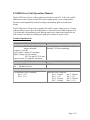
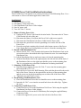
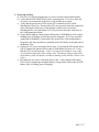
Operation Manual
S1145B Battery Pack
And
S1145R Power Unit
System Engineering
International
SEI Incorporated
5115 Pegasus Court
Suite Q
Frederick, Md 21704
Phone 301-694-9601
Fax
301-694-9608
Email [email protected]
Web
http//www.seipower.com
REV C
S1145B Battery Pack Operation Manual
Description
The S1145B is an improved direct replacement for the following Lucent/ATT ISDN
battery packs: 1147B1, 1148B1, 1149B1, and KS-21906. Features include 8 amp hour
battery capacity and compatibility with the existing wall mounting plate and connection
wiring.
The S1145B Battery Pack’s microprocessor-based controller monitors charge status and
automatically performs a periodic battery test to guarantee the holdover capability of the
pack. A Manual Battery Test Switch is also provided. The S1145B Battery Pack
provides LED indicators of the Battery Charge Status and the Battery Test Status.
The S1145B Battery Pack contains four 12 volt, 8 Amp-hour, sealed lead acid batteries,
connected in series to provide a nominal 48 Vdc. A panel-mounted fuse protects the
output.
Technical Specifications
Electrical
Environmental
Nominal Output Voltage: 48 Vdc
Temperature: -20°C to +40°C
Maximum Output Current: 6.00 A
Humidity: 95% non-condensing
Recommended Charge Voltage:54.0-56.4 Vdc
Rated Capacity: 8 Amp-hours @ C/20
Optimum battery life will be achieved if the
unit is operated at a temperature of 25°C.
LED Indicators
Battery Charge Status:
Constant Green – Fully Charged
Flashing Green – Charging
Constant Red – Power Unit Fault
Battery Test Status:
Constant Green – Battery Good
Fast Flash Red – Wait, Then Test
Slow Flash Red – Replace Battery
User Interface
Manual Battery Test Switch –Push to Test
NOTE: The Manual Battery Test switch is
disabled when the battery is charging. Also,
to prevent unnecessary battery discharge, the
Manual Battery Test is disabled for 5 minutes
following a Battery Test. In both cases, the
Wait, Then Test indication is displayed.
Fuse Replacement
3AG Fast-Acting 250V, 6.0A, Littlefuse Part Number 312 006 or Equivalent
CAUTION: For continued protection against risk of fire, replace only with the same
type and rating of fuse.
Page 1 of 7
S1145B Battery Pack Installation Instructions
The S1145B Battery Pack mounts on an existing Lucent/ATT Wall-Mounting Plate. For
a rack mount or a direct wall mount application, contact SEI regarding a BP-8U External
Battery Pack.
PARTS LIST
1) One S1145B Battery Pack
2) One Battery Connection Cable
1) Detach 1146B Distribution Unit (Skip to step 2 if there is no 1146B mounted next
to the Battery Pack)
a) Remove the #8-32x1” screw located at the bottom of the Distribution Unit, in
recessed area above the molded cable clips. Retain the screw for re-attaching the
Distribution Unit.
b) Lift the Distribution Unit up and out to remove it from the mounting plate
c) Slide the Distribution Unit to the right and place the left side hole on the back of
the Distribution Unit over the right most shoulder screw on the mounting plate.
This is a convenient way to hold the Distribution Unit during installation.
2) Remove Existing Battery
a) Disconnect the battery cord from the 1145 Power Unit’s right rear receptacle.
b) Loosen, but do not remove, the two #10-32x0.5” screws securing the Battery to
the Wall Mounting Plate.
c) Lift the Battery up and pull the battery away from the mounting plate.
3) Mounting S1145B Battery Pack
a) Place the Battery Pack on the mounting plate such that the metal hooks on the
back of the Battery Pack are in the square holes on the top of the mounting plate
and the screws are inside the mounting ears on both sides of the Battery Pack.
b) Tighten the two #10-32x0.5 screws.
4) Re-mounting 1146B Distribution Unit (Skip if no 1146B)
a) Place the Distribution Unit on the two shoulder screws on the mounting plate.
b) Insert the #8-32x1” screw into the recessed hole above the cable clips. Tighten
the screw.
5) Connecting S1145B Battery Pack
a) If the S1145B Battery Pack is used with a Lucent/ATT 1145 Power Unit, connect
the cable supplied with the S1145B Battery Pack to the connector on the right side
of the Battery Pack. Plug the other end of the supplied cable into the right rear
receptacle on the Power Unit.
b) If the S1145B Battery Pack is used with an SEI S1145R Power Unit, connect the
cable supplied with the S1145R Power Unit to the connector on the right side of
the Battery Pack. Plug the other end of the supplied cable into the receptacle on
the right side of the S1145R Power Unit.
6) Fuse Installation
a) Place the provided fuse into the fuse holder cap and insert the fuse into the fuse
holder, located on the right side of the unit. Secure the fuse holder cap with a
quarter turn.
Page 2 of 7
b) To prevent battery discharge, do not install the fuse in the S1145B Battery Pack
until the unit is ready to be connected to a Power Unit. Do not store the S1145B
Battery Pack with the fuse installed
7) Operational Test
The following operational test should be done on each unit immediately after
installation.
(The SEI S1145R Power Unit provides a continuous float charge voltage to the
battery. This allows the status indicators on the S1145B to be ON continuously.
The Lucent/ATT 1145 Power Unit provides an intermittent float charge voltage of
2 hours ON and 20 hours OFF. While the Lucent/ATT 1145 Power Unit is in
CHARGE ON mode the S1145B status indicators are ON continuously. When the
Lucent/ATT 1145 Power Unit is in the CHARGE OFF mode the S1145B status
indicators flash every 5 seconds.)
a) Normal Operation: Verify that the Battery Charge Status LED on the S1145B
Battery Pack is either flashing green (Charging), constant green (Fully Charged),
or flashing every 5 seconds. If either of the LEDs are constant red, flashing red or
are not lit consult the troubleshooting section below.
b) Battery Backup Operation: Make sure that the 1145B is properly connected to the
power unit. Disconnect the AC power cord from the power unit. Verify that both
LEDs flash every 5 seconds. The Battery Charge Status LED will indicate a
Power Unit Fault. (Depending on the load and Power Unit it may take several
minutes before the LEDs change state.) If an SEI S1145R Power Unit is being
used, verify that the Power Unit’s LED is constant red. If a Lucent/ATT 1145
Power Unit is being used, verify that the Power Unit’s Output Power On green
LED and On Battery Reserve red LED are lit.
c) Charging Operation: Reconnect the Power Unit AC power cord. Verify that the
Battery Charge Status LED on the S1145B Battery Pack is flashing green
(Charging). If an SEI S1145R Power Unit is being used, verify that the Power
Unit’s LED is constant green. If a Lucent/ATT 1145 Power Unit is being used,
verify that the Power Unit’s green Output Power On LED and yellow Charging
Battery LED are lit.
d) Battery Test: When the battery is fully charged (Battery Charge Status LED
constant green), press the Manual Battery Test switch. Wait five seconds then
verify that the Battery Test Status LED is green. (The Manual Battery Test is only
available when the Power Unit is charging the battery pack. If the Manual
Battery Test switch is pressed when the battery pack is not being charged, but the
battery pack voltage is above 49 volts, the Charge and Test status indicators light
for 2 seconds.)
8) Troubleshooting
a) Battery Pack LEDs Off: If the LEDs on the S1145B Battery Pack are not lit or
flashing every five seconds perform the following checks:
i) Verify that the Power Unit is on. On an SEI S1145R Power Unit, the LED
should be solid green. On a Lucent/ATT 1145 Power Unit, the green Output
Power On LED should be lit.
ii) Check the Battery Connection Cable at the Battery Pack connector and the
Power Unit Connector.
iii) Verify that the Battery Pack fuse is installed.
Page 3 of 7
iv) Verify that the Battery Pack fuse is not blown.
b) Power Unit Fault Indication: If the Battery Charge Status LED is constant or
flashing red, the Power Unit is not charging the Battery Pack at the recommended
charging voltage. The Power Unit should be replaced.
c) Replace Battery Indication: If the Battery Test Status LED is flashing red, the
holdover capability of the battery is significantly diminished. The battery should
be replaced.
9) Storage
The S1145B Battery Pack may be stored for periods of up to 6 months without
charging. For longer periods of storage, the S1145B Battery Pack should be
connected to a power unit until fully charged at least once every six months.
Warning: To prevent battery discharge, do not install the fuse in the S1145B
Battery Pack until the unit is ready to be connected to system power. Never store
the S1145B with the fuse installed.
Page 4 of 7
S1145R Power Unit Operation Manual
The S1145R Power Unit is a direct replacement for the Lucent/ATT 1145A, B1, and B2
ISDN power units. Features include 200 watts of output power, a low voltage battery
disconnect and compatibility with the existing wall mounting plate and connection
wiring.
The S1145R Power Unit provides a nominal 48 volt DC output voltage at up to 4.2 amps
with the ability to power up to 96 ISDN phones. Connectors are provided for power to an
1146 block and a backup battery pack. Backup batteries are connected in parallel to the
load so there is no delay in switching to backup power when AC power is lost.
Technical Specifications
Electrical
Environmental
Input Voltage: 120/240 Vac +10%/-15%
Operating Temperature: -20°C to +40°C
Jumper selectable
Humidity: 95% non-condensing
Frequency: 45-66 Hz
Input Current: 2 Amps AC maximum
Output Voltage: 48 Vdc nominal
42.5 Vdc min-55.2Vdc max
Output Current: 4.2 Amps DC maximum
LED Indicator
Green – On AC Power
Red – On Battery Power
Standards
UL1950
Connectors
Two Pin Battery Pack Connector
Pin 1 – (+V)
Pin 2 – (-V)
Eight Pin Power Connector
Pin 1 – Unused
Pin 3 – (+V)
Pin 5 – Unused
Pin 7 – Unused
Pin 2 - Unused
Pin 4 – (-V)
Pin 6 – Unused
Pin 8 – (-V)
Page 5 of 7
S1145R Power Unit Installation Instructions
The S1145R Power Unit mounts on an existing Lucent/ATT Wall-Mounting Plate. For a
rack mount or a direct wall mount application, contact SEI.
PARTS LIST
1) One S1145R Power Unit
2) One Battery Connection Cable
3) One Distribution Unit Power Cable Adaptor
4) One AC power cord
5) Two #10-32x0.5” Screws
1) Remove Existing Power Unit
a) Unplug the AC Power Cord from the electrical outlet. Disconnect the AC Power
Cord from the left side of the unit.
b) Disconnect the Battery Cord from the Power Unit’s right rear receptacle.
c) Disconnect the Distribution Unit Power Cable from the Power Unit.
d) Disconnect the ground wire from the grounding screw on the left side of the
Power Unit.
e) Press the two plastic retaining clips located at the bottom corners of the Power
Unit. Rotate the Power Unit up and out to remove it from the mounting plate.
2) Detach 1146B Distribution Unit
a) Remove the #8-32x1” screw located at the bottom of the Distribution Unit, in the
recessed area above the molded cable clips. Retain the screw for re-attaching the
Distribution Unit.
b) Lift the Distribution Unit up and out to remove it from the mounting plate.
c) Slide the Distribution Unit to the right and place the left side hole on the back of
the Distribution Unit over the right most shoulder screw on the mounting plate.
This is a convenient way to hold the Distribution Unit during installation.
3) Mounting S1145R Power Unit
a) Insert, but do not tighten, the two #10-32x0.5” screws into the mounting plate
holes labeled BATT 2.5/5.0.
b) Place the Power Unit on the Wall Mounting Plate such that the metal hooks on the
back of the Power Unit are in the square holes on the top of the mounting plate
and the screws are inside the mounting ears on either side of the Power Unit.
c) Tighten the two #10-32x0.5 screws.
4) Re-mounting 1146B Distribution Unit
a) Place the Distribution Unit on the two shoulder screws on the mounting plate.
b) Insert the #8-32x1” screw into the recessed hole above the cable clips. Tighten
the screw.
5) Connecting S1145R Power Unit
a) Connect the Power Unit to the Distribution Unit Power Cable using the supplied
Distribution Unit Power Cable Adaptor.
b) Connect the Power Unit to the S1145B Battery Pack using the supplied Battery
Connection Cable.
c) Connect the supplied AC power cord to the left side of the Power Unit.
Page 6 of 7
6) Power-up and Test
a) Power the S1145R by plugging the AC power cord into an unswitched outlet.
b) Verify that the LED on the Power Unit is constant green. If it is not, check the
AC power cord connection at the Power Unit and the power outlet.
c) Verify that the green power LEDs on the NT1s connected to the 1146B
Distribution Unit are on. If none of the NT1s are powered, check the connection
of the Distribution Unit Power Cable Adaptor at the Power Unit and the
Distribution Box. If an individual NT1 is not powered, check the connection at
the 1146B punchdown block.
d) Verify that the Battery Charge Status LED on the S1145B Battery Pack is either
flashing green (Charging) or solid green (Fully Charged). If it is not, check the
connection of the Battery Connection Cable at the Power Unit and the Battery
Pack and verify that a good fuse is installed in the fuse holder on the right side of
the Battery Pack.
a) Unplug the AC power cord on the Power Unit. Verify that the LED on the Power
Unit is constant red and the LEDs on the S1145B Battery Pack are off. Verify
that the NT1s are still powered. (Under very light load conditions, it may take
several minutes before the LEDs change state. The Battery Charge Status LED
on the Battery Pack will display constant or flashing red to indicate a Power Unit
Fault.)
e) Reconnect the AC power cord on the Power Unit. Verify that the LED on the
Power Unit is constant green and the Battery Charge Status LED on the S1145B
Battery Pack is flashing green (Charging).
Page 7 of 7