1
PRECAUTIONS
IMPORTANT! PLEASE READ
BEFORE PROCEEDING.
Following the important precautions below will help ensure you
many years of trouble free use from your CS1x.
LOCATION
• In order to avoid causing serious damage to
the CS1x, do not expose it to direct sunlight,
high temperatures, excessive humidity,
excessive dust or strong vibration.
• Always place the CS1x on a solid surface such
as a keyboard stand or a sturdy table or desk.
POWER SUPPLY
• Turn the power switch off when the CS1x is
not in use.
• Use only the supplied PA-3B or an equivalent
AC power adaptor. Use of an incompatible
adaptor may result in irreparable damage to
the CS1x, and could even pose a serious
shock hazard.
• The power adaptor should be unplugged
from the AC outlet if the CS1x is not to be
used for an extended period of time.
• Unplug the CS1x during electrical storms.
• Avoid plugging the CS1x into the same AC
outlet as appliances with high power
consumption such as electric heaters or
ovens. Also avoid using multiple-plug
adapters since these can result in reduced
sound quality and possibly even damage to
the instrument.
UNPLUG ALL INSTRUMENTS
WHEN MAKING CONNECTIONS
• To avoid causing damage to the CS1x and
other devices to which it is connected, such
as a sound system or MIDI instruments, turn
off the power and unplug all related devices
prior to connecting or disconnecting audio
and MIDI cables.
ELECTRICAL INTERFERENCE
• Avoid using the CS1x near televisions, radios
or other devices which generate
electromagnetic fields, since this may cause
the CS1x to malfunction, and possibly
generate interference noise in the other
devices.
diluted, mild detergent. Then wipe the
instrument thoroughly with a dry cloth.
• Avoid placing vinyl objects on top of the
instrument, since vinyl can stick to and
discolor the surface.
DATA BACKUP
BACK-UP BATTERY
• The CS1x contains a special long-life battery
that retains the contents of its User memory
when the power is turned off. The back-up
battery should last for several years. When it
needs to be replaced, the message "Battery
Low" will appear in the display when the
power is turned on. When this happens, have
the backup battery replaced by qualified
Yamaha service personnel. Do not attempt
to replace the backup battery yourself.
HANDLING AND TRANSPORT
• Always handle the CS1x with care. Physical
shocks caused by dropping, bumping, or
placing heavy objects on it can result in
serious damage to the CS1x.
• Yamaha recommends that you regularly save
your music data using an external MIDI data
storage device such as the Yamaha MDF2
MIDI Data Filer. Yamaha cannot be held
responsible for the accidental loss of CS1x
data.
SERVICE AND MODIFICATION
• The CS1x contains no user serviceable parts,
so never open the case or tamper with the
internal circuitry in any way. Doing so may
result in electrical shock or damage to the
instrument. Refer all servicing to qualified
Yamaha service personnel.
IMPORTANT NOTE
• Never apply excessive force to the controls,
connectors or other parts.
Yamaha cannot be held responsible for damage
to the CS1x resulting from improper handling
or operation, or for the accidental loss of CS1x
data.
• Disconnect all cables before moving the
CS1x. Always unplug cables by gripping the
plug firmly, and not by pulling on the cable.
NOTICES
CLEANING
• Never use chemical solvents or thinners to
clean the CS1x, since these will damage the
finish or dull the keys. Wipe the instrument
clean with a soft, dry cloth. If necessary, use
a soft, clean cloth slightly moistened with a
1
• The company names and product names in
this owner's manual are the trademarks or
registered trademarks of their respective
companies.
• The LCD screens as illustrated in this owner's
manual are for instructional purposes, and may
appear somewhat different from the screens
which appear on your instrument.
Introduction
In the beginning, there was the knob…
And the knob was good. Great, in fact.
You could just reach out and grab it. Turn it left. And turn it right.
Interact with it in realtime.
And there were knobs of all kinds. Knobs for changing the attack
and release times of a sound. Knobs for setting the cutoff filter and
resonance. And knobs for controlling many other aspects of analog
synthesizer sounds.
By twisting a knob one way and another, a vast, practically endless
variety of electronic sounds could be called forth. Fat sounds. Strange
sounds. Beautiful sounds. Magical sounds.
It was the 1960s, and such was the power of the knob that music
was changed forever.
And the term synthesizer became a household word.
But the knob was not perfect…
From the start the knob was brilliant and easy to grasp. It put the
musician in complete control of the sound. And opened up a whole
new world of sonic exploration.
It was the 1970s, and some of the greatest recordings in music history
were being made. Analog "synths" were finding their way into the stages,
studios and professional composing suites of the world.
But as simple, straightforward and powerful as analog synths were,
they were also for the most part priced out of reach of the struggling
musician. Plus they tended to be sensitive to slight fluctuations in electric
current which frequently wreaked havoc with pitch, thus making tuning
inherently unstable.
And there was no reliable way to save panel settings and original
sounds except for tediously scrawling lists and notes with pencil and
paper.
Surely there must be a better way.
Engineers the world over went to work searching for a better way,
and great strides were made in the development of more stable, lower
cost, and more convenient technologies.
A breakthrough in electronic sound synthesis was imminent.
Then came the miracle of digital…
The beginning of the 1980s saw breakthroughs in digital synthesizer
technology which was to once again revolutionize modern music.
Musicians everywhere embraced affordable new technologies like
FM, which could accurately reproduce the sound characteristics of
acoustic and other instruments, and AWM (PCM), which relied on
"samples" of actual instrument sounds to produce an amazing wealth
of musical textures and sonic options.
The new spate of digital synthesizers were—on the outside—much
more streamlined than analog synths, sporting a minimal array of buttons
and a display screen which provided information about each feature.
Overnight the knob was rendered virtually obsolete.
Unstable tunings were a thing of the past. Memory was the future.
Digital synths were—on the inside—more loaded than ever, as
hundreds of amazing acoustic and electronic sounds, or voices, could
be stored and recalled at the touch of a button. Scores of new and exciting
features were available. Entire panel settings and configurations could
also be stored for instant recall.
It was the digital revolution that made MIDI, GM, XG, sequencing,
sampling, looping, multitimbral play, DSP effects and many other
breakthroughs in electronic music technology possible.
Developments that have changed forever the way we teach, compose,
2
perform and listen to music.
Global design standards ensured that music hardware and software
products made by different manufacturers could work together
seamlessly.
But alas, digital did not create a perfect world.
on the panel.
A collection of six rotary Sound Control Knobs are irresistible to the
touch—and provide instant sonic results when turned.
Between the Sound Control Knobs, the clearly labeled panel switches,
and the back lit LCD, the current status of the CS1x is always crystal
clear.
The numeric keypad and other buttons—including Scenes, or
"snapshots" of knob positions—give you quick and easy access to any
parameter or setup you need, the moment you need it.
As such, the CS1x is an unprecedented realtime performance
instrument.
The hundreds of great sounding AWM2 (Advanced Wave Memory
2) instrument voices (created from high quality recordings of actual
instrument and other sounds), three digital effects units (with 11 Reverb,
11 Chorus and 43 Variation type effects) and scores of other parameters
can be configured in an almost unlimited variety of ways and stored in
memory for instant recall.
Performances, or complete configurations of up to four Layers
(voices) playing simultaneously, plus effect and other parameters, and
Multis, or a configuration of up to 16 Parts and other parameters for
multitimbral play (using an external sequencer or computer), provide a
unique array of options which make the CS1x a handy synth for literally
any type of music situation.
Thirty-two notes of polyphony ensure that you always have enough
available notes to play even the most demanding arrangement.
The on-board arpeggiator which can generate various types of
automatic arpeggios or be controlled by an external MIDI clock provides
an extremely useful tool for spicing up your masterpieces—or setting
the dance floor on fire.
Chaos reigned over the land…
As convenient, dynamic and accessible as digital synthesis was, still
it was not perfect. It had certain limitations, though different ones than
analog synthesis.
Streamlined panel layouts and the demise of the knob meant that
all those hundreds of great new features had to be organized and stacked
in pages and subpages of hidden menus—which might mean several
presses of one or more buttons just to find a feature, and several more
to actually manipulate it.
And the steep learning curve of many digital synthesizers became a
legend unto itself. Alarmingly, the synth was on its way to becoming a
thing of science, rather than an intuitive musical instrument.
It was, therefore, inevitable that many would come to mourn
nostalgically for the days of simplicity—for the knob. For those warm,
fat, wonderful analog sounds. For fewer hidden features.
And for a simpler, easier to use electronic instrument.
There was a definite need for an analog-style digital synthesizer
that would have intuitive knobs plus all the benefits of digital memories
and other convenient—especially interactive—features.
One that could satisfy even the most die-hard advocate of analog or
digital synthesis.
A perfectly versatile synthesizer as attractive to first-time synth
owners as to desktop music hobbyists, serious amateurs, and even
seasoned professionals.
A powerful stand-alone performance instrument with hot dance
music and other versatile voices, as suited for the cutting edge as for the
classics.
An ideal multitimbral MIDI component which could fit right into
even the most sophisticated expanded system.
One with extremely modest pricing for such powerful utility.
It was only a matter of time before the thunder of analog would
unite with the lightning of digital to once again challenge convention
and ultimately change the landscape of music possibilities yet once more.
Go forth and multiply…
As simple—yet powerful—as the CS1x is on its own, it has also
been specially engineered to easily fit right into any type of expanded
music system you wish to create.
General MIDI (GM) compatibility makes the CS1x an ideal
multitimbral tone generator for accurately playing any of the many
Standard MIDI File or other commercially available GM music data using
an external sequencer.
XG compatibility makes the CS1x completely state of the art—
conveniently able to take advantage of the expanded sound and
expressive capabilities that this exciting new format will offer in the
coming months and years.
A TO HOST terminal and HOST SELECT switch provides for direct
interface with either PC and Macintosh computers, thus enabling you
to easily jump right into the "desktop music" revolution without the
need for any additional peripheral interfacing equipment.
If you're a first-time synthesizer owner, the CS1x lets you expand
your music system at your own pace.
First you might want to add an affordable Yamaha QY series
sequencer and take advantage of the CS1x's powerful multitimbral
capabilities. With a QY sequencer you can record and play back up to
16 music "parts", each on an independent MIDI channel—just like a
multitrack recorder, but with virtually unlimited editing capabilities.
Next you might want to add the compact, low-cost Yamaha SU10
sampler which lets you capture music phrases and other sounds to add
an entirely unique dimension to your music.
Finally you might want to add a computer which will let you take
advantage of the many different types of music software products now
available plus those yet to come.
With the CS1x at the heart of your system, you're ready to grow
your own unique music system and take your musical capabilities as far
as you want—naturally.
And Yamaha heard their cries…
Fortunately Yamaha recognized that something new and significant
must be created to bring together the best of both analog and digital
worlds.
The result was the Yamaha Control Synthesizer CS1x.
The CS1x takes the best of analog—simplicity of use, natural
interactivity, thick sound, and, of course, the knob—and unites it with
the best of digital—reliable pitch, plenty of memory, one-touch setting
reconfigurations, hundreds of voices, MIDI, and much, much more—
to begat a truly unique "control" synthesizer.
One with all the familiar concepts loved by both analog and digital
afficianados. One destined to satisfy even the most meticulous purist in
each camp.
Nothing to hide…
Perhaps the most striking—certainly refreshing—aspect of the CS1x
Control Synthesizer is the way it wears its heart on its sleeve.
What you see is what you get: all features are self-evidently displayed
3
CS1x MAIN
FEATURES
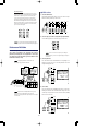
The CS1x is specially designed with an intuitive, interactive user interface
through lots of dedicated panel controls and sound editing features which
can easily be manipulated in realtime during performance. Main features
include:
• 6 Sound Control Knobs for direct access to key parameters of the currently
selected voice as you play, and 2 Scene memories for instant recall of
specified Sound Control Knob positions. You can use the Modulation
Wheel or a connected Foot Controller for continuous changes between
Scene 1 and Scene 2 parameter values.
• 480 GM- and XG-compatible AWM2 instrument voices and 11 drum
voices, or kits, in Multi Play mode. Additional voices are available in
Performance mode which can be assigned to the Performances.
• Performance mode with complete configurations of Layers (4 voices either
stacked or in sophisticated keyboard and velocity splits), digital effects
and other parameters. There are a total of 128 Preset Performances and
128 User Performances.
• Multi Play mode for multitimbral play of up to 16 different Parts (across
16 MIDI channels; when using an external sequencer), with 32-note
polyphony. TO HOST terminal and HOST SELECT switch allow direct
interface with IBM PC/AT or Apple Macintosh computers.
• 3 independent DSP digital effect units which can be used simultaneously—
Reverb (11 types), Chorus (11 types) and Variation (43 types).
• Arpeggiator with 30 types of arpeggiated chords and 10 timing subdivisions.
The Arpeggiator's tempo can also be controlled by an external MIDI
clock.
4
CONTENTS
The CS1x At A Glance .....................................6
Getting Started ............................................9
How The CS1x Generates Sound ................... 12
CS1x Main Operating Modes ........................ 14
Feature Reference ............ 20
Performance Mode .....................................20
Common Edit 1 ........................................ 22
Common Edit 2 ....................................... 25
Layer Edit 1 ............................................. 27
Layer Edit 2 .............................................30
Layer Edit 3 ............................................. 31
Layer Edit 4............................................. 33
Multi Play Mode.......................................... 36
Utility Mode ...............................................40
Store Mode .................................................44
Factory Settings .........................................46
Appendix ............................. 47
Digital Effects ............................................ 47
About MIDI ................................................. 53
Specifications ............................................. 57
Troubleshooting ......................................... 58
Error Messages ........................................... 59
Index..........................................................60
5
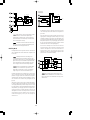
THE CS1x AT A
GLANCE
PHONES
L/MONO
R
DC IN
POWER
OUTPUT
FOOT
FOOT
FOOT
VOLUME CONTROLLER SWITCH
INPUT
TO HOST
HOST SELECT
IN
OUT
THRU
MIDI
ARPEGGIATOR
TEMPO
TYPE
P BEND
RANGE
NOTE
SFT
VWX
PERFORMANCE
AMP EG
VOLUME
MULTI
ATTACK
RELEASE
ASSIGN 1/DATA
ARPEGGIO HOLD
STORE
UTILITY
SHIFT
+
PART/LAYER/ OCTAVE
2
MW/FC
PRESET
+
8
9
PQR
STU
4
5
6
DEF
GHI
JKL
1
2
3
PRESET USER ARPEGGIATOR
CUTOFF
RESONANCE
SPACE
0
PROGRAM
FILTER
PITCH
7
MNO
REV
TYPE
EFECT
VARI
TYPE
FMOD
CHO
TYPE
FC
CUTOFF
LIMIT
HIGH
LIMIT
LOW
LIMIT
HIGH
SUS
LEVEL
REL
TIME
AMOD
PMOD
FMOD
ATK
LEVEL
CUTOFF
NOTE
VARI
VARI
PARAM
DATA
PORTA
SWITCH
TIME
VARI
EF
VEL
OFFSET
DEPTH
AEG
*&
ABC
USER
1
SCENE
YZ'
PERFORM
LEVEL
LIMIT
LOW
SUB
DIVIDE
MW
FMOD
PMOD
TUNE
DETUNE
ATK
TIME
DCY
TIME
PERFORM
NAME
ASSIGN1
PARAM
COMMON
ASSIGN2
PARAM
DATA
LFO
FEG
WAVE
SPEED
PHASE
INIT
PEG
ATK
TIME
DCY
TIME
SUS
LEVEL
REL
TIME
INIT
LEVEL
BANK
PROGRAM
VOLUME
PAN
REV
SEND
ATK
TIME
EFFECT
CHO
SEND
VEL
FIX
TRANS
CH
RCV
CH
VARI
SEND
DCY
REL
TIME
TIME
FILTER
CUTOFF
REZ
LAYER
REL
LEVEL
POLY/
MONO
DEMO
PERFORMANCE
MULTI
STORE
UTILITY
ENTER
NO/
QUICK PC
ASSIGN 2
YES
MASTER
TUNE
SYSTEM
KBD
VEL
CURVE
TRANS
MIDI
DEVICE
NO
LOCAL
BULK
DUMP
ASSIGN
CTRL
NO
UTILITY
MODULATION
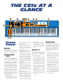
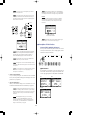
Front
Panel
! VOLUME
Turn this knob to set the proper
listening level whether using
headphones or amplified speakers.
" SOUND CONTROL
KNOBS
The six Sound Control Knobs give
you direct access to key parameters
of the currently selected
Performance/voice. Turning any
Sound Control Knob to the left or
right will offset the parameter values
accordingly (left for negative values,
right for positive values) and
produce an immediate result; a letter
"E" will appear next to the
Performance number in the LCD to
indicate the original voice has been
edited. Each knob has a center
detent which represents the original
value of the parameter.
• ATTACK (Knob 1) - This knob
controls the initial attack time of the
voice. Turn it left for a faster attack
time; turn it right for a slower attack
time. (See page 30)
• ASSIGN 2 (Knob 6) - This knob can
be used to control any one of 28
parameters which you can assign to
it—including Volume, Note Shift,
Pan, Chorus Send, and others. (See
page 29.)
• RELEASE (Knob 2) - This knob
controls the release time of the voice.
Turn it left for a shorter release time;
turn it right for a longer release time.
(See page 32.)
# SCENE 1 & 2
• ASSIGN 1/DATA (Knob 3) - This
knob has two functions. As an
ASSIGN 1 knob, you can assign one
of 28 parameters—including
Performance Volume, Arpeggiator
Tempo or Type, Portamento Time,
and others—to control by turning it
(see page 26). As a DATA entry knob,
you can use it to quickly change the
edit value of the currently selected
edit parameter.
Each Performance has two Scene
memories which remember specific
positions of the six Sound Control
Knobs. (See page 16.)
• Simply press SCENE 1 or SCENE 2
to instantly recall the specified
settings. An LED beside each SCENE
button will light to indicate which
Scene is currently active. You can
store your own Scenes in advance
using Store mode. (See page 44.)
• CUTOFF (Knob 4) - This knob
determines the cutoff frequency of
the filter, or the frequency point
above which other frequencies are
filtered out. Turn it left for a deeper,
more rounded tone; turn it right for
a thinner, brighter tone. (See page
25.)
• By holding one SCENE button and
then pressing the other SCENE
button, both LED's will light,
indicating that you can use the
Modulation Wheel or a connected
Foot Controller for realtime
continuous parameter changes
between one Scene and the other.
(See page 45.)
• RESONANCE (Knob 5) - This knob
determines the amount of filter
resonance or emphasis of the cutoff
frequency. Turn it left to produce a
relatively flat response; turn it right
to add overtones and make the
sound more resonant. (See page 34.)
6
$ ARPEGGIATOR
Press this button to activate the onboard Arpeggiator, which lets you
create automatic arpeggios simply
by playing a chord. An indicator will
appear in the lower right area of the
LCD when the Arpeggiator is on.
(See page 22.)
• There are various Arpeggiator Types
and Arpeggiator Timing
Subdivisions. These, plus the
Arpeggiator Tempo, can be specified
with the Common Edit 1 menu
parameters. (See page 23.)
• Pressing this button while holding
SHIFT will "hold" the arpeggiated
chord, or make it continue playing
even when you release the keys.
Pressing this button again stops the
Arpeggiator. (See page 23.)
• An Arpeggiator Split function lets you
split the keyboard at C3; the chords
you play to the left of the split point
will create arpeggiated chords, and
the notes and chords you play to the
right of the split point will play as
normal. (See page 23.)
% SHIFT
This button lets you transpose the
octave up or down as well as
activate the Arpeggiator Hold and
Split functions. (See page 23.)
• To transpose the octave, hold the
SHIFT button and press [–] (octave
down) or [+] (octave up)—located
directly beneath the SHIFT button.
(See page 15.)
& PART/LAYER [–]/[+]
These buttons let you select one of
the four Layers in Performance
mode (see page 14), or one of the
16 Parts in Multi Play mode (see
page 17). Which Layer or Part is
currently selected will be indicated
in the lower right area of the LCD.
' PRESET
In Performance mode, press this
button to activate the bank of 128
Preset Performances. (See page 20.)
( USER
In Performance mode, press this
button to activate the bank of 128
User Performances. (See page 20.)
) PROGRAM [–]/[+]
Press one of these to step up ([+]) or
down ([–]) through each
Performance (in Performance mode)
or voice (in Multi Play mode), one
at a time. (See page 20.)
* BACK LIT LCD
Performance (Performance mode)
or voice (Multi Play mode) within
the currently designated group of
10—by simply punching in the last
digit (0~9) of the desired
Performance or voice number. (See
page 21.)
• When naming a User Performance,
you can use it to select the letters of
the name, as indicated above each
button. (See page 24.)
, [–]/NO/QUICK PC
• As a [–] button, you can use it to
enter negative values when editing
parameters using the numeric
keypad. Press it before entering the
number, followed by ENTER.
• In Performance mode or Multi Play
mode, press it once to engage the
Quick Program Change function.
The hundredth and tenth digits of
the Performance or voice number
will be shown as bold characters
to indicate they are fixed when
Quick Program Change is active.
Press the button again to turn off
Quick Program Change. (See page
21.)
The numeric keypad has several
functions, depending on the
currently selected mode.
• In Performance mode or Multi Play
mode, you can use it to select a
specific Performance number or
voice number—by punching in the
desired number (1~128), then
pressing the ENTER button. (See page
20.)
• UTILITY - Press this button to access
those "system" parameters which
affect the CS1x as a whole—such as
Master Tune, MIDI Transmit and
Receive Channel numbers, Local
On/Off, etc.—as printed directly
below each Parameter Value UP/
DOWN button. (See page 40.)
/ EDIT PARAMETER
ROTARY SWITCH
- ENTER/YES
This button has three functions.
+ NUMERIC KEYPAD
These ten buttons are used to access
specific parameters in Performance,
Multi and Utility modes, as well as
change the values of the currently
selected edit parameter.
• STORE - This button lets you store
User Performances. as well as
Scenes. (See page 44.)
• In Store mode, this button lets you
decline (NO) the store operation if
you change your mind.
• When designating edit parameter
values using the numeric keypad,
you must press ENTER to activate
the change. (See page 22.)
Press one of these to select the
current operating mode.
• MULTI - Press this button to enter
Multi Play mode, which lets you
designate up to 16 Parts for
multitimbral play when using an
external sequencer. Parameters
which can be edited in Multi Play
mode are printed in a row directly
above the Parameter Value UP/
DOWN buttons. (See page 36.)
This button has three functions.
• When selecting a Performance
number (Performance mode) or
voice number (Multi Play mode)
using the numeric keypad, you
must press ENTER to activate the
change. (See page 20.)
0 PARAMETER VALUE
UP/DOWN BUTTONS
• PERFORMANCE - In Performance
mode you can choose any of the
Preset or User Performances, plus
perform editing operations using the
Edit Parameter Rotary Switch and
Parameter Value UP/DOWN
buttons. Press PERFORMANCE to
enter Performance mode from
another mode, or to reselect the
Performance select screen in the
LCD after performing an edit
operation in Performance mode.
(See page 20.)
• When editing parameters, you can
use it to quickly select a specific
value—by punching in the desired
number, then pressing ENTER. (See
page 20.)
The LCD provides various types of
information which clearly indicates
the current operating status of the
CS1x, depending on which mode
or other button on the front panel
that you press.
. MODE SELECT
SWITCHES
Turn this knob to select one of the
six menus of edit parameters in
Performance mode.
• COMMON - The Common
parameters (Common Edit 1, 2
menus) are those parameters which
apply to the entire currently selected
Performance; i.e., it doesn't matter
which Layer is currently selected,
since common parameters (except
for Portamento) apply to all layers
equally. (See page 14.)
• In Store mode, this button lets you
confirm (YES) the store operation.
(See page 44.)
• LAYER - The Layer parameters (Layer
Edit 1, 2, 3, 4 menus) are those
parameters which affect only the
currently selected Layer (1~4, as
designated by the PART/LAYER
buttons) in a Performance. (See page
14.)
• In Quick Program Change mode,
you can use it to select a specific
7
• PERFORMANCE MODE - After
selecting an Edit menu row with the
Edit Parameter Rotary Switch, press
the Parameter Value UP/DOWN
button located beneath the desired
parameter once to access the
parameter. The parameter name and
current value will appear in the LCD.
Then press [UP] or [DOWN] to
increase or decrease the current
parameter value as desired. (See
page 14.)
• MULTI PLAY MODE - Simply press
the Parameter Value UP/DOWN
button located beneath the desired
parameter as printed on the panel,
directly above each button. The
parameter name and current value
will appear in the LCD. Then press
[UP] or [DOWN] to increase or
decrease the current parameter value
as desired. (See page 17.)
• UTILITY MODE - Simply press the
Parameter Value UP/DOWN button
located above the desired parameter
as printed on the panel, directly
below each button. The parameter
name and current value will appear
in the LCD. Then press [UP] or
[DOWN] to increase or decrease the
current parameter value as desired.
(See page 40.)
1 PITCH
The Pitch Wheel lets you bend the
pitch up or down as you play. It is
spring-loaded to automatically
return to center position when you
let go of it. In Performance mode
you can designate the Pitch Bend
Range in the Common Edit 2 menu.
(See page 25.)
2 MODULATION
The Modulation Wheel lets you
apply or set a designated amount of
vibrato or tremolo. You can set it to
affect filter cutoff, filter modulation,
pitch modulation (Common Edit 2
menu, see page 25), as well as other
controllable parameters. (see page
43.)
THE CS1x AT A GLANCE
MIDI
THRU
OUT
IN
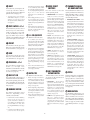
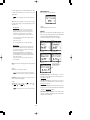
Rear
Panel
! MIDI
MIDI IN, OUT and THRU terminals
let you connect other MIDI devices
such as a MIDI keyboard, tone
generator, sequencer, or computer
with a MIDI cable. (Set the HOST
SELECT switch to MIDI when using
the MIDI terminals.) MIDI IN is for
input of MIDI data. MIDI OUT is
for output of MIDI data and for data
dumps to another CS1x or MIDI data
storage device. MIDI THRU is for
"daisy-chain" connection of
additional MIDI instruments, as the
MIDI data received at the CS1x's
MIDI IN terminal is passed along
unchanged to the CS1x's MIDI
THRU terminal. (See page 9.)
" HOST SELECT
The HOST SELECT switch lets you
designate the type of host computer.
(See page 10.) Set it to MIDI for
normal MIDI transmission and
reception when a host computer is
not connected.
HOST SELECT
PC-2 PC-1
MIDI
Mac
ASSIGNABLE
TO HOST
INPUT
FOOT
FOOT
FOOT
SWITCH CONTROLLER VOLUME
# TO HOST
POWER
ON
OFF
Variation effect (Common Edit 2
menu, see page 26), as well as the
Control Change Number. (see page
43.)
The TO HOST terminal lets you
connect the CS1x directly to a host
computer which does not have a
MIDI interface. (See page 10.)
' FOOT VOLUME
$ INPUT
An optional Yamaha FC7 or FC9
foot controller connected to this jack
can be used to regulate overall
volume.
Connect an external audio source
(such as a keyboard, or CD player)
here using either a stereo or mono
mini plug, in order to mix its audio
signals with the CS1x's voices, for
output from the CS1x without the
need for an external mixer.
( POWER
Press this switch to turn the CS1x
on and off.
% FOOTSWITCH
) DC IN
An optional Yamaha FC4 or FC5
footswitch connected to this jack
can be used to control hold on/off,
portamento on/off and others,
determined by the Assign Control
Change Number setting in Utility
mode. (see page 43.)
Connect the supplied Yamaha PA3B Power Adaptor here.
(CAUTION: Do not attempt to use
an AC adaptor other than the
Yamaha PA-3B or equivalent, since
the use of an incompatible adaptor
may cause irreparable damage to
the CS1x, and may even pose a
serious shock hazard.)
& FOOT CONTROLLER
An optional Yamaha FC7 or FC9
foot controller connected to this jack
can be used for control of filter
modulation, filter cutoff, and the
8
OUTPUT
DC IN
R
PHONES
L/MONO
* OUTPUT
The stereo OUTPUT jacks let you
connect the CS1x to an external
stereo amplifier/speaker system.
When using a mono system,
connect it to the L/MONO jack.
+ PHONES
The PHONES jack lets you connect
a set of stereo headphones for
private listening.
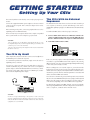
GETTING STARTED
Setting Up Your CS1x
The Control Synthesizer CS1x literally comes ready to play right out of
the box.
The CS1x With An External
Sequencer
Connect the supplied PA-3B DC power adaptor to the CS1x's DC IN
connector on the rear panel. Then connect the adaptor to the nearest
electrical outlet.
The illustration below shows how to use the CS1x with a Yamaha QY
series sequencer, which lets you take full advantage of the CS1x's
multitimbral capability to play up to 16 different musical instrument Parts
at once.
Before switching on the power, connect any peripheral devices such as
amplified speakers or MIDI instruments.
You will need MIDI cables to make the proper connections.
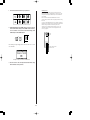
There are many ways to incorporate the CS1x into a simple or expanded
music system. Below are a few examples to get you started.
1. Connect a MIDI cable from the CS1x's MIDI OUT terminal to the
sequencer's MIDI In terminal, and connect another MIDI cable from
the CS1x's MIDI IN terminal to the sequencer's MIDI Out terminal.
CAUTION
2. Set the HOST SELECT switch to MIDI.
• Do not attempt to use an AC adaptor other than the PA-3B. Use of an
incompatible adaptor may result in irreparable damage to the CS1x, and
could even pose a serious shock hazard.
HOST SELECT
PC-2 PC-1
MIDI
Mac
• Be sure to disconnect the power adaptor from the electrical outlet when
the CS1x is not in use.
MIDI IN
MIDI OUT
MIDI QY300 etc...
OUT
QY300
The CS1x By Itself
MUSIC SEQUENCER
MIDI IN
CS1x
At the simplest level, all you need to do is connect stereo headphones to
the PHONES jack located on the rear panel.
In this case, the notes you play on the keyboard will be sent as MIDI note
event data to a specified MIDI channel of the sequencer. By selecting
different channels, you can record each Part independently, while listening
to those Parts you've already recorded.
As a stand-alone performance instrument, simply connect the CS1x to
amplified speakers, as follows:
For stereo use, connect one end of a pair of audio cables to the CS1x's
OUTPUT (L/MONO, R) jacks, and the other end to each amplified
speaker's input, as shown in the illustration below. (For mono use, connect
one end of a single audio cable to the CS1x's L/MONO jack, and the
other end to the amplified speaker's input.)
When recording Parts to an external sequencer, you need to turn the
keyboard Local setting to OFF (see page 42). When keyboard Local is
turned off, the notes you play on the keyboard will not sound the CS1x's
internal tone generator, but note and other performance event data will
still be sent from the MIDI OUT terminal.
Since the CS1x's internal tone generator will respond to note and other
data it receives at the MIDI IN terminal, the notes you play on the keyboard
will be sent to the sequencer, then "echoed back" to the CS1x to play one
of the 16 Parts (depending on the current MIDI channel assignment).
AMPLIFIED
SPEAKERS
L
PHONES
L
R INPUT
For details about assigning CS1x MIDI channels, see page 41. For details
about assigning MIDI channels and other settings for the external devices
such as a sequencer, consult the owner's manual of each.
R OUTPUT
CS1x
CAUTION
In order to avoid possible damage to the speakers or other connected
electronic equipment, before switching on the power of any component,
make sure the CS1x's volume level and the volume levels of the connected
equipment are set to minimum.
9
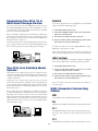
Connecting The CS1x To A
MIDI Data Storage Device
Macintosh
If you have an Apple Macintosh not equipped with an external MIDI
interface, perform the following operation:
You can also connect the CS1x with a MIDI data storage device, such as
the Yamaha MDF2 MIDI Data Filer in order to "bulk dump", or save a
User Performance ("1 Perf" setting) or all the User Performances and Utility
parameters ("All" setting) to floppy disks.
1. Set the HOST SELECT switch to Mac.
2. Connect the TO HOST terminal on the CS1x to the Modem or
Printer port on the Macintosh.
This lets you build up complete libraries of Performance and other data,
which you can easily load back into the CS1x. (The MDF2 also lets you
play compatible song data on the CS1x directly from the MDF2 itself,
without the need for a sequencer.)
3. Turn on the host computer, then turn on the CS1x.
4. Start up your music software, and set up the appropriate options
in the software for operation with the CS1x.
For information about how to perform Bulk Dump operations with the
CS1x, see page 42. Refer to the owner's manual of the MIDI data storage
device for operating instructions about sending and receiving data.
The options you may have to set for the Apple MIDI Driver settings:
MIDI Interface Type (Clock) ➛ 1 MHz
HOST SELECT
PC-2 PC-1
MIDI
Mac
MIDI IN
Other options and settings may have to be made as well. Refer to the
owner's manual of your particular music software for more information.
MDF2 etc...
MIDI OUT
MIDI
OUT
IBM PC and Clones
MIDI
MDF2
MDR
SEO
JOB
UTIL
If you have an IBM PC/AT or compatible computer not equipped
with an external MIDI interface, perform the following operation:
MIDI DATA FILTER
CURSOR
- FILE DATA +
REC
PAUSE
START/STOP
TEMPO
MIDI IN
CS1x
1. Set the HOST SELECT switch to PC-2.
The CS1x In A Desktop Music
System
2. Connect the TO HOST terminal on the CS1x to one of the
computer's serial ports, COM 1 or COM 2.
With its built-in host computer interface the CS1x is designed for direct
connection to an Apple Macintosh, IBM PC/AT or NEC PC-9800 Series
computer—without the need for a special MIDI interface between the
computer and the CS1x.
3. Turn on the host computer, then turn on the CS1x.
4. Start up your music software, and set up the appropriate options
in the software for operation with the CS1x.
Using the CS1x in a computer music system lets you receive the full
benefits of the instrument's true capabilities, as well as take advantage of
the ever-expanding world of available music sequencer and other software
products which provide you with unlimited potential to achieve your
personal music goals.
Refer to the owner's manual of your particular music software for
more information.
MIDI/Computer Connecting
Cables
If your computer already has a MIDI interface installed, you may want to
use it rather than using the host computer interface on the CS1x. Otherwise,
depending on the computer or interface used, set the HOST SELECT
switch to the appropriate setting: MIDI, PC-1 (NEC PC-9800 Series), PC2 (IBM and clones), or Mac (Macintosh). For information on the types of
cables that can be used for connection, see the section MIDI/Computer
Connecting Cables, at right.
MIDI
Standard MIDI cable, maximum length 15 meters.
Mac
Apple Macintosh Peripheral cable (M0197), maximum length 2 meters.
HOST SELECT
PC-2 PC-1
MIDI
Mac
Connecting Cables
PC-1
TO HOST
8-pin MINI DIN to D-SUB 25-pin cable, maximum length 1.8 meters.
(If your PC-1 type computer has a 9-pin serial port, use the PC-2 type
cable.)
CS1x
Computer
PC-2
8-pin MINI DIN to D-SUB 9-pin cable, maximum length 1.8 meters.
10
Switching On
The Power And
Producing
Sound
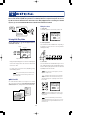
Playing
Arpeggiated
Chords
Take a moment and try out the Arpeggiator function, which creates
automatic arpeggios based on the chords you play. First select a
Performance with a fast attack, such as a percussive type sound. (Note:
The Arpeggiator function only works in Performance mode.)
Once all connections have been properly made, you're ready to switch
on the power and start having fun with the CS1x.
1. Turn the volume of the CS1x to its minimum position.
1. Press ARPEGGIATOR. An indicator will appear in the lower right
area of the LCD.
2. Press the POWER switch, located on the rear panel.
2. Play a chord. The arpeggiated chord will begin playing, based on the
Arpeggiator Type, Tempo and Subdivide parameter settings.
3. After a brief greeting message, the CS1x will power up.
4. Gradually turn the VOLUME knob to the right while playing the
keyboard until you achieve a comfortable listening level.
3. Change the Arpeggiator Type, Tempo and Subdivide parameters using
the Common Edit 1 menu. (See page 22.)
Playing The
Demo Songs
ARPEGGIO HOLD
SHIFT
+
Before you dive in and start exploring the many Performances and other
versatile features of the CS1x, you may want to listen to the preprogrammed
demonstration song.
PART/LAYER/ OCTAVE
PRESET
USER
+
The Demo provides a dynamic example of just how powerful the CS1x
really is. To play the Demo, perform the following operation:
PROGRAM
Arpeggiator Hold
The handy Arpeggiator Hold function lets you play a chord to start the
automatic arpeggio, then take your hand off the keyboard—the arpeggiated
chord will play continuously in a loop. Play another chord and the
automatic arpeggios will change accordingly.
1. In Performance mode, hold the PERFORMANCE button and press
the MULTI button.
2. The word "DEMO" will appear in the LCD, and after a brief moment
the Demo song will begin, and continue playing.
3. To stop the Demo, simply press a mode button, such as
PERFORMANCE.
1. Hold SHIFT and press ARPEGGIATOR. The Arpeggiator indicator in
the LCD will start blinking.
2. Play a series of chords.
3. To stop the arpeggiated chords, press ARPEGGIATOR again.
Arpeggiator Split
The Arpeggiator Split function greatly increases the performance capability
of the CS1x. When Arpeggiator Split is engaged, any chord you play to
the left of the split point (B2 and below) will produce an arpeggiated
chord, while chords you play to the right of the split point will play
normally.
DEMO
PERFORMANCE
MULTI
STORE
UTILITY
When the Demo mode is engaged, you can select a Demo song from the
various Demo songs using the numeric keypad.
1. Press ARPEGGIATOR to activate the Arpeggiator function.
2. Set the Edit Parameter Rotary Switch to the Common Edit 1 menu.
3. Hold SHIFT and press the left-most Parameter Value UP/DOWN
button (Arpeggiator Type parameter).
11
4. Pressing [UP] will turn on the Arpeggiator Split feature (the letter "S"
will display in the LCD); pressing [DOWN] will turn it off.
How The CS1x
Generates Sound
Oscillators, Filters And
Amplifiers
In order to better understand what's actually happening to the sound as
you turn the Sound Control Knobs or modify other parameters, it is helpful
to first take a look at the key components which make up the physical
nature of sound.
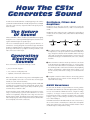
Synthesizers rely on three key electronic components to imitate the
soundwaves of musical instrument voices, as well as create entirely new
sounds.
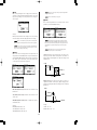
The Nature
Of Sound
In traditional analog synthesis the source sound pitch is generated by an
oscillator, its tone is created by a filter, and its volume is determined by
an amplifier.
What is sound? If we could see sounds they would look like waves rippling
through the air at a constant speed with high frequencies bunched close
together and lower frequencies spread far apart.
Our ears are naturally designed to take these physical vibrations—or
sound waves—moving through the air around us at high, mid and low
frequencies, and interpret them as a dog barking across the street, someone
practicing a violin next door, a jet airplane screaming overhead, or rock
music on the stereo in front of you.
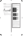
OSCILLATORS
FILTERS
AMPLIFIERS
GENERATES
PITCH
CREATES
TONE
DETERMINES
VOLUME
! The oscillator generates sound wave vibrations at controllable speeds,
or frequencies, to create pitch. Synthesizer oscillators usually offer a
range of frequencies between 20 Hz and 20kHz, which is the range
of the audio spectrum that most human beings can hear. They also
usually offer various types of sound waveforms, such as sine, sawtooth,
and others.
Generating
Electronic
Sounds
" Musical instrument sounds are made up of the basic tone that we
clearly distinguish, plus additional harmonics, or overtones which
exist at each octave above the basic tone, but that we cannot distinctly
hear. The filter provides control over these harmonics. By manipulating
the filter's cutoff frequency, which decides where to delete—or cut
off—the overtones, and resonance settings, you can thus determine
the tone.
There are three basic elements which make up a sound:
• pitch, or how low or high it is
• tone, or what its overall quality is like
• amplitude, or how loud its volume level is
# An amplifier controls the volume of the tone. An envelope generator
(EG) determines the tone's volume over time, through attack, decay,
sustain and release settings.
Before we take a look at how the CS1x generates and manipulates pitch,
tone and amplitude, lets first take a look at how these elements apply
naturally to acoustic musical instruments.
Acoustic musical instruments are specifically designed and carefully built
to produce precise sound characteristics when played—which is why a
violin always sounds like a violin, a piano always sounds like a piano,
and a flute always sounds like a flute.
AWM2 Waveforms
The CS1x takes the familiar concepts and functions of analog synthesis
and combines them with the state of the art in digital synthesis technology.
A musician playing a finely crafted violin will scrape the bow across the
string at a certain intensity to generate violin sound waves at a certain
volume level (amplitude), and produce low or high notes based on
fingering positions (pitch). The vibrating strings and resonating wood, as
well as the playing style and technique of the musician, will determine
the overall quality of the violin's sound (tone).
As such, it has hundreds of AWM2 waveforms, or digital recordings
("samples"), of all types of musical instrument and other sounds
programmed right inside—including everything from a violin bow
scraping a string, to a mallet striking a marimba, to a breath blowing
across a flute mouthpiece.
An AWM2 waveform forms the fundamental tone source of a CS1x voice;
the rest of the sound is contoured by the oscillator, filter and amplifier
settings. CS1x synthesis gives you enormous realtime and other control
over detailed aspects of all parameter settings.
12
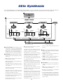
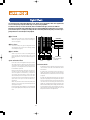
CS1x Synthesis
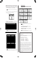
The secret behind the CS1x's exceptional quality sound is its ability to create rich and complex sonic textures in Performances, which are made up of
Layers of up to four AWM2 voices—either sounding simultaneously or mapped to various note and velocity zones across the keyboard.
AWM2 WAVEFORM
BANK
PROGRAM NUMBER
AWM2 VOICE
OSCILLATORS
FILTERS
AMPLIFIERS
EFFECTS
ATTACK LEVEL
( ATK LEVEL )
LEVEL
LEVEL
LEVEL
BASIC KEY
PLAYED
PITCH
INITIAL LEVEL
( INIT LEVEL )
TIME
ATTACK TIME
( ATK TIME )
KEY ON
DECAY TIME
( DCY TIME )
SUSTAIN LEVEL
( SUS LEVEL )
SUSTAIN LEVEL
(SUS LEVEL)
CUT OFF
FREQUENCY
TIME
RELEASE TIME RELEASE LEVEL
( REL TIME )
( REL LEVEL )
ATTACK TIME
( ATK TIME )
KEY OFF
KEY ON
DECAY TIME
( DCY TIME )
RELEASE TIME
( REL TIME )
KEY OFF
VOLUME
ATTACK TIME
( ATK TIME )
KEY ON
LFO
! AWM2 WAVEFORM - The fundamental source
of the CS1x's sound is the sampled AWM2
waveform. There are hundreds preprogrammed in
ROM which are used by the Performances.
Available waveforms are organized in Banks. Each
AWM2 waveform has its own Program Number.
" AWM2 VOICE - The AWM2 waveform combines
with the oscillator, filter and amplifier to make up
a CS1x voice.
• PEG - The Pitch Envelope Generator controls how
the pitch changes over time.
• FEG - The Filter Envelope Generator controls how
the timbre changes over time.
ATK TIME (Attack Time) determines the time
required for a sound to reach its maximum cutoff
frequency level when a note is played.
DCY TIME (Decay Time) determines the time
required for a sound to reach its Sustain Level from
the maximum level while the key is held.
SUS LEVEL (Sustain Level) sets the Sustain Level;
the cutoff frequency will be maintained at this level
for as long as the key is held.
REL TIME (Release Time) determines the time it
takes for the cutoff frequency to reach the level
preset for each voice after the key has been released.
ATK TIME (Attack Time) determines the time
required for a sound to reach its Attack Level after
a note is played.
• AEG - The Amplitude Envelope Generator controls
how the volume changes over time.
ATK LEVEL (Attack Level) sets the initially targeted
level after a note is played.
ATK TIME (Attack Time) determines the time
required for a sound to reach its maximum volume
level when a note is played.
REL TIME (Release Time) determines the time it
takes for the basic pitch to reach the Release Level
after the key has been released.
REL LEVEL (Release Level) sets the final targeted
level after the key is released.
RELEASE TIME
( REl TIME )
TIME
KEY OFF
CONTROLLER
INIT LEVEL (Initial Level) sets the initial pitch level
when a key is played.
DCY TIME (Decay Time) determines the time
required for a sound to reach its basic pitch from
the Attack Level while the key is held.
DECAY TIME
( DCY TIME )
DCY TIME (Decay Time) determines the time
required for a sound to reach its Sustain Level from
the maximum volume level while the key is held.
SUS LEVEL (Sustain Level) sets the Sustain Level;
the volume will be maintained at this level for as
long as the key is held.
REL TIME (Release Time) determines the time it
13
takes for a sound to sustain after the key has been
released.
# LFO - The Low Frequency Oscillator generates low
frequency signals which can be used to modulate
the PEG, FEG and AEG.
• PMOD - The LFO can apply Pitch Modulation to
the PEG to create vibrato effects.
• FMOD - The LFO can apply Filter Modulation to
the FEG to create wah-wah types of effects.
• AMOD - The LFO can apply Amplitude
Modulation to the AEG to create tremolo effects.
$ CONTROLLER - You can use several types of
controllers to manipulate various parameters in
realtime.
• MW - Use the Modulation Wheel to control
PMOD, FMOD, and Filter Cutoff.
• FC - Use the Foot Controller to control FMOD,
Filter Cutoff, and Variation Effect.
• Use the Sound Control Knobs to control AEG Attack
Time, Release Time, Filter Cutoff, and Resonance.
The ASSIGN 1/2 knobs can be specified to control
one of any number of parameters. (See the lists on
pages 27 and 29.)
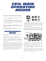
CS1x MAIN
OPERATING
MODES
The CS1x has two main operating modes: Performance mode and Multi
Play mode. The chief distinction between each mode is as follows:
AMP EG
VOLUME
• Performance mode is primarily for realtime performance of Layers. It
has six menus of Edit parameters.
ATTACK
RELEASE
ASSIGN 1/DATA
CUTOFF
RESONANCE
ASSIGN 2
2
MW/FC
1
FILTER
• Multi Play mode is primarily for multitimbral playback of up to 16
Parts when external MIDI devices are connected. It has one menu of
Edit parameters. You can also use the CS1x as a MIDI data input
device for an external sequencer.
SCENE
Turning the Sound Control Knobs will give you direct access to the AMP
EG and FILTER parameters, thus providing analog-style realtime control
over key characteristics of the sound. You can also save up to two
"snapshots" of knob positions in Scenes, which can be instantly recalled
at the touch of a SCENE button.
Utility mode lets you modify System and MIDI parameters which affect
both Performance and Multi Play mode. (For more information about
Utility mode, see page 40.)
Another way to edit a Performance is with the Edit Parameter Rotary
Switch and Parameter Value UP/DOWN buttons. These give you control
over both "Common" parameters which affect all Layer voices equally,
and "Layer" parameters which affect individual Layers, or AWM2 voices.
Store mode lets you store your own User Performances and Scenes. (For
more information about Store mode, see page 44.)
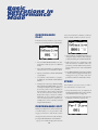
Performance
Mode
Edit Parameter Rotary Switch
If you're in a different mode, press the PERFORMANCE button to enter
Performance mode.
TYPE
ARPEGGIATOR
TEMPO
P BEND
RANGE
PMOD
SUB
DIVIDE
MW
FMOD
BANK
PROGRAM
CUTOFF
REV
TYPE
CHO
TYPE
FC
CUTOFF
EFECT
VARI
TYPE
LIMIT
LOW
LIMIT
HIGH
LIMIT
LOW
VARI
EF
VEL
LIMIT
OFFSET
HIGH
SUS
LEVEL
REL
TIME
AMOD
PMOD
FMOD
SUS
LEVEL
REL
TIME
INIT
LEVEL
ATK
LEVEL
VOLUME
PAN
REV
SEND
ATK
TIME
EFFECT
CHO
SEND
VEL
FIX
TRANS
CH
RCV
CH
TUNE
DETUNE
NOTE
SFT
AEG
DCY
ATK
TIME
TIME
FEG
DCY
ATK
TIME
TIME
In Performance Play mode you can select a Performance from 128 Preset
Performances and 128 User Performances and begin playing.
PERFORM
LEVEL
FMOD
NOTE
VARI
VARI
PARAM
DATA
PORTA
SWITCH
TIME
DEPTH
PERFORM
NAME
ASSIGN1
PARAM
COMMON
ASSIGN2
DATA
PARAM
LFO
WAVE
SPEED
PHASE
INIT
PEG
VARI
SEND
DCY
REL
TIME
TIME
FILTER
CUTOFF
REZ
LAYER
REL
LEVEL
POLY/
MONO
DEMO
A Performance is comprised of up to four "Layers", or AWM2 voices
sounding at once—either playing simultaneously across the length of the
keyboard, or playing independently according to specified key and
velocity ranges.
PERFORMANCE
MULTI
STORE
UTILITY
MASTER
TUNE
SYSTEM
VEL
KBD
CURVE
TRANS
MIDI
DEVICE
NO
LOCAL
BULK
DUMP
ASSIGN
CTRL
NO
UTILITY
Parameter Value UP/DOWN Buttons
In Performance mode there are six Edit menus of Common and Layer
parameters which can be accessed via the Edit Parameter Rotary Switch
and modified with the Parameter Value UP/DOWN buttons.
There are many Performance parameters which you can edit by offsetting
parameter values—i.e., adding to or subtracting from the values which
are preset for each voice. There are basically two ways to go about offsetting
the parameters—by turning the Sound Control Knobs, or using the Edit
Parameter Rotary Switch and Parameter Value UP/DOWN buttons.
Try changing the voice assignments to each Layer. This is a quick and
effective way to create an entirely new Performance, which you can
easily store as a User Performance.
Changing any parameter will automatically engage Performance Edit
mode. (You can easily switch back Performance Play mode by pressing
the PERFORMANCE button or PROGRAM [–]/[+] button.)
Assigning voices to the Layers is simple. Choose the Layer (1~4) with the
PART/LAYER [–]/[+] buttons, and select from a variety of AWM2
instrument voices and drum voices using the Bank and Program
Parameters (Layer Edit 4, sixth row from the top).
14
Basic
Basic
Operations
In
Operations
In
Performance
Performance
Mode
Mode
PERFORMANCE
PLAY
next to the Performance number, to indicate
that the edited sound has not been stored.
Performance Play mode lets you select a
Preset or User Performance for realtime play.
• Offset AMP EG and FILTER parameters to
change the shape and tone of the sound as
you play by turning the Sound Control Knobs.
• Press the PERFORMANCE button to enter
Performance mode (if you're in a different
mode).
• Press either the PRESET or USER button to
select the Preset or User Performance bank.
• Choose a Performance with the PROGRAM
[–]/[+] buttons.
• Use realtime control features as you play,
including the Pitch Bend and Modulation
Wheels.
• Transpose the octave up or down by holding
SHIFT and pressing PART/LAYER [–]/[+]. You
can transpose the pitch up ([+]) or down ([–])
by as many as three octaves, depending on
the Performance. (The transpose value will
also be reflected in the Utility mode's
Keyboard Transpose function. NOTE:
Maximum is ±3 octaves; however, when you
raise or lower the pitch in semitones, for
example, three octaves cannot be achieved
using the SHIFT button.)
PERFORMANCE EDIT
Making any adjustment—either intentionally
or inadvertently—to any parameter will
engage Performance Edit mode. When
exiting from the Performance Edit mode (by
pressing PERFORMANCE or PROGRAM
[–]/[+]), an "E" will be displayed in the LCD
15
• Replace the Layer voice assignment, or edit
other Performance Common and Layer
parameters, with the Edit Parameter Rotary
Switch and Parameter Value UP/DOWN
buttons.
• Press ARPEGGIATOR to turn it ON, and play
a chord to start the arpeggiated chords. Select
Arpeggiator Type, Tempo and other
parameters from the Common Edit 1 menu.
STORE
Store mode lets you store Scenes as well as
User Performances for later recall.
• Store your favorite Scenes, or "snapshots" of
Sound Control Knob positions, in the currently
selected Performance. (See page 44.)
• Store your own Performances in the 128 User
Performance memories. (See page 44.)
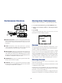
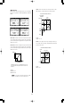
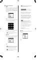
Performance Structure
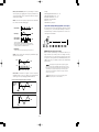
Storing User Performances
Storing your own User Performance is a quick and simple operation.
Preset Bank
User Bank
128 Performance
128 Performance
007
006
005
004
003
002
001
1. To store the current Performance, press the STORE button once.
007
006
005
004
003
002
001
2. Choose a User Performance number (1~128) using the numeric
keypad.
STORE IN USER BANK
3. Press ENTER.
001
Performance
COMMON EDIT
ARPEGGIATOR
TEMPO
TYPE
P BEND
RANGE
NOTE
SFT
SUB
DIVIDE
MW
FMOD
PMOD
PERFORM
LEVEL
CUTOFF
REV
TYPE
FMOD
CHO
TYPE
FC
CUTOFF
NOTE
TUNE
DETUNE
EFECT
VARI
TYPE
DCY
TIME
VARI
VARI
PARAM
DATA
PORTA
SWITCH
TIME
VARI
EF
VEL
OFFSET
LIMIT
LOW
LIMIT
HIGH
LIMIT
LOW
LIMIT
HIGH
SUS
LEVEL
REL
TIME
AMOD
PMOD
FMOD
ATK
TIME
EFFECT
CHO
SEND
ATK
LEVEL
AEG
ATK
TIME
DEPTH
Layer 4
Layer 3
VOICE
Layer 2
VOICE
Layer 1
PERFORM
NAME
ASSIGN1
PARAM
A "Sure?" prompt will appear in the LCD. Press YES to store the
Performance. Press NO to abort the operation.
VOICE
VOICE
COMMON
ASSIGN2
DATA
PARAM
LFO
FEG
WAVE
SPEED
PHASE
INIT
PEG
ATK
TIME
DCY
TIME
SUS
LEVEL
REL
TIME
INIT
LEVEL
BANK
PROGRAM
VOLUME
PAN
REV
SEND
VARI
SEND
DCY
REL
TIME
TIME
FILTER
CUTOFF
REZ
LAYER
REL
LEVEL
POLY/
MONO
AMP EG
ATTACK
RELEASE
ASSIGN 1/DATA
CUTOFF
RESONANCE
ASSIGN 2
DEMO
PERFORMANCE
MULTI
STORE
UTILITY
LAYER EDIT
MASTER
TUNE
SYSTEM
VEL
KBD
TRANS
CURVE
VEL
FIX
TRANS
CH
RCV
CH
MIDI
DEVICE
NO
LOCAL
2
MW/FC
BULK
DUMP
ASSIGN
CTRL
NO
UTILITY
1
FILTER
SCENE
SAVE AS SCENE 1 or 2
REAL TIME EDIT with
THE SOUND CONTROL KNOBS
! PERFORMANCE BANKS - The CS1x comes preprogrammed with
128 Preset Performances and 128 User Performances. You can edit
the Layers of the currently selected Performance and store it in a User
Performance.
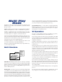
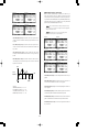
Scenes
" LAYERS - A Performance consists of up to four Layers—each Layer
can be assigned its own AWM2 voice. There are many Layer and
Common Performance parameters which can be edited.
There are two "Scene" memories dedicated to each Performance. Scenes
are simply "snapshots" of specific positions of the Sound Control Knobs—
instantly accessible via the SCENE buttons.
# AMP EG/FILTER - Turning the Sound Control Knobs will affect all
Layers equally by offsetting AMP EG parameters to control the shape
of the volume of the sound over time, and FILTER parameters to control
the quality of the tone. In Edit mode you can assign which parameters
the ASSIGN 1 and ASSIGN 2 knobs will control.
You can select one of the Scenes by pressing the SCENE 1 or SCENE
2 button. Or you can hold one SCENE button and press the other,
then use the Modulation Wheel or Foot Controller for realtime
continuous parameter changes between one Scene and the other.
The default controller is Modulation Wheel. The minimum position
of the controller is Scene1, and the maximum position is Scene 2.
$ COMMON EDIT 1~2 - These are "Common" parameters which affect
all Layers in the Performance equally.
Storing Scenes
You can easily store your own Scenes in a Performance—either
temporarily or permanently.
% LAYER EDIT 1~4 - These are "Layer" parameters which let you modify
the characteristics of each individual Layer. Select the Layer you want
to edit using the PART/LAYER [–]/[+] buttons.
To store a Scene temporarily in the currently selected Performance, hold
a SCENE button and press STORE.
This will store the Scene in the edit buffer as long as the current Performance
is selected, so that the original Scenes are protected. If you select another
Performance, any new Scenes will be lost.
To store a Scene permanently in a Performance, simply perform the Store
operation for User Performances. (See Storing User Performances, above.)
16
Multi Play
Mode
insert voice Program Change messages at the head of your sequences,
however, the right Part voices will always be selected automatically when
you start your sequencer from the beginning of the song.)
In Multi Play mode you can select a voice from the GM bank of 128
AWM2 voices (accessible via the PROGRAM [–]/[+] buttons) and start
playing in realtime.
MULTITIMBRAL PLAY - As a GM- and XG-compatible multitimbral
MIDI tone generator, the CS1x can receive note and other data on each
of the 16 MIDI channels, sent from an external sequencer or computer,
thus playing the corresponding 16 Parts.
Multi Play mode lets you use the CS1x as a master keyboard controller or
MIDI note data input device, as well as a multitimbral tone generator.
A Multi is a configuration of up to 16 instrument "Parts" (each Part is
assigned to a MIDI channel) which can be played simultaneously when
an external sequencer or computer is connected to the CS1x.
XG Operation
The CS1x is a fully equipped, stand-alone XG-MIDI tone generator,
featuring a total of 480 normal voices and 11 drum voices.
Choose the Part with the PART/LAYER [–]/[+] buttons, and assign a voice
to it by selecting from the 480 GM- and XG-compatible AWM2 normal
(instrument) voices and 11 drum voices (kits), using the Edit menu Bank
and Program Parameter Value UP/DOWN button.
The XG format maintains the universality and compatibility of the MIDI
and General MIDI System Level 1 standards, while significantly increasing
the range of expressiveness through much greater control over voice
modifications and effects.
In Multi Play mode there is one menu of Edit parameters which can be
accessed via the Parameter Value UP/DOWN button.
In addition to supporting the 128 GM voices, the XG format provides for
Bank Select messages that significantly expand the number of voices
available for use.
Turning the Sound Control Knobs will affect only a single AWM2 voice,
i.e., the currently selected Part.
Many of the new XG voices are variations of basic GM voices which are
stored in additional banks. Each bank is associated with a specific type of
variation, so that voices are easy to locate. When using an external
sequencer to control the CS1x, additional banks are selected by the
appropriate Bank-Select LSB values.
Multi Structure
Part 1~16
7
6
5
4
3
BANK
PROGRAM
VOLUME
PAN
EFFECT
FILTER
POLY/MONO
The XG format also supports a full SFX bank of extension effects, which
are selected by a Bank-Select MSB value of 40H. Bank-Select MSB 7H,
in contrast, can be used to set any channel to rhythm-part play.
The XG format allows creation of extremely expressive control data which
can change a voice's Harmonic Contents, Brightness, and many more
critical Control Change and other parameters.
2
1
PART SELECT
The XG format also offers high level effects support, enabling control of
effects types, circuit operation, plus internal parameter settings for both
basic and elaborate effects. This means you can freely control the
parameters of the CS1x's 11 Reverb, 11 Chorus and 43 Variation types of
effects independently.
PART SELECT - In Multi Play mode each "Part" is made up of an AWM2
voice. You can select and play any of the 16 Parts by pressing the PART/
LAYER [–]/[+] buttons. Since the notes you play on the keyboard and the
buttons you press on the panel are sending MIDI messages, the CS1x is
ideal as a MIDI input device.
(For more information about MIDI related parameters, see the Appendix,
page 53.)
The CS1x also features another play mode —TG300B mode— which
lets you play back commercially available MIDI files in this format.
EDITING PARTS - Select the Part you want to edit using the PART/LAYER
[–]/[+] buttons. Each of the Multi parameters are printed above the
Parameter Value UP/DOWN button. To set up your own 16 Parts, assign
a voice to the Part using the Bank and Program parameters accessible by
the first two Parameter Value UP/DOWN buttons. (Note that these settings
will not be retained when the power is turned off, since the XG default
parameters are always reinstated when the power is turned on. If you
17
18
Following is a description of each function in the various modes.
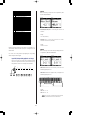
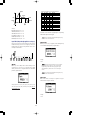
In Performance mode you can choose from 128 Preset and 128 User Performances. A Performance consists of a
maximum of four layered sounds (voices). The Performance Edit function lets you easily edit each Layer within a
Performance. The various parameters give you the flexibility to create a vast variety of sounds.
Entering Performance Mode
● Selecting a Performance
Press the PERFORMANCE button. A [▲] mark will appear in the
LCD below the word "PERFORMANCE".
1. Use the numeric keypad (0 ~ 9) to select the Performance
number you want.
PERFORMANCE
MULTI
STORE
UTILITY
DEMO
ERFORMANCE
MULTI
STORE
UTILITY
*&
VWX
YZ'
7
8
9
MNO
PQR
STU
4
5
6
DEF
GHI
JKL
1
2
3
ABC
PRESET USER ARPEGGIATOR
SPACE
0
ENTER
NO/
QUICK PC
Performance Play Mode
YES
NOTE For more information about each Performance, see the
Performance List in the "Data List" book.
● Selecting a Bank
2. Press the ENTER button to confirm the Performance number
(1~128). The Performance name and number you have
selected will display in the LCD. The Category name will be
shown next to the Performance name.
There are 2 banks, a Preset bank and a User bank. Each bank
contains 128 Performances.
Preset Bank
128 Performance
007
006
005
004
003
002
001
User Bank
128 Performance
Category
007
006
005
004
003
002
001
Performance Name
VWX
Press the PRESET button or the USER button to select the bank you want.
A [▼] mark will appear in the LCD above the word "PRESET" or "USER".
RPEGGIO HOLD
*&
7
8
9
MNO
PQR
STU
4
5
6
DEF
GHI
JKL
1
2
3
ABC
SPACE
0
ENTER
NO/
QUICK PC
YES
Performance Number
Press the PROGRAM [+] button to select the next Performance
number. Press the PROGRAM [-] button to select the previous
Performance number.
SHIFT
+
PART/LAYER/ OCTAVE
PRESET
YZ'
USER
+
PROGRAM
ARPEGGIO HOLD
SHIFT
+
PART/LAYER/ OCTAVE
RPEGGIO HOLD
SHIFT
PRESET
USER
+
+
PART/LAYER/ OCTAVE
PRESET
PROGRAM
USER
+
PROGRAM
20
● Edit Procedure
Quick Program Change
Press the QUICK PC (Quick Program Change) button in the numeric
keypad to fix all the numbers except the first digit of the Performance
number in the LCD. By pressing a button in the numeric keypad
(0~9), you can quickly select the Performance numbers within a
group of ten by changing the first digit of the Performance number.
The hundredth and tenth digits will be shown as bold characters to
indicate they are fixed. This lets you quickly switch between ten types
of Performances during a live performance. To cancel the function,
press the QUICK PC button again.
1. Select the Edit function.
Turn the Edit Parameter Rotary switch to choose the Common or Layer
Edit menu with the parameter you want to edit.
TYPE
ARPEGGIATOR
TEMPO
P BEND
RANGE
PMOD
NOTE
SFT
SUB
DIVIDE
MW
FMOD
TUNE
DETUNE
PERFORM
LEVEL
FMOD
CHO
TYPE
FC
CUTOFF
REV
TYPE
CUTOFF
NOTE
LIMIT
LOW
LIMIT
HIGH
LIMIT
LOW
LIMIT
HIGH
EFECT
VARI
TYPE
VEL
OFFSET
8
9
MNO
PQR
STU
4
5
6
DEF
GHI
JKL
1
2
ASSIGN1
PARAM
COMMON
ASSIGN2
DATA
PARAM
LFO
DCY
TIME
SUS
LEVEL
REL
TIME
AMOD
PMOD
FMOD
ATK
TIME
DCY
TIME
SUS
LEVEL
REL
TIME
INIT
LEVEL
ATK
LEVEL
BANK
PROGRAM
VOLUME
PAN
REV
SEND
ATK
TIME
EFFECT
CHO
SEND
VEL
FIX
TRANS
CH
RCV
CH
WAVE
PHASE
INIT
SPEED
PEG
*&
YZ'
7
DEPTH
AEG
ATK
TIME
FEG
VWX
PERFORM
NAME
VARI
VARI
DATA
PARAM
PORTA
TIME
SWITCH
VARI
EF
VARI
SEND
LAYER
REL
LEVEL
POLY/
MONO
DCY
REL
TIME
TIME
FILTER
CUTOFF
REZ
DEMO
PERFORMANCE
MULTI
STORE
UTILITY
MASTER
TUNE
SYSTEM
VEL
KBD
CURVE
TRANS
MIDI
DEVICE
NO
LOCAL
ASSIGN
CTRL
NO
BULK
DUMP
UTILITY
3
ABC
SPACE
0
ENTER
NO/
QUICK PC
2. Select a Layer (if you want to change the Layer parameters).
YES
Use the LAYER [-]/[+] buttons to select the Layer you want to edit.
NOTE You can also use the Quick Program Change function when
selecting the program number for each Part in Multi Play mode (page 36).
ARPEGGIO HOLD
SHIFT
+
PART/LAYER/ OCTAVE
Performance Edit Mode
PRESET
USER
+
PROGRAM
You can edit any Preset or User Performance to create your
own unique Performance by changing the various
parameters, including the voice assignment to each Layer.
You can then store the Performance you have edited in a User
Performance number (1~128).
NOTE You do not need to select a Layer if you are editing the
Common parameters, since these are applied equally to all Layers in
a Performance.
3. Select a parameter.
Press the Parameter Value UP/DOWN button corresponding to the
parameter you want to edit once to select the parameter. The current
settings will display in the LCD.
NOTE
Changing any parameter in a Performance will
automatically engage Performance Edit mode.
Preset Bank
User Bank
128 Performance
128 Performance
007
006
005
004
003
002
001
007
006
005
004
003
002
001
TYPE
ARPEGGIATOR
TEMPO
P BEND
RANGE
PMOD
NOTE
SFT
PERFORM
LEVEL
SUB
DIVIDE
MW
FMOD
TUNE
DETUNE
CUTOFF
REV
TYPE
FMOD
CHO
TYPE
FC
CUTOFF
NOTE
EFECT
VARI
TYPE
VA
PAR
SW
VARI
EF
VEL
OFFSET
LIMIT
LOW
LIMIT
HIGH
LIMIT
LOW
LIMIT
HIGH
DCY
LEVEL
REL
TIME
AMOD
PMOD
FMOD
ATK
LEVEL
D
T
VARI
SEND
CU
DE
AEG
LFO
ATK
TIME
DCY
TIME
ATK
TIME
DCY
TIME
DCY
LEVEL
REL
TIME
INIT
LEVEL
BANK
PROGRAM
VOLUME
PAN
REV
SEND
ATK
TIME
EFFECT
CHO
SEND
VEL
FIX
TRANS
CH
RCV
CH
FEG
Store into a Performance
001
Performance
Layer 4
Layer 3
VOICE
Layer 2
VOICE
Layer 1
TYPE
P BEND
RANGE
PMOD
SUB
DIVIDE
MW
FMOD
TUNE
DETUNE
PERFORM
LEVEL
CUTOFF
REV
TYPE
FMOD
EFECT
VARI
TYPE
CHO
TYPE
FC
CUTOFF
NOTE
LIMIT
HIGH
VEL
OFFSET
LIMIT
LOW
LIMIT
HIGH
LIMIT
LOW
SUS
LEVEL
REL
TIME
AMOD
PMOD
FMOD
ATK
TIME
DCY
TIME
SUS
LEVEL
REL
TIME
INIT
LEVEL
PROGRAM
VOLUME
PAN
REV
SEND
ATK
TIME
EFFECT
CHO
SEND
ATK
LEVEL
BANK
NOTE
SFT
VARI
VARI
PARAM
DATA
PORTA
SWITCH
TIME
VARI
EF
DEPTH
AEG
ATK
TIME
DCY
TIME
WAVE
ASSIGN2
PARAM
DATA
SPEED
PHASE
INIT
PEG
VARI
SEND
DCY
REL
TIME
TIME
FILTER
CUTOFF
REZ
PERFORMANCE
MULTI
STORE
UTILITY
COMMON
LFO
FEG
SYSTEM
VEL
KBD
CURVE
TRANS
LAYER
REL
LEVEL
POLY/
MONO
MASTER
TUNE
AMP EG
ATTACK
RELEASE
ASSIGN 1/DATA
CUTOFF
RESONANCE
ASSIGN 2
MIDI
DEVICE
NO
LO
LAYER EDIT
DEMO
PERFORMANCE
PERFORM
NAME
ASSIGN1
PARAM
DEMO
VOICE
VOICE
COMMON EDIT
ARPEGGIATOR
TEMPO
W
PEG
MULTI
2
STORE
MW/FC
UTILITY
MASTER
TUNE
SYSTEM
KBD
VEL
CURVE
TRANS
VEL
FIX
TRANS
CH
RCV
CH
MIDI
DEVICE
NO
LOCAL
BULK
DUMP
ASSIGN
CTRL
NO
UTILITY
1
FILTER
SCENE
4. Set the value.
Realtime edit with Sound Control Knobs
Select SCENE 1/2
Press the Parameter Value UP/DOWN button again to set the value.
Holding the Parameter Value UP/DOWN button changes the value
continuously. The [UP] button increases the value and the [DOWN]
button decreases the value.
NOTE Edit parameters are basically divided into two groups:
Common parameters equally applied to all the Layers in a
Performance, and Layer parameters independently set for each Layer
in a Performance.
TYPE
ARPEGGIATOR
TEMPO
P BEND
RANGE
PMOD
NOTE
SFT
SUB
DIVIDE
MW
FMOD
TUNE
DETUNE
PERFORM
LEVEL
CUTOFF
REV
TYPE
FMOD
CHO
TYPE
FC
CUTOFF
NOTE
EFECT
VARI
TYPE
P
S
VARI
EF
VEL
OFFSET
LIMIT
LOW
LIMIT
HIGH
LIMIT
LOW
LIMIT
HIGH
DCY
LEVEL
REL
TIME
AMOD
PMOD
FMOD
ATK
LEVEL
D
AEG
LFO
ATK
TIME
DCY
TIME
ATK
TIME
DCY
TIME
DCY
LEVEL
REL
TIME
INIT
LEVEL
BANK
PROGRAM
VOLUME
PAN
REV
SEND
ATK
TIME
EFFECT
CHO
SEND
VEL
FIX
TRANS
CH
RCV
CH
FEG
PEG
VARI
SEND
DEMO
PERFORMANCE
MULTI
STORE
UTILITY
MASTER
TUNE
21
SYSTEM
VEL
KBD
CURVE
TRANS
MIDI
DEVICE
NO
C
NOTE You can also use the numeric keypad (0~9) or the Data
Entry knob to change the value.
NOTE To exit Performance Edit mode, press the PERFORMANCE
button again or the PROGRAM [-]/[+] button. You can enter Multi Play
mode directly from Performance mode by pressing the MULTI button.
NOTE To change the value for all four Layers at one time, hold
SHIFT and press the Parameter Value UP/DOWN button. When you
press SHIFT in Performance Edit mode, a letter "A" (All) will appear in
the LCD below the word "LAYER".
TYPE
ARPEGGIATOR
TEMPO
P BEND
RANGE
PMOD
Edit Mark
Once you have edited a Performance in any way, an edit mark (a
reversed type letter "E") will appear to the left of the Performance
number. This mark indicates you have edited, but not stored the
Performance.
D
NOTE
SFT
ARPEGGIO HOLD
L
AEG
SHIFT
+
ATK
TIME
DCY
TIME
ATK
TIME
DCY
TIME
L
BANK
PROGRAM
VO
L
FEG
PART/LAYER/ OCTAVE
PRESET
F
TUNE
DETUNE
USER
+
PROGRAM
DEMO
PERFORMANCE
MULTI
STORE
UTILITY
Indicates you have edited,
but not stored the Performance.
MASTER
TUNE
SYSTEM
KBD
C
TRANS
NOTE The edit mark will also appear simply by making a slight
position change to a Sound Control Knob (see page 6).
● Description of Each Function
Common Edit 1 (applied to all Layers)
This row provides functions and parameters which are common
to all Layers in a Performance, such as the Arpeggiator, and the
Performance Level, Effect and Name.
NOTE Each voice is preset with optimum settings for the parameters,
and the value you set for any parameter will offset (add or subtract) the
preset value. If the value of a parameter exceeds the maximum or
minimum limit available, the highest or lowest value will be used.
TYPE
ARPEGGIATOR
TEMPO
P BEND
RANGE
PMOD
NOTE
SFT
NOTE The actual value is the sum of the value displayed in the
LCD and the value set by the Sound Control Knob.
SUB
DIVIDE
MW
FMOD
TUNE
DETUNE
PERFORM
LEVEL
CUTOFF
FMOD
REV
TYPE
CHO
TYPE
FC
CUTOFF
NOTE
LIMIT
LOW
LIMIT
HIGH
LIMIT
LOW
LIMIT
HIGH
EFECT
VARI
TYPE
VEL
OFFSET
DEPTH
PERFORM
NAME
ASSIGN1
PARAM
COMMON
ASSIGN2
PARAM
DATA
LFO
AEG
ATK
TIME
DCY
TIME
DCY
LEVEL
REL
TIME
AMOD
PMOD
FMOD
ATK
TIME
DCY
TIME
DCY
LEVEL
REL
TIME
INIT
LEVEL
ATK
LEVEL
BANK
PROGRAM
VOLUME
PAN
REV
SEND
ATK
TIME
EFFECT
CHO
SEND
WAVE
SPEED
PHASE
INIT
PEG
FEG
NOTE
VARI
VARI
DATA
PARAM
PORTA
TIME
SWITCH
VARI
EF
VARI
SEND
DCY
REL
TIME
TIME
FILTER
CUTOFF
REZ
LAYER
REL
LEVEL
POLY/
MONO
DEMO
The original voice can be restored and heard by returning
to Performance Play mode and moving the Sound Control Knob to the
center position.
PERFORMANCE
MULTI
STORE
UTILITY
SYSTEM
MIDI
ASSIGN
■ ARPEGGIATOR
NOTE You can replace the voices currently assigned to each Layer
with new voices or assign a voice to an empty Layer (up to four
voices/Layers for a Performance).
The Arpeggiator automatically creates arpeggiated chords
based on the chords/melodies you play on the keyboard. There
are three Arpeggiator parameters: TYPE, TEMPO and SUBDIVIDE.
5. Set the other parameters.
As you continue pressing the other Parameter Value UP/DOWN
buttons, the other parameters will appear in the display. Set the other
parameters to your preference.
TYPE
6. Store the Performance.
When you have finished editing, store the Performance as a User
Performance. For details about how to store a Performance, see page 44.
SUBDIVIDE
NOTE
The edited contents will be retained in memory even if you
turn the power off during an edit. The Performance you were editing
will still be selected the next time you turn the power on, and you will
be able to pick up from where you left off and continue editing the
Performance.
While editing a Performance, if you select another
Performance or press the PERFORMANCE button again to exit
Performance Edit mode before you have first stored the data as a
User Performance, your edited data will be lost. For details about
storing a User Performance, see page 44.
22
TEMPO
■ PERFORM LEVEL
To start the Arpeggiator, press the ARPEGGIATOR button to turn it
on. A [▼ ] mark will appear in the LCD above the word
"ARPEGGIATOR".
NOTE
This sets the volume of each Performance.
To turn the Arpeggiator off, press the ARPEGGIATOR button
again.
TYPE: Sets the type of arpeggio. You can choose from 30 types.
For details about each type, see the Arpeggiator Type List in the
"Data List" book.
Settings:
PERFORM LEVEL (Performance Level): 0~127
Arpeggiator Hold
The Arpeggiator Hold function lets you play a chord to start the
automatic arpeggio, then take your hand off the keyboard; the
arpeggiated chord will play continuously in a loop. Play another
chord and the automatic arpeggios will change accordingly.
■ EFFECT
There are five effect parameters: REV TYPE (Reverb Type), CHO
TYPE (Chorus Type), VARI TYPE (Variation Type), VARI PARAM
(Variation Parameter) and VARI DATA (Variation Data).
For more basic information on each effect, see page 47.
To activate the Arpeggiator Hold function, perform the following:
1. Hold SHIFT and press ARPEGGIATOR. The Arpeggiator indicator in
the LCD will start blinking.
2.Play a series of chords.
Reverb Type
Chorus Type
Variation Type
Variation Parameter
3.To stop the arpeggiated chords, press ARPEGGIATOR again.
Arpeggiator Split
If you hold SHIFT and press the Parameter Value [UP] button when
the TYPE parameter is displayed in the LCD, the Arpeggiator Split
function will be enabled, and a reversed type letter "S" will appear
to the right of the Arpeggiator type.
The Split function splits the keyboard from C3 (indicated above the
keyboard with [▼]) and will allow you to play the arpeggiated chords
on the lower half (below C3) of the keyboard, and play a melody line on
the upper half (C3 and above).
To cancel the Split function, hold SHIFT and press the Parameter
Value [DOWN] button.
Variation Data
TEMPO: Sets the tempo of the Arpeggiator. The range is MIDI, 40
~ 240.
The letter "P" (Parameter) or "d"
(Data) displays to distinguish
between the Variation Parameter
and Variation Data screens.
Settings:
TEMPO: MIDI, 40 ~ 240 (beats per minute)
NOTE If you want to synchronize the tempo of the Arpeggiator
with that of an external MIDI device, set the TEMPO parameter to MIDI.
REV TYPE (Reverb Type): Sets the Reverb type. You can choose
from 11 types. For more information about each Reverb type, see
Effect Type List on page 49.
SUBDIVIDE: Determines the basic note settings (how fine the
tempo is divided) of the Arpeggiator.
Settings:
SUBDIVIDE: 3/8=
1/12=
, 1/16=
NOTE
, 1/4= , 3/16= , 1/6=
, 1/24=
, 1/32=
, 1/8=
, 3/32=
CHO TYPE (Chorus Type): Sets the Chorus type. You can choose
from 11 types. For more information about each Chorus type, see
Effect Type List on page 49.
,
VARI TYPE (Variation Type): Sets the Variation effect type. There are
43 types to choose from. For more information about each Variation
effect type, see Effect Type List on page 49.
The Arpeggiator data cannot be output as the MIDI messages.
VARI PARAM (Variation Parameter): Selects the Variation effect
parameters. Parameters will differ depending on the Variation
effect type selected in VARI TYPE.
23
■ PERFORM NAME (Performance Name)
NOTE If you select EFFECT OFF in the Variation Type menu, the
layers which have the VARI SEND function set to ON will not sound.
When you don't want to use the Variation Effect on the layers, set VARI
TYPE to Thru.
This lets you select the Category and name the User Performances
using up to eight letters, numbers, symbols and characters.
1. Use the Parameter Value UP/DOWN button to move the
cursor to the position at which you want to enter a
character.
NOTE
Variation effect works as an Insertion effect in Performance
mode. For more information, see page 47.
For more information about each Variation effect parameter, see
Effect Parameter List on page 49.
2. Move the cursor left-most if necessary (the word
"Category" will appear instead of the Performance
name) and use the numeric keypad (0~9) to select the
Category.
VARI DATA (Variation Data): Sets the data (value) of the
Variation effect parameter selected in VARI PARAM. For more
information about each Variation effect data, see the Effect Data
Assign Table on page 51.
#
0
1
2
3
4
5
6
7
8
9
10
11
12
13
14
15
16
17
18
19
20
21
22
NOTE When VARI TYPE is turned off, VARI PARAM and VARI DATA
will be disabled.
NOTE The effect depth and other parameters can be controlled
using the ASSIGN 1 Sound Control Knob or a Foot Controller. For
details, see page 26.
NOTE
For more information, see page 47.
LCD
-Pf
Cp
Or
Gt
Ba
St
En
Br
Rd
Pi
Ld
Pd
Fx
Et
Pc
Se
Dr
Sc
Vo
Co
Wv
Sq
Category Name
Not specified
Piano
Chromatic Percussion
Organ
Guitar
Bass
Strings/Orchestral
Ensemble
Brass
Reed
Pipe
Synth Lead
Synth Pad
Synth SFX
Ethnic
Percussive
Sound Effect
Drums
Synth Comping
Vocal
Combination
Material Wave
Sequence
3. Move the cursor one position to the right (the current
cursor position will start blinking) and use the numeric
keypad (0~9) to select the first letter, then right one
position more and select the second letter, etc., until you
complete your Performance name.
TYPE
ARPEGGIATOR
TEMPO
P BEND
RANGE
PMOD
SUB
DIVIDE
MW
FMOD
PERFORM
LEVEL
CUTOFF
TUNE
NOTE
LIMIT
NOTE
DETUNE
LOW
SFT
AEG
SUS
ATK
DCY
LEVEL
TIME
TIME
FEG
SUS
ATK
DCY
LEVEL
TIME
TIME
BANK
PROGRAM
VOLUME
REV
TYPE
FMOD
CHO
TYPE
FC
CUTOFF
EFECT
VARI
TYPE
VARI
VARI
DATA
PARAM
PORTA
TIME
SWITCH
VARI
EF
LIMIT
HIGH
LIMIT
LOW
VEL
LIMIT
OFFSET
HIGH
REL
TIME
AMOD
PMOD
DEPTH
PERFORM
NAME
ASSIGN1
PARAM
COMMON
ASSIGN2
DATA
PARAM
LFO
FMOD
WAVE
SPEED
PHASE
INIT
PEG
REL
TIME
INIT
LEVEL
PAN
REV
SEND
ATK
TIME
EFFECT
CHO
SEND
VEL
FIX
TRANS
CH
RCV
CH
ATK
LEVEL
VARI
SEND
DCY
REL
TIME
TIME
FILTER
CUTOFF
REZ
LAYER
REL
LEVEL
POLY/
MONO
DEMO
PERFORMANCE
MULTI
STORE
UTILITY
MASTER
TUNE
SYSTEM
VEL
KBD
CURVE
TRANS
MIDI
DEVICE
NO
LOCAL
BULK
DUMP
ASSIGN
CTRL
NO
UTILITY
Settings:
ABCDEFGHIJKLMNOPQRSTUVWXYZ'abcdefg
hijklmnopqrstuvwxyz0123456789-/.,*&_
(space)
24
Common Edit 2 (applied to all Layers)
■ MW (Modulation Wheel)
This row provides functions and parameters which are common
to all Layers in a Performance (except for "Portament"), including
the settings for realtime controllers such as the Pitch Wheel,
Modulation Wheel and Foot Controller.
This sets the control parameters of the Modulation Wheel. There
are three parameters: PMOD (Pitch Modulation), FMOD (Filter
Modulation) and CUTOFF (Cutoff). The parameters set here can
be controlled with the Modulation Wheel to add vibrato or
tremolo effects to the sound.
TYPE
ARPEGGIATOR
TEMPO
P BEND
RANGE
PMOD
SUB
DIVIDE
MW
FMOD
TUNE
NOTE
DETUNE
SFT
AEG
ATK
DCY
TIME
TIME
FEG
ATK
DCY
TIME
TIME
BANK
PROGRAM
PERFORM
LEVEL
CUTOFF
REV
TYPE
FMOD
NOTE
CHO
TYPE
FC
CUTOFF
EFECT
VARI
TYPE
VARI
VARI
PARAM
DATA
PORTA
SWITCH
TIME
VARI
EF
LIMIT
LOW
LIMIT
HIGH
LIMIT
LOW
VEL
LIMIT
OFFSET
HIGH
DCY
LEVEL
REL
TIME
AMOD
PMOD
FMOD
DCY
LEVEL
REL
TIME
INIT
LEVEL
PAN
REV
SEND
ATK
TIME
EFFECT
CHO
SEND
ATK
LEVEL
VOLUME
DEPTH
PERFORM
NAME
ASSIGN1
PARAM
COMMON
Pitch Modulation
ASSIGN2
DATA
PARAM
Filter Modulation
LFO
WAVE
SPEED
PHASE
INIT
PEG
VARI
SEND
DCY
REL
TIME
TIME
FILTER
CUTOFF
REZ
LAYER
REL
LEVEL
POLY/
MONO
DEMO
PERFORMANCE
MULTI
STORE
UTILITY
■ P BEND RANGE (Pitch Bend Range)
Cutoff
This sets the Pitch Bend range in semitones. The pitch can be
bent up or down within the range set here by moving the Pitch
Wheel.
PMOD (Pitch Modulation): Sets the pitch modulation depth
created by the LFO (Low Frequency Oscillator). The value set here
will determine the range of the pitch modulation by the
Modulation Wheel. Moving the Modulation Wheel up will
increase the depth of the pitch modulation, while moving it
down will decrease the depth.
Settings:
-24 ~ +24 semitones
FMOD (Filter Modulation): Sets the filter modulation depth
created by the LFO (Low Frequency Oscillator). The value set here
will determine the range of the filter modulation by the
Modulation Wheel. Moving the Modulation Wheel up will
increase the depth of the filter modulation, while moving it down
will decrease the depth.
CUTOFF (Cutoff): Sets the range of the cutoff frequency points
above which the other frequencies are cut off. The value set here
will determine the range of the cutoff frequency points when
using the Modulation Wheel. Moving the Modulation Wheel up
will raise the cutoff frequency point (i.e., make the voice
brighter), while moving it down will lower the cutoff point (i.e.,
make the voice darker).
Settings:
PMOD (Pitch Modulation): 0~127
FMOD (Filter Modulation): 0~127
CUTOFF: -64 ~ +63
25
■ FC (Foot Control)
■ PORTA (Portamento)
This sets the parameters controlled by a Foot Controller
connected to the FOOT CONTROLLER jack on the rear panel.
There are three parameters: FMOD (Filter Modulation), CUTOFF,
and VARI EF (Variation Effect).
This sets the Portamento function. Portamento continuously
changes the pitch from one note to the next, thus letting you
glide the pitch from one note to the next. There are two
parameters, SWITCH and TIME. Values can be set for each Layer.
Filter Modulation
Switch
Cutoff
Time
Variation Effect
SWITCH: Turns the Portamento on or off. (for each layer)
TIME: Sets the time it takes for the pitch to reach the next note
played. (for all layers)
Settings:
SWITCH: on, off
TIME: 0~127
FMOD (Filter Modulation): Sets the filter modulation depth
created by the LFO (Low Frequency Oscillator). The value set here
will determine the range of the filter modulation by the Foot
Controller. Pressing the Foot Controller will increase the depth of
the filter modulation.
■ ASSIGN1 PARAM (ASSIGN 1 Parameter)
This determines which parameter will be controlled by the
ASSIGN 1 Sound Control Knob. You can choose from 28 types of
parameters.
CUTOFF: Sets the range of the cutoff frequency points above
which other frequencies are cut off. The value set here will
determine the range of the cutoff frequency points by the Foot
Controller. Pressing the Foot Controller will raise the cutoff
frequency point (i.e., make the voice brighter).
The parameter assigned to the ASSIGN1 knob as the default
differs depending on the Performance selected.
VARI EF (Variation Effect): Determines the Variation effect range
set by the EFFECT parameters (page 23), controlled by the Foot
Controller.
NOTE For details about which parameters the Foot Controller can
control, see the Effect Parameter List on page 49.
Settings:
For details about each parameter, see the reference pages as
listed on the next page.
Settings:
FMOD (Filter Modulation): 0~127
CUTOFF: -64 ~ +63
VARI EF (Variation Effect): -64 ~ +63
26
#
0
1
2
3
4
5
6
7
8
9
10
11
12
13
14
15
16
17
18
19
20
21
22
23
24
25
26
27
28
29
■ TUNE
LCD
off
PerfLevel (Performance Level) (page 23)
ArpgTempo (Arpeggiator Tempo) (page 23)
ArpgType (Arpeggiator Type) (page 23)
ArpgSubdiv (Arpeggiator Subdivide) (page 23)
MWCutoff (MW Cutoff) (page 25)
MWPModDpth (MW Pitch Modulation Depth) (page 25)
MWFModDpth (MW Filter Modulation Depth) (page 25)
PBRange (Pitch Bend Range) (page 25)
FCCutoff (FC Cutoff) (page 26)
FCFModDpth (FC Filter Modulation Depth) (page 26)
FCVariDpth (FC Variation Depth) (page 26)
PortaTime (Portamento Time) (page 26)
*FEGDcyTime (FEG Decay Time) (page 32)
*AEGDcyTime (AEG Decay Time) (page 30)
*ChoToRev (Chorus Send To Reverb)
*VariCntrl (Variation Control)
*RevChoSend (Reverb And Chorus Send)
*ChorusSend (Chorus Send) (page 38)
*ReverbSend (Reverb Send) (page 38)
*Pan (page 38)
*LFOSpeed (LFO Speed) (page 31)
*LFOPMod (Vibrato Depth) (page 30)
*VibDelay (Vibrato Delay)
*LFOAMod (LFO Amplitude Modulation Depth) (page 30)
*LFOFMod (LFO Filter Modulation Depth) (page 31)
*FEGAtkTime (FEG Attack Time) (page 32)
*FEGSusLvl (FEG Sustain Level) (page 32)
*FEGVelSens (FEG Level Velocity Sensitivity)
*Pitch (Oscillator Pitch)
This sets the tuning of a Layer. There are two parameters, NOTE
SFT (Note Shift) and DETUNE.
Note Shift
Detune
NOTE SFT (Note Shift): Raises or lowers the pitch of the voice in
semitones.
Settings:
-24 ~ +24 (semitones)
DETUNE: Raises or lowers the pitch of the voice in fine
increments or decrements (0.1 Hz each).
Settings:
-12.8 Hz ~ +12.7 Hz
Parameters with an asterisk affect entire Layers in a Performance. You
cannot directly edit them from the LCD, but you can assign them to the
ASSIGN 1 knob.
■ NOTE
This sets the range of notes that each Layer will play. There are
two parameters, LIMIT LOW and LIMIT HIGH.
You can also select each parameter by inputting the corresponding
number using the numeric keypad.
Limit Low
Limit High
Layer Edit 1 (independently applied to each Layer)
The functions in this row provide various parameters mainly
related to the keyboard such as Tune, Note Limit and Velocity.
The parameters can be set for each Layer in a Performance.
NOTE
SFT
TUNE
DETUNE
NOTE
LIMIT
LOW
LIMIT
HIGH
LIMIT
LOW
LIMIT
HIGH
VEL
OFFSET
AEG
DEPTH
LIMIT LOW: Determines the low note limit, or the lowest note
that will be played by the voice.
ASSIGN2
DATA
PARAM
LFO
ATK
TIME
DCY
TIME
DCY
LEVEL
REL
TIME
AMOD
PMOD
FMOD
ATK
TIME
DCY
TIME
DCY
LEVEL
REL
TIME
INIT
LEVEL
ATK
LEVEL
BANK
PROGRAM
VOLUME
PAN
REV
SEND
ATK
TIME
EFFECT
CHO
SEND
FEG
WAVE
SPEED
PHASE
INIT
PEG
VARI
SEND
DCY
REL
TIME
TIME
FILTER
CUTOFF
REZ
LAYER
REL
LEVEL
POLY/
MONO
LIMIT HIGH: Determines the high note limit, or the highest note
that will be played by the voice.
DEMO
PERFORMANCE
MULTI
STORE
UTILITY
C-2 • • • C1
0 • • • 36
Note Name
Note Number
C2
C3
C4
C5
C6 • • • G8
48
60
72
84
96 • • • 127
LIMIT LOW is set to C2 and LIMIT HIGH is
set to C4. Range of notes that can be played.
CS1x Keyboard
Settings:
LIMIT LOW: C-2 ~ G8
LIMIT HIGH: C-2 ~ G8
NOTE It is not possible to set the LIMIT LOW note above the LIMIT
HIGH note, or the LIMIT HIGH note below the LIMIT LOW note.
27
■ VEL (Velocity)
OFFSET: Sets the offset value of the velocity. The value set here
will be added to or subtracted from the actual velocity value.
This determines the velocity settings for the voice in each Layer.
There are four parameters: LIMIT LOW, LIMIT HIGH, OFFSET and
DEPTH.
Limit Low
VELOCITY OFFSET GRAPH ( When DEPTH = 64)
VELOCITY LEVEL RECEIVED
BY TONE GENERATOR
Limit High
OFFSET=63
DEPTH=64
VELOCITY=127
Range
determined
by offset
OFFSET=0
DEPTH=64
Range
determined
by offset
OFFSET=-64
DEPTH=64
(OFFSET=63)
Offset
Depth
(OFFSET=0)
VELOCITY RECEIVED
VELOCITY=1
OFFSET=-64
Settings:
OFFSET: -64 ~ +63
LIMIT LOW: Determines the lowest velocity value that will be
detected when the keyboard is played. No sound will be
produced if the keyboard is played with a velocity value weaker
than the one set here.
DEPTH: Sets the depth of the velocity. The larger the value, the
more sensitive the velocity will be, and playing the keyboard will
produce louder sounds.
LIMIT HIGH: Determines the highest velocity value that will be
detected when the keyboard is played. No sound will be
produced if the keyboard is played with a velocity value stronger
than the one set here.
VELOCITY DEPTH GRAPH (When OFFSET=64)
VOLUME
DEPTH=96, OFFSET=64
VOLUME
DEPTH=64
OFFSET=63
DEPTH=32
OFFSET=63
0
30
100
VELOCITY (Playing Strength)
127
OFFSET=63
DEPTH=0, OFFSET=63
VELOCITY RECEIVED
When LIMIT LOW is set to "30" and LIMIT HIGH is set to "100"
Velocity range that can be played is limited as shown in the
illustration.
Settings:
DEPTH: 0~127
Settings:
LIMIT LOW: 1~127
LIMIT HIGH: 1~127
NOTE It is not possible to set the LIMIT LOW note above the LIMIT
HIGH note, or the LIMIT HIGH note below the LIMIT LOW note.
28
■ ASSIGN2
#
0
1
2
3
4
5
6
7
8
9
10
11
12
13
14
15
16
17
18
19
20
21
22
23
24
25
26
27
28
29
This sets the control parameter and knob sensitivity of the
ASSIGN 2 Sound Control Knob. It is possible to assign up to four
parameters from 28 types. It is also possible to set the sensitivity
(control range of the knob) for each parameter.
The parameter assigned to the ASSIGN2 knob as the default
differs depending on the Performance selected.
1. Select the Layer.
Press the LAYER [-]/[+] button to select the Layer to which you
want to assign a parameter.
2. Select the item (parameter type or sensitivity) you want
to edit and the assignment number which you want to
assign the parameter to.
Press the Parameter Value [UP] button to select the item
(parameter type or sensitivity) you want to edit, and the
assignment number. Each time you press the (PARAM)
Parameter Value [UP] button, the arrow cursor will move as
shown in the following illustration.
LCD
off
Volume (page 33)
NoteShift (page 27)
Detune (page 27)
Pan (page 34)
ChorusSend (page 38)
ReverbSend (page 38)
*Pitch (Oscillator Pitch)
VelSnsDpth (Velocity Sensitivity Depth) (page 28)
VelSnsOfst (Velocity Sensitivity Offset) (page 28)
Cutoff (Filter Cuttoff Frequency) (page 34)
Resonance (page 34)
AEGAtkTime (AEG Attack Time) (page 30)
AEGDcyTime (AEG Decay Time) (page 30)
AEGSusLvl (AEG Sustain Level) (page 30)
AEGRelTime (AEG Release Time) (page 30)
LFOSpeed (LFO Speed) (page 31)
LFOAMod (LFO Amplitude Modulation Depth) (page 30)
LFOPMod (LFO Pitch Modulation Depth) (page 30)
LFOFMod (LFO Filter Modulation Depth) (page 31)
FEGAtkTime (FEG Attack Time) (page 32)
FEGDcyTime (FEG Decay Time) (page 32)
FEGSusLvl (FEG Sustain Level) (page 32)
FEGRelTime (FEG Release Time) (page 32)
PEGInitLvl (PEG Initial Level) (page 32)
PEGAtkTime (PEG Attack Time) (page 32)
PEGAtkLvl (PEG Attack Level) (page 32)
PEGDcyTime (PEG Decay Time) (page 32)
PEGRelTime (PEG Release Time) (page 32)
PEGRelLvl (PEG Release Level) (page 32)
Parameter Type
Parameter with an asterisk cannot be modified, but you can assign it to
the ASSIGN2 knob.
Layer
Each parameter can also be selected by inputting the number with the
numeric keypad.
Sensitivity
4. Press the (PARAM) Parameter Value UP/DOWN button to
move the arrow cursor to the sensitivity area.
Assignment Number
Parameter type of assignment number 1
Sensitivity of assignment number 1
Parameter type of assignment number 2
Sensitivity of assignment number 2
Parameter type of assignment number 3
Sensitivity of assignment number 3
Parameter type of assignment number 4
Sensitivity of assignment number 4
▲
↓
↓
↓
↓
↓
↓
↓
↓
▼
↑
↑
↑
↑
↑
↑
↑
↑
5. Press the (DATA) Parameter Value UP/DOWN button to
set the knob sensitivity.
Settings:
Parameters can be set between -32 and +32, for assignment
numbers 1 ~ 4.
NOTE As an example, say you have selected the Volume
parameter and set the knob sensitivity to the positive value "+32". The
volume is "0" when the knob is turned counter-clockwise to the far
left, and "127" when the knob is turned clockwise to the far right.
If the knob sensitivity is set to the negative value "-32", the volume is
"127" when the knob is turned to the far left and "0" when the knob is
turned to the far right. If the sensitivity value is small, the control range
of the knob will be narrowed and limited.
Each time you press the (PARAM) Parameter [DOWN] button, the
arrow cursor will move in the opposite direction.
3. Move the cursor to the Parameter type area and press
the (DATA) Parameter UP/DOWN button to select the
parameter type.
Settings:
The following parameters can be assigned to assignment
number 1 ~ 4. For details about each parameter, see the
reference pages as listed below.
6. Repeat the above steps to set a different parameter/knob
sensitivity value to each of the four assignment numbers.
NOTE When the PARAM screen is displayed, you can select the
parameter type or change the sensivity using the Data Entry knob or
the numeric keypad.
NOTE When voices are not assigned to the Layers (Bank=Off),
Parameter type and sensitivity will not display.
29
Layer Edit 2 (independently applied to each Layer)
VOLUME
The functions in this row provide parameters which are essential
in creating a voice, such as AEG (Amplitude Envelope Generator)
and LFO (Low Frequency Oscillator). The parameters can be set
for each Layer in a Performance.
SUS
LEVEL
TIME
AEG
ATK TIME DCY TIME
LFO
ATK
TIME
DCY
TIME
SUS
LEVEL
REL
TIME
AMOD
PMOD
FMOD
ATK
TIME
DCY
TIME
DCY
LEVEL
REL
TIME
INIT
LEVEL
ATK
LEVEL
BANK
PROGRAM
VOLUME
PAN
REV
SEND
ATK
TIME
EFFECT
CHO
SEND
FEG
WAVE
SPEED
PHASE
INIT
PEG
VARI
SEND
DCY
REL
TIME
TIME
FILTER
CUTOFF
REZ
LAYER
REL TIME
Key On
REL
LEVEL
POLY/
MONO
Key Off
DEMO
PERFORMANCE
MULTI
STORE
UTILITY
SYSTEM
MIDI
Settings:
ATK TIME (Attack Time): -63 ~ +63
DCY TIME (Decay Time): -63 ~ +63
SUS LEVEL (Sustain Level): -64 ~ +63
REL TIME (ReleaseTime): -63 ~ +63
ASSIGN
■ AEG (Amplitude Envelope Generator)
This sets the AEG (Amplitude Envelope Generator). The AEG lets
you shape how the volume level changes over time, from when
a key is hit, then released, and how the sound decays. There are
four parameters: ATK TIME (Attack Time), DCY TIME (Decay Time),
SUS LEVEL (Sustain Level) and REL TIME (Release Time).
■ LFO (Low Frequency Oscillator)
This sets the parameters for the LFO (Low Frequency Oscillator).
The LFO is an oscillator that generates low frequency signals
used to modulate certain aspects of the sound such as pitch,
volume or filter level. There are six parameters: AMOD
(Amplitude Modulation), PMOD (Pitch Modulation), FMOD (Filter
Modulation), WAVE, SPEED and PHASE INIT.
NOTE Each musical instrument has a unique envelope curve
which plays an important role in determining its sound characteristics.
The AEG simulates the change of the volume envelope curve over
time.
NOTE Depending on the voice selected, changing certain
parameters may not produce a noticeable effect.
Attack Time
Sustain Level
Amplitude Modulation
Pitch Modulation
Filter Modulation
Wave
Speed
Phase Init
Decay Time
Release Time
ATK TIME (Attack Time): Determines the time required for a
sound to reach its maximum volume level when a note is
played.
DCY TIME (Decay Time): Determines the time required for a
sound to reach its Sustain Level from a maximum volume level
while the key is held.
AMOD (Amplitude Modulation): Adds a cyclical change to the
volume level by applying LFO frequency modulations, to create a
tremolo effect. Larger values widen the range of the volume
change.
SUS LEVEL (Sustain Level): Sets the Sustain Level. The volume
will be maintained at this level for as long as the key is held.
PMOD (Pitch Modulation): Adds a cyclical change to the pitch
by applying LFO frequency modulations, to create a vibrato
effect. Larger values widen the range of the pitch change.
REL TIME (Release Time): Determines the time it takes for a
sound to sustain after the key has been released.
30
FMOD (Filter Modulation): Adds a cyclical change to the filter
cutoff frequency by applying LFO frequency modulations, to
create wah-wah type effects. Larger values widen the range of
cutoff frequency change.
Settings:
AMOD (Amplitude Modulation): -31 ~ +31
PMOD (Pitch Modulation): -63 ~ +63
FMOD (Filter Modulation): -15 ~ +15
WAVE: Saw, Tri , S&HTr, Elem
SPEED: -63 ~ +63
PHASE INIT: Free, Retr, Elem
WAVE: Selects the LFO frequency signal used for modulation.
You can select from the following types:
Layer Edit 3 (independently applied to each Layer)
Saw (Sawtooth)
TIME
Tri (Triangle)
TIME
S&HTr (Sample &
Hold = random)
TIME
The functions in this row provide parameters which are essential
in creating a voice, such as FEG (Filter Envelope Generator) or
PEG (Pitch Envelope Generator). The parameters can be set for
each Layer in a Performance.
FEG
*S&HTr = Adds random changes to the pitch.
(NOTE: Triangle waves will be applied for the AMOD and FMOD.
Triangle wave is applied even if you select S&HTr for PMOD, when
controlling the PMOD with the Modulation Wheel.)
LAYER
PEG
ATK
TIME
DCY
TIME
SUS
LEVEL
REL
TIME
INIT
LEVEL
BANK
PROGRAM
VOLUME
PAN
REV
SEND
ATK
TIME
EFFECT
CHO
SEND
ATK
LEVEL
VARI
SEND
DCY
REL
TIME
TIME
FILTER
CUTOFF
REZ
REL
LEVEL
POLY/
MONO
DEMO
PERFORMANCE
MULTI
STORE
UTILITY
SYSTEM
MIDI
ASSIGN
ELEM (Element)
*Default settings of each element depending on the selected voice.
■ FEG (Filter Envelope Generator)
This sets the FEG (Filter Envelope Generator). The FEG lets you
shape how the tone, or timbre, of the voice changes over time,
from when a key is hit, then released, and how the sound
decays. There are four parameters: ATK TIME (Attack Time), DCY
TIME (Decay Time), SUS LEVEL (Sustain Level) and REL TIME
(Release Time).
SPEED: Sets the speed of the LFO frequency modulation. Larger
values increase the speed.
SLOW
TIME
NOTE Generally, filters change the timbre by passing signals
within a specific frequency bandwidth and cutting others. The CS1x
features an LPF (Low Pass Filter) which passes the signals below the
specified frequency point (cutoff frequency) and cuts the signals
above it (see page 34). The FEG simulates the change of the filter
envelope curve over time.
FAST
TIME
PHASE INIT: Determines if the phase of the LFO frequency
modulation wave is reset or not when a note is played. There
are three types: Free, Retr (Retrigger) and Elem (Element).
NOTE Depending on the voice selected, changing certain
parameters may not produce a noticeable effect.
Free: The wave starts at the phase position where a note is played.
+
Phase when
keyboard is
played
0
TIME
–
KEY ON
Retr (Retrigger): The wave starts at +/-0 phase position.
+
0
TIME
–
KEY ON
Elem (Element): The wave starts from the default phase position (Free or Retr) for
each element of the voices.
31
Attack Time
■ PEG (Pitch Envelope Generator)
Decay Time
This sets the PEG (Pitch Envelope Generator). The PEG lets you
shape how the pitch of the voice changes over time, from when
a key is hit, then released, and how the sound decays. There are
six parameters: INIT LEVEL (Initial Level), ATK TIME (Attack Time),
ATK LEVEL (Attack Level), DCY TIME (Decay Time), REL TIME
(Release Time) and REL LEVEL (Release Level).
Sustain Level
Release Time
NOTE Since the PEG simulates the change of the pitch envelope
curve over time, you can create an SFX type effect and the slight pitch
change of a wind instrument.
NOTE Depending on the voice selected, changing certain
parameters may not produce a noticeable effect.
ATK TIME (Attack Time): Determines the time required for a
sound to reach its maximum cutoff frequency level when a note
is played.
DCY TIME (Decay Time): Determines the time required for a
sound to reach its Sustain Level from a maximum level while the
key is held.
Initial Level
Attack Time
Attack Level
Decay Time
Release Time
Release Level
SUS LEVEL (Sustain Level): Sets the Sustain Level. The cutoff
frequency will be maintained at this level for as long as the key
is held.
REL TIME (Release Time): Determines the time it takes for the
cutoff frequency to reach the level preset for each voice after the
key has been released.
LEVEL
SUS
LEVEL
CUTOFF
FREQUENCY
TIME
INIT LEVEL (Initial Level): Sets the initial pitch level when a key is
played.
ATK TIME
DCY TIME
Key On
REL TIME
ATK TIME (Attack Time): Determines the time required for a
sound to reach its Attack Level after a note is played.
Key Off
ATK LEVEL (Attack Level): Sets the initially targeted level after a
note is played.
Settings:
ATK TIME (Attack Time): -63 ~ +63
DCY TIME (Decay Time): -63 ~ +63
SUS LEVEL (Sustain Level): -64 ~ +63
REL TIME (Release Time): -63 ~ +63
DCY TIME (Decay Time): Determines the time required for a sound to
reach its basic pitch from Attack Level while the key is held.
REL TIME (Release Time): Determines the time it takes for the basic
pitch to reach the Release Level after the key has been released.
REL LEVEL (Release Level): Sets the last targeted level after the
key is released.
32
LEVEL
Bank Conversion Table for Voices Used in Performances
ATK LEVEL
Basic Pitch
PITCH
TIME
INIT LEVEL
REL LEVEL
ATK TIME
DCY TIME
REL TIME
Key On
Key Off
Settings:
INIT LEVEL (Initial Level): -64 ~ +63
ATK TIME (Attack Time): -63 ~ +63
ATK LEVEL (Attack Level: -64 ~ +63
DCY TIME (Decay Time): -63 ~ +63
REL TIME (Release Time): -63 ~ +63
REL LEVEL (Release Level): -64 ~ +63
MSB
0
0
↓
0
64
63
63
↓
LSB
0
1
↓
101
0
0
1
↓
Bank
0
1
↓
101
102
103
104
↓
LCD
XG000
XG001
↓
XG101
SFX
PRE0
PRE1
↓
63
63
63
-
7
8
12
-
110
111
115
999
PRE7
PRE8
PRE12
off
Remarks
XG
↓
↓
↓
XG
for Performance Only
↓
↓
↓
↓
for Performance Only
Each bank can be selected directly by inputting the corresponding
Bank number using the numeric keypad.
NOTE For more information about Banks and Programs (voices),
see the Voice List in the "Data List" book.
Layer Edit 4 (independently applied to each Layer)
■ PROGRAM
The functions in this row provide parameters which include
fundamental settings such as voice assignment, volume and
panning settings for each Layer. The parameters can be set for
each Layer in a Performance.
This lets you select a voice, or program, from the Bank previously
selected with the BANK parameter, explained above.
LAYER
BANK
PROGRAM
VOLUME
PAN
REV
SEND
EFFECT
CHO
SEND
VARI
SEND
FILTER
CUTOFF
REZ
POLY/
MONO
DEMO
PERFORMANCE
MULTI
STORE
UTILITY
SYSTEM
MIDI
ASSIGN
Settings:
1~128
UTILITY
■ BANK
NOTE Note that the Program numbers here are 1~128 and the
MIDI Program Change numbers are 0~127. To match the MIDI
Program Change number when switching programs using an
external MIDI device, subtract a value of "1" from the Program
number.
This lets you select a Bank, each of which contains up to 128
normal voices. To select a voice, you must first select a Bank
number, and then select a Program number in the PROGRAM
parameter, explained below.
NOTE For more information about Banks and Programs (voices),
see the Voice List in the "Data List" book.
■ VOLUME
This sets the volume of each Layer. It is possible to assign a
different volume setting for each Layer.
Settings: off, XG000, 001, 003, 006, 008, 012, 014, 016~020, 024,
025, 027, 028, 032~043, 045, 064~072, 096~101, SFX, PRE 0~12
(for Performance only)
Settings:
0~127
33
■ PAN
NOTE The value of some Layers may forcibly be changed when
using the Variation effect.
This sets the panning (the left or right position in the stereo
spectrum) of each Layer. Different pannings can be set for each
Layer, thus providing for a richly textured stereo image (for
stereo output).
NOTE
For more information, see page 47.
■ FILTER
This sets the filter parameters for each Layer. There are two
parameters, CUTOFF and REZ (Resonance).
Cutoff
Resonance
Settings:
Random, L63 (far left in the stereo image) to L01 to C00 (center in
the stereo image) to R01 to R63 (far right in the stereo image)
NOTE Generally, filters change the timbre by passing signals
within a specific frequency bandwidth and cutting others. The CS1x
features an LPF (Low Pass Filter) which passes the signals below the
specified frequency point (cutoff frequency) and cuts the signals
above it.
NOTE
When set to "Random", the pan position of each Layer will
alternate between left and right each time a Performance is played.
NOTE Some of the voices are preset and have a fixed panning of
"left" in the lower register and "right" in the higher register. In such a
case, you cannot modify the pan setting.
NOTE Depending on the voice selected, changing certain
parameters may not produce a noticeable effect.
■ EFFECT
This sets the effect send (output) level of each Layer. There are
three parameters: REV SEND (Reverb Send), CHO SEND (Chorus
Send) and VARI SEND (Variation Send). Each effect send level set
here will be output to the Reverb, Chorus, and Variation effect
sections as previously selected (see page 23).
CUTOFF: Determines the cutoff frequency of the filter, or the
frequency point above which other frequencies are filtered out.
Higher settings result in brighter tones and lower settings result
in darker tones.
VOLUME
Reverb Send
Chorus Send
FREQUENCIES PASSED
FREQUENCIES CUT
FREQUENCY
CUTOFF FREQUENCY
Variation Send
REZ (Resonance): Sets the amount of filter resonance or
emphasis around the cutoff frequency. Higher settings produce
a higher resonant peak, while lower settings produce a relatively
flat response.
VOLUME
REV SEND (Reverb Send): Determines the send level of the
Reverb effect.
RESONANCE
CHO SEND (Chorus Send): Determines the send level of the
Chorus effect.
FREQUENCY
VARI SEND (Variation Send): Enables or disables the output of
the Variation effect.
CUTOFF FREQUENCY
Settings:
CUTOFF: -64 ~ +63
REZ (Resonance): -64 ~ +63
Settings:
REV SEND (Reverb Send): 0~127
CHO SEND (Chorus Send): 0~127
VARI SEND (Variation Send): OFF, ON
34
■ POLY/MONO
■ Tips About Performance Mode
This determines whether the voice in each Layer is played
monophonically (only one note at a time) or polyphonically (up to
32 notes at a time).
• In Performance Mode, you can use a Performance (voice)
and 12 Parts (Part 5~16) for Multi. Though the receive
channels are set in the factory as shown in the illustration,
you can change the receive channels using RCV CH (Receive
Channel) in Utility Mode.
Generally, Polyphonic mode is selected to generate multiple
sounds at one time. There are cases, however, where it is more
effective to select Monophonic mode, such as when using a
bass sound, brass sound, or an analog synthesizer sound.
Performance
Layer 1
MIDI Receive Channels set
at the factory
Layer 2
Ch. 1
LAYER
BANK
PROGRAM
VOLUME
PAN
REV
SEND
EFFECT
CHO
SEND
VARI
SEND
FILTER
CUTOFF
REZ
POLY/
MONO
Layer 3
DEMO
PERFORMANCE
MULTI
STORE
UTILITY
Layer 4
SYSTEM
MIDI
ASSIGN
Settings:
POLY (Polyphonic), MONO (Monophonic)
Multi
Part 5
Ch. 5
Part 6
Ch. 6
Part 7
Ch. 7
Part 14
Ch. 14
Part 15
Ch. 15
Part 16
Ch. 16
NOTE
You can play up to 32 notes at a time. However, the
number of notes may be reduced or truncated if you use voices which
consist of two elements and/or play a rather complicated song which
uses too many notes.
• If a channel is selected for both Performance and one of
the Parts, the two will be played simultaneously, producing
two sounds at one time. Check the settings for the receive
channels when you play the Performance and get an
unintentional sound besides the Performance.
• In Performance Mode, you cannot modify the Multi settings
on the panel except for the receive channel setting. Use an
external MIDI device such as sequencer to modify the Multi
settings.
• You can play only one Performance at one time. It is not
possible to use the Performances as Parts for the Multi or to
configure the Layers using the Performances.
35
In Multi Play mode you can play up to 16 Parts using an external MIDI sequencer. This mode is mainly used when the
CS1x is used as an XG-compatible tone generator or as a data input device in a computer music system. You can use
any XG voice from the 480 normal voices and 11 drum voices. When playing back from or recording to an external
sequencer, you can use the Multi Part Edit function to edit the volume and effect of each Part.
External
MIDI Sequencer
Editing Procedures
PART 1~16
1. Select a Part.
Use the PART [-]/[+] button to select the Part you want to edit.
MIDI Data
(1~16ch)
MULTI PART EDIT
XG voices, volume, pan,
effect and other settings.
ARPEGGIO HOLD
SHIFT
+
PART/LAYER/ OCTAVE
PRESET
Entering Multi Play Mode
USER
+
PROGRAM
Press the MULTI button. A [▲] mark will appear below the
word "MULTI" in the LCD.
Category
2. Select the parameter.
Press the Parameter Value UP/DOWN button corresponding to
the parameter you want to edit once to select the parameter
and display the settings.
Voice Number
GG
O
TEMPO
TYPE
P BEND
RANGE
DEMO
PERFORMANCE
UTILITY
BANK
PROGRAM
O
LEVEL
CUTOFF
REV
TYPE
CHO
TYPE
FC
CUTOFF
C
VARI
TYPE
LIMIT
LOW
LIMIT
HIGH
LIMIT
LOW
VARI
EF
VEL
LIMIT
OFFSET
HIGH
DCY
LEVEL
REL
TIME
AMOD
PMOD
FMOD
DCY
LEVEL
REL
TIME
INIT
LEVEL
ATK
LEVEL
VOLUME
PAN
REV
SEND
ATK
TIME
EFFECT
CHO
SEND
TUNE
NOTE
DETUNE
SFT
AEG
ATK
DCY
TIME
TIME
FEG
ATK
DCY
TIME
TIME
MULTI
STORE
SUB
DIVIDE
MW
FMOD
PMOD
FMOD
NOTE
VARI
VARI
DATA
PARAM
PORTA
TIME
SWITCH
DEPTH
NAME
ASSIGN1
PARAM
C
ASSIGN2
DATA
PARAM
LFO
WAVE
SPEED
PHASE
INIT
PEG
VARI
SEND
DCY
REL
TIME
TIME
FILTER
CUTOFF
REZ
LA
REL
LEVEL
POLY/
MONO
DEMO
Program (Voice) Number
Part Number
PERFORMANCE
MULTI
STORE
UTILITY
SYSTEM
You can also select a voice from the XG000 (GM) Bank by pressing
the PROGRAM [-]/[+] buttons.
NOTE You can also use the numeric keypad (0~9) or the Data
Entry knob to change the value.
NOTE
When you enter Multi Play mode from Performance mode,
the CS1x automatically resets the internal tone generator to XG ON
(001 Grand Piano) status.
NOTE To change the value for all Parts at one time, hold SHIFT
and press the Parameter Value UP/DOWN button. When you press
SHIFT in Multi Part Edit, a letter "A" (All) will appear in the LCD below
the word "PART".
● Multi Part Edit
You can edit each Part in realtime. You can assign a voice to each Part
and set the volume, pan and effect. These settings are temporary and
cannot be stored. Therefore, entering Performance mode will clear this data.
7
6
5
4
3
ASSIGN
3. Set the value.
Press the Parameter Value UP/DOWN button again to set the
value. Holding the Parameter Value UP/DOWN button changes
the value continuously. The [UP] button increases the value and
the [DOWN] button decreases the value.
Playing the keyboard will play the voice of the Part currently displayed
in the LCD. The Category name for the selected voice will be shown
next to the voice name.
Part 1-16
MIDI
ARPEGGIO HOLD
SHIFT
+
PART/LAYER/ OCTAVE
BANK
PROGRAM
VOLUME
PAN
EFFECT
FILTER
POLY/MONO
PRESET
USER
+
PROGRAM
NOTE Other parameters will appear in the LCD when you press
the other Parameter Value UP/DOWN buttons. Continue setting the
other parameters.
2
1
NOTE To exit from the Multi Part Edit, press the MULTI button
again. The display will return to the Voice name screen. You can also
exit Multi Play mode by pressing the PERFORMANCE button to enter
Performance mode.
36
● Description of Each Function
NOTE It is also possible to change the Program number quickly by
using the Quick Program Change function, the same way as in
Performance mode. For details, see page 21.
■ BANK
This lets you select a Bank. Various normal voice banks
containing up to 128 normal voices, a bank with different drum
voices (kits), plus SFX banks are available to choose from. To
select a voice, you must first select a Bank number, and then
select a Program number in the PROGRAM parameter,
explained below.
Normal Voices and Drum Voices
The available voices are divided into two groups: normal voices
and drum voices. In Multi Play mode you can select and play both
normal and drum voices.
In general a "normal" voice is simply a pitched voice which can be
played on a musical scale from low to high, such as a piano or
trumpet. In Multi Play mode there are 480 XG normal voices.
A "drum" voice is a complete set of drum and other percussion
sounds, each sound having a fixed pitch. Each sound is assigned
to a specific MIDI Note number which also corresponds to a key on
a MIDI keyboard. In Multi Play mode there are 11 XG drum voices.
For a list of the drum and percussion sound assignments to each
key, see the XG Drum Voice List in the "Data List" book.
Settings:
off, XG000, 001, 003, 006, 008, 012, 014, 016~020, 024, 025, 027, 028,
032~043, 045, 064~072, 096~101, SFX, SFXKIT, DRUM
TG300B Mode
There are two tone generator modes: XG mode and TG300B
mode. Normally the CS1x plays in XG mode. However, it
automatically recognizes which mode to select based on incoming
MIDI data, i.e., through MIDI System Exclusive messages that you
can program using an external MIDI sequencer.
Bank Conversion Table for Multi
MSB
0
0
↓
LSB
0
1
↓
Bank
0
1
↓
LCD
XG000
XG001
↓
0
64
126
127
-
101
0
0
0
-
101
102
126
127
999
XG101
SFX
SFXKIT
DRUM
Off
In TG300B mode the CS1x will play multitimbral music data created
for TG300B-compatible tone generators. TG300B mode also
provides compatibility with the GM System Level1 format.
In TG300B mode the CS1x can:
• Play up to 16 Parts.
• Choose from 579 Normal Voices and 10 Drum Voices.
Each bank can be selected directly by inputting the
corresponding number with the numeric keypad.
■ VOLUME
This sets the volume of each Part. Different volume levels can be
set for each Part.
NOTE For more information about Banks and Programs (voices),
see the XG Voice List in the "Data List" book.
■ PROGRAM
This lets you select a voice, or program, from the Bank
previously selected with the BANK parameter, explained above.
Settings:
0~127
Settings:
1~128
NOTE Note that the Program numbers here are 1~128 and the
MIDI Program Change numbers are 0~127. When switching programs
using an external MIDI device, subtract a value of "1" from the
Program number to match the MIDI Program Change number.
NOTE For more information about Banks and Programs (voices),
see the XG Voice List in the "Data List" book.
37
■ PAN
REV SEND (Reverb Send): Determines the send level of the
Reverb effect.
This sets the panning (the left or right position in the stereo
spectrum) for each Part. Different pannings can be set for each
Part (for stereo output).
CHO SEND (Chorus Send): Determines the send level of the
Chorus effect.
VARI SEND (Variation Send): Enables or disables the output of
the Variation effect.
Settings:
REV SEND (Reverb Send): 0~127
CHO SEND (Chorus Send): 0~127
VARI SEND (Variation Send): OFF, ON (or 0~127)
Settings:
Random, L63 (far left in the stereo image) to L01 to C00 (center of
a stereo image) to R01 to R63 (far right in the stereo image)
NOTE The Variation send parameters are OFF or ON when the
Variation effect is used as the Insertion effect. They are 0~127 when
used as the System effect. Normally, the Variation effect works as an
Insertion Effect when not receiving parameter change messages to
switch to System Effect from an external MIDI sequencer. For more
information about Insertion and System effects, see page 47.
NOTE When set to "Random", the panning of each Part will
alternate between left and right each time a voice is played.
NOTE Some of the voices are preset and fixed to a panning of
"left" in the lower register and "right" in the higher register. In such a
case, you cannot modify the pan setting.
■ FILTER
This sets the parameters of the filter for each Part. There are two
parameters, CUTOFF and REZ (resonance).
■ EFFECT
This sets the effect send (output) level for each Part. There are
three parameters: REV SEND (Reverb Send), CHO SEND (Chorus
Send) and VARI SEND (Variation Send). You can change the effect
send level for each effect in realtime when you are playing back
XG song data containing effect settings using an external MIDI
device.
Cutoff
4
DEF
1
ABC
0
NOTE When you enter Multi Play mode (reset to XG ON) by
pressing the MULTI button, each effect will be reset to the default
settings: Hall 1 (Reverb), Chorus 1 (Chorus) and Delay L,C,R (Variation).
In this case, the Reverb send level is set to 64, and the Chorus and
Variation send levels are set to 0.
Generally, filters change the timbre by passing signals within a
specific frequency bandwidth and cutting others. The CS1x
features an LPF (Low Pass Filter) which passes the signals below
the specified frequency point (cutoff frequency) and cuts the
signals above it.
Depending on the XG song data being played, the effect types
and their parameters used in the song may differ.
NOTE Depending on the voice selected, changing certain
parameters may not produce a noticeable effect.
Note that the effect types and their parameters in the
Performance Edit mode have no relation to the effect settings
here.
Reverb Send
Resonance
CUTOFF: Determines the cutoff frequency of the filter, or the
frequency point above which other frequencies are filtered out.
Higher settings result in brighter sounds and lower settings
result in darker sounds.
Chorus Send
REZ (Resonance): Sets the amount of filter resonance or
emphasis around the cutoff frequency. Higher settings produce
a higher resonant peak, while lower settings produce a relatively
flat response.
Variation Send
Settings:
CUTOFF: -64 ~ +63
REZ (Resonance): -64 ~ +63
38
■ POLY/MONO
This determines whether the voice in each Layer is played
monophonically (only one note at a time) or polyphonically (up to
32 notes at a time).
Generally, Polyphonic mode is selected to generate multiple
sounds at one time. There are cases, however,where it is more
effective to select Monophonic mode, such as when using a
bass sound, brass sound, or an analog synthesizer sound.
BANK
PROGRAM
VOLUME
PAN
REV
SEND
EFFECT
CHO
SEND
VARI
SEND
FILTER
CUTOFF
REZ
POLY/
MONO
DEMO
PERFORMANCE
MULTI
STORE
UTILITY
SYSTEM
MIDI
ASSIGN
U
Settings:
POLY (Polyphonic), MONO (Monophonic)
NOTE You can play up to 32 notes at a time. However, the
number of notes may be reduced or truncated if you use voices which
consist of two elements and/or play a rather complicated song which
uses too many notes.
■ Using the Multi Play Mode
• Multi Play Mode is specifically aimed at playing CS1x as a
tone generator using the external device such as sequencer.
Consequently, the changes made in Multi Play Mode are
temporary and cannot be stored.
• The Arpeggiator function is not available in Multi Play
Mode. It can only be applied to the Performances in
Performance Mode.
39
In Utility mode you can set the CS1x system and MIDI parameters.
CS1x
NOTE Other parameters will appear in the LCD when you press
the other Parameter Value UP/DOWN buttons. Continue setting the
other parameters.
CS1x
MIDI
SYSTEM SETTINGS
MIDI SETTINGS
MASTER TUNE
KBD TRANS
VEL CURVE
VEL FIX
TRANS CH
RCV CH
DEVICE NO
LOCAL
BULK DUMP
ASSIGN CONTROL
CHANGER NUMBER
NOTE Press the PERFORMANCE button or the MULTI button to exit
Utility mode and return to each respective mode.
NOTE It is not necessary to store changes made in the Utility
mode. The CS1x will remember any changes you make in this mode.
Entering Utility Mode
● Description of Each Function
Press the UTILITY button. A [▲] mark appears in the LCD
below the word "UTILITY".
SYSTEM
This sets the tuning and other keyboard settings for the CS1x
tone generator. There are four parameters: MASTER TUNE, KBD
TRANS (Keyboard Transpose), VEL CURVE (Velocity Curve) and
VEL FIX (Velocity Fix).
Parameter Name
DEMO
PERFORMANCE
MULTI
STORE
UTILITY
■ MASTER TUNE
This tunes the CS1x's tone generator. Basic pitch is 440 Hz at
note A3. Master tuning can be adjusted 1 Hz at a time.
NOTE The LCD will display the parameter settings previously
selected in Utility mode. The first time you press the UTILITY button
after turning the power on, the LCD will display the first page (Master
Tune) in Utility mode.
● Procedure
1. Select the parameter.
Press the Parameter Value UP/DOWN button corresponding to the
parameter you want to edit once to select the parameter and display
the settings in the LCD.
TIME
TIME
LEVEL
TIME
LEVEL
BANK
PROGRAM
VOLUME
PAN
REV
SEND
TIME
EFFECT
CHO
SEND
Settings:
-102 Hz to 0 (A3=440 Hz) to +102 Hz
LEVEL
■ KBD TRANS (Keyboard Transpose)
VARI
SEND
This lets you transpose the pitch in semitones. The transpose
value will also be reflected in the Octave Shift function on the
panel.
DEMO
PERFORMANCE
MULTI
STORE
UTILITY
MASTER
TUNE
SYSTEM
KBD
VEL
CURVE
TRANS
VEL
FIX
TRANS
CH
RCV
CH
MIDI
DEVICE
NO
2. Set the value.
Press the Parameter Value UP/DOWN button again to set the value.
Holding the Parameter Value UP/DOWN button changes the value
continuously. The [UP] button increases the value and the [DOWN]
button decreases the value.
TIME
TIME
LEVEL
TIME
LEVEL
BANK
PROGRAM
VOLUME
PAN
REV
SEND
TIME
EFFECT
CHO
SEND
Settings:
-36 to 0 (standard) to +36
LEVEL
VARI
SEND
DEMO
PERFORMANCE
MULTI
STORE
UTILITY
MASTER
TUNE
SYSTEM
KBD
VEL
CURVE
TRANS
VEL
FIX
TRANS
CH
RCV
CH
NOTE This function setting is related to OCTAVE SHIFT on the
panel, the indication may be changed after using the OCTAVE SHIFT
function.
MIDI
DEVICE
NO
NOTE You can also use the numeric keypad (0~9) or the Data
Entry knob to change the value.
40
■ VEL CURVE (Velocity Curve)
Hard: This curve is designed to increase the volume level with a
stronger playing style. This is suitable for people with a strong
key touch.
The velocity curve set here determines the way the CS1x's tone
generator responds to playing velocity when the VEL FIX parameter (see
below) is set to OFF. The following six types of curves are available:
VOLUME
Norm (Normal): The velocity is in proportion to the strength (how
hard you play the keyboard).
VOLUME
KEYBOARD PLAYING STRENGTH
Settings:
Norm, Soft1, Soft2, Easy, Wide, Hard
KEYBOARD PLAYING STRENGTH
■ VEL FIX (Velocity Fix)
Soft1: This curve is designed to increase the volume level with a softer
playing style. This is suitable for people with a soft key touch.
This sets the velocity of the CS1x keyboard to a specific value.
This is used when you want to play the sound at a fixed velocity
regardless of keyboard touch.
VOLUME
KEYBOARD PLAYING STRENGTH
Soft2: This curve is also designed to increase the volume level with a
softer playing style. This is close to Normal compared with Soft1.
Settings:
1 ~ 127, off
VOLUME
NOTE Set the parameter in VEL FIX to OFF to enable the velocity
curve previously selected in the VEL CURVE (Velocity Curve) parameter.
MIDI
The MIDI parameters let you exchange MIDI data between the
CS1x and an external MIDI device. There are five parameters:
TRANS CH (Transmit Channel), RCV (Receive Channel), DEVICE
NO (Device Number), LOCAL (Local On/Off) and BULK DUMP
(Performance Bulk Dump).
KEYBOARD PLAYING STRENGTH
Easy: In general, this curve is also designed to increase the volume level with
a softer playing style. However, the volume level is stable in all registers since
the velocity curve in the mid range is close to Normal.
■ TRANS CH (Transmit Channel)
VOLUME
This sets the MIDI transmit channel from the CS1x to an external
MIDI device such as a sequencer.
KEYBOARD PLAYING STRENGTH
Wide: This curve is designed to lower the volume level with a softer
playing style and increase the volume level with a stronger playing
style. As a result, you feel a wider dynamic range.
Settings:
1~16ch (channel)
VOLUME
NOTE You can use the CS1x to play and control an external MIDI
device. For details, see page 9.
KEYBOARD PLAYING STRENGTH
41
■ RCV CH (Receive Channel)
■ BULK DUMP (Performance Bulk Dump)
In Performance Mode, this sets the MIDI receive channel for
controlling the CS1x with an external device such as a MIDI
sequencer or computer.
This lets you send Performance data from the CS1x in bulk to
another CS1x or to the Yamaha MIDI Data Filer MDF2. This is
convenient for backing up, storing, or managing your important
Performance data.
In Multi Play mode, the CS1x resets the internal tone generator to
XG ON (001 Grand Piano) status and automatically receives the
external data.
NOTE To enable transmission, first connect the MIDI devices. (For
details about setting up each device, see the respective owner's
manuals of the external MIDI devices.) It is necessary to match the
device number of the CS1x with the device number of the external
MIDI device. (See the DEVICE NO parameter, above.)
Bulk Dump Send
1.Select the type of data you want to send by pressing the
Parameter Value UP/DOWN button. You can select from the
following types:
Settings:
LAYER A (Layer All for a Performance) = 1~16ch, Part 5~16 = 1~16, off
NOTE In Performance Mode, the receive channels can be used for
a Performance and 12 Parts (Part 5~16) for Multi. However, you cannot
use the Insertion effect for Parts 5~16.
■ DEVICE NO (Device Number)
This sets the MIDI device number. When transmitting or receiving
system exclusive messages such as bulk dump or parameter
change messages with an external MIDI device, you must match
the device numbers for both the CS1x and the external device.
1Perf: The Preset or User Performance data currently selected in
Performance mode.
all: All of the User Performance data and the System data.
2.Press the ENTER/YES button to execute the bulk dump
operation. "End" will appear in the LCD when the operation is
completed, and the LCD will return to the original display.
Settings:
1~16, all, off
*&
VWX
YZ'
7
8
9
MNO
PQR
STU
4
5
6
DEF
GHI
JKL
1
2
ABC
3
SPACE
0
ENTER
NO/
QUICK PC
YES
■ LOCAL (Local On/Off)
Bulk Dump Receive
This lets you retrieve CS1x Performance data from an external
device, loading it back into the CS1x in bulk.
This determines whether the keyboard is connected to the CS1x's
internal tone generator. When Local is set to OFF, the keyboard is
disconnected from the tone generator. The internal tone
generator will not respond to the keyboard (no sound will be
produced), but it will respond to incoming MIDI data from an
external device. However, the keyboard still transmits MIDI
messages from the MIDI OUT jack.
The data that can be received will differ depending on the mode.
For details about the MIDI data format, see the "Data List" book.
It is necessary to match the device number of the CS1x with the
device number of the external MIDI device. (See the DEVICE NO
parameter, above.)
For normal play, local should be set to ON.
EXTERNAL MIDI DEVICE
MIDI OUT
MIDI IN
TONE
GENERATOR
MIDI IN
MIDI OUT
KEYBOARD
LOCAL OFF
Settings:
on, off
42
■ ASSIGN CTRL NO (Assign Control Change Number)
Assigning the Controllers
1.Move the controller on the panel to which the Control Change
Number is to be assigned. The parameters of the controller
will appear in the LCD.
This lets you assign Control Change Numbers to controllers such
as the Modulation Wheel or Sound Control Knobs. This is mainly
used to control external devices connected via MIDI.
NOTE
The main function of the Sound Control Knobs will not be
changed.
You can designate whether the Modulation Wheel or the Foot
Controller is used for Scene Control (page 16).
Control Change Number
Name
Controller
Following are the Control Change Numbers and Names that can
be assigned to the various controllers:
Controller
Modulation Wheel
Sound Control Knob 1 (ATTACK)
Sound Control Knob 2 (RELEASE)
Sound Control Knob 3 (ASSIGN 1/DATA)
Sound Control Knob 4 (CUTOFF)
Sound Control Knob 5 (RESONANCE)
Sound Control Knob 6 (ASSIGN 2)
Footswitch connected to the FOOTSWITCH jack on the rear panel
Foot Controller connected to the FOOT CONTROLLER jack on the rear panel
Foot Volume pedal connected to the FOOT VOLUME jack on the rear panel
LCD
MW
Knob1
Knob2
Knob3
Knob4
Knob5
Knob6
FS
FC
FV
NOTE Press the SCENE1 or SCENE 2 button to display the Scene
Control parameters.
2.Press the Parameter Value UP/DOWN button to select the
Control Change Number and Name.
3.Repeat steps 1 and 2 to assign the Control Change Numbers
and Names to each controller.
NOTE In the Scene Control settings, you can choose from Mod.
Wheel (Modulation Wheel) or FootCtrl (Foot Controller).
SCENE 1 or 2 buttons (only for the Scene Control)
NOTE This function is convenient for controlling an external MIDI
device with the CS1x. For details, see page 53.
Scene
■ Tips About the Sound Control Knobs
The changes made by the Sound Control Knobs can be output as
the MIDI messages.
The MIDI messages output via MIDI OUT can be assigned using the
ASSIGN CTRL NO function shown at the left.
Assignable Control Change Numbers and Names
Control Change Number
1
5
6
7
10
11
16
17
18
19
38
64
65
66
67
71
72
73
74
84
91
93
94
Others
Name
Modulation Wheel
Portament Time
Data Entry MSB
Main Volume
Panpot
Expression
General purpose1
General purpose2
General purpose3
General purpose4
Data Entry LSB
Hold 1(Damper/Sustain)
Portament Switch
Sostenute
Soft Pedal
Harmonic Contents
Release Time
Attack Time
Brightness
Portament Control
Reverb Depth
Chorus Depth
Variation Depth
-------
LCD
Mod.Whl
PortaTm
DataMSB
MainVol
Panpot
Expres.
Generl1
Generl2
Generl3
Generl4
DataLSB
Hold1
PortaSW
Sostnut
Soft
Harmonic
RelTime
AtkTime
Bright.
PortaCt
Reverb
Chorus
Vari
-------
The assignments set at the factory:
Sound Control Knob 1
Sound Control Knob 2
Sound Control Knob 3
Sound Control Knob 4
Sound Control Knob 5
Sound Control Knob 6
73: Attack Time
72: Release Time
17: General purpose2
74: Brightness
71: Harmonic Contents
18: General purpose3
• When the CS1x receives the data assigned to each Knob from an
external MIDI device, the parameter printed on the panel for the
Knob will be affected. For example, the Attack Time will be affected,
when the Brightness (74) is assigned to the Knob 1 and the Attack
Time (73) is assigned to the Knob 3, and then the message for the
Brightness (74) are transmitted from an external device.
• Both data assigned to the Knob using the ASSIGN CTRL NO
function and Knob data which parameter name is printed on the
panel are sent to the internal tone generator when turning the
Knob. For example, both Brightness (74) and Attack Time will be
affected when the Brightness (74) is assigned to the Knob 1 and the
Knob 1 is turned.
NOTE General Purpose: With the CS1x, General Purpose 1 is for FC,
2 for knob 3 (ASSIGN1), 3 for knob 6 (ASSIGN2) and 4 for no setting.
43
In Store mode you can store edited Performances or Scenes in the CS1x's internal memory. To enter Store Mode, you
must first be in Performance Mode.
3. Press the ENTER/YES button. “Sure?” will appear in the LCD.
NOTE You cannot enter Store mode from Multi Play mode or
Utility mode.
PERFORMANCE STORE
Preset Performance
1~128
SCENE STORE
User Performance
1~128
6 Knob Position
STORE
Scene 1/2
Scene 1
Memory
*&
VWX
YZ'
7
8
9
MNO
PQR
STU
4
5
6
DEF
GHI
JKL
1
2
3
ABC
SPACE
0
ENTER
NO/
QUICK PC
Edited Performance
Store Destination
YES
To audition the sound, simply play the keyboard.
Storing a Performance
4. Press the YES/ENTER button again to execute the storing
operation. The display will return to the Performance Play
mode screen after the data is stored.
1. After editing a performance, press the STORE button to enter
Store mode.
Press the NO button to cancel the storing operation.
NOTE
DEMO
ERFORMANCE
STORE
Pressing the PERFORMANCE button exits Store mode.
MULTI
UTILITY
2. Select the User Performance number in which you want to
store the Performance, using the numeric keypad (0~9),
PROGRAM [-]/[+] buttons, or Data Entry knob.
When storing a Performace, the position of each Sound Control Knob will
also be stored. Therefore, when selecting the stored User Performance in
Performance Play mode, the CS1x will produce the sound affected by
each Sound Control Knob position at that time. (Turning the Knob will
restore the sound with the current Sound Control Knob positions.)
Storing a Scene
If you write over an existing User Performance, the data
previously stored there will be lost. To be safe, always store your
important data to an external device such as the Yamaha MIDI Data
Filer MDF2. If you want, you can reset the User Performances back to
the original factory settings. For details, see Factory Settings, page 46.
There are two "Scene" memories dedicated to each
Performance. This function is used to assign a Scene, or the
position of the six Sound Control Knobs, to the SCENE 1 or
SCENE 2 button. This is convenient for live performances or
recording sessions, since it lets you access a particular setting
simply by pressing a button.
NOTE To rename the Performance, select the Performance Name
parameter in Performance Edit mode (see page 24).
NOTE
Two Scenes can be stored in each Performance.
Once you have stored a Scene to the edit buffer (temporary
save), to store the Scene data permanently you must perform the
Performance store operation, above. (Before executing the Performance
Store operation to record the Scene as a part of the performance, turn all
the sound control knobs to their center positions.) Otherwise, you will lose
the Scene settings if you select another Performance or enter Multi Play
mode.
44
Selecting a Scene
First select the Performance to which you have stored a Scene.
Then press the SCENE 1 or SCENE 2 button to select the Scene. The
LED by the button will light to indicate that you have activated the
Scene settings.
1. Set each Sound Control Knob to your preference.
AMP EG
ATTACK
RELEASE
ASSIGN 1/DATA
CUTOFF
RESONANCE
ASSIGN 2
Each Sound Control Knob will be disabled when a Scene is
selected, and you will not be able to change the parameters using
the knobs.
You can use the Modulation Wheel or Foot Controller to change the
parameters (Scene settings) continuously between the SCENE 1 and
SCENE 2 settings in realtime. The minimum position of the
controller is Scene1, and the maximum postion is Scene 2. For
details about which controller is used to change between two
Scenes, see page 43.
FILTER
2. Hold STORE and press the SCENE 1 button to store the current
Sound Control Knob settings to the SCENE 1 button memory.
To store another set of Sound Control Knob settings, hold
STORE and press the SCENE 2 button.
2
MW/FC
SCENE 2
1
SCENE 1
SCENE
2
MW/FC
DEMO
PERFORMANCE
MULTI
1
STORE
UTILITY
SCENE
MODULATION
The following message will appear in the LCD when the Scene is stored
to the edit buffer.
Changes continuously between
SCENE 1 and SCENE 2
Example: Settings stored to the SCENE 1 button.
3. Store the Scene to the currently selected Performance using
the Performance store operation.
45
You can reset all of the settings in the CS1x (Performance, Scene, System and MIDI settings) to the original factory
(initial) settings.
NOTE Executing this function will replace all of your existing data.
As such, always store your important data to an external device such
as the Yamaha MIDI Data Filer MDF2 beforehand.
Turn the power of the CS1x off, then, while holding the 7, 8, and 9 keys
on the numeric keypad, turn the power back on.
*&
VWX
YZ'
7
8
9
MNO
PQR
STU
4
5
6
DEF
GHI
JKL
1
2
ABC
ON
OFF
3
SPACE
0
ENTER
NO/
QUICK PC
YES
46
The CS1x features three independent digital effects units, Reverb, Chorus and Variation, which can be applied to the
voices in a variety of ways to provide a wide range of sound processing capabilities.
In Performance mode you can choose the Reverb, Chorus and Variation effect types, as well as set additional
parameters for the Variation effect. In Multi Play mode, system exclusive (MIDI) data programmed in a song sequence
(of an external sequencer or computer) can change the various CS1x effect parameters at specific points in the song to
greatly enhance the sound and impact of the playback.
■ Type 1: Reverb
0
10
LEVEL
0
10
LEVEL
0
10
LEVEL
0
10
LEVEL
0
10
LEVEL
0
10
LEVEL
0
10
LEVEL
0
10
LEVEL
0
10
LEVEL
SYSTEM EFFECT
Reverb recreates the sounds of various environments by adding room
ambiance through delays or reflections. There are 11 Reverb types to
choose from. (See page 49.)
0
10
LEVEL
0
10
LEVEL
0
10
LEVEL
0
10
LEVEL
0
10
LEVEL
0
10
LEVEL
0
10
LEVEL
0
10
LEVEL
0
10
LEVEL
0
10
LEVEL
0
10
LEVEL
0
10
LEVEL
0
10
LEVEL
0
10
LEVEL
0
10
LEVEL
0
10
LEVEL
0
10
LEVEL
0
10
LEVEL
0
10
LEVEL
0
10
LEVEL
0
10
LEVEL
0
10
LEVEL
0
10
LEVEL
0
10
LEVEL
0
10
LEVEL
0
10
Reverb Effect
LEVEL
0
10
LEVEL
Chorus Effect
■ Type 2: Chorus
0
10
LEVEL
Chorus creates a variety of rich, spacious-sounding effects which are
especially dramatic in stereo. There are 11 Chorus effect types, including
Chorus and Flanger. (See page 49.)
0
10
LEVEL
0
10
LEVEL
0
10
LEVEL
0
10
LEVEL
0
10
LEVEL
0
10
LEVEL
0
10
LEVEL
0
10
LEVEL
0
10
LEVEL
0
10
LEVEL
0
10
LEVEL
0
10
LEVEL
0
10
LEVEL
0
10
LEVEL
0
10
LEVEL
0
10
LEVEL
0
10
LEVEL
■ Type 3: Variation
Insertion Effect
Variation is a special section of various effects including Reverb and
Chorus, plus many others not found in the other sections, such as
Distortion, Wah, and Auto Pan. There are 43 Variation effect types. (See
page 49.)
Insertion Effect
Variation Effect
1
2
14 15 16
Multi Play Mode
Part 1-16
System and Insertion Effects
The CS1x effects sections can be designated as either System or Insertion
effects. Reverb and Chorus are always System effects, which means they
can be applied to any or all Parts. The Variation effect can also be a
System effect, or it can be designated as an Insertion effect, which means
it can be dedicated to a specific Part.
L1 L2 L3 L4
Performance Mode
Layer 1-4
Can be used as either System
or Insertion effect.
Performance Mode
The diagram below shows the signal flow of the three effects when the
CS1x is in Performance mode. In this case the Variation effect is fixed as
the Insertion effect.
Basically, CS1x System and Insertion effects work the same way as in a
sound mixer, as shown in the diagram at right. For example, System
effects can be applied to musical instruments (i.e., Parts) which are
connected to the various mixer channels; the amount of each System
effect is determined by channel "send" and system "return" level controls.
An Insertion effect can be connected ("inserted") into the signal flow of a
specific channel in order to process the sound of that instrument (i.e.,
Layer/Part) only.
The Variation Send On/Off switch ! determines which Layers the
Variation effect is applied to. The Performance Layer Edit 4 menu EFFECT
VARI SEND parameter turns the Variation effect ON/OFF for each Layer
(see page 34).
The Variation effect wet/dry balance " determines the ratio of effected
(wet) signal to original (dry) signal. The resulting Variation effect signal is
then sent to the Reverb effect via the Reverb send control #, and to the
Chorus effect via the Chorus send control $; the Send Chorus To Reverb
With the CS1x, in Performance mode the Insertion effect (Variation) can be
applied to one or more of the four Layers, while in Multi Play mode it can
only be applied to a single Part.
signal % can be controlled by the ASSIGN 1 knob. The Performance Layer
Edit 4 menu EFFECT REV SEND & and CHO SEND ' parameters determine
the respective Reverb and Chorus send levels applied to each Layer (see
The System and Insertion effect configurations can be controlled in detail
by XG song data (signified by the XG mark) when the CS1x is in Multi Play
mode.
page 34). Layers which are switched off !, as well as Parts 5~16, can still
have System Reverb and Chorus effects applied to them.
47
MULTI
PERFORMANCE
•XG effect set to Insertion
•Part 3 VARI SEND set to ON
Layer 1
! on
#
Rev Send
$
Part 1
(for each layer/part)
Rev Return Level
Rev
Rev
Layer 2
! on
Vari
"
&
wet/dry
Rev Send
Knobl (Cho to Rev)
Part 2
%
Send Cho to Rev
Out
&
Out
!
Vari
wet/dry
'
Layer 3
! on
Part 3
Cho Send
Cho
Cho
Cho Send
$
Cho Return Level
%
(for each layer/part)
off
Layer 4
!
Part 16
Part 5
Rev Send
Cho Send
"
#
The diagram below shows the signal flow of the three effects when the
CS1x is in Multi Play mode and the Variation effect is designated as a
System effect.
Part 16
NOTE Reverb and Chorus send levels for Layers with the Variation
Send On/Off switch set to ON are determined by the highest
numbered Layer. For example, if Layers 1, 2 and 3 are switched on,
then the Reverb and Chorus send level for Layer 3 will determine the
amount of effect applied to each Layer.
Each of the 16 Parts has a Dry send ! level which controls the amount of
original signal for each Part (page 38). Reverb send ", Chorus send #,
and Variation send $ levels control the amount of effect applied to each
Part, determined by the Multi Edit EFFECT REV SEND, CHO SEND and VARI
SEND parameters (between 0~127), respectively (page 38). Reverb return
%, Chorus return & and Variation return ' levels can also be controlled
to determine the amount of each effect applied (page 38).
NOTE
In Performance mode effect send levels for Parts 5~16 (as
well as Layers 1~4) can be controlled by an external MIDI sequencer.
The Variation effect cannot be applied to Parts 5~16.
The Send Chorus to Reverb ( level is sent from the Chorus effect to the
Reverb effect (page 38). The Send Variation to Reverb ) and Send
Multi Play Mode
Variation to Chorus * levels are sent from the Variation effect to the
Reverb and Chorus effects, respectively (page 38). These three
parameters let you make series and parallel effect configurations which
provide enormous sound enhancement flexibility.
The diagram below shows the signal flow of the three effects when the
CS1x is in Multi Play mode and the Variation effect is designated as an
Insertion effect.
NOTE In Multi Play mode the various effect settings can be
controlled by MIDI system exclusive Parameter Change messages
(received from an external sequencer or computer). The illustrations at
right show the Reverb, Chorus and Variation send parameters which
can be controlled from the CS1x panel. For details about the others,
refer to each page number as listed in the following explanation.
•XG effect set to System
%
Rev Return Level
Rev
!
Cho to Rev
Dry Send
Part 1
(
&
)
Cho Return
Cho
Part 2
Vari to Rev
Vari to Cho
*
'
Vari Return
NOTE
Vari
When the CS1x is in Multi Play mode, the Variation Effect is
automatically reset as an Insertion Effect. If you want to set the
Variation Effect as a System Effect, you need to send a parameter
change message to the CS1x from an external MIDI sequencer.
Part 16
Rev Send
Cho Send
Vari Send
"
#
$
Vari Send, Cho Send, Rev Send = 0~127
The Variation (Insertion) effect can be applied to any one of the 16 Parts at
a time, designated by switching the Multi Edit EFFECT VARI SEND
parameter to ON (page 38). The ratio of Variation effect (wet) signal to
Out
NOTE If you select Effect Off in the Variation Type menu, the
Layers which have the VARI SEND function set to ON will not sound.
When you don't want to use the Variation Effect on the Layers, set the
VARI TYPE to Thru.
original (dry) signal is determined by the wet/dry balance !, which in
turn controls the amount of Variation effect signal applied to the Part
(page 38).
Although only one Part at a time can have the Variation effect applied to
it, all Parts, including the Part with Variation effect, can have Reverb and
Chorus applied, determined by the Reverb send " and Chorus send #
level settings (between 0~127) of the Multi Edit EFFECT REV SEND and CHO
SEND parameters, respectively (page 38). Reverb return $ and Chorus
return % levels can also be controlled to determine the amount of each
effect applied. The Send Chorus to Reverb & level from the Chorus effect
to the Reverb effect can also be controlled in a series, if you assign it to
the ASSIGN 1 knob (page 26); in this case, the Chorus return % level
should be set to "0".
48
Effect Type List
WHITE ROOM ,TUNNEL, BASEMENT
No. Parameter
Reverb Types
Following are descriptions of the Reverb types.
No.
0
1
2
3
4
5
6
7
8
9
10
11
Exclusive
MSB
LSB
0
0
1
0
1
1
2
0
2
1
2
2
3
0
3
1
4
0
10
0
11
0
13
0
Effect Type
Description
NO EFFECT
HALL1
HALL2
ROOM1
ROOM2
ROOM3
STAGE1
STAGE2
PLATE
WHITE ROOM
TUNNEL
BASEMENT
Effect turned off.
Reverb simulating the resonance of a hall.
Reverb simulating the resonance of a hall.
Reverb simulating the resonance of a room.
Reverb simulating the resonance of a room.
Reverb simulating the resonance of a room.
Reverb appropriate for a solo instrument.
Reverb appropriate for a solo instrument.
Reverb simulating a metal plate reverb unit.
A unique short reverb with a bit of initial delay.
Simulation of a tunnel space expanding to left and right.
A bit of initial delay followed by reverb with a unique resonance.
Exclusive
MSB
LSB
0
0
41
0
41
1
41
2
41
8
42
0
42
1
42
2
42
8
43
0
43
1
42
8
Effect Type
NO EFFECT
CHORUS1
CHORUS2
CHORUS3
CHORUS4
CELESTE1
CELESTE2
CELESTE3
CELESTE4
FLANGER1
FLANGER2
FLANGER3
Description
Effect turned off.
Conventional chorus program that adds natural spaciousness.
Conventional chorus program that adds natural spaciousness.
Conventional chorus program that adds natural spaciousness.
Chorus with stereo input. The pan setting specified for the Part will also apply to the effect sound.
A 3-phase LFO adds modulation and spaciousness to the sound.
A 3-phase LFO adds modulation and spaciousness to the sound.
A 3-phase LFO adds modulation and spaciousness to the sound.
CELESTE with stereo input. The pan setting specified for the Part will apply to the effect sound.
Adds a jet-airplane effect to the sound.
Adds a jet-airplane effect to the sound.
Adds a jet-airplane effect to the sound.
When the effect type is set to Effect OFF while the Insertion
effect is used, no sound is output. If you don't want to use the
Variation effect, select Thru to pass the signal through the Variation
effect without applying any effect.
NO EFFECT
HALL1
HALL2
ROOM1
ROOM2
ROOM3
STAGE1
STAGE2
PLATE
DELAY L,C,R
DELAY L,R
ECHO
CROSS DELAY
ER1
ER2
GATE REVERB
REVERSE GATE
KARAOKE 1
KARAOKE 2
KARAOKE 3
CHORUS1
CHORUS2
CHORUS3
CHORUS4
CELESTE1
CELESTE2
CELESTE3
CELESTE4
FLANGER1
FLANGER2
FLANGER3
SYMPHONIC
ROTARY SPEAKER
33
34
35
36
37
38
39
40
41
42
43
46
47
48
48
49
4A
4B
4C
4D
4E
40
TREMOLO
AUTO PAN
PHASER1
PHASER2
DISTORTION
OVER DRIVE
AMP SIMULATOR
3BAND EQ (MONO)
2BAND EQ (STEREO)
AUTO WAH (LFO)
THRU
Effect Type
0
0
0
8
0
0
0
0
0
0
0
3
4
Initial Delay
HPF Cutoff
0~63
Thru~8.0kHz
0-63
0-52
table#5
table#3
5
6
7
LPF Cutoff
Width
Heigt
1.0k~Thru
0.5~10.2m
0.5~20.2m
34-60
0-37
0-73
table#3
table#8
table#8
8
9
Depth
Wall Vary
0.5~30.2m
0~30
0-104
0-30
table#8
10
11
12
Dry/Wet
Rev Delay
Density
D63>W ~ D=W ~ D<W63
0~63
0~3
1-127
0-63
0-3
13
14
Er/ Rev Balance
E63> R~ E=R ~ E<R63
1-127
15
16
Feedback Level
-63~+63
1-127
Display
Value
0.1~715.0ms
0.1~715.0ms
1-7150
1-7150
3
4
Cch Delay
Feedback Delay
0.1~715.0ms
0.1~715.0ms
1-7150
1-7150
5
6
7
Feedback Level
Cch Level
High Damp
-63~+63
0~127
0.1~1.0
1-127
0-127
1-10
10
11
12
Dry/Wet
D63>W ~ D=W ~ D<W63
1-127
13
14
EQ Low Frequency
EQ Low Gain
50Hz~2.0kHz
-12~+12dB
8-40
52-76
table#3
15
16
EQ High Frequency
EQ High Gain
500Hz~16.0kHz
-12~+12dB
28-58
52-76
table#3
See Table
3
4
5
6
7
8
9
10
11
12
13
14
15
16
Description
1
2
3
4
5
6
7
8
9
10
Display
Value
0.1~715.0ms
0.1~715.0ms
1-7150
1-7150
Feedback Delay 1
Feedback Delay 2
Feedback Level
High Damp
0.1~715.0ms
0.1~715.0ms
-63~+63
0.1~1.0
1-7150
1-7150
1-127
1-10
Dry/Wet
D63>W ~ D=W ~ D<W63
1-127
EQ Low Frequency
EQ Low Gain
EQ High Frequency
EQ High Gain
50Hz~2.0kHz
-12~+12dB
500Hz~16.0kHz
-12~+12dB
8-40
52-76
28-58
52-76
table#3
See Table
Control
●
table#3
Display
Value
Lch Delay1
Lch Feedback Level
Rch Delay1
Rch Feedback Level
High Damp
Lch Delay2
0.1~355.0ms
-63~+63
0.1~355.0ms
-63~+63
0.1~1.0
0.1~355.0ms
1-3550
1-127
1-3550
1-127
1-10
1-3550
Rch Delay2
Delay2 Level
0.1~355.0ms
0~127
1-3550
0-127
Dry/Wet
D63>W ~ D=W ~ D<W63
1-127
12
13
14
15
EQ Low Frequency
EQ Low Gain
EQ High Frequency
50Hz~2.0kHz
-12~+12dB
500Hz~16.0kHz
8-40
52-76
28-58
16
EQ High Gain
-12~+12dB
52-76
Control
●
11
table#3
table#3
CROSS DELAY
No. Parameter
*LSB = 0 is the basic effect type.
Display
Value
1
L->R Delay
0.1~355.0ms
1-3550
2
3
4
5
R->L Delay
Feedback Level
Input Select
High Damp
0.1~355.0ms
-63~+63
L,R,L&R
0.1~1.0
1-3550
1-127
0-2
1-10
See Table
Control
6
7
8
9
10
Display
Value
See Table
Dry/Wet
D63>W ~ D=W ~ D<W63
1-127
1
2
Reverb Time
Diffusion
0.3~30.0s
0~10
0-69
0-10
table#4
11
3
4
Initial Delay
HPF Cutoff
0.1~99.3ms
Thru~8.0kHz
0-63
0-52
table#5
table#3
12
13
14
15
EQ Low Frequency
EQ Low Gain
EQ High Frequency
50Hz~2.0kHz
-12~+12dB
500Hz~16.0kHz
8-40
52-76
28-58
16
EQ High Gain
-12~+12dB
52-76
1.0kHz~Thru
Control
●
Lch Delay
Rch Delay
No. Parameter
HALL1,HALL2, ROOM1,ROOM2,ROOM3 ,STAGE1,STAGE2 ,PLATE
LPF Cutoff
See Table
ECHO
Effect Parameter List
5
6
7
●
Lch Delay
Rch Delay
1
2
Effect turned off.
Reverb simulating the resonance of a hall.
Reverb simulating the resonance of a hall.
Reverb simulating the resonance of a room.
Reverb simulating the resonance of a room.
Reverb simulating the resonance of a room.
Reverb approproate for a solo instrument.
Reverb approproate for a solo instrument.
Reverb simulating a metal plate reverb unit.
A program that creates three delay sounds; L, R, and C (center).
A program that creates two delay sounds; L and R. Two feedback delays are provided.
Two delays (L and R) and independent feedback delays for L and R.
A program that crosses the feedback of two delays.
An effect that produces only the early reflection component of reverb.
An effect that produces only the early reflection component of reverb.
A simulation of gated reverb.
A program that simulates gated reverb played backwords.
A delay with feedback of the same type as used for karaoke reverb.
A delay with feedback of the same type as used for karaoke reverb.
A delay with feedback of the same type as used for karaoke reverb.
A conventional chorus program, providing natural spaciousness.
A conventional chorus program, providing natural spaciousness.
A conventional chorus program, providing natural spaciousness.
Chorus with stereo input.
A 3-phase LFO adds modulation and spaciousness to the sound.
A 4-phase LFO adds modulation and spaciousness to the sound.
A 5-phase LFO adds modulation and spaciousness to the sound.
Chorus with stereo input.
Adds a jet-airplane effect to the sound.
Adds a jet-airplane effect to the sound.
Adds a jet-airplane effect to the sound.
A multi-phase version of CELESTE.
A simulation of a rotary speaker. You can use an AC1 (assignable controller) etc.
to controll the speed of rotation.
An effect that cyclically modulates the volume.
A program that cyclically moves the sound image to left and right, front and back.
Cyclically changes the phase to add modulation to the sound.
Phaser with stereo input.
Adds a sharp-edged distortion to the sound.
Adds mild distortion ti the sound.
A simulation of a guitar amp.
A mono EQ with adjustable LOW, MID, and HIGH equalizing.
A stereo EQ with adjustable LOW and HIGH. Ideal for drum Parts.
Cyclically modulates the center frequency of a wah filter. With an AC1 etc. this can function as a pedal wah.
Bypass without applying an effect.
*MSB, LSB is represented in hexadecimal.
No. Parameter
Control
table#5
1
2
No. Parameter
Following are descriptions of the Variation types.
Exclusive
MSB
LSB
0
0
1
0
1
1
2
0
2
1
2
2
3
0
3
1
4
0
5
0
6
0
7
0
8
0
9
0
9
1
A
0
B
0
14
0
14
1
14
2
41
0
41
1
41
2
41
8
42
0
42
1
42
2
42
8
43
0
43
1
43
8
44
0
45
0
table#4
DELAY L,R
NOTE
0
1
2
3
4
5
6
7
8
9
10
11
12
13
14
15
16
17
18
19
20
21
22
23
24
25
26
27
28
29
30
31
32
0-69
0-10
8
9
Variation Types
No.
See Table
0.3~30.0s
0~10
No. Parameter
Following are descriptions of the Chorus types.
0
1
2
3
4
5
6
7
8
9
10
11
Value
Reverb Time
Diffusion
DELAY L,C,R
Chorus Types
No.
Display
1
2
34-60
Control
table#3
Dry/Wet
Rev Delay
Density
D63>W ~ D=W ~ D<W63
0~63
0~3
1-127
0-63
0-3
13
14
Er/ Rev Balance
E63> R~ E=R ~ E<R63
1-127
15
16
Feedback Level
-63~+63
1-127
table#3
table#3
NOTE The parameter depth marked with a ● can be controlled
by the ASSIGN 1 Sound Control Knob or Foot Controller when properly
assigned.
8
9
10
11
12
●
●
table#5
The parameter numbers at far left correspond to the parameter suffix
numbers in MIDI Data Table <1-4> (MIDI Data Format) in the "Data
List" book.
49
EARLY REF1,EARLY REF2
No. Parameter
SYMPHONIC
Display
Value
See Table
Display
Value
See Table
S-H, L-H, Rdm, Rvs, Plt, Spr
0.1~7.0
0-5
0-44
1
2
LFO Frequency
LFO Depth
0.00~39.7Hz
0~127
0-127
0-127
table#1
table#6
3
4
0-127
table#2
table#5
1
2
Type
Room Size
3
4
Diffusion
Initial Delay
0~10
0.1~99.3ms
0-10
0-63
5
6
7
Feedback Level
HPF Cutoff
LPF Cutoff
-63~+63
Thru~8.0kHz
1.0k~Thru
1-127
0-52
34-60
Control
No. Parameter
8
9
10
11
12
Dry/Wet
Liveness
Density
D63>W ~ D=W ~ D<W63
0~10
0~3
1-127
0-10
0-3
13
14
High Damp
0.1~1.0
1-10
●
8-40
52-76
table#3
500Hz~16.0kHz
-12~+12dB
28-58
52-76
table#3
Dry/Wet
D63>W ~ D=W ~ D<W63
1-127
●
ROTARY SPEAKER
Display
Value
See Table
table#6
1
2
table#5
3
4
1
2
Type
Room Size
TypeA,TypeB
0.1~7.0
0-1
0-44
3
4
Diffusion
Initial Delay
0~10
0.1~99.3ms
0-10
0-63
5
6
7
Feedback Level
HPF Cutoff
LPF Cutoff
-63~+63
Thru~8.0kHz
1.0k~Thru
1-127
0-52
34-60
Control
No. Parameter
8
9
10
11
12
Dry/Wet
Liveness
Density
D63>W ~ D=W ~ D<W63
0~10
0~3
1-127
0-10
0-3
13
14
High Damp
0.1~1.0
1-10
●
Display
Value
See Table
Control
LFO Frequency
LFO Depth
0.00~39.7Hz
0~127
0-127
0-127
table#1
●
5
6
7
EQ Low Frequency
EQ Low Gain
50Hz~2.0kHz
-12~+12dB
8-40
52-76
table#3
8
9
EQ High Frequency
EQ High Gain
500Hz~16.0kHz
-12~+12dB
28-58
52-76
table#3
Dry/Wet
D63>W ~ D=W ~ D<W63
1-127
10
11
12
13
14
15
16
15
16
TREMOLO
KARAOKE1,2,3
No. Parameter
Display
Value
See Table
Delay Time
Feedback Level
0~400.0ms
-63~+63
0-127
1-127
table#7
HPF Cutoff
LPF Cutoff
Thru~8.0kHz
1.0k~Thru
0-52
34-60
Dry/Wet
D63>W ~ D=W ~ D<W63
No. Parameter
Control
1
2
3
4
5
6
7
8
9
10
11
12
13
14
15
16
●
1-127
No. Parameter
Display
Value
See Table
Control
LFO Frequency
AM Depth
0.00~39.7Hz
0~127
0-127
0-127
table#1
●
PM Depth
0~127
0-127
EQ Low Frequency
EQ Low Gain
EQ High Frequency
EQ High Gain
50Hz~2.0kHz
-12~+12dB
500Hz~16.0kHz
-12~+12dB
8-40
52-76
28-58
52-76
table#3
4-124
0-1
resolution=3deg.
LFO Phase Difference -180~+180deg
Input Mode
mono/stereo
table#3
AUTO PAN
CHORUS1,2,3,4, CELESTE1,2,3,4
Display
Value
See Table
0.00~39.7Hz
0~127
-63~+63
0.0~50.0ms
0-127
0-127
1-127
0-127
table#1
1
2
3
4
5
6
7
LFO Frequency
LFO PM Depth
Feedback Level
Delay Offset
EQ Low Frequency
EQ Low Gain
50Hz~2.0kHz
-12~+12dB
8-40
52-76
table#3
8
9
EQ High Frequency
EQ High Gain
500Hz~16.0kHz
-12~+12dB
28-58
52-76
table#3
Dry/Wet
D63>W ~ D=W ~ D<W63
1-127
No. Parameter
Control
table#2
Display
Value
See Table
Control
1
2
3
4
5
6
LFO Frequency
L/R Depth
F/R Depth
PAN Direction
0.00~39.7Hz
0~127
0~127
L<->R,L->R,L<-R,Lturn,Rturn,L/R
0-127
0-127
0-127
0-5
table#1
●
EQ Low Frequency
50Hz~2.0kHz
8-40
table#3
7
EQ Low Gain
-12~+12dB
52-76
EQ High Frequency
EQ High Gain
500Hz~16.0kHz
-12~+12dB
28-58
52-76
8
9
10
11
●
table#3
12
13
14
15
16
13
14
15
16
50Hz~2.0kHz
-12~+12dB
EQ High Frequency
EQ High Gain
15
16
No. Parameter
10
11
12
EQ Low Frequency
EQ Low Gain
8
9
13
14
GATE REVERB,REVERSE GATE
3
4
5
6
7
8
9
10
11
12
13
14
15
16
0.0~50.0ms
10
11
12
15
16
1
2
Delay Offset
5
6
7
Control
Input Mode
mono/stereo
0-1
FLANGER1,FLANGER2,FLANGER3
No. Parameter
PHASER1, PHASER2
Display
Value
See Table
1
LFO Frequency
0.00~39.7Hz
0-127
table#1
2
3
4
5
LFO Depth
Feedback Level
Delay Offset
0~127
-63~+63
0.0~6.3ms
0-127
1-127
0-63
table#2
6
EQ Low Frequency
50Hz~2.0kHz
8-40
table#3
7
8
9
10
EQ Low Gain
EQ High Frequency
EQ High Gain
Dry/Wet
-12~+12dB
500Hz~16.0kHz
-12~+12dB
D63>W ~ D=W ~ D<W63
52-76
28-58
52-76
1-127
Control
No. Parameter
Display
Value
See Table
0.00~39.7Hz
0-127
table#1
0~127
0~127
-63~+63
0-127
0-127
1-127
EQ Low Frequency
50Hz~2.0kHz
8-40
EQ Low Gain
EQ High Frequency
EQ High Gain
Dry/Wet
-12~+12dB
500Hz~16.0kHz
-12~+12dB
D63>W ~ D=W ~ D<W63
52-76
28-58
52-76
1-127
11
Stage
6~10(phaser1) / 3~5(phaser2)
3-10
12
13
14
15
Diffusion
Mono/Stereo
LFO Phase Difference -180~+180deg.
1
LFO Frequency
2 LFO Depth
3 Phase Shift Offset
4 Feedback Level
5
6
7
8
9
10
11
12
13
14
15
LFO Phase Difference -180~+180deg
4-124
table#3
●
resolution=3deg.
16
0-1
4-124
Control
table#3
table#3
●
Phaser2
16
NOTE The parameter depth marked with a ● can be controlled
by the ASSIGN 1 Sound Control Knob or Foot Controller when properly
assigned.
The parameter numbers at far left correspond to the parameter suffix
numbers in MIDI Data Table <1-4> (MIDI Data Format) in the "Data
List" book.
50
Effect Data Assign Table
DISTORTION,OVERDRIVE
No. Parameter
Display
Value
1
2
Drive
EQ Low Frequency
0~127
50Hz~2.0kHz
0-127
8-40
table#3
3
4
EQ Low Gain
LPF Cutoff
-12~+12dB
1.0k~Thru
52-76
34-60
table#3
5
6
7
Output Level
0~127
0-127
EQ Mid Frequency
500Hz~10.0kHz
28-54
8
9
EQ Mid Gain
EQ Mid Width
-12~+12dB
1.0~12.0
52-76
10-120
Dry/Wet
Edge(Clip Curve)
D63>W ~ D=W ~ D<W63
0~127
1-127
0-127
mild~sharp
See Table
10
11
12
See Table
Control
●
Table#1
LFO Frequency
Data
0
1
2
3
4
5
6
7
8
9
10
11
12
13
14
15
16
17
18
19
20
21
22
23
24
25
26
27
28
29
30
31
table#3
13
14
15
16
GUITAR AMP SIMULATOR
No. Parameter
Display
Value
1
2
Drive
AMP Type
0~127
Off,Stack,Combo,Tube
0-127
0-3
3
4
LPF Cutoff
Output Level
1.0k~Thru
0~127
34-60
0-127
Dry/Wet
Edge(Clip Curve)
D63>W ~ D=W ~ D<W63
0~127
1-127
0-127
Control
●
table#3
5
6
7
8
9
10
11
12
mild~sharp
13
14
Value Data
0.00
32
0.04
33
0.08
34
0.13
35
0.17
36
0.21
37
0.25
38
0.29
39
0.34
40
0.38
41
0.42
42
0.46
43
0.51
44
0.55
45
0.59
46
0.63
47
0.67
48
0.72
49
0.76
50
0.80
51
0.84
52
0.88
53
0.93
54
0.97
55
1.01
56
1.05
57
1.09
58
1.14
59
1.18
60
1.22
61
1.26
62
1.30
63
Value Data Value Data
1.35
64 2.69
96
1.39
65 2.78
97
1.43
66 2.86
98
1.47
67 2.94
99
1.51
68 3.03
100
1.56
69
3.11
101
1.60
70 3.20
102
1.64
71 3.28
103
1.68
72 3.37
104
1.72
73 3.45
105
1.77
74 3.53
106
1.81
75 3.62
107
1.85
76 3.70
108
1.89
77 3.87
109
1.94
78 4.04
110
1.98
79 4.21
111
2.02
80 4.37
112
2.06
81 4.54
113
2.10
82 4.71
114
2.15
83 4.88
115
2.19
84 5.05
116
2.23
85 5.22
117
2.27
86 5.38
118
2.31
87 5.55
119
2.36
88 5.72
120
2.40
89 6.06
121
2.44
90 6.39
122
2.48
91 6.73
123
2.52
92 7.07
124
2.57
93 7.40
125
2.61
94 7.74
126
2.65
95 8.08
127
Value
8.41
8.75
9.08
9.42
9.76
10.10
10.80
11.40
12.10
12.80
13.50
14.10
14.80
15.50
16.20
16.80
17.50
18.20
19.50
20.90
22.20
23.60
24.90
26.20
27.60
28.90
30.30
31.60
33.00
34.30
37.00
39.70
Value Data
3.2
64
3.3
65
3.4
66
3.5
67
3.6
68
3.7
69
3.8
70
3.9
71
4.0
72
4.1
73
4.2
74
4.3
75
4.4
76
4.5
77
4.6
78
4.7
79
4.8
80
4.9
81
5.0
82
5.1
83
5.2
84
5.3
85
5.4
86
5.5
87
5.6
88
5.7
89
5.8
90
5.9
91
6.0
92
6.1
93
6.2
94
6.3
95
Value
9.6
9.7
9.8
9.9
10.0
11.1
12.2
13.3
14.4
15.5
17.1
18.6
20.2
21.8
23.3
24.9
26.5
28.0
29.6
31.2
32.8
34.3
35.9
37.5
39.0
40.6
42.2
43.7
45.3
46.9
48.4
50.0
15
16
Table#2
Modulation Delay Offset
MONO EQ(3-BAND)
No. Parameter
Display
Value
See Table
1
2
EQ Low Gain
EQ Mid Frequency
-12~+12dB
500Hz~10.0kHz
52-76
28-54
table#3
3
4
EQ Mid Gain
EQ Mid Width
-12~+12dB
1.0~12.0
52-76
10-120
EQ High Gain
EQ Low Frequency
EQ High Frequency
-12~+12dB
50Hz~2.0kHz
500Hz~16.0kHz
52-76
8-40
28-58
5
6
7
8
9
10
11
12
13
14
15
16
Data
0
1
2
3
4
5
6
7
8
9
10
11
12
13
14
15
16
17
18
19
20
21
22
23
24
25
26
27
28
29
30
31
Control
table#3
table#3
STEREO EQ(2-BAND)
No. Parameter
1
2
3
4
5
6
EQ Low Frequency
EQ Low Gain
EQ High Frequency
EQ High Gain
Display
Value
See Table
50Hz~2.0kHz
-12~+12dB
500Hz~16.0kHz
-12~+12dB
8-40
52-76
28-58
52-76
table#3
Control
table#3
7
8
9
10
11
Value Data
0.0
32
0.1
33
0.2
34
0.3
35
0.4
36
0.5
37
0.6
38
0.7
39
0.8
40
0.9
41
1.0
42
1.1
43
1.2
44
1.3
45
1.4
46
1.5
47
1.6
48
1.7
49
1.8
50
1.9
51
2.0
52
2.1
53
2.2
54
2.3
55
2.4
56
2.5
57
2.6
58
2.7
59
2.8
60
2.9
61
3.0
62
3.1
63
Value Data
6.4
96
6.5
97
6.6
98
6.7
99
6.8
100
6.9
101
7.0
102
7.1
103
7.2
104
7.3
105
7.4
106
7.5
107
7.6
108
7.7
109
7.8
110
7.9
111
8.0
112
8.1
113
8.2
114
8.3
115
8.4
116
8.5
117
8.6
118
8.7
119
8.8
120
8.9
121
9.0
122
9.1
123
9.2
124
9.3
125
9.4
126
9.5
127
12
13
14
15
16
Table#3
EQ Frequency
Data
0
1
2
3
4
5
6
7
8
9
10
11
12
13
14
15
16
17
18
19
20
21
22
23
24
25
26
27
28
29
30
31
AUTO WAH
No. Parameter
Display
Value
See Table
1
LFO Frequency
0.00~39.7Hz
0-127
table#1
2
LFO Depth
0~127
0-127
3
4
5
6
Cutoff Frequency Offset 50Hz~14.0kHz
Resonance
1.0~12.0
EQ Low Frequency
50Hz~2.0kHz
8-40
table#3
7
8
EQ Low Gain
EQ High Frequency
-12~+12dB
500Hz~16.0kHz
52-76
28-58
table#3
EQ High Gain
Dry/Wet
-12~+12dB
D63>W ~ D=W ~ D<W63
52-76
1-127
9
10
11
0-127
10-120
table#9
Control
●
12
13
14
15
16
NOTE The parameter depth marked with a ● can be controlled
by the ASSIGN 1 Sound Control Knob or Foot Controller when properly
assigned.
The parameter numbers at far left correspond to the parameter suffix
numbers in MIDI Data Table <1-4> (MIDI Data Format) in the "Data
List" book.
51
Value
THRU(20)
22
25
28
32
36
40
45
50
56
63
70
80
90
100
110
125
140
160
180
200
225
250
280
315
355
400
450
500
560
630
700
Data
Value
32
800
33
900
34
1.0k
35
1.1k
36
1.2k
37
1.4k
38
1.6k
39
1.8k
40
2.0k
41
2.2k
42
2.5k
43
2.8k
44
3.2k
45
3.6k
46
4.0k
47
4.5k
48
5.0k
49
5.6k
50
6.3k
51
7.0k
52
8.0k
53
9.0k
54
10.0k
55
11.0k
56
12.0k
57
14.0k
58
16.0k
59
18.0k
60 THRU(20.0k)
Table#4
Reverb time
Table#7
Delay Time(400.0ms)
Data Value Data Value Data Value
0
0.3
32
3.5
64 17.0
1
0.4
33
3.6
65 18.0
2
0.5
34
3.7
66 19.0
3
0.6
35
3.8
67 20.0
4
0.7
36
3.9
68 25.0
5
0.8
37
4.0
69 30.0
6
0.9
38
4.1
7
1.0
39
4.2
8
1.1
40
4.3
9
1.2
41
4.4
10
1.3
42
4.5
11
1.4
43
4.6
12
1.5
44
4.7
13
1.6
45
4.8
14
1.7
46
4.9
15
1.8
47
5.0
16
1.9
48
5.5
17
2.0
49
6.0
18
2.1
50
6.5
19
2.2
51
7.0
20
2.3
52
7.5
21
2.4
53
8.0
22
2.5
54
8.5
23
2.6
55
9.0
24
2.7
56
9.5
25
2.8
57 10.0
26
2.9
58
11.0
27
3.0
59 12.0
28
3.1
60 13.0
29
3.2
61 14.0
30
3.3
62 15.0
31
3.4
63 16.0
Data Value Data
0
0.1
32
1
3.2
33
2
6.4
34
3
9.5
35
4 12.7
36
5 15.8
37
6 19.0
38
7 22.1
39
8 25.3
40
9 28.4
41
10 31.6
42
11 34.7
43
12 37.9
44
13 41.0
45
14 44.2
46
15 47.3
47
16 50.5
48
17 53.6
49
18 56.8
50
19 59.9
51
20 63.1
52
21 66.2
53
22 69.4
54
23 72.5
55
24 75.7
56
25 78.8
57
26 82.0
58
27 85.1
59
28 88.3
60
29 91.4
61
30 94.6
62
31 97.7
63
Table#5
Delay Time(200.0ms)
Data Value Data Value Data
0
0.1
32 50.5
64
1
1.7
33 52.0
65
2
3.2
34 53.6
66
3
4.8
35 55.2
67
4
6.4
36 56.8
68
5
8.0
37 58.3
69
6
9.5
38 59.9
70
7
11.1
39 61.5
71
8 12.7
40 63.1
72
9 14.3
41 64.6
73
10 15.8
42 66.2
74
11 17.4
43 67.8
75
12 19.0
44 69.4
76
13 20.6
45 70.9
77
14 22.1
46 72.5
78
15 23.7
47 74.1
79
16 25.3
48 75.7
80
17 26.9
49 77.2
81
18 28.4
50 78.8
82
19 30.0
51 80.4
83
20 31.6
52 81.9
84
21 33.2
53 83.5
85
22 34.7
54 85.1
86
23 36.3
55 86.7
87
24 37.9
56 88.2
88
25 39.5
57 89.8
89
26 41.0
58 91.4
90
27 42.6
59 93.0
91
28 44.2
60 94.5
92
29 45.7
61 96.1
93
30 47.3
62 97.7
94
31 48.9
63 99.3
95
Value Data
100.9
64
104.0
65
107.2
66
110.3
67
113.5
68
116.6
69
119.8
70
122.9
71
126.1
72
129.2
73
132.4
74
135.5
75
138.6
76
141.8
77
144.9
78
148.1
79
151.2
80
154.4
81
157.5
82
160.7
83
163.8
84
167.0
85
170.1
86
173.3
87
176.4
88
179.6
89
182.7
90
185.9
91
189.0
92
192.2
93
195.3
94
198.5
95
Value Data
201.6
96
204.8
97
207.9
98
211.1
99
214.2
100
217.4
101
220.5
102
223.7
103
226.8
104
230.0
105
233.1
106
236.3
107
239.4
108
242.6
109
245.7
110
248.9
111
252.0
112
255.2
113
258.3
114
261.5
115
264.6
116
267.7
117
270.9
118
274.0
119
277.2
120
280.3
121
283.5
122
286.6
123
289.8
124
292.9
125
296.1
126
299.2
127
Value
302.4
305.5
308.7
311.8
315.0
318.1
321.3
324.4
327.6
330.7
333.9
337.0
340.2
343.3
346.5
349.6
352.8
355.9
359.1
362.2
365.4
368.5
371.7
374.8
378.0
381.1
384.3
387.4
390.6
393.7
396.9
400.0
Table#8
Reverb Width;Depth;Height
Value Data
100.8
96
102.4
97
104.0
98
105.6
99
107.1
100
108.7
101
110.3
102
111.9
103
113.4
104
115.0
105
116.6
106
118.2
107
119.7
108
121.3
109
122.9
110
124.4
111
126.0
112
127.6
113
129.2
114
130.7
115
132.3
116
133.9
117
135.5
118
137.0
119
138.6
120
140.2
121
141.8
122
143.3
123
144.9
124
146.5
125
148.1
126
149.6
127
Value
151.2
152.8
154.4
155.9
157.5
159.1
160.6
162.2
163.8
165.4
166.9
168.5
170.1
171.7
173.2
174.8
176.4
178.0
179.5
181.1
182.7
184.3
185.8
187.4
189.0
190.6
192.1
193.7
195.3
196.9
198.4
200.0
Data Value Data Value Data Value Data Value
0
0.5
32
8.8
64 17.6
96 27.5
1
0.8
33
9.1
65 17.9
97 27.8
2
1.0
34
9.4
66 18.2
98 28.1
3
1.3
35
9.6
67 18.5
99 28.5
4
1.5
36
9.9
68 18.8
100 28.8
5
1.8
37 10.2
69 19.1
101 29.2
6
2.0
38 10.4
70 19.4
102 29.5
7
2.3
39 10.7
71 19.7
103 29.9
8
2.6
40
11.0
72 20.0
104 30.2
9
2.8
41
11.2
73 20.2
10
3.1
42
11.5
74 20.5
11
3.3
43
11.8
75 20.8
12
3.6
44 12.1
76 21.1
13
3.9
45 12.3
77 21.4
14
4.1
46 12.6
78 21.7
15
4.4
47 12.9
79 22.0
16
4.6
48 13.1
80 22.4
17
4.9
49 13.4
81 22.7
18
5.2
50 13.7
82 23.0
19
5.4
51 14.0
83 23.3
20
5.7
52 14.2
84 23.6
21
5.9
53 14.5
85 23.9
22
6.2
54 14.8
86 24.2
23
6.5
55 15.1
87 24.5
24
6.7
56 15.4
88 24.9
25
7.0
57 15.6
89 25.2
26
7.2
58 15.9
90 25.5
27
7.5
59 16.2
91 25.8
28
7.8
60 16.5
92 26.1
29
8.0
61 16.8
93 26.5
30
8.3
62 17.1
94 26.8
31
8.6
63 17.3
95 27.1
Table#6
Room Size
Table#9
Cutoff Frequency Offset
Data Value Data Value
0
0.1
32
5.1
1
0.3
33
5.3
2
0.4
34
5.4
3
0.6
35
5.6
4
0.7
36
5.7
5
0.9
37
5.9
6
1.0
38
6.1
7
1.2
39
6.2
8
1.4
40
6.4
9
1.5
41
6.5
10
1.7
42
6.7
11
1.8
43
6.8
12
2.0
44
7.0
13
2.1
14
2.3
15
2.5
16
2.6
17
2.8
18
2.9
19
3.1
20
3.2
21
3.4
22
3.5
23
3.7
24
3.9
25
4.0
26
4.2
27
4.3
28
4.5
29
4.6
30
4.8
31
5.0
Data Value Data
0
50
32
1
55
33
2
60
34
3
66
35
4
72
36
5
80
37
6
86
38
7
94
39
8
100
40
9
110
41
10
120
42
11
130
43
12
140
44
13
150
45
14
162
46
15
174
47
16
186
48
17
200
49
18
215
50
19
230
51
20
245
52
21
260
53
22
280
54
23
300
55
24
315
56
25
335
57
26
355
58
27
380
59
28
400
60
29
425
61
30
450
62
31
475
63
52
Value Data
500
64
530
65
560
66
590
67
620
68
650
69
680
70
720
71
760
72
800
73
840
74
880
75
920
76
960
77
1.00k
78
1.05k
79
1.10k
80
1.15k
81
1.20k
82
1.26k
83
1.32k
84
1.38k
85
1.43k
86
1.50k
87
1.56k
88
1.62k
89
1.69k
90
1.76k
91
1.83k
92
1.90k
93
1.98k
94
2.06k
95
Value Data
2.14k
96
2.22k
97
2.31k
98
2.40k
99
2.49k
100
2.58k
101
2.67k
102
2.77k
103
2.87k
104
2.97k
105
3.08k
106
3.19k
107
3.30k
108
3.41k
109
3.53k
110
3.65k
111
3.77k
112
3.90k
113
4.03k
114
4.16k
115
4.29k
116
4.43k
117
4.57k
118
4.72k
119
4.87k
120
5.02k
121
5.18k
122
5.34k
123
5.50k
124
5.67k
125
5.84k
126
6.02k
127
Value
6.20k
6.38k
6.56k
6.75k
6.95k
7.15k
7.35k
7.56k
7.78k
8.00k
8.22k
8.44k
8.67k
8.90k
9.14k
9.38k
9.63k
9.90k
10.2k
10.4k
10.7k
10.9k
11.2k
11.5k
11.8k
12.1k
12.4k
12.7k
13.0k
13.3k
13.7k
14.0k
MIDI is an acronym that stands for Musical Instrument Digital Interface, which allows electronic musical instruments to
communicate with each other, by sending and receiving compatible Note, Control Change, Program Change and
various other types of MIDI data, or messages.
The CS1x can control a MIDI device by transmitting note related data and various types of controller data. The CS1x can
be controlled by the incoming MIDI messages which automatically determine tone generator mode, select MIDI
channels, voices and effects, change parameter values, and of course play the voices specified for the various Parts.
MIDI Messages Transmitted/Received by the CS1x
1.2.2
Modulation (Control #001)
Messages which control vibrato depth using the Modulation Wheel.
MIDI messages can be divided into two groups: Channel messages and
System messages. Below is an explanation of the various types of MIDI
messages which the CS1x can receive/transmit.
Setting the value to 127 produces maximum vibrato and 0 results in
vibrato off.
1.2.3
1. CHANNEL MESSAGES
Portamento Time (Control #005)
Messages which control the duration of portamento, or a continuous
pitch glide between successively played notes.
Channel messages are the data related to the performance on the
keyboard for the specific channel.
When the parameter 1.2.10 Portamento Switch is set to on, the value
set here can adjust the speed of pitch change.
1.1 Note On/Note Off (Key On/Key Off)
Setting the value to 127 produces maximum portamento time and 0
results in minimum portamento time.
Messages which are generated when the keyboard is played.
Reception note range = C-2 (0) - G8 (127), C3 = 60
1.2.4
Velocity range = 1 - 127 (Only the Note On velocity is received)
Note On: Generated when a key is pressed.
Data Entry MSB (Control #006)
Data Entry LSB (Control #038)
Messages which set the value for the parameter specified by
1.2.23RPN MSB/LSB and 1.2.22 NRPN MSB/LSB.
Note Off: Generated when a key is released.
Each message includes a specific note number which corresponds to the
key which is pressed, plus a velocity value based on how hard the key is
struck.
Parameter value is determined by combining MSB and LSB.
1.2.5
Main Volume (Control #007)
Messages which control the volume of each Part.
1.2 Control Change
Setting the value to 127 produces maximum volume and 0 results in
volume off.
Control Change messages let you select a voice bank, control volume,
panning, modulation, portamento time, brightness and various other
controller parameters, through specific Control Change numbers which
correspond to each of the various parameters.
1.2.1
The messages 007 (Main Volume) or 011 (Expression) will be
transmitted using an optional controller connected to the FOOT
VOLUME jack on the rear panel if an appropriate setting is selected in
the Assign Control Number section in Utility mode.
Bank Select MSB (Control #000)
Bank Select LSB (Control #032)
1.2.6
Pan (Control #010)
Messages which select variation voice bank numbers by combining
and sending the MSB and LSB from an external device.
Messages which control the stereo panning position of each Part (for
stereo output).
MSB and LSB functions differently depending on the tone generator
mode.
Setting the value to 127 positions the sound to the far right and 0
positions the sound to the far left.
In XG mode, MSB numbers select voice type (Normal Voice or Drum
Voice), and LSB numbers select voice banks.
1.2.7
In TG300B mode, LSB is fixed, and MSB numbers select voice banks.
Expression (Control #011)
Messages which control intonation expression of each Part during
performance.
(For more information about Banks and Programs, see Voice List in
the "Data List" book.)
Setting the value to 127 produces maximum volume and 0 results in
volume off.
A new bank selection will not become effective until the next
Program Change message is received.
The messeges 007 (Main Volume) or 011 (Expression) will be
transmitted using an optional controller connected to the FOOT
VOLUME jack on the rear panel if an appropriate setting is selected in
the Assign Control Number section in Utility mode.
53
1.2.8
General Purpose 1, 2, 3, 4
(Control #016, 017, 018, 019)
1.2.17 Portamento Control (Control #084)
Messages which apply a portamento between the currentlysounding note and the subsequent note.
Control #016 are messages which are transmitted by operating the
connected Foot Controller, used to control specific parameter such as
voice parameters and Variation effect parameters. Control #017 and
Control #018 are messages which are transmitted by operating the
ASSIGN1 and ASSIGN2 knobs, respectively. Control #019 is undefined.
1.2.9
Portamento Control is transmitted specifying the note-on key of the
currently-sounding note.
Specify a Portamento Source Key number between 0 - 127.
When a Portamento Control message is received, the currently
sounding pitch will change with a Portamento Time of 0 to the next
note-on key on the same channel.
Hold1 (Control #064)
Messages which control sustain on/off.
For example, the following settings would apply a portamento from
note C3 to C4.
Setting the value between 64 - 127 turns the sustain on, between 0 63 turns the sustain off.
90H 3CH 7FH
B0H 54H 3CH
90H 48H 7FH
1.2.10 Portamento Switch (Control #065)
Messages which control portamento on/off.
Setting the value between 64 -127 turns the portamento on, between
0 - 63 turns the portamento off.
C3 Note on
Source key number set to C3
C4 Note on (When C4 is on, C3 is raised by a
portamento to C4.)
1.2.18 Effect1 Depth (Reverb Send Level) (Control #091)
Messages which adjust the send level for the Reverb effect.
1.2.11 Sostenuto (Control #066)
Messages which control sostenuto on/off.
1.2.19 Effect3 Depth (Chorus Send Level) (Control #093)
Holding specific notes and then pressing and holding the sostenuto
pedal will sustain those notes as you play subsequent notes, until
the pedal is released.
Messages which adjust the send level for the Chorus effect.
1.2.20 Effect4 Depth (Variation Effect Send Level)
(Control #094)
Setting the value between 64 -127 turns the sostenuto on, between 0
- 63 turns the sostenuto off.
Messages which adjust the send level for the Variation effect.
If Variation effect uses System effect, this message sets the send
level for the Variation effect. If it uses Insertion effect, this setting is
invalid.
1.2.12 Soft Pedal (Control #067)
Messages which control soft pedal on/off.
Notes played while holding the soft pedal will be dampened.
Setting the value between 64 -127 turns the soft pedal on, between 0
- 63 turns the soft pedal off.
1.2.21 Data Increment (Control #096)
Decrement (Control #097) for RPN
1.2.13 Harmonic Content (Control #071)
Messages which increase or decrease the MSB value of pitch bend
sensitivity, fine tune, or coarse tune in steps of 1. You are required to
assign one of those parameters using the RPN in the external device
in advance.
Messages which adjust the filter resonance set for each voice.
The value set here is an offset value which will be added to or
subtracted from the voice data.
The data byte is ignored.
When the maximum value or minimum value is reached, the value
will not be incremented or decremented further.
Higher values will result in a more characteristic, resonant sound.
Depending on the voice, the effective range may be narrower than
the range available for adjustment.
(Incrementing the fine tune will not cause the coarse tune to be
incremented.)
1.2.14 Release Time (Control #072)
1.2.22 NRPN (Non-Registered Parameter Number)LSB
(Control #098)
Messages which adjust the EG release time set for each voice.
The value set here is an offset value which will be added to or
subtracted from the voice data.
NRPN (Non-Registered Parameter Number)MSB
(Control #099)
Messages which adjust a voice's vibrato, filter, EG, drum setup or
other parameter settings.
1.2.15 Attack Time (Control #073)
Messages which adjust the EG attack time set for each voice.
The value set here is an offset value which will be added to or
subtracted from the voice data.
First send the NRPN MSB and NRPN LSB to specify the parameter
which is to be controlled. Then use 1.2.4 Data Entry to set the value of
the specified parameter.
1.2.16 Brightness (Control #074)
Note that once the NRPN has been set for a channel, subsequent
data entry will be recognized as the same NRPN's value change.
Therefore, after you use the NRPN, you should set a Null (7FH, 7FH)
value to avoid an unexpected result.
Messages which adjust the filter cutoff frequency set for each voice.
The value set here is an offset value which will be added to or
subtracted from the voice data.
The following NRPN numbers can be received.
Lower values will result in a softer sound.
Depending on the voice, the effective range may be narrower than
the range available for adjustment.
54
NRPN MSB
01
01
01
01
01
01
01
01
14
15
16
17
18
19
1A
1C
1D
1E
1F
NRPN LSB
08
09
0A
20
21
63
64
66
rr
rr
rr
rr
rr
rr
rr
rr
rr
rr
rr
1.2.24.2 Reset All Controllers (Control #121)
PARAMETER
Vibrato Rate
Vibrato Depth
Vibrato Delay
Filter Cutoff Frequency
Filter Resonance
EG Attack Time
EG Decay Time
EG Release Time
Drum Filter Cutoff Frequency
Drum Filter Resonance
Drum EG Attack Rate
Drum EG Decay Rate
Drum Pitch Coarse
Drum Pitch Fine
Drum Level
Drum Pan
Drum Reverb Send Level
Drum Chorus Send Level
Drum Variation Send Level
The values of the following controllers will be reset to the defaults.
CONTROLLER
Pitch Bend Change
Aftertouch
Modulation
Foot Controller
Expression
Hold1
Portamento
Sostenuto
Soft Pedal
Portamento Control
RPN
NRPN
VALUE
0 (center)
0 (off)
0 (off)
0 (min)
127 (max)
0 (off)
0 (off)*
0 (off)
0 (off)
Cancels the Portamento source key number
Number not specified; internal data will not change
Number not specified; internal data will not change
* In Performance mode, 1 (on).
*rr = Note number for each drum voice instrument.
1.2.24.3 All Notes Off (Control #123)
Clears all notes currently on for the specified channel.
However, if Hold1 or Sostenuto is on, notes will continue sounding
until these are turned off.
1.2.23 RPN (Registered Parameter Number)LSB
(Control #100)
RPN (Registered Parameter Number)MSB
(Control #101)
1.2.24.4 Mono (Control #126)
Performs the same function as when an All Sounds Off message is
received, and if the 3rd byte (mono number) is in the range of 0 - 16,
sets the corresponding channel to Mono Mode (Mode 4 : m = 1).
Messages which offset, or add or subtract values from a Part's pitch
bend sensitivity, tuning, or other parameter settings.
First send the RPN MSB and RPN LSB to specify the parameter which
is to be controlled. Then use 1.2.21 Data Increment/Decrement to set
the value of the specified parameter.
1.2.24.5 Poly (Control #127)
Performs the same function as when an All Sounds Off message is
received, and sets the corresponding channel to Poly Mode (Mode 3).
Note that once the RPN has been set for a channel, subsequent data
entry will be recognized as the same RPN's value change. Therefore
after you use the RPN, you should set a Null (7FH, 7FH) value to avoid
an unexpected result.
1.3 Program Change
Messages which determine which voice to select for each Part.
The following RPN numbers can be received.
RPN MSB
00
00
00
7F
RPN LSB
00
01
02
7F
With a combination of Bank Select, you can select not only basic
voice numbers, but also variation voice bank numbers.
PARAMETER
Pitch Bend Sensitivity
Fine Tune
Coarse Tune
Null
1.4 Channel Aftertouch
Messages which let you control the sounds by the pressure you
apply to the keys after the initial striking of the keys, over the entire
channel.
1.5 Polyphonic Key Pressure
1.2.24 Channel Mode Messages
Messages which let you control the sounds by the pressure you
apply to the keys after the initial striking of the keys, for each
individual key.
The following Channel Mode Messages can be received.
2nd BYTE
120
121
123
126
127
3rd BYTE
0
0
0
0 ~ 16
0
MESSAGE
All Sounds Off
Reset All Controllers
All Notes Off
Mono
Poly
1.6 Pitch Bend
Pitch Bend messages are continuous controller messages that allow
the pitch of designated notes to be raised or lowered by a specified
amount over a specified duration.
1.2.24.1 All Sounds Off (Control #120)
Clears all sounds currently sounding on the specified channel.
However, the status of channel messages such as Note On and Hold
On is maintained.
55
2. SYSTEM MESSAGES
System messages are the data related to the overall system of the device.
2.1 System Exclusive Messages
System Exclusive messages control various functions of the CS1x,
including master volume and master tuning, tone generator mode, effect
type and various other parameters.
2.1.1
General MIDI Mode On
When General MIDI mode on is received, the tone generator mode
will be changed to XG mode.
When this happens, the CS1x will receive the MIDI messages which
are compatible with GM System Level 1, and consequently will not
receive NRPN and Bank Select messages.
Since approximately 50ms is required to execute this message, be
sure to leave an appropriate interval before the subsequent
message.
F0 7E 7F 09 01 F7 (Hexadecimal)
2.1.2
Master Volume
When received, the Volume MSB will be effective for the System
Parameter.
F0 7F 7F 04 01 ll mm F7 (Hexadecimal)
* mm(MSB) = appropriate volume value, ll(LSB) = ignored
2.1.3
XG System On
When this data is received, the CS1x will switch to XG mode and all
the parameters will be initialized accordingly, and XG-compatible
messages such as NRPN and Bank Select messages can be
received.
Since approximately 50ms is required to execute this message, be
sure to leave an appropriate interval before the subsequent
message.
F0 43 1n 4C 00 00 7E 00 F7 (Hexadecimal)
*n = device number
TG300B Reset
F0 41 1n 42 12 40 00 7F 00 41 F7 (Hexadecimal)
*n = device number
2.2 Active Sensing (Receive only)
Once FE (Active Sensing) has been received, if no MIDI data is
subsequently received for longer than an interval of approximately
300msec, the CS1x will perform the same function as when All Sounds
Off, All Notes Off, and Reset All Controllers messages are received, and
will then return to a status in which FE is not monitored.
Refer to the MIDI Data Format in the "Data List" book for more information
on the various messages.
56
KEYBOARD
61 keys with Initial Touch
TONE GENERATOR
AWM2 (Wave ROM 4.5MB)
POLYPHONY
32 notes
MULTI TIMBRE
16 (DVA)
PERFORMANCE
128 Presets, 128 Users
VOICE
Normal Voice
XG
480
TG300B
579
Voices For Performances
Drum Voice
XG
TG300B
11
10
ARPEGGIATOR
30
EFFECT
Reverb
11
Chorus
Variation
11
43
CONTROLS
POWER, VOLUME, PITCH, MODULATION, Sound Control Knobs 6, SCENE 1/2, Numeric
Keypad, ENTER, Mode Select (PERFORMANCE, MULTI, STORE, UTILITY), ARPEGGIATOR,
SHIFT/OCTAVE, PART/LAYER +/-, PRESET, USER, PROGRAM +/-, Edit Parameter Rotary Switch,
Parameter Value Up/Down buttons 10
DISPLAY
LCD (Back Lit)
TERMINALS
PHONES(Stereo Phone), OUTPUT(Phone): L[MONO]/R, DC IN, FOOT VOLUME, FOOT
CONTROLLER, FOOTSWITCH, INPUT, TO HOST, HOST SELECT, MIDI IN/OUT/THRU
POWER SUPPLY
AC adaptor PA-3B
OUTPUT IMPEDANCE
Line: 10kΩ, Phones: 33Ω
DIMENSIONS
976(W) ˛ 285(D) ˛ 103(H)mm (38 3/8" ˛ 11 1/4" ˛ 4 1/16")
WEIGHT
5.7kg (12 lbs., 9 oz.)
ACCESSORIES
Yamaha AC Adaptor PA-3B
Owner's Manual, Data List
Specifications and descriptions in this owner's manual are for information purposes only. Yamaha Corp. reserves the
right to change or modify products or specifications at any time without prior notice. Since specifications, equipment
or options may not be the same in every locale, please check with your Yamaha dealer.
57
The following table provides troubleshooting hints and page references for some common problems. Most problems may be
simply the result of incorrect settings. Before calling for professional service, refer to the troubleshooting advice below to see
if you can find and correct the cause of the problem.
No sound.
● Is the volume set appropriately? (Page 6)
● When the Foot Controller is connected to the FOOT VOLUME jack, is the Foot Volume pressed down? (Page 8)
● Are the volume settings for each Layer/Part appropriate? (Page 33, 37)
● Are the effect settings appropriate? (Page 24, 49)
● Is the Bank set to off? (Page 33, 37)
● Is the receive channel set to off? (Page 42)
● Is the audio equipment connected appropriately? (Page 9)
● Is Local set to off? (Page 42)
● If you are playing back song data using an external device, are the volume related settings for the song appropriate?
●
Are the Note Limit settings and/or Velocity Limit settings appropriate? (Page 27, 28)
No Arpeggiator sound.
● Are the settings for the Velocity Limit appropriate? Set Velocity Limit Low to "0" and Velocity Limit Hi to "127". (Page 28)
Distorted sounds.
● Are the effect settings appropriate? (Page 23, 34, 38)
● Is the volume level set too loud?
Small sounds.
●
Is the MIDI volume or MIDI expression set too low?
Wrong pitch.
● Are the tuning-related parameters set to "0"? Check the Note Shift setting (page 27), Detune setting (page 27),
Master Tuning (page 40) and Keyboard Transpose setting (page 40).
Sound is choppy and interrupted.
● The maximum polyphony of 32 notes (the number of notes that can be played simultaneously) has been exceeded. (Page 35, 39)
Sound Control Knobs do not work.
● Is a Scene key turned on? (Page 16)
Only one note sounds at a time.
● Is the play mode set to MONO? (Page 35, 39)
Cannot enter Store mode.
● Is Performance mode selected? (Page 44)
58
The following messages may appear during operation, indicating problems or incorrect operation. Follow the instructions in
the explanations below to remedy the problem.
Battery Low
The memory-backup battery is low; memory cannot be backed up. Store the necessary data to a MIDI data storage
device such as Yamaha MIDI Data Filer MDF2, and have the battery changed by your local Yamaha dealer or any other
authorized Yamaha service personnel.
Device No.=off Error
Cannot send MIDI bulk data since the Device Number is set to off.
Device Number Error
Cannot receive MIDI bulk data, due to improper Device Number setting. Match the device numbers for both the CS1x and
the external device.
TG-B Mode Error
When TG300B mode is accidentally selected by receiving a TG300B reset message from an external device, you cannot
perform edit operations. Press PERFORMANCE or MULTI button to exit the TG300B mode.
Receiving
Displays when the CS1x receives the bulk data with the compatible format. Continue normal operation.
Rx Mode Error
Displays when receiving Performance bulk data in Multi Play mode or XG effect bulk in Performance mode.
59
[–]/NO/QUICK PC button ......................................................................................... 7
Multi ......................................................................................................................... 17
Multi Part Edit ......................................................................................................... 36
Multi Play Mode ............................................................................................... 17, 36
Multi Structure ........................................................................................................ 17
MW (Modulation Wheel) ....................................................................................... 25
A
About MIDI ............................................................................................................. 53
AEG (Ampitude Envelope Generator) .................................................................. 30
ARPEGGIATOR ................................................................................................... 11, 22
ARPEGGIATOR button ............................................................................................... 6
ASSIGN 1 PARAM (Parameter) .............................................................................. 26
ASSIGN 2 ................................................................................................................ 29
ASSIGN CTRL NO (Assign Control Change Number) .......................................... 43
N
NOTE ........................................................................................................................ 27
Normal Voices ........................................................................................................ 37
Numeric Keypad ...................................................................................................... 7
B
O
BANK ................................................................................................................ 33, 37
BULK DUMP (Performance Bulk Dump) .............................................................. 42
OUTPUT jacks ........................................................................................................... 8
P
C
Edit Parameter Rotary Switch .................................................................................. 7
EFFECT ........................................................................................................ 23, 34, 38
Effect Data Assign Table ........................................................................................ 51
Effect Parameter List ............................................................................................. 49
Effect Type List ........................................................................................................ 49
Effects (System and Insertion) ................................................................................ 47
ENTER/YES button ..................................................................................................... 7
Error Messages ..................................................................................................... 59
P BEND RANGE (Pitch Bend Range) ..................................................................... 25
PAN ................................................................................................................... 34, 38
Parameter Value UP/DOWN Buttons ..................................................................... 7
PART/LAYER button ................................................................................................... 7
PEG (Pitch Envelope Generator) ........................................................................... 32
PERFORM LEVEL ..................................................................................................... 23
PERFORM NAME .................................................................................................... 24
Performance Edit mode ........................................................................................ 21
Performance Mode ......................................................................................... 14, 20
Performance Play mode ...................................................................................... 20
Performance Structure ........................................................................................... 16
PHONES jack ............................................................................................................. 8
PITCH wheel ............................................................................................................. 7
POLY/MONO .................................................................................................... 35, 39
PORTA (Portamento) .............................................................................................. 26
POWER switch ........................................................................................................... 8
PRESET button ........................................................................................................... 7
PROGRAM ........................................................................................................ 33, 37
PROGRAM [–]/[+] button .......................................................................................... 7
F
Q
Factory Settings ..................................................................................................... 46
FC (Foot Control) ..................................................................................................... 26
FEG (Filter Envelope Generator) ............................................................................. 31
FILTER ................................................................................................................ 34, 38
FOOT CONTROLLER jack ........................................................................................... 8
FOOT VOLUME jack .................................................................................................. 8
FOOTSWITCH jack ..................................................................................................... 8
Quick Program Change ........................................................................................ 21
Common Edit 1 ...................................................................................................... 22
Common Edit 2 ...................................................................................................... 25
D
DC IN jack ................................................................................................................. 8
Demo Song .............................................................................................................. 11
DEVICE NO (Device Number) ................................................................................ 42
Drum Voices ........................................................................................................... 37
E
R
RCV CH (Receive Channel) ................................................................................... 42
S
SCENE 1 & 2 buttons ................................................................................................. 6
Scenes .............................................................................................................. 16, 45
SHIFT button .............................................................................................................. 7
SOUND CONTROL KNOBS ....................................................................................... 6
Store Mode ............................................................................................................ 44
SYSTEM ................................................................................................................... 40
H
HOST SELECT switch ................................................................................................. 8
I
INPUT jack ................................................................................................................. 8
T
K
TG300B Mode ........................................................................................................ 37
TO HOST terminal ..................................................................................................... 8
TRANS CH (Transmit Channel) ............................................................................... 41
TUNE ........................................................................................................................ 27
KBD TRANS (Keyboard Transpose) ...................................................................... 40
L
Layer Edit 1 .............................................................................................................. 27
Layer Edit 2 ............................................................................................................. 30
Layer Edit 3 .............................................................................................................. 31
Layer Edit 4 ............................................................................................................. 33
Layers ...................................................................................................................... 16
LCD ............................................................................................................................ 7
LFO (Low Frequency Oscillator) ............................................................................. 30
LOCAL (Local On/Off) ............................................................................................. 42
U
USER button .............................................................................................................. 7
Utility Mode ............................................................................................................ 40
V
VEL (Velocity) ........................................................................................................... 28
VEL CURVE (Velocity Curve) .................................................................................... 41
VEL FIX (Velocity Fix) ................................................................................................ 41
VOLUME ........................................................................................................... 33, 37
VOLUME knob .......................................................................................................... 6
M
MASTER TUNE ........................................................................................................ 40
MIDI ......................................................................................................................... 41
MIDI terminals .......................................................................................................... 8
Mode Select Switches .............................................................................................. 7
MODULATION wheel ................................................................................................ 7
X
XG Operation ......................................................................................................... 17
60
120.q 97.6.3 2:52 PMy[W
1
For details of products, please contact your nearest Yamaha or the
authorized distributor listed below.
Pour plus de détails sur les produits, veuillez-vous adresser à Yamaha
ou au distributeur le plus proche de vous figurant dans la liste suivante.
NORTH AMERICA
CANADA
Yamaha Canada Music Ltd.
135 Milner Avenue, Scarborough, Ontario,
M1S 3R1, Canada
Tel: 416-298-1311
U.S.A.
Yamaha Corporation of America
6600 Orangethorpe Ave., Buena Park, Calif. 90620,
U.S.A.
Tel: 714-522-9011
MIDDLE & SOUTH AMERICA
Die Einzelheiten zu Produkten sind bei Ihrer unten aufgeführten Niederlassung und bei Yamaha Vertragshändlern in den jeweiligen
Bestimmungsländern erhältlich.
Para detalles sobre productos, contacte su tienda Yamaha más cercana
o el distribuidor autorizado que se lista debajo.
ITALY
ASIA
Yamaha Musica Italia S.P.A.,
Combo Division
Viale Italia 88, 20020 Lainate (Milano), Italy
Tel: 02-935-771
SPAIN
Yamaha-Hazen Electronica Musical, S.A.
Jorge Juan 30, 28001, Madrid, Spain
Tel: 91-577-7270
PORTUGAL
Valentim de Carvalho CI SA
Estrada de Porto Salvo, Paço de Arcos 2780 Oeiras,
Portugal
Tel: 01-443-3398/4030/1823
GREECE
MEXICO
Yamaha De Mexico S.A. De C.V.,
Departamento de ventas
Javier Rojo Gomez No.1149, Col. Gpe Del
Moral, Deleg. Iztapalapa, 09300 Mexico, D.F.
Tel: 686-00-33
BRASIL
Yamaha Musical Do Brasil LTDA.
Ave. Reboucas 2636, São Paulo, Brasil
Tel: 011-853-1377
Philippe Nakas S.A.
Navarinou Street 13, P.Code 10680, Athens, Greece
Tel: 01-364-7111
SWEDEN
Yamaha De Panama S.A.
Edificio Interseco, Calle Elvira Mendez no.10,
Piso 3, Oficina #105, Ciudad de Panama, Panama
Tel: 507-69-5311
OTHER LATIN AMERICAN COUNTRIES
AND CARIBBEAN COUNTRIES
Yamaha Music Latin America Corp.
6101 Blue Lagoon Drive, Miami, Florida 33126,
U.S.A.
Tel: 305-261-4111
EUROPE
THE UNITED KINGDOM
Yamaha-Kemble Music (U.K.) Ltd.
Sherbourne Drive, Tilbrook, Milton Keynes,
MK7 8BL, England
Tel: 01908-366700
IRELAND
Danfay Ltd.
61D, Sallynoggin Road, Dun Laoghaire, Co. Dublin
Tel: 01-2859177
GERMANY/SWITZERLAND
Yamaha Europa GmbH.
Siemensstraße 22-34, 25462 Rellingen,
F.R. of Germany
Tel: 04101-3030
AUSTRIA
Yamaha Music Austria
Schleiergasse 20, A-1100 Wien Austria
Tel: 0222-60203900
BELGIUM
Yamaha Music Belgium
Keiberg Imperiastraat 8, 1930 Zaventem, Belgium
Tel: 02-7258220
FRANCE
Yamaha Musique France,
Division Professionnelle
BP 70-77312 Marne-la-Valée Cedex 2, France
Tel: 01-64-61-4000
PT. Yamaha Music Indonesia (Distributor)
PT. Nusantik
Gedung Yamaha Music Center, Jalan Jend. Gatot
Subroto Kav. 4, Jakarta 12930, Indonesia
Tel: 21-520-2577
KOREA
Cosmos Corporation
#131-31, Neung-Dong, Sungdong-Ku, Seoul
Korea
Tel: 02-466-0021~5
MALAYSIA
Yupangco Music Corporation
339 Gil J. Puyat Avenue, P.O. Box 885 MCPO,
Makati, Metro Manila, Philippines
Tel: 819-7551
YS Copenhagen Liaison Office
Generatorvej 8B
DK-2730 Herlev, Denmark
Tel: 44 92 49 00
SINGAPORE
FINLAND
Warner Music Finland OY/Fazer Music
Aleksanterinkatu 11, P.O. Box 260
SF-00101 Helsinki, Finland
Tel: 0435 011
NORWAY
Narud Yamaha AS
Grini Næringspark 17
N-1345 Østerås, Norway
Tel: 67 14 47 90
Yamaha Music Asia Pte., Ltd.
Blk 17A Toa Payoh #01-190 Lorong 7
Singapore 1231
Tel: 354-0133
TAIWAN
Kung Hsue She Trading Co., Ltd.
No. 322, Section 1, Fu Hsing S. Road,
Taipei 106, Taiwan. R.O.C.
Tel: 02-709-1266
THAILAND
Siam Music Yamaha Co., Ltd.
865 Phornprapha Building, Rama I Road,
Patumwan, Bangkok 10330, Thailand
Tel: 2-215-3443
ICELAND
Skifan HF
Skeifan 17 P.O. Box 8120
IS-128 Reykjavik, Iceland
Tel: 525 5000
OTHER EUROPEAN COUNTRIES
Yamaha Europa GmbH.
Siemensstraße 22-34, 25462 Rellingen, F.R. of
Germany
Tel: 04101-3030
THE PEOPLE’S REPUBLIC OF CHINA
AND OTHER ASIAN COUNTRIES
Yamaha Corporation,
International Marketing Division
Nakazawa-cho 10-1, Hamamatsu, Japan 430
Tel: 053-460-2317
OCEANIA
AFRICA
Yamaha Corporation,
International Marketing Division
Nakazawa-cho 10-1, Hamamatsu, Japan 430
Tel: 053-460-2312
AUSTRALIA
Yamaha Music Australia Pty. Ltd.
17-33 Market Street, South Melbourne, Vic. 3205,
Australia
Tel: 3-699-2388
NEW ZEALAND
Music Houses of N.Z. Ltd.
146/148 Captain Springs Road, Te Papapa,
Auckland, New Zealand
Tel: 9-634-0099
MIDDLE EAST
TURKEY/CYPRUS
Yamaha Europa GmbH.
Siemensstraße 22-34, 25462 Rellingen,
F.R. of Germany
Tel: 04101-3030
COUNTRIES AND TRUST
TERRITORIES IN PACIFIC OCEAN
OTHER COUNTRIES
Yamaha Corporation,
International Marketing Division
Nakazawa-cho 10-1, Hamamatsu, Japan 430
Tel: 053-460-2312
HEAD OFFICE
SY11
INDONESIA
PHILIPPINES
THE NETHERLANDS
Yamaha Music Nederland
Kanaalweg 18G, 3526KL, Utrecht, The Netherlands
Tel: 030-2828411
Tom Lee Music Co., Ltd.
11/F., Silvercord Tower 1, 30 Canton Road,
Tsimshatsui, Kowloon, Hong Kong
Tel: 730-1098
Yamaha Music Malaysia, Sdn., Bhd.
16-28, Jalan SS 2/72, Petaling Jaya, Selangor,
Malaysia
Tel: 3-717-8977
Yamaha Scandinavia AB
J. A. Wettergrens Gata 1
Box 30053
S-400 43 Göteborg, Sweden
Tel: 031 89 34 00
DENMARK
PANAMA
HONG KONG
Yamaha Corporation,
International Marketing Division
Nakazawa-cho 10-1, Hamamatsu, Japan 430
Tel: 053-460-2317
Yamaha Corporation, Electronic Musical Instrument Division
Nakazawa-cho 10-1, Hamamatsu, Japan 430
Tel: 053-460-2445
SPECIAL MESSAGE SECTION (USA)
This product utilizes batteries or an external power supply (adapter).
DO NOT connect this product to any power supply or adapter other
than one described in the manual, on the name plate, or specifically
recommended by Yamaha.
WARNING: Do not place this product in a position where anyone
could walk on, trip over, or roll anything over power or connecting
cords of any kind. The use of an extension cord is not recommended!
IF you must use an extension cord, the minimum wire size for a 25'
cord (or less) is 18 AWG. NOTE: The smaller the AWG number, the
larger the current handling capacity. For longer extension cords, consult a local electrician.
This Product should be used only with the components supplied or; a
cart, rack, or stand that is recommended by Yamaha. If a cart, etc., is
used, please observe all safety markings and instructions that accompany the accessory product.
SPECIFICATIONS SUBJECT TO CHANGE:
The information contained in this manual is believed to be correct at
the time of printing. However, Yamaha reserves the right to change or
modify any of the specifications without notice or obligation to update
existing units.
ENVIRONMENTAL ISSUES:
Yamaha strives to produce products that are both user safe and environmentally friendly. We sincerely believe that our products and the
production methods used to produce them, meet these goals.
In keeping with both the letter and the spirit of the law, we want you to
be aware of the following:
Battery Notice:
This product MAY contain a small non-rechargeable battery which (if
applicable) is soldered in place. The average life span of this type of
battery is approximately five years. When replacement becomes necessary, contact a qualified service representative to perform the replacement.
This Product may also use "household" type batteries. Some of these
may be rechargeable. Make sure that the battery being charged is a
rechargeable type and that the charger is intended for the battery
being charged.
When installing batteries, do not mix old batteries with new, or with
batteries of a different type. Batteries MUST be installed correctly.
Mismatches or incorrect installation may result in overheating and
battery case rupture.
This product, either alone or in combination with an amplifier and
headphones or speaker/s, may be capable of producing sound levels
that could cause permanent hearing loss. DO NOT operate for long
periods of time at a high volume level or at a level that is uncomfortable. If you experience any hearing loss or ringing in the ears, you
should consult an audiologist. IMPORTANT: The louder the sound,
the shorter the time period before damage occurs.
Warning:
Do not attempt to disassemble, or incinerate any battery. Keep all
batteries away from children. Dispose of used batteries promptly and
as regulated by the laws in your area.
Some Yamaha products may have benches and/or accessory mounting fixtures that are either supplied with the product or as optional
accessories. Some of these items are designed to be dealer assembled or installed. Please make sure that benches are stable and
any optional fixtures (where applicable) are well secured BEFORE
using.
Benches supplied by Yamaha are designed for seating only. No other
uses are recommended.
NOTICE:
Service charges incurred due to lack of knowledge relating to how a
function or effect works (when the unit is operating as designed) are
not covered by the manufacturer's warranty, and are therefore the
owners responsibility. Please study this manual carefully and consult
Disposal Notice:
Should this Product become damaged beyond repair, or for some
reason its useful life is considered to be at an end, please observe all
local, state, and federal regulations that relate to the disposal of products that contain lead, batteries, plastics, etc. If your dealer is unable
to assist you, Please contact Yamaha directly.
Note: Check with any retailer of household type batteries in your area
for battery disposal information.
NAME PLATE LOCATION:
The name Plate is located on the bottom of the product. The model
number, serial number, power requirements, etc., are located on this
plate. You should record the model number, serial number, and the
date of purchase in the spaces provided below and retain this manual
as a permanent record of your purchase.
your dealer before requesting service.
Model
Serial No.
Purchase Date
PLEASE KEEP THIS MANUAL
92-BP
FCC INFORMATION (U.S.A)
1. IMPORTANT NOTICE: DO NOT MODIFY THIS UNIT!
This product, when installed as indicated in the instructions contained in this manual, meets FCC requirements. Modifications not expressly
approved by Yamaha may void your authority, granted by the FCC, to use the product.
2. IMPORTANT: When connecting this product to accessories and/or another product use only high quality shielded cables.
Cable/s supplied with this product MUST be used. Follow all installation instructions. Failure to follow instructions could void your FCC
authorization to use this product in the USA.
3. NOTE: This product has been tested and found to comply with the requirements listed in FCC Regulations, Part 15 for Class "B" digital devices.
Compliance with these requirements provides a reasonable level of assurance that your use of this product in a residential environment will not
result in harmful interference with other electronic devices. This equipment generates/uses radio frequencies and, if not installed and used
according to the instructions found in the user's manual, may cause interference harmful to the operation of other electronic devices. Compliance
with FCC regulations does not guarantee that interference will not occur in all installations. If this product is found to be the source of interference,
which can be determined by turning the unit "OFF" and "ON", please try to eliminate the problem by using one of the following measures :
Relocate either this product or the device that is being affected by the interference.
Utilize power outlets that are on different branch (circuit breaker or fuse) circuits or install AC line filter/s.
In the case of radio or TV interference, relocate/reorient the antenna.
If the antenna lead-in is 300 ohm ribbon lead, change the lead-in to co-axial type cable.
If these corrective measures do not produce satisfactory results, please contact the your local retailer authorized to distribute this type of product.
If you can not locate the appropriate retailer, please contact Yamaha Corporation of America, Electronic Service Division, 6600 Orangethorpe
Ave, Buena Park, CA 90620
The above statements apply ONLY to those products distributed by Yamaha Corporation of America or its subsidiaries.
ADVARSEL!
Lithiumbatteri—Eksplosionsfare ved fejiatig håndtering.
Udskiftning må kun ske med batteri af samme fabrikat og type.
Levér det brugte batteri tilbage til leverandoren.
VARNING
Explosionsfara vid felaktigt batteribyte. Använd samma batterityp
eller en ekvivalent typ som rekommenderas av
apparattillverkaren. Kassera använt batteri enligt fabrikantens
instruktion.
VAROITUS
Paristo voi räjähtää, jos se on virheellisesti asennttu. Vaihda
paristo ainoastaan laitevalmistajan suosittelemaan tyyppiin.
Hävitä käytetty paristo valmistajan ohjeiden mukaisesti.
NEDERLAND
NETHERLAND
● Dit apparaat bevat een lithium batterij voor geheugen back-up.
● This apparatus contains a lithium battery for memory back-up.
● Raadpleeg uw leverancier over de verwijdering van de batterij
op het moment dat u het apparaat ann het einde van de
levensduur afdankt of de volgende Yamaha Service Afdeiing:
Yamaha Music Nederland Service Afdeiing
Kanaalweg 18-G, 3526 KL UTRECHT
Tel. 030-2828425
● For the removal of the battery at the moment of the disposal at
the end of the service life please consult your retailer or Yamaha
Service Center as follows:
Yamaha Music Nederland Service Center
Address : Kanaalweg 18-G, 3526 KL UTRECHT
Tel
: 030-2828425
● Gooi de batterij niet weg, maar lever hem in als KCA.
● Do not throw away the battery. Instead, hand it in as small
chemical waste.