1
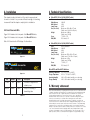
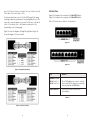
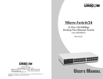
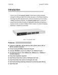
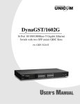
MicroGST-5
MicroGST-8
5 or 8 Port 10/100/1000Base-T
Desktop Switch
MicroGST-5
MicroGST-8
908 Canada Court
City of Industry, CA 91748 U.S.A.
Phone: 626.964.7873 or 800.346.6668 Fax: 626.964.7880
www.unicomlink.com
e-mail: [email protected]
©UNICOM 2009. UNICOM and “A Network Systems Solution” are trademarks of UNICOM Electric, Inc.
All rights reserved. Specifications subject to change without notice.
Rev: 10.09
GEP-32005T-1
GEP-32008T-1
USER’S MANUAL
The information in this guide may be changed without notice. The manufacturer assumes no
responsibility for any errors which may appear in this guide.
1. Introduction
Copyright 2009. All right are reserved. No Part of the contents of this guide maybe transmitted or
reproduced in any form or by any means without the written permission of us. Printed in Taiwan.
Thank you for purchasing Unicom’s MicroGST-5 or MicroGST-8 Desktop
Gigabit Switch. Before you start installing the switch, verify the following
parts in the package.
Ethernet is a trademark of XEROX Corporation. Microsoft, Windows and Windows logo are trademarks
of Microsoft Corporation.
User’s Guide: Version 1.04
FCC Statement
This product has been tested and found to comply with the limits for a Class A digital device pursuant
to Part 15 of FCC Rules. These limits are designed to provide reasonable protection against such
interference when operating in a commercial environment. This equipment generates uses and can
radiate radio frequency energy, and if not installed and used according to the instructions, may cause
harmful interference to radio communications.
Operation of this equipment in a residential area is likely to cause interference, in which case the user,
at his or her own expense will be required to take whatever measures to correct the interference.
CE Mark Warning
This is a Class A product. In a domestic environment, this product may cause radio interference in
which case the user may be required to take adequate measures.
1.1 The package contains
Every switch contains the following:
■
One MicroGST-5 or MicroGST-8 Desktop Gigabit Switch
■
One AC Power Adapter
■
One User’s Guide
IMPORTANT: If any piece is missing or damaged, please contact your
local dealer or reseller for service.
1.2 Features
For Your Records
■
Auto MDI/MDI-X
■
Head-of-line blocking prevention.
■
Flow Control ensures no packet loss, back pressure for half
duplex operation and IEEE 802.3x for full duplex operation
■
Store and Forward switching methodology to ensure low latency
and high data integrity, eliminates unnecessary traffic and
relieves congestion on critical network paths
■
No fan for low noise
Product Name:
Serial Number:
Date of Purchase:
Purchased from:
Notes:
For full coverage of your warranty, be sure
to register your product using the enclosed
registration card.
8
1
2. Installation
4 Technical Specifications
This chapter describes the function of the switch components and
shows how to install it on your network. Basic knowledge of networking
is assumed. Read this chapter completely before installation.
■
MicroGST-5 (5-Port 10/100/1000T switch)
Ports
Buffer Memory
MAC Address
Jumbo Frame
Size (W x D x H)
2.1 Front View and LEDs
Weight
Figure 2.1-1 illustrates the front panel of the MicroGST-5 Switch;
Figure 2.1-2 illustrates the front panel of the MicroGST-8 Switch.
Power
EMI/EMC
5-Port 1000Base-T
104 KB
1000
9 KB
Metal case: 109 x 84 x 27 (mm)
Plastic case: 120 x 84 x 32 (mm)
Metal case: 0.48 kg
Plastic case: 0.49 kg
7.5 VDC, 0.7 A
FCC Class A, CE
Table 2.1-1 describes the LED display of both switches.
■
Figure 2.1-1
MicroGST-8 (8-Port 10/100/1000T switch)
Ports
Buffer Memory
MAC Address
Jumbo Frame
Size (W x D x H)
Weight
Power
EMI/EMC
8-Port 1000Base-T
192 KB
4000
9 KB
Metal case: 158 x 104 x 27 (mm)
Plastic case: 170 x 106 x 32 (mm)
Metal case: 0.63 g
Plastic case: 0.49 kg
7.5 VDC, 0.7
FCC Class A, CE
MicroGST-5 and MicroGST-8 Switches:
Figure 2.1-2
LED
Status
Color
Description
Power
On
Green
The switch is supplied with
suitable power.
LNK/ACT
Blinks
Green
The port is receiving or
transmitting data.
Table 2.1-1
2
Operating Temperature
Storage Temperature
Operating Humidity
Storage Humidity
0°C to 40°C (32°F to 122°F)
-40°C to 70°C (-40°F to 158°F)
20% to 85% relative humidity, non-condensing
20% to 90% relative humidity, non-condensing
5. Warranty statement
We provide this limited warranty for it originally purchased the product from us or its authorized reseller
or distributor. We guarantee that equipment is free from physical defects in workmanship and material
under normal use from the date of original retail purchase of the Hardware. If the product proves
defective during this warranty period, call our Customer Service in order to obtain a Return
Authorization number. Be sure to have a proof of purchase on hand when calling. Return requests
cannot be processed without proof of purchase. When returning a product, mark the Return
Authorization Number clearly on the package pack and include you original proof of purchase. All
customers outside the R.O.C. shall be held responsible for shipping and handling charges. In no event
shall our liability exceed the price paid for the product from direct, incidental or consequential damage
resulting from the use of the product, its accompanying software, or its documentation. We make no
warranty or representation, expressed, implied, or statutory, with respect to its products or the contents
or use of this documentation and all accompanying software, and specifically disclaim its quality,
performance, merchantability, or fitness for any particular purpose. We reserve the right to revise or
update its products, software, or documentation without obligation to notify any individual or entity.
7
wires of 1,2,3,6 are reversed so that wire 1 become 3 at the other end
of the cable, 2 becomes 6, and so forth.
To determine which wire is wire 1, hold the RJ-45 plug with the spring
clip facing towards the ground and the end pointing away from you. The
copper wires exposed upwards to your view. The first wire on the far left
is wire 1. You can also refer to the illustrations and charts of the
internal wiring on the following page.
2.2 Rear View
Figure 2.1-1 illustrates the rear panel of the MicroGST-5 Switch;
Figure 2.1-2 illustrates the rear panel of the MicroGST-8 Switch.
Table 2.2-1 shows the port function of both switches.
Figure 3-1 shows the diagram of Straight Through Cables. Figure 3-2
shows the diagram of Crossover Cables.
Figure 2.2-1
Figure 2.2-2
Figure 3-1: Straight Through Cabling
Port
1000Base-T Ports
5-Port: Ports 1–5
8-Port: Ports 1–8
Power Connector
Function
These 5/8 Gigabit ports connect to network
devices such as PCs, print servers and other
network peripherals at 1000 Mbps.
This is where you will connect the AC
power adapter.
Table 2.2-1
Figure 3-2: Crossover Cabling
6
3
2.3 Installing the switch
3. Specifications
The MicroGST-5 and 8 Switches do not need software configuration. To
install the switches, simply complete the following steps:
3.1 Cable Specifications
Step 1
■
Select a location for your switch.
Table 3-1 lists the cables you can use and their specifications.
■
Put the switch on a sturdy surface.
■
Keep enough ventilation space between the switch and the
surrounding objects.
Caution:
Please do not use telephone cables. Telephone cables do not support
Ethernet or Fast Ethernet
Note: When choosing a location, keep in mind the
environmental restrictions discussed in Chapter 3,
Specifications.
Step 2
Cable Requirement
Maximum Length
10Base-T
Category 3 or above, UTP or STP
328 ft (100M)
100Base-TX
Category 5 or above, UTP or STP
328 ft (100M)
1000Base-T
Category 5e or above, UTP or STP
328 ft (100M)
Connect the switch to network devices
■
■
Connect one end of a standard network cable to the RJ-45
ports on the back of the switch.
Connect the other end of the cable to the network devices
such as printer servers, workstations or routers.
Note: Connection to the Switch requires UTP Category 5 (or
greater) network cabling with RJ-45 plugs. For more
information, please see the Cabling Specification in Chapter
3, Specifications.
Step 3
Ethernet Type
Supply power to the Switch.
■
Connect one end of the power cable to the switch
■
Connect the power cube end of the power adapter cable to
a standard wall outlet.
When the switch receives power, the POWER LED and the LINK/ACT LED
should remain solid green.
Table 3-1 Straight-Through and Crossover Cable Specifications
Twisted-pair cabling comes in various grades, or categories. Category 5
is required for Fast Ethernet, and is also the most reliable and most
commonly used category. You can buy UTP Category 5 (Unshielded
Twisted Pair) Ethernet cabling in pre-crimped lengths, or you can crimp
your own. Crimping your own can result in faulty connections if the RJ-45
plugs are not attached properly. Pre-crimped Category 5 cabling is
available at most computer retail stores.
The most reliable and commonly used type of Category 5 cabling used
is UTP, or “unshielded twisted pair.” STP, or “shielded twisted pair”
wiring is only necessary for network environments exposed to excessive
amounts of electromagnetic interference, or EMI. These environments
include areas with high sources of electrical power, air conditioning,
generators, and radio signals. STP is also used for wiring outdoors.
There are two types of the wiring: Straight-Through Cables and Crossover
Cables. Category 5 UTP/STP cable has eight wires inside the sheath.
The wires form four pairs. Straight-Through Cables have identical pinouts
at both ends while Crossover Cables have a different pin arrangement
at each end.
In a straight-through cable, wires 1,2,3,4,5,6,7 and 8 at one end of the
cable are still wires 1~8 at the other end. In a crossover cable, the
4
5